1
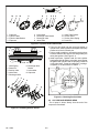
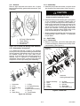
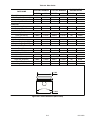
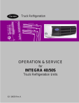
Compressor
R
WORKSHOP MANUAL
for
MODEL 05G TWIN PORT
COMPRESSOR
62--11052 Rev C
WORKSHOP MANUAL
MODEL 05G TWIN PORT
COMPRESSOR
SAFETY SUMMARY
GENERAL SAFETY NOTICES
The following general safety notices supplement the specific warnings and cautions appearing elsewhere in
this manual. They are recommended precautions that must be understood and applied during maintenance of
the equipment covered herein. The general safety notices are presented in the following three sections
labeled: First Aid, Operating Precautions and Maintenance Precautions. A listing of the specific warnings and
cautions appearing elsewhere in the manual follows the general safety notices.
FIRST AID
An injury, no matter how slight, should never go unattended. Always obtain first aid or medical attention
immediately.
OPERATING PRECAUTIONS
Always wear safety glasses.
No work should be performed on the unit until all circuit breakers and start--stop switches are turned off, and
power supply is disconnected.
Always work in pairs. Never work on the equipment alone.
MAINTENANCE PRECAUTIONS
Be sure power is turned off before working on motors, controllers, solenoid valves and electrical control
switches. Tag circuit breaker and power supply to prevent accidental energizing of circuit.
Do not bypass any electrical safety devices, e.g. bridging an overload, or using any sort of jumper wires.
Problems with the system should be diagnosed, and any necessary repairs performed, by qualified service
personnel.
WARNING AND CAUTION STATEMENTS
To help identify the label hazards on the unit and explain the level of awareness each one carries, an
explanation is given with the appropriate consequences:
DANGER
DANGER -- warns against an immediate hazard which WILL result in severe personal injury or
death.
WARNING
WARNING -- warns against hazards or unsafe conditions which COULD result in severe personal injury or death.
CAUTION
CAUTION -- warns against potential hazard or unsafe practice which could result in minor
personal injury, or product or property damage.
NOTE
NOTE -- gives helpful information that may help and avoid equipment and property damage.
Safety - 1
62--11052
SPECIFIC WARNING AND CAUTION STATEMENTS
The statements listed below are specifically applicable to this unit and appear elsewhere in this manual.
These recommended precautions must be understood and applied during operation and maintenance of the
equipment covered herein.
WARNING
Do not operate compressor unless suction and discharge service valves are open.
WARNING
Midseat service valves or by other means relieve pressure in replacement compressor before
removing plugs.
WARNING
Do not unscrew capscrews all the way before breaking seal. Entrapped pressure could result
in injury.
CAUTION
The high capacity oil pump must be set to rotate in the same direction as the crankshaft.
(Refer to Section 3.5)
CAUTION
Ensure that thrust washer does not fall off dowel pins while installing oil pump.
CAUTION
Do not allow crankshaft to drop on connecting rods inside the crankcase when removing the
crankshaft.
CAUTION
Do not allow crankshaft to drop on connecting rods inside the crankcase when installing the
crankshaft.
62--11052
Safety - 2
TABLE OF CONTENTS
PARAGRAPH NUMBER
Page
SAFETY SUMMARY . . . . . . . . . . . . . . . . . . . . . . . . . . . . . . . . . . . . . . . . . . . . . . . . . . . . . . . . . . . . . . . . . . . .
Safety--1
GENERAL SAFETY NOTICES . . . . . . . . . . . . . . . . . . . . . . . . . . . . . . . . . . . . . . . . . . . . . . . . . . . . . . . . . . . . Safety--1
FIRST AID . . . . . . . . . . . . . . . . . . . . . . . . . . . . . . . . . . . . . . . . . . . . . . . . . . . . . . . . . . . . . . . . . . . . . . . . . . . . . Safety--1
OPERATING PRECAUTIONS . . . . . . . . . . . . . . . . . . . . . . . . . . . . . . . . . . . . . . . . . . . . . . . . . . . . . . . . . . . . Safety--1
MAINTENANCE PRECAUTIONS . . . . . . . . . . . . . . . . . . . . . . . . . . . . . . . . . . . . . . . . . . . . . . . . . . . . . . . . . . Safety--1
WARNINGS AND CAUTIONS . . . . . . . . . . . . . . . . . . . . . . . . . . . . . . . . . . . . . . . . . . . . . . . . . . . . . . . . . . . . . Safety--1
SPECIFIC WARNINGS AND CAUTIONS . . . . . . . . . . . . . . . . . . . . . . . . . . . . . . . . . . . . . . . . . . . . . . . . . . . Safety--2
DESCRIPTION . . . . . . . . . . . . . . . . . . . . . . . . . . . . . . . . . . . . . . . . . . . . . . . . . . . . . . . . . . . . . . . . . . . . . . . . . . . . . . .
1--1
1.1
1.2
INTRODUCTION . . . . . . . . . . . . . . . . . . . . . . . . . . . . . . . . . . . . . . . . . . . . . . . . . . . . . . . . . . . . . . . . . . . . .
GENERAL DESCRIPTION . . . . . . . . . . . . . . . . . . . . . . . . . . . . . . . . . . . . . . . . . . . . . . . . . . . . . . . . . . . . .
1--1
1--1
1.3
COMPRESSOR REFERENCE DATA . . . . . . . . . . . . . . . . . . . . . . . . . . . . . . . . . . . . . . . . . . . . . . . . . . . .
1--1
1.4
DETAILED DESCRIPTION . . . . . . . . . . . . . . . . . . . . . . . . . . . . . . . . . . . . . . . . . . . . . . . . . . . . . . . . . . . . .
1.4.1 Service Valves . . . . . . . . . . . . . . . . . . . . . . . . . . . . . . . . . . . . . . . . . . . . . . . . . . . . . . . . . . . . . . . . . . . .
1--3
1--3
1.4.2 Suction And Discharge Valves . . . . . . . . . . . . . . . . . . . . . . . . . . . . . . . . . . . . . . . . . . . . . . . . . . . . . .
1--3
1.4.3 Lubrication System . . . . . . . . . . . . . . . . . . . . . . . . . . . . . . . . . . . . . . . . . . . . . . . . . . . . . . . . . . . . . . . .
1.4.4 Shaft Seal Reservoir . . . . . . . . . . . . . . . . . . . . . . . . . . . . . . . . . . . . . . . . . . . . . . . . . . . . . . . . . . . . . . .
1--3
1--3
COMPRESSOR UNLOADERS . . . . . . . . . . . . . . . . . . . . . . . . . . . . . . . . . . . . . . . . . . . . . . . . . . . . . . . . .
1--4
1.5.1 Electric--Controlled Unloaders . . . . . . . . . . . . . . . . . . . . . . . . . . . . . . . . . . . . . . . . . . . . . . . . . . . . . . .
1.5.2 Pressure--Operated Unloaders . . . . . . . . . . . . . . . . . . . . . . . . . . . . . . . . . . . . . . . . . . . . . . . . . . . . . .
1--4
1--5
1.5
COMPRESSOR REPLACEMENT . . . . . . . . . . . . . . . . . . . . . . . . . . . . . . . . . . . . . . . . . . . . . . . . . . . . . . . . . . . . . . .
2.1
2.2
2--1
COMPRESSOR REMOVAL . . . . . . . . . . . . . . . . . . . . . . . . . . . . . . . . . . . . . . . . . . . . . . . . . . . . . . . . . . . .
COMPRESSOR REPLACEMENT . . . . . . . . . . . . . . . . . . . . . . . . . . . . . . . . . . . . . . . . . . . . . . . . . . . . . .
2--1
2--1
2.2.1 Installing Compressor Unloaders . . . . . . . . . . . . . . . . . . . . . . . . . . . . . . . . . . . . . . . . . . . . . . . . . . . .
2--1
2.2.2 INSTALLING COMPRESSOR . . . . . . . . . . . . . . . . . . . . . . . . . . . . . . . . . . . . . . . . . . . . . . . . . . . . . . . . . .
COMPRESSOR MAINTENANCE . . . . . . . . . . . . . . . . . . . . . . . . . . . . . . . . . . . . . . . . . . . . . . . . . . . . . . . . . . . . . . .
2--2
3--1
3.1
SHAFT SEAL RESERVOIR . . . . . . . . . . . . . . . . . . . . . . . . . . . . . . . . . . . . . . . . . . . . . . . . . . . . . . . . . . . .
3--1
3.2
3.3
INTRODUCTION . . . . . . . . . . . . . . . . . . . . . . . . . . . . . . . . . . . . . . . . . . . . . . . . . . . . . . . . . . . . . . . . . . . . .
INSPECTION AND PREPARATION FOR REASSEMBLY . . . . . . . . . . . . . . . . . . . . . . . . . . . . . . . . . .
3--1
3--1
3.4
CYLINDER HEAD AND VALVE PLATE . . . . . . . . . . . . . . . . . . . . . . . . . . . . . . . . . . . . . . . . . . . . . . . . . .
3--1
3.4.1 Disassembly . . . . . . . . . . . . . . . . . . . . . . . . . . . . . . . . . . . . . . . . . . . . . . . . . . . . . . . . . . . . . . . . . . . . . .
3.4.2 Reassembly . . . . . . . . . . . . . . . . . . . . . . . . . . . . . . . . . . . . . . . . . . . . . . . . . . . . . . . . . . . . . . . . . . . . . .
3--1
3--1
OIL PUMP AND BEARING HEAD . . . . . . . . . . . . . . . . . . . . . . . . . . . . . . . . . . . . . . . . . . . . . . . . . . . . . .
3--2
3.5.1 Removal . . . . . . . . . . . . . . . . . . . . . . . . . . . . . . . . . . . . . . . . . . . . . . . . . . . . . . . . . . . . . . . . . . . . . . . . .
3.5.2 Disassembly, & Inspection . . . . . . . . . . . . . . . . . . . . . . . . . . . . . . . . . . . . . . . . . . . . . . . . . . . . . . . . . .
3--3
3--3
3.5.3 Reassembly . . . . . . . . . . . . . . . . . . . . . . . . . . . . . . . . . . . . . . . . . . . . . . . . . . . . . . . . . . . . . . . . . . . . . .
3--3
SHAFT SEAL . . . . . . . . . . . . . . . . . . . . . . . . . . . . . . . . . . . . . . . . . . . . . . . . . . . . . . . . . . . . . . . . . . . . . . . .
3.6.1 Disassembly . . . . . . . . . . . . . . . . . . . . . . . . . . . . . . . . . . . . . . . . . . . . . . . . . . . . . . . . . . . . . . . . . . . . . .
3--3
3--3
3.6.2 Reassembly . . . . . . . . . . . . . . . . . . . . . . . . . . . . . . . . . . . . . . . . . . . . . . . . . . . . . . . . . . . . . . . . . . . . . .
3.7 COMPRESSOR RUNNING GEAR REMOVAL . . . . . . . . . . . . . . . . . . . . . . . . . . . . . . . . . . . . . . . . . . . .
3--4
3--4
3.7.1 Bottom Plate, Strainer, and Connecting Rod Caps . . . . . . . . . . . . . . . . . . . . . . . . . . . . . . . . . . . . .
3--4
3.7.2 Crankshaft and Seal End Thrust Washer . . . . . . . . . . . . . . . . . . . . . . . . . . . . . . . . . . . . . . . . . . . . .
3.7.3 Pistons, Rods, and Rings . . . . . . . . . . . . . . . . . . . . . . . . . . . . . . . . . . . . . . . . . . . . . . . . . . . . . . . . . . .
3--5
3--5
3.7.4 Seal End Main Bearings . . . . . . . . . . . . . . . . . . . . . . . . . . . . . . . . . . . . . . . . . . . . . . . . . . . . . . . . . . . .
3--6
3.5
3.6
i
62--11052
Page
PARAGRAPH NUMBER
3.8 COMPRESSOR RUNNING GEAR REASSEMBLY . . . . . . . . . . . . . . . . . . . . . . . . . . . . . . . . . . . . . . . .
3--6
3.8.1 Seal End Main Bearings . . . . . . . . . . . . . . . . . . . . . . . . . . . . . . . . . . . . . . . . . . . . . . . . . . . . . . . . . . . .
3--6
3.8.2 Pistons, Rods, and Rings . . . . . . . . . . . . . . . . . . . . . . . . . . . . . . . . . . . . . . . . . . . . . . . . . . . . . . . . . . .
3--6
3.8.3 Crankshaft and Seal End Thrust Washer . . . . . . . . . . . . . . . . . . . . . . . . . . . . . . . . . . . . . . . . . . . . .
3--7
3.8.4 Bottom Plate, Strainer, and Connecting Rod Caps . . . . . . . . . . . . . . . . . . . . . . . . . . . . . . . . . . . . .
3--7
3.9 SUCTION STRAINER . . . . . . . . . . . . . . . . . . . . . . . . . . . . . . . . . . . . . . . . . . . . . . . . . . . . . . . . . . . . . . . . .
3--7
3.10 ADDING OIL . . . . . . . . . . . . . . . . . . . . . . . . . . . . . . . . . . . . . . . . . . . . . . . . . . . . . . . . . . . . . . . . . . . . . . . . .
3--7
3.11 INSTALLING COMPRESSOR . . . . . . . . . . . . . . . . . . . . . . . . . . . . . . . . . . . . . . . . . . . . . . . . . . . . . . . . . .
3--7
LIST OF ILLUSTRATIONS
FIGURE NUMBER
Figure 1--1. Model 05G Compressor . . . . . . . . . . . . . . . . . . . . . . . . . . . . . . . . . . . . . . . . . . . . . . . . . . . . . . . . . . . .
Figure 1--2. Suction & Discharge Valve . . . . . . . . . . . . . . . . . . . . . . . . . . . . . . . . . . . . . . . . . . . . . . . . . . . . . . . . . .
Figure 1--3. Oil Pump . . . . . . . . . . . . . . . . . . . . . . . . . . . . . . . . . . . . . . . . . . . . . . . . . . . . . . . . . . . . . . . . . . . . . . . . .
Figure 1--4. Shaft Seal Reservoir . . . . . . . . . . . . . . . . . . . . . . . . . . . . . . . . . . . . . . . . . . . . . . . . . . . . . . . . . . . . . . .
Figure 1--5. Compressor Unloader . . . . . . . . . . . . . . . . . . . . . . . . . . . . . . . . . . . . . . . . . . . . . . . . . . . . . . . . . . . . .
Figure 1--6. Electric--Operated Unloader--Unloaded Operation . . . . . . . . . . . . . . . . . . . . . . . . . . . . . . . . . . . . . .
Figure 1--7. Electric--Operated Unloader--Loaded Operation . . . . . . . . . . . . . . . . . . . . . . . . . . . . . . . . . . . . . . . .
Figure 1--8. Pressure--Operated Unloader Loaded Operation . . . . . . . . . . . . . . . . . . . . . . . . . . . . . . . . . . . . . . .
Figure 1--9. Pressure--Operated Unloader --Unloaded Operation . . . . . . . . . . . . . . . . . . . . . . . . . . . . . . . . . . . .
Figure 2--1. Removal of Piston Plug . . . . . . . . . . . . . . . . . . . . . . . . . . . . . . . . . . . . . . . . . . . . . . . . . . . . . . . . . . . . .
Figure 2--2. Oil Level in Sight Glass . . . . . . . . . . . . . . . . . . . . . . . . . . . . . . . . . . . . . . . . . . . . . . . . . . . . . . . . . . . . .
Figure 3--1. Shaft Seal Reservoir . . . . . . . . . . . . . . . . . . . . . . . . . . . . . . . . . . . . . . . . . . . . . . . . . . . . . . . . . . . . . . .
Figure 3--2. Cylinder Head & Valve Plate . . . . . . . . . . . . . . . . . . . . . . . . . . . . . . . . . . . . . . . . . . . . . . . . . . . . . . . .
Figure 3--3. Installing Suction Valves . . . . . . . . . . . . . . . . . . . . . . . . . . . . . . . . . . . . . . . . . . . . . . . . . . . . . . . . . . . .
Figure 3--4. Checking Suction Valve . . . . . . . . . . . . . . . . . . . . . . . . . . . . . . . . . . . . . . . . . . . . . . . . . . . . . . . . . . . . .
Figure 3--5. Oil Pump and Bearing Head Assembly . . . . . . . . . . . . . . . . . . . . . . . . . . . . . . . . . . . . . . . . . . . . . . .
Figure 3--6. Oil Pump . . . . . . . . . . . . . . . . . . . . . . . . . . . . . . . . . . . . . . . . . . . . . . . . . . . . . . . . . . . . . . . . . . . . . . . . .
Figure 3--7. Shaft Seal . . . . . . . . . . . . . . . . . . . . . . . . . . . . . . . . . . . . . . . . . . . . . . . . . . . . . . . . . . . . . . . . . . . . . . . .
Figure 3--8. Shaft Seal Removal . . . . . . . . . . . . . . . . . . . . . . . . . . . . . . . . . . . . . . . . . . . . . . . . . . . . . . . . . . . . . . . .
Figure 3--9. TOP Orientation . . . . . . . . . . . . . . . . . . . . . . . . . . . . . . . . . . . . . . . . . . . . . . . . . . . . . . . . . . . . . . . . . . .
Figure 3--10. Bottom Plate Removal . . . . . . . . . . . . . . . . . . . . . . . . . . . . . . . . . . . . . . . . . . . . . . . . . . . . . . . . . . . .
Figure 3--11. Bottom Plate and Oil Strainer Removed . . . . . . . . . . . . . . . . . . . . . . . . . . . . . . . . . . . . . . . . . . . . . .
Figure 3--12. Piston Rings Removed . . . . . . . . . . . . . . . . . . . . . . . . . . . . . . . . . . . . . . . . . . . . . . . . . . . . . . . . . . . .
Figure 3--13. Connecting Rod, Piston, and Pin . . . . . . . . . . . . . . . . . . . . . . . . . . . . . . . . . . . . . . . . . . . . . . . . . . . .
Figure 3--14. Seal End Main Bearings . . . . . . . . . . . . . . . . . . . . . . . . . . . . . . . . . . . . . . . . . . . . . . . . . . . . . . . . . . .
Figure 3--15. Piston . . . . . . . . . . . . . . . . . . . . . . . . . . . . . . . . . . . . . . . . . . . . . . . . . . . . . . . . . . . . . . . . . . . . . . . . . . .
Figure 3--16. Correct Piston in CylinderOrientation . . . . . . . . . . . . . . . . . . . . . . . . . . . . . . . . . . . . . . . . . . . . . . . .
Figure 3--17. Installing Piston Rod Assemblies and Seal End Thrust Washer . . . . . . . . . . . . . . . . . . . . . . . . .
Figure 3--18. Piston Rings . . . . . . . . . . . . . . . . . . . . . . . . . . . . . . . . . . . . . . . . . . . . . . . . . . . . . . . . . . . . . . . . . . . . .
Figure 3--19. Installing Pistons . . . . . . . . . . . . . . . . . . . . . . . . . . . . . . . . . . . . . . . . . . . . . . . . . . . . . . . . . . . . . . . . .
Figure 3--20. Installing Suction Strainer . . . . . . . . . . . . . . . . . . . . . . . . . . . . . . . . . . . . . . . . . . . . . . . . . . . . . . . . . .
Figure 3--21. Piston Dimension (Wear Limits) . . . . . . . . . . . . . . . . . . . . . . . . . . . . . . . . . . . . . . . . . . . . . . . . . . . .
Page
1--2
1--3
1--3
1--3
1--4
1--4
1--5
1--5
1--5
2--1
2--2
3--1
3--2
3--2
3--2
3--3
3--3
3--3
3--4
3--4
3--5
3--5
3--5
3--5
3--6
3--6
3--6
3--6
3--7
3--7
3--7
3--9
LIST OF TABLES
TABLE NUMBER
Page
Table 1--1. Compressor Reference Data . . . . . . . . . . . . . . . . . . . . . . . . . . . . . . . . . . . . . . . . . . . . . . . . . . . . . . . . . .
1--1
Table 1--2. Oils . . . . . . . . . . . . . . . . . . . . . . . . . . . . . . . . . . . . . . . . . . . . . . . . . . . . . . . . . . . . . . . . . . . . . . . . . . . . . . . .
1--1
Table 3--1. Torque Values . . . . . . . . . . . . . . . . . . . . . . . . . . . . . . . . . . . . . . . . . . . . . . . . . . . . . . . . . . . . . . . . . . . . . . .
3--8
Table 3--2. Wear Limits . . . . . . . . . . . . . . . . . . . . . . . . . . . . . . . . . . . . . . . . . . . . . . . . . . . . . . . . . . . . . . . . . . . . . . . . .
3--9
62--11052
ii
SECTION 1
DESCRIPTION
1.1 INTRODUCTION
1.3 COMPRESSOR REFERENCE DATA
This workshop manual covers the Carrier Transicold
Model 05G Twin Port compressors. These
compressors are designed for refrigeration (trailer) or
air conditioning (bus & rail) applications. (See
Figure 1-1) A detailed list of tools needed to service the
05G Twin Port compressor may be found in the Service
Tool catalog 62--03213--. Replacement parts may be
found in the Service Parts List for Model 05G Twin Port
Compressor 62--11053--.
Table 1-1. Compressor Reference Data
Model
Displacement
No. Cylinders
Bore
05G--37CFM
37CFM
05G--41CFM
41CFM
6
50.8 mm (2.00 in)
49.2 mm
54.36 mm
Stroke
(1.937 in)
(2.14 in)
Weight
62 kg (137 lbs)
SPEED (RPM) FOR OIL PUMP
Low Profile
500 to 2200
1.2 GENERAL DESCRIPTION
The 05G Twin Port compressors are of the open--drive
reciprocating type. A crankshaft, connecting rods,
pistons, and reed type valves accomplish vapor
compression. Compressor wear is minimized by splash
lubrication and by force feed lubrication. The oil pump is
driven directly from the end of the compressor
crankshaft. (See Figure 1-3)
The end of the crankshaft, which extends outside the
crankcase, is adaptable to a variety of direct drive or
belt--driven clutch mechanisms. A mechanical seal
prevents refrigerant leakage where the rotating shaft
passes through the crankcase. A shaft seal reservoir is
provided to collect any oil seepage that might escape
the seal.
The compressor is equipped with flanges for connecting
suction and discharge service valves. Connections are
also provided for pressure gauges and safety cutout
switches. Sight glasses installed on both sides of the
crankcase, provides a means for checking oil level in the
compressor crankcase. A drain plug facilitates draining
of oil from the crankcase and an oil fill plug enables
addition of oil when necessary. A bottom plate provides
access through the bottom of the crankcase for
maintenance.
NOTE
The oils below are suitable for use with
evaporator temperatures above --40°F (--40°C).
Table 1-2. Oils
Approved Oil for REFRIGERATION USE
(TRAILER)
Refrigerant
Oil
R--12, R--22, R--500
Alkyl Benzene (Synthetic)
or R--502
P/N 07--00274--00
Polyolester (POE)
R--404A
P/N 07--00317--00PK6
Approved Oil for AIR CONDITIONING USE
(BUS AND RAIL)
Refrigerant
Oil
R--12, R--22,
Mineral (150 Viscosity)
R--500 or R--502
P/N 07--00275--00
R--12, R--22,
Mineral (300 Viscosity)
R--502
P/N 07--00377--00
WARNING
Do not operate compressor unless suction
and discharge service valves are open.
Alkyl Benzene (Synthetic)
R--22
P/N 07--00430--00
Capacity of the Model 05G Twin Port compressor is
determined by piston displacement and clearance,
Polyolester (POE)
R--134a
suction and discharge valve size, compressor speed,
P/N 07--00317--00PK6
suction and discharge pressure, type of refrigerant, and
unloader valves.
NOTE
Proper use and storage of Polyester (POE) type oil used with HFC refrigerants is critical. This type of oil is
extremely hygroscopic, meaning that if allowed to become exposed to the atmosphere, it can collect moisture
that leads to the formation of acids that will damage refrigeration components. Some refrigeration assemblies
such as o--ring assemblies, compressor shaft seals and most solenoid valves require that refrigerant oil be
applied to some of the parts during the assembly process. When this is needed, always use alkylated
benzene oil CTD P/N 07--00274 (Zerol 150) even for R134a or R404A systems. All refrigerant oils must be
stored in a sealed, airtight container.
1--1
62--11052
2
1
3
4
5
5
11
10
COMPRESSOR WITH
MOUNTING FLANGE
(ULTRA TYPE SHOWN)
9
12
8
7
6
1
2
3
4
5
11
5
10
COMPRESSOR WITHOUT
MOUNTING FLANGE
9
12
8
1.
2.
3.
4.
5.
6.
7
6
7.
8.
9.
10.
11.
12.
Discharge Service Valve
High Pressure Connection
Low Pressure Connection
Suction Service Valve
Guage Connection
Oil Fill Plug
Oil Level Sight Glass
Bottom Plate
Oil Drain Plug
Oil Pump (See Figure 1-3)
Unloader
Shaft Seal Reservoir
Figure 1-1. Model 05G Compressor
62--11052
1--2
1.4 DETAILED DESCRIPTION
1.4.1 Service Valves
The suction and discharge service valves used on the
compressor are equipped with mating flanges for
connection to flanges on the compressor. These valves
are provided with a double seat and a gauge connection,
which allows servicing of the compressor and
refrigerant lines (See Figure 1-1).
Turning the valve stem counterclockwise (all the way
out) will backseat the valve to open the suction or
discharge line to the compressor and close off the
gauge connection. In normal operation, the valve is
backseated to allow full flow through the valve. The
valve should always be backseated when connecting
the service manifold gauge lines to the gauge ports.
Figure 1-3. Oil Pump
The oil flows to the pump end main bearings, connecting
rod bearings and seal end main bearings, where the oil
path is divided into two directions. The largest quantity
flows to the oil relief valve, which regulates oil pressure
at 15 to 18 psi (1.02 to 1.22 bar) above suction pressure.
When the oil pressure reaches 15 to 18 psi (1.02 to 1.22
bar) above suction pressure, the relief valve spring is
moved forward allowing oil to return to the crankcase.
The remaining oil flows through an orifice and into the
shaft seal cavity to provide shaft seal lubrication and
cooling. This oil is then returned to the crankcase
through an overflow passage.
An additional oil pressure relief valve, built into the oil
pump. It opens at speeds above 400 rpm to relieve a
portion of the oil pressure to the crankcase in order to
maintain oil pressure below an acceptable maximum. At
low speeds, the valve is closed to ensure adequate oil
pressure at 400 rpm. At speeds above 1900 rpm, the oil
pressure will be 25 to 30 psi (1.70 to 2.04 bar) above
suction pressure.
The crankcase pressure equalization system consists of
two oil return check valves and a 1/8--inch pressure
equalization port between the suction manifold and
crankcase. Under normal conditions, check valves are
open and allow for oil return to the crankcase. Under
flooded start conditions, pressure rises in the crankcase
and closes the check valves, preventing excess oil loss.
The equalization port allows for release of excessive
pressure, that has built up in the crankcase, to the suction
manifold; this ensures that the oil loss is kept to a
minimum.
1.4.4 Shaft Seal Reservoir
Turning the valve stem clockwise (all the way forward)
will frontseat the valve to close off the suction or
discharge line to isolate the compressor and open the
gauge connection.
To measure suction or discharge pressure, midseat the
valve by opening the valve clockwise about 2 turns. With
the valve stem midway between frontseated and
backseated positions, the suction or discharge line is
open to both the compressor and the gauge connection.
1.4.2 Suction And Discharge Valves
The compressor uses reed type suction and discharge
valves made of highest quality steel for long life. The
valves operate against hardened integral seats in the
valve plate.
The downstroke of the piston admits refrigerant gas
through the suction valve, and then compresses this
gas on the upstroke, thereby raising it’s temperature
and pressure. The compressed gas is prevented from
re--entering the cylinder on it’s next downstroke by the
compressor discharge valve. (See Figure 1-2)
1
2
3
4
5
2
1. Valve Spring
2. Suction Valve
3. Valve Plate
4. Discharge Valve
5. Discharge Valve
Backer
Figure 1-2. Suction & Discharge Valve
1.4.3 Lubrication System
Force--feed lubrication of the compressor is accomplished
by an oil pump (See Figure 1-3) driven directly from the
compressor crankshaft. Refrigeration oil is drawn from the
compressor crankcase through the oil filter screen and
pick up tube to the oil pump located in the bearing head
assembly. The crankshaft is drilled to enable the pump to
supply oil to the main bearings, connecting rod bearings,
and the shaft seal.
1
1. Shaft Seal Reservoir
2. Access Valve (Coreless)
Figure 1-4. Shaft Seal Reservoir
The shaft seal oil reservoir has been fitted to the
crankcase. The coreless access valve taps into the
crankshaft seal cavity where any oil that escapes the
crankshaft seal will form. The coreless access valve
then drains that compressor oil that escapes the
crankshaft seal into the shaft seal reservoir.
1--3
62--11052
When the pressure behind the piston has been reduced
sufficiently, the valve spring will force the piston bypass
valve back, opening the gas bypass from the discharge
manifold to the suction manifold.
Discharge pressure in the discharge manifold will close
the discharge piston check valve assembly (14)
isolating the compressor discharge manifold from the
individual cylinder bank manifold.
The unloaded cylinder bank will continue to operate fully
unloaded until the solenoid valve control device is
de--energized and the gas bypass port is closed.
1.5 COMPRESSOR UNLOADERS
The compressor is equipped with unloaders for capacity
control. This consists of a self--contained, cylinder head
hot gas bypass arrangement. (See Figure 1-5)
The compressor unloader system can be controlled with
either a pressure actuated valve or an electrically
actuated (solenoid) valve.
1.5.1 Electric--Controlled Unloaders
The capacity controlled cylinder is easily identified by an
electric solenoid which extends from the side of the
cylinder head. When the solenoid energizes, the
cylinder unloads allowing discharge gas to circulate as
shown in Figure 1-6. The unloaded cylinder operates
with little or no pressure differential, consuming very
little power. A de--energized solenoid reloads the
cylinder as shown in Figure 1-7.
2
1
3
4
2
3
7
11
10
8
9
5
4
5
6
12
13
14
1
15
6
1. Discharge Check
Valve
2. Discharge Manifold
3. Solenoid Valve
1. Solenoid Valve
2. Valve Stem
3. Gas Bypass Port
4. Spring Guide
5. Spring
6. Piston
7. Piston Bypass Valve
8. Bleed Orifice
9. Strainer
10. Suction Cavity
4. Piston Bypass
Control Valve
5. Cylinder Head
6. Suction Manifold
Figure 1-5. Compressor Unloader
a. Major Working Parts
1. Solenoid and valve system
2. Spring loaded piston type bypass control valve
3. Spring loaded discharge check valve
Figure 1-6. Electric--Operated Unloader-Unloaded Operation
c. Loaded Operation
Discharge pressure bleeds from the discharge manifold
(Figure 1-7, item 15) through the strainer (9) and bleed
orifice (8) to the solenoid valve stem (2) chamber and
the back of the piston bypass valve (7).
b. Unloaded Operation
Pressure from the discharge manifold (Figure 1-6, item
15) passes through the strainer (9) and bleed orifice (8)
to the back of the piston bypass valve (7). Unless bled
away, this pressure would tend to close the piston (6)
against the piston spring (5) pressure.
With the solenoid valve (1) energized the solenoid valve
stem (2) will open the gas bypass port (3).
Refrigerant pressure will be bled to the suction manifold
(10) through the opened gas bypass port . A reduction in
pressure on the piston bypass valve will take place
because the rate of bleed through the gas bypass port is
greater than the rate of bleed through the bleed orifice
(8).
62--11052
11. Cylinder Discharge
Valve
12. Valve Plate
13. Cylinder Suction
Valve
14. Discharge Piston
Check Valve
Assembly
15. Discharge Manifold
With the solenoid valve (1) de--energized the solenoid
valve stem (2) will close the gas bypass port (3).
Refrigerant pressure will overcome the bypass valve
spring (5) tension and force the piston (6) forward
closing the gas bypass from the discharge manifold to
the suction manifold (10).
Cylinder discharge pressure will force open the
discharge piston check valve assembly (14).
Refrigerant gas will pass into the compressor discharge
manifold.
1--4
The loaded cylinder bank will continue to operate fully
loaded until the solenoid valve control device is
energized and the gas bypass port is opened.
2
3
4
5
6
1
2
11
7
10
1
4
3
8
12
9
13
6
14
15
1. Solenoid Valve
2 Valve Stem
3. Gas Bypass Port
4. Spring Guide
5. Spring
6. Piston
7. Piston Bypass Valve
8. Bleed Orifice
9. Strainer
10. Suction Cavity
5
1.
2.
3.
4.
5.
6.
11. Cylinder Discharge
Valve
12. Valve Plate
13. Cylinder Suction
Valve
14. Discharge Piston
Check Valve
Assembly
15. Discharge Manifold
Sealing Cap
Pressure Differential Adjustment Screw
Control Set Point Adjustment Nut
Poppet Valve
Piston Bypass Valve
Discharge Piston Check Valve
Figure 1-8. Pressure--Operated Unloader
Loaded Operation
5
1
2
Figure 1-7. Electric--Operated Unloader-Loaded Operation
1.5.2 Pressure--Operated Unloaders
The pressure--operated unloaders are controlled by
suction pressure and actuated by discharge pressure.
The unloader valve controls two cylinders. On startup,
controlled cylinders do not load up until differential
between suction and discharge pressure is 10 psi (0.68
bar).
During loaded operation, (Figure 1-8) when suction
pressure is above the valve control point, the poppet
valve (4) will close. Discharge gas bleeds into the valve
chamber; the pressure closes the piston bypass valve
(5) and the cylinder bank loads up. Discharge gas
pressure forces the discharge piston check valve (6)
open, permitting gas to enter the discharge manifold.
During unloaded operation, (Figure 1-9) when suction
pressure drops below the valve control point, the poppet
valve (4) will open. Discharge gas bleeds from behind
the bypass piston to the suction manifold. The bypass
piston valve (5) opens, discharge gas is recirculated
back to the suction manifold and the cylinder bank is
unloaded. Reduction in discharge pressure causes the
discharge piston check valve (6) to close, isolating the
cylinder bank from the discharge manifold.
4
3
6
1.
2.
3.
4.
5.
6.
Sealing Cap
Pressure Differential Adjustment Screw
Control Set Point Adjustment Nut
Poppet Valve
Piston Bypass Valve
Discharge Piston Check Valve
Figure 1-9. Pressure--Operated Unloader -Unloaded Operation
1--5
62--11052
SECTION 2
COMPRESSOR REPLACEMENT
2.1 COMPRESSOR REMOVAL
2.2.1 Installing Compressor Unloaders
a. Remove the three socket head capscrews holding
piston plug to cylinder head of the replacement
compressor. See Figure 2-1.
Refer to the operation and service manual covering the
equipment in which the compressor is installed for
specific removal instructions. A general removal
procedure is given below.
1
a. If compressor is completely inoperative, frontseat the
suction and discharge service valves to trap the
refrigerant in the unit. If the compressor will operate,
pump down the unit; then, frontseat the suction and
discharge service valves.
3
b. Ensure power source is removed from any controls
installed on the compressor.
4
2
c. Remove refrigerant from the compressor using a
refrigerant recovery system.
7
5
6
d. Disconnect refrigerant lines at service valve flange
connections on the compressor; retain hardware.
e. Remove any components necessary to gain access
to the compressor or to enable removal.
f. Disconnect the drive mechanism at the compressor.
g. Remove mounting
compressor from unit.
hardware
and
remove
1. Capscrews
2. Flange Cover
3. Gasket
4. Spring
h. If compressor is to be repaired, refer to section 3 for
repair procedures. if a replacement compressor is to
be installed, refer to section 2.2 for replacement
procedures.
5. Bypass Piston Plug
6. Seat Ring
7. Strainer
Figure 2-1. Removal of Piston Plug
b. Remove flange cover, gasket, spring, bypass piston
plug, and seat ring. A tapped hole is provided in piston
plug for use with a jackscrew to enable removal of the
plug. One of the socket head capscrews may be used
as a jackscrew.
c. Remove the three socket head capscrews holding
unloader in the cylinder head of the defective
compressor; remove the unloader and retain the
capscrews.
NOTE
Capscrews removed from the bypass piston
plug flange cover are not interchangeable with
capacity control unloader valve capscrews.
When installing the unloaders, be sure to use
the unloader capscrews.
2.2 COMPRESSOR REPLACEMENT
Consult the unit service parts list for the correct
replacement.
Service replacement compressors are furnished
without suction and discharge service valves and
unloader valves. The service valves are normally
retained on the unit to isolate the refrigerant lines during
compressor replacement. Blank--off pads are installed
on the service replacement compressor valve flanges.
These pads must be removed prior to installing the
compressor. If the defective compressor is to be
returned for overhaul or repair, install the pads on the
compressor for sealing purposes during shipment.
Service replacement compressors are furnished with
cylinder head bypass piston plugs installed on the
unloader flanges in lieu of the unloader valves. The
unloaders (if used) must be removed from the defective
compressor and transferred to the replacement
compressor prior to installation. Refer to section 2.2.1.
d. Using a new gasket and unloader ring pliers (P/N
07--00223), install the unloaders in the cylinder heads
of the replacement compressor. Refer to Table 3-1,
for required torque values.
e. If the defective compressor is to be returned for
overhaul or repair, install the bypass piston plug,
spring, seat ring and flange cover onto the cylinder
heads.
If the defective compressor is to be returned for
overhaul or repair, install the plugs on the compressor
for sealing purposes during shipment.
2--1
62--11052
g. Recheck compressor oil level.
2.2.2 INSTALLING COMPRESSOR
h. Check operation of compressor unloaders (if
installed).
WARNING
Midseat service valves or by other means
relieve
pressure
in
replacement
compressor before removing plugs.
CAUTION
The high capacity oil pump must be set to
rotate in the same direction as the
crankshaft. (Refer to Section 3.5)
a. Install the compressor by reversing the procedure of
section 2.1. Install new locknuts on compressor
mounting bolts and new gaskets on suction and
discharge service valves.
b. Check oil level in sight glass (See Figure 2-2). If
necessary, add or remove oil.
c. Leak test, evacuate, and dehydrate the compressor.
d. Fully backseat suction and discharge service valves.
e. Run the compressor and check for leaks and
noncondensibles in the refrigerant system.
f. Check refrigerant level.
62--11052
PROPER LEVEL IN SIGHT GLASS
Figure 2-2. Oil Level in Sight Glass
2--2
SECTION 3
COMPRESSOR MAINTENANCE
c. Inspect suction and discharge valve seats (on valve
plate).
d. If unloaders are installed, inspect operation of
unloader.
e. After cleaning, ensure all moving parts are coated
with compressor oil before reassembly.
f. Use only new gaskets during reassembly. Ensure all
gaskets (includes cylinder head, valve plate, and unloader or bypass plug gaskets) are installed dry.
3.1 SHAFT SEAL RESERVOIR
The shaft seal reservoir will accumulate up to 3.5
ounces of oil. It should be serviced (checked and
drained) at least once a year. To service the reservoir:
a. Remove the capscrew and washer that secures the
reservoir to the crankcase.
b. Remove the reservoir and properly dispense of the
contents.
1
2
3.4 CYLINDER HEAD AND VALVE PLATE
1 Access Valve
2 Reservoir
3 Capscrew and
Washer
3.4.1 Disassembly
WARNING
3
Do not unscrew capscrews all the way
before breaking seal. Entrapped pressure
could result in injury.
Figure 3-1. Shaft Seal Reservoir
NOTE
a. Loosen cylinder head capscrews. If the head is stuck,
tap it lightly with a wooden or lead mallet to free it. Be
careful not to drop the head or damage the gasket
sealing surface. Remove cylinder head capscrews
and gasket. (See Figure 3-2)
b. Remove the discharge valve capscrews, lock washers, stops, and valves.
c. Free the valve plates from the cylinder deck by using
the discharge valve capscrews, without washers, as
jackscrews through the outermost tapped holes in the
valve plate after the valve stops and valves have
been removed. Remove the valve plate gasket.
d. Discard valves and gaskets. Use only new valves and
gaskets when assembling cylinder head and valve
plate assemblies.
3.4.2 Reassembly
Install only new valves and gaskets, do not interchange
valves.
a. Install the discharge valves and discharge valve
stops with capscrews and lock washers onto the
valve plates. Torque the capscrews to a value shown
in Table 3-1.
b. Turn the valve plate over.
c. Place suction valve on dowel pins.
d. Install the suction valve spring on the dowel pins with
the spring ends bearing away from the cylinder head.
(See Figure 3-3)
Do not return this oil to the compresser. This oil
is contaminated.
Dispose this oil in an
environmentally correct manner.
c. Return the reservoir to its mounting location insuring
that the neck of the reservoir is seated over the access valve.
d. Reinstall the capscrew and washer.
Refer to Table 3-1 for torque values for tightening the
capscrew.
3.2 INTRODUCTION
Prior to disassembly of the compressor, oil must first be
drained from the crankcase. Place the compressor in a
position where it will be convenient to drain the oil.
Remove the oil fill plug to vent the crankcase. Loosen
the drain plug and allow the oil to drain out slowly.
If dismantled parts are to be left overnight or longer, dip
them in clean compressor oil (to prevent rusting) and
store in protected area.
Refer to Table 3-1 for torque values for tightening bolts.
3.3 INSPECTION AND PREPARATION FOR
REASSEMBLY
a. Clean all parts with an approved solvent. Use a stiff
bristle brush to remove dirt from grooves and crevices.
b. Inspect all parts for wear and overall condition.
Replace any defective or excessively worn parts.
3--1
62--11052
4,5
7
6
8
12
1
2
3
4
11
10
9
8
5
6
7
8
Capscrew
Cylinder Head
Cylinder Head Gasket
Capscrew
7
6 5 4
3
9
10
11
12
Lockwasher
Discharge Valve Backer
Discharge Valve
Valve Plate
2
1
Valve Plate Gasket
Suction Valve
Suction Valve Spring
Dowel Pin
Figure 3-2. Cylinder Head & Valve Plate
8
7
e. Place the valve plate and new valve plate gasket on
cylinder deck, ensuring that the valve plate is properly
positioned on the four dowel pins.
f. Using a small screwdriver, operate the suction valves
to ensure that the valve tips are not being held by the
valve plate gasket. (See Figure 3-4)
g. Install capscrews, cylinder head and new cylinder
head gasket with flat side to valve plate, ensuring that
the gasket and cylinder head are properly positioned
on the valve plate. Torque the capscrews, in a diagonal pattern, to a value shown in Table 3-1.
6
5
3
1
1.
2.
3.
4.
5.
4
2
Valve Spring
Dowel Pin
Suction Valve
Valve Plate
Discharge Valve
1
3
6. Discharge Valve
Backer
7. Lockwasher
8. Capscrew
2
4
5
6
Figure 3-4. Checking Suction Valve
3.5 OIL PUMP AND BEARING HEAD
7
The oil pump is driven directly from the end of the
compressor crankshaft.
8
Figure 3-3. Installing Suction Valves
62--11052
3--2
3.5.1 Removal
Remove eight capscrews and remove the oil pump
bearing head assembly, gasket and thrust washer. (See
Figure 3-5.)
3.5.3 Reassembly
a. Install the pump end thrust washer on the two dowel
pins located on the bearing head. (See Figure 3-5.)
CAUTION
1
Ensure that thrust washer does not fall off
dowel pins while installing oil pump.
2
4
1.
2.
3.
4.
b. Install the bearing head assembly with a new gasket
on the compressor crankshaft. Carefully push oil
pump on by hand ensuring that the thrust washer remains on the dowel pins, the tang on the end of the
drive engages the slot in the crankshaft, and the oil
inlet port on the pump is aligned with the oil pickup
tube in the crankcase. The oil pump should mount
flush with the crankcase with the “TOP” stamp on the
pump oriented straight up. (See Figure 3-12)
c. Align the gasket and install the eight capscrews in the
mounting flange. Refer to Table 3-1, for applicable
torque values.
3
3.6 SHAFT SEAL
Oil Pump & Bearing Head
Thrust Washer
Oil Pickup Tube
Oil Inlet Port
3.6.1 Disassembly
a. Remove 6 capscrews, remove the shaft gland plate
or clutch mounting hub. Remove rotor from top of bellows assembly. (See Figure 3-7)
Figure 3-5. Oil Pump and Bearing Head Assembly
3.5.2 Disassembly, & Inspection
If it is determined that the oil pump is not operating
properly, the entire oil pump and bearing head assembly
must be replaced. Replacement parts for the pump are
not available except for the cover plate O--ring.
However, in the event the pump requires inspection or
cleaning, refer to Figure 3-6 for disassembly and
reassembly. Clean all parts; coat all moving parts with
compressor oil before proceeding with reassembly.
11
Standard
Shaft Seal
3
1
5
4
9
6
10
2
10
8
12
7
6
1
2
3
4
5
10
4
5
6
3
9
1
8
2
Used with
Housing Mounted Clutch
7
1
2
3
4
5
6
Capscrews
Cover
Eccentric Ring
Rotor
Idler
Shaft (Drive)
1
2
3
4
5
7 O--Ring
8 Oil Pump & Bearing
9 Dowel Pin
10 Relief Valve Assembly
11 Pins (2)
12 Thrust Washer
Bellows Assembly
Rotor
Gasket
Stator
O--Ring
6
7
8
9
10
Lip Seal
Clutch Mounting Hub
Hub Nut
Gland Plate
Hex Head Screw
Figure 3-7. Shaft Seal
Figure 3-6. Oil Pump
3--3
62--11052
b. Lubricate the end of the crankshaft with clean oil.
c. Using two long screwdrivers, pry out the shaft seal but
do not damage the gasket surface or the crankshaft.
(See Figure 3-8)
NOTE
Do not touch the sealing surfaces with your
fingers.
If the sealing surfaces become
contaminated, clean with isopropyl alcohol and
a clean dry lint--free cloth.
i. Install the stator into the cover/clutch mounting hub.
Insure that the back side of the stator seats to the lip
seal.
NOTE
The shaft seal cover or clutch mounting hub on
this compressor must be oriented so that the oil
communication hole in the cover/hub lines up
correctly with the port in the crankcase. The
cover/hub should mount flush with the
crankcase with the “TOP” stamp on the pump
oriented straight up.
j. Assemble the seal cover/clutch mounting hub, the
gasket and the six hex head screws on to the compressor, paying attention to the orientation of the cover/hub (see Figure 3-9).
Figure 3-8. Shaft Seal Removal
3.6.2 Reassembly
“TOP”
NOTE
Install a new shaft seal assembly and cover
gasket, with the shaft seal cover/clutch
mounting hub. Never install a used seal
assembly or gasket. A new rotor should never
be installed with a used stator. When installing
the seal assembly, use care not to damage the
rotor or stator.
1
1 Seal Cover
2 Mounting Hub
a. Remove the NEW rotor (carbon ring) from the new
seal assembly. Lubricate the shaft and the neoprene
seal bellows where it contacts the shaft with clean/
fresh compressor oil.
b. Insert the NEW seal into the 05G Shaft Seal Tool (P/N
07--00460--00).
c. Slide the seal assembly/ 05G Shaft Seal Tool onto
shaft until the tool bottoms out on the crankshaft.
d. Install the NEW rotor. Ensure that notches in rotor are
aligned with two small knurls inside the seal seat.
Install the new cover plate and gasket.
e. Remove the old stator and O--ring from the shaft seal
cover/clutch mounting hub.
Figure 3-9. TOP Orientation
k. Align the gasket and install the six capscrews in the
mounting flange. Refer to Table 3-1, for applicable
torque values.
3.7 COMPRESSOR RUNNING GEAR REMOVAL
In order to disassemble Piston, Rod and Rings, first the
cylinder heads and valve plate aseemblies, oil pump
and bearing head assemblies and shaft seal must be
removed. (Refer to sections 3.4, 3.5 and 3.6 ).
3.7.1 Bottom Plate, Strainer, and Connecting Rod
Caps
a. Turn the compressor over, bottom side up, and remove the bottom plate. (See Figure 3-10) Scrape off
gasket.
f. Inspect the lip seal that is still in the cover/clutch
mounting hub. If it shows any signs of damage or
wear replace it.
g. Install the lip seal into the cover/clutch mounting hub.
Insure that the back side of the lipseal seats on the
shoulder machined in the cover/clutch mounting hub.
b. Remove the oil strainer.
h. Using clean refrigerant oil, lubricate the new O--ring
and install it into the outside groove of the new stator
being careful not to touch the sealing surfaces of the
stator with your fingers.
62--11052
2
3--4
be installed during compressor reassembly. (See
Figure 3-11)
d. Push the piston rods down so that the piston rings extend below the cylinders. Remove and discard piston
rings. Use only new rings when reassembling the
compressor. (See Figure 3-12.)
3.7.2 Crankshaft and Seal End Thrust Washer
1
2
1 Bottom Plate
2 Oil Strainer
3 Reservoir
3
CAUTION
Do not allow crankshaft to drop on connecting rods inside the crankcase when removing the crankshaft.
Figure 3-10. Bottom Plate Removal
1
a. Push piston rod assemblies out of the way and
remove crankshaft and seal end thrust washer.
b. Remove and check operation of oil return check
valves (See Figure 3-11). The check valves are free
floating devices and can easily be checked visually.
c. Remove and check oil pressure relief valve (See
Figure 3-11). The oil pressure relief valve is a spring
loaded device which can be checked by using a small
piece of stiff wire to ensure that the spring can be
depressed.
d. Remove piston rod assemblies.
3.7.3 Pistons, Rods, and Rings
a. Piston and pin, and connecting rod and rod cap are
matched sets and must not be interchanged. That is,
if either the piston or piston pin is to be replaced, you
must replace both of them. Likewise, if a connecting
rod or rod cap must be replaced, both must be replaced.
b. Match mark and disassemble pistons, pins, connecting rods, and caps. (See Figure 3-13)
2
4
3
1
2
3
4
Oil Pressure Relief Valve
Connecting Rod and Cap
Capscrew
Check Valves
1
2
Figure 3-11. Bottom Plate and Oil Strainer
Removed
3
TOP
6
1
2
3
Figure 3-12. Piston Rings Removed
c. Match mark each connecting rod cap and connecting
rod for correct reassembly. Remove the capscrews,
flat washers and connecting rod caps. It is recommended that the capscrews and flat washers be discarded and new capscrews (special) and flat washers
4
5
Lock Ring
Connecting Rod
Connecting Rod
Cap
4
5
6
Cap Screw
Piston Pin
Piston
Figure 3-13. Connecting Rod, Piston, and Pin
c. Check wear dimensions of disassembled parts to determine if they are worn beyond limits given in
Table 3-2.
3--5
62--11052
d. Measure side clearance between ring and ring
groove in piston. Maximum dimensions are provided
in Table 3-2.
e. If parts are worn beyond limits, replace them in
matched sets as specified above.
f. Coat piston pins with compressor oil and reassemble
pistons, pins, and connecting rods in matched sets.
Figure 3-15. Piston
a. The gap between the ends of the piston rings can be
checked with a feeler gauge by inserting the ring into
the piston bore about one inch below the top of the
bore. Align the ring in the bore by pushing it slightly
with a piston. The maximum and minimum allowable
ring gaps are shown in Table 3-2.
NOTE
Pay particular attention to the orientation of the
piston in relation to the connecting rod, and the
cylinder they are intended for. See Figure 3-15
and .
3.7.4 Seal End Main Bearings
a. Inspect seal end main bearings. Check wear dimensions to determine if they are worn beyond limits given in Table 3-2.
b. If worn beyond limits remove seal end main bearings.
3.8 COMPRESSOR RUNNING GEAR
REASSEMBLY
3.8.1 Seal End Main Bearings
a. When installing new seal end main bearings the oil V
grooves are oriented towards the top of the compressor with oil V grooves pointing to each other. When
installed, there must be a 5/16 inch (7.93 mm) gap
between the two bearings (See Figure 3-14).
b. Line boring seal end main bearings.
Figure 3-16. Correct Piston in Cylinder
Orientation
b. Install the piston and rod assemblies up through the
bottom of the crankcase and into the cylinders. Allow
pistons to extend beyond the top of the cylinder to enable installation of piston rings. Pistons must be
installed so that the chamfer, on the connecting rod,
faces toward the crankshaft journals. Center rods on
each crankshaft throw may be installed in either
direction. (See Figure 3-17)
BOTTOM OF
COMPRESSOR
CHAMFERED EDGE
OIL V GROOVE
5/16
GAP
TOP OF
COMPRESSOR
Figure 3-14. Seal End Main Bearings
3.8.2 Pistons, Rods, and Rings
Prior to installing new piston rings, it is necessary to
break the hard glazed surface of the cylinder in order to
reduce the wearing--in period of the new rings. Break the
glaze by honing lightly in an up and down rotating
motion. Clean thoroughly after breaking glaze.
Some 05G compressors for refrigeration use only may
have contoured pistons (See Figure 3-15). When
installing contoured pistons into compressor, check
suction valve and contoured piston are in the same
orientation.
62--11052
CHAMFERED EDGE
SEAL END
THRUST WASHER
Figure 3-17. Installing Piston Rod Assemblies and
Seal End Thrust Washer
3--6
c. The compressor will be fitted with double ring pistons.
be checked by using a small piece of stiff wire to ensure that the spring mechanism can be depressed.
Compression Ring
Compression Ring
Figure 3-18. Piston Rings
d. The compression ring is chamfered on the inside circumference. This ring is installed with the chamfer towards the top. Stagger the ring end gaps so they are
on opposite sides of the piston.
3.8.3 Crankshaft and Seal End Thrust Washer
a. Two brass thrust washers are used. The pump end
thrust washer is positioned on two dowel pins located
on the bearing head and is installed with the oil pump
and bearing head assembly. The seal end thrust
washer is positioned just ahead of the seal end main
bearing on one dowel pin installed in the crankcase.
Both thrust washers should be inspected for wear and
scoring before reassembly (Refer to Table 3-2).
b. Install the seal end thrust washer on the dowel pin.
(See Figure 3-17) Ensure piston rods are pushed out
of the way and install the crankshaft.
Figure 3-19. Installing Pistons
d. Clean and reinstall the oil strainer.
e. Using a new gasket, install the bottom cover plate.
See figure 1--1 for relative location of compressor
mounting flanges. Torque cover capscrews, in a diagonal pattern, to the torque value shown in Table 3-1.
f. Reassemble the cylinder head, oil pump and shaft
seal (Refer to sections 3.4, 3.5 and 3.6 ).
3.9 SUCTION STRAINER
NOTE
The suction strainer has been preformed to fit
into the suction cavity.
Remove and clean the suction strainer. (See
Figure 3-20) Check it for damage. If it is damaged,
replace suction strainer. Install suction strainer and
suction service valve using a new gasket.
CAUTION
Do not allow crankshaft to drop on connecting rods inside the crankcase when installing the crankshaft.
3.8.4 Bottom Plate, Strainer, and Connecting Rod
Caps
a. Do not tap piston with hammer if rings are caught at
entrance to the cylinder. Using a ring compressor,
squeeze rings sufficiently to allow piston to be pushed
down into the cylinder. Ensure that ring ends are staggered so that the gaps are not aligned, and lightly tap
piston down into the cylinder. (See Figure 3-19) The
ring compressor can be easily fabricated from a piece
of sheet metal.
b. Install connecting rod caps on connecting rods using
new capscrews (special) and flat washers. Reuse of
the old capscrews is not recommended. Ensure that
the caps are installed on the locating pins. Torque
capscrews to torque value shown in Table 3-1.
Ensure freedom of movement of crankshaft after
capscrews are torqued on each rod cap.
c. Check operation and reinstall check valves and relief
valve. (See Figure 3-11). The check valves are free-floating devices and can easily be checked visually.
The relief valve is a spring--loaded device which can
Figure 3-20. Installing Suction Strainer
3.10 ADDING OIL
Add the proper oil charge to the compressor through the
oil fill plug. Refer to section 2.2.2 for the required oil
charge. Refer to unit operation manual for other
methods of adding oil to compressor.
3.11 INSTALLING COMPRESSOR
Refer to section 2.2.2 and the unit service manual to
install the compressor.
3--7
62--11052
Table 3-1. Torque Values
SIZE
DIAMETER
(INCHES)
THREADS
PER INCH
1/16
1/8
7/16
1/4
1/4
27 (pipe)
27 (pipe)
20
20 (pipe)
20
1/4
28
5/16
18
3/8
16
1/2
13
1--1/2
18 NEF
NEF --- National Extra Fine
62--11052
TORQUE RANGE
FT-- LB
MKG
5.5 to 7
0.8 to 1.0
8 to 16
1.1 to 2.2
8 to 14
1.1 to 1.9
20 to 25
2.8 to 3.5
8 to 12
1.1 to 1.7
10 to 13
1.4 to 1.8
5.5 to 7
0.8 to 1.0
8 to 18
1.1 to 2.5
12 to 16
1.7 to 2.2
16 to 20
2.2 to 2.8
20 to 30
2.8 to 4.1
8 to 15
1.1 to 2.1
30 to 50
4.1 to 6.9
42 to 55
55 to 80
35 to 50
5.8 to 7.6
7.6 to 11.1
4.8 to 6.9
3--8
USAGE
Crankshaft Center Web Plug
Oil Return Check Valve -- Crankcase
Oil Fill/Drain Plug
Pipe Plug -- Gauge Connection
Connecting Rod Capscrew
Connecting Rod Counter Weight
Crankshaft Setscrew
Unloader Valve
Discharge Valve Backer
Cover -- Oil Pump
Discharge Service Valve
Oil Reservoir
Bottom Plate -- Crankcase
End Flange -- Crankcase
Shaft Seal Cover
Pump End Bearing Head
Cylinder Head
Suction Service Valve
Oil Level Sight Glass
Table 3-2. Wear Limits
PART NAME
SEAL END
End Play (Seal Removed)
Main Bearing Diameter
Main Bearing Journal Diameter
PUMP END
Main Bearing Diameter
Main Bearing Journal Diameter
CONNECTING ROD
Connecting Rod Diameter
Piston Pin Bearing
CRANKSHAFT
Crankpin Diameter
Throw --- Height (37 CFM)
Throw --- Height (41 CFM)
THRUST WASHER (Thickness)
Pump End
Seal End
CYLINDERS and PISTONS
Bore
Piston (Diameter)
Piston Pin (Diameter)
Piston Ring Gap
Piston Ring Side Clearance
MAXIMUM WEAR
BEFORE REPAIR
INCHES
MM
FACTORY MAXIMUM
FACTORY MINIMUM
INCHES
MM
INCHES
MM
0.034
1.8760
1.8732
0.8636
47.6504
47.5793
.013
1.8754
1.8725
0.3302
47.6352
47.5615
--.002
.002
--0.051
0.051
1.3761
1.3740
34.9529
34.8996
1.3754
1.3735
34.9352
34.8869
.002
.002
0.051
0.051
1.3768
0.6883
34.9707
17.4752
1.3760
0.6878
34.9504
17.4701
.0020
.001
0.051
0.0254
1.3740
0.9698
1.072
34.8996
24.6329
27.2288
1.3735
0.9678
1.070
34.8869
24.5821
27.1780
.0025
-----
0.0635
-----
0.145
0.157
3.6830
3.987
0.144
0.155
3.658
3.937
.0250
.0250
0.6350
0.6350
2.001
--0.6882
0.013
0.002
50.8254
--17.4803
0.3302
0.051
2.000
50.800
See Figure 3-21
0.6877
17.4676
0.005
0.127
0.001
0.0254
.002
.002
.001
.025
.002
0.051
0.051
0.025
0.635
0.051
1.988
1.994
1.9960
1.9968
Figure 3-21. Piston Dimension (Wear Limits)
3--9
62--11052
INDEX
C
S
Compresor Replacemant, 2--1
Service Valves, 1--3
Compressor Refernce Data, 1--1
Shaft Seal Maintenance, 3--3
Compressor Valves, 1--3
Cylinder Head and Valve Plate Maintenance, 3--1
Shaft Seal Reservoir, 1--3
Suction Strainer, 3--7
L
Lubrication System, 1--3
O
T
Torque Values, 3--8
Oil, 1--1
Oil Level, 2--2
U
Oil, Adding, 3--7
Oli Pump Maintenance, 3--2
Unloader Replacemant, 2--1
P
Pistons, Rods, and Rings, 3--5
Unloader--Electric Operated, 1--4
Unloader--Pressure Operated, 1--5
R
W
Reference Data, 1--1
Running Gear Removal, 3--4
Wear Limits, 3--9
Index 1
62--11052
Carrier Transport Air Conditioning
50 Grumbacher Road
York PA 17406 USA
Tel: 1--800--673--2431
Fax: 1--717--764--0401
North America
Carrier Transicold
700 Olympic Drive
Athens, GA 30601 USA
Tel: 1--706--357--7223
Fax: 1--706--355--5435
Central America
and Mexico
Ejercito Nacional No. 418
Piso 9, Torre Yumal
Col. Chapultepec Morales
11570 Mexico, D.F.
Tel: (5255) 9126.0300
Fax: (5255) 9126.0373
Carrier Transicold Division,
Carrier Corporation
Truck/Trailer Products Group
P.O. Box 4805
Syracuse, N.Y. 13221 U.S A
www.carrier.transicold.com
A member of the United Technologies Corporation family. Stock symbol UTX
©2007 Carrier Corporation D Printed in U. S. A. 1207