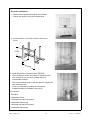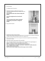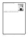
1
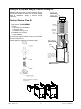
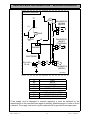
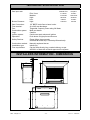
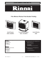
SLIMFIRE 25
FLAME FIRE
Customer Operation & Installation Manual
This appliance shall be installed in accordance with:
•
•
•
•
•
Manufacturers Installation Instructions
Local Gas Fitting Regulations
Municipal Building Codes
A.G.A. Installation code AS 5601 ‘Gas Installations’
Any other local relevant Statutory Regulation
Installation & Service must be performed by an authorised person.
This heater is NOT designed to be built directly into a combustible opening.
For combustible opening installations, a Rinnai zero clearance kit is available
from your gas appliance retailer.
Head Office Certified
Proudly a member of the A.G.A.
All of our gas products are A.G.A.
tested and approved
Distributed and serviced in Australia under a Quality
System certified as complying with ISO 9002 by
Standards Australia Quality Assurance Service
INSTALLER: MUST LEAVE THIS MANUAL WITH THE UNIT AFTER INSTALLATION
OWNER: RETAIN THIS MANUAL SAFELY, FOR FUTURE REFERENCE
LIMITED WARRANTY
As a purchaser of a high quality Rinnai product, we provide you with the following
guarantee on your new Flame Fire Heater.
Free Labour Period
Free Parts Period
FANS
1 Year
2 Years
HEAT EXCHANGER
1 Year
10 Years Pro-Rata*
ALL Other parts
1 Year
1 Year
* Heat Exchanger full replacement parts costs in the first year, reducing 10% per year thereafter.
The benefits conferred by this guarantee are in addition to all other rights and remedies
in respect of the product which you have under the Trade Practices Act and other State
and Territory Laws.
The appliance must be installed correctly, and the installation must conform to all local
regulations.
The installation must also comply with the instructions supplied by Rinnai.
The appliance must be serviced by an authorised person.
No Parts or functions should be modified or permanently removed from the heater.
Please note: General cleaning, maintenance and wear and tear are not necessarily
covered by guarantee. Calls of this nature may be chargeable.
Your Rinnai Space Heater has been approved by the Australian Gas Association, the
AGA Approval Number is located on the data plate of the appliance.
Please keep these instructions in a safe place for future reference.
PLEASE RECORD BELOW:
Your Retailer:
NAME:
ADDRESS:
TELEPHONE:
Date of Purchase:
IBF - Slimfire 25
/
- ii -
/
Issue 5 - ©Rinnai
WARNING
IMPROPER INSTALLATION, ADJUSTMENT, ALTERATION, SERVICE OR
MAINTENANCE CAN CAUSE PROPERTY DAMAGE, PERSONAL INJURY OR
LOSS OF LIFE.
INSTALLATION AND SERVICE MUST BE PERFORMED BY AN AUTHORISED
PERSON.
This manual applies to the following models only:
IBFBN/A
IBFSSN/A
IBFBL/A
IBFSSL/A
Table of Contents
LIMITED WARRANTY ............................................................................................................................ii
CUSTOMER INFORMATION - SAFETY POINTS ................................................................................. 1
CUSTOMER INFORMATION - OPERATION ........................................................................................ 2
CUSTOMER INFORMATION - IMPORTANT POINTS ......................................................................... 3
CUSTOMER INFORMATION - SPECIFICATIONS ............................................................................... 4
CUSTOMER INFORMATION - TROUBLE SHOOTING ........................................................................ 5
INSTALLERS INFORMATION - LOCATION ......................................................................................... 6
INSTALLERS INFORMATION - FLUEING ............................................................................................ 7
INSTALLATION INTO A COMBUSTIBLE OPENING ............................................................................ 9
CUSTOMER INFORMATION - INSTALLATION PROCEDURES ....................................................... 14
INSTALLERS INFORMATION - GAS CONNECTION .......................................................................... 15
INSTALLERS INFORMATION - ELECTRICAL CONNECTION ........................................................... 15
INSTALLERS INFORMATION - LOG INSTALLATION ....................................................................... 16
INSTALLERS INFORMATION - TESTING & COMMISSIONING ........................................................ 17
INSTALLERS INFORMATION - WIRING DIAGRAM .......................................................................... 18
TECHNICAL SPECIFICATION ............................................................................................................ 19
INSTALLERS INFORMATION - DIMENSIONS ................................................................................... 19
INSTALLATION / COMMISSIONING CHECKLIST ............................................................................. 20
INSTALLERS / GAS FITTER DETAILS ............................................................................................... 20
CUSTOMER CONTACTS .................................................................................................................... 21
IBF - Slimfire 25
- iii -
Issue 5 - ©Rinnai
CUSTOMER INFORMATION - SAFETY POINTS
Do not restrict the warm air discharge by
placing articles in front of the heater.
This appliance must not be used for any
purpose other than heating.
Do not spray aerosols whilst the heater
is operating. Most aerosols contain
butane gas, which can be a fire hazard if
used near the heater when it is in use.
Young children should be supervised at
all times. Hand or body contact with the
louvres must be avoided.
Do not allow young children or the infirm
to sleep directly in front of the heater.
Do not allow anyone to sit on or lean
against the appliance.
Do not allow anyone to post articles
through the louvres.
Do not allow curtains or other flammable
or combustible materials to come into
contact with the heater.
DO NOT PLACE ARTICLES ON OR AGAINST THIS APPLIANCE.
DO NOT USE OR STORE FLAMMABLE MATERIALS NEAR THIS APPLIANCE.
DO NOT SPRAY AEROSOLS IN THE VICINITY OF THIS APPLIANCE WHILST IT IS IN OPERATION.
IBF - Slimfire 25
-1-
Issue 5 - ©Rinnai
CUSTOMER INFORMATION - OPERATION
IMPORTANT: You must read and • To turn the heater off
understand these instructions fully
Press and release the buttons in order from
before operating the heater.
left to right until all 3 buttons are in the “OFF”
(OUT) position. The fan will stop when the
The controls are located on the lower
heater cools down.
left hand side of the heater.
Ensure all burners are extinguished.
• Ignition
• Fan operation
Press the right hand control button firmly. This
operates the built-in safety device and starts
the electronic spark. The front burner and
pilot will ignite. Check that the burner has lit
and continue to hold the button down for up to
15 seconds. The spark will continue while the
button is held down.
The fan will operate authomatically when the
heater warms up, and will stop when the
combustion chamber cools.
When the heater is on the ‘high’ setting the fan
will operate on high speed when the heater is
hot.
If the burner does not remain alight, push the When the heater is on the ’low’ or ‘medium’
button again and release it. This will return it heat setting, the fan will operate on slow
to the ‘OFF’ position. Wait 30 seconds, then speed when the heater is hot.
repeat the ignition procedure.
When the heater is on its lowest setting the fan
(The ignition button must be in the “OFF” may turn off as the heater cools and restart
position before attempting re-ignition).
when warm again.
HIGH
MED
NOTE: If there is a power failure when
the heater is in operation the overheat
protection may shut off the gas to
protect the heater. In the event of a
power failure, turning the heater to its
lowest setting may allow the heater to
continue
operating
without
overheating.
IGN
~
LOW
• To adjust the heat
Press the control buttons in order from right to
left, this will ignite additional burners as shown
in diagram below.
There is no need to hold the buttons for 15
seconds when increasing the heat.
The fan will not work without electrical power.
The fan may continue to operate on slow
speed when the burners have been
extinguished until the heater cools down.
Buttons
Fan
1. Ignition / Low 7.7 MJ/h (NAT)
9 MJ/h (Propane)
Low
2. Medium
14.2 MJ/h (NAT)
15.8 MJ/h (Propane
Low)
3. High
25 MJ/h (NAT)
25 MJ/h (Propane)
High
IBF - Slimfire 25
-2-
Burner pattern
Issue 5 - ©Rinnai
CUSTOMER INFORMATION - IMPORTANT POINTS
Before installing this product, please read this manual carefully.
Unpack the heater and check for damage. DO NOT INSTALL DAMAGED HEATER.
If the heater is damaged, contact your supplier for advice. Before installing the heater,
check the label for the correct gas type (see rating plate, front right hand side of
bottom panel). Refer to local gas authority for confirmation of the gas type if you are
in doubt.
Included in the carton
Customer operation information, roll of sealing foam, ceramic log set and granules.
IMPORTANT
Before using this product, please read this manual carefully to make sure of proper
use of the product.
The user shall be advised that appliances incorporating a live fuel effect, and designed
to operate with luminous flames, may exhibit slight carbon deposits.
1. The appliance must be installed in accordance
manufacturers agent or similarly qualified
with the local gas and electrical authority
person in order to avoid a hazard.
regulations.
13. Do not allow articles to be posted through the
2. For information on gas consumption, see data
louvres or openings.
plate on the appliance.
14. Do not spray aerosols near this heater whilst it
3. Ensure that the area in which the appliance is
installed has adequate fixed ventilation, this
fixed ventilation must be provided as per
AS5601.
4. DO NOT connect to an LPG/Propane Gas
cylinder indoors.
is in use. Most aerosols contain butane gas
which can be a fire hazard if used near this
heater when in use. Use of aerosols, paint,
polishes etc whilst this heater is in use may
cause unpleasant smells.
5. This appliance must not be installed where
curtains or other combustible materials could
come into contact with it. In some cases
curtains may need restraining.
15. Do not operate/install this heater in places
where painting is taking place, or in places
such as hair dressing salons, where there may
be a lot of fluff and dust, and where aerosols
are used.
6. This appliance is not designed to be built
directly into a combustible opening.
16. Do not unplug the heater while it is still in
operation or the fan is operating.
7. Heater must not be located below a power
socket-outlet.
17. Do not turn off heater by unplugging it at the
wall.
8. The local gas and electrical authorities will be
able to advise on local regulations.
18. Do not place articles on or against this
appliance.
9. Heat emanating from the front of this appliance 19. Do not place clothes racks etc. directly in front
of the heater.
may over time affect the appearance of some
materials used for flooring such as carpet, vinyl, 20. Do not store flammable materials near the
cork or timber. This effect may be amplified if
heater. Combustible materials must not be
the air in the room contains cooking vapours or
allowed where the heater could ignite them.
cigarette smoke. To avoid this possibility, it is 21. The heater may emit smoke when first started
recommended that a mat be placed in front of
which may take up to 2 Hours to disappear.
the appliance, extending at least 750 mm in
This is part of the burning in process and
front of it.
normal, ensure adequate ventilation during
10. The appliance is not intended for use by young
this period.
children or infirm persons without supervision. 22. The guard is fitted to this appliance to reduce
11. Young children should be supervised to ensure
they do not play with the appliance.
the risk of fire or injury from burns and no part
of it should be permanently removed, for
protection of young children or the infirm, this
secondary guard is required.
12. If the supply cord, gas hose or glass are
damaged or require replacing, they must be
replaced by the manufacturer or the
IBF - Slimfire 25
-3-
Issue 5 - ©Rinnai
CUSTOMER INFORMATION - SPECIFICATIONS
Model:
Slimfire
Slimfire
Description:
Inbuilt Radiant/Convector, glass fronted, ceramic log space
heater with forced convection and natural draft flue system.
Output:
18 MJ/hr
Gas Control:
Push button combination control valve
Burners:
Ember bed and flame burner
Warm Air Discharge:
Top front louvres
Flue:
Natural draft rectangular flue
Ignition:
Electronic spark
Power Supply:
240 V 50 Hz
Rating Plate location:
Bottom panel, front right hand side
Weight:
39 Kgs.
IBF - Slimfire 25
IBFBN/A (NG)
IBFBL/A (Propane)
-4-
Issue 5 - ©Rinnai
CUSTOMER INFORMATION - TROUBLE SHOOTING
SYMPTOM
CAUSE
SOLUTION
•
No power present
•
•
•
No gas present
Power cut
•
•
•
•
Air in gas supply pipe
Ignition failure
•
•
Smell of gas
•
Leaking gas
•
Turn off gas at meter or LPG /
Propane cylinder and call
installer.
Fan not working
•
Heat Switch not activated
•
•
No power present
•
•
Allow heater to run on ‘high’ for
about 5 minutes.
Ensure power cord is plugged in
and turned on.
Check power supply.
Burner will not light
Ensure power cord is plugged in
and turned on.
Ensure gas supply is turned on.
Re-ignite when power has been
restored.
Purge air (installer).
Repeat lighting procedure (refer
page 2)
Small soot deposits
•
Normal operation
•
No action required.
Severe soot deposits
forming on logs or glass
•
•
•
Inadequate flue system
Incorrect gas pressure
Log misalignment
•
Call Rinnai Service Department
/ Agent.
Condensation on glass
•
Normal operation
•
Allow heater to warm up.
Streaky lines on glass
•
Normal operation
•
Call Rinnai Service Department
/ Agent.
• NOTE:
If you have any other faults or problems, please refer to your installer or a Rinnai Customer
Care Centre Consultant on 1300 366 388.
• IMPORTANT:
Do not remove any panels or attempt to carry out any service work other than that mentioned
in the trouble shooting chart.
• SERVICE:
Rinnai has a service and spare parts network with personnel who are fully trained and equipped
to give the best service on your Rinnai appliance.
If your appliance needs service, please ring one of the service contact numbers located on the
back of this instruction booklet.
Rinnai recommends that this appliance should be serviced annually by a qualified service
technician, including inspection of the flue system.
IBF - Slimfire 25
-5-
Issue 5- ©Rinnai
INSTALLERS INFORMATION - LOCATION
The following pages contain information 9. This heater must be mounted on a hearth
not less than 50mm thick and at least the
relating to Installation and Service.
width and depth of the heater.
Installation and Service must be carried
out by an authorised person only.
10.A gas appliance must not be connected to
a chimney flue serving a separate solidfuel burning appliance.
When positioning the heater, the main
points governing the location are:
1. Flue connection and terminal to comply
with AS5601.
2. Warm air distribution
11.Before installing the heater, inspect the
chimney, flue piping and/or solid fuel
burning fire place and remove any
combustible materials.
12.A zero clearance kit is available from your
gas appliance retailer for installations into
a combustible enclosure.
3. Ensure that the area in which the
appliance is installed has adequate fixed
ventilation, this fixed ventilation must be
provided as per AS5601 Clause 5.4 to
5.4.5.
• Mantles
4. The heater must not be installed where
curtains or other combustible materials
could come into contact with it. In some
cases, curtains may need restraining.
A mantle is allowable providing that it is
outside the minimum clearances and the
distance it protrudes is no more than half
the distance it is above the heater.
See below for minimum clearances required. See diagram below.
300mm
(Example dimensions shown in brackets).
300mm
300mm
Note that side and vertical
clearances are measured
from the edge of the glass.
50 maximum
at 300 above
X (200)
1000mm
½X+50
(150)
300 mm Minimum
from top of glass
5. The heater is not designed to be built into
bookcases or shelves or any
combustible opening.
6. This heater must be mounted on a hearth
not less than 50mm thick and at least the
width and depth of the heater.
7. A gas appliance must not be
connected to a chimney flue serving a
separate solid-fuel burning appliance.
8. Before installing the heater, inspect the
chimney, flue piping and/or solid fuel
burning fire place and remove any
combustible materials.
IBF - Slimfire 25
-6-
Issue 5 - ©Rinnai
INSTALLERS INFORMATION - FLUEING
Installation in a Fireplace
1. Check Dimensions of Fireplace
Check dimensions of fireplace and if necessary bring
them to the dimensions shown.
•
If the fireplace opening is larger than the heater, a
100mm wide decorative surround Part no. for the
External top panel FLFRSEXT (Black only) and are
available from your local gas appliance retailer.
2. Check conditions of fireplace/chimney
The chimney must be physically checked first and
must meet the following set criteria along with local
regulations. Failure to meet these criteria will not only
void the product warranty but may affect the
performance of the product.
595 mm Minimum Width
700 mm Maximum Width
550 mm Minimum Height
630 mm Maximum Height
•
Minimum clearance
between flue spigot
& back of fireplace
75 mm
Hearth 50 mm Minimum
a):
All loose/broken bricks must be replaced or
repaired ensuring the chimney is of sound
construction and does not leak.
b):
Any under floor air supply to the fireplace must be completely sealed off to prevent
secondary air draw.
c):
Total flue length MUST NOT be less than 3 metres and flue cowl must terminate above
the chimney in accordance with AS5601.
d):
The chimney must be swept clean and be free of soot and creosote that may have built up
if previously used for a solid fuel fire.
e):
The hearth surface must be flat and level to support the entire heater.
If the heater is not properly supported noise and vibration may result.
3. Install Flue
For installations into a masonry fireplace a Rinnai Flexible Flue system is required. Rinnai rigid
flame fire flueing is not suitable. Assemble and connect flue in accordance with the instructions
supplied with the flue kit, please refer to the detailed instructions which are included in the
Flexliner Flue Kit.
4. Apply sealing strips to back of heater
SEALING STRIPS
• Peel protective backing off the foam strips supplied with
the Heater.
• Attach strips to rear of casing as shown. The strip is
intended to form a seal between the heater and the
fireplace.
• If an adequate seal cannot be formed with this strip an
other means of sealing must be used. (eg.non combustible
insulation), between the fireplace and the heater body.
IBF - Slimfire 25
-7-
Issue 5 - ©Rinnai
Flueing in a fireplace using a Flexliner flueing kit.
Installation with a flue liner is required when a chimney
will no longer substitute as a flue, such as when leakage
is found during the smoke test, or where the chimney
height is inadequate. Refer to Rinnai Flueing
Instructions.
Chimney Cowl
Chimney Plate
Flexliner Slimfire Flue Kit
Order code: FLEXLINER03
Adaptor
Contains:
- 1 x Chimney Cowl & Adaptor
- 1 x Chimney Plate
- 1 x Flexible Chimney Liner
(extendable to 5.0 metres)
- 1 x Flue Adaptor
- 1 x Appliance Adaptor
If the chimney height excedes 5.0 metres, use Voumard
900 x 100 snap-lock flue
(code: 72-0583) to extend to the desired length.
Flexable
Chimney
Liner
Appliance Adaptor
Slimfire
Heater
Note: Ensure maximum
vertical rise before any
change of direction and
avoid sharp bends as this
will restrict the chimneys
ability to draw.
Fitting of the Appliance Adaptor
to the heater
IBF - Slimfire 25
-8-
Issue 5 - ©Rinnai
INSTALLATION INTO A COMBUSTIBLE OPENING
Zero Clearance Installations
Rinnai understands that not all households have existing masonry fireplaces which previously limited the
products available for installation. Rinnai offers the option of installing the Slimfire into a decorative
fireplace in single storey or two storey home. All you need is a flat wall which can be either external or
internal wall and a zero clearance box. A Rinnai Rigid flue MUST also be installed (Part No. FLFKIT05 /
FLFTWKIT). Flexible flue kits are not suitable.
The Zero clearance box can be installed hard against the combustible timber framework of the mock
fireplace due to the air gap created beneath the appliance with the use of the plinth panel, and the air gap
between the outer panel of the Flame fire and the Rinnai Zero clearance box. (Part No. ZEROR). Only this
Zero clearance box must be used for these installations.
Rinnai Flame Fire Rigid Flueing allows the air to be drawn in through the louvres in the plinth panel, pass
around the sides and back of the Flame Fire heater and be drawn away through the outer skin of the flue.
The resulting air flow will keep the Zero clearance box panels at a safe operating temperature.
Refer to Rinnai Flueing Installation Manual for Rinnai Flame Fire Heaters for details of FLFKIT05 and
FLFTWKIT in conjunction with Zero Clearance kit installation.
Available flueing options as follows:
OBSTRUCTION
A
HEATER
IBF - Slimfire 25
ZERO
CLEARANCE
BOX
ZERO
CLEARANCE
BOX
B
ZERO
CLEARANCE
BOX
HEATER
-9-
C
HEATER
Issue 5 - ©Rinnai
Steps for Installation:
1. Determine the preferred location of the heater.
• Check roof space for any flue obstructions.
2. Construct frame in accordance with the dimensions
shown:
675mm
370 mm
685mm
3. Install Rinnai Zero Clearance Box (ZEROR)
• ‘Zero clearance’ means the panels of metal from the
zero clearance box can be in contact with any
combustible material.
• The hearth surface must be flat and level to support the
zero clearance box.
If the zero clearance box base is not properly
supported noise and vibration may result.
Kit contains:
- Zero Box
- Supporting Plinth
- Complete decorative Surround
- Installation Instructions
- Complete decorative Surround
- Installation Instructions
IBF - Slimfire 25
- 10 -
Issue 5 - ©Rinnai
l
4. Run gas supply.
For details please see page 15.
5. Install Rinnai Flame Fire Rigid Flueing as per the
instructions supplied with the flue kit, taking careful note
of the following:
Flue termination above the roof must comply with
AS5601.
Vertical flue length must be no less than 3.0
metres.
The inner and outer flues must be supported
independently of the heater to comply with
AG5601.
6. Apply plaster and paint.
7. Assemble the plinth and base supports.
Slide the plinth and base supports and heater into the zero clearance box, making sure the plinth is
located correctly between the heater and the zero clearance box.
8. Slide the slip socket onto the inner flue spigot of the heater and tighten to seal. Refer flueing
instructions for details.
9. Attach gas supply, purge supply of air and debris
Note: All foreign materials such as filings must be purged from the gas supply, as
before connection as they may damage the gas controls.
NOTE: on completion of work a gas leak test must be carried out.
Use a soapy solution on all gas connections. Leaks will be visible when the
soapy solution forms bubbles.
When finished wipe soapy solution with a rag to remove residue.
IBF - Slimfire 25
- 11 -
Issue 5 - ©Rinnai
10.Install top decorative surround to face of fireplace.
11. Log Installation - for Log Installation details, please refer to page 16.
12.Commissioning - for Commissioning details, please refer to page 17.
IBF - Slimfire 25
- 12 -
Issue 5 - ©Rinnai
Vertical Twin Skin Single Storey Flue Kit 05
Order code: FLFKIT05
Contains:
- 2 x 900mm Powder Coated Twin Skin Flue Pipes
- 1 x 450mm Powder Coated Outer Flue
- 2 x 900mm Gal Inner Flue Pipes
- 1 x Powder Coated Ceiling Ring *
- 1 x Chimney cowl
- 1 x Sleeve Clamp
* item not required for use in zero clearance installations.
Alternately when installing a heater into a two storey premises use the following kit.
Thru-Wall Two Storey Flue Kit
Order code: FLFTWKIT
Contains:
- 1 x 900mm Powder Coated Twin Skin Flue Pipe
- 1 x 45× Black Twin Skin Offset and Wall Plate
- 1 x 45× Gal Twin Skin Offset and Wall Plate
- 4 x 1200mm Gal Twin Skin Pipe
- 1 x Gal Ceiling Plate
- 1 x Chimney cowl
- 1 x Sleeve Clamp
Note: Overall flue length approximately 6.3m
(plus height of appliance plus 765mm)
Maximum wall thickness 270mm
(Full installation instructions are supplied with all accessory kits).
IBF - Slimfire 25
- 13 -
Issue 5 - ©Rinnai
CUSTOMER INFORMATION - INSTALLATION PROCEDURES
• Preparation
• Installation
Refer to the Location and Flueing sections
on pages 10-12 to make sure the decorative
fireplace cavity is suitable for installation
before continuing.
For installation into a non-combustible fire
place the foam strips supplied must be
attached to the heater as shown (5) to
provide a seal around the fire place (if this
does not provide adequate seal an
alternative must be used).
Place the heater on a flat surface.
Remove the three screws holding the front
fascia in place. (1)
Pull the bottom of the facia forward until clear
of the gas control buttons and lift up to
remove from frame.
Remove the two screws holding the top glass
retainer in place and lift off glass retainer. (2)
Loosen the two screws holding the lower
glass retainer in place and remove glass
panel. (3)
Remove the barrel elbow from the gas
connection bracket on the base of the heater
at the front right hand side. Make sure that
the gas flare fitting and gas supply pipe are
clean and free of damage and fit together
ready for fitting to the heater. (4)
Insert the heater into the cavity. Take care
when inserting the gas supply tube into the
heater not to damage the tube or any of the
components inside the heater.
There are four levelling screws (6) in the
base of the heater held in place with
locknuts. If the heater does not sit flat when
in place, it may be necessary to adjust these.
The front screws are accessible with the front
of the heater removed. If adjustment of the
rear feet is required the burner assembly and
gas control will need to be removed.
Once the heater is sitting flat attach it to the
wall using the four holes (two per side) in the
front flanges.
2
7
5
10
3
11
6
8
9
4
1
IBF - Slimfire 25
- 14 -
Issue 5 - ©Rinnai
INSTALLERS INFORMATION - GAS CONNECTION
• Run gas supply
For pipe sizing, refer to your local
gas installation codes. Copper
supply should be run leaving a
flared connection at the position
shown.
260
• Purge supply of air and debris
All foreign materials such as filings
must be purged from the gas
supply, as they may cause the gas
control valve to malfunction.
79
43
½" BSPF MALE FLARE
• Fit heater into place
When the heater is in place and
properly secured, attach the gas
supply to the supplied barrel union
and tighten.
NOTE: On completion of work a gas
leak test must be carried out.
Use a soapy solution on all gas
connections. Leaks will be visible when
the soapy solution forms bubbles. When
finished, wipe soapy solution with a rag
to remove residue.
INSTALLERS INFORMATION - ELECTRICAL CONNECTION
The heater has a power cord with a three
pin plug supplied. The power cord
passes through the slot in the lower left or
right hand side of the heater front
assembly.
Rinnai recommends that the heater be
plugged into a 240V,10A earthed power
point. The power point must be a
minimum of 300 mm to the side of the
heater (it must not be above the heater).
Alternatively - unit can be direct wired if
the power supply is to be concealed.
IBF - Slimfire 25
POWER CORD
RUBBER GROMMET
Consult a qualified electrican if direct
wiring is required. As it must comply
to AS5601.
- 15 -
Issue 5 - ©Rinnai
INSTALLERS INFORMATION - LOG INSTALLATION
Step. 1: Preparation of the Logset
Fig. 1
Remove the logset and granule packet
from their packaging.
To achieve the correct location of the
Logset, hold the Logset as shown
(Fig. 1).
Step. 2: Initial positioning, locating
the Logset in the combustion
chamber
Fig. 2
Tilt the back of the Logset upwards
locating the front feet (1.) behind the
unpainted inner horizontal steel lip (2.)
(Fig. 2).
Ensure the Logset sides do not touch the
combustion chamber panel walls.
Step. 3: Final positioning, setting the
Logset into the combustion chamber
Fig. 3
Rotate the back of the Logset down using
the location of the front feet (3.) as pivot
points (Fig. 3).
Step. 4: Correct Logset installation
This image illustrates how a correctly
installed Logset will look on completion
(Fig. 4).
Step. 5 Adding granules
Fig. 4
Carefully PLACE (do not pour) sufficient
granules onto the front burner only.
Avoid pushing the granules under the log
or spilling over the front of the burner.
Step. 6 Replacing Glass
Replace the glass ensuring the joint in the
glass sealing tape is at the bottom.
IBF - Slimfire 25
- 16 -
Issue 5 - ©Rinnai
INSTALLERS INFORMATION - TESTING & COMMISSIONING
Testing Procedure
Turn gas supply on and plug the unit into
the power supply. (Caution: 240V).
To check burner pressure
It is the responsibility of the installer to check
that under normal operating conditions of the
appliance, all flue gases are exhausted to the
outside atmosphere and that there is no
spillage of combustion gases into the room.
Please refer to AS 5601.
• Refer to Data Plate; the Technical • Commissioning
Specification section in this manual.
Installation and Commissioning
Checklist
• Remove front cover panel.
• Remove test point screw and attach Complete the installation checklist and
manometer to test point, the test point the installer details on page 20 and make
sure that this instruction book is left with
is on the front injector block.
the customer.
• Light heater, turn to High heat setting
and check pressure.
Instruct Customer on the use of unit
• If adjustments are necessary, the
regulator is situated on the front of the
gas control and should be set to the
pressures on the data-plate.
• After checking pressure, turn the unit
off, remove manometer and replace
test point screw.
The guard on this appliance conforms to
A.G.A. requirements. It is designed to prevent
the risk of injury from burns and no part of it
should be permanently removed. IT DOES
NOT GIVE FULL PROTECTION TO YOUNG
CHILDREN OR THE INFIRM.
• Turn the heater on and off a few times
to check ignition.
• When you are satisfied that the heater
is working correctly, reassemble
panels.
• All burner aerations are factory preset
and cannot be adjusted.
• If you are unable to get the unit to
operate
correctly,
refer
to
Troubleshooting on page 5 before
contacting your local service contacts
on the back page.
• It may take approximately 2 hours of
operation for the logs to achieve their
full flame pattern and glow.
2.1.23 A primary guard shall be fitted in
the following circumstances:
a) To all external surfaces which fail
the fabric drape test (see Clause 3.3.4).
b) To all external surfaces which
during operation reach a temperature in
excess of 95°C above ambient, except
working surfaces and surfaces within
25 mm of a working surface.
c) To all heat sources and external
surfaces within 25 mm of working
surfaces which during operation reach
a temperature in excess of 200°C above
ambient.
d) To all working surfaces with an open
area less than 85% of the total area of
the working surface, which during
operation reach a temperature in
excess of 200°C above ambient.
• During the initial burning in period, The manufacturer reserves the right to
some smoke and smell may be change or modify specifications without
experienced, the heater should be run notice.
on the high position in a well
ventilated room until these dissipate.
IBF - Slimfire 25
- 17 -
Issue 5 - ©Rinnai
INSTALLERS INFORMATION - WIRING DIAGRAM
WIRING DIAGRAM
TC
FAN
BL
(+)
(-)
R
FAN SWITCH
HI/ LOW
(MICRO)
1 BL
2 R
3 W
OHS
W
SV
W
FAN SWITCH
ON/OFF
(THERMAL)
2 BR
1 BL
+ SPARKER
BL
ELECTRODE
W
BL
BR
220~240 v
50 Hz
2
1
BL
W
G/Y
1 BL
2 W
IGN SWITCH
(MICRO)
PN 10153
R
BL
BR
W
G/Y
RED
BLUE
BROWN
WHITE
GREEN YELLOW
OHS
SV
TC
OVER HEAT SWITCH
SOLENOID VALVE
THERMOCOUPLE
If the supply cord is damaged or requires replacing, it must be replaced by the
manufacturer or the manufacturers agent or similarly qualified person in order to avoid
a hazard. The supply cord must only be replaced with a genuine Rinnai spare part.
IBF - Slimfire 25
- 18 -
Issue 5 - ©Rinnai
TECHNICAL SPECIFICATION
Gas input rate:
Natural Gas
7.7 MJ/hr
Pilot / front:
14.2
MJ/hr
Medium:
25 MJ/hr
High:
8 MJ/hr
Low:
0.92 kPa
High:
1/2” BSPF male flare to barrel union
43 x 245 rear discharge
Tangential 2 speed, power rating 28 Watts
Multi port burner
Ceramic
Continuous spark electronic ignition
Push button to light pilot and burners
Flame failure thermocouple
Overheat Bi-metal strip / Fan delay Bi-metal strip
Naturally aspirated burner
Inbuilt only
Can be flued directly into a sealed chimney as per
AS 5601 or fitted with a Rinnai approved flue system
Burner Pressure:
Gas Connection:
Flue terminal:
Fan:
Combustion system
Logs:
Ignition system:
Operation:
Safety Devices:
Combustion method:
Installation type:
Flue requirement:
Propane
9 MJ/hr
15.8 MJ/hr
25 MJ/hr
9 MJ/hr
2.0 kPa
INSTALLERS INFORMATION - DIMENSIONS
35
25
750
645
310
277
528
582
IBF - Slimfire 25
- 19 -
Issue 5 - ©Rinnai
INSTALLATION / COMMISSIONING CHECKLIST
(To be completed by certified Gas Installer)
NO
YES
Model: _______________________________
1. Was a fireplace inspection carried out?
(i.e. clearances, combustibles etc).
2. Was a Rinnai flue system installed in accordance with the instructions?
3. Has specified gas pressures been checked and set?
4. Are decorative logs located correctly?
5. Have ember granules been placed and free of dust and powder?
6. Has the appliance been test fired for correct operation?
(All Burners light without delay)
7. Is the end-user fully aware of operating procedure?
INSTALLERS / GAS FITTER DETAILS
Company name:
____________________________________________________
Installers name:
____________________________________________________
Address:
____________________________________________________
____________________________________________________
____________________________________________________
Phone:
__________________ Mobile: __________________________
Certificate of Compliance / Certification Number:__________________________
(* where applicable)
Authorised Persons – Licence Number: _______________________________
Signed:________________________
IBF - Slimfire 25
Date:___________________________
- 20 -
Issue 5 - ©Rinnai
CUSTOMER CONTACTS
The Rinnai Flame Fire Heater Family
Inbuilt Royale
IB35 / IB35ETR
Australia Pty. Ltd.
Head Office
Freestanding Royale
FS35 / FS35ETR
Inbuilt Slimfire
IB25
ABN 74 005 138 769
Internet: www.rinnai.com.au E-mail: [email protected]
10-11 Walker Street,
Braeside, Victoria 3195
P.O. Box 460
Tel: (03) 9271 6625
Fax: (03) 9271 6622
National Help Line
Spare Parts & Technical Info
Tel: 1300 366 388*
Fax: 1300 300 141*
*Cost of a local call Higher from mobile or public phones.
Internet: www.rinnai.co.nz E-mail: [email protected]
Head Office, New Zealand
691 Mt. Albert Road,
Royal Oak, Auckland
P.O. Box 24-068
Tel: (09) 625 4285
Fax: (09) 624 3018
IBF - Slimfire 25
24 Hour Service
Tel: 0800 746624 (0800 Rinnai)
- 21 -
P/N 9784 Issue C (02-106) Issue 5 - 28/8/07