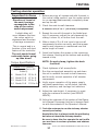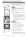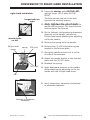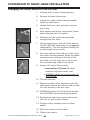
1
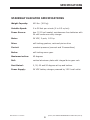
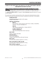
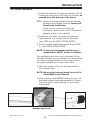
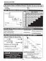
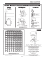
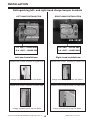
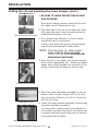
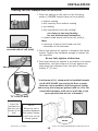
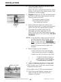
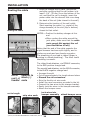
SRE-2000
ELECTRA-RIDE™ ELITE
STAIRWAY ELEVATOR
COMMERCIAL
Technical Service email: [email protected]
www.bruno.com
DEALER:
INSTALLATION MANUAL
MAN-2000-1
11-14-2007
1780 EXECUTIVE DR., P.O. BOX 84, OCONOMOWOC, WI 53066 USA
TELEPHONE:(262) 567-4990
FAX: (262) 953-5501
1-800-882-8183
IMPORTANT NOTES
NOTE: P
lease locate the metal
templates for drilling the
mounting holes for the
lower charge bracket.
This stairway elevator is
FOR INDOOR USE ONLY
in enclosed heated locations
above 35°F (2°C).
The warranty for the Electra-Ride™ Elite
Stairway Elevator is
rendered null and void
if the unit is installed by
anyone other than an authorized Bruno dealer.
Electra-Ride™ Elite is a trademark of Bruno Independent Living Aids, Inc.®
©2007,2001 BRUNO INDEPENDENT LIVING AIDS, INC.®
2
SRE-2000C 11-14-2007
TABLE OF CONTENTS
Important Notes. . . . . . . . . . . . . . . . . . . . . . . . . . . . . . . . . . . . . . . . . . 2
Regulatory Information . . . . . . . . . . . . . . . . . . . . . . . . . . . . . . . . . . . . . 4
Specifications. . . . . . . . . . . . . . . . . . . . . . . . . . . . . . . . . . . . . . . . . . . . 5
Carton Contents. . . . . . . . . . . . . . . . . . . . . . . . . . . . . . . . . . . . . . . . . . 7
Tools Needed for Installation . . . . . . . . . . . . . . . . . . . . . . . . . . . . . . . . . 8
INSTALLATION
Fitting the Rail. . . . . . . . . . . . . . . . . . . . . . . . . . . . . . . . . . . . . . . . 9
Application Guide. . . . . . . . . . . . . . . . . . . . . . . . . . . . . . . . . . . 10-11
Distinguishing Between Right- and Left-Hand Charge Bumper Brackets. . 12
Cutting the Rail and Installing Lower Bumper . . . . . . . . . . . . . . . 13-14
Placing the Rail Clamps and Rail Sections. . . . . . . . . . . . . . . . . . 15-19
Routing the Cable . . . . . . . . . . . . . . . . . . . . . . . . . . . . . . . . . . . . 20
Mounting the Carriage, Upper Bumper and Upper End Cap. . . . . . . . 21
Adjusting the Carriage Angle. . . . . . . . . . . . . . . . . . . . . . . . . . . . . 22
Mounting the Footrest Assembly . . . . . . . . . . . . . . . . . . . . . . . . . . 23
Mounting the Seat Assembly. . . . . . . . . . . . . . . . . . . . . . . . . . . 24-25
Mounting the Final Limit Ramp Kit. . . . . . . . . . . . . . . . . . . . . . . . . 26
ELECTRICAL
Circuit Breaker . . . . . . . . . . . . . . . . . . . . . . . . . . . . . . . . . . . . . . 21
Infrared Call/Send Transmitter . . . . . . . . . . . . . . . . . . . . . . . . . . . 27
Mounting the Commercial Call/Send Transmitters . . . . . . . . . . . . . . 28
Testing the Call/Send Transmitters. . . . . . . . . . . . . . . . . . . . . . . . . 29
Circuit Board Diagnostics . . . . . . . . . . . . . . . . . . . . . . . . . . . . . 30-31
Learning the IR Transmitter . . . . . . . . . . . . . . . . . . . . . . . . . . . 32-33
Battery Charger. . . . . . . . . . . . . . . . . . . . . . . . . . . . . . . . . . . . 34-35
LUBRICATION. . . . . . . . . . . . . . . . . . . . . . . . . . . . . . . . . . . . . . . . . . . 36
TESTING ELEVATOR OPERATION. . . . . . . . . . . . . . . . . . . . . . . . . . . . . . 37
CONVERSION TO RIGHT-HAND INSTALLATION
Electrical and Mechanical Operations. . . . . . . . . . . . . . . . . . . . . 38-39
Changing the Rocker Switch to the Left Arm. . . . . . . . . . . . . . . . . . 40
ADJUSTMENTS
Seat Height Adjustment. . . . . . . . . . . . . . . . . . . . . . . . . . . . . . . . 41
Speed Control Adjustment . . . . . . . . . . . . . . . . . . . . . . . . . . . . . . 41
MAINTENANCE
Vacation/Long-Term Storage. . . . . . . . . . . . . . . . . . . . . . . . . . . . . 42
Yearly Maintenance Operations. . . . . . . . . . . . . . . . . . . . . . . . . . . 43
OVERSPEED. . . . . . . . . . . . . . . . . . . . . . . . . . . . . . . . . . . . . . . . . . . . 44
WIRING SCHEMATIC. . . . . . . . . . . . . . . . . . . . . . . . . . . . . . . . . . . . . . 45
TROUBLESHOOTING . . . . . . . . . . . . . . . . . . . . . . . . . . . . . . . . . . . . 46-47
EXPLODED VIEWS. . . . . . . . . . . . . . . . . . . . . . . . . . . . . . . . . . . . . . 48-54
WARRANTY. . . . . . . . . . . . . . . . . . . . . . . . . . . . . . . . . . . . . . . . . . . . . 55
SRE-2000C 11-14-2007
3
©2007,2001 BRUNO INDEPENDENT LIVING AIDS, INC.®
REGULATORY INFORMATION
CSA CERTIFICATION
®
208135
C
US
The "C" and "US" indicators adjacent to the
CSA Mark signify that the product has been
evaluated to the applicable CSA and ANSI/UL
Standards, for use in Canada and the U.S.,
respectively. This "US" indicator includes products eligible to bear the "NRTL" indicator. NRTL,
i.e. National Recognized Testing Laboratory, is
a designation granted by the U.S. Occupational
Safety and Health Administration (OSHA) to
laboratories which have been recognized to
perform certification to U.S. Standards.
Installation of this lift is intended to be conducted in accordance with applicable
sections of ANSI/ASME A18.1 and the National Electric Code NFPA 70.
MATERIAL SAFETY DATA SHEETS
Material safety data sheets (MSDS) on materials used on this unit may be requested through
the Bruno Technical Service Department.
©2007,2001 BRUNO INDEPENDENT LIVING AIDS, INC.®
4
SRE-2000C 11-14-2007
SPECIFICATIONS
STAIRWAY ELEVATOR SPECIFICATIONS
Weight Capacity:
400 lbs. (181 kg)
Variable Speed:
0 to 28 feet per minute (0 to 8.5 m/min)
Power Source:two (2) 12-volt sealed, maintenance-free batteries with
24-volt continuous-duty charger
Motor:
24 VDC, 2-pole, 1.02 hp
Drive:
self-locking gearbox, rack-and-pinion drive
Control:
constant pressure (armrest and 2 transmitters)
Brake:
self-locking worm gear
Maximum incline:
45 degrees
Rail:vertical aluminum plate with integral drive gear rack
Seat Swivel:
0, 30, 60 and 90 degrees at top and bottom
Power Supply:24 VDC battery charger powered by 120 V wall outlet
SRE-2000C 11-14-2007
5
©2007,2001 BRUNO INDEPENDENT LIVING AIDS, INC.®
INTRODUCTION
Thank you for purchasing a Bruno SRE-2000C ELECTRA-RIDE™ ELITE STAIRWAY
ELEVATOR.
Be sure to check the carton contents for shipping damage as soon as the cartons are received.
Also, verify the contents against the packing list BEFORE leaving the shop for
the installation site.
Report any discrepancies to Bruno Independent Living Aids immediately by
calling 1-800-882-8183.
Reading through the installation manual before installing the
Stairway Elevator will help you install the unit more quickly and
avoid the frustration of arriving at the installation site only to discover that you are missing a critical tool or piece of equipment.
Best wishes to you and your customer.
©2007,2001 BRUNO INDEPENDENT LIVING AIDS, INC.®
6
SRE-2000C 11-14-2007
CARTON CONTENTS
CHECK TO BE SURE THAT YOU HAVE ALL OF THE COMPONENTS BEFORE
BEGINNING AN INSTALLATION.
CHECK CARTON CONTENTS FOR SHIPPING DAMAGE IMMEDIATELY UPON
RECEIPT. Damage claims must be filed within 21 days by the Dealer, not the Manufacturer. Bruno Independent Living Aids cannot be responsible for shipping damage.
The ELECTRA-RIDETM ELITE is shipped in 5 or 6 cartons (depending upon the number
of rails ordered).
For specific part numbers and quantities of the components indicated below, please
refer to the pertinent exploded view and bill of materials at the back of this manual.
CARRIAGE BOX
complete carriage assembly with jumper
remote control box
INSTALLATION BOX
BOX A
front clamps, clamp spacers and shims, screws, nuts/bolts/
washers, rail joint hardware kit
BOX B
rear clamps, grease tube, charge cable kit
bumper assembly #1
bumper assembly #2
final limit assembly
right rail end cap and left rail end cap
SEAT BOX
battery charger assembly
seat assembly
footrest assembly
front cover assembly
charger mounting strap, plate and screws
RAIL BOX
rail with cable channel (section 1 of 2/3 )
RAIL BOX WITH JOINT PLATE
rail with cable channel (section 2 of 2/3)
RAIL BOX(if needed)
rail with cable channel (section 3 of 3)
SRE-2000C 11-14-2007
7
©2007,2001 BRUNO INDEPENDENT LIVING AIDS, INC.®
TOOLS NEEDED FOR INSTALLATION
BE SURE YOU HAVE ALL NECESSARY PARTS AND TOOLS
BEFORE TRAVELING TO INSTALLATION SITE.
_____Chop saw (or other power saw with metal-cutting blade suitable for
aluminum and steel)
_____Torpedo level
_____20-foot tape measure
_____Flashlight
_____Metric sockets(10 mm, 13 mm, 17mm,and 22 mm)
_____Metric and U.S. open ended box wrenches (10 mm, 13 mm,
17mm,and 22 mm, plus 5/16”, 9/16”, 5/8”, 3/8”, 3/4”, 7/16”)
_____Soft-faces or dead-blow hammer, or hard rubber or rawhide mallet
_____Ratchet, 3/8” with 6” extension _____Phillips screwdrivers, including snub-nose
_____Flat-head screwdriver
_____Metric Allen wrenches (#2.5, #5 and #6)
_____Magnetic socket, 3/8” (Bruno recommends use withan 18” extension)
_____Needle-nose pliers
_____Utility knife
_____Wire stripper
_____Wire crimper
_____Vise grips and C-clamp vise grips
_____Electric drill with letter “O” or 5/16” bit
_____Nut driver, 5/16”
_____Drill driver with MINIMUM 18” extension
_____Extension cords
_____File
_____12” adjustable wrench
_____Scratch awl
©2007,2001 BRUNO INDEPENDENT LIVING AIDS, INC.®
8
SRE-2000C 11-14-2007
INSTALLATION
FITTING THE RAIL
1. D
etermine whether the stairway elevator will be
installed on the right or left side of the stairs, as
viewed from the bottom of the stairs.
NOTE: U
nless otherwise specified, Bruno Stairway
Elevators are shipped from the factory set
for left-side installation.
If you wish to convert to right-side
installation, please refer to the instructions
appearing later in this manual.
2. D
etermine the exact rail length by placing a
tape measure in a straight line on the stairs
(see STEP 4 of the APPLICATION GUIDE).
3. T
o this number, add Measurement B (see STEP
4 in the APPLICATION GUIDE)
NOTE: I
f the unit is equipped with an overspeed brake, add 5” to the rail length.
This calculation will allow you to precisely fit the
Stairway Elevator to your customer by determining
the most comfortable seat-to-floor height within
the space available at the top of the stairs.
4. M
ark the length on the rail, as determined in
the previous step.
NOTE: B
e sure that excess length is cut off of
the LOWER end of the rail.
5. A
fter marking, and BEFORE cutting the rail, cut
the cable channel back approximately 3 inches
from the mark to avoid having to cut through
the channel.
cut off excess from
bottom end of rail
SRE-2000C 11-14-2007
9
©2007,2001 BRUNO INDEPENDENT LIVING AIDS, INC.®
INSTALLATION
©2007,2001 BRUNO INDEPENDENT LIVING AIDS, INC.®
10
SRE-2000C 11-14-2007
INSTALLATION
SRE-2000C 11-14-2007
11
©2007,2001 BRUNO INDEPENDENT LIVING AIDS, INC.®
INSTALLATION
Distinguishing left- and right-hand charge bumper brackets
LEFT-HAND INSTALLATION
RIGHT-HAND INSTALLATION
SRE-20286
SRE-20287
L.H. UNIT - UPPER END
R.H. UNIT - UPPER END
R.H. UNIT - LOWER END
L.H. UNIT - LOWER END
Left-hand installations:
Right-hand installations:
bracket SRE-20286 mounts on upper end
bracket SRE-20287 mounts on upper end
charge contacts point down the stairs
bracket SRE-20286 mounts on lower end
bracket SRE-20287 mounts on lower end
charge contacts point up the stairs
©2007,2001 BRUNO INDEPENDENT LIVING AIDS, INC.®
charge contacts point down the stairs
12
charge contacts point up the stairs
SRE-2000C 11-14-2007
INSTALLATION
Cutting the rail and installing the lower bumper
IMPORTANT NOTE!
Under no circumstances should a rail section be cut shorter
than 18 in. (46 cm).
There must be at least (2) clamps on a short rail section (1 at
the rail joint and 1 at the rail end). Cutting a rail shorter than
18 in. (46 cm) would not allow enough room for the
(2) necessary clamps.
Example:
After measuring the staircase, you determine you need 9 feet of
rail. With your (2) 8-foot sections you decide to use
(1) 8-foot section and cut the remaining (1) foot from the
second 8-foot section.
Doing this could yield a rail piece with insufficient weld.
Instead, Bruno recommends cutting at least one foot off one of
the 8-foot sections (leaving 7 feet of rail) and then cutting
2 feet from the second 8-foot section. You will have a (1) 7-foot
section and (1) 2-foot section, both of which are long enough to
be properly mounted (2 clamps minimum per short rail).
NEVER CUT OFF THE JOINT END!
The M6 bolts securing the gear rack must remain intact.
Cut off the end with the pre-drilled charge contact mounting holes.
Then, using the provided template, redrill (2) holes on each end of the rail.
SRE-2000C 11-14-2007
13
©2007,2001 BRUNO INDEPENDENT LIVING AIDS, INC.®
INSTALLATION
Cutting the rail and installing the lower bumper (con’t.)
1. B
E SURE TO WEAR PROTECTIVE GLOVES
AND EYEWEAR.
During the cutting process, sparks will fly and
the metal rail will become very hot.
flat side of rail to saw bed
2. P
lace flat side of the rail on the saw bed. Carefully align the saw to the line marking the desired finished length of the rail.
3. F
or a precise and efficient cut, Bruno recommends the use of a chop saw*.
A down-up motion during the cutting process
helps avoid overheating the saw motor.
*NOTE: The chop saw (or other power
saw) must be equipped with
metal-cutting blade suitable for
aluminum and steel.
align saw with mark
4. O
nce the rail is cut, deburr the cut end using a
file or other appropriate tool. Soften any sharp
edges which might abrade the insulation of the
wiring routed to the bumper at the rail end.
up and down motion
template on rail
5. P
lace the metal template (provided) on rail as
shown. Hold in place. Using a 1/8 in. bit, drill
two pilot holes. Switch to a 5/16 in. bit and redrill the (2) holes.
6. I nstall the lower bumper assembly and end cap
using the hardware provided.
You may wish to place a piece of cardboard or
a non-skid rug under the end of the bottom rail
to protect the floor and to keep the rail section
from sliding off the stairs.
lower bumper assembly
©2007,2001 BRUNO INDEPENDENT LIVING AIDS, INC.®
14
SRE-2000C 11-14-2007
INSTALLATION
Placing the rail clamps and rail sections
1. P
lace rail clamps on the stairs in the following
pattern (LONGER-footed clamp to the outside).
•
•
•
•
two at the bottom
bottom landing
first tread up from bottom landing
top landing
first tread down from top landing*
(no clamp on top step/landing
for unit with standard extension)
two in the middle (one
on each side of rail joint)
two at the top*
• closest tread above and below rail joint(s),
then
• minimum of every third tread over the
remainder of the staircase.
2. M
ount the bottom rail section in between the clamp
halves. Tighten the hardware enough to render the
rail immobile.
Do not fully tighten at this time.
3. O
nce the bottom rail section is mounted in the clamp
assemblies, rest the bottom of the rail against the
step noses at a distance from the wall of approximately 6” (15 cm).
*A minimum of (1) clamp must be installed beneath
the B LOCK CLAMP (secured to the floor or step).
After the rail is installed, drill through rail (using
holes in top of B clamp as guides) with a 1/4 in. bit.
Install M6 hardware, with nut on wall side of rail
(see exploded view at rear of manual).
“B” LOCK CLAMP
NOTE:
Insert the
hardware so
that the nut is
closest to the
wall.
NOTE:
When the rail is
inserted between
the clamp halves,
it will rest on the
clamp spacer.
ridge of spacer
DOWN
SRE-2000C 11-14-2007
15
©2007,2001 BRUNO INDEPENDENT LIVING AIDS, INC.®
INSTALLATION
4.Place the upper section of the rail in the
clamps placed in Step 1.
When the rail is inserted between the clamp
halves, it will rest on the clamp spacer (see
illustration, previous page).
5.Slightly loosen the (3) M8 hex head screws
and the (2) M6 Allen head screws securing
the joint plate to the rail.
This makes it easier to align
the screws and the holes on
the mating rail section.
slightly
loosen
x5
6.Gently slide the upper rail section up or
down the stairs until it mates with the lower
section so that the mating ends fit flush.
7.From the kit provided, insert the (2)
M6x1x45 mm Allen head and the (3)
M8x1.25x16 mm hex head screws into the
appropriate holes in the joint plate. DO NOT
TIGHTEN.
NOTE: If the M6 Allen head screws do not line
up with the gear rack threads, loosen
all of the M5 set screws (two turns
only) to allow the gear rack to slide just
slightly in the rail, and permit alignment
of the M6 screws and the gear rack
threads.
8Before tightening the hardware:
• check that the screw and rail/gear
rack threads are properly engaged;
• make sure the rail sections are flush.
It may be helpful to apply a
small amount of silver antiseize material to the hardware
threads before inserting.
Tighten us first!
9.Order of tightening hardware is important!
• FIRST tighten the (4) M6 Allen head screws
engaging the gear rack.
• Then tighten the (6) M6 hex head screws.
10. S
lide the top and bottom clamps up or
down on the rail until they are firmly
seated on the step.
©2007,2001 BRUNO INDEPENDENT LIVING AIDS, INC.®
16
SRE-2000C 11-14-2007
INSTALLATION
IMPORTANT NOTES
1-
The rail must rest approximately
1-1/4 inches (32 mm) above the
step nose of EVERY step, and
extend from the floor at the
bottom of the stairs to a point
beyond the nose of the top step
(see Application Guide Step 4).
1/
4”
step nose to bottom of rail = 1-1/4” (32 mm)
Rail-to-step nose distance must
INCREASE TO 1.5” (38 mm)
if
extended footrest assembly
is used.
It may be necessary to pound
a scratch awl in one of the rear
clamp mounting holes to prevent
the rail from sliding.
Clearance!
Stair profiles do vary, so it is
critical to ensure proper clearance
between the step nose and the
bottom of the rail.
Failure to install the rail at the
specified 1-1/4” (32 mm) distance
from the step nose will cause the
footrest to contact to steps, thus
provoking intermittent operation
of the stairway elevator. If necessary, gently slide rail and clamps
toward or away from the stair
riser to adjust the clearance to the
1-1/4 in. recommanded distance.
SRE-2000C 11-14-2007
17
©2007,2001 BRUNO INDEPENDENT LIVING AIDS, INC.®
INSTALLATION
11. T
ighten the clamp hardware enough
to render the upper rail immobile. Do
not fully tighten at this time.
As you tighten the
clamps around the rail
sections, regularly
check that the rail is
vertical
or leaning backwards.
Rail section MUST be
at a 90-degree angle
to the stairs, OR
leaning BACK slightly.
The rail section must
NEVER lean forward.
12. O
nce the rail sections are installed,
tighten the clamps.
13. B
EFORE mounting the carriage, check
the straightness of the rail over all of
the stairs by using a level, or a plomb
line along the rail.
If the rail bows or leans forward,
insert shims or readjust the clamps.
14. Secure 2 or 3 of the rail clamps to the
stairs.
Secure the back half of the clamps first.
The rail should be located 2-5/8” (67
mm) from the closest obstruction and
the back of the rail.
BACK FOOT OF CLAMP
(3 HOLES)
INSTALLATION ON CARPET
Before securing the rail clamps with
hardware, seat them using a deadblow
hammer. Use a rubber mallet to compress
the rug and pad before anchoring the
clamp to the step.
©2007,2001 BRUNO INDEPENDENT LIVING AIDS, INC.®
18
SRE-2000C 11-14-2007
INSTALLATION
Bruno ships this stairway elevator with
fasteners appropriate for WOODEN
STAIR TREADS ONLY.
Installation of the Stairway Elevator on
surfaces made of materials other than
wood may require different fasteners
specific to the material.
If you are unsure as to which fastener
applies to the installation, please contact
the Bruno Technical Service Department.
IMPORTANT MEASUREMENT:
Take before and after securing each clamp!
back of rail
to closest obstruction
distance must
measure 2-5/8”
(67 mm)
Examples of obstructions:
• wall
• railing
• lip of bannister
• windowsill
• handrail)
2-5/8” (67 mm) from
closest obstruction
15. F
or installation on hardwood stairs,
Bruno recommends drilling a pilot hole
for the clamp fastener before inserting
the fastener.
16. D
o not secure the remaining clamps
until the carriage is on the rail, and
all clearances are verified.
SRE-2000C 11-14-2007
19
©2007,2001 BRUNO INDEPENDENT LIVING AIDS, INC.®
INSTALLATION
Routing the cable
routing the cable
1. O
nce the clamps are in place, and secure,
and after verifying that the rail bottom is at
least 1-1/4” (32 mm) from the bottom of the
rail, and that the rail is straight, insert the
power cable into the channel that runs along
the back of the rail (side closest to the wall).
2. D
etermine the location of the wall outlet.
Start inserting the cable (i.e., pigtail of the
charge harness) at the end (top or bottom)
closest to that outlet.
NOTES: • P
osition the battery charger at this
end.
•W
hen routing the cable around the
joint plate, make sure that the cable
rests snugly flat against the rail
(see illustration to left).
cable flat against rail
Notice that the end of the cable opposite the
pigtail harness has been split slightly, and includes one male and one female connector.
The sheathing of one lead is ribbed (finger is
pointing to ribbed sheathing). The other lead’s
sheathing is smooth.
The ribbed lead attaches, via FEMALE connector,
to the RED positive charge lead.
smooth to
rib to
red (+) black (-)
female male
cut to length
The smooth lead attaches, via the MALE connector,
to the BLACK negative charge lead.
• Increase the split
• Cut off approximately the length shown below.
• Discard the old connectors.
• Strip the freshly cut wire ends.
• Install the new connectors provided in the kit.
• Connect the two wires to the charger bracket.
• Gently tuck the wires in the bumper assembly.
• Attach the bumper cover.
strip wire ends
tuck wires into
bumper assembly
©2007,2001 BRUNO INDEPENDENT LIVING AIDS, INC.®
20
attach bumper cover
SRE-2000C 11-14-2007
INSTALLATION
Circuit breaker
The ON/OFF switch is built into the circuit
breaker and is provided to protect the battery,
controller and motor circuits in the stairway elevator carriage.
It is unlikely that this circuit breaker will trip in
normal use. However, should the elevator fail
to operate, check the circuit breaker as a first
troubleshooting step, and reset it if necessary.
circuit breaker with built-in
on/off switch
Bruno recommends that you determine the
reason that the breaker tripped, and correct the
situation.
Most frequent causes of a tripped circuit breaker:
1. foreign object jamming the rail or gear
rack, and
2. e
xceeding the rated load capacity leading
to circuit overload of the elevator.
Mounting the carriage, upper bumper
and upper end cap
1. L
ift and tilt the carriage as you guide
the carriage wheels onto the rail.
The newly-designed rail features
a recessed gear rack to facilitate
feeding the carriage onto the rail.
2. T
urn on the circuit breaker.
recessed gear rack
for easier mounting
of carriage onto rail
sensor
3. O
nce you feel the carriage begin to
engage the gear rack, USE THE
REMOTE to finish feeding the
carriage onto the rail.
Make sure the remote is pointed
at the sensor (see illustration).
Use the remote to
fully engage the
carriage on the gear
rack.
SRE-2000C 11-14-2007
3. T
he remote will feed the carriage
smoothly onto the rail , and at the
proper speed to ensure that the gear
rack and carriage mesh correctly.
4. M
ount the upper bumper assembly
and the upper end cap.
21
©2007,2001 BRUNO INDEPENDENT LIVING AIDS, INC.®
INSTALLATION
Adjusting the carriage angle
1. U
sing the remote, verify that the
carriage travels smoothly down and
back up the rail.
2. W
hen the carriage is at the top of the
stairs, check that it is level.
Use a builder’s or protractor level.
3. A
djust the carriage angle, if necessary,
to make the unit level.
• Loosen the two (2) M14 bolts on the
carriage subassembly with a 22mm
open-ended wrench.
• To access the second bolt, remove the
back main carriage cover. Gently apply
downward pressure on the right or left
side of the carriage, as needed to return the carriage to a level condition.
4. Retighten the 2 bolts.
5. Recheck with the level.
Remove main loosen (2) M14
bolts to adjust carriage angle
back carriage cover.
Verify that unit is level.
Checking the wall clearance
Now that the carriage is securely mounted
on the rail, check the clearance between the
antenna and the closest obstruction (wall,
handrail, windowsill, base of railing).
©2007,2001 BRUNO INDEPENDENT LIVING AIDS, INC.®
22
SRE-2000C 11-14-2007
INSTALLATION
Mounting the footrest assembly
Note on carriage plate:
Longer M14 bolts
must be used
to install footrest
L R
H H
longer bolts here for
left-hand installation
LH and RH
are burned
into the carriage
plate to indicate
correct location
of longer bolts for
footrest installation
longer bolts here for
right-hand installation
Longer M14 bolts must be used to install the footrest.
•T
he extra length is needed to accommodate the plate thickness.
•F
or left-hand installations, the longer bolts
are in the holes closest to the LH.
•F
or right-hand installations, the longer
bolts are in the holes closest to the RH.
1. U
nscrew the two (2) longer M14 x 25
mm bolts illustrated above.
2. I nsert the bottom M14 bolt in the footrest support plate.
NOTE: F
or ease of bolt insertion in the
footrest slot, tip the footrest assembly in its folded position (see
photo).
3. I nsert the top M14 bolt in the footrest
support plate.
NOTE: T
here are (2) holes above the slotted opening. Inserting the M14 bolt
in the UPPER hole positions the
footrest about 3-1/2” above the
floor.nserting the bolt in the LOWER
hole positions the footrest about 5”
above the floor.
4. Tighten the two (2) bolts.
SRE-2000C 11-14-2007
23
©2007,2001 BRUNO INDEPENDENT LIVING AIDS, INC.®
INSTALLATION
Mounting the seat assembly
upper
upper
lower
lower
1. S
lide the seat post assembly between the footrest
assembly mounting plate and the footrest lever.
2. S
ecure the seat post assembly:
• UPPER HOLES: Secure with two (2) M10 x 1.50 x
20mm lg hex head cap screws, (2) flat washers and
(2) lockwashers.
• LOWER HOLES: Install the front cover mount with
two (2) M10 x 1.50 x 20 mm lg head head cap
screws and (2) lockwashers (no flat washers).
seat post assembly
outlined in black for
illustration purposes
3. R
oute the wire harness of the carriage contact assembly
through the front cover mount as shown.
4. Connect the two ends of the wire harness.
connect wiring harness
front
cover
mount
©2007,2001 BRUNO INDEPENDENT LIVING AIDS, INC.®
24
SRE-2000C 11-14-2007
INSTALLATION
Illustrations on this page pertain
to a RIGHT-SIDE installation.
5. M
ount the seat mount cover using the
pre-attached Velcro® strips.
mount seat mount cover
mount side cover
position and secure front cover
6. M
ount the side cover to cover the
unused opening, using the pre-attached
Velcro® strips (cover the hole on the
right for left-side installations, and the
hole on the left for right-side installations).
7. P
osition the front cover as shown and
secure with the black bumpers and #8 x
.75” lg Phillips head sheet metal screws.
8. R
un the carriage up and down the
rail to verify all clearances.
9. F
inish mounting and securing all rail
clamps.
verify clearance
SRE-2000C 11-14-2007
25
©2007,2001 BRUNO INDEPENDENT LIVING AIDS, INC.®
INSTALLATION
Mounting the final limit ramp kit
The final limit ramp kit is a safety
feature which enhances the stopping
capability of the Electra-Ride™ Elite.
It mounts on the top rail section, on
the side facing away from the stairs.
1. B
efore installing the final limit ramp
kit, run the carriage down a foot or
two to provide greater access to the
mounting hardware.
2. M
ount the final limit ramp kit on
the bottom side of the rail as shown
below.
final limit
adjustment bar
final limit adjustment block
3. U
sing the holes for the ramp and/or
the slotted adjustment bar and block
allows for fine adjustment of the
position of the final limit ramp kit
in relation to the clamp on the top
step.
4. T
o attach the block to the rail, tighten
the (2) M6x1x30mm bolts ONLY.
5. T
o secure the adjustment bar,
tighten the (2) M6 nuts on the
M6x1x30mm bolts.
adjustment slot
©2007,2001 BRUNO INDEPENDENT LIVING AIDS, INC.®
26
SRE-2000C 11-14-2007
ELECTRICAL
INFRARED CALL/SEND TRANSMITTER
The call/send system on the Bruno SRE-2000C
is based on infrared (IR) controls, the same type
of control used for televisions and stereos.
Like a television remote, the SRE-2000C handheld transmitter may experience certain types of
interference.
Receivers are mounted on both sides of the SRE2000C carriage to minimize interference.
Should interference occur, the unit will stop. This
feature has been integrated into the SRE-2000C
to ensure your safety.
The direct line between the transmitter to either
of the (2) transmitters should be clear of obstacles
for optimal operation. It may be necessary to
reposition the transmitters so that they are
aimed at the carriage.
To reduce the possibility of interference:
•W
hile riding in the seat, ALWAYS operate
the Elevator using the rocker switch on the
armrest.
•O
perating the SRE-2000C with a transmitter while riding in the seat can lead to
signal interference.
•D
O NOT mount the transmitters behind an
obstacle such as a rail post.
•D
O NOT allow direct sunlight to shine on
the receivers (blinding the receivers on the
carriage).
• DO replace transmitter batteries regularly.
• Depleted or nearly-depleted batteries alter
the effective range of the transmitter.
• DO keep the transmitter and receiver lens
free of dirt and debris.
• Use a non-abrasive cleaner suitable for
glass or acrylic surfaces.
• Do not use polishes or cleaning products
containing wax. These products will leave
a film on the lens that will reduce the
signal transmission range.
SRE-2000C 11-14-2007
27
©2007,2001 BRUNO INDEPENDENT LIVING AIDS, INC.®
ELECTRICAL
Mounting the Commercial Call/Send Transmitters
• I nstall the key-controlled call/send
transmitters as shown below.
•T
he key switch should measure
approximately 48” (122 cm) from
the floor.
• I nstall one transmitter at the top of
the stairs, and one at the bottom.
NOTE:
INSTALLATION OF THE CALL/SEND
TRANSMITER MAY VARY BY LOCAL CODE.
PLEASE REFER TO LOCAL CODES FOR
INSTALLATION GUIDELINES.
©2007,2001 BRUNO INDEPENDENT LIVING AIDS, INC.®
28
SRE-2000C 11-14-2007
ELECTRICAL
Testing the Call/Send Transmitters
•T
rain the customer to use
the stairway elevator
correctly and safely.
•H
ave the customer operate
the unit while you are there
to answer questions and
address concerns.
•R
emind the customer to
always use the seat
positioning belt.
A slight delay will occur between the time
the rocker switch is depressed and the start
of carriage movement.
This is normal and is a function of the soft
start feature of the controller.
1. R
un the unit up and down the stairs using
the rocker switch on the carriage.
NOTE: T
he unit should operate in such a
way that the arrow depressed on the
rocker switch corresponds to the
desired direction of travel.
The unit should travel noticeably
faster going up than down.
2. R
un the unit up and down the stairs using
the call/send transmitters.
3. Test both transmitters.
4. P
ush the seat into the folded position and
run the unit up and down the stairs with
the call/send transmitter.
5. W
ith the seat in the central riding position,
move the elevator completely down and
up the rail, while observing the elevatorto-wall clearance.
A clearance of
1/2" to 1" (13-25 mm)
is acceptable.
6. R
epeat the run with the seat in the folded
position. If necessary, adjust the rail
placement by sliding it closer to, or
further from the wall.
7. V
erify proper operation of the following:
speed, direction, final limit switch, footrest safety switch, seat swivel safety
switch, and remote call/send transmitter.
SRE-2000C 11-14-2007
29
©2007,2001 BRUNO INDEPENDENT LIVING AIDS, INC.®
ELECTRICAL
CIRCUIT BOARD DIAGNOSTICS
The circuit board provided on the SRE-2000C is equipped with (4)
diagnostic modes that continuously monitor the unit’s operation. This
choice of operational modes allows the SRE-2000C to respond to the
requirements of a wide variety of installations.
NOTE : T
he SRE-2000C is shipped in the
MULTI-USER/DIAGNOSTIC MODE.
MULTI-USER/DIAGNOSTIC MODE
Provides full range of Audio diagnostic notices:
*Circuit Board Power Up: Chirp
*Safety Device Activated: Chirp
*Elevator Stopped Off Charge Bumper: 5 Beeps (4 short and 1
long)
Repeats every 3 minutes until the Elevator is returned to the bumper.
*Seat Safety Disengaged: Chirp repeats every 3 seconds until seat
safety switch is re-engaged.
*Battery Voltage Drop: 5 Beeps (3 short and 2 long)
Repeats every 4 minutes until seat safety switch is disengaged, the
battery voltage increases, or the switch is pressed.
*Battery Voltage Critical: 5 Beeps (2 short and 3 long)
Repeats once a minute until the voltage exceeds 16V or the switch is
pressed.
*Switch Active During Power Up: 3 Beeps / Pause
Repeats beeps every 5 seconds until all switches are off.
*More Than One Switch Active: 3 Beeps / Pause/X beeps (number
of beeps indicates which switches are active)
Repeats every 30 seconds until all switches are off.
*Transmitter ID Memory Full: 3 Beeps (1 short and 2 long)
SINGLE-USER MODE
Provides the same audio diagnostic notices as the Multi-User/Diagnostic
Mode, except for the Seat Safety Disengaged notice.
QUIET MODE
In the QUIETmode, none of the Audible Warning Messages is active.
BATTERY WARNINGS ONLY MODE
Provides battery audio diagnostic only.
*Elevator Stopped Off Charge Bumper: 5 Beeps (4 short and 1
long)
Repeats every 3 minutes until Elevator is returned to the bumper.
*Battery Voltage Drop : 5 Beeps (3 short and 2 long)
Repeats once every 4 minutes until the seat safety switch is disengaged or the battery voltage increases.
*Battery Voltage Critical: 5 Beeps (2 short and 3 long)
Repeats once a minute until voltage is above 16 V.
©2007,2001 BRUNO INDEPENDENT LIVING AIDS, INC.®
30
SRE-2000C 11-14-2007
ELECTRICAL
CIRCUIT BOARD DIAGNOSTICS
AUDIO REFERENCE
NOTICE:
Before touching anything inside the carriage
assembly, ground yourself by touching an unpainted
metal surface on the unit such as an exposed bolt,
or one of the mounting screws on the
electrical panel. While you work, periodically touch
an unpainted metal surface to dissipate any static
electricity that could harm internal components.
Chirp 0.25 seconds
Short Beep 0.50 seconds
Long Beep 1.50 seconds
Pause 1.00 second
Changing the PCB Diagnostic Mode
1. Turn the circuit breaker on the carriage to `OFF’.
2. Remove the left carriage cover.
3. T
he unit is shipped in the Multi-User Diagnostic Mode. Changes are made via
the Number 1 and Number 2 positions on the 4-Ganged DIP Switch.
4 GANGED DIP SWITCH
DIP SWITCH POSITION
DIAGNOSTIC MODE #1 #2
Multi-User OFF
OFF
Single-User OFF
ON
Quiet ON
OFF
Battery Warnings Only ON
ON
Other Circuit Board Features
Also located on the 4-ganged DIP switch are switches #3 Installation and #4
Coast Delay. The coast delay option (Switch #4) has been provided in cases of
interference which may cause intermittent operation. The normal setting is 600
mSec. of coast. Should the unit lose the remote call/send signal, this can be
increased to 900 mSec. by moving Switch #4 to the `ON’ position.
SRE-2000C 11-14-2007
31
©2007,2001 BRUNO INDEPENDENT LIVING AIDS, INC.®
ELECTRICAL
LEARNING THE INFRARED TRANSMITTER
(not necessary when installing unit for the first time)R
The operating channel of the two (2) infrared
transmitters included with the SRE-2750 is
pre-set at the Bruno factory.
Reasons for relearning transmitters:
• there are multiple units in the same location;
• you have to replace transmitters.
To relearn a transmitter:
1. Turn the circuit breaker OFF.
2. R
emove the CARRIAGE COVER to expose the
circuit board.
LEARN/ERASE
button
3. L
ocate the LEARN/ERASE button on the circuit
board (see left).
4. O
n one of the IR TRANSMITTERS, remove the
battery access panel.
NOTE: If the transmitter is mounted to a wall,
unscrew the (2) mounting bracket screws, turn
the transmitter over and remove the battery
access panel.
5. O
n the TRANSMITTER board, locate the switch
labelled "SW3" (see left).
6. C
hange the configuration for switches 1 and 2.
9V battery
(access panel
removed)
SW3 switch
Note: T
here are four possible configurations:
• 1 up, 2 down
(default manufacturer's setting)
• 1 up, 2 up
• 1 down, 2 up
• 1 down, 2 down
7. Once you have changed the switch positions:
• turn on the CARRIAGE circuit breaker;
• wait until you hear a BEEP.
©2007,2001 BRUNO INDEPENDENT LIVING AIDS, INC.®
32
SRE-2000C 11-14-2007
ELECTRICAL
LEARNING THE INFRARED TRANSMITTER
(not necessary when installing unit for the first time)
continued
8.
Clear the memory:
•H
old down the LEARN/ERASE button until the
LED goes out (approximately 12 seconds).
9.Press and hold the LEARN/ERASE button (LED
is on). As you continue to press the LEARN/
ERASE button, press either of the call/send
transmitter buttons until the LEARN/ERASE
LED goes out (approximately 2-5 sec.).
10.Release both buttons (LEARN/ERASE and
transmitter).
The remote is now “learned”.
11.
Test transmitter operation:
• Depress either of the transmitter buttons.
• I f the carriage moves, the new configuration has been accepted and the transmitter
relearned.
• I f the carriage does not move, repeat Steps
8 through 10.
12.Make sure all transmitters are set to the same
switch configuration.
13.Remount the transmitter back (remount on
wall if applicable).
14. Remount and secure the carriage cover.
SRE-2000C 11-14-2007
33
©2007,2001 BRUNO INDEPENDENT LIVING AIDS, INC.®
ELECTRICAL
Mounting the battery charger
1. P
osition the charger in a suitable
permanent location where it will not
create a tripping hazard.
Choose one
of these (2)
mounting
holes
Choose one
of these (2)
mounting
holes
2. R
oute the battery charger wiring
harness along the back side of the rail.
3. S
ecure this harness to the rail clamps
with wire ties.
4. S
ecure the charger in the chosen location (Step 1) by inserting (2) screws
(provided) through the mounting holes
in the charger base.
NOTE: There are (2) mounting holes
on each side of the charger base.
Choose one of the two on each side.
5. C
onnect the power cord to the nearest
wall or floor outlet.
elevator charge
bumper
6. C
onnect the charger wiring harness to
the elevator power cable.
7. Bundle together loose wires.
8. Turn ON the charger power switch.
(continued on next page)
charger
power cord
elevator
power cable
+
charger power switch
NOTE: I f the batteries become discharged,
the carriage will move more slowly
until the voltage drops to a point
where the controller will shut off.
In this event, pause for a moment,
then run the carriage "down" until it
engages the charge contacts.
Partially charged batteries will run
the carriage "down", but not "up".
Confirm that the charger is plugged
into a "live" outlet and wait for the
batteries to recharge.
connect charger
wiring harness
to elevator
power cable
elevator charge
bumper
©2007,2001 BRUNO INDEPENDENT LIVING AIDS, INC.®
34
SRE-2000C 11-14-2007
ELECTRICAL
Battery charger LED’s
charging
power
on
RED
ready
ON
YELLOW
OFF
GREEN
OFF
ON (<5 sec.)
ON (<5 sec.)
ON (<5 sec.)
ON
ON
OFF
ON
ON
ON
ON
BLINK
OFF
ON
OFF
FAST BLINK
ON
BLINK
ON
STATUS
charger not connected to
battery (AC power ON, no
battery connected)
battery disconnect situation detected (AC power
ON, battery disconnect);
5-second delay until
yellow and green LED’s
completely off
charger at maximum
voltage (constant voltage)/
delivering maximum
current (constant current)
batteries fully charged
low voltage indication
battery defective or
heavily sulfated
partially open circuit; bad
contact or battery sulfation
Battery Charger Fuse Replacement
power switch
fuse
If the charger is subject to a power line surge,
the AC input fuse may blow. Refer to the illustration to the left for fuse location.
To replace fuse:
1. T
urn OFF the battery charger power switch.
2. R
emove power cord from wall outlet.
3. T
wist the fuseholder cap and pull out to
remove the fuse.
4. R
eplace with the same size and type: BUSS
#GSL 2, 5 x 20mm.
SRE-2000C 11-14-2007
35
©2007,2001 BRUNO INDEPENDENT LIVING AIDS, INC.®
LUBRICATION
1. N
ow that the power is connected
to the stairway elevator, run the
elevator up and down the rail
several times.
2. A
pply a thin layer of white lithium
grease on the gear rack ONLY.
3. C
lean the rail regularly for optimal
performance of the stairway
elevator.
Apply thin layer
of white lithium
grease to gear
rack only.
©2007,2001 BRUNO INDEPENDENT LIVING AIDS, INC.®
36
SRE-2000C 11-14-2007
TESTING
Testing elevator operation
Important to Know
Direction of travel of
the seat/carriage
corresponds to the
side of the rocker
switch depressed.
A slight delay will
occur between the time
the rocker switch is
depressed and the start
of carriage movement.
This is normal and is a
function of the soft start
feature of the controller.
The unit should travel
noticeably faster going
up than down.
Torque Specifications
GRADE 10.9 (Metric)
(Roughly equivalent to US
Grade 8)
M8
Grade 10.9 25 lb.-ft
M10 Grade 10.9 47 lb.-ft
M12 Grade 10.9 83 lb.-ft
M14 Grade 10.9 133 lb.-ft
1.Before securing, all clamps and with the seat in
the central riding position, use the rocker switch
to run carriage/seat assembly completely down
and up the rail.
2.Check the seat-to-wall clearance.
A clearance of 1/2" to 1" (13-25 mm) is acceptable.
3.Repeat the run with the seat in the folded position. If necessary, adjust the rail placement by
sliding it closer to, or further from the wall.
4.Make a total of 5 or 6 trial runs to be sure all
components function correctly, and that proper
seat-to-wall clearance is maintained over the
entire length of travel.
5.Install and tighten the screws in the remaining
foot clamps, starting at the bottom and working
toward to top.
NOTE: O
n each clamp, tighten the back
foot first!
6. Check tightness of all screws/bolts.
7.Run the carriage/seat assembly up and down
the rail to recheck the seat-to-wall clearance,
and to verify correct operation of all elevator
components.
8.Verify proper operation of the power supply,
call/send transmitters, on/off switch, footrest,
safety switches, and carriage limit switches.
9.Adjust the seat height, if necessary, to maximize the customer's comfort (see ADJUSTMENTS).
10.Inform the customer of the location of the Operator's Manual. Encourage him/her to become familiar with the contents of the Operator’s Manual.
11.Train the customer to use the stairway elevator
correctly and safely.
Remind him/her to always buckle the positioning
belt when on board the stairway elevator.
Be sure to have him/her operate the unit while
you are there to answer questions and address
concerns.
SRE-2000C 11-14-2007
37
©2007,2001 BRUNO INDEPENDENT LIVING AIDS, INC.®
CONVERSION TO RIGHT-HAND INSTALLATION
As shipped from the factory, the Electra-RideTM
Elite is set up for left-side installation (as viewed
from the bottom of the stairs).
To convert the unit for right-side installation:
ELECTRICAL
1. M
ake sure the circuit breaker switch on
the rear of the carriage is in the OFF
position.
2. R
emove the back carriage cover and the left
side cover.
dip switches
3. S
et the No. 3 DIP Switch on the 4-ganged dip
switch to the ON position.
NOTE: W
hen converting from a left-hand to a righthand installation (as viewed from the bottom of
the stairs), the length of the (3) black, ribbed
wire harnesses will increase when you change
the angle of the carriage.
Tuck these harnesses into the carriage.
DO NOT bundle them next to the circuit board
to avoid contact between the harnesses and
board components.
MECHANICAL
4.Loosen (but do not remove) the
bottom (M14) carriage bolt.
5.Remove the top (M14) carriage bolt.
6.Apply pressure with your hands to the top of
the carriage to pivot it to the opposite side.
7.Reinsert the top (M14) carriage bolt.
8. Tighten the top carriage bolt.
• r emove
shorter bolts
• r emove
longer bolts
•s
witch to
right side
•s
witch to
left side
9.Tighten the bottom (M14) carriage bolt.
10.Reinstall back and side carriage
covers.
11.On the FRONT of the carriage,
remove the longer (M14) bolts ON THE LEFT
and the shorter (M14) bolts ON THE RIGHT.
©2007,2001 BRUNO INDEPENDENT LIVING AIDS, INC.®
38
SRE-2000C 11-14-2007
CONVERSION TO RIGHT-HAND INSTALLATION
right-hand installation
longer bolts on
right
12.Insert the shorter bolts ON THE LEFT,
and the longer (M14) bolts ON THE
RIGHT.
The bolts should now be on the side
opposite the starting location.
13.Only tighten the short bolts to
secure the front cover. The long bolts are
used to fasten the footrest.
14.On the footrest, while applying downward
pressure on the handle, remove the
Phillips-head screw attaching the adjusting
rod to the handle.
shorter bolts
on left
15.Remove the spring from the handle.
Philips head
screw
spring
M10 bolt
16.Remove the (2) M10 bolts securing the
bracket to the footrest plate.
17.Swing the handle around so it is on the
up side of the staircase.
18.Attach the handle bracket to the footrest
plate with the (2) M10 bolts.
19.Reattach the spring.
M10 bolt
20.Apply downward pressure to the handle
while attaching the adjusting rod to the
handle with the Phillips-head screw.
rod
21.Verify clearances, especially the footrestto-stepnose clearance.
footrest-to-stepnose
clearance
SRE-2000C 11-14-2007
39
©2007,2001 BRUNO INDEPENDENT LIVING AIDS, INC.®
CONVERSION TO RIGHT-HAND INSTALLATION
Changing the rocker switch to the left arm
1. Unscrew the (2) black screw bumpers.
2. Remove the seat frame cover.
3.Unplug the rocker switch harness located
under the seat frame.
4.Loosen both arm cover screws to remove
the covers.
5.With needle-nose pliers, remove the rocker
switch harness from the switch.
6.Carefully pull the rocker harness down
throught the arm tube.
7Using masking tape, tape the three connectors IN LINE with each other, in a staggered
configuration. This will facilitate feeding the
wires through the arm tube.
8From the bottom of the left arm tube, slide
the rocker harness upward. When the taped
connectors are showing at the top of the
arm tube, pull the wires out to the end of
the arm pad using needle-nose pliers.
9. Using a #5 metric Allen wrench:
• r emove the (2) front flat head
screws on the seat frame, and
•L
OOSEN (but do not remove) the (2)
back screws.
10.Tilt back the seat.
11.Swing the small rocker harness (under the
seat frame) toward the left-arm side to plug
into the harness in the arm tube.
12.CAREFULLY tighten all (4) flat-head screws.
Use CAUTION to avoid pinching anywires.
13.Remount the seat frame cover and secure
with the 2 black screw bumpers.
14.Plug the rocker harness into the rocker
switch.
15.Slide the covers onto both ams.
16.Tighten the screws.
©2007,2001 BRUNO INDEPENDENT LIVING AIDS, INC.®
40
SRE-2000C 11-14-2007
ADJUSTMENTS
Seat height adjustment
1. Remove all (4) M10 x 20mm bolts.
2. Slide the seat up or down.
3. L
ine up the holes on the seat
post with the holes on the footrest mounting plate at the desired
height.
4. R
einsert the M10 x 20 mm bolts
and corresponding washers.
5. Tighten.
Speed control adjustment
The speed adjustment potentiometer is
on the carriage (see left).
To adjust:
1. L
oosen the collet nut on the speed
control potentiometer approximately
one-half turn.
2. A
djust the speed by turning the slotted
shaft on the potentiometer.
clockwise=faster,
counterclockwise =slower
3. W
ith the customer on the unit make
several test runs to arrive at the most
to appropriate speed setting.
4. W
hen the speed has been properly
set, retighten the collet nut.
5. Recheck the speed.
counterclockwise
slower
SRE-2000C 11-14-2007
clockwise
faster
41
©2007,2001 BRUNO INDEPENDENT LIVING AIDS, INC.®
MAINTENANCE
General information
RECYCLE
BATTERIES IN
ACCORDANCE WITH
REGULATIONS IN
FORCE IN YOUR
AREA.
The SRE-2000 is designed to give you many
years of reliable service with minimal required
maintenance.
To ensure the best service life:
1. K
eep the stair rail channel clean and free of
debris.
2. P
ark the carriage at one end of the stair rail
so that the batteries charge when not in use.
3. K
eep the battery charger plugged into a "live"
outlet.
4. H
ave a qualified service technician clean,
check, and grease the unit at least once a
year (see maintenance list on next page).
Gear rack lubrication instructions appear
earlier in this manual.
Vacation/long-term storage
If the elevator will remain unused for an
extended period of time, turn off the circuit
breaker and unplug the charger from the wall
outlet.
NOTE: T
he batteries may need to be
recharged before normal use if the
elevator remained in the OFF position
for an extended period of time.
To recharge, turn on the circuit
breaker, reconnect the charger to the
wall outlet and wait until the charger
LED’s indicate that the batteries are
fully charged.
©2007,2001 BRUNO INDEPENDENT LIVING AIDS, INC.®
42
SRE-2000C 11-14-2007
MAINTENANCE
YEARLY MAINTENANCE OPERATIONS
• Clean rails, racks and wheels. Regrease.
• Check for dry and/or worn belts. Lubricate.
• Check rail wear.
• Clean charging contacts (both carriage and rail ends) with Scotch Brite®.
• Check battery voltage (load test).
• Check safety switches (footrest, carriage, seat).
• Check armrest switch and keyswitch (if applicable).
• Check battery charger output:
•Load test using remote controls: c
heck voltage while
carriage is traveling up.
• Test with carriage against contacts.
• Test with carriage away from contacts.
• Check contacts and lights.
• Check speed.
• Check seat belt for wear and proper operation.
• Examine exposed wiring. Are there any cuts or abrasions?
•V
erify operation of seat swivel mechanism. Does it move easily and lock in
place correctly?
• Check that all hardware is properly tightened.
SRE-2000C 11-14-2007
43
©2007,2001 BRUNO INDEPENDENT LIVING AIDS, INC.®
OVERSPEED
OVERSPEED
overspeed switch
If the overspeed switch trips, reset two levers: (1) the overspeed lever,
and (2) the cam lever.
See the photos below for set and tripped lever positions.
To reset the levers, first rotate overspeed switch lever. While rotating this lever,
push in on the wires to engage the overspeed switch. (If the lever is rotated
too far, the switch will not be reset.)
Rotate the cam lever just until you feel the switch engage.
levers to reset if overspeed switch trips top view
overspeed
lever
cam lever
(shown in set
position)
cam lever
(shown in tripped
position)
©2007,2001 BRUNO INDEPENDENT LIVING AIDS, INC.®
44
cam lever
(shown in set position)
SRE-2000C 11-14-2007
WIRING SCHEMATIC
SRE-2000C 11-14-2007
45
©2007,2001 BRUNO INDEPENDENT LIVING AIDS, INC.®
TROUBLESHOOTING
• Check fuse, replace if necessary.
• Check circuit breaker, reset if necessary.
UNIT FAILS TO
OPERATE
• Check battery connections.
• Check footrest safety switches to see if one of these
limit switches is depressed. Sliding safety tray below
footrest should slide freely and not stick in a position
which would depress one of the safety switches.
• Check for discharged batteries. Battery voltage should
be in a range of 16-28 VDC.
• Check for discharged batteries.
UNIT OPERATES
SLOWLY, LACKS
POWER
CONTROLS OPERATE BACKWARDS
AND UNIT GOES
“UP” SLOWLY AND
“DOWN” FASTER
• Check setting of speed control potentiometer.
• Check for loose connections.
• Check to make sure charger is plugged in and working.
Unit is not set up for correct stair side operation. Make
correct connections according to instructions in the
installation manual
• Check all safety mechanisms, including swivel seat
safety switch.
UNIT OPERATES
ERRATICALLY OR
INTERMITTENTLY
WITH REMOTE
CALL/SEND
• Change the delay setting on the receiver board to
900 msec.
UNIT OPERATES
ERRATICALLY OR
INTERMITTENTLY
WITH A RIDER
USING THE ARMREST MOUNTED
CONTROL SWITCH
• Check swivel seat safety switch.
• Reorient the transmitter (to point directly at the
carriage).
• Consult your dealer, an experienced technician or call
the Bruno Technical Service Department.
• Check to see that the footrest safety tray is not
dragging on the stair nosing or hitting debris on the
stairs, if necessary, reposition the stair rail mounting
brackets to correct the problem.
• Check the rail for debris that may bump safety switches
(footrest and carriage panels).
©2007,2001 BRUNO INDEPENDENT LIVING AIDS, INC.®
46
SRE-2000C 11-14-2007
TROUBLESHOOTING
UNIT WILL NOT
OPERATE UNLESS THE
SEAT IS POSITIONED
SO THAT IT FACES
THE OPEN SIDE OF
THE STAIRS
UNIT WILL NOT
OPERATE WITH
CALL / SEND
REMOTE
UNIT DOES NOT
SHUT OFF WHEN IT
HITS THE BUMPER
AT THE END OF THE
RAIL
ROUGH OR
CHATTERING RIDE
SRE-2000C 11-14-2007
• This is correct lift operation, a safety switch in the
seat swivel prevents the unit from operating with
the seat out of the correct operating position.
• Check batteries in remote call / send unit.
• Transmitters must be `learned’ to receiver.
• Connections were not made correctly when changing unit from left-side to right-side operation.
Consult installation manual for diagram of correct
wiring configuration.
• Check limit switch in carriage assembly for proper
operation.
Wipe down rail.
47
©2007,2001 BRUNO INDEPENDENT LIVING AIDS, INC.®
CLAMP ASSEMBLIES
©2007,2001 BRUNO INDEPENDENT LIVING AIDS, INC.®
48
SRE-2000C 11-14-2007
EXPLODED VIEWS/BILLS OF MATERIALS
SRE-2000C 11-14-2007
49
©2007,2001 BRUNO INDEPENDENT LIVING AIDS, INC.®
EXPLODED VIEWS/BILLS OF MATERIALS
©2007,2001 BRUNO INDEPENDENT LIVING AIDS, INC.®
50
SRE-2000C 11-14-2007
EXPLODED VIEWS/BILLS OF MATERIALS
SRE-2000C 11-14-2007
51
©2007,2001 BRUNO INDEPENDENT LIVING AIDS, INC.®
42
41
2
43
©2007,2001 BRUNO INDEPENDENT LIVING AIDS, INC.®
52
7
26
21
12 20
45
11 20
44
30
CLEAN AND DEGREASE PARTS, THEN
APPLY BLUE LOCTITE #242 TO THREADS
OF MFHS-06001 (2) & MFHS-10001
6
22
18
SRE-2000C 11-14-2007
39
45
3
44
SHEET 1 OF 1
REV. 15 (3791)(10/3/07)(JDE)
SRE-20121LOS
29
5 8
19
27
1
23
40
CLEAN AND DEGREASE PARTS,
THEN APPLY GREEN LOCTITE
#680 TO I.D. OF PULLEYS
17
13 15
9 13
24
36
25
14
16
28
4
10
12
10
BACK VIEW
£
©2007 Bruno Independent Living Aids, Inc.
for your independence
ITEM NO. QTY.
PART NO.
DESCRIPTION
1
2
BTR-12002 12V 6/6.5/7 AH BATTERY (MAINTENANCE FREE)
2
1
CRE-00102 3/16" SQ KEY (1" LG)
3
1
CRE-00222 GEARBOX
4
1
DEC-00122 PATENT DECAL
5
2 METW-06001 M6 EXTERNAL TOOTH WASHER
6
2 MFHS-06001 M6 X 1 X 20mm LG FLAT SOCKET HEAD CAP SCREW
7
1 MFHS-10001 M10 X 1.5 X 20mm LG FLAT HEAD SOCKET CAP SCREW
8
2 MHCS-06002 M6 X 1 X 10mm LG HEX HEAD CAP SCREW
9
2 MHCS-10018 M10 X 1.5 X 20mm LG HEX HEAD CAP SCREW
10
2 MHCS-14001 M14 X 2 X 20mm LG HEX HEAD CAP SCREW
11
1 MHCS-14002 M14 X 2 X 30mm LG HEX HEAD CAP SCREW
12
3 MHCS-14004 M14 X 2 X 25mm LG HEX HEAD CAP SCREW
13
6 MITW-10001 M10 INTERNAL TOOTH WASHER
14
4 MITW-14001 M14 INTERNAL TOOTH WASHER
15
4 MNPL-10150 M10 X 1.5 HEX NUT (PLATED)
16
2 MPLM-04005 M4 X .7 X 10mm LG PHILLIPS FILLISTER HEAD MACHINE
17
4 MPPM-06002 M6 X 1 X 10mm LG PHILLIPS PAN HEAD MACHINE SCREW
18
4 MSHS-06001 M6 X 1 X 14mm LG SOCKET HEAD CAP SCREW
19
4 MSLW-06001 6MM SAFETY WASHER (6.5MM X 10MM)
20
2 MSLW-14001 M14 SAFETY LOCK WASHER
21
1
SPG-08204 SPUR GEAR
22
2
SRE-00181 1/4" SQ KEY (1.13" LG)
23
1
SRE-00634 MOTOR ASSEMBLY (1/2" SHAFT)
24
2
SRE-00941 IR SENSOR ASSEMBLY
25
2
SRE-20032 BATTERY HOLDER
26
1
SRE-20055 GEAR RETAINER
27
1
SRE-20062 SUBPLATE WELDMENT
28
1
SRE-20067 MAIN COVER WELDMENT
29
1
SRE-20096 GEAR SHROUD
30
1
SRE-20125L LEFT OVERSPEED CARRIAGE SUB ASSEMBLY
31
1
SRE-20140 BATTERY JUMPER
32
1
SRE-20146 CARRIAGE CONTROL HARNESS
33
1
SRE-20148 INSTALLATION JUMPER
34
1
SRE-20178 OVERSPEED HARNESS
35
1
SRE-20263L LEFT TOP COVER w/IR RECEIVER HOLES
36
1
SRE-20263R RIGHT TOP COVER w/IR RECEIVER HOLES
37
1
SRE-20339 BATTERY/MOTOR HARNESS
38
1
SRE-20340 IR SENSOR HARNESS ASSEMBLY (2000)
39
1
SRE-20343 SUPPORT PLATE WELDMENT
40
2
TAP-75000 2" LG 3/4" WIDE DOUBLE COATED ACRYLIC FOAM TAPE
41
2
VBL-17501 17.5" J3 POLY-RIB BELT
1" 7 GROOVE `J'-POLY V PULLEY
42
1
VPY-10003
43
1
VPY-40002 7 GROOVE `J'-POLY V PULLEY
44
2
~
SERIAL NO. LABEL (LARGE)
45
2
~
SERIAL NO. LABEL (SMALL)
46
1
~
INSTRUCTION DECAL
12
46
LEFT MAIN DRIVE ASSEMBLY W/OVERSPEED
CLEAN AND DEGREASE PARTS,
THEN APPLY GREEN LOCTITE
#680 TO I.D. OF SPUR GEAR
APPLY 3-4 DROPS OF `FULL-PULL'
BELT DRESSING TO EACH BELT.
BRUSH INTO GROOVE AND RUN
AROUND DIAMETER OF EACH BELT.
17
24
35
15
CLEAN AND DE-GREASE PARTS, APPLY BLUE
LOCTITE #242 TO THREADS OF BOTH SET SCREWS.
TORQUE SET SCREWS TO 50 IN-LB
EXPLODED VIEWS/BILLS OF MATERIALS
SRE-2000C 11-14-2007
41
42
2
53
7
26
21
22
12 20
30
19
18
27
45
3
44
39
SHEET 1 OF 1
REV. 15 (3791)(10/3/07)(JDE)
44
1
23
40
CLEAN AND DEGREASE PARTS,
THEN APPLY GREEN LOCTITE
#680 TO I.D. OF PULLEYS
CLEAN AND DEGREASE PARTS, THEN
APPLY BLUE LOCTITE #242 TO THREADS
OF MFHS-06001 (2) & MFHS-10001
6
43
SRE-20121ROS
29
5 8
45
11 20
CLEAN AND DEGREASE PARTS,
THEN APPLY GREEN LOCTITE
#680 TO I.D. OF SPUR GEAR
APPLY 3-4 DROPS OF `FULL-PULL'
BELT DRESSING TO EACH BELT.
BRUSH INTO GROOVE AND RUN
AROUND DIAMETER OF EACH BELT.
17
24
35
15
CLEAN AND DE-GREASE PARTS, APPLY BLUE
LOCTITE #242 TO THREADS OF BOTH SET SCREWS
TORQUE SET SCREWS TO 50 IN-LB
13 15
9 13
28
17
25
14
24
16
36
4
12
10
12
©2007,2001 BRUNO INDEPENDENT LIVING AIDS, INC.®
©2007 Bruno Independent Living Aids, Inc.
for your independence
£
BACK VIEW
ITEM NO. QTY.
PART NO.
DESCRIPTION
1
2
BTR-12002 12V 6/6.5/7 AH BATTERY (MAINTENANCE FREE)
2
1
CRE-00102 3/16" SQ KEY (1" LG)
3
1
CRE-00222 GEARBOX
4
1
DEC-00122 PATENT DECAL
5
2 METW-06001 M6 EXTERNAL TOOTH WASHER
6
2 MFHS-06001 M6 X 1 X 20mm LG FLAT SOCKET HEAD CAP SCREW
7
1 MFHS-10001 M10 X 1.5 X 20mm LG FLAT HEAD SOCKET CAP SCREW
8
2 MHCS-06002 M6 X 1 X 10mm LG HEX HEAD CAP SCREW
9
2 MHCS-10018 M10 X 1.5 X 20mm LG HEX HEAD CAP SCREW
10
2 MHCS-14001 M14 X 2 X 20mm LG HEX HEAD CAP SCREW
11
1 MHCS-14002 M14 X 2 X 30mm LG HEX HEAD CAP SCREW
12
3 MHCS-14004 M14 X 2 X 25mm LG HEX HEAD CAP SCREW
13
6 MITW-10001 M10 INTERNAL TOOTH WASHER
14
4 MITW-14001 M14 INTERNAL TOOTH WASHER
15
4 MNPL-10150 M10 X 1.5 HEX NUT (PLATED)
16
2 MPLM-04005 M4 X .7 X 10mm LG PHILLIPS FILLISTER HEAD MACHINE
17
4 MPPM-06002 M6 X 1 X 10mm LG PHILLIPS PAN HEAD MACHINE SCREW
18
4 MSHS-06001 M6 X 1 X 14mm LG SOCKET HEAD CAP SCREW
19
4 MSLW-06001 6MM SAFETY WASHER (6.5MM X 10MM)
20
2 MSLW-14001 M14 SAFETY LOCK WASHER
21
1
SPG-08204 SPUR GEAR
22
2
SRE-00181 1/4" SQ KEY (1.13" LG)
23
1
SRE-00634 MOTOR ASSEMBLY (1/2" SHAFT)
24
2
SRE-00941 IR SENSOR ASSEMBLY
25
2
SRE-20032 BATTERY HOLDER
26
1
SRE-20055 GEAR RETAINER
27
1
SRE-20062 SUBPLATE WELDMENT
28
1
SRE-20067 MAIN COVER WELDMENT
29
1
SRE-20096 GEAR SHROUD
30
1
SRE-20125R RIGHT OVERSPEED CARRIAGE SUB ASSEMBLY
31
1
SRE-20140 BATTERY JUMPER
32
1
SRE-20146 CARRIAGE CONTROL HARNESS
33
1
SRE-20148 INSTALLATION JUMPER
34
1
SRE-20178 OVERSPEED HARNESS
35
1
SRE-20263L LEFT TOP COVER w/IR RECEIVER HOLES
36
1
SRE-20263R RIGHT TOP COVER w/IR RECEIVER HOLES
37
1
SRE-20339 BATTERY/MOTOR HARNESS
38
1
SRE-20340 IR SENSOR HARNESS ASSEMBLY (2000)
39
1
SRE-20343 SUPPORT PLATE WELDMENT
40
2
TAP-75000 2" LG 3/4" WIDE DOUBLE COATED ACRYLIC FOAM TAPE
41
2
VBL-17501 17.5" J3 POLY-RIB BELT
1" 7 GROOVE `J'-POLY V PULLEY
42
1
VPY-10003
43
1
VPY-40002 7 GROOVE `J'-POLY V PULLEY
44
2
~
SERIAL NO. LABEL (LARGE)
45
2
~
SERIAL NO. LABEL (SMALL)
46
1
~
INSTRUCTION DECAL
10
46
RIGHT MAIN DRIVE ASSEMBLY W/OVERSPEED
EXPLODED VIEWS/BILLS OF MATERIALS
EXPLODED VIEWS/BILLS OF MATERIALS
©2007,2001 BRUNO INDEPENDENT LIVING AIDS, INC.®
54
SRE-2000C 11-14-2007
FIVE YEAR MAJOR COMPONENTS WARRANTY
TWO YEAR LIMITED WARRANTY
for
Bruno Stairlifts
Bruno Independent Living Aids, Inc. (“Bruno”), warrants to the original purchaser of a
Bruno Stairlift that the Bruno Stairlift is free from defects in material and workmanship
for a period of two years from date of purchase. In addition, Bruno warrants that the
motor, gear box and rail (the “Major Components”) will be free from defects in materials
and workmanship for a period of five years from the date of purchase.
The exclusive remedy for a defect in a Bruno Stairlift shall be the repair or replacement,
at the option of Bruno, of the defective part or component. After the first 30 days of this
warranty, only parts and components are covered. This warranty does not cover labor
and other services after the initial 30 days. If repair or replacement of a Bruno Stairlift
is not commercially practical or cannot be timely made, Bruno may elect to refund the
purchase price of the Bruno Stairlift instead of repairing or replacing the Bruno Stairlift.
IN NO EVENT SHALL BRUNO BE RESPONSIBLE FOR INDIRECT, INCIDENTAL OR
CONSEQUENTIAL DAMAGES, WHETHER SUCH DAMAGES ARISE FROM CLAIMS
BASED ON CONTRACT, WARRANTY, TORT (INCLUDING
NEGLIGENCE), STRICT LIABILITY OR PRODUCT LIABILITY. Some states do not
allow the exclusion or limitation of incidental or consequential damages, so the above
limitation or exclusion may not apply to you.
ALL IMPLIED WARRANTIES, INCLUDING ANY WARRANTY OF MERCHANTABILITY OR FITNESS FOR A PARTICULAR PURPOSE, ARE LIMITED IN THEIR DURATION TO THE LENGTH OF THE WARRANTY STATED ABOVE FOR THE AFFECTED
COMPONENT. Some states do not allow limitations on how long an implied warranty
lasts so the above limitation may not apply to you.
To obtain warranty service, you must follow these procedures:
1. Obtain return authorization by calling your local Bruno dealer;
2. R
eturn the Bruno Stairlift, freight prepaid, to the address provided by your
Bruno dealer or Bruno with proof of purchase indicating the date purchased.
Bruno will pay for shipping back to the purchaser within the continental United States
and Canada if a defect in material or workmanship is discovered. Return freight and repair charges will be the responsibility of the purchaser if the problem is not covered by
warranty.
This warranty does not cover damage or failure caused by misuse, abuse, accidents,
physical damage, modifications not made by Bruno, damage in shipment, or repairs undertaken by anyone other than Bruno factory employees or authorized distributors. The
“original purchaser” of a Bruno Stairlift that is leased or rented shall be the person or
entity acting as the lessee or rental provider.
This warranty gives you specific legal rights, and you may also have other rights which
vary from state to state. Bruno specifically does not authorize any person to extend the
time or scope of this warranty.
For further information regarding this limited warranty, please contact Bruno by calling
1-800-882-8183 or writing to Bruno at the following address:
Bruno Independent Living Aids, Inc.®
Attention: Service Department
1780 Executive Drive, Post Office Box 84
Oconomowoc, WI 53066 USA
First in Performance. Built to Last!
Straight & Custom
Curved Rail
Stairlifts
Vertical Platform Lift
Over 25
Different
Vehicle Lift
Solutions
Turning Automotive Seating
Bruno Independent Living Aids, Inc®
1780 Executive Drive, P.O. Box 84, Oconomowoc, WI 53066
262-567-4990 • FAX: 262-953-5501 • www.bruno.com
©2006 Bruno Independent Living Aids, Inc.® All illustrations and specifications in this brochure are based on the latest product information available at the time of publication.
Bruno Independent Living Aids, Inc®. reserves the right to make changes at any time without notice. Manual Back Cover 8/06-2.
P/N 2000 COM I