1
Installation information
METTLER TOLEDO MultiRange
Weighing terminals IND690 / IND690xx / IND690-24V
www.mt.com/support
Congratulations on choosing the quality and precision of METTLER TOLEDO. Proper
use according to these instructions and regular calibration and maintenance by our
factory-trained service team ensure dependable and accurate operation, protecting
your investment. Contact us about a ServiceXXL agreement tailored to your needs and
budget.
We invite you to register your product at www.mt.com/productregistration so we can
contact you about enhancements, updates and important notifications concerning
your product.
IND690 / IND690xx / IND690-24V
Contents
Contents
Page
1
1.1
1.2
1.3
Safety instructions .......................................................................
Safety instructions for IND690xx.....................................................
Safety instructions for IND690-24V .................................................
Safety instructions for IND690 ........................................................
2
2.1
2.2
2.3
2.4
2.5
2.6
Introduction................................................................................. 8
Documentation ............................................................................. 8
Housing variants .......................................................................... 8
Software application...................................................................... 8
Possible applications .................................................................... 9
Connections ................................................................................. 10
Interfaces ..................................................................................... 10
3
3.1
3.2
3.3
3.4
3.5
3.6
3.7
3.8
Commissioning ...........................................................................
Mounting the panel unit .................................................................
Mounting the desk unit ..................................................................
Connecting the weighing platform ...................................................
Configuring COM1 ........................................................................
Connecting the ProfibusDP-690 .....................................................
Marking and sealing on verified weighing platforms..........................
Particular points when commissioning the IND690xx .......................
Mains connection / connecting 24 V power supply ...........................
14
14
15
27
30
30
33
34
36
4
4.1
4.2
4.3
4.4
4.5
4.6
4.7
4.8
4.9
Retrofitting ..................................................................................
Opening terminal ..........................................................................
Mounting push-on modules ...........................................................
Installing AnalogScale-690 ............................................................
Installing Ethernet-690 ..................................................................
Installing the ProfibusDP-690 ........................................................
Installing WLAN-690.....................................................................
Installing Bluetooth-690 ................................................................
Installing AlibiMemory-690 ............................................................
Closing terminal ...........................................................................
38
38
39
42
43
45
46
49
50
51
5
5.1
5.2
5.3
Technical data .............................................................................
Technical data of terminal..............................................................
Dimensional drawings ..................................................................
Technical data for interfaces...........................................................
52
52
56
57
6
Accessories................................................................................. 66
Installation information 22012803E 09/08
4
4
6
7
3
IND690 / IND690xx / IND690-24V
Safety instructions
1
Safety instructions
1.1
Safety instructions for IND690xx
The explosion-protected IND690xx weighing terminal fulfills Device category 3 and is
approved for operation in Zone 2 (gases) and Zone 22 (dusts) hazardous areas.
There is an increased risk of injury and damage when the IND690xx weighing
terminal is used in a potentially explosive atmosphere.
Special care must be taken when working in such hazardous areas. The code of
practice is oriented to the "Safe Distribution" concept drawn up by METTLER TOLEDO.
Competence
▲ The IND690xx weighing terminal, accompanying weighing platforms and
accessories may only be installed, maintained and repaired by authorized
METTLER TOLEDO service personnel.
▲ The mains connection may only be connected or disconnected by the owner’s
electrician.
Ex approval
▲ For the exact specification please refer to the statement of conformity.
▲ No modifications may be made to the terminal and no repair work may be
performed on the modules. Any weighing platform or system modules that are
used must comply with the specifications contained in the installation instructions.
Non-compliant equipment jeopardizes the safety of the system, cancels the Ex
approval and renders any warranty or product liability claims null and void.
▲ The cable glands must be tightened so that a strain relief of ≥ 20 N per mm cable
diameter is ensured.
▲ When connecting external devices, always observe the maximum permissible
connected loads, see Page 12. It must be ensured that no voltages are fed into
the IND690xx than it itself provides. The interface parameters have to fulfill the
standard.
▲ Peripheral devices without an Ex approval may only be operating in nonhazardous areas. It must be ensured that no voltages are fed into the IND690xx
than it itself provides. In addition the maximum permissible connected loads
have to be observed, see Page 12. The interface parameters have to fulfill the
standard.
▲ The safety of a weighing system including the IND690xxx weighing terminal is
only guaranteed when the weighing system is operated, installed and maintained
in accordance with the respective instructions.
▲ Also comply with the following:
– the instructions for the system modules
– the regulations and standards in the respective country
– the statutory requirement for electrical equipment installed in hazardous areas
in the respective country
– all instructions related to safety issued by the owner
▲ Before initial start-up and following service work, check the explosion-protected
weighing system for the proper condition of all safety-related parts.
4
Installation information 22012803E 09/08
IND690 / IND690xx / IND690-24V
Installation and
retrofitting
Safety instructions
▲ Only install or perform maintenance work on the weighing terminal,
accompanying weighing platforms and accessories in the hazardous zone if the
following conditions are fulfilled:
– the owner has issued a permit ("spark permit" or "fire permit"),
– the area has been rendered safe and the owner's safety co-ordinator has
confirmed that there is no danger,
– the necessary tools and any required protective clothing are provided (danger
of the build-up of static electricity).
▲ The certification papers (certificates, manufacturer’s declarations) must be
present.
▲ Connection values of externally connectable devices and cables of other
manufacturers must be known, e.g. capacitances, inductances and current
consumption.
▲ Lay cables in such a way that they are protected from damage.
▲ Only route cables into the housing of the system modules via the earthing cable
gland or METTLER TOLEDO plug and ensure proper seating of the seals. Ensure
that the cable shields are connected correctly and that they have a secure
connection to the housing.
▲ If the weighing terminal is used in conjunction with an automatic or manual
filling plant, all of the system modules must be equipped with a permanently
wired emergency stop circuit, independent of the system circuit, in order to
prevent personal injury or damage to other items of equipment.
▲ The IND690xx panel unit does not comply with any freedom-from-leaks rating.
Therefore the installer is responsible for compliance with the freedom from leaks
rating, e.g. at control cabinet installation. For Ex devices at least IP54 is required.
▲ Establish an equipotential bonding.
▲ If restricted breathing weighing cells are used, test restricted breathing.
▲ If the weighing platforms are installed in a pit, test whether primary explosion
protection is required.
▲ Do not connect or disconnect plugs until the IND690xx has been de-energized
for at least 5 minutes.
▲ Cover unused connection sockets with protective caps.
▲ Mount the labelling for operation in hazardous areas, see Section 3.7.4.
▲ After connectors have been mounted, screw on the securing clamps for external
connectors.
Installation information 22012803E 09/08
5
IND690 / IND690xx / IND690-24V
Safety instructions
Operation
▲ Prevent the build-up of static electricity. Therefore:
– always wear suitable working clothes when operating or performing service
work on the system,
– do not rub or wipe off the keyboard surface with a dry cloth or glove.
▲ Do not use protective hoods.
▲ Prevent damage to the weighing terminal. Hairline cracks in the keyboard
membrane are also considered damage.
▲ If the IND690xx weighing terminal, accompanying weighing platforms or
accessories are damaged:
– Switch off weighing terminal.
– Separate the weighing terminal from the mains in accordance with the
applicable regulations.
– Secure the weighing terminal against accidental start-up.
1.2
Safety instructions for IND690-24V
▲ Never operate the IND690-24V weighing terminal in hazardous areas; there are
special scales in our product line for this purpose.
▲ The IND690-24V weighing terminal may only be connected to a power supply
(storage battery or mains) having a 24 VDC SELV power circuit in accordance
with EN 60950.
▲ Short-circuit danger!
Ensure that the power supply is connected properly:
brown lead
+24 V
blue lead
0 V or negative pole
▲ The safety of the unit is endangered if it is not operated in accordance with these
operating instructions.
▲ Only authorized personnel may open the IND690-24V weighing terminal.
Competence
6
▲ The IND690-24V weighing terminal, accompanying weighing platforms and
accessories may only be installed, maintained and repaired by authorized
METTLER TOLEDO service personnel.
Installation information 22012803E 09/08
IND690 / IND690xx / IND690-24V
1.3
Safety instructions
Safety instructions for IND690
▲ Do not operate the IND690 weighing terminal in hazardous areas. We have
special suitable scales in our range of products for hazardous areas.
▲ Ensure that the power socket outlet for the IND690 weighing terminal is earthed
and easily accessible, so that it can be de-energized rapidly in emergencies.
▲ Ensure that the supply voltage at the installation site lies within in the range of
100 V to 240 V.
▲ The safety of the device cannot be ensured if it is not operated in accordance with
these operating instructions.
▲ Only authorized personnel may open the IND690 weighing terminal.
Competence
▲ The IND690 weighing terminal, accompanying weighing platforms and
accessories may only be installed, maintained and repaired by authorized
METTLER TOLEDO service personnel.
Leakages
▲ The IND690 panel unit does not comply with any freedom-from-leaks rating.
Therefore the installer is responsible for compliance with the freedom from leaks
rating, e.g. at control cabinet installation. The respective national standards
furthermore have to be observed.
IND690 in the
food area
▲ In order to avoid condensation leave the device switched on when it is operated
in humid areas or is subjected to high temperature fluctuations.
Installation information 22012803E 09/08
7
IND690 / IND690xx / IND690-24V
Introduction
2
Introduction
2.1
Documentation
The weighing terminal comes supplied with a CD containing all the documentation
on the IND690 weighing system.
These installation instructions describe the installation of the panel unit, the
connection of interfaces in the inside of the device as well as the mounting of
additional interfaces.
Basic information on working with the weighing terminal and on the interface settings
can be found in the operating instructions IND690-Base.
2.2
Housing variants
IND690
The IND690 weighing terminal is available as a desk unit and as a panel unit for
installation in a control cabinet.
IND690-24V
The IND690-24V weighing terminal with a 24 VDC power supply is available as a
desk unit and as a panel unit for installation in a control cabinet.
IND690xx
The IND690xx weighing terminal fulfills Device category 3 and is approved for
operation in Zone 2 (gases) and Zone 22 (dusts) hazardous areas. The IND690xx is
also available as a desk unit or as a panel unit.
For the exact specification of the Ex approval please refer to the statement of
conformity.
2.3
Software application
The following application software that is loaded on-board at the factory is available
for the weighing terminal:
Batch-690, Com-690, Control-690, Count-690, Fill-690, Form-690, FormXP-690,
Sum-690.
8
Installation information 22012803E 09/08
IND690 / IND690xx / IND690-24V
2.4
Introduction
Possible applications
The weighing terminals can be used for the following applications:
IND690
IND690-24V
IND690xx
Hazardous area
Zone 2 / Zone 22
Approved peripheral devices,
e. g. barcode reading pen
Safe area
Zone 2 / Zone 22
Approved
weighing platforms
• Multi-scale operation with up to 4 weighing platforms at IND690 and up to
3 weighing platforms at IND690xx and IND690-24V, including weighing
platforms with an analog signal output.
• Up to 9 data interfaces
– for printing
– for exchanging data with a computer
– for connecting a barcode reader
– for controlling e.g. valves or flaps
– for connecting reference scales
– for connecting an external keyboard
Installation information 22012803E 09/08
9
IND690 / IND690xx / IND690-24V
Introduction
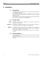
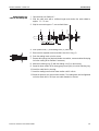
2.5
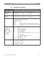
Connections
1
2.6
2.6.1
Scales interfaces
Serial interfaces
Network and field bus
connections
Further interfaces
10
2 3
4
1
Mains connection
2
COM1 – standard RS232 interface
3
Equipotential bonding terminal (only IND690xx)
4
Optional interface connections COM2 ... COM9
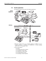
Interfaces
Overview
By default the IND690(xx) has an RS232 interface (COM1). A maximum total of
8 further interfaces can be installed (COM2 ... COM9).
The following further interfaces are available:
Designation
Note
Design
IDNet-690
For connecting IDNet weighing platforms
SICS-Scale-690
For connecting SICS weighing platforms
Push-on
modules
AnalogScale-690
For connecting analog weighing platforms
Interface card
CL20mA-690
–
RS232-690
–
RS485/422-690
Can be configured as RS485 or RS422
USB-690
–
Ethernet-690
–
ProfibusDP-690
–
WLAN-690
–
Bluetooth-690
–
4I/O-690
Digital inputs/outputs
AnalogOut-690
Digital-analog output
PS2-690
For connecting an external keyboard
AlibiMemory-690
Alibi memory
Push-on
modules
Network cards
Push-on
modules
Internal card
Installation information 22012803E 09/08
IND690 / IND690xx / IND690-24V
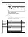
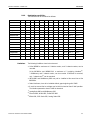
2.6.2
Introduction
Combination possibilities
The interfaces can be combined as follows:
COM1 COM2 COM3 COM4 COM5 COM6 COM7 COM8 COM9 IND690 IND690xx IND690-24V
RS232-690
x
x
x
x
x
x
x
x
x
max. 9
max. 9
max. 9
IDNet-690
–
x
x
x
x
–
–
–
–
max. 4
max. 3
max. 3
SICS-Scale-690
–
x
x
x
x
–
–
–
–
max. 4
max. 3
max. 3
AnalogScale-690
–
x
x
x
x
–
–
–
–
max. 4
max. 3
max. 3
CL20mA-690
–
x
x
x
x
x
x
x
x
max. 8
max. 8
max. 8
RS485/422-690
–
x
x
x
x
x
x
x
x
max. 8
max. 8
max. 8
USB-690
–
x
x
x
x
x
x
x
x
max. 1
max. 1
max. 1
Ethernet-690
–
x
x
x
x
x
x
x
x
max. 1
max. 1
max. 1
ProfibusDP-690
–
x
x
x
x
x
x
x
x
max. 1
max. 1
max. 1
WLAN-690
–
x
x
x
x
x
x
x
x
max. 1
max. 1
max. 1
Bluetooth-690
–
x
x
x
x
x
x
x
x
max. 4
max. 2
max. 2
4I/O-690
–
–
–
–
x
x
–
–
–
max. 2
max. 2
max. 2
AnalogOut-690
–
–
–
–
x
x
–
–
–
max. 2
max. 2
max. 2
PS2-690
–
–
–
–
–
–
–
–
x
max. 1
max. 1
max. 1
AlibiMemory-690
–
x
x
x
x
x
x
x
x
max. 1
max. 1
max. 1
Limitations
The following limitations have to be observed:
• At the IND690 a maximum of 4 interface cards1) and 2 networks cards2) can be
mounted.
At the IND690xx and IND690-24V a maximum of 3 weighing interfaces3),
1 AlibiMemory and 2 network cards2) can be mounted. If Bluetooth is mounted,
only 1 network card2) can be mounted.
• WLAN-690 and AlibiMemory-690 may not be installed at the same time at the
IND690xx.
• Scale interfaces3) have to be installed without gaps beginning with COM2.
• It must be ensured that no voltages are fed into the terminal than it itself provides.
The interface parameters have to fulfill the standard.
1)
AnalogScale-690 and AlibiMemory-690
2)
Ethernet-690, WLAN-690, ProfibusDP-690
3)
IDNet-690, SICS-Scale-690, Analog Scale-690
Installation information 22012803E 09/08
11
IND690 / IND690xx / IND690-24V
Introduction
• The following total load of the output voltages is to be observed when several
peripheral devices are connected:
Output voltage 5 V
IND690
max. 600 mA
Output voltage 12 V
Output voltage 24 V
max. 200 mA
max. 100 mA
IND690xx / IND690-24V
max. 100 mA to max. 300 mA,
depending on the design level *
max. 200 mA
max. 100 mA
* At the IND690xx and IND690-24V the maximum total load of the 5 V output
voltage depends on the combination of the installed interface modules and
network cards. If a combination of the interface modules or the network cards
Ethernet-690, WLAN-690, Profibus-DP-690 and Bluetooth-690 is used, the 5 V
output voltage may have a maximum load of 100 mA.
EXPLOSION HAZARD
➜ When connecting several external devices to the power-limited 5 V output voltage
of the IND690xx, observe the following total connection values for the total of all
devices including cables:
Total capacity parallel on 5 V
Total inductance in series on 5 V
12
Co = max. 200 μF
Lo = max. 60 μH
Installation information 22012803E 09/08
IND690 / IND690xx / IND690-24V
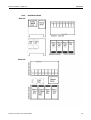
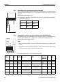
2.6.3
Introduction
Installation scheme
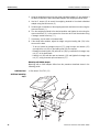
Desk unit
Panel unit
Installation information 22012803E 09/08
13
IND690 / IND690xx / IND690-24V
Commissioning
3
Commissioning
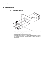
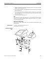
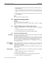
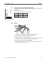
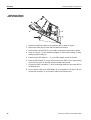
3.1
Mounting the panel unit
1
3
2
4
3
1. Affix the supplied drilling template to the control cabinet and saw out the cut-out
for the cover exactly using the sabre saw.
2. Insert the housing (1) from the front into the cut-out.
3. Place on the securing clamps (3) on the rear and fasten them with 6 hexagon
nuts (4) and 6 washers (2). Place the washers so that the cover can be
removed easily.
14
Installation information 22012803E 09/08
IND690 / IND690xx / IND690-24V
3.2
3.2.1
Commissioning
Mounting the desk unit
Mounting with brackets and stands
METTLER TOLEDO offers the following options for mounting brackets and stands:
Description
9
1
3
8
8
2
11
21
1
5
6
7
Installation information 22012803E 09/08
IND690 wall bracket
For mounting the IND690 weighing
terminal on the wall, complete with
mounting screws, stainless
22 011 980
IND690 floor stand
For fixed mounting the IND690
weighing terminal to the floor,
complete with mounting material,
height 1000 mm, stainless
22 011 981
IND690 bench stand
For mounting the weighing terminal to
the weighing bench for KB, MB, KCC,
MCC and PBA430 weighing platforms,
height 500 mm, stainless
22 011 986
IND690 stand articulated adapter
Retrofit set for old stands, with the
exception of scale stand 00 504 439,
stainless
22 011 984
Stand base
For movable installation of the floor
stand, stainless
22 011 982
GA46 adapter
For mounting the GA46 printer in
combination with the IND690 to the
floor stand or to the wall bracket,
stainless
May not be mounted to IND690xx!
22 011 985
15
IND690 / IND690xx / IND690-24V
Commissioning
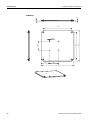
3.2.2
Dimensional drawings
125
100
30
18
Ø9
32
Wall bracket
244
60
120
142
45
180
± 90°
183
-15°
+45°
GA46 adapter
26
Ø9
40
45°
350
(54)
(65)
Ø9
26
80
(100)
16
Installation information 22012803E 09/08
IND690 / IND690xx / IND690-24V
Commissioning
Floor stand
(6)
40
135
160
Ø9
60
~ 1036
135
160
180°
18
32
45°
~ 60
74
(180)
16
Ø8
30
Installation information 22012803E 09/08
17
IND690 / IND690xx / IND690-24V
Commissioning
20 +10
15
Stand base
420
119.5
478
420
135
Ø9 (4x)
135
478
18
Installation information 22012803E 09/08
IND690 / IND690xx / IND690-24V
3.2.3
Commissioning
Safety instructions
▲ The supplied mounting material and the instructions are determined for fastening
to concrete or stone masonry and stone or concrete floors. Ensure that the
dowels are located in fixed masonry or fixed flooring.
▲ Before drilling any holes ensure that there are no electrical line or pipes in the
wall or in the floor.
▲ IND690 and GA46 can only be disconnected from the power supply by pulling
the power plug. The socket-outlet has to be freely accessible.
▲ The GA46 adapter may not be mounted at the IND690xx, since the GA46 printer
and GA46 adapter are not approved for use in a hazardous area.
▲ IND690xx does not have a power plug. The power connection has to be
connected to a suitable connection socket that is freely accessible. The terminal
can only be disconnected from the power supply by means of a suitable external
disconnecting device.
▲ The distance from the weighing terminal and GA46 to the socket outlet or to the
connection socket may not exceed 2.20 m in case of wall mounting. In case of
floor mounting the distance from the cable outlet at the floor stand to the socket
outlet or connection socket may not exceed 1.20 m.
▲ The power cord must be laid directly and freely to the socket outlet. It may not be
laid through holes and openings. It may not be laid in cable ducts or fastened to
the wall or other objects using cable clamps or other fastening material.
▲ In addition observe the respective national standards and safety regulations.
▲ During assembly and disassembly various parts of the wall bracket and at the
floor stand can be moved. Be careful not to pinch fingers or cables.
▲ All the screws have to be tightened.
▲ If the stand articulated adapter is screwed tight so that the terminal can be rotated
and tilted, it is possible that cables, fingers or other parts can be jammed or
pinched.
▲ Ensure during assembly and disassembly in particular that the floor stand does
not tilt and that the terminal or other parts do not fall down. Risk of injury.
▲ Mount the floor stand, also in connection with the stand base vertically.
Otherwise there is a danger of tilting. The stand base may not wobble. If
necessary, adjust it using the leveling feet.
Installation information 22012803E 09/08
19
IND690 / IND690xx / IND690-24V
Commissioning
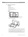
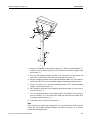
3.2.4
Mounting the desk unit to the wall
Required tools
• Hand drill
• Stone drill bit ∅ 8 mm
• Open end wrench size 10 mm (1)
• Box wrench size 5.5 mm (2)
• 2 x open end wrench size 13 mm (3)
Mounting
Approximate required space
120
250
100
75
Dimensions in mm
500
1. Drill holes in the wall in accordance with the drawing (not to scale):
4 holes, ∅ 8 mm, 60 mm deep.
9
1
1
3
8
10
8
7
6
5 4
2
2. Screw the completely premounted wall bracket (4) with the supplied dowels (7),
washers (6) and wooden screws (5) to the wall using the open end wrench (1).
3. Turn over the weighing terminal, place it on its front side on a soft surface and
loosen the 2 screws (8) on the cover rear using the box wrench (2).
4. Hang the weighing terminal into the stand articulated adapter (9) and position it
so that the holes of the stand articulated adapter and weighing terminal match.
20
Installation information 22012803E 09/08
IND690 / IND690xx / IND690-24V
Commissioning
5. Use the 2 screws (8) to mount the weighing terminal to the stand articulated
adapter using the box wrench (2).
6. Set the angle of inclination of the weighing terminal and fasten the nuts using the
open end wrench (1).
7. Turn the weighing terminal to the desired position and tighten the nuts using the
open end wrench (3). In the process the screw has to be held with a second
open end wrench (3).
8. Close the tube with tube plugs (10).
Note
When carrying out repairs and maintenance it is only necessary to loosen the two
screws (8) at the stand articulated adapter using the box wrench (2) in order to
remove the weighing terminal.
Mounting with GA46 adapter
Mounting with a GA46 adapter differs from the procedure described above in the
following points:
Additional tool
• Hexagon socket screw key size 6 mm (11)
• Box wrench Torx T20 (12)
Additional mounting
steps
19
13
8
18
17
3
8
14
2
1
15
16
20
12
11
Installation information 22012803E 09/08
21
IND690 / IND690xx / IND690-24V
Commissioning
1. Before beginning the mounting work dismantle the stand articulated adapter (13)
and wall bracket (14) using the open end wrench (3).
2. Fasten the GA46 adapter (15) with the long screw (16), the spring washer (17)
and the nut (18) to the wall bracket and stand articulated adapter using the
hexagon socket screw key (11).
3. Before hanging in the terminal, fasten the GA46 printer (19) with 3 screws (20)
to the GA46 adapter using the box wrench (12).
Note
The printer GA46 can be turned as required.
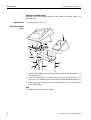
3.2.5
Mounting the desk unit fixed to the floor
Required tools
• Hand drill
• Stone drill bit ∅ 8 mm
• Open end wrench size 10 mm (1)
• Box wrench size 5.5 mm (2)
• Open end wrench size 13 mm (3)
• Hexagon socket screw key size 6 mm (11)
Mounting
Approximate required space: 200 x 200 mm
135
135
Dimensions in mm
1. Drill holes in the floor in accordance with the drawing (not to scale):
4 holes, ∅ 8 mm, 60 mm deep.
22
Installation information 22012803E 09/08
IND690 / IND690xx / IND690-24V
Commissioning
9
1
3
8
8
2
11
21
1
5
6
7
2. Screw the completely premounted floor stand (21) with the supplied dowels (7),
washers (6) and wooden screws (5) at all 4 holes onto the floor using the open
end wrench (1).
3. Turn over the weighing terminal, place it on its front side on a soft surface and
loosen the 2 screws (8) on the cover rear using the box wrench (2).
4. Hang the weighing terminal into the stand articulated adapter (9) and position it
so that the holes of the stand articulated adapter and weighing terminal match.
5. Use the 2 screws (8) to mount the weighing terminal to the stand articulated
adapter using the box wrench (2).
6. Set the angle of inclination of the weighing terminal and fasten the nuts using an
open end wrench (1).
7. Turn the weighing terminal to the desired position and tighten the nuts using an
open end wrench (3). In the process the screw has to be held from below using
a hexagon socket screw key (11).
8. If necessary, lay the cable in the stand tube.
Note
When carrying out repairs and maintenance it is only necessary to loosen the two
screws (8) at the stand articulated adapter using the box wrench (2) in order to
remove the weighing terminal.
Installation information 22012803E 09/08
23
IND690 / IND690xx / IND690-24V
Commissioning
Mounting with GA46 adapter
Mounting with a GA46 adapter differs from the procedure described above in the
following points:
Additional tool
• Box wrench Torx T20 (12)
Additional mounting
steps
19
13
17
18
3
1
8
8
2
15
16
20
21
12
11
1. Before beginning the mounting work dismantle the stand articulated adapter (13)
and floor stand (21).
2. Fasten the GA46 adapter (15) with the long screw (16), the spring washer (17)
and the nut (18) between the floor stand and the stand articulated adapter (13).
3. Before hanging in the terminal, fasten the GA46 printer (19) with 3 screws (20)
to the GA46 adapter.
Note
The GA46 printer can be turned as required.
24
Installation information 22012803E 09/08
IND690 / IND690xx / IND690-24V
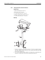
3.2.6
Commissioning
Setting up with floor stand and stand base
Required tools
• Open end wrench size 10 mm (1)
• Box wrench size 5.5 mm (2)
• 2 x open end wrench size 13 mm (3)
• Hexagon socket screw key size 6 mm (11)
• 2 x open end wrench size 17 mm (22)
Mounting
9
1
3
8
8
2
11
21
3
27
5
22
28
29
6
26
3
1. Screw the completely premounted floor stand (12) with the supplied hexagon
nuts (26), washers (6) and screws (5) at all 4 holes to the stand base using
two open end wrenches (3).
2. Turn over the weighing terminal, place it on its front side on a soft surface and
loosen the 2 screws (8) on the cover rear using the box wrench (2).
Installation information 22012803E 09/08
25
IND690 / IND690xx / IND690-24V
Commissioning
3. Hang the weighing terminal into the stand articulated adapter (9) and position it
so that the holes of the stand articulated adapter and weighing terminal match.
4. Use the 2 screws (8) to mount the weighing terminal to the stand articulated
adapter using the box wrench (2).
5. Set the angle of inclination of the weighing terminal and fasten the nuts using the
open end wrench (1).
6. Turn the weighing terminal to the desired position and tighten the nuts using the
open end wrench (3). In the process the screw has to be held from below using
a hexagon socket screw key (11).
7. If necessary, lay the cable in the stand tube.
8. If the stand base wobbles, adjust the height using the leveling feet (29) in the
corners of the base.
– To do so, loosen the hexagon cap nut (27) using the open end wrench (22)
and adjust the nut (28) on the leveling foot (29) as required.
– Refasten the leveling foot (29) with set nut (28) by hand with the hexagon cap
nut (27) in the stand base.
– Hold the nut (28) with the open end wrench (22) and tighten the hexagon cap
nut (27) using a second open end wrench (27).
Mounting with GA46 adapter
Mounting with a GA46 adapter differs from the procedure described above in the
following points:
Additional tool
• Box wrench Torx T20 (12)
Additional mounting
steps
19
13
17
18
3
1
8
8
2
15
16
20
21
12
11
26
Installation information 22012803E 09/08
IND690 / IND690xx / IND690-24V
Commissioning
1. Before beginning the mounting work dismantle the stand articulated adapter (13)
and floor stand (21).
2. Fasten the GA46 adapter (15) with the long screw (16), the spring washer (17)
and the nut (18) between the floor stand (21) and the stand articulated adapter
(13).
3. Before hanging in the terminal, fasten the GA46 printer (19) with 3 screws (20)
to the GA46 adapter.
Note
The GA46 printer can be turned as required.
3.3
Connecting the weighing platform
Condition
A corresponding scales interface is installed.
If this is not yet the case, see Section 4.2 (IDNet, SICS) or Section 4.3 (Analog
Scale).
3.3.1
Connecting weighing platforms with an IDNet or SICS connection
1. Set up the weighing platform, see the installation instructions of the weighing
platform.
2. Lay the weighing platform cable to the weighing terminal.
3. Connect the weighing platform connector to the weighing terminal.
3.3.2
Connecting analog weighing platforms
CE conformity
With longer connection cables, shielding measures against radiation and irradiation
of interference are particularly important.
The required interference immunity classes will only be achieved with careful
installation and wiring of all connected peripherals, weighing platforms and weighing
cells. For this purpose the shielding must be connected properly on both ends.
The CE conformity of the entire system is the responsibility of the person
commissioning the device.
Verified weighing
platforms
Verified weighing platforms require the ID card which has to be mounted via the
weighing terminal cable before connection to the weighing terminal. In addition the
analog PCB has to be sealed.
Please contact the METTLER TOLEDO Service for labelling and verification of your
weighing system.
Preparatory work
1. Set up the weighing platform, see the installation instructions of the weighing
platform.
2. Lay the weighing platform cable to the weighing terminal.
3. Open terminal, see Section 4.1.
4. Remove the heavy-gauge screw joint for the weighing terminal connection.
5. Pull the test cable off the AnalogScale-690 PCB.
Installation information 22012803E 09/08
27
IND690 / IND690xx / IND690-24V
Commissioning
Preparing the weighing
platform cable
1. Strip the cable ends with a sufficient length and shorten the cable shield to 6 mm.
2. Strip the core ends approx. 7 mm and twist them.
3. Push on the wire end ferrules and press them on firmly with a pair of crimping
pliers. The cable ends may not project over the wire end ferrules.
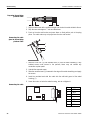
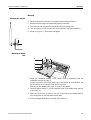
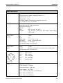
Connecting the cable
gland to the weighing
platform cable
1
2
3
1. Slide the union nut (3) and moulded seal (2) over the cable sheathing. If any
braided screen cores loosen in the process, these may not contact any
conductive system parts!
2. Unbraid the exposed screen.
3. Slide the moulded seal (2) forwards to the edge of the cable sheathing and apply
the screen.
4. Insert the moulded seal with the cable into the anti-twist guard of the metal
housing (1).
5. Screw the union nut onto the metal housing, but do not tighten it.
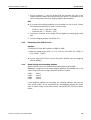
Connecting the cable
28
Pin
Assignment
1
+ EXC
2
+ SEN
3
+ SIG
4
–
5
– SIG
6
– SEN
7
– EXC
Installation information 22012803E 09/08
IND690 / IND690xx / IND690-24V
Commissioning
1. Pull the connector (1) from the analog PCB and terminate the cores of the
weighing platform cable at the connector as shown above. For information on the
colour coding please refer to the weighing platform documentation.
Note
➜ If the cable of the weighing platform to be connected has only 4 cores, connect
the following terminal pairs by means of a wire jumper.
– Terminal 1 and 2 (+ EXC and + SEN)
– Terminal 6 and 7 (– SEN and – ECX)
2. Connect the connector at the analog PCB and tighten the heavy-gauge screw
joint.
3. Close the weighing terminal, see Section 4.9.
3.3.3
Connecting LabTec X/XP/XS scales
Condition
• Interface SICS-Scale-690 installed on COM2 to COM5
• Switch the voltage supply from 5 V to 12 V via pin, see Section 3.4 (COM1) or
4.2.2 (COM2 ... COM5)
➜ Use the cable 22015128 to connect the LabTec X/XP/XS scale and weighing
terminal IND690.
3.3.4
Commissioning several weighing platforms
Scales interfaces have to be installed without gaps beginning with COM2.
IND690(xx) recognizes the connected weighing platforms automatically and, in the
case of brand new scales, assigns the scales number as follows:
COM2
COM3
COM4
COM5
Scale 1
Scale 2
Scale 3
Scale 4
If used weighing platforms are connected, two weighing platforms may have the
same scales number. In this case IND690(xx) automatically activates the service
mode in order to assign a new scales number. Call the METTLER TOLEDO Customer
Service.
Installation information 22012803E 09/08
29
IND690 / IND690xx / IND690-24V
Commissioning
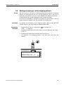
3.4
Pin 5 of the standard RS232-interface COM1 can be configured for connecting
devices requiring a supply voltage of 12 V. The maximum current load may not
exceed 100 mA.
Default setting at the factory: +5 V
-
+
Configuring COM1
1. Open terminal, see Section 4.1.
2. Configure the soldering jumpers BR1 and BR2 on the main PCB:
3.5
Pin 5
BR1
BR2
+5 V
open
closed
+12 V
closed
open
Connecting the ProfibusDP-690
EXPLOSION HAZARD
Observe the following points when installing the ProfibusDP-690 field bus card into
the IND690xx:
➜ Only use special bus cables with shielding and with a diameter ≥ 7 mm.
Recommended wire cross-section ≥ 0.34 mm2.
➜ Tighten the cable glands so that a strain relief of ≥ 20 N per mm cable crosssection is attained.
CE conformity
With longer connection cables, shielding measures against radiation and irradiation
of interference are particularly important.
The required interference immunity classes will only be achieved with careful
installation and wiring of all connected peripherals, weighing platforms and weighing
cells. For this purpose the shielding must be connected properly on both ends.
The CE conformity of the entire system is the responsibility of the person
commissioning the device.
Cable specifications
Only use special bus cables with shielding and with a diameter ≥ 7 mm!
Recommended wire cross-section ≥ 0.34 mm2.
30
Installation information 22012803E 09/08
IND690 / IND690xx / IND690-24V
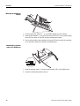
Connecting the bus
cable to the cable gland
Commissioning
1. Open terminal, see Section 4.1.
2. Strip the cable ends with a sufficient length and shorten the cable shield to
approx. 12 – 13 mm.
3. Strip the core ends approx. 7 mm and twist them.
4. Push pressure nut (1) and sealing insert (2) onto cable.
5. Bend over the exposed screen and slide it over the O-ring (3).
6. Push the sealing insert up to the screen.
7. Remove blind plugs from desired interface connection; remove another blind plug
for further routing of the Profibus if necessary.
8. Mount the reducing ring (5) with the sealing nut (6) on the housing.
9. Screw the lower section of the heavy-gauge screw joint (4) into the reducing ring.
10. Insert the cable into the housing.
11. Insert the sealing insert into the lower section until it is flush.
12. Screw the pressure nut onto the lower section. The cable gland must be tightened
so that a strain relief ≥ 20 N per mm cable diameter is ensured.
Installation information 22012803E 09/08
31
IND690 / IND690xx / IND690-24V
Commissioning
Terminating the bus
cable
➜ Pull the Mini-Combicon terminal strip (a) off the Profibus card and connect the
bus cable to the terminal strip in accordance with the following table:
Terminal
Assignment
Note
1
Repeater controller RTS
5-V request-to-send (RTS) signal
2
Data Ground
Reference potential for RS485 level
3
Output data signal B
Positive RS485 signal level,
to next node, colour red
4
+5 V, insulated
5-V supply, e.g. for fibre-optics adapter
5
Output data signal A
Negative RS485 signal level,
to next node, colour green
6
–
–
7
–
–
8
Input data signal B
Positive RS485 signal level,
from last node, colour red
9
Repeater controller RTS
5-V request-to-send (RTS) signal
10
+5 V, insulated
5-V supply, e.g. for fibre-optics adapter
11
Data Ground
Reference potential for RS485 level
12
Input data signal A
Negative RS485 signal level,
from last node, colour green
Setting matching
resistor
➜ If necessary, activate the matching resistor directly on the ProfibusDP-690
interface. To do this, set all dip switches to ON.
Diagnostic LEDs
The 4 diagnostic LEDs on the ProfibusDP-690 interface output the following states:
Yellow LED
Green LED
Red LED
Green LED
32
Operating voltage switched on
Profibus data cycles started
Communication dialog faulty
Sign of activity in secondary cycle
Installation information 22012803E 09/08
IND690 / IND690xx / IND690-24V
3.6
Commissioning
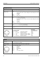
Marking and sealing on verified weighing platforms
ID code
With the ID code you can check on verified weighing platforms whether the weighing
platform has been tampered with since the last verification. The ID code can be
displayed on the terminal at any time, see the IND690-Base operating instructions.
During verification the currently displayed ID code is saved and sealed.
Each time the configuration is changed, the displayed ID code increases. It then no
longer matches the sealed ID code; the verification is no longer valid.
Verification
For marking and verification of your weighing system, please contact METTLER
TOLEDO Service or your local Weights and Measurements Office.
Checking the
verification
1. Displaying the ID code: to do so keep the
key pressed until
CODE = ... is displayed.
On weighing platforms that cannot be verified, no value is displayed, but instead:
CODE ===.
2. Compare the ID code with the sealed ID code on the ID card.
The verification of the weighing system is only valid when both values are
identical.
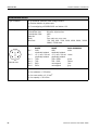
1 2 3
9 20 1 2 3 4 5
TCODE
1
Type:
KB60.2
S/N 2088678
D93-09-108
Max 15/30/60kg
Min 0,1kg
e=5/10/20g
1 Max 6kg
d=1g
IDENTCODE W1 = 2
Installation information 22012803E 09/08
33
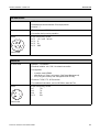
IND690 / IND690xx / IND690-24V
Commissioning
CODE
Mettler-Toledo GmbH
D-72458 Albstadt/Made in Germany
Verkauf und Kundendienst
Mettler-Toledo GmbH
D-35396 Giessen
Tel.0641-5070 / Fax. 0641/500000
Type: ID7
S/N 12345678
100V ... 240V 50/60Hz
480mA ... 240mA
IDENTCODE 2
Type:
2
Max
kg
Min
kg
e=
kg
CE
1
IDENTCODE W1 = 2
3. Press the
key again.
The connected weighing platform is checked. The display shows CHECKING
WEIGHING PLATFORM and then WEIGHING PLATFORM IS OK after the test is
completed.
Then the IND690(xx) returns automatically to normal mode.
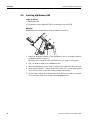
3.7
3.7.1
Particular points when commissioning the IND690xx
Equipotential bonding
The equipotential bonding must be installed by a professional electrician when using
the IND690xx weighing terminal in hazardous areas.
➜ Connect equipotential bonding of all devices in accordance with the countryspecific regulations and standards. In the process, ensure that all device
housings are connected to the same potential via the PA terminals.
Equipotential bonding terminal IND690xx
The equipotential bonding terminal of the IND690xx is found on the COM1 socket.
Equipotential bonding terminal weighing platforms
The equipotential bonding terminal and mounting materials are enclosed with the
IND690xx weighing terminal.
3.7.2
Testing restricted breathing at weighing platforms with restricted breathing
A restricted breathing test according to the relevant country-specific standards is
required in the following cases:
• before first-time commissioning
• at regular intervals thereafter
• after accidental cleaning of the diaphragm with steam jets
A test protocol must be created after each test.
34
Installation information 22012803E 09/08
IND690 / IND690xx / IND690-24V
3.7.3
Commissioning
Limited mobility at IND690xx
EXPLOSION HAZARD
The IND690xx weighing terminal, accompanying weighing platforms and
accessories may only be operated in Zone 2 and 22 hazardous areas.
Cabling
➜ Protect data and signal cable extensions against inadvertent disconnection by
sealing.
➜ Always secure interface connections on the rear using a bracket.
3.7.4
Labelling for operation in hazardous area
The following signs must be mounted on the IND690xx weighing terminal,
accompanying weighing platforms and accessories so that they are clearly visible:
• Model plate with the device’s model data, manufacturer and serial number
• Safety instructions
• Zone marking
• Temperature range
• For measuring cells with restricted breathing: provide test plate with the date,
underline it, and stick it to measuring cell.
Installation information 22012803E 09/08
35
IND690 / IND690xx / IND690-24V
Commissioning
3.8
3.8.1
Mains connection / connecting 24 V power supply
Connecting the IND690 to the mains
CAUTION
The IND690 weighing terminal only operates properly with a mains voltage of 100 V
to 240 V.
➜ Ensure that the supply voltage at the installation site lies within this range.
➜ Ensure that the mains outlet is earthed and easily accessible.
Connecting
➜ Plug the mains plug into a mains outlet.
In the factory setting the display briefly shows the version of the installed
software, the text METTLER TOLEDO IND690 and all the connected scales; then
the weight display appears.
3.8.2
Connecting the IND690xx to the mains
EXPLOSION HAZARD
➜ The mains connection may only be connected by the owner’s electrician.
CAUTION
The IND690xx weighing terminal only operates properly with a mains voltage of
100 V to 240 V.
➜ Ensure that the supply voltage at the installation site lies within this range.
➜ Ensure that the mains outlet is earthed.
➜ Ensure that equipotential bonding has been implemented.
3.8.3
Connecting the IND690-24V to the power supply
CAUTION
The IND690-24V weighing terminal only functions correctly with a 24 VDC power
supply.
➜ Ensure that the IND690-24V is only connected to a power supply (storage battery
or mains) having a 24 VDC SELV power circuit in accordance with EN 60950.
36
Installation information 22012803E 09/08
IND690 / IND690xx / IND690-24V
Commissioning
Selecting storage battery or mains operation
The IND690-24V weighing terminal is set to storage battery operation at the factory.
1. Open weighing terminal, see Section 4.1.
2. Remove power supply unit cover.
1
3. Set the switch (1) to the desired position:
left
right
storage battery operation (default setting)
mains operation
4. Replace power supply unit cover and close IND690-24V weighing terminal.
Earthing
The blue lead of the power cable is connected to the GND of the individual voltages
and the housing internally.
➜ This is why we recommend the earthing of GND or the negative pole of the supply
voltage.
Mains operation
➜ We recommend that the green-yellow lead of the power cable be connected to the
earth or the equipotential bonding of the mains or the system.
Storage battery
operation
➜ If the negative pole of the storage battery is not earthed, the green-yellow lead of
the power cable need not be connected.
➜ If the negative pole of the storage battery is earthed, we recommend that the
green-yellow lead of the power cable be connected to the equipotential bonding.
Connecting
➜ Connect the leads of the power cable as follows:
brown lead
+24 V
blue lead
0 V or negative pole
Plug mains plug of IND690-24V into a mains outlet.
In the factory setting the display briefly shows METTLER TOLEDO IND690 and the
versions of the installed components; then the weight display appears.
Installation information 22012803E 09/08
37
IND690 / IND690xx / IND690-24V
Retrofitting
4
Retrofitting
4.1
Opening terminal
EXPLOSION HAZARD
➜ Do not open the IND690xx in an explosive dust atmosphere.
➜ On the IND690xx, wait 5 minutes after disconnection from the mains before
opening the device or removing the plug.
CAUTION
Before opening the device:
1. Switch off weighing terminal.
2. Disconnect the terminal from the power supply:
– at the IND690xx deenergize the mains connection or power supply,
– at the IND690-24V deenergize the power supply or pull the power plug,
– at the IND690 pull the power plug.
Opening the desk unit
1. Turn the device around carefully and unscrew the 12 screws on the cover
underside.
2. Return the device to its normal position and lay the cover down forwards.
3. Disconnect the display and keyboard cables.
4. In order to access the components on the main PCB underside or at the housing
base swivel the main PCB upwards.
Opening the panel unit
1. Remove the 2 nuts.
2. Remove the cover.
3. Disconnect the display, keyboard and power cables.
4. In order to access the components on the main PCB underside or at the socket
carrier plate swivel the main PCB downwards.
Note
At the IND690xx the interface connectors on the rear are secured with a clamp. If
applicable, remove the clamps.
38
Installation information 22012803E 09/08
IND690 / IND690xx / IND690-24V
4.2
Retrofitting
Mounting push-on modules
Mounting of the following interfaces is identical:
• IDNet-690
• SICS-Scale-690
• CL20mA-690
• RS232-690
• RS485/422-690
• USB-690
• 4I/O-690
• AnalogOut-690
• PS2-690
At the modules CL20mA-690, RS232-690 and RS485/422-690 preparatory work
(switch settings, soldering jumpers) may be necessary.
4.2.1
Setting the operating mode at the interface module CL20mA-690
The CL20mA-690 interface module can be operated with either an active or a
passive transmission and reception loop.
Factory setting: Passive transmission and reception loop
➜ Set the desired operating mode with the switch SW1 to SW6 on the underside of
the CL20mA-690.
SW2
SW5
SW6
closed
closed
closed
open
open
SW1
SW3
SW4
Reception loop active
open
closed
closed
Reception loop passive
closed
open
open
Transmission loop active open
ON
SA1
1
6
Transmission loop
passive
Installation information 22012803E 09/08
39
IND690 / IND690xx / IND690-24V
Retrofitting
4.2.2
Configuring Pin 5 at the interface module RS232-690
Pin 5 of the RS232-690 interface module can be configured for connecting devices
requiring a supply voltage of 12 V. The maximum current load may not exceed
100 mA.
Default setting at the factory: +5 V
BR2 BR3
➜ Configure the soldering jumpers BR2 and BR3 on the underside of the RS232690 interface module.
4.2.3
Pin 5
BR2
BR3
+5 V
closed
open
+12 V
open
closed
Configuring the interface type at the interface module RS485/422-690
The operating mode of the RS485/422-690 interface module is determined by the
position of the switches SW1 – SW6 on the underside of the interface module.
Default setting at the factory: RS485
Notes
• When a matching resistor is used the overall load impedance may not drop below
100 Ω.
SA2
• At RS485 the resistors activated with SW3 – SW5 ensure that levels defined at the
receiver are applied when no station drives the cable.
ON
1
6
➜ Set the switches SW1 – SW6 on the interface PCB.
RS422 ON
SW1
OFF
x
RS485 ON
SW1
SW2
x
SW2
SW3
x
SW3
SW4
x
SW5
x
SW6
40
x
RS485 /
relay box ON
/ ARM100
OFF
x
OFF
SW1
SW2
x
Pull-up resistor for TxD+/ Pull-up resistor for TxD+/
RXD+ active
RXD+ not active
SW3
x
SW4
Matching resistor 150 Ω
active
Matching resistor 150 Ω
not active
SW4
SW5
Pull-down resistor for
TxD–/RXD– active
Pull-down resistor for
TxD–/RXD– not active
SW5
x
SW6
SW6
x
x
x
x
x
Installation information 22012803E 09/08
IND690 / IND690xx / IND690-24V
4.2.4
Retrofitting
Switching power supply at the 4I/O-690 interface module
The relay box 4-690 is supplied with power either internally by the weighing terminal
or externally.
Factory setting: Internally
➜ Set switches SW1 and SW2 on the interface print.
O
N
SW1
SW2
Internally
ON
ON
Externally
OFF
OFF
1 2
4.2.5
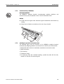
Mounting
1. Select the interface connection in accordance with the table on Page 11.
2. Remove the blind plug from the desired interface connection.
3. Unscrew the ring nut (1) from the socket PCB.
4. Route the socket (2) from the inside of the housing through the hole to the
outside. Ensure proper seating of rubber sealing ring when doing so.
5. Screw on the ring nut from the outside and tighten it.
6. Push the interface module (3) onto the main PCB. When doing so, ensure that
the arrow points towards the socket.
Installation information 22012803E 09/08
41
IND690 / IND690xx / IND690-24V
Retrofitting
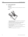
4.3
Installing AnalogScale-690
Scope of delivery
• Analog PCB
• PCB adapter for connecting to the main PCB with analog cable for connecting to
the analog PCB
Mounting
2
3
4
1
1. Select the installation position of the analog PCB (Point) in accordance with the
installation scheme on Page 13.
Mounting on the underside of the main PCB (Slot 3) is shown in the graphic.
2. Select the interface connection in accordance with the table on Page 11.
3. Remove the blind plug from the desired interface connection.
4. Mount the analog PCB (3) using the nut (4) on the premounted bolts on the
underside of the main PCB.
5. Plug the PCB adapter (1) into a free slot on the top of the main PCB.
6. Lay the analog cable (2) to the underside of the main PCB and connect to the
analog PCB.
7. Connect the analog weighing platform, see Section 3.3.2.
42
Installation information 22012803E 09/08
IND690 / IND690xx / IND690-24V
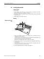
4.4
Retrofitting
Installing Ethernet-690
Scope of delivery
• Ethernet card
• Socket adapter: socket PCB with connecting cable for connecting to the RJ45
socket of the Ethernet card, in addition 1 ring nut
• PCB adapter: PCB for connecting to the main PCB with ribbon cable for connecting
to the Ethernet card
• Adapter plate for mounting in desk unit
Mounting
Mounting the Ethernet
card
.
3
2
1
1. Select the installation position of the Ethernet card in accordance with the
installation scheme on Page 13.
If within the panel unit the WLAN card is to be mounted at the same position, the
Ethernet card has to be mounted on the WLAN card.
Mounting on the adapter plate (right) is shown in the graphic.
2. Place the spacer sleeves (1) on the respective holes in the adapter sheet and turn
in the studs (2).
3. Mount the Ethernet card (3) using 3 nuts on the bolts on the adapter plate at the
housing base or onto the socket carrier plate.
4. Insert the adapter plate into the housing until it latches in.
Installation information 22012803E 09/08
43
Retrofitting
IND690 / IND690xx / IND690-24V
Mounting the Ethernet
socket and PCB adapter
1. Select the interface connection in accordance with the table on Page 11.
2. Remove the blind plug from the desired interface connection.
3. Guide socket of socket PCB (5) from inside of housing through hole to outside.
4. Screw on ring nut (3) from outside and tighten. Ensure proper seating of rubber
sealing ring when doing so.
5. Ensure that the DIP switches 1 – 4 on the PBC adapter are set for Ethernet.
6. Insert the PCB adapter (4) into a free slot of the main PCB. Ensure proper poling
of the PCB: the arrow on the PCB must point toward the sockets.
7. Connect the RJ45 connection (1) of the connecting cable from the socket PCB to
the Ethernet card.
8. Lay the ribbon cable of the PCB adapter to the underside of the main PCB and
connect the connector (2) of the ribbon cable to the Ethernet card.
44
Installation information 22012803E 09/08
IND690 / IND690xx / IND690-24V
4.5
Retrofitting
Installing the ProfibusDP-690
Scope of delivery
• Profibus card with connected Mini-Combicon terminal strip
• PCB adapter: ribbon cable with PCB for connecting to the main PCB
• 2 screw cable fittings (M 16 x 1.5) with blind plugs
• Adapter plate for mounting in desk unit
Mounting
Mounting the Profibus
card
.
3
2
1
1. Select the installation position of the Profibus card in accordance with the
installation scheme on Page 13.
2. Place the spacer sleeves (1) on the respective holes in the adapter sheet and turn
in the studs (2).
3. Mount the Profibus card (3) using 3 nuts on the bolts on the adapter plate at the
housing base or onto the socket carrier plate.
4. Insert the adapter plate into the housing until it latches in.
Mounting the Profibus
PCB adapter
Installation information 22012803E 09/08
45
IND690 / IND690xx / IND690-24V
Retrofitting
1. Select 2 interface connections in accordance with the table on Page 11.
2. Remove the blind plugs from the desired interface connections.
3. Ensure that the DIP switches 1 – 4 on the PBC adapter are set for ProfibusDP.
4. Insert the PCB adapter (1) into a free slot of the main PCB. Ensure proper poling
of the PCB. the arrow on the PCB must point toward the sockets.
5. Lay the ribbon cable to the underside of the main PCB and connect the connector
(3) of the ribbon cable to the socket on the Profibus card (2).
6. Connect the ProfibusDP-690, see Section 3.5.
4.6
Installing WLAN-690
Scope of delivery
• WLAN card
• PCB adapter: ribbon cable with PCB for connecting to the main PCB
• Antenna with cable
• Ring nut
• Adapter plate for mounting in desk unit
Notes
• For the best possible radio connection, orient the weighing terminal or the antenna
in such a way that there is visual contact between the antenna and the WLAN
access point.
• Avoid having metal or reinforced concrete walls along the transmission path.
• Check the radio quality before final mounting with the respective display in WLAN
master mode, see the IND690-Base operating instructions.
• Provide for an additional external antenna in the case of control cabinet
installation.
• It is not possible to give a guarantee for completely faultless WLAN connections
due to the non-uniform WLAN specifications in particular at the Access Points.
If appropriate, the Access Points, their configuration, the transmission path as well
as the location of components have to be optimised by IT specialists until no
further problems arise.
If none of these measures produce acceptable results, WLAN can turn out to be an
unsuitable transmission medium.
46
Installation information 22012803E 09/08
IND690 / IND690xx / IND690-24V
Retrofitting
Mounting
Mounting the antenna
1. Select the interface connection in accordance with the table on Page 11.
2. Remove the blind plug from the desired interface connection.
3. Feed antenna with plug from the outside through the housing hole.
4. Turn the antenna in such a way that it can be erected in the desired direction.
5. Screw on ring nut (1) from inside and tighten.
1
Mounting the WLAN
card
.
4
3
2
1
1. Select the installation position of the WLAN card in accordance with the
installation scheme on Page 13.
If within the panel unit the WLAN card is to be mounted at the same position, the
WLAN card has to be mounted under the Ethernet card.
Mounting on the adapter plate (right) is shown in the graphic.
2. Place the spacer sleeves (1) on the respective holes in the adapter sheet and turn
in the studs (2).
3. Mount the WLAN card (3) using 3 nuts (4) on the bolts on the adapter plate at
the housing base or onto the socket carrier plate.
4. Insert the adapter plate into the housing until it latches in.
Installation information 22012803E 09/08
47
IND690 / IND690xx / IND690-24V
Retrofitting
Mounting the WLAN PCB
adapter
1
2
1. Ensure that the DIP switches 1 – 4 on the PBC adapter are set for WLAN.
2. Insert the PCB adapter (1) into a free slot of the main PCB. Ensure proper poling
of the PCB: the arrow on the PCB must point toward the sockets.
3. Lay the ribbon cable to the underside of the main PCB and connect the connector
(2) of the ribbon cable to the socket on the WLAN card.
Connecting the antenna
cable to the WLAN card
1. Insert the antenna cable (1) into the socket marked "SEC" on the WLAN card.
2. Secure the WLAN cable with the clip (2).
48
Installation information 22012803E 09/08
IND690 / IND690xx / IND690-24V
4.7
Retrofitting
Installing Bluetooth-690
Scope of delivery
• Bluetooth module with threaded ring and ribbon cable for connecting to the PCB
adapter
• Hexagon nut
• PCB adapter: PCB for connecting to the main PCB
Mounting
1. Select the interface connection in accordance with the table on Page 11.
2. Remove the blind plug from the desired interface connection.
3. Insert the Bluetooth module (3) with the ribbon cable facing forwards from the
outside through the hole.
4. Insert the hexagon nut (2) from the inside and screw the Bluetooth module onto
it and tighten.
5. Insert the PCB adapter (1) into a free slot of the main PCB. Ensure proper poling
of the PCB: the arrow on the PCB must point toward the sockets.
6. Connect the ribbon cable connector to the PCB adapter socket.
Installation information 22012803E 09/08
49
IND690 / IND690xx / IND690-24V
Retrofitting
4.8
Installing AlibiMemory-690
Scope of delivery
• AlibiMemory card
• PCB adapter: ribbon cable with PCB for connecting to the main PCB
Mounting
AlibiMemory-690 occupies only an internal interface connection.
1. Select the installation position of the AlibiMemory card in accordance with the
installation scheme on Page 13.
Mounting on the underside of the main PCB (Slot 1) is shown in the graphic.
2. Clip 3 LP distance bolts on the AlibiMemory card.
3. Mount the AlibiMemory card (2) with 2 screws on the underside of the main PCB.
4. Insert the PCB adapter (1) into a free slot of the main PCB. Ensure proper poling
of the PCB: the arrow on the PCB must point toward the sockets.
5. Lay the ribbon cable to the underside of the main PCB and connect the connector
(3) of the ribbon cable to the socket on the AlibiMemory card.
50
Installation information 22012803E 09/08
IND690 / IND690xx / IND690-24V
4.9
Retrofitting
Closing terminal
Closing the desk unit
1. Connect the display and keyboard cables to the main PCB.
2. Put the cover on.
3. Turn the device around carefully and screw the 12 screws on the cover
underside.
4. At the IND690xx fit the securing clamp.
Closing the panel unit
1. Connect the display and keyboard cables to the main PCB.
2. Fit the cover.
3. Screw on the 2 nuts.
Configuring interfaces
➜ After mounting has been completed, configure the installed interfaces in the
INTERFACES master mode, if appropriate. See the IND690-Base operating
instructions.
Installation information 22012803E 09/08
51
IND690 / IND690xx / IND690-24V
Technical data
5
Technical data
5.1
Technical data of terminal
IND690
Display
• Active, luminous, green VFD dot matrix display, suitable for graphics,
40 x 170 pixels, display field 135 x 46 mm
• Weight display BIG WEIGHT® display with 35 mm high digits
• Cover made of scratch-resistant hardened glass or plastic, antireflection coating
Keyboard
• Tactile-touch membrane keypad with acoustic acknowledgement
• Scratch resistant labelling, 3 colours
• 6 keys A to F for identification data, 6 function keys, 4 scales function keys,
numeric input block, navigation keypad
• Alphanumeric input with the function keys possible
Housing
• Completely chrome nickel steel DIN X5 CrNi 1810
• Weight:
gross approx. 5 kg, net approx. 4.2 kg (desk unit)
gross approx. 7 kg, net approx. 4.7 kg (panel unit)
Protection type
(IEC 529, DIN 40050)
• Desk unit and front of panel unit: dust-tight and resistant to high-pressure and
steam jet cleaning in accordance with IP69K
Mains connection
• 100 V – 240 V, +10/–15 %; 50/60 Hz
• Power cable with earthing-pin plug, length approx. 2.5 m
• Power consumption approx. 60 VA
Environmental
conditions in
accordance with
EN 60950
• Pollution severity 2
Ambient temperature
• During operation: –10 ... + 40 °C for weighing platforms of the Verification class III
0 ... + 40 °C for weighing platforms of the Verification class II
• Overvoltage category II
• Maximum operating altitude: 2000 m above sea level
• Storage:
–25 ... + 60 °C
Relative humidity
20 % – 80 %, non-condensing
Weighing platform
connections
• 4 weighing platform connections of the type IDNet-690, AnalogScale-690 or
SiCS-Scale-690 possible
• All METTLER TOLEDO weighing platforms that have the corresponding signal
outputs can be connected
Interface connection
1 standard RS232 connection, max. of 8 further interface connections possible
Total load of all output
voltages at IND690
Output voltage 5 V
Output voltage 12 V
Output voltage 24 V
52
max. 600 mA
max. 200 mA
max. 100 mA
Installation information 22012803E 09/08
IND690 / IND690xx / IND690-24V
Technical data
IND690xx
Display
• Active, luminous, green VFD dot matrix display, suitable for graphics,
40 x 170 pixels, display field 135 x 46 mm
• Weight display BIG WEIGHT® display with 35 mm high digits
• Cover made of scratch-resistant hardened glass, antireflection coating
Keyboard
• Tactile-touch membrane keypad with acoustic acknowledgement
• Scratch resistant labelling, 3 colours
• 6 keys A to F for identification data, 6 function keys, 4 scales function keys,
numeric input block, navigation keypad
• Alphanumeric input with the function keys possible
Housing
• Completely chrome nickel steel DIN X5 CrNi 1810
• Weight:
gross approx. 5 kg, net approx. 4.2 kg (desk unit)
gross approx. 7 kg, net approx. 4.7 kg
(panel unit)
Protection type
(IEC 529, DIN 40050)
• Desk unit and front of panel unit: dust-tight and resistant to high-pressure and
steam jet cleaning in accordance with IP69K
Mains connection
• 100 V – 240 V, +10/–15 %; 50/60 Hz
• Power cable with open lead ends, length approx. 2.5 m
• Power consumption approx. 70 VA
Ambient conditions in
accordance with
EN 60950,
EN 60079-15,
EN 50281 and
IEC 60079-15
• Hazardous area Zone 2: Device category II 3 G EEx nAL [L] IIC T4
Ambient temperature
• During operation: –10 ... + 40 °C for weighing platforms of Verification class III
0 ... + 40 °C for weighing platforms of Verification class II
• Hazardous area Zone 22: Device category II 3 D T+70°C IP69K
• Pollution severity 2
• Overvoltage category II
• Maximum operating altitude in m above sea level: 2000 m above sea level
• Storage:
–25 ... + 60 °C
Relative humidity
20 % – 80 %, non-condensing
Weighing platform
connection
• 3 weighing platform connections of the type IDNet-690, AnalogScale-690 or
SICS-Scale-690 possible
• Only weighing platforms approved for Ex Zone 2 and 22 may be connected.
Interface connection
1 standard RS232 connection, max. of 8 further interface connections possible.
Only peripheral devices may be connected to the IND690xx for which it is ensured
that no higher voltages are fed in than it produces. The interface parameters have to
fulfill the respective standard.
Observe the maximum permissible total capacitance and total inductance of all
devices connected to 5 V, see last line of this table.
Installation information 22012803E 09/08
53
IND690 / IND690xx / IND690-24V
Technical data
IND690xx
External loading of all
output voltages on
IND690xx
5 V output voltage
Maximum total
connected values
Maximum connected values of all external devices including cables that will be
connected to 5 V.
12 V output voltage
24 V output voltage
depending on the design level (see Page 12)
max. 100 .to 300 mA, energy-limited
max. 200 mA
max. 100 mA
• Total capacity parallel on 5 V
Co = max. 200 μF
• Total inductance in series on 5 V
Lo = max. 60 μH
• Total current consumption on 5 V
depending on the design level
(see Page 12)
max. 100 ... 300 mA
IND690-24V
Display
• Active, luminous, green VFD dot matrix display, suitable for graphics,
40 x 170 pixels, display field 135 x 46 mm
• Weight display BIG WEIGHT® display with 35 mm high digits
• Cover made of scratch-resistant hardened glass or plastic, antireflection coating
Keyboard
• Tactile-touch membrane keypad with acoustic acknowledgement
• Scratch resistant labelling, 3 colours
• 6 keys A to F for identification data, 6 function keys, 4 scales function keys,
numeric input block, navigation keypad
• Alphanumeric input with the function keys possible
Housing
• Completely chrome nickel steel DIN X5 CrNi 1810
• Weight:
Protection type
(IEC 529, DIN 40050)
54
gross approx. 5 kg, net approx. 4.2 kg (desk unit)
gross approx. 7 kg, net approx. 4.7 kg (panel unit)
• Desk unit and front of panel unit: dust-tight and resistant to high-pressure and
steam jet cleaning in accordance with IP69K
Installation information 22012803E 09/08
IND690 / IND690xx / IND690-24V
Technical data
IND690-24V
Power supply
• 24 VDC SELV power circuit in accordance with EN 60950
• 24 VDC, +20/–15 % in mains operation
• 24 VDC, +20/–12.5 % in storage battery operation
• Power cable with open ends, length approx. 2.5 m
• Power consumption approx. 12 – 58 VA, depending on the design level
• Current consumption approx. 0.5 – 2.5 A, depending on the design level
• Acoustic signal in storage battery operation, if the supply voltage drops below
22.5 V
• Automatic switch-off of the IND690-24V in storage battery operation, if the supply
voltage drops below 21 V
• 8-hour storage battery: 7 to 20 Ampere-hours, depending on the design level
Environmental
conditions in
accordance with
EN 60950
• Pollution severity 2
Ambient temperature
• During operation: –10 ... + 40 °C for weighing platforms of the Verification class III
0 ... + 40 °C for weighing platforms of the Verification class II
• Overvoltage category II
• Maximum operating altitude: 2000 m above sea level
• Storage:
–25 ... + 60 °C
Relative humidity
20 % – 80 %, non-condensing
Weighing platform
connections
• 3 weighing platform connections of the type IDNet-690, AnalogScale-690 or
SICS-Scale-690 possible
• All METTLER TOLEDO weighing platforms that have the corresponding signal
outputs can be connected
Interface connection
1 standard RS232 connection, max. of 8 further interface connections possible
Total load of all output
voltages at IND690-24V
Output voltage 5 V
Output voltage 12 V
Output voltage 24 V
Installation information 22012803E 09/08
max. 100 ... 300 mA
depending on the design level (see Page 12)
max. 200 mA
max. 100 mA
55
IND690 / IND690xx / IND690-24V
Technical data
5.2
Dimensional drawings
Desk unit
Panel unit
56
Installation information 22012803E 09/08
IND690 / IND690xx / IND690-24V
5.3
Technical data
Technical data for interfaces
COM1 / RS232-690 interface
Type of interface
Voltage interface in accordance with EIA RS232C/DIN 66020 (CCITT V.24/V.28)
Control signals
DTR, DSR
• Signal level 0 (for RL > 3 kΩ): –3 V – –25 V (low level)
Data lines
TXD, RXD
• Signal level 0 (for RL > 3 kΩ): +3 V – +25 V (low level)
Interface parameters
Operating mode
Transmission type
Transmission code
Data bits
Stop bits
Parity
Baud rate
Socket
8-pin circular plug, socket
Pin 1
earth
Pin 2
TXD, scales transmission line
Pin 3
RXD, scales reception line
Pin 4
DTR, Data Terminal Ready
Pin 5
+5 V (factory setting)
depending on the design level (see Page 12) max. 100 ... 250 mA
– or –
+12 V, max.100 mA
To configure Pin 5, see Section 3.4 (COM1)
or 4.2.2 (COM2 ... COM9)
Pin 6
Signal earth
Pin 8
DSR, Data Set Ready
7
8
3
• Signal level 1 (for RL > 3 kΩ): –3 V – –25 V (low level)
6
1
5
4
2
External view
Cable
• Signal level 1 (for RL > 3 kΩ): +3 V – +25 V (low level)
full duplex
Bit serial, asynchronous
ASCII
7/8
1/2
Parity even, Parity odd, Parity space, Parity mark, No parity
150, 300, 600, 1200, 2400, 4800, 9600, 19200, 38400,
57600 baud
• Shielded, twisted pair, max. 15 m
• Line resistance ≤ 125 Ω/km
• Line cross-section ≥ 0.14 mm2
• Line capacity ≤ 130 nF/km
Installation information 22012803E 09/08
57
IND690 / IND690xx / IND690-24V
Technical data
AnalogScale-690 analog weighing platform connection
IND690 / IND690-24V
weighing platforms that
can be connected
METTLER TOLEDO weighing platforms with AnalogScale interface
IND690xx weighing
platforms that can be
connected
Weighing platforms with AnalogScale interface approved for use in Zone 2 and
Zone 22
A/D converter
Resolution verifiable
max. 7500e
Resolution not verifiable
max. 450000 d
DMS supply voltage
8.75 V
Minimum numerical increment (certified)
0.58 μV/e
Minimum numerical increment (non-certified) 0.058 μV/e
Settling time, typical
0.6 s
Measured-value change
Selectable in steps, max. 20/s
Outside purchased
scales
1 – 4 350-Ω weighing cells; 1 – 8 1000-Ω weighing cells
Platform sensitivity
0.4 – 3 mV/V
Platform resistance
80 – 1200 Ω
58
Installation information 22012803E 09/08
IND690 / IND690xx / IND690-24V
Technical data
CL20mA-690 interface
Type of interface
• 20 mA current loop, 2 transmission loops
• Active or passive operation, settings see Section 4.2.1
• Signal level 0: 20 mA
• Signal level 1: 0 mA
• Electrical isolation only in passive configuration and up to
U = 30 VAC, Û = 42 V, U = 60 VDC
Interface parameters
Operating mode
Transmission type
Transmission code
Data bits
Parity
Baud rate
Transmission and/or
reception loop
passive
One external power source supplies the transmission and/or reception loop
Imax
30 mA
Umax
27 V
Voltage range
15 V (+10 % / –0 %)
Current level
18 mA – 24 mA (high level)
Edge steepness
2 – 20 mA/μs
To set operating mode, see Section 4.2.1
Transmission and/or
reception loop
active
One internal power source supplies the transmission and/or reception loop
Voltage
12 VDC
Current
Adjusted to ±2 mA, for transmission and/or reception loop
To set operating mode, see Section 4.2.1
Socket
7-pin circular plug, socket
Pin 1
RXD+, receiver
Pin 2
RXD–, receiver
Pin 4
TXD+, transmitter
Pin 5
TXD–, transmitter
Pin 7
Protective earth
1
7
6
2
5
3
4
Full duplex
Bit serial, asynchronous
ASCII
7/8
Even, odd, zero, one, none
150, 300, 600, 1200, 2400, 4800, 9600, 19200, 38400,
57600 baud
External view
Cable
• Shielded, twisted pair
• Line resistance ≤ 125 Ω/km
• Line cross-section ≥ 0.14 mm2
• Line capacity ≤ 130 nF/km
• max. 1000 m for baud rates up to 4800 baud
• max. 600 m for 9600 baud
• max. 300 m for 19200 baud
Installation information 22012803E 09/08
59
IND690 / IND690xx / IND690-24V
Technical data
RS485/422-690 interface
Type of interface
• Bi-directional differential-mode voltage interface
• Electrical isolation by optocoupler
• For reconfiguring of RS485/RS422 see Section 4.2.3
Interface parameters
Operating mode
Transmission type
Transmission code
Data bits
Parity
Baud rate
Socket
6-pin circular plug, socket
RS422
Pin 1
GND
electrically isolated
Pin 2
+5 V, max. 100 mA
electrically isolated
Pin 3
TXD+
Pin 4
TXD–
Pin 5
RXD–
Pin 6
RXD+
5
6
1
4
3
2
External view
Cable
Full duplex, point-to-point connection, bus
Bit serial, asynchronous
ASCII
7/8
Even, odd, zero, one, none
150, 300, 600, 1200, 2400, 4800, 9600, 19200,
38400, 57600 baud
RS485
GND
electrically isolated
+5 V, max. 100 mA
electrically isolated
TXD+ / RXD+
TXD– / RXD–
not assigned
not assigned
Cable 00 204 933
white
brown
green
yellow
pink
grey
• Shielded, twisted pair, max. 1200 m
• Line resistance ≤ 125 Ω/km
• Line cross-section ≥ 0.14 mm2
• Line capacity ≤ 130 nF/km
60
Installation information 22012803E 09/08
IND690 / IND690xx / IND690-24V
Technical data
USB-690 interface
Type of interface
• USB, Universal Serial Bus
• Standardized interface between PC and peripherals
• Version 1.1
Interface parameters
• Transfer rate up to 57600 baud
• Connection during running operation
Socket
16-pin circular plug, socket
Pin 12 +5 V, max. 100 mA
Pin 10 D–
Pin 15 D+
Pin 13 GND
External view
Ethernet-ID7
I/O Com server
• Network: 10/100BaseT
• Electrical isolation: min. 500 V to network connection
• Configuration
– in master mode IND690
– alternatively via Telnet, per browser (Web Based Management)
– or by using the inventory and management tool WuTility
• Protocols: TCP/IP, FTP, UDP and other
• For additional information, see the CD-ROM or www.WuT.de
Socket
16-pin circular plug, socket
Pin 1
TX+
Pin 2
TX–
Pin 4
RX–
Pin 12
RX+
External view
Installation information 22012803E 09/08
61
IND690 / IND690xx / IND690-24V
Technical data
ProfibusDP-690 field bus module
Connection to the field
bus
• RS485-DP connection via removable Mini-Combicon terminal bar
Baud rate
up to 12 Mbit/s
Matching resistor
connectable via 3 DIP switches
All 3 switches closed if ProfibusDP-690 is the last node in a Profibus line, otherwise
all switches open.
Node address
adjustable to between 001 and 126 in master mode
Factory setting: 126
Data width
2/4 IN and 2/4 OUT words, consistent for 2 words at operating mode 16-bit integer
or for 4 words at operating mode 32-bit floating point
Optional 8 IN/OUT words (only for Sys-690)
Status displays
• 4 status LEDs provide information on operating state
• 2 EMC cable entry fittings for incoming or outgoing field bus cable with a
diameter of 7 – 8 mm
• Test operation shows user data on display
Supported Profibus
version:
DP-VO
Certificate
PNO Z00756
GSD
IND6_053C.gsd
Current consumption
260 mA
WLAN-690
Data transfer
WLAN IEEE 802.11b, 11 Mbit/s, 5.5 Mbit/s, 2 Mbit/s, 1 Mbit/s
Frequency
2,4 GHz (ISM band)
Protocols
ARP, ICMP, TCP/IP, UDP/IP
Encryption
WEP, 64 bit or 128 bit
Transmission power
Typ. 15 dBm (30 MW)
Sensitivity (BER<10-5)
Typ. –84 dBm at 11 Mbit/s
Typ. –87 dBm at 5.5 Mbit/s
Typ. –90 dBm at 2 Mbit/s
Typ. –93 dBm at 1 Mbit/s
Current consumption
Typ. 300 mA, max. 400 mA
62
Installation information 22012803E 09/08
IND690 / IND690xx / IND690-24V
Technical data
Bluetooth-690
Bluetooth specification
V1.2
Max. RF transmission
power
16 dBm (Class 1)
Typ. reception sensitivity
–86 dBm
Range
approx. 100 m
Current consumption
max. 100 mA / 3.3 V
4I/O-690 interface
Digital inputs/outputs
• 4 digital inputs, electrically isolated, I = 5 mA (internal current limiting)
• 4 digital outputs, electrically isolated, Open Collector
• Imax = 20 mA per output
• Imax total = 80 mA for the 4I/O-690 interface module
Supply voltage
internal 24 V (Imax = 80 mA), external 5 V – 36 V; settings see Section 4.2.4
Signal level
• Logic 0 = not powered
• Logic 1 = powered
Socket
19-pin circular plug, socket
F
R P
G
H
S
J
E
D
O
C
T N
K
B
U M
L
A
External view
4I/O-690
Pin A, L
Pin B
Pin C
Pin D
Pin E
Pin M, U
Pin N
Pin O
Pin P
Pin R
+24 V, max. 80 mA
Output 1, max. 20 mA
Output 2, max. 20 mA
Output 3, max. 20 mA
Output 4, max. 20 mA
0V
Input 1
Input 2
Input 3
Input 4
Total load of all output
voltages
max. 80 mA
Cable
• 16 conductors
Cable
00 504 458
black
white
brown
green
yellow
violet
grey/pink
red/blue
white/green
brown/green
Relay box 4-690
Terminal 1
24 V
Pin 7, 8
OUT 0 Pin 4
OUT 1 Pin 3
OUT 2 Pin 2
OUT 3 Pin 1
0V
Pin 5, 6
IN 0
Pin 12
IN 1
Pin 11
IN 2
Pin 10
IN 3
Pin 9
• Cross-section 0.25 mm2
• Max. cable length 10 m
Installation information 22012803E 09/08
63
IND690 / IND690xx / IND690-24V
Technical data
AnalogOut-690 interface
Digital-Analog converter
For outputting analog direct voltage or DC current signals
Analog
voltage output
Vout
Analog current output
RVout
0 – 10 V (16383 steps)
Start and stop value of output voltage and output weight value freely
selectable
>10 kΩ
Cable
max. 10 m
Iout
RIout
0 – 20 mA (16383 steps)
4 – 20 mA (13106 steps)
Start and stop value of output current and output weight value freely
selectable
<250 Ω
Cable
max. 50 m
Characteristics
Resolution
Error
Application
All data present in a valid weight unit can be used as a data basis for the analog
output.
Socket
5-pin circular plug, socket
5
1
4
3
2
External view
14 bit
+/– 1/2 % (current/voltage)
Analog Output-690
Pin 1
V out
Pin 2
0 V (V out )
Pin 3
I out +
Pin 4
I out –
Pin 5
0 V(V out )
Analog output voltage
Reference potential
Analog current output, positive
Analog current output, negative
Reference potential
Wire colors
Cable 00 204 930
green
yellow
brown
pink
white
PS2-690
Connection of external
keyboards
• MFII keyboards directly
Country variants
Different keyboard layouts can be set in master mode
Socket
5-pin circular plug, socket
Pin 1
Cycle line
Pin 2
Data line
Pin 3
Not assigned
Pin 4
GND
Pin 5
+5 V, max. 100 mA
3
1
5
2
4
• PS/2 keyboards via adapter
External view
64
Installation information 22012803E 09/08
IND690 / IND690xx / IND690-24V
Technical data
AlibiMemory-690
Storing of calibrationrelevant weighing data
• Paperless archiving of calibration-relevant weighing data
• Capacity: up to 675500 records with net and tare weight, time and date, scales
number, MinWeigh, tare source as well as additionally configurable data
• Comfortable search function and print-out option
• Ring data storage that overwrites the oldest record when the storage capacity is
exceeded
Installation information 22012803E 09/08
65
IND690 / IND690xx / IND690-24V
Accessories
6
Accessories
Scales connections
Order number
IDNet-690
• Scales connection for IDNet scales
22 011 951
AnalogScale-690
• Scales connection for analog weighing platforms
22 011 952
SICS-Scale-690
• Scales connection for SICS scales
22 011 953
• Connection cable for RS232 SICS scales
with 9 pin Sub-D connector
22 006 795
• Connection cable for LabTec X scales
with voltage supply via IND690
22 015 128
Serial interfaces
CL20mA-690
Order number
• CL20mA interface, 7-pin socket
22 011 954
• CL cable, 3 m
00 503 749
• Mating plug, 7-pin
00 503 745
• RS232 interface, 8-pin socket
22 011 955
• RS232 cable/DTE, 3 m
00 503 754
• RS232 cable/DCE, 3 m
00 503 755
• RS232 cable/PC, 3 m
00 504 374
• RS232 cable/9-pin, 3 m
00 504 376
• Mating plug, 8-pin
00 503 756
• RS485/422 interface, 6-pin socket,
electrically isolated
22 011 956
• RS422/485 cable, open end, 3 m
00 204 933
• Extension cable for RS422/485, 10 m
00 204 847
• Mating plug, 6-pin
00 204 866
Bluetooth-690
• Cable-less serial interface, antenna integrated
22 011 958
USB-690
• USB slave
22 011 959
• USB adapter cable, 3 m
22 015 326
• PCB adapter for MFII/PS2 keyboard connection
22 011 960
• Connecting cable adapter for PS/2 keyboards,
IP21 only
22 011 969
• Protected plug for own fabrication, IP65
22 011 970
RS232-690
RS485/422-690
PS2-690
66
Installation information 22012803E 09/08
IND690 / IND690xx / IND690-24V
Accessories
Network interfaces
Ethernet-690
Order number
• Ethernet10/100 Base T, twisted pair, 8-pin socket
22 011 961
• Twisted-pair cable, 8-pin, RJ45, 5 m
00 205 247
• Twisted-pair cable, 8-pin, RJ45, 20 m
00 208 152
WLAN-690
• Radio network, with stub antenna
22 011 962
ProfibusDP-690
• Field bus connected, for direct internal termination,
incl. 2 x PG11 cable bushing
22 011 963
Digital I/O interfaces
Order number
4I/O-690
• 4 inputs / 4 outputs, 19-pin socket
22 011 965
Relay box 4-690
• Relay box with 4 inputs and 4 outputs, for connection
to 4I/O-690
22 011 967
• Cable for connecting 4I/O-690 to the relay box, 10 m
00 504 458
• Mating plug, 19-pin
00 504 461
Relay box 8-690
• Relay box with 8 inputs and 8 outputs, for connection
to RS485/422-690
22 011 968
ARM100
• 4 inputs / 6 outputs, for connection to
RS485/422-690
71 209 352
Alibi memory
AlibiMemory-690
Order number
Paperless archiving of certification-relevant weighing
data
Installation information 22012803E 09/08
22 011 950
67
IND690 / IND690xx / IND690-24V
Accessories
Mechanical accessories for desk version
Order number
Wall bracket
• for mounting the weighing terminal to the wall,
stainless
22 011 980
Floor stand
• for free installation of the weighing terminal, stainless
22 011 981
Stand base
• for movable installation of the floor stand, stainless
22 011 982
Bench stand
• for mounting the weighing terminal to the weighing
bench, stainless
22 011 986
Stand adapter
• Retrofitting set for "old stands",
exception scale stand 00 504 439, stainless,
mounting on the weighing platform not allowed
22 011 984
GA46 adapter
• for mounting the GA46 printer to the floor stand or the
wall bracket, not for IND690xx
22 011 985
Protective hood
• transparent, 3 pc., not for IND690xx
22 011 983
68
Installation information 22012803E 09/08
*22012803E*
22012803E
Subject to technical changes
© Mettler-Toledo (Albstadt) GmbH 09/08
Mettler-Toledo (Albstadt) GmbH
D-72458 Albstadt
Tel. ++49-7431-14 0, Fax ++49-7431-14 232
Internet: http://www.mt.com
Printed in Germany 22012803E