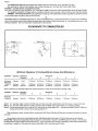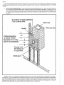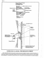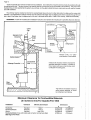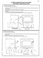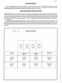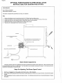
1
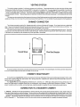
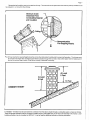
Installation, Operation, and Maintenance Instructions
Model: Quadra-Fire 1800 FreeStandina
I
Nous Avons Aussi Le Manuel en Francais.
Demandez 6 Volre Vendeur
I
--
CONGRATULATION You are now the proud owner of one of the finest inserts in the world for your home -- the
QUADRA-FIRE.
Now, before installinq your insert and buildino your first fire -- record the serial number on the warrantv card.
PLEASE READ A L L O F THE OWNERS MANUAL AND SAFETY NOTES.
IMPORTANT SAFETY NOTES:
1.
2.
3.
4.
5.
6.
7.
8.
9.
10.
11.
12.
13.
(
When installing your stove, particular attention should be paid to fire protection. If this unit is not properly installed,
a house fire may result. For your safety, follow the installation instructions and contact local building or fire officials
about restrictions and installation inspection requirements in your area.
Never use gasoline or similar liquids to start a tire in this unit. K e e all
~ such liauids well away from stove.
During operation ff any pan of the stove starts to glow, tne stove isin an overhid condition. Close the air controls
Comoletelv untl the alowna has stoooed.
OVERFIRING VOIDS- WARRANTY.
..
,
~ o oashe&hould
i
b;, disposed of carefully - using ametal container.
Do not burn wet or green wood. Store wood in dry location.
Do not burn garbage, treated wood, or wood with salt (driftwood, etc.).
DOnot permit creosote or soot to accumulate excessively in the chimney or inside the firebox.
Check yourchimney system thoroughlywhen installing into an existing metalor masonry chimney. Seek professional
advice if in doubt about its condition.
Do not connect this unit to a chimney flue already sewing another appliance.
Comply with all minimum clearances to combustibles as shown in this manual.
Build fire on brick firebox floor -- Do not use grates, andirons or other method to support fuel.
Hot while in operation. Keep children, clothing and furniture away. Contact can cause skin burns.
Do not connect to any air distribution duct or system.
401 N. WYNNE
.
ALADDIN
~~
~~~
~~~~~~
STEEL PRODUCTS. INC.
COLVILLE, WASHINGTON 99114
Page 2
NOTES
Page 3
TABLE OF CONTENTS
Page
Installation Materials Needed .....................................................................................................................
3-4
Installation ......................................................................................................................................................
4
Clearances To Combustibles ......................
.
.. . . . . . . . . . . . . . . . . . . . . . . . . . . . . . . . . . . . . . . . . . . . . . . . . . . . . . . . 4. .
4
Floor Protector .....................
.
.
.
Chimney Connec or
Connection To A Masonry Chimney
Connection To A Metal Prefabricate
Mobile Home Installation Outside Combustio
14
14
Fan Operating Instruction
14
14
15
16
16
16
Wood Selection & Storage ....................
.
.............. . . . . . . . . . . . . . . . . . . . . . . . . . . . . . . . . . . . . . . . . . . . . . . . . . . 16
Brick Patterns ...............................................................................................................................................
I7
Maintenance Instructions
.
.
. . . . . . . . . . . . . . . . . . . . . . . . . . . . . . . . . . . . . . . . . . . . . . . . . . . . 17
Creosote Formation Inspection & Removal ........................ ......... . . . . . . . . . . . . . . . . . . . . . . . . . . . . . . . . . . 17
.
.
.
Door Handle & Glass Replacement
Optional Blower lnstruction
Baffle Removal & Installation
INSTALLATION MATERIALS NEEDED FOR YOUR SAFETY
CHIMNEY CONNECTOR: (Also known as flue pipe or stove pipe) The chimney connector joins the stove chimney. It should be
6 in. diameter 24 MSG black or blued steel 24 gauge minimum.
THIMBLE: A manufactured or site-constructed device installed in combustible walls through which thechimney connector passes
to the chimney. It i s intended to keep walls from igniting.
Page 4
The Quadra-Fire 1800 was safety tested and is listed by Warnock Hersey INC. to UL 1482 and ULC 5627
Also approved for mobile home installation with outside combustion air. (Kit Order #821-0240 & #82i-0230)
WARNING: "DO NOT INSTALL IN SLEEPING ROOM"
CAUTION: THE STRUCTURAL INTEGRITY OFTHE MOBILE HOME FLOOR, WALL AND CEILINGIROOF MUST BE MAINTAINED.
In a residential Installation in Cinada without an outside combustion air kit a source of fresh air into the room shall be provided.
CHIMNEY: APPROVED MASONRY (see specification on page 5), with at least 518 fire clay lining joined with refractory cement
or other listed system suitable for use with wood stoves
OR
PREFABRICATED 6in. listed high temperature (UL 103orULC629M)chimney. Components required by manufacturersforinstallation
such as the chimney support base, firestop (as appropriate), attic insulation shield, insulated tee, etc., are necessary to assure a safe
chimney installation. Use only components manufactured for the chimney.
CLEARANCE TO COMBUSTIBLES
P
R
F 0
L T
0 E
0 C
R T
------
.
8
Stove
0
!?
FCinhiT
Minimum Clearance To Combustible (In Inches And Millimeters)
Installation
Residential
Residential/
Mobile Hm.
Alcove
Clearance Chimney &
Connector
Standard
Note1
Reduced
Standard
Note 2
Note2&3
A
18'(457mm)
I3
Dimensions
C
D
E
F
24"(610mm) 21"(533mm) i6"(406mm) lY(381mm)
lY(305mm)
12"(305mm) 24"(610mm) Zl"(533mm) lO"(254mm) lY(381mm)
lY(305mm) 24"(610mm) 21"(533mm) lO"(254mm) 15(38imm)
lY(305mm)
lY(305mm)
Minimum clearances to combustible material with double-wall chimney connector and top heat shield (Pan #831-1260)
Installation
Residential/
Mobile Hm.
Clearance Chimney &
Connector
Reduced
Note 2 & 3
A
V(203mm)
B
Dimensions
C
D
20(508mm) 17"(432mm) V(152mm)
E
F
1 l"(279mm)
8"(203mm)
Note 1: 6 in. diameter single, minimum 24 MSG steel connector pipe with a listed factory-built chimney or a masonry chimney.
Note 2: 6 in. diameter double wall air insulated connector pipe with listed factow-built chimnev or a masontv chimnev.
t
and
Note 3: Alcove maximum depth of no more than 48", and a" .icoveceiling heightof 84" --with tbp heat s h i e l d i ~ a r#8$-1260)
double-wail chimney connector alcove ceiling height is 72".
When locating your stove, cons~dersafety, convenlence, trafflc flow and the fact that the stove w ~ lneed
l
a ch~mneyand ch~mney
connector.
Floor protector must be non-combust~blemaler~al,extend ng beneatn heater an0 to tne front, sldes and rear as ndlcaleo
AVOID FIRE: Maintain tne aesignated clearance d~stanceto combust~bles.i n s ~ l aon
t mJst NOT to-ch tne cnlmney Tnere m ~ sbe
t
the designated air space clearance around the chimney. This air space around a chimney is necessary to allow natural heat removal
from the area. Insulation in this space will cause a heat buildup which may ignite wood framing.
Page 5
VENTING SYSTEM
The venting system consists of a chimney connector and a chimney. These get extremely hot when the stove is being used.
Temperatures inside the chimney may exceed 2000" in the event of a creosote fire. To protect against the possibility of a house fire,
'he chimney connector and chimney must be properly installed and maintained. A thimble Must be used when a connection is made
,?rougha combustible wall to a chimney. A chimney support package Must be used when a connection is made through the ceiling
to a prefabricated chimney. These accessories are absolutely necessary to provide safe clearances to combustible wall and ceiling
--
-
material
. . . . . . ..
This stove may be connected toa lined masonrychimney or a listed high temperature prefabricatedresidentialtype buildingheating
appliance chimney. Do not connect it to a chimney sewing another appliance. To do so will affectthe safe operation of both appliances.
CHIMNEY CONNECTOR
The chimney connector must be 6 in. diameter pipe with a minimum thickness of 24 gauge. Do not use aluminum or galvanized
steel. They cannot properly withstand the extreme temperatures of a wood fire. Do not use chimney connector pipe as a chimney. You
must connect your stove to a chimney at least equal to those specified in this manual.
Chimnev connector sections must be attached to the stove and to each other with the crimoed end toward the stove. This allows
creosote to iun into the stove and not onto the outside of the pipe. All joints should be secured with three metal screws. Otherwise,
in the event of a creosote fire, the connector may come apart due to movement.
Toward Stove
Flue Gas Directior
i
For .proper
operation
the chimney connector should be as short as possible. Horizontal lenqths
.
.
- of chimney connector should have
a minimum upward slope from the stove of at least 114 in. per foot.
CHIMNEY HEIGHTIDRAFT
To insure that your Quadra-Fire stove burns properly, the chimney draft (Static Pressure) should be approximately 0.100 in. water
column (W.C.) during a high burn and 0.040 in. W.C. during a low burn, measured 6 in. above the top of the stove afler one hour of
operation at each burn setting.
Your Quadra-Fire stove was designed and tested on a 6 in. chimney, 12 - 14 feet high, measured from the top of the stove. The
further your stack height or diameter varies from this configuration, the probability of performance problems increases. In addition,
exterior conditions such as roofline, surrounding trees, prevailing winds and nearby hills can influence stove performance.
CONNECTION TO A MASONRY CHIMNEY
--
1. Chimney Should the stove be connected to a masonry chimney, the chimney should be examined for cracks, loose mortar and
othersignsof deteriorationas well as blockage. Thestove should not be installed until it Is determinedthe chimney lssafe to use. Since
ioversized flue contributes to the accumulation of creosote, the size of the flue should be checked to determine that it is not too large
, the stove. The chimney should also be checkedtoassureit meets the minimumstandardsofthe National Fire ProtectionAssociation
(NFPA) Standard 21 1. The following is a list of the more critical minimum requirements for a properly constructed chimney.
I
I
I
!
Page 6
1.
The masonry wail of the chimney, if brick or modular block, must be a minimum of 4 in. nominal thickness. A mountain or rubble
stone wall must be at least 12 in. thick.
2.
The chimney must have afire clay flue liner (or equivalent) with a minimum thickness of 518 in. and must be installed with refractory
mortar. There must be at least 112 in. air space between the flue liner and the chimnev wail. A eauivalent liner must be a listed
chimney liner system or other approved meterial
518" Fireclay
Flue Liner
Chimney Wall
4" [Nominal]
/
Foundation
A chimney inside the house must have a least 2 in. of clearance to any combustible material. A chimney outside the house must
have at least one in. clearance to anvcombustibie material. Fire stops must be installed at the spaces where the chimnev passes
Page 7
Remember that insulation must not contact the chimney. There must be an air space around the chimney and any insulation must
be at least 2 in. or more from the chimney.
Minimum 2 Inch
Clearance From
Combustible Material
and Insulation
N~ncombustible
Rre-Stopping Materia
A chimney must be the required heightabovethe roof orother obstructionforsafetyandforproper draft operation. Thechimney must
be at least 3 feet higher than the highest point where it passes through the roof and at least 2 feet higher than the highest part of
the roof or structure that is within 10 feet of the chimney, measured horizontally.
CHIMNEY HEIGHT
II. Thimble -- A thimble must be used when the connection from the stove is made through a combustible wall to a masonry chimney.
There are several methods to use for connections made through a combustible wall, two of which are illustrated in this manual. Local
building authorities may be consulted or (NFPA) 21 1 may be used for additional methods of chimney connection.
Page 8
Also, listed prefabricated metal thimbles can be bought for use with wood stoves. The manufacturer's installation instructions lor
a thimble must be strictly followed to assure the safety of the system. Be sure to maintain the designated clearance to combustible
materials.
1.
Brick chimney thimbleassembly -- Constructionof a brick thimble assembly requires 12 in. of brick around afire clay liner.
Be sure the point of penetration allows a 24 in. clearance from the top of the connector to the ceiling. An opening of 30 in. (for
a 6 in. chimney connector) must be cut in the wall to maintain the required 12 in. of brick separation from combustibles. It will
be necessary to cut wall studs and install a header and sill frame to maintain the proper dimensions and to hold the weight of
the brick.
Wood Stud 2 lnches Clearance
.From Chimney Wall
Header
1! 16
Wall
Thimble ASS^^^^\^.
12 Inches of Brick
Separation From Clay
Fireclay Liner
518" ~ i n i m u m
or Eauivalent
'
Minimum 3-112 in. (4 in. nominal) thick solid bricks are to be used. The fire clay liner (ASTM C35 or equivalent) minimum 518 in
wall thickness, must not penetrate into the chimney beyond the inner surface of thechimney flue liner and must be firmly cemented in
place. if it is necessary to cut a hole in the chimney liner, useextreme care to keep it from shattering. Refractory mortar must be used
at the junction to the chimney liner. After the assembly is complete, insert the chimney connector in the fire clay liner. Do not push it
beyond the inside edge of the chimney liner because this will affect the draw of the chimney.
Page 9
- Fireclay Flue Liner
With Airspace
1' Clearance
Thimble12 Inches of Bridc
Door
2. 6 in. solid pack chimney with metal supports as a thimble -- For the method of installation to a masonry chimney shown,
it will be necessarv
,to .ourchase a 8 in. inside diameter 12 in. lonosectionof orefabricatedlisted solidchimnevto use a thimble. Purchase
a wali spacer, trim collar and wali band that are manufactured to fit the chimney section you purchase.
The safety features of this system are the 2 in. air space betweenthe chimney section and combustiblewall and the 1 in. air space
around the chimney connector where the connector passes through the chimney section to the chimney.
The location of the opening through the wall to the chimney must leave a minimum 24 in. verticalclearancebetween the connector
pipe and the ceiling to prevent the ceiling from catching fire.
Cutout a 14-112 in. diameteropening in thewall. It may be necessarytocut wallstudsand installa headerandsill frame tomaintain
the wall support. The hole in the chimney must have at least a 6 in. diameter fire clay liner or equivalent secured with refractorymoriar.
If it is necessary to cut a hole in the chimney liner, use extreme care to keep it from shattering.
First, make the frame for the thimble, being sure it is no smaller than 14-112 in. diameter, to maintain a 2 in. air space around the
chimney section. Attach the wall spacer to the chimney side of the frame. Then insert the frame into the opening, toe-nailing it to the
wall studs. Install the wall band in the framing to secure the chimney section in place. Insert a single section of chimney connector
'9 the chimney through the wall band, being sure it does not protrude into the chimney beyond the edge of the chimney flue lining.
9ly high temperature furnace cement to the end of the chimney section and install it over the connector, through the wall spacer.
I ighten the wall band to hold the chimney section firmly in place and against the chimney. Install the trim collar on the outside of the
opening. Check to assure there is a 1 in. air space between the connector and the chimney section. Also, during installation, always
check to assure that a 2 in. air space is being maintain to the wood framing. Do not fill this space with insulation . Insulation in this air
space will cause a heat buildup which could ignite the wood framing.
Page 10
Minimum Chimney Clearance
to Wall Spacar and
Combustibles 2 Inches
Minimum Clearance 2 lnches
Chimney Flue Liner
Fireday
Liner or
Equivalent '
Chimney Connector
Masonry
Chimney Constructed
to NFPA 21 1
er iF, ,
Clay Flue Liner
Masonry
' Chimney
Wall Spacer
Wall Band To
Secure Chimney
Section
CONNECTION TO A METAL PREFABRICATED CHIMNEY
When a metal prefabricatedchimney is used, the chimney manufacturer's installation instruction must be followed precisely. You
must also purchase (fromthe same manufacturer)and install the ceiling support packageor wall pass through and "T" section package.
firestops (when needed), insulation shield, roof flashing, chimney cap, elc. Maintain the proper clearance to the structure as specified
by the manufacturer. This clearance is usually a minimum of 2 in., although it may vary by manufacturer or for certain components.
Page 11
Note'l: 6 in. diameter, minimum 24 MSG steel connector pipe with a listed factory-built chimney for a masonry chimney.
Note 2: 6 in. diameter double wall air insulated connector pipe with listed factory-built chimney or a masonry chimney.
Note 3: Alcove maximum depth of no more than 48", and an alcove ceiling height of 84" --with top shield (Part #831-1260) and doublewall chimney connector alcove ceiling height is 72".
A
NOTE 1:
NOTE 2:
NOTE 3:
16 in.
I 0 in.
6 in.
B
406mm
254mm
150mm
18 in.
12 in.
8 in.
C
457mm
305mm
200mm
18 in.
10 in.
8 in.
457mm
254mm
200mm
This method of installation requires a
wall pass through device, a wall support package, and insulated " T section and a roof flashing.
On OvtrxJe Wall
Page 12
There are basically two methods of metal chimney installation. One method is to install the chimney inside the residence thtough
the ceiling and the roof. The other method is to install an exterior chimney that runs up the outside of the residence. The components
illustrated may not look exactly like the system you purchase, but they demonstrate the basic components you will need for a proper
and safe installation.
The chimney must be installed so that it is the required height above the roof or other obstruction for safety and for proper draft
operation. The requirement is that the chimney must be at least 3 feet higher than the highest point where it passesthrough the roof
and at least 2 feet higher than the highest part of the roof or structure that is within 10 feet of the chimney, measured horizontally.
REMEMBER: Follow the manufacturer's installation instruction and maintain the manufacturer's specified clearance distances.
Lisled Chimney
Listed
Maintain 2 Inch
Celliq SuppoR
Chimney
Conneclw
,-
TO st0
Connection
*
\
Maintain a Min. of 2 Clearance between Combustibles.
Install an attic insulation shield to maintain the
specified clearance to insulation. Insulation in
this air space will cause a heat buildup which
could ignite the ceiling joists.
I
- A -
This method of installation requires a
ceiling support package, an insulation shield and roof flashing.
Minimum Clearance To Combustible Materials
(In inches & mm) For Quadra-Fire 1800
Installation
Clearance
Chimney & Connector
Residential
Standard
Note: 1
ResidentialIMobile
Reduced
Note: 2
Alcove
Standard
Note: 2 & 3
ResidentiaiIMobiie Home with double-wail connector and top heat shield
SEE Page 3 For Notes
Dimensions
A
B
18(457mm)
16(406mm)
lZ"(305mm)
lO"(254mm)
lZ'Y305mm)
6"f 152mm)
8(203mmj
t~i152mmj
Page 13
OUTSIDE COMBUSTION AIR IS REQUIRED
FOR MOBILE HOME INSTALLATION
Order n821-0230 Pedesta , Rear lntane
Oraer n821-0240 Pedestal. Thru Floor Intake
Position the two side channels over the side air intakes and thru the holes in the sides of the pedestal and attach with
(2) 8-32 screws.
Mount front cover over the front air intake with (2) 114"-20 screws.
Mount cover plate over the opening in the rear of the pedestal. (This plate may have a 3 feet tube for thru-the-wall
installation
...-. .- ...
. ..I
Seal the sides of the pedestal base with fiberglass rope suppled.
Cover hole in hearth beneath the pedestal with rodent screen. (Thru-the-floor installation only.)
~
Order #831-1310 Leg, Rear lntake
Order #831-1300 Leg, Thru-Floor lntake
Position the two side channels over the side air intakes and thru the holes in the sides of the bottom pan an attach with
(2) 8-32 screws.
Mount front cover over the front air intake with (2) 114"-20 screws.
Mount floor or wall intake on underside of bottom pan and connect to ducting.
Page 14
IMPORTANT, PLEASE READ BEFORE USING STOVE
In recent years there has been an increasingconcern about the quaiityof air. Much of the blame for poor air quality has been placed
on the burning of wood for home heating. In order to improve the situation, we at Quadra-Fire have developed cleaner-burning
woodstoves that surpass the requirements for emissions established by agencies governing air quality.
These woodstoves, like any other appliance, must be operated properly in order to insure that they perform the way they should.
Improper operation can turn any woodstove into a smoldering environmental hazard.
It helps to know a little about the actual process of burning in order to understand what goes on inside a stove. The first stage of
burning wewillcall the KindiinaStaqg. Thisiswhen the woodisinitiaily heated toa highenough temperaturetoevaporate the moisture
which is found in all wood. The fuel wiil reach the boiling temperature of water (212" F) and wiil not get any hotter until the water is
evaporated. This process takes heat from the coais and tends to cool the stove. Fire requires three things: Fuel. Air and Heat. So
if heat is robbed from the stove during the drying stage, the new load of wood has reduced the chance for a good clean burn. For this
reason it is always best to burn dry seasoned firewood. This isn't always possible. Sometimes the wood isn't dry, so you must open
the control and burn the stove at the high burn setting for a longer time to start the wood burning. Pushing the air control in, opens it.
The next stage of burning, the S e c o n d a ~
S t a w , is the period when the wood gives off flammable gases which burn above the
fuel with bright flames. During this stage of burning it is most important that the flames be maintained and not allowed to go out. This
wiil insure the cleanest possibiefire. If you are adjusting your stovefora low burn rate, you shouldclose down the air to the point where
you can still maintain some flame. If the flames tend to go out, the stove is set too low for your burning conditions.
The final stage of burning is the Charcwl Staqg. This happens when the flammable gases have been mostly burned and the
charcoal remains. This is a naturally clean portion of the burn. The coals burn with hot blue flames. It is very important to reload your
stove while enough lively hot coais remain in order to provide the amount of heat needed to dry and rekindle the next load of wood. It
is best to open the control for a short while before reloading. This livens up the coalbed. You should also break up any large chunks
and distribute the coals so that the new wood is laid on hot coals.
Air quality is important to all of us and if we choose to use wood to heat our homes, we should do so responsibly. To do this we
need to learn to burn our stoves in the cleanest possible way. Doing this wiil allow us to continue using ourwoodstoves for many years
to come.
COMBUSTION AIR SYSTEM
Thecombustionairentersatthe upperfront of the fireboxnearthe topof theglassdoor. This pre-heated airsupplies the necessary
fresh oxygen to keep the wood burning and mix with the unburned gases, heiping to create secondary, tertiary and quaternary
combustions. This air is regulated by the push rod beneath the ash catcher. For more combustion air, push the rod in. For less
combustion air, pull the rod out.
FAN OPERATING INSTRUCTIONS
If your Quadra-Fire stove is equipped with a fan, you should follow three guidelines:
I.
Initial (Cold) Startup: Leave fan off until your stove is hot and a good coaibed has been estabiished. The fan may be turned
on approximately 30 minutes after loading the unit with fuel.
11.
High Burn Setting: The fan may be ieft on throughout the burn.
Ill. Medium Burn Setting: The fan should be ieft off until a good burn is estabiished, then turned on at a medium or high rate.
IV. Low Burn Setting: The fan tends to cool the stove. if you are using wet wood or a very low burn setting, leave fan off until the
burn is well estabiished. Then if you wish, turn the fan on at a lower rate. Too high a fan setting with low burn rate may adversely
affect emissions.
V.
The fan is equipped with a speed control. The highest fan speed is obtained by turning the speed control on and then adjusting
backtowards off as far as Is possible withoutturning the fan off. Fora low fanspeed, turn thecontrol clockwise as far as possible.
OPERATING TIPS
1.
Here are a few tips on operating your Quadra-Fire stove to obtain the most efficiency with lowest emissions.
Regardless of desired heat output, when loading stove, burn your Quadra-Fire with the air controls wide open for a minimum
of 15 minutes.
2.
Regulate burn rate (heat output) by adjusting the combustion control (center, under ash catcher)
3.
Do Not Burn With Fuel Door Open. Thiscan causeoverfiring and smoke spillage. Smoke spillagecanset off smoke detectors
if they are installed.
Page 15
Low h r n .
Medium Low Burn
Medium Hlah Burn
High Burn
-
Combustion Air C o n t r a
Pull To Stop
Pull To Stoo. Then Push 114 - 112 O ~ e n
Pull To ~ t o bThen
.
Push 112" - 314 ~ b e n
push ~ u lopen
l
NOTE: Caution - If any part of the stove or chimney connector starts to glow, you are in an overfire situation - Close Air Control.
OVERFIRING VOIDS-WARRANN
SUMMARY OF OPERATING INSTRUCTIONS
Aladdin Steel Products is deeply concerned with the air quality in yourcommunity. In orderto maintain clean air, it is very important
to burn your woodstove in the most efficient manner possible. Following these guidelines will ensure environment-friendly operation.
OPACITY
This in the measure of how clean your stove is burning. Opacity is measured in percent. 100% opacity is when an object is totally
obscured by the smoke column from a chimney, aO% opacity means that nosmokecolumn can be seen. As you become familiar with
you stove, you should periodically check the opacity. This will allow you to know how to burn your stove as smoke-free as possible.
WOOD
Burn only dry seasoned wood. Store wood under cover, out of the rain and snow
HIGH BURN RATE
Open (push in) the air control fully. It is important to do this when reloading the stove. Failure to do this could result in excessive
emissions (opacity).
MEDIUM BURN RATE
After a wood load had been burning on high for at least 15 minutes (longer for very large pieces or wet wood), close (pull out) the
control to the desired setting.
LOW BURN RATE
After a wood load has been burning on high for at least 15 minutes (longer for very large pieces or wet wood), close (pull out) the
control gradually making sure to Maintain Flames in the stove. It isvery important to maintain flames in your stove during the first few
hours of a low burn to avoid excessive air oollution.
1
BEFORE YOUR FIRST FIRE
I
Check to see that the baffle is pushed to the rear of the stove and sitting on baffle supports. Make sure insulation blanket is in its
proper location and laying flat at front of baffle.
I
BUILDING A FIRE
There are many ways to build a fire. The basic principle is to light easily ignitable tinder or paper, which ignites the fast-burning
kindling, which in turn ignites the slow-burning firewood. Here is one method that works well:
1.
Place several wads of crushed paper on the firebox floor.
2. Lay small dry sticks of kindling on top.
3. Open combustion air control fully.
4. Makesurethat nomatchesorothercombustibleareinthe immediateareaofthestove. Besure the room isadequately ventilated
and the flue is unobstructed.
5. Light the waded paper in the stove, NEVER light or rekindlestove with kerosene, gasoline, orcharcoal lighter fluid. Results can
be fatal.
.. Once the kindling is burning quickly, add several full length logs three or four inches in diameter. Be careful not to smother the
fire. Stack the pieces of wood carefully -- near enough to keep each other hot, but far enough away to allow adequate air flow
between them.
7. When ready to reload the stove, add more logs. Large logs burn slowly, holding afire longer. Small logs burn fast and hot, giving
quick heat.
i
i
I
Ii
ii
i!
i
I
Page 16
8. Adjust the combustion air control. The more you close down the control, the lower and slower the fire will burn. The more open
the control is, the more heat will be produced. As long as there are hot coals, repeating steps seven and eight will maintain a
continuous fire throughout the season.
NOTE: The special high temperature paint that your stove is finished with wiil cure as your stove heats. You wiil notice an odor and
perhaps see some vapor rise from the stovesurface. This is normal. We recommend that you open a window until the odor dissipates
and the paint is cured.
CARE AND CLEANING OF CERAMIC GLASS
Quadra-Fire stoves are epuipped
. . . with ceramic super heat resistant glass which can only be broken by impact or misuse. Do not
slam stove door or impact the glass. When closing the door, make sureihat logs do not protrude against glass.
Clean glasswith any non-abrasiveglasscleaneravaiiable from your Quadra-Firedealer. Abrasivecleaners may scratch and cause
the glass to crack.
lnspectthe glass regularly. If you find acrackorbreak, immediately put the fireout and returnthe doortoyourdealerfor replacement
of glass before further use. Do not substitute materials for glass replacement.
CARE AND CLEANING OF PLATED SURFACES
Clean 24K gold-plated surfaces with warm soapy water before lighting the first fire. Polishes with abrasive agent will scratch the
finish.
CHIMNEY CLEANING
NOTE: Disconnect flue pipe from stove before cleaning chimney.
ASH REMOVAL
Remove cold ashes (never hot) from the stove by shoveling them into a metal container with a tight-fitting lid. Always treat ashes
as if they contain hot coals and store the container in a non-combustible floor away from combustible material pending final disposal.
FIREBRICK
The firebox of the Quadra-Fire stove is lined with high-quality firebrick which has exceptional insulating properties. There is no
need for a grate. Simply build the fire on the brick floor of your stove.
OVERFIRING
Do not overfire your stove. Using flammable liquids or too much wood, or burning trash in the stove, may result in overfiring. If
the chimney connector or stove glows red or white, the stove is overfired. This condition may ignite creosote in the chimney, possibly
causing a house fire.
If you overfire, immediately close the air control and door, if open, to reduce the air supply to the fire.
BURN WOOD ONLY
Other materials when burned can generate carbon monoxide which can result in carbon monoxide poisoning
WOOD SELECTION AND STORAGE
Dry and well-seasoned wood will not only minimize the chance of creosote formation but also will give you the most efficient fire.
Even d w wood contains 15% moisture by. weight
- and should be burned hot enough to keep the chimney hot for as long as it takes to
dry the wood being burned. It is a waste of energy to burn unseasoned wood of any kind.
Dead wood lying on the forest floor should be considered wet and requires full seasoning time. Standing wood can be considered
213 seasoned. Totell if wood is dry enough to burn, checkthe ends of the logs. If their are cracks radiating in all directions forthe center,
it'sdry. If yourwood sizzles inthe fire, even though thesurface isdry, it may not be fully cured. Splitting of wood before it isstored reduces
drying time. Wood should be stacked that both ends of each piece are exposed to the air, if space is available, since more drying occurs
through thecut ends than through thesides. This is trueeven with wood that has been split. Store wood undercover, such as inashed,
or covered with a tarp, plastic, tarpaper, sheets of scrap plywood, etc.
Page 17
MAINTENANCE
While your Quadra-Fire stove has been designed to provide you with many hours of trouble free operation, there are several
components which require routine checking to maintain your stove in top working condition. These actions are essential to maximize
the overall efficiency (heat output) while minimizing the emissions (smoke) from your stove.
MAINTENANCE INSTRUCTIONS
CREOSOTE Formation - When wood is burned slowly, it producestar and other organicvapors which combinewith expelled moisture
to form creosote. The creosote vapors condense in the relatively cool chimney flue of a newly started fire or from a slow burning fire.
Asaresult.creosote residueaccumulateson thefluelinino. When iqnited, thiscreosote makesanextremelyhotfirewhichmay damage
the chimney or even destroy the house. The chimney connector and chimney should be inspected at least twice monthly during the
heating season to determine if a creosote build up has occurred. If creosote has accumulates, it should be removed to reduce the risk
of a chimney fire.
2. Chimney Inspection and Creosote removal - Inspect the system at the stove connection and at the chimney top. Cooler
surfaces tend to build creosote deposits quicker, so it is important to check the chimney from the top as well as from the bottom. The
creosoteshould be removedwitha brushspecifically designedforthetypeof chimney in use. Achimney sweepcan perform thissewice.
It is also recommended that before each heating season, the entire system be professionally inspected, and cleaned and repaired if
necessary
BRICK PATTERN
4 . 5 X 9"
UNCUT
BACK
BACK
BACK
4.5"X 9
4.5"X 9
4.5"X 9"
UNCUT
3M
X 9"
UNCUT
BO
1.6:
UNCUT
OM
X 9"
RIGHT SlDE
2.875"X 9"
LEFT SIDE
4.5"X 9"
UNCUT
BOTTOM
4.5"X 9"
UNCUT
BOTTOM
4.5"X 9"
UNCUT
RIGHT SlDE
4.Y X 9
UNCUT
LEFT SIDE
4.5"X 9
UNCUT
BOTTOM
4.5"X 9"
UNCUT
BOTTOM
4.5"X 9"
UNCUT
RIGHT SlDE
4.5"X 9"
UNCUT
Page 18
TOP HEAT SHIELD
The top heat shield (Part #831-1260) can be used to reduce clearance to combustible materials. Refer to page 3.
/TRIM
RING (FSl1800 ONLY)
REAR HEAT DEFLECTOR
TOP HEAT SHIELD
\ OUTER WALL
Parts Included:
(1) Top Shield
(1) Trim Ring
(2) "S"Clips
Tools Needed:
No. 2 Phillips screwdriver
1.
2.
3.
4.
5.
Remove the four screws in the rear heat deflector.
Attach the two "S" clips in rear heat shield on the stove.
Set top heat shield on stove and push down into " Sclips.
Place trim ring on top of top heat shield.
Install chimney pipe through hole in top heat shield.
Page 19
Door Handle Asembly
SPRING HANDLE
B
'
LATCH CAM
\
\
NOTE: SPRING HANDLE NOT
1
-
INCLUDED IN ASSEMBLY.
MUST 8E ORDERED SEPARATELY.
WASHERS
DOOR CROSS SECTION
FIBERGLASS
GLASS FRAME
DOOR
GASKET ROPE
GLASS TAB SCREW
\
GLASS TAB
Glass Replacement Instructions
Remove door from stove and lay on a padded flat surface.
Remove glass tabs and screws with a Phillips screwdriver (Turn screws counterclockwise)
3. Lift glass frame pieces and glass out of the door frame.
4. Lay new glass with fiberglass tape around it into door frame making sure the Quadra-Fire logo reads correctly to the
outside.
~~~5. Place glass frame pieces over the fiberglass tape on the edges of the glass. Be sure glass is centered in the opening
(i.e. same space top and bottom, left and right sides).
6. Reinstall screws and glass tabs tight enough to hold things in place.
7. Check again for centering of glass in door frame and give all screws a final tightening.
1.
2.
~~
Page 20
OPTIONAL FREESTANDING BLOWER INSTALLATION
INSTRUCTIONS FOR QUADRA-FIRE STOVES
Tools Required:
No. 2 Phillips screwdriver
318 socket and ratchet, or wrench
The blower is shipped fully assembled and ready for installation.
Step
1.
2.
3.
4.
5.
Remove the blower cover by removing the six No. 8 Phillips head mounting screws.
Position the blower so the mounting clamp slides behind the outer skin centered at the rear of the stove
Tighten the three 114" bolt (318 hex head) to secure the blower to the outer skin.
Reinstall the blower cover and tighten the six Phillips head screws.
Plug the unit in and adjust the fan control as required.
OUTER SKIN
\
NO.8 PHlLLlPS HEAD MACHINE SCREWS
6 PLACES
WlTH COVER REMOVED. HOLD THE BLOWER ASSEMBLY UP SO
THE OUTER SKIN CONTACTS THE MOUNTING BOLTS WERE.
1
/
FAN SPEED CONTROL
IM'HEX HEAD BOLTS J PLACES
ll
Blower Switch Adjustments
The blower switch for this unit is adjusted at the factory and should not require further adjustment. When the blower switch
s turned clockwise it will clickon to high speed. Turn the switch more clockwise to decrease the speed. At full clockwise the fan
;hould blow very gently but should not stop.
Steps For Adjusting The Blower Speed Control
I.
?,
1.
With the unit plugged in turn the speed control knob to slow. (Full clockwise)
With asmail screwdriveradjust the fan speed byturningtheadjustment mechanismthrough the holeon the side of the speed
control.
Adjust the speed so the fan runs slowly, but does not stop. Turn clockwise to slow the fan and counterclockwise to increase
the speed.
Page 21
Baffle Removal & Installation for Model 1800
..
/
~
~
in Quadra-Fire stoves are heavy. The 1800 Baffle weighs 25-lbs. Moving the baffle around inside the stove takes
strength and patience. Removing hardware exposed to combustion processes can be frustrating. if your reason for removing the
baffle is simply to clean the chimney you have alternatives that will save time and effort Read instructions thoroughly before
proceeding
1.
Remove all ash from the Firebox and extinguish all hot
embers before disposal.
2.
Remove the Firebrick from the sides of the stove
4.
To remove the Secondary CombustionTubes, slide them to
one side until one end is out of its hole. Then, while lifting
that end of the baffle plate, pull the tube up over the
Secondary Air Channel and out of the hole at its other end.
Note: The Front and Rear Secondary Tubes differ. Amark
on the tube and the Manifold will insure they are replaced
correctly.
3.
Witha3116"Allen Wrench, removethe SecondaryCombustion Tube Retainer Bolts on the Secondary Air Channel
under the end of each tube. Note: Soak the bolts with
penetrating oil at least 15 minutes before removal.
Page 22
Baffle Removal & Installation for Model 1800
(continued)
5.
To remove the Baffle Plate, use both hands to lift it from the
alignment pin at the center rear. Then tilt it as you slide it to
one side until the other side clears the shelf.
7. Keep the Baffle tilted as you lift it out the door,
6. With one end of the Baffle resting on the bottom firebricks
and the other end against the side of the Firebox, remove
the Kaowool blanket.
8.
To replace the Baffle, reverse Steps 1 through 7. Be sure
the stainless steel extension of the flame spreader is in
place and resting on the Kaowool blanket. Be sure the hole
in the rear of the Baffle is on the alignment pin.
Page 23
ALADDIN STEEL PRODUCTS, INC.
LIMITED WARRANTY
Aladdin Steel Products, Inc., warrants the QUADRA-FIRE 1800 model
against defects in materials or workmanship (except optional electrical
component parts) for a period of five (5) years following the date of retail
purchase. Optional electrical components parts are warranted against
defects in materials or workmanship for a period of one (1) year following
the date of retail purchase. Proof of purchase is required to secure
warranty. To secure this warranty, the purchaser must return the warranty
card within ten (10) days of the purchase to:
Aladdin Steel Products, Inc.
401 North Wynne
Colville, WA. 99114
The manufacturer is responsible only for repair or replacement of the
defective part and may request that the purchaser ship the part to the
manufacturer or authorized repair facility in your state. Warranty claims
should be made to the manufacturer through your authorized dealer. The
manufacture is not responsible for special, incidental or consequential
damage.
Misusing or altering the stove or optional electrical component parts
VOIDS this warranty. This included but is not limited to, using other than
recommended fuels, overheating, and any alterations or modifications.
This warranty does not cover freight, glass, paint, plated surfaces,
gaskets or firebrick.
ALAODIN STEEL PRODUCTS. INC.
401 N. WYNNE
COLVILLE, WASHINGTON 99114