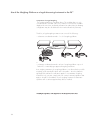
1
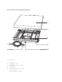
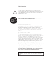
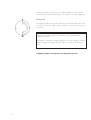
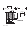
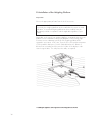
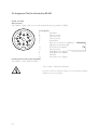
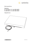
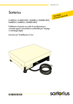
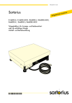
98648-006-06
Sartorius
IS 150 IGG-H, IS 150 IGG-H0CE
IS 300 IGG-H, IS 300IGG-H0CE
Weighing Platforms
Installation and Operating Instructions
98648-006-06
Contents
Page
General View of the Weighing Platform
3
Warranty
Storage and Shipping Conditions
4
4
Safety Instructions
5
Installation Instructions
Ambient Conditions
Conditioning the Weighing Platform
IP67 Protection
6
6
6
6
Getting Started
Unpacking the Weighing Platform
Removing the Transport Locking Devices
Leveling the Weighing Platform
Connecting the Weighing Platform
Safety Precautions
Warm-up Time
7
7
7
8
9
11
12
Operating Limits
Maximum Overload Capacity
Shock Resistance
13
13
13
General Instructions for Integration into
Conveyor Systems
Preload Range (Zero-Setting Range)
Dimensions (Scale Drawings)
Pit Installation of the Weighing Platform
Pit Construction Diagrams
Installation of the Drive-on Ramp YAR 10 IS
14
14
15
16
17
18
Configuring the Weighing Platform
Options for Defining the Weighing
Range Structure
Specifications Chart
General Specifications
Selecting and Affixing the Respective
ID Label
2
19
19
20
22
23
Page
Pin Assignment Chart for the RS-985 Interface 24
Troubleshooting Guide
25
Care and Maintenance
Servicing
Cleaning
Safety Inspection
Information on Recycling
27
27
27
28
28
TÜV Certificates
29
Use of the Weighing Platform
as a Legal Measuring Instrument
Declarations of Conformity
EC Verification – A Service Offered
by Sartorius
Accessories (Options)
36
41
45
46
General View of the Weighing Platform
No. Designation
1
2
3
4
5
6
7
Load plate
Manufacturer's label
Line voltage connector (optional)
Leveling feet
Level indicator
Tag plate for metrological ID label
Connecting cable
(interface port/power supply)
3
With this Sartorius IS weighing platform, you have acquired a high-quality
weighing instrument that features advanced technology. As a rule, you will be
using this weighing platform as part of a modular weighing system.
Please read through these installation and operating instructions before
operating your new weighing platform.
Warranty
Do not miss out on the benefits of our full warranty. Please complete the
warranty registration card, indicating the date of installation, and return the
card to your Sartorius dealer or office.
Storage and Shipping Conditions
Allowable storage temperature:
Allowable storage humidity:
– 10°C ... + 40°C
– 14°F ... + 104°F
98% relative humidity at 40°C (104°F)
After unpacking the weighing platform, please check it immediately for any
visible damage. If you detect any damage, proceed as directed in the section
entitled "Safety Inspection."
It is a good idea to save the box and all parts of the packaging until you have
successfully installed the weighing platform. If you need to ship the weighing
platform for any reason, be sure to unplug all connected cables to prevent
damage.
4
Safety Instructions
!
The seals affixed to this equipment indicate that only authorized service
technicians are allowed to open the equipment and perform maintenance work
so that safe and trouble-free operation of the equipment is ensured and the
warranty remains in effect.
Before opening the weighing cell or A/D converter enclosure, make sure to
unplug the weighing platform from the power supply!
Instructions for Use in Hazardous Areas
Weighing platforms of the series ISI 150IGG-H…and IS300IGG-H comply
with the European Standards EN 50 021: 1999 and EN 5028-1-1-1
according to the Statement of Conformity, No. TüV 01 ATEX 1739 X,
st
nd
including the 1 and 2 Supplements (see “TÜV Certificates”). Therefore, they
are suitable for use in Zones 2 and 22 hazardous areas. Their approval
marking is:
h II 3 GD IP67 Eex nR II T6 T80°C
The type of explosion protection used in these weighing platforms involves
protection of the housing against penetration of potentially explosive vapor. For
this purpose, IP67 protection of the platform must be ensured when it is
connected to the power source. Opening the platform or disconnecting cables
while the scale is plugged into the power supply is strictly forbidden. Please
read the installation instructions in the Annex 35751-000-16-A4. To install the
power supply, please follow the installation instructions given in the section
entitled “Connecting the Weighing Platform” in “Getting Started.”
If you will be operating the platform outside the European Community in a
Zone 2 hazardous area, you must comply with the national electrical code and
applicable safety regulations of your country. Please ask your local Sartorius
service technician, office or dealer for information on the currently valid
regulations applicable in your country.
The weighing platform may not be operated in Zone 0, 1, 20 or 21 hazardous
areas, as it does not have an EX approval certificate for these areas.
Any tampering with the weighing platform by anyone, other than installation of
preload devices, will result in forfeiture of all claims under the manufacturer's
warranty.
5
Installation Instructions
Sartorius dealers or service technicians, who have received special training,
will help you set up the weighing platform and show you how to operate it.
Ambient Conditions
Choose a suitable place to set up the weighing platform. Avoid exposing the
weighing platform to the following ambient conditions:
– Extreme heat radiation
– Extreme vibration
– Places that are difficult to access for cleaning and maintenance
Important Note
If you need to use the weighing platform in areas exposed to heavy traffic
(e.g., fork-lift trucks), you should install a protective frame, consisting of angular
braces, around the weighing platform. To calculate the dimensions for this
protective frame, refer to the section entitled "Dimensions (Scale Drawings)."
Conditioning the Weighing Platform
Do not expose the weighing platform to extreme moisture over long periods.
Moisture in the air can condense on the surfaces of a cold platform whenever it
is brought to a substantially warmer place. If you transfer the weighing
platform to a warmer area, make sure to condition it for about 2 hours at the
new ambient temperature, leaving it unplugged from the power supply.
Afterwards, if you keep the weighing platform connected to the power supply,
the continuous positive difference between the inside of the platform and the
outside will practically rule out the effects of moisture condensation.
IP67 Protection
In conformance with the IP67 protection rating, the weighing platform will
remain leaktight for 30 minutes if immersed at a depth of 1 meter (approx.
3 ft.).
The IP67 protection of the weighing platform is ensured only under the
following conditions:
− The weighing platform is maintained in the original factory condition
− The rubber seals of the weighing cell and the A/D converter are not
perforated
− All cables are securely fastened in place by cable glands
− Both the weighing cell and the A/D converter enclosure are securely closed
6
Getting Started
Unpacking the Weighing Platform
Important Note
To install the weighing platform in a pit, please observe the special
requirements given in the section "Pit Installation."
Unpacking the Weighing Platform
− Remove the weighing platform and the load plate from the packaging
− To transport the weighing platform, lift it on both long sides
− Remove the plastic bags, packaging strips
ÊÊÊÊÊand foam material
Removing the Transport Locking Devices
Set up the weighing platform in the vicinity of your work area and remove the
load plate.
Proceed as follows with the red color-coded transport locking device:
− Remove screw 1
− Loosen screw 2 and turn the angular brace by 180°,
refasten screw 2
− Refasten screw 1 to the lever
Important Note on Transporting the Weighing Platform
Follow the above instructions in reverse order to the transporting
locking device when transporting the weighing platform.
7
Leveling the Weighing Platform Using the Level Indicator
At the place of installation, level the weighing platform using the leveling feet
so that the air bubble is centered within the circle of the level indicator. Check
to ensure that all 4 leveling feet securely touch the surface and that they equally
support the weight of the platform.
− Remove the load plate
− Loosen the locknuts on the leveling feet using a 17 mm open-end wrench
(spanner)
− Extend or retract the leveling feet using a 5 mm Allen wrench (key)
− After leveling the weighing platform, refasten the locknuts securely against
the platform frame
− Replace the load plate
8
Connecting the Weighing Platform
Before initially operating the scale, connect the following cables and
completely assemble the components listed below:
− interface cable to a Sartorius isi industrial terminal or a computer with
special software
− separate power cable for power supply via a Sartorius AC adapter
− components for conveyor systems
Make absolutely sure to unplug the weighing platform from the power supply
before you connect or disconnect any interface cables.
Please note that the person or company who connects any non-Sartoriusapproved indicating and control devices (e.g., a computer) or power supplies
to the weighing platform shall assume all risks and responsibilities associated
with this equipment.
Plug the connecting cable into the connector of a Sartorius isi industrial
terminal. Afterwards, hand-tighten the locking ring. The connecting cable is 6
meters long (approx. 20 feet). To order an extension cable or to customize a
cable to your requirements, refer to the list of accessories or contact Sartorius.
Cable Lengths:
Since you can choose to power the weighing platform via the interface port of
the Sartorius isi industrial terminal or a separate power supply unit, there are a
few restrictions that apply to the cable lengths between these components.
If you use a cable that is longer than 12 meters (∼ 40 feet) between the weighing
platform and the Sartorius isi industrial terminal, each of these components must
be energized by a separate AC adapter.
Note on use in a Zone 11 hazardous area:
The industrial terminal must be mounted securely on a vertical surface so that
the connecting jacks face downwards.
Separate Power Connection for the Weighing Platform
Have your local Sartorius dealer or service technician connect the weighing
platform separately to line current (mains supply). This separate power
connection is required when you use cables that are longer than 12 meters or
if you interface the weighing platform directly with a computer.
9
The following diagrams show the options for powering weighing platforms and
industrial terminals.
Cables for connecting the industrial-grade AC adapter, model ING2, to the
"IS" weighing platform without an extension cord (using the YDO50IS (3m) or
YDO53IS (6m) data output port):
Cables for connecting the industrial-grade AC adapter, model ING2, to the isi
industrial terminal without an extension cord (using the YD050IS (3 m) or the
YD053IS (6 m) data output port):
Cables for connecting the industrial-grade AC adapter, model ING2, only to
the isi industrial terminal with an extension cord:
Connections for cables longer than 12 meters:
10
Safety Precautions
The weighing platform is energized by an external industrial-grade AC
adapter. Make sure that the voltage rating printed on this unit is identical to
your local line voltage. If the voltage specified on the label or the plug design
does not match the rating or standard you use, please contact your local
Sartorius dealer or office. To use a main feeder cable from the ceiling or to
mount a CEE plug, you will have to make arrangements inside your facilities for
installation of such cable equipment.
Use only original Sartorius AC adapters/power supplies identified by the
Sartorius label. Use of AC adapters/power supplies from other manufacturers,
even if these units have an approval identification marking from a national
testing laboratory, requires the consent of an authorized Sartorius service
technician.
For detailed information on further options for powering the weighing platform
(e.g., using local low voltage), contact Sartorius headquarters in Germany
or one of the main offices based in your country.
Hook up the weighing platform to the power supply in conformance with the
installation requirements of your country.
Safety Precautions:
A power supply rated to Industrial Class 2 can be plugged into any electrical
outlet without requiring any additional safety precautions. The ground or earth
terminal is connected to the platform housing, which can be additionally
grounded/earthed, if required.
Install the power cable for connection to an isi industrial terminal or a computer
with adequate protection so that the cable cannot get damaged.
Fixed Power Connection:
If the power cable is permanently installed or secured so that it cannot be
unplugged, the weighing platform must be able to be switched off by a
suitable emergency switch. This emergency switch must be installed near the
weighing platform and be within easy reach. In addition, this switch must be
labeled as an emergency switch. All operators must be shown how to operate
this switch.
Operating the Weighing Platform in Zone 2 Hazardous Areas:
If you need to install the platform in Zone 2 hazardous areas, make sure to
comply with the applicable requirements of your country. Installation of
equipment in Zone 2 must be done by a certified technician.The female plug of
the power cable on the industrial-grade power supply must be secured to the
display unit of the weighing platform. The following requirements must be met
for the plug on the other end of the cable:
– either an explosion-protected plug must be installed;
– or the plug must be detached from the power cable and the power cable
permanently secured to a suitable junction box;.
– or the plug must be secured against accidental disconnection
(see Installation Instructions 35751-000-16 AN in this manual).
Connection to the Power Supply in a Zone 2 Hazardous Area:
Brown (live (L))
Blue (neutral (N))
Yellow/green (protective grounding conductor/protective earth)
11
Whenever possible, avoid wiring your weighing platform into networks that
carry a heavy electrical load (for instance, a compressor or similar equipment).
Warm-up Time
The weighing platform will need to warm up for at least 30 minutes after initial
connection to the power supply (or after a relatively long period without power
connection).
Preparing the Weighing Platform for Verification as a Legal Measuring
Instrument in the EU*:
After initially connecting the weighing platform to the power supply, (or after a
relatively long period outage), allow the platform to warm up for at least 24
hours.
*including the Signatories of the Agreement on the European Economic Area
12
Operating Limits
Maximum Overload Capacity
Sartorius weighing platforms are built so that occasionally loading them
beyond their maximum weighing capacity will not damage them in any way.
The maximum overload capacity of this IS model is 600 kg.
Shock Resistance
Even though Sartorius weighing platforms feature a highly rugged construction,
there are some limits. Avoid dropping objects from considerable height on the
weighing platform and do not expose it to strong side impact. Sartorius
weighing platforms withstand shock according to the shock response spectrum
defined in the IEC68 standard.
13
General Instructions for Integration into
Conveyor Systems
The IS weighing platform is suitable for installation in conveyor systems. Follow
the general instructions given below and refer to the "Dimensions (Scale
Drawings)" to meet the requirements for such installation. Secure the weighing
platform using the appropriate components from the set of fasteners, YAS04 IS.
Any moving or rotating parts intended to be permanently attached to the load
plate must be designed so that they cannot affect the weighing results.
Rotating mechanisms must be properly balanced, for example. In addition, take
care that the fittings do not collide with the parts of the scale platform
mechanism under the load plate. Make sure to remove the load plate from the
platform before drilling.
Any cables or tubing between the weighing platform and other equipment must
not apply any force to the weighing platform. Make sure that cables do not
touch the load plate.
If you install the weighing platform in conveyor systems in Zone 2 or
22Êhazardous areas, you must comply with the applicable safety regulations (e.g.,
in Germany with VDE0165). Special precautions must be taken to prevent the
build-up of static electricity caused by moving parts (e.g., roller conveyors).
Preload Range (Zero-Setting Range)
The weight of components that are securely installed on the weighing platform
is called "preload." The weighing platform must electrically compensate for this
preload so that the entire weighing range is available and so that it is possible
to zero and adjust (calibrate using external weights) the platform. Higher
preloads may result in a reduction in the maximum weighing capacity.
The following weighing capacities must not be exceeded: ÊÊ
− for the IS 150 IGG--H, at least 30 kg weighing capacity must remain
− for the IS 300 IGG-H, at least 60 kg weighing capacity must remain
Ê
ÊÊÊÊÊÊÊÊÊÊÊÊÊÊÊÊÊÊÊÊÊÊÊÊÊÊÊÊÊÊÊÊÊÊÊÊÊÊÊÊÊÊÊÊÊÊÊÊÊÊÊÊÊÊÊ
ÊÊÊÊÊÊÊÊÊÊÊÊÊÊÊÊÊÊÊ
ÊÊÊÊÊÊÊÊÊÊÊÊÊÊÊÊÊÊÊÊÊÊÊÊÊÊÊÊÊÊÊÊÊÊÊÊÊÊÊÊÊÊÊÊÊÊÊÊÊÊÊÊÊÊÊÊNote to Users in the EU *:
ÊÊÊÊÊÊÊÊÊÊÊÊÊÊÊÊÊÊÊÊÊÊÊÊÊÊÊÊÊÊÊÊÊÊÊÊÊÊÊÊÊÊÊÊÊÊÊÊÊÊÊÊÊÊÊÊAlways set the preload prior to verification.
ÊÊÊÊÊÊÊÊÊÊÊÊÊÊÊÊÊÊÊÊÊÊÊÊÊÊÊÊÊÊÊÊÊÊÊÊÊÊÊÊÊÊÊÊÊÊÊÊÊÊÊÊÊÊÊÊÊThe components for integration into a conveyor must already be installed on
ÊÊÊÊÊÊÊÊÊÊÊÊÊÊÊÊÊÊÊÊÊÊÊÊÊÊÊÊÊÊÊÊÊÊÊÊÊÊÊÊÊÊÊÊÊÊÊÊÊÊÊÊÊÊÊÊÊÊthe weighing platform before you connect the platform to the power supply.
ÊÊÊÊÊÊÊÊÊÊÊÊÊÊÊÊÊÊÊÊÊÊÊÊÊÊÊÊÊÊÊÊÊÊÊÊÊÊÊÊÊÊÊÊÊÊÊÊÊÊÊÊÊÊÊÊÊÊÊÊÊÊÊÊ*including
*including the Signatories of the Agreement on the European Economic Area
14
Dimensions in millimeters
15
Pit Installation of the Weighing Platform
Preparation
Choose the appropriate pit frame from the list of accessories.
Note to Users in the EU*
If necessary, the weighing platform can be installed into the pit prior to initial
verification. If a verified weighing platform has been installed, it must be
subsequently verified in compliance with the applicable regulations of your
country.
Depending on the size of your weighing platform, excavate the area where the
platform is to be installed according to the diagrams on the following page.
You must connect a drainage system (5) if the weighing platform will be
operated in a wet area. In this case, slope the floor of the pit (8) at a minimum
of 5% toward the drain point. Position a tube (6) with a min. diameter of
80 mm from a central point of the pit to the location of the display in order
route the signal cable. This will protect the cable, as required.
* in
including
cluding the Signatories of the Agreement on the European Economic Area
16
Installation of a Pit Frame
Remove the screws (7), washers and the metal plates of the pit frame
Place tape over the threads of the pit frame
Aufstellen des Rahmens für Grubeneinbau
Lower the frame into the pit
Ensure that the contact areas of the pit frame (1), (2), (3) and (4) are completely level
– Schrauben (7), Scheiben und Metallplatten am Grubenrahmen entfernen
The pit frame must carry at least half the maximum weighing capacity of the platform on each side
– Gewinde des Grubenrahmens abkleben
Adjust the height by placing thin metal plates (7) underneath the pit frame. Back fill with concrete and allow area to
– Rahmen in die Aussparung einlassen
dry.
– Auflageflächen (1), (2), (3) und (4) müssen exakt in einer waagerechten Ebene liegen
– Tragfähigkeit der einzelnen Auflageflächen müssen jeweils mindestens die Hälfte der gesamten Wägelast sein
Positioning and Connecting the Weighing Platforms (Your Sartorius Service Technician Will Help You )
– Nach exakter Ausrichtung in der Höhe mit Hilfe der Metallplatten und Verankerung, den Rahmen außen mit Beton
ausfüllen
− Remove the load plate, the level indicator and leveling feet
−
−
−
−
−
−
− Take the 4 hexagon bolts, M 10x70, from the set of fasteners, YAS 04 IS, attach the locknuts to them and screw
Aufstellen und Anschluß der Wägeplattform (Unterstützung durch Sartorius Service-Techniker)
them into the threads for the leveling feet (foot screws). Tighten the bolts.
– Waagschale
abnehmen,
und die Stellfüße
− Remove
the transport
locking Libellenhalter
devices as described
on page abschrauben
7.
– 4 Sechskantschrauben M10x70 aus dem Befestigungssatz YAS 04 IS mit den Kontermuttern der Stellfüße versehen
und in
das Stellfußgewinde
einschrauben
− Loosely
attach
the 4 angular braces
to the frame of the weighing platform using the screws (7) and washers from the
–
Transportsichungen
entfernen,
wie
auf Seite 9 beschrieben
set of fasteners.
– 4 the
Befestigungswinkel
Rahmen
Wägeplattform
Schrauben
(7) und
Scheiben
des Befestigungssatzes lose
− Push
connecting cableam
through
theder
tube
(6) and lower mit
the den
weighing
platform
into the
pit frame.
anschrauben
− Loosely attach the angular braces to the pit frame using the screws of the pit frame.
– Verbindungskabel in das Leerrohr (6) einziehen und die Wägeplattform in den Grubenrahmen einlassen
− Center the weighing platform with respect to the pit frame.
– Befestigungswinkel am Grubenrahmen mit den Schrauben des Grubenrahmens lose anschrauben
− Adjust the height of the weighing platform with the 4 hexagon bolts (9), M 10x70. Fix the screws with the locknuts
and
tighten the screws
the angular braces.
– Wägeplattform
zumofGrubenrahmen
mittig ausrichten
– Höhe der Wägeplattform einstellen mit den 4 Sechskantschrauben (9) M10x70, Schrauben kontern und die
− RefitSchrauben
the load plate.
des Befestigungswinkels anziehen
– Waagschale aufsetzen
− Use
the handles
provided
in the set ofdie
fasteners
to remove
the des
loadBefestigungssatzes
plate.
– Zum
Abnehmen
der Waagschale
beiliegenden
Griffe
verwenden
Pit Construction
Grubenplan: Diagrams:
17
17
Installation of the Drive-on Ramp YAR 10 IS
To install the drive-on ramp, YAR 10 IS, use the angular braces and screws
provided. Proceed as shown in the diagrams below.
Loosely attach the angular braces (2) onto the frame of the weighing platform
using the hexagon bolts M8x80 (1), nuts and washers.
Place the side elements of the ramp on the bolts of the angular braces. Adjust
the height of the weighing platform from the ramp using the leveling feet and
securely tighten the fastening screws of the angular braces.
18
Configuring the Weighing Platform
You can adapt the weighing platform to meet your specific requirements –
e.g., metrological specifications, for weighing in international weight units –
and to perform optimally under various ambient conditions as well as process
weighing data. For this reason, final configuration of your Sartorius Modular
Technology equipment is possible only at your dealer's or your particular
facilities.
You can customize the weighing platform (weighing module) via the
Configuration menu using a connected display and control unit,
or using a connected computer with special Sartorius configuration
software (see accessories).
Options for Defining the Weighing Range Structure
SuperRange
This weighing range features exceptionally high resolution; i.e., the weighing
range is subdivided into more than 50,000 digits.
SingleRange
The weighing range is subdivided into 50,000 digits maximum.
Multi-Interval
Weighing ranges with multiple levels of accuracy
The multi-interval function divides the weighing range into 3 ranges, for
example. Each one has a different readability.
In the various ranges, the readability automatically adjusts when the readout for
the weight on the load plate changes (see the "Specifications Chart" for the
particular readability of each range).
After you have pressed the tare key, you will obtain the highest possible
resolution, even when an object is on the load plate of the weighing platform.
You will find the configuration options for your weighing platform in the
"Specifications Charts" on the following pages.
19
Specifications Charts
Access the configuration menu of the conected Sartorius terminal to set the code for the group of specifications of your
choice. Please note that when you change the configuration, this may also change the preload range besides the weighing capacity and the readability. Select the appropriate ID label and affix it to the weighing platform. For direc-tions,
refer to the section entitled "Selecting and Affixing the Respective ID Label." A verifiable scale consists of a weighing
platform (weighing module) and a display and control unit. The scale has the type designation with isoTEST HC BF or
SARTOCOWAT with HCBF : IS 150 IGG-H0CE
Weighing range structure
SuperRange
Weighing range
SingleRange
Standard
Maximum capacity, Max
kg
Readability
g
Multi-Interval
Configurable
150
61
31
1
1
1
150
0 ... 30 kg
10
30 ... 60 kg
20
60 ...150 kg
50
Zero tracking ± 2%
kg
±3
± 1.22
± 0.62
±3
Initial zero-setting range
kg
±10
±10
±10
±10
Preload (electronic) 1)
kg
30
120
150
30
yes
yes
yes
yes
K
K
ISO test function 2)
Metrological specifications:
Accuracy class
g
l
–
Verification scale interval
g
10
10
–
10/20/50
Minimum capacity, Min,
g
50
50
–
200
acc. to CD³)
Temperature range
°C
Select particular group of
specifications (use code)::
0 ... +40
Spec. grp.1*
Spec. grp.2
Spec. grp.3
Spec. grp.4
(10 3 1)
(10 3 2)
(10 3 3)
(10 3 4)
Weighing range structure
SingleRange
Configurable
Weighing range
150
150
61
31
20
50
20
10
±3
±3
±1.22
± 0.62
kg
±10
±10
±10
±10
kg
30
30
120
150
yes
yes
yes
yes
Maximum capacity, Max
kg
Readability
g
Zero tracking ± 2%
kg
Initial zero-setting range
Preload (electronic) 1)
ISO test function ²)
Metrological specifications:
l
l
l
l
Verification scale interval
g
20
50
20
10
Minimum capacity, Min,
g
400
1,000
400
200
Accuracy class
acc. to CD³)
Temperature range
Select particular group of
specifications (use code):
0 ... +40
°C
Spec.grp.5
Spec. grp.6
Spec. grp.7
(10 3 6)
(10 3 7)
(10 3 8)
Spec. grp.8
(10 3 9)
1) With relatively high preloads, the maximum capacity is reduced by 1-kg intervals
2) Up to a max. preload of 120 kg
3) Council Directive 2009/23/EC on non-automatic weighing instruments used in the EU and the Signatories of the Agreement on the European
Economic Area
The weighing platform has a built-in calibration weight. Should external calibration be necessary, you will need one of the following weights:
– Readability of 1 g: 50 kg, accuracy class F1
– Readability of 10 g or more: 50 kg, accuracy class M1
* factory setting
20
IS 300 IGG-H0CE
Weighing range structure
SuperRange
Weighing range
SingleRange
Standard
Maximum capacity, Max
kg
Readability
g
Multi-Interval
Configurable
300
61
31
2
1
1
150
0 ... 30 kg
10
30 ... 60 kg
20
60 ...150 kg
50
Zero tracking ± 2%
kg
±6
± 1.22
± 0.62
±3
Initial zero-setting range
kg
±10
±10
±10
±10
Preload (electronic) 1)
ISO test function 2)
kg
60
120
150
30
yes
yes
yes
yes
Metrological specifications:
Accuracy class
g
–
–
l
Verification scale interval
g
10
10
–
10/20/50
l
Minimum capacity, Min,
g
50
50
–
200
acc. to CD³)
Temperature range
°C
Select particular group of
specifications (use code)::
0 ... +40
Spec. grp.1*
Spec. grp.2
Spec. grp.3
Spec. grp.4
(10 3 1)
(10 3 2)
(10 3 3)
(10 3 4)
Weighing range structure
SingleRange
Configurable
Weighing range
300
300
g
50
100
50
20
Zero tracking ± 2%
kg
±6
±6
± 3.02
± 1.22
Initial zero-setting range
kg
±10
±10
±10
±10
Preload (electronic) 1)
kg
60
60
209
299
yes
yes
yes
yes
l
l
l
l
Maximum capacity, Max
kg
Readability
ISO test function ²)
151
61
Metrological specifications:
Accuracy class
Verification scale interval
g
50
100
50
20
Minimum capacity, Min,
g
1,000
2,000
1,000
400
acc. to CD³)
Temperature range
Select particular group of
specifications (use code)::
0 ... +40
°C
Spec.grp.6
Spec. grp.7
Spec. grp.8
(10 3 6)
(10 3 7)
(10 3 8)
Spec. grp.9
(10 3 9)
1) With relatively high preloads, the maximum capacity is reduced by 1-kg intervals
2) Up to a max. preload of 120 kg
3) Council Directive 2009/23/EC on non-automatic weighing instruments used in the EU and the Signatories of the Agreement on the European
Economic Area
The weighing platform has a built-in calibration weight.
Should external calibration be necessary, you will need one of the following calibration weights:
– Readability of 1 g: 50 kg, accuracy class F1
– Readability of10 g or more: 50 kg, accuracy class M1
* factory setting
21
General Specifications
(for Use in Standard Applications Not Subject to Legal Metrology)
Model
IS 150 IGG-H
IS 300 IGG-H
Readability
g 1
2
Standard deviation
g <± 1
<±2
Linearity
g <±4
<±8
Response time (average)
s < 1.5
< 1.5
Fastest response time
(constant relative accuracy)
s <1
<1
Adaptation to ambient conditions
and application requirements
Data output speed
By selection of 1 of 4 optimized filter levels
s
0.1 - 0.1 - 0.2 - 0.4 (normal output speed)**
(depends on the filter level
selected)
Dust and water protection rating
IP 67, dust-tight and water-proof subject to defined conditions
(certified by TÜV*** in accordance with VDE 0470/EN60529)
Suitable for use in hazardous
areas
Zone 2 and 11
Overload capacity
kg
600
Net weight (without "isi" terminal)
kg
70
approx.
Power requirements (optional)
via A/C adapter, model ING2, 230 VAC or 115 VAC (to be connected
by your dealer or a Sartorius service technician only)
Frequency
Hz
48 – 63
Power consumption
VA
34: maximum, 18: average
VA
10: average
(with isi10,20,30 connected to
an A/C adapter, model ING2)
(only weighing platform
connected to an A/C adapter,
model ING2)
Selectable weight units
g*, kg* , ct, oz, ozt, tlh, tlt, GN, dwt, mg, /lb, tlc, mom, K, tol, bat,
MS, tons
Automatic zero-tracking function
Standard feature
(can be turned off by menu
code)
Built-in interface
RS-485 (standard, XBPI protocol): 8-bit; odd parity;
transmission rates: 9,600...38,400; half-duplex
optional for RS-232 (SBI protocol): 7-bit; parity: even, mark, odd, space;
transmission rates: 150...19,200 baud;
1 or 2 stop bits, software /hardware handshake;
factory setting: 1,200 baud; odd parity; 1 stop bit; hardware handshake
with two characters after "CTS"
*
**
***
22
= Weight unit can also used in legal metrology
= Menu setting "data output speed for converter" is five times faster
= The TÜV is the German Association for Technical Safety and Inspection
Selecting and Attaching ID Plates
The ID plate is to be selected and attached according to the specification block (configuration of scales) and the display and
control unit (terminal). For details of how to position the ID plate on the scales or tag holder, refer to the instructions in
"Plates and Markings".
If display and control units (terminals) of
type TA, models CAIS1, CAISL1, CAIS2, CAISL2, CAIS3, CAISL3 are being used,
EC Type Approval Certificate No. T7899, type SARTOCOWAT is applicable.
ID plate for class
configurations
ID plate for class
configurations
If display and control units (terminals) of
type TN, models CIS2, CSL2, CIS3, CISL3, type TN-X, model CISX3,
type TN-Pro, model Combics Pro,
type isi10, isi20, isi30, type YAC01LA, type YAC01LP, type YAC01FC, type YAC02FC,
PC with Sartorius Win Scale software
EC Type Approval Certificate No. D97-09-018, type iso-TEST is applicable.
ID plate for class
configurations
ID plate for class
configurations
Select and Attach Plate Containing Metrological Data
Plates with the metrological data Max, Min e and d must also be attached near to the display.
Select the plate with the Max, Min e and d metrological data that is suitable for the configuration, cut along the dotted lines
and attach above the display.
The transparent protective film must be stuck over the plate containing the metrological data. The tamper-proof plate
containing the metrological data does not need verification seals.
Examples of attached plates containing metrological data for the possible configurations.
23
Pin Assignment Chart for the Interface RS-485
RS-485, 3-m Cable
Male Connector:
Type C091D, 12-pin round connector with threaded locking ring, Amphenol (IP67))
Pin Assignment
A
B
C
D
E
F
G
H
J
K
L
M
Female Interface Connector (Recommended):
Type C091D, 12-pin, Amphenol (IP67)
RxD-TxD-N
Not Connected
Not Connected
Not Connected
Signal GND
Menu Access Switch for Calibration/
Adjustment (routed externally)
VCC (24V Power Supply)
Not Connected
GND (24V Power Supply)
GND (24V Power Supply)
RxD-TxD-P
VCC (24V Power Supply)
Type of cable: AWG 24 specification
Be sure to follow the instructions given for connecting the weighing
platform to the power supply!
24
Troubleshooting Guide
(For Problems That You Can Fix Yourself)
Problem
Possible Causes
Solution
No segments appear on the
display
– No line current is available
– The AC adapter is not plugged
in
– The weighing platform has
been in the standby mode for
more than 5 minutes
– Check the power supply
– Plug the AC adapter into the platform and into
an electrical outlet
– Turn on the isi industrial terminal using the
on/off switch
The weight display shows "H"
– The load exceeds the capacity
of the weighing platform
– Unload the weighing platform
The weight display shows "L" or
"Err 54"
– The load plate is not on the
weighing platform
– Place the load plate on the platform
The weight display briefly
indicates "Err 01"
– The weight unit selected
requires more decimal places
than are available in the
display
– Select a different weight unit
The weight display briefly
indicates "Err 02"
– One of the requirements for
calibration/adjustment has not
been met (e.g., the weighing
platform is still loaded)
– Check the description of the operating
menu/instruction manual and recalibrate/readjust the weighing platform
– Unload the weighing platform
The weight display briefly
indicates "Err 03"
– Calibration/adjustment was
unable to be completed within
a specific time
– The last function you activated
probably is not allowed for
weighing platforms used as
legal measuring instruments
(legal-for-trade)
– Allow the equipment to warm up and
recalibrate/re-adjust
The error code "ERR 08" is
displayed
– The load on the weighing
platform is too heavy for the
platform to be zeroed
– Check the "Specifications Chart" for the
configuration code you have selected
The error code "ERR 09" is
displayed
– The gross weight value < zero
and the weighing platform is
unloaded, but you cannot tare
– Zero the weighing platform
The error code "ERR 10" is
displayed
Clear the tare memories of your application
– The tare memories for your
application are full, and you
tried to clear the lower-level tare
memory
The error code "ERR 07" is
displayed
– Refer to the operating menu to check whether
this function is allowed for weighing platforms
used as legal measuring instruments
25
Problem
Possible Causes
Solution
The error code "ERR 12" is
displayed
– You tried to store a value in the
tare memory for applications,
although this memory has been
blocked by menu code 2 2 x
– Check the configuration
– You entered a numeric tare that
is not allowed
– Check the value entered
The error code "ERR 17" is
displayed
– Internal calibration is not
possible because the preload
setting is too high
– See "Setting the Preload" in the section on the
operating menu
The error code "ERR 19" is
displayed
– See "Setting the Preload" in the section on the
– The remaining weighing
capacity available is too low
operating menu
because the relatively high
preload setting has reduced the
maximum capacity
The special code "A" remains
displayed
– None of the keys has been
pressed since the weighing
platform was switched on
– Unstable environment (ambient
conditions; e.g., too much
vibration or exposure to
excessive drafts)
The weight readout changes
constantly
The readout of the weighing
result is obviously wrong
– Press any key
– Set up the weighing platform in a different
area
– Access the "Devices" setup menu to adapt the
weighing platform to the particular
environment
– Remove the foreign object
– A foreign object is caught
between the load plate and the
platform frame
– The weighing platform has not – Calibrate/ adjust the weighing platform
been calibrated/ adjusted
– The weighing platform was not – Tare before weighing
tared before weighing
– The weighing platform is tilted
– Level the weighing platform as described
in the instructions
If any other errors occur, please contact your nearest Sartorius service center or your dealer.
26
Care and Maintenance
Servicing
Regular servicing by a Sartorius technician will extend the service life of your
weighing platform and ensure its continued weighing accuracy. Sartorius can
offer you service contracts, with your choice of regular maintenance intervals
ranging from 1 month to 2 years.
Cleaning
Before cleaning the weighing platform, unplug it from the power supply
(disconnect the AC adapter).
To clean the weighing platform when it has been exposed to dry ambient
conditions:
− Use a piece of cloth wet with a commercially available cleaning agent to
wipe down the weighing platform
To clean the weighing platform when it has been in a wet environment:
− Use a commercially available cleaning agent and a gentle, low-pressure jet
of water to hose down the platform afterwards
The weighing platform which has been tested according to
EN 60529 and found to comply with the IP67 protection standard,
will remain leaktight for a maximum of 30 minutes if immersed at a
maximum depth of 1 meter (approx. 3 ft.).
However, pressurized water (e.g., strong jets of water using a hose or
high-pressure cleaning equipment) is not allowed to clean the IP67protected weighing platform.
Never use concentrated acids, bases, solvents or pure alcohol to clean the
weighing platform!
To clean the weighing platform exposed to a corrosive enviroment:
− Regularly remove all traces of corrosive substances from the platform
− Follow the manufacturer's directions provided for the particular disinfectants
and cleaning agents you use to clean the weighing platform
Important Note:
If the water that you use to clean the weighing platform is too hot or cold, the
difference in temperature between the water and the platform can cause
condensation within the platform (according to EN 60529 on IP67 protection).
This condensation may cause the weighing platform to malfunction!
27
Safety Inspection
If there is any indication that safe operation of the weighing platform is no
longer warranted, turn off the power and disconnect it from the power supply
immediately. Lock the equipment in a secure place to ensure that it cannot be
used for the time being.
Safe operation of the weighing platform with the power supply is no longer
ensured when
– there is visible damage to the power supply
– the power supply no longer functions properly
– the power supply has been stored for a relatively long period under
conditions that are different from those specified for "Storage and Shipping"
In this case, notify your nearest Sartorius Service Center or the International
Technical Support Unit based in Goettingen, Germany. Only service
technicians who are authorized by Sartorius and who have access to the
required service manuals are allowed to perform maintenance and repair work
on the equipment.
Information on Recycling
To ensure safe shipment, your weighing platform has been packaged using
environmentally friendly materials. After successful installation of the platform,
you should return this packaging for recycling because it is a valuable source
of secondary raw material.
For information on recycling old weighing equipment, consult your municipal
waste disposal center or local recycling depot.
28
29
30
31
32
33
34
35
Use of the Weighing Platform as a Legal Measuring Instrument in the EU*
Components of a Legal Weighing
The weighing platform is a modular device. This modular device is only
considered to be a verified scale once it has been connected to a suitable
display and control unit, and initial verification has taken place (a deviating
configuration may also be defined for the initial verification by Sartorius).
Therefore, a legal weighing instrument can consist of the following:
– a Sartorius isi industrial terminal + 1 to 3 IS weighing platforms
or
– a Sartorius isi industrial terminal + at least 1 weighing platform + up to 2
further EC- or nationally type-approved weighing instruments
As a weighing instrument, the weighing platform is not allowed to be used for
weighing goods intended for direct sale to the public. Since the platform's
type-approval certifcate for verification applies to non-automatic weighing
instruments only, you must comply with your country's national regulations that
apply to the place of installation of your weighing instrument for automatic
operation with or without supplementary devices installed.
*including the Signatories of the Agreement on the European Economic Area
36
Effect of the Preload on the Acceptability for Verification in the EU*
Only internal adjustment (calibration) is allowed for weighing instruments
verified as legal measuring instruments (refer to the operating instructions for the
particular isi industrial terminal you are using). Therefore, if you use your
weighing platform in a configuration for which you cannot use the ISO test on
account of the relatively high preload, the platform is not acceptable for
verification.
To have your weighing platform verified, you must change the preload setting
before verification only.
The legal basis permitting Sartorius to perform initial verification is constituted
by the following: 1) EC Council Directive No. 2009/23/EC on nonautomatic weighing instruments, which has been applicable within the
harmonized Internal Market of the European Union since 1 January 1993; and
2) the certificate issued by the Metrology Department "Eichwesen" of the
Landesverwaltungsamt of Lower Saxony in Germany.
(MEN, Mess- and Eichwesen Niedersachsen)
Before verification, the respective ID labels and metrology sticker must be
affixed to the area on the instrument(s) as provided.
* including the Signatories of the Agreement on the European Economic Area
37
Approved Auxiliary Measuring Devices
When using the weighing platform as a legal measuring instrument in the EU,
you may connect to it only auxiliary measuring devices that have been
approved for legal metrology in accordance with the EC Type-Approval
Certificate No. D95-09-006:
–
–
–
–
–
–
–
–
–
–
Electromechanical weighing instruments verified for legal metrology
Hand or foot switches for activating the tare function and/or print function
T-connector
Model YTC01, Sartorius
Interface converters
Model Series 7253,
YCC 01- and YCO...,Sartorius
Digital remote displays
Models YRD12Z and
YRD13Z, Sartorius
Printers
Models YDP02-0D,YDP02-0CE,
Sartorius
Industrial terminals of the isi series, used as display and control devices
Checkweighing display with
Model YRD 10Z, Sartorius
color-coded indicators
(does not display weights or other
measured values)
Bar code scanners
Other printers and/or auxiliary measuring devices that are stated on an EC
Type-Approval Certificate for a Sartorius non-automatic weighing instrument,
or other printers and devices whose suitability for connection to weighing
instruments is confirmed by independently issued certificates or reports
provided by a Notified Body in the EU and the Signatories of the Agreement
on the European Economic Area.
For applications not subject to the regulations of legal metrology, any type of
auxiliary device can be connected to the weighing platform:
– D/A converter
Model YDA01Z, Sartorius
– Additional printer, card reader, bar code scanner, remote display, modem,
PC device for data transfer to a central computer, or a similar device.
Information Concerning the EC Machinery Directive
Sartorius balances, scales and weighing platforms are not machines in the
sense of the EC Machinery Directive; however, as individual instruments they
meet the safety requirements of this Directive.
If Sartorius balances, scales and weighing platforms are installed in conveyor
systems, supplemented by auxiliary devices or equipment or otherwise
modified, responsibility for compliance with the EC Machinery Directive and
other safety requirements shall rest with the person who is responsible for the
conveyor system, equipment added and/or modification.
38
Declarations of Conformity
The C Mark on Sartorius Equipment
In 1985, the Council of the European Community approved a resolution
concerning a new approach to the technical harmonization and
standardization of national regulations. The organization for monitoring
compliance with the directives and standards concerning C marking is
governed in the individual EU Member States through the implementation of the
EC Directives adopted by the respective national laws. As of December
1993, the scope of validity for all EC Directives has been extended to the
Member States of the European Union and the Signatories of the Agreement on
the European Economic Area.
Sartorius complies with the EC Directives and European Standards in order to
supply its customers with weighing instruments that feature the latest advanced
technology and provide many years of trouble-free service.
The C mark may be affixed only to weighing instruments and associated
equipment that comply with the applicable Directive(s):
Electromagnetic Compatibility
The equipment meets the requirements of the following Directive:
Council Directive 89/336/EEC "Electromagnetic Compatibility (EMC)"
This Directive regulates the use of equipment that can cause electromagnetic
interference or whose functioning can be influenced by such interference.
Applicable European Standards:
Limitation:
EN 50081-1
of emissions
EN 50081-2
Residential, commercial and
light industry
Industrial environment
Defined immunity EN 50082-1
to interference
EN 50082-2
Residential, commercial and
light industry
Industrial environment
Important Note:
The operator shall be responsible for any modifications to Sartorius equipment
and for any connections of equipment not supplied by Sartorius and must check
and, if necessary, correct these modifications and connections. On request,
Sartorius will provide information on the minimum operating specifications (in
accordance with the Standards listed above for defined immunity to
interference).
41
Additional Directive for Weighing Instruments Used in Legal Metrology:
Council Directive 90/384/EEC "Non-Automatic Weighing Instruments"
This Directive regulates mass determination in legal metrological applications,
e.g., in
– the manufacture of pharmaceuticals
– medicine and health care
– calculation of fees
– price calculation
For the respective Declaration of Type Conformity for weighing instruments that
have been verified by Sartorius for use as legal measuring instruments and that
have an EC Type-Approval Certificate, see page 37.
This Directive also regulates the performance of the EC verification by the
manufacturer, provided that an EC Type-Approval Certificate has been issued
and the manufacturer has been accredited by an officer of a Notified Body
registered at the Commission of the European Community for performing such
verification. On February 15, 1993, Sartorius was
certified foÀÊperforming verification.
For information on the CE mark on Sartorius equipment and legal regulations
currently applicable in your country, and to obtain the names of the persons to
contact, pease ask your local Sartorius office, dealer or service center.
42
43
44
45
46
"EC Verification" - A Service Offered by Sartorius
Our service technicians authorized to perform the verifcation* of your weighing
instruments which are acceptable for legal metrological verification can inspect
and verify the metrological specifications at the place of installation within the
Member States of the European Union and the Signatories of the European
Economic Area.
"New Installation" Service
Initial verification is covered in our "New Installation" service package. In
addition to initial verification, this package provides you with a series of
important services which will guarantee you optimal results in working with your
weighing instrument:
– Installation
– Startup
– Inspection
– Training
– Initial verification
If you would like Sartorius to perform initial verification of your weighing
instrument, contact an authorized service representative. Please refer to the
Sartorius European Service Center Addresses on page 39.
Subsequent Verifications within the European Countries
The validity of the verification will become void in accordance with the
national regulations of the country in which the weighing instrument is used.
For information on verification and legal regulations currently applicable in your
country, and to obtain the names of the persons to contact, please contact your
local Sartorius office, dealer or service center as indicated on the following
page.
* in accordance with the accreditation certificate issued to Sartorius
47
Accessories (Options)
Order No.:
Data interface port with 3-m cable (IP67, RS-485)
and 12-pin round connector
YDO50IS
Data interface port with 3-m cable (IP67, RS-485)
and 12-pin round connector electrically
isolated
YDO51IS
Data interface port with 3-m cable (IP67,
RS-232C/RS-423) and 12-pin round connector
YDO52IS
Data interface port with 6-m cable (IP67, RS-485)
and 12-pin round connector (part of the standard
equipment supplied))
YDO53IS
Extension cable to connect an isi terminal
to a weighing platform; 12-pin round connector
to 12-contact round connector (IP65, 6 m)
YCC 01-ISM6
Round female connector, IP65,
type C091D, 12-contact, Amphenol
69 QC0011
Round male connector, IP65,
type C091D, 12-pin, Amphenol
69 QC0010
Adapter cable, from round connector to PC,
25-pin D-Submini,
0.2 m long (YDO52IS required)
YCC 01-0017D2
For ordering customized cables and accessories, contact your local
Sartorius office or dealer.
48
PC adapter cable, 25-pin D-Submini – 9-contact
6965619
D-Submini 0.25 m long (YDO 52 IS and YCC 01-0017D2
required)
Special menu access locking device, IP65 (for
legal metrology); for external positioning of the menu
access lock on weighing platforms built into systems.
If this device is used, a tag plate for ID labels is not
required.
YAS 02 IS
Upgrade kit for DC power supply to
the weighing platform (without using an external
AC adapter or power supply; the AC adapter does
not come standard with this accessory)
IP67 cable gland (to be installed by an authorized
service technician only)
YAS 03 IS
External rechargeable battery pack; hours of
operation approx. 28
(YAS03IS required)
IP65 AC adapter, 3-m primary cable,
1.5-m secondary cable; to be installed by an authorized
service technician only (YAS03IS required)
for 220 V
for 110 V
Adapter cable for connecting the weighing
platform to a 12-V car battery or to a separate
12-V power source using the terminal leads; cable length:
3.7 m (∼ 12 ft.); with integrated switch and fuse,
reverse battery polarity protection; to be installed, using
the YAS03IS, by an authorized service technician only
YRB 06 Z
6971899
6971500
YRB 01 IS
49
Roller conveyor, with 8 rollers (for the 800 x 600mm
IS weighing platform)
Aluminum
Stainless steel
YRC01IGP
YRC01IGS
Drive-on ramp (1,250 x 600 mm)
YAR 10 IS
Pit frames
– Stainless steel
– Painted
YEG 01 IP
YEG 04 IP
Set of fasteners for pit frame installation
YAS 04 IS
For ordering customized cables and accessories, contact your local Sartorius
office or dealer.
50
51
Sartorius Weighing Technology GmbH
Weender Landstraße 94-108
37075 Goettingen, Germany
Phone +49.551.308.0
Fax +49.551.308.3289
www.sartorius-mechatronics.com
Copyright by Sartorius,
Goettingen, Germany.
All rights reserved. No part
of this publication may
be reprinted or translated in
any form or by any means
without the prior written
permission of Sartorius.
The status of the information,
specifications and illustrations
in this manual is indicated
by the date given below.
Sartorius reserves the
right to make changes to the
technology, features,
specifications and design of the
equipment without notice.
Status:
March 2013
Sartorius Weighing Technology GmbH
Goettingen, Germany
Printed in Germany.
been bleached without any use of chlorine
RS · KT
Publication No.: WIS6011-e13036