1
ControlNet PLC-5
Programmable
Controllers
Catalog Numbers 1785-L20C15,
-L40C15, -L46C15, -L80C15
User Manual
Important User Information
Because of the variety of uses for the products described in this
publication, those responsible for the application and use of these
products must satisfy themselves that all necessary steps have been
taken to assure that each application and use meets all performance
and safety requirements, including any applicable laws, regulations,
codes and standards. In no event will Allen-Bradley be responsible or
liable for indirect or consequential damage resulting from the use or
application of these products.
Any illustrations, charts, sample programs, and layout examples
shown in this publication are intended solely for purposes of
example. Since there are many variables and requirements associated
with any particular installation, Allen-Bradley does not assume
responsibility or liability (to include intellectual property liability) for
actual use based upon the examples shown in this publication.
Allen-Bradley publication SGI-1.1, Safety Guidelines for the
Application, Installation and Maintenance of Solid-State Control
(available from your local Allen-Bradley office), describes some
important differences between solid-state equipment and
electromechanical devices that should be taken into consideration
when applying products such as those described in this publication.
Reproduction of the contents of this copyrighted publication, in whole
or part, without written permission of Rockwell Automation, is
prohibited.
Throughout this publication, notes may be used to make you aware of
safety considerations. The following annotations and their
accompanying statements help you to identify a potential hazard,
avoid a potential hazard, and recognize the consequences of a
potential hazard:
WARNING
!
ATTENTION
!
IMPORTANT
Identifies information about practices or
circumstances that can cause an explosion in a
hazardous environment, which may lead to personal
injury or death, property damage, or economic loss.
Identifies information about practices or
circumstances that can lead to personal injury or
death, property damage, or economic loss.
Identifies information that is critical for successful
application and understanding of the product.
ATTENTION
!
Environment and Enclosure
This equipment is intended for use in a Pollution
Degree 2 industrial environment, in overvoltage
Category II applications (as defined in IEC
publication 60664-1), at altitudes up to 2000 meters
without derating.
This equipment is considered Group 1, Class A
industrial equipment according to IEC/CISPR
Publication 11. Without appropriate precautions,
there may be potential difficulties ensuring
electromagnetic compatibility in other
environments due to conducted as well as radiated
disturbance.
This equipment is supplied as "open type"
equipment. It must be mounted within an enclosure
that is suitably designed for those specific
environmental conditions that will be present and
appropriately designed to prevent personal injury
resulting from accessibility to live parts. The
interior of the enclosure must be accessible only by
the use of a tool. Subsequent sections of this
publication may contain additional information
regarding specific enclosure type ratings that are
required to comply with certain product safety
certifications.
See NEMA Standards publication 250 and IEC
publication 60529, as applicable, for explanations
of the degrees of protection provided by different
types of enclosure. Also, see the appropriate
sections in this publication, as well as the
Allen-Bradley publication 1770-4.1 ("Industrial
Automation Wiring and Grounding Guidelines"),
for additional installation requirements pertaining to
this equipment.
Ethernet is a registered trademark of Intel Corporation, Xerox Corporation, and Digital Equipment Corporation.
ControlNet is a trademark of ControlNet International.
Allen-Bradley, PLC, PLC-2, PLC-3 and PLC-5 are registered trademarks of Rockwell Automation, Inc.
Data Highway Plus, DH+, RSLinx, RSLogix, RSNetWorx, RSNetworx for ControlNet, FLEX I/O , PLC-5/11, -5/20,
-5/20C, -5/26, -5/30, -5/40, -5/46, -5/40L, -5/40C, -5/60, -5/60L, -5/80, -5/80C, -5/86, -5/20E, -5/40E, and -5/80E are
trademarks of Rockwell Automation, Inc.
Rockwell Automation
Support
Before you contact Rockwell Automation for technical assistance, we
suggest you please review the troubleshooting information contained
in this publication first.
If the problem persists, call your local Rockwell Automation
representative or contact Rockwell Automation in one of the following
ways:
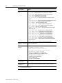
Phone
Internet
United
States/Canada
1.440.646.5800
Outside United
States/Canada
You can access the phone number for your
country via the Internet:
1. Go to http://www.ab.com
2. Click on Product Support
(http://support.automation.rockwell.com)
3. Under Support Centers, click on Contact
Information
⇒
1. Go to http://www.ab.com
2. Click on Product Support
(http://support.automation.rockwell.com)
Your Questions or Comments on this Manual
If you find a problem with this manual, please notify us of it on the
enclosed How Are We Doing form.
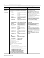
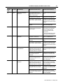
Summary of Changes
Summary of Changes
The information below summarizes the changes to the ControlNet
PLC-5 Programmable Controllers User Manual.
To help you find new and updated information, look for the revision
bars as shown to the left of this paragraph.
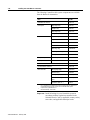
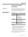
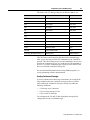
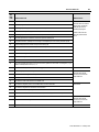
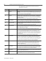
New Information
The following table highlights new information and where its located
in this manual. The following paragraphs describe software
requirements product enhancements.
For This New Information
See
Requested Packet Interval details
Chapter 2
ControlNet Unscheduled Data-Transfer Operations
Scheduled Connection Types
Multicast Inputs
Distributed Keeper Functionality
Understanding ControlNet System Software
Chapter 3
Using the ControlNet I/O Transfer Instruction
Chapter 4
CIP Generic and Generic Bi-directional CIO Command Types
Using Selectable Timed Interrupts
Recovering from Major Fault 200
Using the General Status Indicators
Chapter 5
Relay Cartridge Capability
Appendix A
Processor Status File - Memory Card ID Word 68
Appendix B
Hot Backup Major Fault Codes
ControlNet I/O Map Entry Status Words
Appendix D
Error Messages
Hot Backup Major Fault Codes
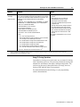
Software and Hardweare
Requirements
Appendix E
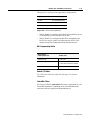
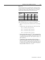
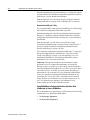
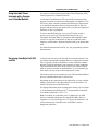
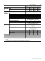
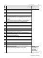
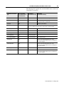
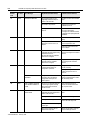
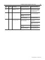
Use the following table to understand specific features that are only
available with specific versions and releases of software and PLC-5
processors:
If you want this feature:
You need both of these
versions of software:
RSLogix5
Standard functionality
Hot Backup (1771 and Flex I/O)
Multicast Outputs
SLC I/O (also with Hot Backup)
2.2 or later
3.21 or later
3.21 or later
5.0 or later
And this PLC-5 Processor
(ControlNet Series F,
RSNetWorx: Revision A or later)
1.8 or later
1.8 or later
3.0 or later
3.0 or later
all
PLC-5/40 or -5/80
PLC-5/20, -5/40 or -5/80
PLC-5/40 or -5/80
1785-UM022B-EN-P - February 2002
soc-ii
Notes
1785-UM022B-EN-P - February 2002
Table of Contents
Installing Your ControlNet
PLC-5 Processor
Chapter 1
Planning to Use Your ControlNet
PLC-5 Processor
Chapter 2
Using This Chapter . . . . . . . . . . . . . . . . . . . . . . . . . . . . . . . . . . . . . . 1-1
Prevent Electrostatic Discharge . . . . . . . . . . . . . . . . . . . . . . . . . . . . . 1-2
Identifying ControlNet PLC-5 Processor Components . . . . . . . . . . . . . 1-3
Before You Install the Programmable Controller . . . . . . . . . . . . . . . . . 1-5
Install or Remove the Battery . . . . . . . . . . . . . . . . . . . . . . . . . . . . . . . 1-6
Setting the I/O Chassis Backplane Switches. . . . . . . . . . . . . . . . . . . . 1-9
Setting the I/O Chassis Configuration Plug . . . . . . . . . . . . . . . . . . . . 1-10
Installing Keying Bands for the Processor. . . . . . . . . . . . . . . . . . . . . 1-10
Selecting the DH+ Station Address of Channel 1A . . . . . . . . . . . . . . 1-11
Specifying the Serial Interface of Channel 0 . . . . . . . . . . . . . . . . . . . 1-12
Selecting the ControlNet Network Address of Channel 2 . . . . . . . . . 1-12
Inserting/Removing the Processor into/from the I/O Chassis. . . . . . . 1-13
Installing a Remote I/O Link . . . . . . . . . . . . . . . . . . . . . . . . . . . . . . . 1-13
Installing a DH+ Link . . . . . . . . . . . . . . . . . . . . . . . . . . . . . . . . . . . . 1-15
Connecting to a ControlNet Network . . . . . . . . . . . . . . . . . . . . . . . . 1-17
Connecting a Programming Terminal . . . . . . . . . . . . . . . . . . . . . . . . 1-19
DH+ Connection . . . . . . . . . . . . . . . . . . . . . . . . . . . . . . . . . . . . . 1-19
Serial Channel . . . . . . . . . . . . . . . . . . . . . . . . . . . . . . . . . . . . . . . 1-20
ControlNet Connection . . . . . . . . . . . . . . . . . . . . . . . . . . . . . . . . . 1-21
Selecting Appropriate Cables . . . . . . . . . . . . . . . . . . . . . . . . . . . . . . 1-22
Serial Cables . . . . . . . . . . . . . . . . . . . . . . . . . . . . . . . . . . . . . . . . 1-22
DH+ Programming Cables . . . . . . . . . . . . . . . . . . . . . . . . . . . . . . 1-23
Remote I/O Cables . . . . . . . . . . . . . . . . . . . . . . . . . . . . . . . . . . . . 1-23
ControlNet Cables . . . . . . . . . . . . . . . . . . . . . . . . . . . . . . . . . . . . 1-23
Using This Chapter . . . . . . . . . . . . . . . . . . . . . . . . . . . . . . . . . . . . . . 2-1
Understanding ControlNet I/O. . . . . . . . . . . . . . . . . . . . . . . . . . . . . . . 2-1
Scheduled Data-Transfer Operations on a ControlNet Network . . . . 2-2
Unscheduled Data-Transfer Operations on a ControlNet Network . . 2-4
Using I/O Forcing Operations . . . . . . . . . . . . . . . . . . . . . . . . . . . . . 2-7
Using Immediate Data-Transfer Operations . . . . . . . . . . . . . . . . . . 2-8
Using Process Control Sample Complete . . . . . . . . . . . . . . . . . . . . 2-9
Clearing the PCSC New Data and PCSC Overflow Bits. . . . . . . . 2-11
Considerations When Using PCSC. . . . . . . . . . . . . . . . . . . . . . . 2-11
Understanding Scheduled Connection Types . . . . . . . . . . . . . . . . . . 2-11
Allowable Scheduled Connection Type Combinations . . . . . . . . . . 2-12
Multiple Processors Can Control I/O . . . . . . . . . . . . . . . . . . . . . 2-13
1785-UM022B-EN-P - February 2002
ii
Table of Contents – ControlNet PLC-5 Programmable Controllers
Understanding Multicast Inputs . . . . . . . . . . . . . . . . . . . . . . . . . . 2-14
Understanding Multicast Outputs . . . . . . . . . . . . . . . . . . . . . . . . . 2-14
Using Multicast Outputs . . . . . . . . . . . . . . . . . . . . . . . . . . . . . . 2-15
Understanding ControlNet I/O Mapping . . . . . . . . . . . . . . . . . . . . . . 2-16
Reserving Space for Non-ControlNet I/O. . . . . . . . . . . . . . . . . . . . 2-16
Processor-Resident Local I/O . . . . . . . . . . . . . . . . . . . . . . . . . . 2-16
Remote I/O. . . . . . . . . . . . . . . . . . . . . . . . . . . . . . . . . . . . . . . . 2-17
Supported ControlNet I/O Sizes . . . . . . . . . . . . . . . . . . . . . . . . . . 2-18
Discrete I/O Data Transfer Mapping . . . . . . . . . . . . . . . . . . . . . 2-19
Non-Discrete I/O Data Transfer Mapping . . . . . . . . . . . . . . . . . 2-19
1771 Modules . . . . . . . . . . . . . . . . . . . . . . . . . . . . . . . . . . . . . 2-20
1747 Modules . . . . . . . . . . . . . . . . . . . . . . . . . . . . . . . . . . . . . 2-20
1794 Modules . . . . . . . . . . . . . . . . . . . . . . . . . . . . . . . . . . . . . 2-20
Other ControlNet Processors . . . . . . . . . . . . . . . . . . . . . . . . . . 2-21
Using I/O Mapping Techniques. . . . . . . . . . . . . . . . . . . . . . . . . . . . . 2-21
Understanding Discrete Mapping . . . . . . . . . . . . . . . . . . . . . . . . . 2-22
Optimizing the I/O Image Table . . . . . . . . . . . . . . . . . . . . . . . . . . 2-23
Optimizing the I/O Image Table without Slot Complementary . . 2-23
Optimizing the I/O Image Table with Slot Complementary. . . . . 2-27
Summary . . . . . . . . . . . . . . . . . . . . . . . . . . . . . . . . . . . . . . . . . . . 2-29
Using the ControlNet PLC-5 Processor in a ControlNet I/O System . . 2-31
Distributed Keeper Functionality. . . . . . . . . . . . . . . . . . . . . . . . . . 2-33
Converting from a Non-ControlNet Remote I/O System
to a ControlNet I/O System . . . . . . . . . . . . . . . . . . . . . . . . . 2-34
Converting from ControlNet Phase 1.0 or 1.25
to ControlNet Phase 1.5 . . . . . . . . . . . . . . . . . . . . . . . . . . . 2-35
Understanding the ControlNet
System Software
1785-UM022B-EN-P - February 2002
Chapter 3
Configuring and Programming Your ControlNet System . . . . . . . . . . . 3-1
Using ControlNet Message Instructions . . . . . . . . . . . . . . . . . . . . . . . 3-1
I/O Configuration Utility . . . . . . . . . . . . . . . . . . . . . . . . . . . . . . . . . 3-2
Uploading and Downloading Software Projects. . . . . . . . . . . . . . . . 3-3
Using RSNetWorx to Perform Verification Activities. . . . . . . . . . . . . 3-4
For More Information . . . . . . . . . . . . . . . . . . . . . . . . . . . . . . . . . . . . . 3-5
Table of Contents – ControlNet PLC-5 Programmable Controllers
Programming Your
ControlNet System
Chapter 4
Monitoring and Troubleshooting
Your ControlNet System
Chapter 5
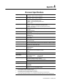
Processor Specifications
Appendix A
Processor Status File
Appendix B
iii
Using This Chapter . . . . . . . . . . . . . . . . . . . . . . . . . . . . . . . . . . . . . . 4-1
Using ControlNet Message Instructions . . . . . . . . . . . . . . . . . . . . . . . 4-1
Multihop Messaging Via the MSG Instruction . . . . . . . . . . . . . . . . . 4-2
Option to Close Communication Connection when MSG is Done . . . 4-3
Understanding the ControlNet PLC-2 Compatibility File . . . . . . . . . 4-3
Using the ControlNet I/O Transfer Instruction . . . . . . . . . . . . . . . . . . . 4-3
Sending Continuous Messages. . . . . . . . . . . . . . . . . . . . . . . . . . . . 4-5
1771 ControlNet Transfers in PIIs and STIs. . . . . . . . . . . . . . . . . . . 4-5
Using ControlNet Immediate Data Input and Output Instructions. . . . . 4-6
Using Selectable Timed Interrupts with a Program
on a ControlNet Network . . . . . . . . . . . . . . . . . . . . . . . . . . . . 4-9
Recovering from Major Fault 200 and 201 . . . . . . . . . . . . . . . . . . . . . 4-9
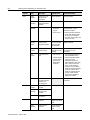
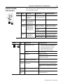
Using This Chapter . . . . . . . . . . . . . . . . . . . . . . . . . . . . . . . . . . . . . . 5-1
Using the General Status Indicators . . . . . . . . . . . . . . . . . . . . . . . . . . 5-1
Using the ControlNet Status Indicators . . . . . . . . . . . . . . . . . . . . . . . . 5-3
Using the DH+/RIO Status Indicators . . . . . . . . . . . . . . . . . . . . . . . . . 5-5
Monitoring ControlNet Configuration and Status. . . . . . . . . . . . . . . . . 5-6
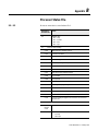
S:0 - S:2 . . . . . . . . . . . . . . . . . . . . . . . . . . . . . . . . . . . . . . . . . . . . . . B-1
S:3-10. . . . . . . . . . . . . . . . . . . . . . . . . . . . . . . . . . . . . . . . . . . . . . . . B-2
S:11 . . . . . . . . . . . . . . . . . . . . . . . . . . . . . . . . . . . . . . . . . . . . . . . . . B-3
S:12 . . . . . . . . . . . . . . . . . . . . . . . . . . . . . . . . . . . . . . . . . . . . . . . . . B-4
S:13-S:24 . . . . . . . . . . . . . . . . . . . . . . . . . . . . . . . . . . . . . . . . . . . . B-11
S:26-S:35 . . . . . . . . . . . . . . . . . . . . . . . . . . . . . . . . . . . . . . . . . . . . B-12
S:36-S:78 . . . . . . . . . . . . . . . . . . . . . . . . . . . . . . . . . . . . . . . . . . . . B-13
S:79-S127. . . . . . . . . . . . . . . . . . . . . . . . . . . . . . . . . . . . . . . . . . . . B-15
ControlNet Instruction Set
Appendix C
ControlNet I/O Transfer Instruction
. . . . . . . . . . . . . . . . . . . . . . . . C-1
Message Instructions on a ControlNet Network . . . . . . . . . . . . . . . C-1
Immediate Data I/O Instructions
. . . . . . . . . . . . . . . . . . . . . . . . . C-2
Instruction Timing and Memory Requirements . . . . . . . . . . . . . . . . . . C-2
1785-UM022B-EN-P - February 2002
iv
Table of Contents – ControlNet PLC-5 Programmable Controllers
ControlNet I/O Map-Entry
Status Words and
Error Messages
Appendix D
Fault Codes
Appendix E
I/O Map-Entry Status Words. . . . . . . . . . . . . . . . . . . . . . . . . . . . . . . . D-1
Error Codes . . . . . . . . . . . . . . . . . . . . . . . . . . . . . . . . . . . . . . . . . . . . D-4
Clearing Faults. . . . . . . . . . . . . . . . . . . . . . . . . . . . . . . . . . . . . . . . . . E-1
Additional Major Fault Codes . . . . . . . . . . . . . . . . . . . . . . . . . . . . . . . E-2
ControlNet Diagnostics
File Layout
1785-UM022B-EN-P - February 2002
Appendix F
Preface
Preface
Introduction
This manual describes how to install your programmable controller
and how to plan for, configure, and use the features of a
1785-L20C15, 1785-L40C15, 1785-L46C15 or 1785-L80C15
programmable controller that are unique to the ControlNet™ network.
When we refer to ControlNet PLC-5 programmable controllers (or
“processors”) in this manual, we mean the phase 1.5 programmable
controllers:
•
Catalog number 1785-L20C15 (or PLC-5/20C™)
•
Catalog number 1785-L40C15 (or PLC-5/40C™)
•
Catalog number 1785-L46C15 (or PLC-5/46C™)
•
Catalog number 1785-L80C15 (or PLC-5/80C™)
For detailed information about features that the ControlNet PLC-5
processors share with Ethernet and Enhanced processors, see the
Enhanced and Ethernet PLC-5 Programmable Controllers User
Manual, publication 1785-6.5.12.
Audience
The information in this manual is intended for engineers and
technicians who are installing, programming, and maintaining a
control system that includes a ControlNet PLC-5 programmable
controller.
You should have a background in control-system applications and a
basic knowledge of:
•
programmable real-time control systems
•
the PLC-5® control system
•
your operation’s required systems and applications
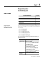
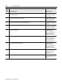
Contents
If you want to read about:
Go to:
Installing your ControlNet PLC-5 processor
Setting switches
Installing communication links
Chapter 1
Planning to use your ControlNet PLC-5 processor
Understanding ControlNet I/O
Using a ControlNet PLC-5 processor
Chapter 2
Understanding the programming software used to configure your ControlNet
system
Chapter 3
Programming your ControlNet system
Chapter 4
1785-UM022B-EN-P - February 2002
P-2
Preface
If you want to read about:
Go to:
Monitoring and troubleshooting your ControlNet system
Using the status indicators
Chapter 5
Processor specifications
Appendix A
Processor status file
Appendix B
ControlNet instructions
Appendix C
ControlNet I/O map table entry status words and error messages
Appendix D
Fault codes
Appendix E
ControlNet diagnostics file layout
Appendix F
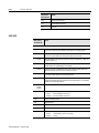
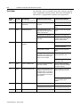
Terminology
Term
Description
Actual Packet Interval (API)
the actual time it takes for the ControlNet network to update the requested data. The largest
binary multiple of the Network Update Time (NUT), smaller or equal to the Requested Packet
Interval (RPI). For more information, see page 2-2.
ControlNet network
communication architecture that allows the exchange of data between Allen-Bradley
Company, Inc. products and certified third-party products
ControlNet PLC-5 processors
references PLC-5/20C, -5/40C, -5/46C and -5/80C programmable controllers phase 1.5
connection
opened communication path between two nodes on a ControlNet network
DData Input File (DIF)
integer file used by ControlNet PLC-5 processors to store discrete and non-discrete input
data. The DIF cannot be forced
Data Output File (DOF)
integer file used by ControlNet PLC-5 processors to store discrete and non-discrete output
data. The DOF cannot be forced
discrete I/O data transfer
type of data transfer in which single units of I/O have discrete relationships with values in
the processor’s data table; uses the processor’s input- and output-image tables (I and O
files); configured on a per-node basis in the ControlNet I/O map table
frame
single data transfer on a ControlNet link
drop cable
cable that connects a ControlNet node to the trunk cable; integral part of 1786 taps
I/O map table
(scanlist configuration)
table that you configure using the programming software to map data from an I/O chassis
and other devices on the ControlNet network to particular data table file addresses
keeper
device that stores and distributes ControlNet configuration data to all nodes on the network.
A minimum of one keeper device is required on each ControlNet network.
link
collection of ControlNet nodes with unique network addresses in the range of 01-99; segments
connected by repeaters make up a link; links connected by bridges make up a network
map table entry
(scanlist entry)
one entry in the I/O map table that you configure using the programming software to map
data from one I/O chassis or other device on ControlNet to particular data table file
addresses
network access port (NAP)
port that provides a temporary ControlNet-network connection through an RJ-45 connector
network address
node’s address on the ControlNet network
network update interval (NUI)
single occurrence of the ControlNet Network Update Time (NUT)
1785-UM022B-EN-P - February 2002
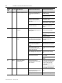
Preface
Term
P-3
Description
network update time (NUT)
smallest repetitive time interval in which data can be sent on the ControlNet network
node
port of a physical device connecting to the ControlNet network that requires a network
address in order to function on the network; a link may contain a maximum of 99 nodes
non-discrete I/O data transfer
type of data transfer in which blocks of data transferred to or from a single I/O module use
integer input and output data table files that you specify; scheduled transfers are configured in
the ControlNet I/O map table, unscheduled transfers make use of ControlNet I/O Transfer (CIO)
instructions
owner
device that controls the outputs of an adapter
processor
any one of the ConrolNet PLC-5 programmable controllers
redundant media
dual-cable system that allows you to receive the best signal over a ControlNet network
repeater
two-port active physical-layer device that reconstructs and retransmits all traffic that it
hears on one ControlNet segment to another segment
Requested Packet Interval
(RPI)
the maximum time allowed for the ControlNet network to update requested data. The RPI is
user-selectable on a per connection basis. For more information, see page 2-2.
scheduled maximum node
(SMAX)
the maximum ControlNet node number that can transmit and receive scheduled data
scheduled transfers
deterministic and repeatable transfers that are continuous and asynchronous to the ladderlogic program scan
scheduled connection types
rack connection - scheduled connection made from the PLC-5C to I/O adapters to some or
all of the discrete I/O on the adapter
module connection - scheduled connection made from the PLC-5C to I/O adapters to
individual modules
segment
trunkline section of ControlNet network with terminators at each end; a segment does not
include repeaters; segments connected by repeaters make up a link
tap
component that connects products to the ControlNet trunk cable; a tap is required for each
node and for each side of a repeater
terminator
75W resistor—mounted in a BNC plug—placed on each end of a ControlNet segment to
prevent reflections from occurring at the ends of the cable
trunk cable
bus or central part of the ControlNet cable system
trunk-cable section
length of trunk cable between any two ControlNet taps
unscheduled maximum node
(UMAX)
the maximum ControlNet node number that can transmit and receive unscheduled data
unscheduled transfers
non-deterministic data transfers through ladder-initiated communication or programming
devices
1785-UM022B-EN-P - February 2002
P-4
Preface
Related PLC-5 Publications
The 1785 PLC-5 programmable-controller and ControlNet
documentation is organized into manuals according to the tasks that
you perform:
Publication
Publication Number
Enhanced PLC-5 Processor System Overview
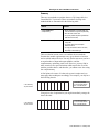
1785-2.36
Enhanced and Ethernet PLC-5 Programmable Controllers User
Manual
1785-6.5.12
ControlNet PLC-5 Programmable Controllers User Manual
1785-UM022B-EN-P
ControlNet Cable System Planning and Installation Manual
1785-6.2.1
ControlNet PLC-5 Programmable Controllers Quick Start
1785-10.6
1785-PLC-5 Programmable Controllers Quick Reference
1785-7.1
For more information about 1785 PLC-5 programmable controllers,
contact your local Rockwell Automation sales office or distributor.
To view or order these publications online, visit:
www.theautomationbookstore.com
Related ControlNet Publications
For detailed information about different aspects of planning and
installing your ControlNet network, see the following publications:
Publication
Publication Number
ControlNet Cable System Component List
AG-2.2
ControlNet Coax Cable System Planning and Installation Manual
1786-6.2.1
ControlNet Network Access Cable Installation Instructions
1786-2.6
ControlNet System Overview
1786-SO001A-EN-P
ControlNet PLC-5 Hot Backup System User Manual
1785-6.5.24
ControlNet Fiber Planning Installation Guide
CNET-IN001A-EN-P
Industrial Automation Wiring and Grounding Guidelines
1770-4.1
System Design for Control of Electrical Noise
GMC-RM001A-EN-P
To view or order these publications online, visit:
www.theautomationbookstore.com
or contact your local Rockwell Automation sales office or distributor.
1785-UM022B-EN-P - February 2002
Chapter
1
Installing Your ControlNet
PLC-5 Processor
Using This Chapter
If you want to read about:
Go to page:
Preventing Electrostatic Discharge
1-2
Identifying the processor components
1-3
What to do before you begin installation
1-5
Installing and disposing of the processor battery
1-6
Setting the I/O chassis backplane switches
1-11
Setting the I/O chassis configuration plug
1-10
Installing keying bands for the processor
1-10
Selecting the Data Highway Plus™ (DH+™) station address
of Channel 1A
1-11
Specifying the serial interface for Channel 0
1-12
Selecting the ControlNet network address of Channel 2
1-12
Inserting/removing the processor into/from the I/O chassis
1-13
Installing a remote I/O link
1-13
Installing a DH+ link
1-15
Connecting to a ControlNet network
1-17
Connecting a programming terminal
1-19
Selecting appropriate cables
1-22
For detailed information about installing chassis and adapters, see the
Enhanced and Ethernet PLC-5 Programmable Controllers User
Manual, publication 1785-6.5.12.
1785-UM022B-EN-P - February 2002
1-2
Installing Your ControlNet PLC-5 Processor
Prevent Electrostatic Discharge
This equipment is sensitive to electrostatic discharge
which can cause internal damage and affect normal
operation. Follow these guidelines when you handle
this equipment:
ATTENTION
!
1785-UM022B-EN-P - February 2002
•
touch a grounded object to discharge potential
static
•
wear an approved grounding wrist strap
•
do not touch connectors or pins on component
boards
•
do not touch circuit components inside the
equipment
•
if available, use a static-safe workstation
•
when not in use, store the equipment in appropriate
static-safe packaging
Installing Your ControlNet PLC-5 Processor
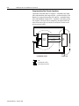
Identifying ControlNet PLC-5
Processor Components
1-3
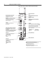
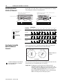
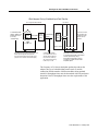
Figure 1.1 and Figure 1.2 show the front panels of the ControlNet
PLC-5 processors.
Figure 1.1 PLC-5/20C Processor Front Panel
Battery Status Indicator
(Red)
Keyswitch-selects processor mode
ControlNet I/O Status Indicator
(Green/Red)
Channel 2 ControlNet Status Indicators
(Green/Red)
ControlNet Network Access Port
(NAP)-RJ45 connector
Processor RUN/FAULT Status Indicator
(Green/Red)
Force Status Indicator
(Amber)
Channel 0 Communication ACTIVE/
FAULT Status Indicator
(Green/Red)
Channel 2
ControlNet Redundant Media
Ports BNC; dedicated
Channel 0
Serial Port-25-pin D-shell; supports standard EIA
RS-232C and RS-423; is RS-422A compatible 1
Memory Module Space
Use this port with ASCII or DF1 full-duplex,
half-duplex master, and half-duplex slave
protocols. The port's default configuration supports
processor programming:
DF1 point-to-point
2400 bit/s
no parity
one stop-bit
BCC error check
no handshaking
Channel 1 Status Indicators (Green/Red)
Battery Compartment
DH+ Programming Terminal Connection
to Channel 1A
8-pin mini-DIN, parallel with 3-pin
connectors of Channel 1A
Channel 1A
3 pin; dedicated DH+
1 Channel 0 is optically coupled (provides high electrical
noise immunity) and can be used with most RS-422A
equipment as long as:
termination resistors are not used
the distance and transmission rate are reduced to
comply with RS-423 requirements
Channel 1B
3 pin; default is remote I/O scanner;
configurable for:
remote I/O scanner
remote I/O adapter
DH+ communication
unused
1785-UM022B-EN-P - February 2002
1-4
Installing Your ControlNet PLC-5 Processor
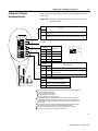
Figure 1.2 PLC-5/40C, -5/46C, and -5/80C Processors Front Panel
Battery Status Indicator
(Red)
Keyswitch-selects processor mode
ControlNet I/O Status Indicator
(Green/Red)
Channel 2 ControlNet Status Indicators
(Green/Red)
ControlNet Network Access Port
(NAP)-RJ45 connector
Channel 2
ControlNet Redundant Media Ports*
BNC; dedicated
Channel 1 Status Indicators (Green/Red)
DH+ Programming Terminal Connection
to Channel 1A
8-pin mini-DIN, parallel with 3-pin connectors
of Channel 1A; use only when Channel 1A is
configured for DH+ communications
Channel 1A
3 pin; default is DH+; configurable for:
remote I/O scanner
remote I/O adapter
DH+ communication
unused
Processor RUN/FAULT Status Indicator
(Green/Red)
Force Status Indicator
(Amber)
Channel 0 Communication ACTIVE/FAULT
Status Indicator
(Green/Red)
Channel 0
Serial Port-25-pin D-shell; supports standard EIA
RS-232C and RS-423; is RS-422A compatible 1
Use this port with ASCII or DF1 full-duplex,
half-duplex master, and half-duplex slave
protocols. The port’s default configuration supports
processor programming:
DF1 point-to-point
2400 bps
no parity
one stop-bit
BCC error check
no handshaking
Memory Module Space
Battery Compartment
Channel 1B
3 pin; default is remote I/O scanner;
configurable for:
remote I/O scanner
remote I/O adapter
DH+ communication
unused
1785-UM022B-EN-P - February 2002
1 Channel 0 is optically coupled (provides high
electrical noise immunity) and can be used with most
RS-422A equipment as long as:
termination resistors are not used
the distance and transmission rate are reduced to
comply with RS-423 requirements
Installing Your ControlNet PLC-5 Processor
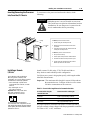
Before You Install the
Programmable Controller
1-5
Before installing your ControlNet PLC-5 processor:
1. Check your processor package, and make sure that you have the
following:
ControlNet PLC-5® Programmable Controller,
1785-L20C15, -L40C15, -L46C15, or -L80C15
Processor
Contents of Tray
1
1
Lithium Battery, 1770-XYC
DIN connector cover
4
Terminating resistors—150Ω1
2 or 42
Terminating resistors—82Ω3
2 or 42
3-pin connectors
Keys
Battery cover with screw
1784-CP7 cable adapter for 1784-CP,
-CP5 cables
ControlNet PLC-5 Programmable Controllers Quick
Start, publication number 1785-10.6
2
1
1
Documentation
1
2
3
Identified by four colored bands: brown, green, brown, and gold
Two with a PLC-5/20C processor, four with PLC-5/40C, -5/46C and -5/80C
processors
Identified by four colored bands: gray, red, black, and gold
If any items are missing or incorrect, contact your local Rockwell
Automation sales office or distributor.
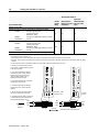
2. Install and connect a chassis and power supply.
Use the following table to find more information about completing
these tasks:
Chassis Type
1771-A1B, -A2B, -A3B, - A3B1, -A4B
Chassis Document
1771-2.210
Power Supply
Power Supply Document
1771-P1
1771-2.6
1771-P2
1771-2.7
1771-P3
1771-2.111
1771-P4
1771-2.111
1771-P4R
1771-5.3
1771-P4S
1771-2.13
1771-P5
1771-2.111
1771-P6R
1771-5.3
1771-P6S
1771-5.11
1771-P7
1771-5.56
1785-UM022B-EN-P - February 2002
1-6
Installing Your ControlNet PLC-5 Processor
Install or Replace the Battery
A 3.0 volt lithium battery (cat. no. 1770-XYC) is included with your
processor.
If the LED on the front of the processor indicates BATT, it means that
the battery must be replaced. You must use an exact replacement
battery (cat. no. 1770-XYC).
ATTENTION
!
Lithium battery requirements:
• do not short, recharge, heat above 85° C,
disassemble or expose contents to water
• use only the 1770-XYC battery in the processor.
DO NOT use any other type or size of battery.
Important: In non-hazardous environments, it may be possible to
replace the battery while the processor is powered so that your
programs are maintained in memory. You may lose your programs if
you remove the battery when power is removed.
WARNING
!
When you connect or disconnect the battery, an
electrical arc can occur. This could cause an
explosion in hazardous location installations. Be sure
that power is removed or the area is nonhazardous
before proceeding.
• For safety information on the handling of lithium
batteries, including handling and disposal of
leaking batteries, refer to Guidelines for Handling
Lithium Batteries, publication AG-5.4
• Store batteries in a cool, dry environment. We
recommend 25° C with 40% or 60% relative
humidity. You may store batteries up to 30 days
between -45° - 85° C, such as during
transportation. To avoid possible leakage, do not
store batteries above 60° C for more than 30 days.
1785-UM022B-EN-P - February 2002
Installing Your ControlNet PLC-5 Processor
1-7
To install or replace the battery:
1. Remove the battery from the shipping bag.
2. Remove the battery cover from the processor.
3. If you are replacing an existing battery, detach the wired clip from
the mating connector on the processor and remove the battery.
4. Connect the new or replacement battery by attaching the wired
clip to the mating connector on the processor.
5. Place the battery and tuck the wires inside the battery area on the
processor.
6. Replace the battery cover.
7. Use a pencil or erasable pen to write the battery installation date
on the battery cover.
WARNING
!
5
When you connect or disconnect the battery, an
electrical arc can occur. This could cause an
explosion in hazardous location installations. Be
sure that power is removed or the area is
nonhazardous before proceeding.
• For safety information on the handling of lithium
batteries, including handling and disposal of
leaking batteries, refer to Guidelines for
Handling Lithium Batteries, publication AG-5.4
• Store batteries in a cool, dry environment. We
recommend 25° C with 40% or 60% relative
humidity. You may store batteries up to 30 days
between -45° - 85° C, such as during
transportation. To avoid possible leakage, do not
store batteries above 60° C for more than 30
days.
1785-UM022B-EN-P - February 2002
1-8
Installing Your ControlNet PLC-5 Processor
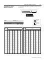
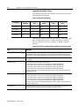
Estimated Battery Lifetimes
Worst-Case Battery-Life Estimates
Processor
Temperature
Power Off 100%
Power Off 50%
Battery Duration1
60° C
173 days
346 days
70 hours
25° C
1.69 years
3.38 years
14.5 days
60° C
92.5 days
185 days
38 hours
25° C
1.25 years
2.5 years
10.8 days
60° C
92.5 days
185 days
38 hours
25° C
1.25 years
2.5 years
10.8 days
60° C
80 days
160 days
33 hours
25° C
1.18 years
2.36 years
10 days
PLC-5/20C
PLC-5/40C
PLC-5/46C
PLC-5/80C
1
The battery status indicator (BATT) warns you when the battery is low. These durations are based
on the battery supplying the only power to the processor—power to the chassis is off—once the
status indicator first lights.
Dispose of a Battery
If you need to dispose of a battery, follow the procedures described in
Guidelines for Handling Lithium Batteries, (pub. no. AG-5.4).
ATTENTION
!
Follow these precautions to prevent the battery from
exploding. An exploding battery exposes toxic,
corrosive and flammable chemicals and causes burns.
• do not incinerate or expose the battery to high
temperatures
• do not solder the battery or leads
• do not open, puncture or crush the battery
• do not charge the battery
• do not short positive or negative terminals together
1785-UM022B-EN-P - February 2002
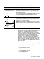
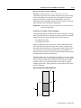
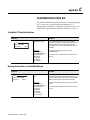
Installing Your ControlNet PLC-5 Processor
Setting the I/O Chassis
Backplane Switches
1-9
Set the I/O chassis backplane switches using a ball-point pen to set
each switch.
Important: Do not use a pencil because the tip can break off and
short the switch.
Switch
Last State
1
O
N
O
F
F
ON
Outputs of this I/O chassis remain in their last state when a hardware
failure occurs.
OFF
Outputs of this I/O chassis are turned off when a hardware failure occurs. 1
1
2
Always OFF
3
4
Switches
5
Addressing
5
OFF
OFF
2 - slot
OFF
ON
1 - slot
ON
OFF
1/2 - slot
ON
ON
Not allowed
6
4
ON
OFF
7
8
Switches
EEPROM Transfer
6
7
OFF
OFF
EEPROM memory transfer to processor memory at powerup. 2 3
ON
ON
EEPROM memory transfers to processor memory if processor
memory not valid.
ON
OFF
EEPROM memory does not transfer to processor memory. 4
Switch
Processor Memory Protection
8
OFF
Processor memory protection disabled.
ON
Processor memory protection enabled. 5
1 Regardless of this switch setting, outputs are turned off when any of the following occurs:
processor detects a runtime error
an I/O chassis backplane fault occurs
you select Program or Test mode
you set a status file bit to reset a local rack
2 If an EEPROM module is not installed and processor memory is valid, the processor's
PROC indicator blinks and the processor sets bit S:11/9 in the major fault status word.
To clear this fault, change the processor from Program mode to Run mode and back to
Program mode.
3 If the processor's keyswitch is set in Remote, the processor enters Remote Run mode
after it powers up and has its memory updated by the EEPROM module.
4 A processor fault (solid red PROC LED) occurs if processor memory is not valid.
5 You cannot clear processor memory when this switch is on.
19309
1785-UM022B-EN-P - February 2002
1-10
Installing Your ControlNet PLC-5 Processor
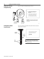
Setting the I/O Chassis
Configuration Plug
Set the I/O chassis configuration plug as follows:
Y N
1. Locate the chassis configuration plug
(between the two left most slots of
the chassis).
2. Set the I/O chassis configuration plug.
USING A
POWER-SUPPLY
MODULE IN
THE CHASSIS?
Y N
The default setting is N (not using a
power-supply module in the chassis).
Y N
Important: You cannot power a single I/O chassis
with both a power-supply module and an external
power supply.
Set Y when you install
a power-supply module
in the chassis.
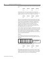
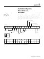
Installing Keying Bands
for the Processor
17075
You receive plastic keying bands with each I/O chassis. Insert the
keying bands as follows:
I/O Chassis
Backplane
Connector
Keying
Bands
(1771-RK)
1785-UM022B-EN-P - February 2002
Set N when you
use an external
power supply.
2
4
6
8
10
12
14
16
18
20
22
24
26
28
30
32
34
36
38
40
42
44
46
48
50
52
54
56
Install a keying band in the left-most
slot between the following pins:
40 and 42
54 and 56
Use these
numbers
as a guide.
!
ATTENTION: A module inserted into a wrong slot
could be damaged by improper voltages connected
through the wiring arm. Use keying bands to prevent
damage to the module.
12062
Installing Your ControlNet PLC-5 Processor
Selecting the DH+ Station
Address of Channel 1A
1-11
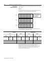
To select the DH+ station address of Channel 1A, set the switches of
assembly SW1.
Side View of PLC-5/20C, -5/40C, -5/46C, -5/80C Switch Assembly SW1
2
1
3
4
5
7
6
Toggle pushed
toward TOP
OFF
To select:
Set switch:
To:
DH+ Station Number
1 through 6
(See below)
Channel 1A DH+ Configuration
7
on (bottom)
off (top)
Switch
DH+
Station
Number
1
2
3
4
5
0
1
2
3
4
5
6
7
10
11
12
13
14
15
16
17
20
21
22
23
24
25
26
27
30
31
32
33
34
35
36
37
on
off
on
off
on
off
on
off
on
off
on
off
on
off
on
off
on
off
on
off
on
off
on
off
on
off
on
off
on
off
on
off
on
on
off
off
on
on
off
off
on
on
off
off
on
on
off
off
on
on
off
off
on
on
off
off
on
on
off
off
on
on
off
off
on
on
on
on
off
off
off
off
on
on
on
on
off
off
off
off
on
on
on
on
off
off
off
off
on
on
on
on
off
off
off
off
on
on
on
on
on
on
on
on
off
off
off
off
off
off
off
off
on
on
on
on
on
on
on
on
off
off
off
off
off
off
off
off
on
on
on
on
on
on
on
on
on
on
on
on
on
on
on
on
off
off
off
off
off
off
off
off
off
off
off
off
off
off
off
off
Toggle pushed
toward BOTTOM
ON
57.6 kbps
230.4 kbps
Switch
6
DH+
Station
Number
1
2
3
4
5
6
on
on
on
on
on
on
on
on
on
on
on
on
on
on
on
on
on
on
on
on
on
on
on
on
on
on
on
on
on
on
on
on
40
41
42
43
44
45
46
47
50
51
52
53
54
55
56
57
60
61
62
63
64
65
66
67
70
71
72
73
74
75
76
77
on
off
on
off
on
off
on
off
on
off
on
off
on
off
on
off
on
off
on
off
on
off
on
off
on
off
on
off
on
off
on
off
on
on
off
off
on
on
off
off
on
on
off
off
on
on
off
off
on
on
off
off
on
on
off
off
on
on
off
off
on
on
off
off
on
on
on
on
off
off
off
off
on
on
on
on
off
off
off
off
on
on
on
on
off
off
off
off
on
on
on
on
off
off
off
off
on
on
on
on
on
on
on
on
off
off
off
off
off
off
off
off
on
on
on
on
on
on
on
on
off
off
off
off
off
off
off
off
on
on
on
on
on
on
on
on
on
on
on
on
on
on
on
on
off
off
off
off
off
off
off
off
off
off
off
off
off
off
off
off
off
off
off
off
off
off
off
off
off
off
off
off
off
off
off
off
off
off
off
off
off
off
off
off
off
off
off
off
off
off
off
off
1785-UM022B-EN-P - February 2002
1-12
Installing Your ControlNet PLC-5 Processor
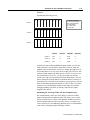
Specifying the Serial
Interface of Channel 0
Specify RS-232C, RS-422A, or RS-423 communication for Channel
0 by setting the switches of assembly SW2.
Bottom View of PLC-5/40C, -5/46C, -5/80C Processor
Switch Assembly SW2
Bottom View of PLC-5/20C Processor
Switch Assembly SW2
Front of processor
Front of processor
1
2
3
4
5
6
7
8
To Specify:
Toggle pushed
toward TOP
OFF
Toggle pushed
toward BOTTOM
ON
1
10
9
2
3
4
5
6
7
8
9
10
Set Switches:
1
2
3
4
5
6
7
8
9
10
ON
ON
ON
OFF
OFF
ON
ON
OFF
ON
OFF
OFF
OFF
ON
OFF
OFF
OFF
OFF
OFF
ON
OFF
ON
ON
ON
OFF
OFF
ON
OFF
OFF
ON
OFF
RS-232C
RS-422A
RS-423
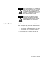
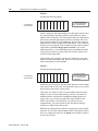
Selecting the ControlNet
Network Address of
Channel 2
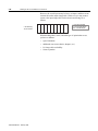
Select your processor’s ControlNet network address by setting the
two 10-digit rotary switches on the top of the processor.
20
30
10
2
1
40
00
50
90
60
80
3
4
0
5
9
6
8
70
Network address 01
is shown
7
NET ADDRESS
For optimum throughput, assign addresses
to your ControlNet nodes in a sequential
order starting with 01.
1785-UM022B-EN-P - February 2002
You can select from as many as 99 network addresses (from 01 to 99)
for a processor on a ControlNet link. 0 is invalid.
Important: Do not power-up the processor if the processor’s
ControlNet network address is set to 0. If you do, you
will not be able to communicate with your processor and
your ladder program will be lost, even if you have a
battery installed. If this happens, select a valid network
address for the processor and cycle power.
Installing Your ControlNet PLC-5 Processor
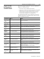
Inserting/Removing the Processor
into/from the I/O Chassis
1-13
To insert/remove the processor into/from the chassis, do the
following:
WARNING
!
If you insert or remove the processor while
backplane power is on, an electrical arc can occur.
This could cause an explosion in hazardous location
installations. Be sure that power is removed or the
area is nonhazardous before proceeding.
To insert a processor into the chassis:
Locking
Bar
1. Lift the locking bar and the ejector tab.
Ejector
Tab
2. Slide the processor into the left-most slot of the
I/O chassis.
3. Press down on the ejector tab, and then close the
locking bar over the processor.
To remove a processor from the chassis:
1. Save processor memory.
2. Remove power to the processor-resident chassis.
3. Disconnect all cables from the processor's ports.
4. Lift the locking bar and the ejector tab, and then
slide the processor from the chassis.
Card Guides
Installing a Remote
I/O Link
Trunk-cable/drop-cable considerations:
When using a trunk-cable/drop-cable
configuration, use 1770-SC station connectors
and follow these cable-length guidelines:
• trunk-cable length—depends on the
communication rate of the link; see Table
Table 1.A
• drop-cable length—30.4 m
(100 cable-ft) maximum
Important: When using a trunk-cable/
drop-cable configuration, set your
communication rate to 57.6K bit/s.
E
MOR
For more information about designing
trunk-cable/drop-cable configurations, see the
Data Highway/Data Highway Plus/Data Highway
II/Data Highway 485 Cable Installation Manual,
publication 1770-6.2.2.
Install a remote I/O link using 1770-CD cable and either a
daisy-chain or trunk-cable/drop-cable configuration.
Verify that your system’s design plans specify cable lengths within
allowable measurements.
Important: The maximum cable length for remote I/O depends on
the transmission rate. Configure all devices on a remote
I/O link to communicate at the same rate.
Table 1.A Correct Cable Length Based on Communication Rate
A remote I/O link using this
communication rate:
Cannot exceed this cable length:
57.6K bit/s
3,048 m (approximately 10,000 ft)
115.2K bit/s
1,524 m (approximately 5,000 ft)
230.4K bit/s
762 m (approximately 2,500 ft)
For proper operation, terminate both ends of a remote I/O link by
using the external resistors shipped with the programmable controller.
Use either a 150Ω or 82Ω terminator.
1785-UM022B-EN-P - February 2002
1-14
Installing Your ControlNet PLC-5 Processor
The maximum number of
Use this
resistor
rating:
If your remote I/O link:
Operates at 230.4K bit/s
Operates at 57.6K or 115.2K bit/s, and no devices listed below are linked
Scanners
1771-SN; 1772-SD, -SD2;
82Ω
1775-SR, -S4A, -S4B;
6008-SQH1, -SQH2
Adapters
1771-AS; 1771-ASB (Series A Only); 1771-DCM
Miscellaneous
1771-AF
Connects to any device listed below:
Scanners
1771-SN; 1772-SD, -SD2;
1775-SR, -S4A, -S4B;
6008-SQH1, -SQH2
150Ω
Adapters
1771-AS; 1771-ASB (Series A Only); 1771-DCM
Miscellaneous
1771-AF
Operates at 57.6K or 115.2K bit/s, and you do not require over 16 physical devices
logical rack
physical devices
numbers that you
that you can connect can scan on the
on the link is:
link is:
32
16
16
16
You can install a remote I/O link two ways:
- trunk cable/drop cable--from the drop cable to the connector screw terminals on the remote I/O connectors of the processor
- daisy chain--to the connector screw terminals on the remote I/O connectors of the processor and then to the remote I/O screw terminals of the next remote
I/O device
To connect remote I/O cable, use the Phoenix MTSB2.5/3-ST 3-pin header connector provided in the accessory kit.
1. Run the 1770-CD cable from the processor
to each remote I/O adapter module or processor
in the remote I/O system.
2. Connect the signal conductor with blue
insulation to the 3-pin connector terminal
labeled 1 on the processor and to each
remote I/O adapter module (or PLC-5
adapter) in the remote I/O system.
3. Connect the shield drain wire to the center
terminal of the 3-pin connector.
4. Connect the signal conductor with clear
insulation to the 3-pin connector terminal
labeled 2.
5. Tie-wrap the remote I/O network cable to
the chassis to relieve strain on the cable.
6. Terminate the remote I/O link by connecting
an external terminator resistor between the
remote I/O terminals labeled 1 and 2.
Blue
Shield
1770-CD
Clear
To another I/O
PLC-5/40C, -5/46C,
-5/80C Processor
Blue
Shield
82W or
150W
resistor
Clear
link device
1770-CD
1785-UM022B-EN-P - February 2002
PLC-5/20C
Processor
Terminate both ends of a remote I/O link
Installing Your ControlNet PLC-5 Processor
WARNING
!
WARNING
!
Installing a DH+ Link
1-15
If you connect or disconnect the 1770-CD cable with
power applied to this processor or the device on the
other end of the cable, an electrical arc can occur.
This could cause an explosion in hazardous location
installations. Be sure that power is removed or the
area is nonhazardous before proceeding.
When used in a Class I, Division 2, hazardous
location, this equipment must be mounted in a
suitable enclosure with proper wiring method that
complies with the governing electrical codes.
Use 1770-CD cable to connect the processor to a DH+ link.
Follow these guidelines while installing DH+ communication links:
•
•
do not exceed these cable lengths:
–
trunk-cable length—3,048 m (approximately 10,000 cable-ft)
–
drop-cable length—30.4 m (approximately 100 cable-ft)
do not connect more than 64 stations on a single DH+ link
1785-UM022B-EN-P - February 2002
1-16
Installing Your ControlNet PLC-5 Processor
Use the 3-pin connector on the processor to
connect a DH+ link. The connector’s port must
be configured to support a DH+
communication link.
You can install a DH+ link two ways:
- trunk cable/drop cable--from the drop cable
to the connector screw terminals on the DH+
connectors of the processor.
- daisy chain--to the connector screw terminals
on the DH+ connectors of the processor.
To make connections, use the Phoenix connector
MTSB2.5/3-ST 3-pin header connector provided
in the accessory kit.
1. Connect the signal conductor with clear
insulation to the 3-pin connector terminal 1
at each end of each cable segment.
PLC-520C
processor
PLC-5/40C, -5/46C
or -5/80C processor
2. Connect the shield drain wire to the center
terminal of the 3-pin connector at both ends
of each cable segment.
3. Connect the signal conductor with blue
insulation to the 3-pin connector terminal 2
at each end of each cable segment.
82W or 150W resistor
WARNING
!
WARNING
!
1785-UM022B-EN-P - February 2002
Clear
Clear
Shield
Blue
Shield
Blue
82W or 150W resistor
If you connect or disconnect the 1770-CD cable with
power applied to this processor or the device on the
other end of the cable, an electrical arc can occur.
This could cause an explosion in hazardous location
installations. Be sure that power is removed or the
area is nonhazardous before proceeding.
When used in a Class I, Division 2, hazardous
location, this equipment must be mounted in a
suitable enclosure with proper wiring method that
complies with the governing electrical codes.
Installing Your ControlNet PLC-5 Processor
Connecting to a
ControlNet Network
1-17
Connect a ControlNet PLC-5 processor to a ControlNet network via a
tap with a 1-m (39.4-in) drop cable.
WARNING
!
WARNING
!
If you connect or disconnect the ControlNet tap cable
with power applied to this processor or the device on
the other end of the cable, an electrical arc can occur.
This could cause an explosion in hazardous location
installations. Be sure that power is removed or the
area is nonhazardous before proceeding.
When used in a Class I, Division 2, hazardous
location, this equipment must be mounted in a
suitable enclosure with proper wiring method that
complies with the governing electrical codes.
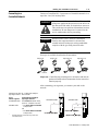
Four taps are available from Rockwell Automation:
Straight T-tap
Straight Y-tap
1786-TPS
Right-angle T-tap
Right-angle Y-tap
1786-TPR
1786-TPYS
1786-TPYR
Important: ControlNet taps contain passive electronics and must be
purchased from Rockwell Automation for the network to
function properly.
After terminating your segments, you connect your node to the
network.
Remove the tap’s dust cap – located on the straight or
right-angle connector – and set it aside.
If your
network supports:
nonredundant media
redundant media
1
Connect the tap’s straight or
right-angle connector:
to the channel A connector on the
processor – channel B is not used1
• from trunk-cable A to channel A
on the processor
and
• from trunk-cable B to channel B
on the processor
BATT
Redundant Media
Nonredundant Media
CH 0
A
CH 0
A
B
Rockwell Automation recommends using channel A for
nonredundant media.
1785-UM022B-EN-P - February 2002
1-18
Installing Your ControlNet PLC-5 Processor
For detailed information about planning and installing your
ControlNet system, see the following publications:
Publication
ControlNet Cable System Component List
AG-2.2
ControlNet Cable System Planning and Installation Manual
1786-6.2.1
ControlNet Network Access Cable Installation Instructions
1786-2.6
ControlNet Fiber Planning and Installation Guide
CNET-IN001A-EN-P
System Design for Control of Electrical Noise
GMC-RM001A-EN-P
Industrial Automation Wiring and Grounding Guidelines
1770-4.1
Terminating Your ControlNet Coaxial Cables CD-ROM
CNET-DM001A-EN-C
To view or order these publications online, visit:
www.theautomationbookstore.com
1785-UM022B-EN-P - February 2002
Publication Number
Installing Your ControlNet PLC-5 Processor
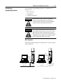
Connecting a
Programming Terminal
1-19
You can connect a programming terminal to a ControlNet PLC-5
processor via a:
•
DH+ connection
•
serial channel
•
ControlNet connection
WARNING
!
WARNING
!
When used in a Class I, Division 2, hazardous
location, this equipment must be mounted in a
suitable enclosure with proper wiring method that
complies with the governing electrical codes.
If you connect or disconnect the DH+ cable with
power applied to this processor or the device on the
other end of the cable, an electrical arc can occur.
This could cause an explosion in hazardous location
installations. Be sure that power is removed or the
area is nonhazardous before proceeding.
DH+ Connection
To attach a personal computer to a ControlNet PLC-5 processor using
a DH+ connection:
8-pin
mini-DIN
connector
8-pin
mini-DIN
connector
Personal computer
DH+ Link
CH 0
Personal computer
PLC-5/20C
Processor
DH+ Link
PLC-5/40C, -5/46C,
-5/80C Processor
1785-UM022B-EN-P - February 2002
1-20
Installing Your ControlNet PLC-5 Processor
When using this
communication card:
Use this cable:
1784-KTX, KTXD
• 1784-CP13
1784-PCMK
• 1784-PCM6
• 1784-PCM5 with 1784-CP7 adapter
1784-PKTX, -PKTXD
• 1784-CP13
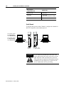
Serial Channel
To program the processor using Channel 0, configure the channel for
RS-232C using DF1 point-to-point protocol.
If your personal computer
has a 9-pin serial port,
use the 1784-CP10 cable.
If your personal computer
has a 25-pin serial port,
use the 1784-CP11 cable.
Personal computer
Personal computer
PLC-5/20C
Processor
WARNING
!
1785-UM022B-EN-P - February 2002
PLC-5/40C, -5/46C
or -5/80 C Processor
If you connect or disconnect the serial cable with
power applied to this processor or the device on the
other end of the cable, an electrical arc can occur.
This could cause an explosion in hazardous location
installations. Be sure that power is removed or the
area is nonhazardous before proceeding.
Installing Your ControlNet PLC-5 Processor
1-21
ControlNet Connection
!
ATTENTION: Do not connect the same
communication card to both the NAP and
a tap on the ControlNet network.
You can connect programming devices to a ControlNet network
through:
•
the ControlNet network access cable (1786-CP)
•
the ControlNet 1784-PCC1 cable
•
a tap on a ControlNet network
Examples of ControlNet Connection Types
Personal computer or
other serial device
and your HMI or
programming software
Personal computer
with 1784-KTCX15 card
(ISA-based) and
your HMI or
programming software
Personal computer
with PCIC card (PCI-based)
and your HMI
or programming software
Laptop computer with
1784-PCC card (PCMCIA-based)
and your HMI or
programming software
PLC-5/40C
1784-PCC1 to PLC-5 (NAP
port or any other NAP port)*
Serial connection
1770-KFC15
Interface
ControlNet Network**
Tap (4 choices)
1786-TPR
Remote I/O link
Data Highway Plus link
Tap (4 choices)
1786-TPR
1794-ACNR15
Flex I/O Adapter
PLC-5/40C
1747-ACNR15
Adapter
1771-ACNR15
Adapter
*A programming terminal connected through this cable is counted as a node and must have a unique address.
**Redundant media not required.
Important: Use the 1786-CP cable when connecting a programming
terminal to the network through a NAP. Using a commercially
available RJ-style cable could result in network failure.
WARNING
!
If you connect or disconnect the ControlNet cable
with power applied to this processor or the device on
the other end of the cable, an electrical arc can occur.
This could cause an explosion in hazardous location
installations. Be sure that power is removed or the
area is nonhazardous before proceeding.
1785-UM022B-EN-P - February 2002
1-22
Installing Your ControlNet PLC-5 Processor
WARNING
!
Selecting Appropriate Cables
When used in a Class I, Division 2, hazardous
location, this equipment must be mounted in a
suitable enclosure with proper wiring method that
complies with the governing electrical codes.
This section lists information about:
•
serial cables
•
DH+ programming cables
•
remote I/O cables
•
ControlNet cables
For more information about cables, see the Enhanced and Ethernet
PLC-5 Programmable Controllers User Manual, publication
1785-6.5.12.
Serial Cables
You can make your own serial cables or purchase them from
Rockwell Automation.
The side label of the processor shows the following table, which
lists Channel 0 (serial port) pin assignments.
Pin
RS-232C
RS-422A
RS-423
Pin
RS-232C
RS-422A
RS-423
1
C.GND
C.GND
C.GND
14
NOT USED
TXD.OUT-
SEND COM
2
TXD.OUT
TXD.OUT+
TXD.OUT
15
3
RXD.IN
RXD.IN+
RXD.IN
16
NOT USED
RXD.IN-
REC COM
4
RTS.OUT
RTS.OUT+
RTS.OUT
17
5
CTS.IN
CTS.IN+
CTS.IN
18
6
DSR.IN
DSR.IN+
DSR.IN
19
NOT USED
RTS.OUT-
NOT USED
7
SIG.GND
SIG.GND
SIG.GND
20
DTR.OUT
DTR.OUT+
DTR.OUT
8
DCD.IN
DCD.IN+
DCD.IN
21
22
NOT USED
DSR.IN-
NOT USED
23
NOT USED
DTR.OUT-
NOT USED
9
10
NOT USED
DCD.IN-
NOT USED
11
24
12
25
13
NOT USED
CTS.IN-
The shading indicates that the pin is reserved.
1785-UM022B-EN-P - February 2002
NOT USED
Installing Your ControlNet PLC-5 Processor
1-23
This processor’s serial port can support these configurations:
Digital Interface
Maximum Cable Length
RS-232C
15 m (approximately 50 ft)
RS-422A (compatible)
61 m (approximately 200 ft)
RS-423
61 m (approximately 200 ft)
Important: Follow these guidelines:
•
When Channel 0 is configured for RS-422A compatibility, do not
use terminating resistors anywhere on the link.
•
When Channel 0 is configured for RS-422A (compatible) and
RS-423, do not go beyond 61 m (approximately 200 ft). This
distance restriction is independent of the transmission rate.
DH+ Programming Cables
When using this
communication card:
Use this cable:
1784-KTX, KTXD
• 1784-CP13
1784-PCMK
• 1784-PCM6
• 1784-PCM5 with 1784-CP7 adapter
1784-PKTX, -PKTXD
• 1784-CP13
Remote I/O Cables
Use 1770-CD or cable for remote I/O. See page 1-13 for more
information.
ControlNet Cables
Several types of RG-6 quad-shield cable may be appropriate for your
ControlNet installation—depending on the environmental factors
associated with your application and installation site.
1785-UM022B-EN-P - February 2002
1-24
Installing Your ControlNet PLC-5 Processor
The following ControlNet cable system components are available
from the Rockwell Automation:
Item1
Cat. No.
ControlNet Coax Tool Kit
1786-CTK
Coax Tap Kit
Right-angle T-tap
1786-TPR
Straight T-tap
1786-TPS
Right-angle Y-tap
1786-TPYR
Straight Y-tap
1786-TPYS
Repeater adapter
1786-RPA
Copper
1786-RPCD
Fiber -short
1786-RPFS
Fiber - medium
1786-RPFM
Fiber ring - long
21786-RPFRL
Fiber ring - extra long
21786-RPFRXL
Dummy load
1786-TCAP
Fiberoptic Repeaters
Low-voltage dc
1786-RPA
RG-6 Quad Shield Cable
Standard-PVC CM-CL2
1786-RG6
Repeaters
ControlNet Network Access Cable—3.05 m (10 ft)
1786-CP
PC Card Cable for 1784-PCC
1784-PCC1
BNC Connectors
1
2
Barrel (plug to plug)
1786-BNCP
BNC/RG-6 plug
1786-BNC
Bullet (jack to jack)
1786-BNCJ
Isolated-bulkhead (jack to
jack)
1786-BNCJI
Terminators (BNC-75Ω)
1786-XT
For a complete list of ControlNet cable system components that are available from
Rockwell Automation and other sources, see the ControlNet Cable System
Component List, publication AG-2.2.
Planned availability - March 2002.
Important: Install all wiring for your ControlNet system in
accordance with the regulations contained in the
National Electric Code (or applicable country codes),
state codes, and applicable municipal codes.
1785-UM022B-EN-P - February 2002
Installing Your ControlNet PLC-5 Processor
1-25
For detailed information about ControlNet cabling, see the following
publications:
Publication
Publication Number
ControlNet Cable System Component List
AG-2.2
ControlNet Cable System Planning and Installation Manual
1786-6.2.1
ControlNet Network Access Cable Installation Instructions
1786-2.6
ControlNet System Overview
1786-2.9
ControlNet Fiber Planning and Installation Guide
CNET-IN001A-EN-P
System Design for Control of Electrical Noise
GMC-RM001A-EN-P
Industrial Automation Wiring and Grounding Guidelines
1770-4.1
Terminating Your ControlNet Coaxial Cable
CNET-DM001A-EN-C
1785-UM022B-EN-P - February 2002
1-26
Installing Your ControlNet PLC-5 Processor
Notes
1785-UM022B-EN-P - February 2002
Chapter
2
Planning to Use Your ControlNet PLC-5
Processor
Using This Chapter
If you want to read about:
Go to page:
Understanding ControlNet I/O
2-1
Understanding Scheduled Connection Types
2-11
Understanding ControlNet I/O mapping
2-16
Using I/O Mapping Techniques
2-21
Using the ControlNet PLC-5 processor in a ControlNet I/O system
2-31
Converting from a non-ControlNet remote I/O system to a
ControlNet I/O system
2-34
Converting from ControlNet phase 1.0 or 1.25 to ControlNet
phase 1.5
2-35
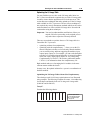
To distinguish phase 1.5 ControlNet processors from earlier phase
processors, new catalog numbers were created for each of the phase
1.5 ControlNet processors: 1785-L20C15, 1785-L40C15, L46C15,
and 1785-L80C15.
ATTENTION
!
Understanding
ControlNet I/O
You cannot mix phase 1.5 and earlier phase (such as
1.0 and 1.25) products on the same ControlNet
network.
The ControlNet system is designed to:
•
provide high-speed, repeatable, deterministic I/O transmission
•
allow control and message information to co-exist on the same
physical media
•
make sure that I/O data transfers are not affected by
-
programming-terminal message activity
-
inter-PLC processor message activity on the network
1785-UM022B-EN-P - February 2002
2-2
Planning to Use Your ControlNet PLC-5 Processor
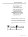
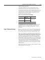
Scheduled Data-Transfer Operations on a ControlNet Network
ControlNet scheduled data transfer on a ControlNet PLC-5 processor:
•
is continuous
•
is asynchronous to the ladder-logic program scan
•
occurs at the actual rate displayed in the Actual Packet Interval
(API) field on the programming software scanlist configuration
screen in RSNetWorx for ControlNet
Important: The Requested Packet Interval (RPI) rate requested for a
connection establishes the data transfer rate on the ControlNet
network. API is determined by RSNetWorx when the schedule is
built. The API will always be the same or less than the RPI.
The API does not imply the actual I/O throughput. I/O data is sent on
the network every API regardless of whether the I/O data has been
refreshed with newer I/O data. I/O throughput time may be slower
due to delays caused by module update times, processor scan times
and adapter to I/O module transfer times.
What Happens During Scheduled Output Data Transfer
Scheduled data transfer
occurs between the PLC-5
and the adapter module in
the I/O chassis. Data may
stay in the private memory
buffer for up to 1 API.
Data from the output-image file is put into
a private memory buffer. New output data
may stay in the data table files up to 1
program scan or until the next housekeeping.
2
1
In scheduled I/O data
transfer, updates occur
between logic scans
(i.e. during
"housekeeping")
Output data is written from a private
memory buffer on the adapter to the
module. The output data stays in
the private memory buffer for as long
as it takes the I/O chassis backplane
update to occur.
3
Logic Scan
Data
Table
Files
Data Update
Private
Memory
Buffers
Scheduled Data
Transfer
Private
Memory
Buffers
Data Update
Housekeeping
Program Scan
Adapter Module
PLC-5 Programmable Controller
1785-UM022B-EN-P - February 2002
I/O Modules
I/O Chassis
In the same manner,
the I/O adapter has
scheduled I/O data
transfer with I/O
modules
Planning to Use Your ControlNet PLC-5 Processor
2-3
What Happens During Scheduled Input Data Transfer
PLC-5 Programmable Controller
In scheduled I/O data
transfer, updates occur
between logic scans
(i.e. during
"housekeeping")
I/O Chassis
Logic Scan
Data
Table
Files
Private
Data Update Memory
Buffers
Scheduled Data
Transfer
Private
Memory
Buffers
In the same manner,
the I/O adapter has
scheduled I/O data
transfer with I/O
modules
Data Update
Housekeeping
Program Scan
Adapter Module
3
Input data from the private memory buffer is put
into the input image file. New input data
may stay in the private memory buffer up to 1
program scan or until the next housekeeping.
2
Scheduled data transfer
occurs between the PLC-5
and the adapter module in
the I/O chassis. Data may
stay in the private memory
buffer for up to 1 API.
I/O Modules
1
Input data is written from the I/O module
to a private memory buffer on the adapter.
The new input data may stay in
the private memory buffer for as long
as it takes to complete the I/O chassis
backplane update.
The frequency of I/O chassis backplane updates depends on the
adapter, the type of scheduled data transfer (rack or module
connection) and the number of different modules being updated.
Actual I/O throughput times must be determined with real products to
determine if the I/O throughput times meet the requirements of the
application.
1785-UM022B-EN-P - February 2002
2-4
Planning to Use Your ControlNet PLC-5 Processor
The following scheduled data-transfer operations are supported by the
ControlNet processors on a ControlNet network:
Table 2.A ControlNet Scheduled Data-Transfer Operations
Operation
Description
Discrete I/O Data
Transfer (can be done
as a rack or module
connection)
Performed in a deterministic and repeatable manner
asynchronous to and independent of the ladder-logic
program scan. You configure all ControlNet discrete I/O
data transfers on a per-node basis in the I/O map table
(scanlist configuration).1
Non-discrete I/O Data
Transfer (can be done
as a module
connection)
Handled with the same priority as discrete I/O data
transfer. You can update analog data without using
block-transfer instructions in ladder programs. You do
this by including non-discrete I/O data-transfer
configurations in the I/O map table (scanlist
configuration). This data is updated in the buffers and
data-table files between logic scans in the same
manner as that used in discrete I/O data transfer.1
Peer-to-peer
Communication
Allows a ControlNet processor to communicate with
any other ControlNet processor on the ControlNet
network with the same priority as that of the discrete
and non-discrete I/O data transfers discussed above.1
1
While scheduled data transfer is asynchronous to program scanning, all data is
presented synchronously to and from the user data table during housekeeping.
Unscheduled Data-Transfer Operations on a ControlNet Network
The ControlNet network allows you to use unscheduled messaging
when deterministic delivery is not required. Unscheduled operations
include:
1785-UM022B-EN-P - February 2002
•
unscheduled I/O data transfers, or when unscheduled messaging
is event-driven—through ControlNet I/O Transfer (CIO)
instructions
•
peer-to-peer messaging—through Message (MSG) instructions
•
messaging from programming devices
•
messaging from Human Machine Interface (HMI) devices
Planning to Use Your ControlNet PLC-5 Processor
2-5
The ControlNet system places your scheduled transfers in the first
part of each Network Update Interval (NUI). Time is automatically
reserved for network maintenance. Unscheduled transfers are
performed during the time remaining in the interval.
One occurrence of the NUT is a NUI
You reserve a
specific amount
of time for all
scheduled
operations
. . .
The system
reserves time
for network
maintenance
Any time remaining is used
for unscheduled operations
. . .
Unscheduled messaging on a ControlNet network is
non-deterministic. Your application and your configuration—number
of nodes, application program, NUT, amount of scheduled bandwidth
used, etc.—determine how much time there is for unscheduled
messaging.
Important: The ControlNet network reserves time for at least one
maximum-sized unscheduled transfer per NUI.
Depending on how much time there is for unscheduled
messaging, every node may not have a chance to send
unscheduled data every NUI.
1785-UM022B-EN-P - February 2002
2-6
Planning to Use Your ControlNet PLC-5 Processor
Table 2.B ControlNet Unscheduled Data-Transfer Operations
Operation
Description
Features
Non-discrete I/O
Data Transfer
Perform ladder-initiated unscheduled non-discrete I/O data transfers on
a ControlNet network by using ControlNet I/O Transfer (CIO) instructions.
The data type for these transfers (CT) has the following information:
• Command:
1771 READ
reads data from a 1771 non-discrete
I/O module
1771 WRITE
writes data to a 1771 non-discrete
I/O module
1794 READ
reads data from a 1794 I/O module
1794 WRITE
writes data to a 1794 I/O module
1794 FAULT ACTION
changes the action a module takes
when it faults
1794 IDLE ACTION
changes the action a module takes
when it is idle
changes a module’s configuration
1794 CONFIG DATA
data
1794 SAFE STATE DATA
changes a module’s safe-state data
CIP GENERIC
sends user-specified CIP service
Generic bi-directional
sends user-specified CIP service
which requires reply data
1747 READ INPUT
reads data from SLC I/O module
input file
1747 WRITE OUTPUT
writes data to SLC I/O module
output file
1747 READ M0 FILE
reads data from SLC I/O module
M0 file
1747 WRITE M0 FILE
writes data to SLC I/O module M0
file
1747 READ M1 FILE
reads data from SLC I/O module
M1 file
1747 WRITE M1 FILE
writes data to SLC I/O module M1
file
1747 SAFE STATE
change SLC I/O module safe state
DATA
data
1747 WRITE FLAGS
change action SLC I/O module
take when it faults and/or goes to
idle
1747 CONFIG DATA
change SLC module’s
configuration data
• Data-table address in source processor
• Size of message in words
• Network address of destination node
• Slot of destination module
• Port number—set to 2 for the ControlNet network
• Flags:
.TO forces a transfer to time out
.EW indicates that the transfer is waiting for an open connection
.CO transfer is made continuously in Run mode
.ER indicates that the transfer was terminated due to an error
.DN indicates that the transfer was made without error
.ST indicates that the transfer was started
.EN indicates that the transfer instruction is enabled
• As many as 32 1771 READ and/or 1771 WRITE
CIOs can be active at a time 1
• Minor fault bit S:17/14 is set when 32 1771
READ and/or 1771 WRITE CIOs are active at a
time
• As many as a total of 8 1794 Flex I/O and 1747
SLC I/O CIOs can be active at a time 1
• Minor fault bit S:17/15 is set when 8 1794 Flex
I/O CIOs are active at a time
• Any transfer initiated from a Processor Input
Interrupt (PII) or Selectable Timed Interrupt (STI)
program suspends execution of the program
scan until the transfer is completed
Important: This can extend your program scan
by tens of milliseconds.
• No transfer is initiated when the processor is in
Program mode
• Transfers that have been running with the.CO
bit set automatically restart on the
Program-to-Run transition when the Continue
Last step bit is set and the data table has not
changed
• A transfer has a maximum size of 64 words
• If the SFC startover bit is set in the processor
configuration file, continuous CIOs may time out
if you cycle power in RUN mode. If this happens,
the CIO error bit is set. To reset the error bit, the
CIO instruction rung condition must go from
FALSE to TRUE.
See Chapter 4 and Appendices C and F for more
information.
CIO Instructions
• Error code—indicates the error when the.ER bit is set 2
• Done length—indicates the number of words transferred
1785-UM022B-EN-P - February 2002
Planning to Use Your ControlNet PLC-5 Processor
2-7
Operation
Description
Features
Peer-to-peer
Messaging
You can use ControlNet message (MSG) instructions and the data-type
MG to create unscheduled messages that are initiated by one ControlNet
PLC-5 processor and sent to another ControlNet PLC-5 processor. The
MG data type for the ControlNet instruction has the following
information:
• Command—PLC-5 TYPED READ, PLC-5 TYPED WRITE, PLC-3 WORD
RANGE READ, PLC-3 WORD RANGE WRITE, PLC-2 UNPROTECTED
READ, PLC-2 UNPROTECTED WRITE
• Data-table address in source processor
• Size of message in elements
• Network address of destination processor
• Data-table address in destination processor
• Port number—set to 2 for the ControlNet network
• Flags:
.TO forces a message to time out
.EW indicates that the message is waiting for an open connection
.CO message is sent continuously in Run mode
.ER indicates that the message was terminated due to an error
.DN indicates that the message was sent without error
.ST indicates that the message was started
.EN indicates that the message instruction is enabled
.NC forces the connection to close when the message is done
• As many as 32 ControlNet MSGs can be active
at a time 1
• Minor fault bit S:17/13 is set when 32
ControlNet MSGs are active at a time
• All messages have the same priority
• No message is initiated when the processor is
in Program mode
• Messages that have been running with the.CO
bit set automatically restart on the Programto-Run transition when the Continue Last step
bit is set and the data table has not changed
• Each message has a maximum size of 1000
elements
See chapter 4 and Appendices C and F for more
information.
MSG Instructions
• Error code—indicates the error when the.ER bit is set 2
1
2
Because connections are opened and closed as needed, more can exist in a program as long as no more than this number are active at one time.
See Appendix D for a list of ControlNet error codes.
Using I/O Forcing Operations
ControlNet I/O forcing occurs in the same way as remote I/O forcing
in the ControlNet processors. The processor performs the forcing and
transmits the forced data to the output- and input-image tables. You
can force any discrete I/O data placed in the I/O image; however,
forcing of DIF and DOF data is not supported.
For detailed information about forcing, see your programming
software documentation.
1785-UM022B-EN-P - February 2002
2-8
Planning to Use Your ControlNet PLC-5 Processor
Using Immediate Data-Transfer Operations
ControlNet Immediate Data I/O transfers—Immediate Data Input
(IDI) and Immediate Data Output (IDO)—perform similarly to the
Remote-I/O supported immediate I/O transfers—Immediate Input
(IIN) and Immediate Output (IOT)—which the ControlNet system
also supports. The logic scan is temporarily interrupted while the
most recent state of up to 64 words is read from or written to the
private memory buffer.
Immediate Data Transfer
DataTable
Files
Data Update
ControlNet Data Transfer
= NUI
= Scheduled Data Transfer
= Unscheduled Data Transfer
1785-UM022B-EN-P - February 2002
Logic Scan
Housekeeping
Private
Memory
Buffers
Program Scan
Planning to Use Your ControlNet PLC-5 Processor
2-9
Table 2.C ControlNet Immediate Data-Transfer Operations
Instructions
Immediate I/O-ControlNet and Remote I/O
001
( IIN )
001
( IOT )
ControlNet Immediate Data I/O
IDI
IMMEDIATE DATA INPUT
Data file offset
232
Length
10
Destination
N11:232
IDO
IMMEDIATE DATA OUTPUT
Data file offset
175
Length
24
Source
N12:175
Description
In the case of an IIN, the most recent copy of the specified input word secured in the last discrete I/O
data transfer from the corresponding I/O chassis is used. This value is moved from the private
memory buffer to the working data table and is used in all subsequent ladder instructions. This data
could be as old as the time taken since the last asynchronous I/O update, and it may not actually
reflect the latest state of the input word.
In the case of an IOT, the current state of the specified output word is copied to the private memory
buffer and is used on the next output update to the I/O chassis. The actual change is not
communicated until the next asynchronous I/O transfer.
Only 1 word of I/O data can be updated per instruction.
The ControlNet Immediate Data I/O instructions work in much the same way as the immediate I/O
instructions. During an input instruction, the most recent data is copied from the private memory
buffer to a data-table address that you specify. In the case of an output instruction, the data is
copied from an area that you specify to the private memory buffer and sent on the next I/O update.
As many as 64 words can be transferred per instruction.
Important: In most cases, you should set the Data file offset and the Source of an IDO or the Data
file offset and the Destination of an IDI to the same address. See Chapter 4 for more information on
this and other aspects of using ControlNet IDI and IDO instructions.
Using Process Control Sample Complete
Scheduled data transfers occur continuously and asynchronously to
the program scan. If a scheduled connection is an input, then
incoming data is copied to a private input buffer upon its receipt.
If a scheduled connection is an output, then data from a private output
buffer is transmitted during each scheduled communication.
Your data table files and private buffers are synchronized during
housekeeping, which occurs between program scans. During
housekeeping, the latest inputs are copied from the private memory
buffers to the processor’s input data table files (file 1 and the DIF)
and the output data table files (file 0 and the DOF) are copied to the
private output buffers.
In some instances, however, it is useful to have access to new input
data as soon as it has been received without waiting for housekeeping
to take place at the end of the program scan. Process control sample
complete enables you to do so for the following scheduled connection
types:
•
1747 analog or module connection
•
1771 analog or module connection
•
1794 analog or module connection
•
receive scheduled message
1785-UM022B-EN-P - February 2002
2-10
Planning to Use Your ControlNet PLC-5 Processor
You enable process control sample complete on a per connection
basis by setting the PCSC enable bit in the connection’s ControlNet
I/O status file entry.
When process control sample complete is enabled for a connection
and the processor is in RUN mode, newly received data for that
connection is immediately copied into your data table (even if the
processor is in the middle of a program scan) and the PCSC new data
bit is set in the connection’s ControlNet I/O status file entry. This data
will not be updated again during a program scan until you clear the
PCSC new data bit. The data is updated during housekeeping,
regardless of the state of the new data bit.
If new data is received and the PCSC new data bit is already set, then
the PCSC overflow bit is set. In this event, your data table will not be
updated. Process control sample complete uses bits 2, 3, and 4 of the
first word of the ControlNet I/O status file entry. See Appendix D for
more information about the ControlNet I/O status file.
The input data must be mapped into the DIF. PCSC is not enabled if
the input data is mapped into the discrete input image table.
PCSC Overflow Bit
PCSC New Data Bit
PCSC Enable Bit
First Word
15
14
13
0
12
11
10
09
08
07
06
05
04
03
02
01
00
Bit
Description
2—PCSC Enable
When this bit is set, the processor updates your ControlNet data input file when new data is received. Process
control sample complete can be dynamically enabled and disabled by your program during a program scan. This can
be done by setting and clearing the PCSC enable bit of the connection’s entry in the ControlNet status file. After this
bit has been set, the input data should not be read until the PCSC new data bit has been set by the processor.
3—PCSC New Data
This bit is set by the processor when the PCSC enable bit is set to one and new data has been copied to the
ControlNet data input file. To insure that you do not access this data while the processor is copying new data to the
data input file, do not access the data until the PCSC new data bit has been set by the system.
When this bit is set to one, it signifies that new data has been received and it is safe to read from your ControlNet
data input file. This data is not updated again until you clear this bit or until housekeeping occurs between program
scans.
Never set this bit to one.
4—PCSC Overflow
This bit indicates that your program is not checking the PCSC new data bit often enough to use all processor control
sample complete data that has arrived. If the PCSC new data bit has not been cleared by the time a new data sample
arrives, the PCSC overflow bit is set and the new data is not copied to the ControlNet data input file.
You must clear this bit. If you clear the PCSC New Data bit but not the PCSC overflow bit, the ControlNet data input
file is still updated when the next process control sample complete data is received.
Never set this bit to one.
1785-UM022B-EN-P - February 2002
Planning to Use Your ControlNet PLC-5 Processor
2-11
Clearing the PCSC New Data and PCSC Overflow Bits
If it is crucial to maintain the integrity of the PCSC overflow bit after
new data has arrived while clearing the PCSC new data and overflow
bits. Then do the following:
1. Disable process control sample complete by setting the PCSC
enable bit for the connection to zero.
When process control sample complete is disabled, the system
will not modify the new data and overflow bits while you clear
them.
2. Clear the PCSC new data and the PCSC overflow bits.
3. Re-enable process control sample complete by setting the
connection’s PCSC enable bit back to one.
Considerations When Using PCSC
When using scheduled ControlNet 1.5 communications to analog I/O
(such as map entries) and you are using the PID instruction in the
PLC-5/15, then you should do the following:
•
•
•
•
•
•
Understanding Scheduled
Connection Types
the analog module must be set up to use RTS (Real Time Sample)
mode
set your analog RPI (Repetitive Packet Interval) to be at least
twice the RTS time
your ladder program needs to set the PCSC enable bit
your ladder program needs to use the PCSC done bit to condition
the execution of the PID instruction
the PID loop update must equal the RTS rate
your ladder program must use the PCSC overflow bit to take
appropriate action on an overflow condition
Scheduled connections are made to I/O devices such as I/O adapters
and to peer-to-peer devices such as other controllers.
There are some common scheduled connection types made from the
ControlNet PLC-5 to other Allen-Bradley products that are detailed
in the following section. These scheduled connection types have
certain behaviors and limitations that you must understand before
configuring the connections. The ControlNet PLC-5 can also make
scheduled connections to products not manufactured by
Allen-Bradley. Refer to the literature that accompanies those products
for information on their scheduled connection behavior.
Scheduled connection types made from the ControlNet PLC-5 to I/O
adapters can be made either to some or all of the discrete I/O on the
adapter (called a rack connection), or to individual modules (called a
module connection).
1785-UM022B-EN-P - February 2002
2-12
Planning to Use Your ControlNet PLC-5 Processor
There are four general types of scheduled connections from the
ControlNet PLC-5 to I/O adapters:
•
exclusive owner - these scheduled connections indicate the
PLC-5 has exclusive ownership of the outputs. These scheduled
connections can also gather inputs from the device. There cannot
be more than one exclusive owner connection made to either the
rack connection or module connection at a time.
•
input only - these scheduled connections only gather inputs from
the I/O adapters. These scheduled connections do not require
other scheduled connection types to be first established before its
scheduled connection can be established.
•
listen only - these scheduled connections are similar to input only
scheduled connections, except that they require a different
scheduled connection to be first established before its connection
can be established.
•
redundant owner - these scheduled connections are similar to
exclusive owner scheduled connections because they both can
control outputs and gather inputs. The difference between them is
that with redundant owner scheduled connections, multiple
ControlNet PLC-5 controllers can establish identical redundant
connections. Only one of the controllers that establish the
redundant scheduled connection will own the outputs.
Redundant connections can only be used in a PLC-5 ControlNet
Hot Backup system. Refer to the PLC-5 ControlNet Hot Backup
User Manual, publication 1785-6.5.24 for more information on
using redundant connections.
Allowable Scheduled Connection Type Combinations for I/O
Adapter Connections
Only specific combinations of scheduled connection types are
allowable. RSNetWorx will have a pull down list showing all
allowable schedule connection types.
The following details about these combinations assume that different
processors are making either rack connections to the same adapter or
module connections to the same slot.
Important: The 1771-ACN(R15) requires a rack connection to be
established before any module connections are accepted.
If an exclusive owner connection is made to the adapter:
1785-UM022B-EN-P - February 2002
•
another exclusive owner connection will be rejected
•
an input only connection can be made
•
a listen only connection can be made
•
a redundant owner connection will be rejected
Planning to Use Your ControlNet PLC-5 Processor
2-13
If an input only connection is made to the adapter:
•
an exclusive owner connection can be made
•
another input only connection can be made
•
a listen only connection can be made
•
a redundant owner connection can be made
A listen only connection can only be made to the adapter if:
•
an exclusive owner connection already exists, or
•
an input only connection already exists, or
•
a redundant owner connection already exists
If a redundant owner connection is made to the adapter:
•
an exclusive owner connection will be rejected
•
an input only connection can be made
•
a listen only connection can be made
•
another identical redundant owner connection can be made
Multiple Processors Can Control I/O on the Same ControlNet
Link
A processor at any valid node address can control the outputs of a
particular module or rack. However, only one processor can control
the same outputs at any one time.
In the following figure, the processor at node 1 can control the
outputs of node 2 while the processor at node 3 controls the outputs of
node 4.
node 1
node 2
node 3
node 4
1785-UM022B-EN-P - February 2002
2-14
Planning to Use Your ControlNet PLC-5 Processor
Understanding Multicast Inputs
This feature enables input devices to send the same data to multiple
processors simultaneously.
Advantages of multicast inputs include:
•
Network optimization - reduces network usage since data is sent
only once simultaneously to all connections. This reduction may
allow more complex scheduled connection configurations or
improved unscheduled connection performance.
•
Device synchronization - inputting data to all devices
simultaneously improves synchronization between devices
In the following example, the ControlNet PLC-5 processor at node 2
is sending outputs to the adapter at node 3. Nodes 1, 2, and 4 are all
receiving the same input packet from node 3. Nodes 1 and 4 are
considered listen-only and are producing heartbeats to keep their
connections to the adapter alive.
Heartbeat Connection
Heartbeat Connection
Point-to-Point Outputs
ControlNet PLC-5
Processor
Node 1
ControlNet PLC-5
Processor
Node 2
ControlNet Adapter
Node 3
ControlNet PLC-5
Processor
Node 4
Multicast Inputs
Understanding Multicast Outputs
This feature enables the PLC-5 to simultaneously send the same
output data to more that one target device. To use this feature, both
the PLC-5 and the target devices must support multicast outputs.
Advantages of multicast outputs include:
1785-UM022B-EN-P - February 2002
•
Network optimization - reduces network usage since data is sent
only once simultaneously to all connections. This reduction may
allow more complex scheduled connection configurations or
improved unscheduled connection performance.
•
Device synchronization - outputting data to all devices
simultaneously improves synchronization between devices
Planning to Use Your ControlNet PLC-5 Processor
2-15
Using Multicast Outputs
To use multicast outputs, you must first configure each Multicast
Output connection in RSNetworx 3.0:
1.
In the Details Tab of Connection Properties dialog, change the
Scanner to Target Network Connection to Multicast. You cannot
modify this field for any device that does not support multicast
outputs.
2. The Scanner to Target Multicast ID of the Details Tab indicates to
which multicast output group the connection belongs.
All connections with the same Multicast ID will have their output
data combined into a single transmission on the ControlNet
network.
The processor will combine the output data into a single packet
and simultaneously send it to all assigned connections that have
the same:
• Request Packet Interval
• Output Address in the PLC-5 data table
• Output Size
You must determine if the output data being sent to each device of
a multicast group is compatible with the application.
Using Multicast Outputs affects the ControlNet I/O Status file
Immediate Inhibit bit and ControlNet I/O Status file Reset bit
functionality:
•
ControlNet I/O Status file Immediate Bit - since all
connections in a Scanner to Target Multicast ID group share the
same output data, the Immediate Inhibit Bit will not take affect
until all connections of that group have their immediate inhibit bit
set. After the immediate inhibit takes place, you may
independently re-enable each connection by clearing this bit.
•
ControlNet I/O Status file Reset Bit - all connections of a
Scanner to Target Multicast ID group must have this bit set or
cleared so that the target devices are put into the correct state.
The Reset Bit affects all connections for a given multicast ID
group.
1785-UM022B-EN-P - February 2002
2-16
Planning to Use Your ControlNet PLC-5 Processor
Understanding ControlNet
I/O Mapping
All scheduled data transfers must be mapped on a ControlNet
network. You specify where I/O data is to be read from or written
to—i.e., mapped. You do this and establish the relationship between
processors, I/O adapters, and data-table file addresses by creating and
maintaining an I/O map table. An I/O map-table entry is required for
each scheduled data transfer. The map table is stored in the
configuration section of memory and is not accessible by your
application program.
Using your programming software, you can automatically configure
and map nodes attached to your ControlNet I/O. See Using I/O
Mapping Techniques in Chapter 2 for information about ControlNet
automatic configuration and I/O mapping.
Reserving Space for Non-ControlNet I/O
Non-ControlNet processor-resident local I/O and Remote-I/O devices
can only use fixed I/O image locations based on rack number for
discrete I/O data transfer, while discrete I/O data transfer between
ControlNet nodes can be mapped to any unused location in the I/O
image tables. Before mapping your ControlNet I/O, therefore, you
should configure any processor-resident local I/O and any Remote
I/O racks on non-ControlNet channels. This allows the programming
software to reserve input- and output-image space for all
non-ControlNet processor-resident local I/O and Remote-I/O chassis.
Processor-Resident Local I/O
If you first configure processor-resident local I/O on your processor,
the programming software reserves processor-resident local chassis
input- and output-image space starting at offset 0 in both files.
The following table shows the default number of input and output
words automatically reserved by the programming software for the
different sizes and addressing modes of processor-resident local I/O:
Addressing
Mode
Number of Words Reserved
4 Slots
8 Slots
12 Slots
16 Slots
2 Slot
8
8
8
8
1 Slot
8
8
16
16
1/2 Slot
8
16
24
32
Important: ControlNet I/O cannot map into any part of a rack
number used by the processor-resident rack.
1785-UM022B-EN-P - February 2002
Planning to Use Your ControlNet PLC-5 Processor
2-17
Remote I/O
The following table shows the default number of input and output
words reserved by the programming software for the different sizes
and addressing modes of non-ControlNet Remote I/O if you first
configure non-ControlNet Remote I/O on your processor:
Addressing
Mode
Number of Words Reserved
4 Slots
8 Slots
12 Slots
16 Slots
2 Slot
2
4
6
8
1 Slot
4
8
12
16
1/2 Slot
8
16
24
32
The programming software reserves non-ControlNet Remote-I/O
output- and input-image space according to these guidelines:
•
It does not overlap processor-resident local I/O reserved image
space
•
It addresses input- and output-image space offset in octal from
–
00-37—for the PLC-5/20C15 processor
–
00-177—for the PLC-5/40C15 processor
–
00-177—for the PLC-5/46C15 processor
–
00-277—for the PLC-5/80C15 processor
•
The output-image offset value in the I/O map corresponds to the
first slot of the referenced chassis—i.e., in a 4-slot chassis set for
1-slot addressing, the corresponding output-image offset of O:10
would map the words O:10, O:11, O:12, and O:13 to slots 0, 1, 2,
and 3 respectively
•
The input-image offset corresponds to the first slot in the
referenced rack, and the offset location of the input modules in
that rack corresponds to the same offset in the image table—i.e.,
if a chassis set for 1-slot addressing has an input-image offset of
I:10 and an input module in slot 3, the word that corresponds to
that input module would be I:10 + 3, or I:13
1785-UM022B-EN-P - February 2002
2-18
Planning to Use Your ControlNet PLC-5 Processor
Supported ControlNet I/O Sizes
The following table shows the maximum I/O map entries allowed in
the ControlNet I/O map table:
Table 2.D Maximum I/O Map Entries
Number of
Mappings:
Processor:
Number of DIF
Files:
Number of DIF
Words:
Number of DOF
Files:
Number of DOF
Words:
PLC-5/20C15
64
2
2000
2
2000
PLC-5/40C15
96
3
3000
3
3000
PLC-5/46C15
96
3
3000
3
3000
PLC-5/80C15
128
4
4000
4
4000
Each map-table entry corresponds to one transfer—input only, output
only, or both input and output—of data between the ControlNet
processor and an I/O rack, an I/O module, or another ControlNet
processor.
Table 2.E Files That You Configure with the I/O Map for Scheduled I/O Usage
File
Description
ControlNet Status File
User-specified integer data table file containing status information about this processor’s scheduled I/O
map-table entries. Each I/O map table entry has a status-file offset field pointing to three status words
associated with that entry. Refer to Appendix D for more information on I/O map-table entry status words.
ControlNet Diagnostics File
User-specified integer data table file containing diagnostics about the ControlNet network (not required).
See Appendix F.
Data Input File (DIF)
User-specified integer data-table file with a maximum of:
• 2000 words for the PLC-5/20C processor (spanning two contiguous data table files)
• 3000 words for the PLC-5/40C processor (spanning three contiguous data table files)
• 3000 words for the PLC-5/46C processor (spanning three contiguous data table files)
• 4000 words for the PLC-5/80C processor (spanning four contiguous data table files)
This file is typically used for non-discrete input data and peer-to-peer input. Discrete input data may be
mapped to DIF as well.
Data Output File (DOF)
User-specified integer data-table file with a maximum of:
• 2000 words for the PLC-5/20C processor (spanning two contiguous data table files)
• 3000 words for the PLC-5/40C processor (spanning three contiguous data table files)
• 3000 words for the PLC-5/46C processor (spanning three contiguous data table files)
• 4000 words for the PLC-5/80C processor (spanning four contiguous data table files)
This file is typically used for non-discrete output data and peer-to-peer output. Discrete output data may
be mapped to DOF as well.
Configuration File
User-specified integer data-table file used to store non-discrete I/O data transfer configuration data. This
configuration data is sent to the target device each time the connection is opened.
1785-UM022B-EN-P - February 2002
Planning to Use Your ControlNet PLC-5 Processor
2-19
Discrete I/O Data-Transfer Mapping
Regardless of the type of I/O—e.g., 1747, 1771, 1794—all
ControlNet discrete I/O data is stored within the processor according
to the corresponding I/O map-table entry. Discrete I/O data can be
stored in either the I/O image table or the DIF/DOF. Any status
information transferred along with the I/O data is stored in a separate
status file that you specify during configuration.
Important: If you want to force your discrete I/O, you must map it
to the I/O image table.
Non-discrete I/O Data-Transfer Mapping
ControlNet non-discrete I/O data can be stored in either the I/O image
table or the DIF/DOF. The ControlNet processor supports two distinct
image files; both are integer data-table files that you specify:
•
Data Input File (DIF)
•
Data Output File (DOF)
Each map-table entry for a non-discrete I/O data transfer defines an
offset into the DIF or DOF where the data is stored. Using separate
data-table files for non-discrete I/O data transfer allows the processor
to scan non-discrete I/O data asynchronously to the program scan.
Like discrete I/O, the data is presented synchronously to the processor
and output buffers during housekeeping.
The DIF and DOF can be overlapped (as in Figure 2.1) so that inputs
from one device can be used as outputs to another device. As a result
of the overlap, no ladder logic is required to copy the data. If either
the DIF or DOF size is greater than 1000 words, then it will span
multiple physical files. The physical files comprising the DIF or DOF
must be contiguous.
Figure 2.1 Data Input and Data Output Files
N10:0
DIF
N11:0
N10:999
DOF
N11:249
N11:499
1785-UM022B-EN-P - February 2002
2-20
Planning to Use Your ControlNet PLC-5 Processor
1771 Modules
ControlNet 1771 discrete I/O data-transfer mapping requires one
map-table entry per node. ControlNet 1771 non-discrete I/O
data-transfer mapping requires one map-table entry per module.
The ControlNet scheduled I/O data-transfer mechanism makes it
possible to eliminate block-transfer programming to communicate
with the 1771 modules. For a complete list of these modules, refer to
RSNetWorx for ControlNet documentation.
The types of modules that may be accommodated by the processor’s
scheduled non-discrete I/O data-transfer mechanism are typically
those modules that require a one-time configuration and then
continuously read or write.
To communicate with 1771 modules, you can also include explicit
CIO instructions in your ladder-logic program. See Chapter 4 and
Appendix C for more information.
The 1771 discrete rack must be owned by a processor before any
non-discrete connections (scheduled or unscheduled) can be
established with the 1771 adapter. The non-discrete connections can
be established by the owner processor and/or non-owner processors.
ATTENTION
!
The Run/Program mode for all modules in a 1771
chassis is controlled by the owning discrete rack
connection. You must consider this when configuring
non-discrete connections from other processors.
1747 Modules
ControlNet 1747 discrete I/O data-transfer mapping requires one
map-table entry per node. ControlNet 1747 non-discrete I/O
data-transfer mapping requires one map-table entry per module.
The ControlNet scheduled I/O data-transfer mechanism makes it
possible to map 1747 modules. For a complete list of these modules,
refer to RSNetWorx for ControlNet documentation.
1794 Modules
ControlNet 1794 Flex discrete I/O data-transfer mapping requires one
map-table entry per node. ControlNet 1794 non-discrete I/O
data-transfer mapping requires one map-table entry per module.
The ControlNet scheduled I/O data-transfer mechanism makes it
possible to map 1794 modules. For a complete list of these modules,
refer to RSNetWorx for ControlNet documentation.
1785-UM022B-EN-P - February 2002
Planning to Use Your ControlNet PLC-5 Processor
2-21
Other ControlNet Processors
ControlNet scheduled peer-to-peer communications between
ControlNet processors require one map-table entry per message.
You can set up ControlNet peer-to-peer communications between any
two processors on a ControlNet network. The ControlNet transfer
mechanism makes it possible to map the scheduled peer-to-peer
messages listed in the following table.
Table 2.F Peer-to-Peer Communications Mapping
Message Type
Description1
Receive Data
From
Scheduled Message
Send Data
Scheduled Message
1
Valid Sizes
1-240 words
RPI Default = 4 x NUT
To communicate between any ControlNet PLC-5 processors on the
ControlNet network, you can include MSG instructions in your
ladder-logic program. See Chapter 4 and Appendix C for more
information.
Using I/O Mapping Techniques
Discrete I/O interfaced to a PLC-5 processor is typically mapped to
the I/O image table. You can map discrete I/O to the DIF and DOF,
but you lose the ability to force the I/O if the DIF or DOF is used.
Each version of the PLC-5 processor has a specific amount of I/O
image table available, and therefore, a limit on the amount of I/O that
can be mapped to the I/O image table. Traditionally, each slot in an
I/O chassis is assigned a location in the input image table and the
output image table. While this provides very easy mapping of I/O to
the image table, it is not the most efficient way to use it. For example,
if a slot contains an input module, the corresponding location in the
output image table goes unused. With the introduction of the
ControlNet network to the PLC-5 processor family, new techniques
are available to map discrete I/O into the I/O image table in a more
efficient manner.
Input and output data can be mapped to offsets within the I/O image
tables and need not be the same size.
1785-UM022B-EN-P - February 2002
2-22
Planning to Use Your ControlNet PLC-5 Processor
Understanding Discrete Mapping
Each version of a PLC-5 processor has a fixed amount of I/O image
space. For example:
This processor:
Has:
PLC-5/20C
32 words of input image table and 32 words of
output image table
PLC-5/40C
128 words of input image table and 128 words of
output image table
PLC-5/46C
128 words of input image table and 128 words of
output image table
PLC-5/80C
192 words of input image table and 192 words of
output image table
The I/O image table is used for all discrete I/O connected to the
PLC-5 processor, regardless of where it is located (local I/O, Remote
I/O, ControlNet network). Since the local chassis reserves a minimum
of eight words of input and output, a PLC-5/20C processor has a
maximum of 24 words of inputs and 24 words of outputs available for
the ControlNet network. Some applications may find that the use of
I/O image space needs to be optimized to insure that the I/O
requirements can be met.
A node address on a ControlNet network does not directly map to a
location in the I/O image table like it does on a Remote I/O network.
For example, If you have an 8-slot chassis in 1-slot addressing and set
the node address to two, and:
If the node is on a:
Then:
Remote I/O network
the inputs in that chassis automatically map to I:020-I:027 if the
node is on a remote I/O network
ControlNet network
you can map the inputs to any location available in the input
image table, and the outputs to any location available in the
output image table. The input and output locations can be in
two totally different rack numbers.
For example, you can specify I:024 as the input location and O:032 as
the output location. The only restriction is that you must map the
input and output words contiguously. If you mapped eight words of
inputs you must map it to a location with eight words available. In
this example, words I:024-I:033 must be available.
The ControlNet network also allows the size of the chassis to be set
based on what is needed. Using the previous example, the chassis on
the Remote I/O network uses eight words of inputs and eight words of
outputs, regardless of what modules are actually in the chassis. On the
ControlNet network, you can set the sizes to what is actually needed.
For example, you can set the input size to six and the output size to
three. If no outputs are in the chassis you can set the output size to
zero.
1785-UM022B-EN-P - February 2002
Planning to Use Your ControlNet PLC-5 Processor
2-23
Optimizing the I/O Image Table
You may find that you are close to the I/O image table limits in a
PLC-5 processor and need to optimize the use of the I/O image table
in order to insure that the application will fit in the processor. This
section discusses techniques that make optimal use of the I/O image
table available in a PLC-5 processor. The use of these techniques is
not required, they merely demonstrate methods which can be used to
make maximum use of the available I/O image table. Proceed with
caution when using these techniques.
Important: You need to understand the ramifications of how you
map the I/O before proceeding, as the method you use
may make future expansion extremely difficult.
There are two methods to optimize the use of I/O image table in a
ControlNet PLC-5 processor.
•
optimizing without slot complementary
•
optimizing with slot complementary — where you set the I/O
chassis backplane switches to a lower density than the modules
you are actually using, and then staggering the modules: input,
output, input, output, etc. For example, you can set the backplane
switches to 2-slot addressing and then place 16-point I/O modules
in the rack: input, output, input, output, etc. See Configuring
Complementary I/O for PLC-5 Processors, publication number
1785-6.8.3, for information about slot complementary I/O.
Both methods make use of arranging the I/O modules in the most
efficient manner within the chassis.
In many cases, the optimal solution for a system is a combination of
both the methods.
Optimizing the I/O Image Table without Slot Complementary
The techniques used for I/O image optimization are best illustrated
using examples. The following examples all assume 1-slot addressing
for all chassis and that the local rack is using rack 0 image table
(I:000-007 and O:000-007).
Example 1
Examine the following chassis:
ACN
I
O
O
I
O
O
X
X
I = Discrete Input Module
O = Discrete Output Module
ACN = ControlNet adapter
X = Empty Slot
1785-UM022B-EN-P - February 2002
2-24
Planning to Use Your ControlNet PLC-5 Processor
If you perform an automap on this system, the map table appears like
this:
Input file
Input size
Output file
Output size
I:010
8
O:010
8
The automap feature reserves the maximum size of inputs and
outputs. It is up to you to manually change the sizes if desired. If you
optimize the chassis as shown, the sizes adjust to the following:
Input file
Input size
Output file
Output size
I:010
4
O:010
6
There are two input modules and four output modules in the chassis.
However, you cannot set the sizes to two and four because the address
you specify is the starting address of the chassis. It identifies the
address of the leftmost slot. The size you specify determines how
many slots in the chassis written to or read from. (In 1-slot
addressing, words equals slots. The concept is the same for any
addressing mode. Words are read/written from left to write. In 1/2slot addressing there are two words per slot.)
In this example, the first slot in the chassis is I:010/O:010, the second
slot, I:011/O:011, and so on. The fifth slot is O:014 only. You cannot
place an input module in this slot since no input word is mapped to it.
The seventh slot has no I/O image table mapped to it. You cannot
place a discrete input or output module in the last two slots since there
is no I/O image table allocated to it.
Example 2
Take another look at the chassis. By moving the modules you can
optimize this chassis further. Move all the input modules to the left of
the chassis:
ACN
I
I
O
O
O
O
X
X
I = Discrete Input Module
O = Discrete Output Module
ACN = ControlNet adapter
X = Empty Slot
Now if you optimize, the map table looks like this:
Input file
Input size
Output file
Output size
I:010
2
O:010
6
By placing the input modules first, you only have to map two input
words to the chassis and do not lose any by having to pass over output
modules. The outputs only lose two words by passing over the inputs.
This example shows the first rule of module optimization.
1785-UM022B-EN-P - February 2002
Planning to Use Your ControlNet PLC-5 Processor
First Rule of
Module Optimization
2-25
When placing discrete modules, put the type (input or output) you
have the least of to the left in the chassis.
Example 3
Some chassis may contain analog modules, communication cards, or
power supplies. Examine the following chassis:
ACN
A
I
O
I
O
PS
I
I
I = Discrete Input Module
O = Discrete Output Module
ACN = ControlNet adapter
A = Analog Module
PS = Power Supply
This chassis contains an analog module and a power supply. Assume
all analog modules on a ControlNet network are mapped to an integer
table in the PLC-5 processor. Power supplies do not require any I/O
image table. Therefore, the optimal configuration of this chassis is:
ACN
O
O
I
I
I
I
A
I = Discrete Input Module
O = Discrete Output Module
ACN = ControlNet adapter
A = Analog Module
PS = Power Supply
PS
Input file
Input size
Output file
Output size
I:010
6
O:010
2
Since analog modules and power supplies do not need any I/O image
space you should place them to the right so that you don’t have to
waste any inputs or outputs passing over these modules. This leads to
the second important module placement rule of optimization.
1785-UM022B-EN-P - February 2002
2-26
Planning to Use Your ControlNet PLC-5 Processor
Second Rule of
Module Optimization
Place modules that do not require I/O image table space to the right
in the chassis.
Example 4
To understand how optimization with a ControlNet network preserves
I/O image space, look at the following example system:
ACN
I
O
O
O
O
O
O
PS
Chassis 1
ACN
O
I
I
I
I
I
I
PS
A
A
A
A
A
a
A
A
PS
I = Discrete Input Module
O = Discrete Output Module
ACN = ControlNet adapter
A = Analog Module
PS = Power Supply
Chassis 2
ACN
A
Chassis 3
The following chart shows how a Remote I/O system compares to
one optimized with a ControlNet network.
Remote I/O
ControlNet Network
Input
Output
Input
Output
Chassis
Address
Size
Address
Size
Address
Size
Address
Size
1
2
3
I:010
I:020
I:030
8
8
8
O:010
O:010
O:030
8
8
8
I:010
I:011
n/a
1
7
0
O:010
O:017
n/a
7
1
0
Total Used
24 (3 racks)
24 (3 racks)
8 (1 rack)
8
Remaining
0
0
16 (2 racks)
16
If you install the system on a PLC-5/20C processor, the Remote I/O
network option would be out of I/O image space, while the
ControlNet network option would have used only one-third of the
available I/O image space. You must take into account future
expansion when optimizing the I/O.
1785-UM022B-EN-P - February 2002
Planning to Use Your ControlNet PLC-5 Processor
2-27
Example 4
Examine the following system:
ACN
I
O
O
I
I
ACN
I
A
O
A
X
O
O
I
I
O
O
X
A
I
I
I
A
O
I = Discrete Input Module
O = Discrete Output Module
ACN = ControlNet adapter
A = Analog Module
PS = Power Supply
X = Empty Slot
Chassis 1
Chassis 2
ACN
O
Chassis 3
Input file
Input size
Output file
Output size
Chassis 1
I:010
5
O:010
8
Chassis 2
I:015
8
O:020
3
Chassis 3
I:025
7
O:023
3
Assume you want to add an additional output module in one of the
empty slots in the second chassis. Only three words of output are
mapped to the second chassis. You have to change the output size in
the second chassis to five to get to the first empty slot. However, this
example started mapping the third chassis at O:023. If you try to set
the second chassis size to five, you get an overlap error because
words O:023 and O:024 are being used in the third chassis. You can
always change the starting address of the third chassis, but then you
must change any references to the outputs in your program. It may be
better to start mapping the third chassis at O:027 to allow for output
expansion. You can add input modules in the empty slots without
changing anything since there are already eight words of inputs
mapped to the chassis.
Optimizing the I/O Image Table with Slot Complementary
Slot complementary makes use of the ability of a chassis to share
inputs or outputs between adjacent slots. This allows you to set the
density of the chassis to a lower value than the modules used in the
chassis and then share the I/O between the slots. For example, you
can set a chassis to 2-slot addressing and then place 16-point modules
in the chassis, alternating input and output modules.
1785-UM022B-EN-P - February 2002
2-28
Planning to Use Your ControlNet PLC-5 Processor
Example 1
Examine the following chassis:
ACN
I
O
I
O
I
O
I
O
2-slot addressing
16-point modules
I = Discrete Input Module
O = Discrete Output Module
ACN = ControlNet adapter
In this example the first input module uses eight inputs from the first
slot and eight inputs from the second slot (not used by the output
module in the second slot). The first output module uses eight outputs
from the first slot and eight outputs from the second slot, and so on.
Given an 8-slot chassis in 2-slot addressing, there are four words of
inputs and four words of outputs used in this chassis. On a ControlNet
network, you can map four words of inputs and four words of outputs
to this chassis and no I/O image space is wasted. If you set the
addressing mode to 1-slot addressing and use the methods described
in the previous section you waste either four words of input or four
words of output image table.
This method works extremely well for cases where there are equal
numbers of input and output cards. However, in most cases there are
not the same number of each module.
Example 2
Examine the following chassis:
ACN
2-slot addressing
16-point modules
I
O
I
O
X
O
X
O
I = Discrete Input Module
O = Discrete Output Module
ACN = ControlNet adapter
X = Empty Slot
In this case you can map two words of input and four words of output
to the chassis and not waste any I/O image table. However, you waste
physical space (note the two empty slots).
Look at the case where you have 14 input modules and two output
modules. If you use slot complementary, you have to purchase an
additional chassis, and therefore an additional adapter and power
supply, since you can only put eight of the input modules in one
chassis (one module every other slot). If you do not use slot
complementary, you can fit all the cards in one chassis and only
sacrifice two output image table words.
With the slot-complementary method you cannot just put any module
anywhere. If you wish to add an output module to the chassis shown
above you cannot since there are no output slots available; you have
to start a new chassis.
1785-UM022B-EN-P - February 2002
Planning to Use Your ControlNet PLC-5 Processor
2-29
Summary
There are two methods to optimize the use of I/O image table in a
ControlNet PLC-5 processor. There are tradeoffs in using each
method which are summarized in the following table.
Method:
Tradeoffs:
optimize without slot
complementary
• allows optimization of I/O image table, but
not to the extent if using slot complementary
• does not waste chassis slots
• can put any module anywhere (provided I/O
table exists for that slot)
optimize with slot complementary
• allows complete optimization of the I/O
image table
• can waste chassis slots and require
additional chassis
• can only put modules in odd or even slots,
depending on the module type
The best solution in most cases is to combine the two methods.
Examine the module requirements at any given chassis or location
and see which method fits best. You may find in some areas you have
an equal number of input and output modules, and slot
complementary optimizing works well. However, you may find in
other areas there are space limitations which require the use of the
smallest possible chassis, and therefore, you cannot waste slots using
slot complementary.
A final point to be aware of is that each system is unique and you
must apply these techniques accordingly. For example, you may have
the following chassis:
ACN
I
I
O
I
I
I
O
I
2-slot addressing
16-point modules
I = Discrete Input Module
O = Discrete Output Module
ACN = ControlNet adapter
Using strict rules of optimization you might immediately arrange the
chassis like this:
ACN
2-slot addressing
16-point modules
O
O
I
I
I
I
I
I
I = Discrete Input Module
O = Discrete Output Module
ACN = ControlNet adapter
1785-UM022B-EN-P - February 2002
2-30
Planning to Use Your ControlNet PLC-5 Processor
However, the overall system may be heavy on inputs, and there are no
concerns about the output image table. In this case you may want to
conserve the input image table for this chassis and arrange it as
follows:
ACN
I
I
I
I
I
I
O
2-slot addressing
16-point modules
O
I = Discrete Input Module
O = Discrete Output Module
ACN = ControlNet adapter
When deciding when, where, and what type of optimization to use,
you have to balance:
1785-UM022B-EN-P - February 2002
•
space limitations
•
additional costs (extra chassis, adapters, etc.)
•
I/O image table availability
•
future expansion
Planning to Use Your ControlNet PLC-5 Processor
Using the ControlNet
PLC-5 Processor in a
ControlNet I/O System
2-31
There can be multiple ControlNet PLC-5 processors updating I/O
adapters on a ControlNet network.
•
any processor can own adapters on the network
•
any processor is allowed to send CIO instructions to I/O modules
•
additional processors can do scheduled transfers to any other
processor on the ControlNet network by using peer-to-peer
communications through the scan configuration list
The following table describes various ControlNet devices that you
can add to your network. For a complete listing, contact your local
Rockwell Automation sales office.
Catalog Number(s)
Device(s)
Function
1785-L20C15,
-L40C15, -L46C15,
-L80C15
ControlNet Programmable Controllers
Communicate with other ControlNet nodes using scheduled or unscheduled
peer-to-peer communication.
1784-KTC15,
-KTCX15, -KTCS
ControlNet ISA Communication Cards
Allows other computer platforms to communicate with the ControlNet network.
1784-PCC
ControlNet PCMCIA Communication Card
Allows other computer platforms to communicate with the ControlNet network.
1770-KFC15,
-KFCD15
ControlNet Serial/Parallel Communication
Interface
Connects a serial or parallel device to a ControlNet network.
1747-ACN15,
-ACNR15
1747 ControlNet SLC I/O Adapters
Allows the ControlNet processor remote access to Allen-Bradley’s family of
SLC-designated I/O modules via a ControlNet network.
1771-ACN15,
-ACNR15
1771 ControlNet I/O Adapters
Allows the ControlNet processor remote access to Allen-Bradley’s family of
1771-designated I/O modules via a ControlNet network.
1784-PCIC, -PCICS
ControlNet PCI Communication Cards
Allows other computer platforms to communicate with the ControlNet network.
1794-ACN15,
-ACNR15
1794 ControlNet Flex I/O Adapters
Allows the ControlNet processor remote access to Allen-Bradley’s family of
1794-designated I/O modules via a ControlNet network.
1797-ACN15
1797 ControlNet Ex I/O Adapter
Allows the ControlNet processor remote access to Allen-Bradley’s family of
1797-designated I/O modules via a ControlNet network.
1788-CN2DN,
-CN2FF
1788 ControlNet Linking Devices
Allows the ControlNet processor to link to DeviceNet or Foundation Fieldbus
networks.
1756-CNBR
ControlLogix ControlNet Bridge
Allows the ControlNet processor remote access to Allen-Bradley’s family of
1756-designated I/O modules via a ControlNet network.
PV 550, 600, 900,
1000, 1400, 1000e
and 1400e
Panel View ControlNet products with
ControlNet comm option
Allows the ControlNet processor remote access to Allen-Bradley’s PanelView
ControlNet operator interfaces via a ControlNet network. You can find actual
PanelView catalog numbers at:
http://www.ab.com/catalogs/b113/oi/pv900550.html#550
1203-CN1
Any scan port drive or device that
communicates thru 1203-CN1
Allows the ControlNet processor remote access to Allen-Bradley’s scan port
drives or devices that communicate through a 1203-CN1 via a ControlNet
network.
1336T AC Vector
Drive, 1395 Digital
DC Drive
Drives with direct fiber ControlNet
connections
Allows the ControlNet processor remote access to Allen-Bradley’s AC Vector
and Digital DC drives via a ControlNet network.
1785-UM022B-EN-P - February 2002
2-32
Planning to Use Your ControlNet PLC-5 Processor
Example of a ControlNet Network without Redundant Media
Personal computer
with 1784-KTCX15 card
(ISA-based) and
your HMI or
programming software
Personal computer or
other serial device
and your HMI or
programming software
Personal computer
with PCIC card (PCI-based)
and your HMI
or programming software
Laptop computer with
1784-PCC card (PCMCIA-based)
and your HMI or
programming software
PLC-5/40C
1784-PCC1 to PLC-5 (NAP
port or any other NAP port)*
Serial connection
1770-KFC15
Interface
Tap (4 choices)
1786-TPR
Remote I/O link
Data Highway Plus link
Tap (4 choices)
1786-TPR
Tap (4 choices)
1786-TPR
PLC-5/40C
ControlNet Network
1747-ACNR15
Adapter
1794-ACNR15
Flex I/O Adapter
1771-ACNR15
Adapter
Example of a ControlNet Network with Redundant Media
Personal computer or
other serial device
and your HMI or
programming software
Personal computer
with 1784-KTCX15 card
(ISA-based) and
your HMI or
programming software
Personal computer
with PCIC card (PCI-based)
and your HMI
or programming software
Laptop computer with
1784-PCC card (PCMCIA-based)
and your HMI or
programming software
PLC-5/40C
1784-PCC1 to PLC-5 (NAP
port or any other NAP port)*
Serial connection
1770-KFC15
Interface
ControlNet Network
Tap (4 choices)
1786-TPR
Tap (4 choices)
1786-TPR
Tap (4 choices)
1786-TPR
1794-ACNR15
Flex I/O Adapter
1771-ACNR15
Adapter
1785-UM022B-EN-P - February 2002
Remote I/O link
Data Highway Plus link
PLC-5/40C
1747-ACNR15
Adapter
Planning to Use Your ControlNet PLC-5 Processor
WARNING
!
2-33
When used in a Class I, Division 2, hazardous
location, this equipment must be mounted in a
suitable enclosure with proper wiring method that
complies with the governing electrical codes.
Distributed Keeper Functionality
All ControlNet processors now keep the ControlNet configuration.
The processor with the lowest node address acts as the master keeper,
while the other processors serve as backups. If the master keeper
drops off the network, the next-lowest numbered processor takes over
as the master keeper. No user intervention is required.
Important: ControlNet PLC-5 programmable controllers with
firmware revision E/B, D/C, or C/L are single keeper devices.
All later releases are distributed keeper devices.
There are two rules you must follow when combining single keeper
devices and distributed keeper devices on the same network:
•
if there is a single keeper device at node 1, there can be no
distributed keeper devices on the network
•
if there are distributed keeper devices on the network, single
keeper devices can also be allowed on the network. However,
there cannot be a single keeper device at node 1.
If you plan to have distributed keeper devices on the network, we
recommend that you flash upgrade the single keeper devices to be
distributed keeper devices.
1785-UM022B-EN-P - February 2002
2-34
Planning to Use Your ControlNet PLC-5 Processor
Converting from a Non-ControlNet
Remote I/O System to a ControlNet
I/O System
Program files1
for this process:
Messaging and I/O
When you download archived files to a ControlNet PLC-5 processor,
the programming software ignores Channel 2 configuration
information from anything other than a ControlNet-processor
program because Channel 2 is reserved for ControlNet
communication on the ControlNet processors. The software sets
Channel 2 to the default ControlNet configuration.
Archived from a:
On channel:
Can be run on a
ControlNet
PLC-5 channel:
If they fit and are:
downloaded unchanged
•
•
•
•
•
•
•
•
•
PLC-5/11
PLC-5/20
PLC-5/20C15
PLC-5/20E
PLC-5/30
PLC-5/40
PLC-5/40C15
PLC-5/46C15
PLC-5/40E
•
•
•
•
•
•
PLC-5/40L
PLC-5/60
PLC-5/60L
PLC-5/80
PLC-5/80C15
PLC-5/80E
0
0
1A
1A
•
•
•
•
•
•
•
•
PLC-5/20
PLC-5/20C15
PLC-5/20E
PLC-5/30
PLC-5/40
PLC-5/40C15
PLC-5/46C15
PLC-5/40E
•
•
•
•
•
•
PLC-5/40L
PLC-5/60
PLC-5/60L
PLC-5/80
PLC-5/80C15
PLC-5/80E
1B
1B
2
2
• PLC-5/20C15
• PLC-5/40C15
1785-UM022B-EN-P - February 2002
• PLC-5/46C15
• PLC-5/80C15
Planning to Use Your ControlNet PLC-5 Processor
Program files1
for this process:
Messaging and I/O
continued
1
2
3
4
5
Archived from a:
On channel:
Can be run on a
ControlNet
PLC-5 channel:
•
•
•
•
•
•
•
•
PLC-5/11
PLC-5/20
PLC-5/20C15
PLC-5/20E
PLC-5/30
PLC-5/40
PLC-5/40C15
PLC-5/40E
•
•
•
•
•
•
•
PLC-5/40L
PLC-5/46C15
PLC-5/60
PLC-5/60L
PLC-5/80
PLC-5/80C15
PLC-5/80E
1A
2
•
•
•
•
•
•
•
PLC-5/20
PLC-5/20C15
PLC-5/20E
PLC-5/30
PLC-5/40
PLC-5/40C15
PLC-5/40E
•
•
•
•
•
•
•
PLC-5/40L
PLC-5/46C15
PLC-5/60
PLC-5/60L
PLC-5/80
PLC-5/80C15
PLC-5/80E
1B
2
2A or 2B
2
• PLC-5/40
• PLC-5/60
• PLC-5/80
• PLC-5/20E
• PLC-5/40E
• PLC5/40L
• PLC-5/60L
• PLC-5/80E
2
2-35
If they fit and are:
performed by the ControlNet network—you
must make these changes manually by
reprogramming2,3,4
1A or 1B
performed by DH+ or remote I/O—you must
make these changes manually by
reprogramming5
1A or 1B
performed by DH+ or remote I/O—you must
make these changes manually by
reprogramming5
2
performed by the ControlNet network—you
must make these changes manually by
reprogramming3,4,5
These include processor files, data-table files, and port configurations.
If you do not update the program, the ControlNet processor will fault.
You must change block-transfer instructions for the ControlNet system from the standard block transfer read (BTR) and block transfer write (BTW) instructions to
scheduled transfers or to unscheduled CIO instructions.
You must edit non-ControlNet PLC-5 programs containing references to the I/O Status File for use with I/O connected via the ControlNet network. Information
regarding ControlNet status is stored in a separate data file that you specify through the programming software.
If you do not update the program, the data-table locations corresponding to the “missing” I/O devices will not be updated.
Converting from ControlNet Phase
1.0 or 1.25 to ControlNet Phase 1.5
ControlNet phase 1.0 or 1.25 products will not work in a ControlNet
1.5 system.
To convert ControlNet phase 1.0 or 1.25 to ControlNet phase 1.5,
contact your local Rockwell Automation sales office or distributor.
1785-UM022B-EN-P - February 2002
2-36
Planning to Use Your ControlNet PLC-5 Processor
Notes
1785-UM022B-EN-P - February 2002
Chapter
3
Understanding the ControlNet
System Software
Using This Chapter
This chapter describes the configuration and programming software
that you use with your ControlNet PLC-5 processor and specific
details about their maintenance. Although the software packages are
separate tools, they have specific interdependencies that must be met
in order to keep projects synchronized between one another.
Configuring and Programming
Your ControlNet System
Use the following software packages to configure and program your
ControlNet system.
Use:
To:
RSNetWorx for ControlNetTM
(henceforth RSNetWorx)
define ControlNet network parameters, such as:
• network update time
• media redundancy
• physical media configuration
• maximum scheduled nodes
• maximum unscheduled nodes
• monitor I/O map entry status
RSLogix 5TM
•
•
•
•
•
RSLinxTM
provide the ControlNet network interfaces to:
• poll the network for active devices
• monitor station diagnostics
enter user program files
create/delete/monitor data table files
enter module configuration
enter channel 0, 1A, 1B, and 3 configuration
administer passwords and privileges
Additionally, use:
•
RSNetWorx to configure the individual scheduled connections
for the ControlNet PLC-5. RSNetWorx creates a project (.xc) file
on your personal computer when you save the project.
RSNetWorx writes to the Channel 2 configuration memory
during an online save to the ControlNet PLC-5.
•
RSLogix 5 to configure and program all other parameters within
the ControlNet PLC-5. RSLogix 5 creates a project (.rsp) file on
your personal computer when you save the project.
These two software packages are separate tools because RSNetWorx
is used to configure the entire ControlNet network and RSLogix 5 is
used to configure node-specific information.
1785-UM022B-EN-P - February 2002
3-2
Understanding the ControlNet System Software
Also, the ControlNet network requires that the entire network be
configured at one time to make sure all scheduled connections are
performed at their configured packet rates.
Two interdependencies exist between RSNetWorx and RSLogix 5:
•
the I/O configuration utility invoked in RSLogix 5
•
the ControlNet configuration information is created and saved in
RSNetWorx, but is also saved and downloaded in RSLogix 5
I/O Configuration Utility
The I/O configuration utility in RSLogix 5 is used to simplify the
configuration of intelligent I/O modules.
It is important to understand the difference between I/O configuration
over remote I/O vs. I/O configuration over ControlNet:
•
over remote I/O, the information displayed and entered in the
configuration applet is always read and written to the data table.
Thus, all of the I/O configuration functionality over remote I/O is
contained with the RSLogix 5 application.
•
over ControlNet, the information displayed and entered in the
configuration applet is read and written to both the data table and
the RSNetWorx project (.xc) file.
The I/O configuration data must be read and written to the
RSNetWorx project (.xc) file so that the user can download the
I/O configuration data from RSNetWorx. If the RSNetWorx
project (.xc) file was not updated with the I/O configuration edits
done within the I/O configuration utility, the edits would be lost
when that RSNetWorx project file was downloaded.
You must configure the association to the RSNetWorx project (.xc)
file in RSLogix 5 so that RSLogix 5 knows which RSNetWorx
project (.xc) file to access the I/O configuration information. You can
do this within the Controller Properties window in RSLogix 5. If you
don’t use the I/O configuration utility to edit or monitor ControlNet
scheduled connections, the association to the RSNetWorx project
(.xc) file in RSLogix 5 is unnecessary.
Certain circumstances can cause the data table configuration
information to differ from what is stored in the RSNetWorx project
(.xc) file. This can occur when program logic is used to modify the
contents of the data table for purposes of reconfiguring a module via a
path other than the I/O configuration utility. If such “on the fly”
reconfiguration is necessary for your application, consider that
subsequently launching the I/O configuration utility applet will result
in outdated information being displayed, unless that information has
been imported into the RSNetWorx project (.xc) file.
1785-UM022B-EN-P - February 2002
Understanding the ControlNet System Software
3-3
Under these circumstances, consider the following guidelines:
•
when configuring intelligent modules over ControlNet, any
configuration changes should be performed via a module’s
respective applet in the I/O configuration utility. This will ensure
that the edits are written to both the data table and the
RSNetWorx project (.xc) file.
•
if you must configure an intelligent module over ControlNet via
program logic, you must then upload the online network
configuration in RSNetWorx to synchronize the contents of the
data table with the RSNetWorx project (.xc) file. This will ensure
that the I/O configuration utility applet will contain current
information the next time it is launched.
Uploading and Downloading Software Projects
Considering that both RSLogix 5 and RSNetWorx can upload and
download the ControlNet configuration information, you must make
sure that both the RSLogix 5 project (.rsp) file and the RSNetWorx
project (.xc) file contain the same ControlNet configuration
information. For example, if outdated ControlNet configuration
information is present in the RSLogix 5 project (.rsp) file, a download
of the RSLogix 5 project may download ControNet configuration
information that does not match the current ControlNet network.
There are two reasons why the RSLogix 5 project (.xc) file contains
ControlNet configuration information:
•
the RSNetWorx tool can only download to the entire ControlNet
network. For example, in an application where a single
ControlNet PLC-5 needs to have its program downloaded,
RSNetWorx will attempt to download all nodes on the
ControlNet network. This will be time-consuming and require
that all ControlNet PLC-5 processors on the ControlNet network
be placed in PROGRAM mode.
•
the RSLogix 5 download can download everything to a
ControlNet PLC-5 in a single download. If the ControlNet
configuration information was not contained within the RSLogix
5 project, both an RSLogix 5 project download and an
RSNetWorx project download would be required.
Verify that ControlNet PLC-5 Configuration Matches Network
Information
To make sure that the ControlNet configuration information
downloaded to the ControlNet PLC-5 processor matches the current
ControlNet network information, follow one of these procedures:
Download from both RSNetWorx and RSLogix 5
You can download the ControlNet configuration information from
RSNetWorx and the remaining controller information from
RSLogix 5.
1785-UM022B-EN-P - February 2002
3-4
Understanding the ControlNet System Software
When downloading the project from RSLogix 5, a dialog box appears
and asks whether the ControlNet configuration information stored in
the RSLogix 5 project should be downloaded.
With this approach, you will want to keep the existing ControlNet
configuration that is currently on the ControlNet PLC-5 processor.
Download from RSLogix 5 Only
You can download the entire program from RSLogix 5 while keeping
the ControlNet configuration information up to date.
When downloading the ControlNet configuration information from
RSLogix 5, a dialog box appears and asks whether the ControlNet
configuration information stored in the RSLogix 5 project should be
downloaded.
With this approach, you will want to overwrite the existing
ControlNet configuration that is currently on the ControlNet PLC-5
processor with the ControlNet configuration information that is
stored in the RSLogix 5 project (.rsp) file.
The ControlNet configuration information in RSLogix 5 is kept up to
date by uploading from the ControlNet PLC-5 processor and by
saving a new RSLogix 5 project (.rsp) file following every save
performed in RSNetWorx, or following an RSNetWorx project
download if a save was performed off-line.
Important: This approach simplifies the download to a single
operation, however it requires the maintenance of keeping the
RSLogix 5 project (.rsp) file up to date with the current ControlNet
network configuration information for every PLC-5 processor on the
ControlNet network. To do this, you must perform the RSLogix 5
upload and save for each and every save performed in RSNetWorx,
even if no ControlNet configuration information changed for any
ControlNet PLC-5 processor. This is required because a network
keeper signature is reevaluated every save and is unique for every
save. The network keeper signature is downloaded to every
keeper-capable device on the ControlNet network.
Using RSNetWorx to Perform Verification Activities After
a Download or Save in RSNetWorx
We recommend that you perform two verification activities following
a download or save operation in RSNetWorx:
1785-UM022B-EN-P - February 2002
•
Verify Keeper Signatures
•
Verify Scanner Signatures
Understanding the ControlNet System Software
3-5
To verify keeper signatures:
1. In Network menu, choose Keeper Status
2. If any keepers are invalid, select the node(s) and click Update
Keeper
To verify scanner signatures:
1. In Network menu, choose Scanner Signature Status
2. If any scanners are invalid, download the RSNetWorx project to
the processors that indicate a scanner signature mismatch (you
may have to follow additional troubleshooting procedures in
RSNetWorx to correct the scanner signature mismatch).
Merge-Save Functionality
When you add or delete nodes or when you add, modify, or delete I/O
map table entries, only those processors on the network whose
ControlNet schedules need to change are required to be in Program
mode. This feature requires RSNetWorx for ControlNet version 1.6 or
later.
During the save operation, RSNetWorx gives you two options:
•
Optimize schedule for all connections: RSNetWorx recalculates
the ControlNet schedule for all the nodes on the ControlNet
network. The new schedule is downloaded to all the processors.
The processors close all of their existing connections and then
reopen their connections according to the new schedule. This
option requires that all the processors be in Program mode.
•
Merge changes into existing schedule: RSNetWorx merges the
pending changes into the current ControlNet schedule. The new
schedule is only downloaded to those processors that are affected
by the change. Only those processors that are affected by the
change have to be in Program mode. All other processors on the
network can remain in Run mode and their connections remain
open. This option is only available if the current schedule can
accommodate the pending changes and if the ControlNet network
parameters (such as NUT, maximum scheduled address,
maximum unscheduled address, or media redundancy) do not
change.
Important: Performing a download via RSNetWorx may require all
the processors to be in Program mode.
For More Information
For more information about using these software packages, see the
online help systems included with RSNetWorx for ControlNet and
RSLogix 5 software.
1785-UM022B-EN-P - February 2002
3-6
Understanding the ControlNet System Software
Notes
1785-UM022B-EN-P - February 2002
Chapter
4
Programming Your
ControlNet System
Using This Chapter
If you want to read about using:
Using ControlNet
Message Instructions
Go to page:
ControlNet message instructions
4-1
ControlNet I/O transfer instructions
4-3
ControlNet immediate data input and output instructions
4-6
Using Selectable Timed Interrupts (STIs) in a program on a
ControlNet network
4-9
Recovering from Major Fault Codes 200 and 201
4-9
You can use the Message (MSG) instruction and the MG data type to
send message commands over the ControlNet system within the local
ControlNet link:
•
•
•
•
•
•
PLC-5 TYPED WRITE
PLC-5 TYPED READ
PLC-3 WORD RANGE READ
PLC-3 WORD RANGE WRITE
PLC-2 UNPROTECTED READ
PLC-2 UNPROTECTED WRITE
Use your programming software to go to the instruction entry for
message block screen.
If you want to:
Do this:
change the command
type
Select one of the following:
• PLC-5 TYPED WRITE—to select a write operation
to another PLC-5 processor
• PLC-5 TYPED READ—to select a read operation
from another PLC-5 processor
• PLC-3 WORD RANGE READ—to select a write
operation to another PLC-3 processor
• PLC-3 WORD RANGE WRITE—to select a read
operation from another PLC-3 processor
• PLC-2 UNPROTECTED READ—to select a write
operation to another PLC-2 processor
• PLC-2 UNPROTECTED WRITE—to select a read
operation from another PLC-2 processor
enter a PLC-5 data
table address
Type the PLC-5 data table address.
1785-UM022B-EN-P - February 2002
4-2
Programming Your ControlNet System
If you want to:
Do this:
enter the size in
elements
Type a number of elements from 1 to 1000.
enter the destination
network address
Type a number from 1 to 99.
enter a destination
data table address
Type the destination data table address.
The fields of the MG data type that you can directly address are:
Field
Definition
Location
.EW
Enabled-waiting flag bit
word 0, bit 02
.CO
Continuous control bit
word 0, bit 03
.ER
Errored flag bit
word 0, bit 04
.DN
Done flag bit
word 0, bit 05
.ST
Started flag bit
word 0, bit 06
.EN
Enabled flag bit
word 0, bit 07
.TO
Abort (Time out) control bit
word 0, bit 08
.NR
No-response flag bit—not used
word 0, bit 09
.NC
No-cache bit
word 0, bit 10
.ERR
Error-code word
word 1
.RLEN
Requested length word
word 2
.DLEN
Done length word
word 3
.DATA[0] through.DATA[51]
Remaining words
words 4 through 55
For more detailed information about writing ladder programs and
using message instructions, see your programming software
documentation.
Multihop Messaging Via the MSG Instruction
1756-CNB
You can use the MSG instruction to communicate from a processor
on one ControlNet link to a processor on another ControlNet link via
ControlBus using 1756-CNB ControlNet bridge modules.
You can also configure a ControlNet ladder MSG instruction to:
ControlBus
ControlNet Link 1
ControlNet Link 2
1785-UM022B-EN-P - February 2002
•
a Data Highway Plus device by bridging across the 1756-CNB(R)
and 1756-DHRIO modules
•
an Ethernet device by bridging across the 1756-CNB(R) and
1756-ENET modules
Refer to your programming software documentation for information
about configuring multihop messages.
Programming Your ControlNet System
4-3
Option to Close Communication Connection when MSG is Done
This feature allows you to configure the ControlNet ladder MSG
instruction to close its communication connection when the message
operation is done - thus conserving ControlNet resources on low duty
rate messages. Do this by setting the .NC configuration bit in the
ladder MSG control file.
Understanding the ControlNet PLC-2 Compatibility File
When a PLC-2 command is received from the ControlNet network,
the ControlNet PLC-5 processor uses the user-specified file as the
PLC-2 compatibility file. All PLC-2 commands received from the
ControlNet network use the same PLC-2 compatibility file. The
ControlNet PLC-5 processor uses the value stored in S:73 of the
processor status file as the PLC-2 compatibility file number.
The PLC-2 file number must be between 3 and 999, inclusive. The
corresponding data table file must exist and be large enough to
accommodate the PLC-2 requests. You can use a MOV instruction in
the ladder program to update S:73.
The PLC-2 type MSG instructions error if the PLC-2 compatibility
file on the target PLC-5 processor is invalid.
Condition
PLC-2 Compatibility file number is:
Using the ControlNet I/O
Transfer Instruction
Error Code Returned
Corrective Action
less than 3 or greater than 999
0x8000
Set S:73 to a value
between 3 and 999,
inclusive.
between 3 and 999, but file does
not exist
0x8000
Create the data
table file referred by
S:73.
between 3 and 999, exists, but file is
not large enough
0x5000
Increase the size of
the data table file
referred by S:73.
You can use the ControlNet I/O Transfer (CIO) instruction and the
ControlNet Transfer (CT) data type to make ControlNet I/O transfers
within the local ControlNet link. Use your programming software to
go to the instruction entry for ControlNet I/O transfer block screen.
1785-UM022B-EN-P - February 2002
4-4
Programming Your ControlNet System
If you want to:
Do this:
change the command
type
Select one of the following:
• 1771 READ - reads input data from 1771 non-discrete I/O module
• 1771 WRITE - writes output data to 1771 non-discrete I/O module
• 1794 READ - reads data from a 1794 I/O module
• 1794 WRITE - writes data to a 1794 I/O module
• 1794 FAULT ACTION - changes the action that a module takes when it
faults
• 1794 IDLE ACTION - changes the action that a module takes when it is idle
• 1794 CONFIG DATA - changes a module’s configuration data
• CIP GENERIC - sends user-specified CIP service
• 1794 CONFIG DATA - changes a module’s configuration data
• 1794 SAFE STATE DATA - changes a module’s safe-state data
• CIP GENERIC - sends user-specified CIP service
• GENERIC BI-DIRECTIONAL - sends user-specified CIP service which
requires reply data
• 1747 READ INPUT - reads data from SLC I/O module input file
• 1747 WRITE OUTPUT - writes data to SLC I/O module output file
• 1747 READ M0 FILE - reads data from SLC I/O module M0 file
• 1747 WRITE M0 FILE - writes data to SLC I/O module M0 file
• 1747 READ M1 FILE - reads data from SLC I/O module M1 file
• 1747 WRITE M1 FILE - writes data to SLC I/O module M1 file
• 1747 SAFE STATE - change SLC I/O module safe state DATA data
• 1747 WRITE FLAGS - change action SLC I/O module take when it faults
and/or goes to idle
• 1747 CONFIG DATA - change SLC module configuration data
enter a PLC-5 data table
address
Type the data table address.
enter the size in
elements
Type the number of elements:
•
•
•
•
•
•
01 to 64 for 1771 READ or 1771 WRITE
1 for 1794 FAULT ACTION or 1794 IDLE ACTION
1 to 15 for 1794 CONFIG DATA or 1794 SAFE STATE DATA
1 to 16 for 1794 READ or 1794 WRITE
1 to 32 for 1747 READ INPUT or 1747 WRITE INPUT
1 to 138 for 1747 READ M0 FILE, 1747 WRITE M0 FILE
1747 READ M1 FILE, 1747 WRITE M1 FILE
• 1 to 138 for 1747 SAFE STATE DATA
• 1 for 1747 WRITE FLAGS
• 1 to 138 for 1747 CONFIG DATA
enter the destination
network address
Type a number from 1 to 99.
enter the destination
slot number
Type the number of the slot that holds the I/O device - number from 0 to 15.
1
1785-UM022B-EN-P - February 2002
If you enter a 0, the module determines the size of the transfer. In this case, you must make sure that your data table
can accommodate up to 64 words.
Programming Your ControlNet System
4-5
The fields of the CT data type that you can directly address are:
Field
Definition
Location
.EW
Enabled-waiting flag bit
word 0, bit 02
.CO
Continuous control bit
word 0, bit 03
.ER
Errored flag bit
word 0, bit 04
.DN
Done flag bit
word 0, bit 05
.ST
Started flag bit
word 0, bit 06
.EN
Enabled flag bit
word 0, bit 07
.TO
Abort (Time out) control bit
word 0, bit 08
.ERR
Error-code word
word 1
.RLEN
Requested length word
word 2
.DLEN
Done length word
word 3
.FILE
Transfer file number
word 4
.ELEM
Transfer element number
word 5
.DATA[0] through.DATA[15]
Remaining words
words 6 through 21
The CIP Generic and Generic Bi-directional CIO command types
allow you to enter any possible CIP command over the ControlNet
network. This allows the processor to send commands to devices not
listed in the command type list, or to send special CIP commands to
devices. Use of these command types requires specific details of the
device to which the command is being sent.
For more detailed information about writing ladder programs, see
your programming software documentation.
Sending Continuous Messages
If you use continuous mode message instructions, do not toggle the
rung condition unless the continuous message is done or errored.
Once enabled, the continuous message will only stop under the
following conditions:
•
if a message error is detected
•
if you reset the message CO bit
•
if you set the TO status bit
You can change the CO and TO bits through the message block
configuration screen or with ladder logic.
1785-UM022B-EN-P - February 2002
4-6
Programming Your ControlNet System
1771 ControlNet Transfers in PIIs and STIs
When a 1771 Read or 1771 Write CIO instruction is encountered in a
PII or STI, the processor resumes execution of lower priority ladder
programs (main logic programs) until the CIO is completed. If you
want the PII or STI to run to completion before returning to your
main logic program, place the CIO instruction inside of a UID/UIE
pair in your PII or STI program file.
Using ControlNet
Immediate Data Input and
Output Instructions
You can use two instructions for immediate data input and output on a
ControlNet network—Immediate Data Input (IDI) and Immediate
Data Output (IDO).
IDI
IMMEDIATE DATA INPUT
Data file offset
Length
Destination
232
10
N11:232
ID0
IMMEDIATE DATA OUTPUT
Data file offset
1785-UM022B-EN-P - February 2002
175
Length
24
Source
N12:175
Programming Your ControlNet System
4-7
In the previous example, an IDI is initiated that updates the
destination file from the private buffer before the next normal
input-image update. The Data File Offset (232) is the offset into the
buffer where the data is stored. The Length (10) identifies the number
of words in the transfer—it can be an immediate value ranging from 1
to 64 or a logical address that specifies the number of words to be
transferred. The Destination (N11:232) is the destination of the words
to be transferred. The Destination should be the matching data table
address in the DIF except when you use the instruction to ensure
data-block integrity in the case of Selectable Timed Interrupts (STIs).
See page 4-9.
IDI
IMMEDIATE DATA INPUT
Data file offset
Length
Destination
232
10
N11:232
Data Table
Private DIF Buffer
N11:0
N11:232
0
232
IDI copies from
the private DIF
buffer to the
data table
Inputs arrive from
the ControlNet
network
1785-UM022B-EN-P - February 2002
4-8
Programming Your ControlNet System
An IDO is initiated that updates the private memory output buffer
from the source file before the next normal output-image update. The
Data File Offset (175) is the offset into the buffer where the data is
stored. The Length (24) identifies the number of words in the transfer
or a logical address that specifies the number of words to be
transferred. The Source (N12:175) is the source of the words to be
transferred. The Source should be the matching data table address in
the DOF except when you use the instruction to ensure data-block
integrity in the case of Selectable Timed Interrupts (STIs). See page
4-9.
IDO
IMMEDIATE DATA OUTPUT
Data file offset
175
Length
24
Source
N12:175
Data Table
N12:0
N12:175
Private DOF Buffer
0
175
IDO instruction
copies from the
data table to the
private
DOF buffer
Outputs transmitted
to the ControlNet
network on next
opportunity
For more detailed information about writing ladder programs and
programming ControlNet I/O transfers using Immediate Input (IIN)
and Immediate Output (IOT) instructions, see your programming
software documentation.
1785-UM022B-EN-P - February 2002
Programming Your ControlNet System
Using Selectable Timed
Interrupts with a Program
on a ControlNet Network
4-9
You must be careful when using Selectable Timed Interrupts (STIs)
with a program on a ControlNet network.
A Selectable Timed Interrupt (STI) periodically interrupts primary
program execution in order to run a subprogram to completion. If an
STI occurs while a normal ControlNet non-discrete I/O data transfer
or a ControlNet Immediate Data I/O instruction (IDO or IDI) is in
progress and they both operate on the same set of data, the integrity of
that block of data is jeopardized.
To ensure data-block integrity, write your STI routine so that it
operates on its own copy of the data block that it needs. Use
ControlNet Immediate Data I/O instructions (IDO and IDI) within
your STI to copy the needed block of data out to and back from a
temporary location that is different from that used by the normal data
table.
For detailed information about STIs, see your programming software
documentation.
Recovering from Major Fault 200
and 201
A Major Fault with error code 200 and 201 means that the processor
was unable to transmit the scheduled data it is configured to transmit.
This is typically caused by disturbances on the ControlNet channel
because of missing terminators, bad connectors, or noisy conditions.
These disturbances may cause the processor to fall off the network
while its trying to transmit its scheduled data. If you consistently get
these faults, you may want to check and repair the cable.
This fault can also occur when the processor falls behind and did not
have the scheduled data ready to send on time.
Depending on the requirements of the application, you may consider
adding a fault routine to the application to clear an occurrence of a
Major Fault with error code 200 and 201.
For detailed information about creating fault routines, refer to chapter
16 of the Enhanced and Ethernet PLC-5 Programmable Controllers
User Manual, publication 1785-6.5.12.
Note: To monitor for ControlNet noise via ladder logic or HMI,
declare a ControlNet diagnostic file using RSNetWorx. Refer to
Appendix F: ControlNet Diagnostic File Layout for definitions. You
can also monitor for ControlNet noise via RSWho’s station
diagnostics in RSLinx.
1785-UM022B-EN-P - February 2002
4-10
Programming Your ControlNet System
Notes
1785-UM022B-EN-P - February 2002
Chapter
5
Monitoring and Troubleshooting
Your ControlNet System
Using This Chapter
Using the General Status
Indicators
If you want to read about:
See page:
Using the general status indicators
5-1
Using the ControlNet status indicators
5-3
Using the Data Highway Plus and Remote I/O Status Indicators
5-5
Monitoring the ControlNet configuration and status
5-5
Using the DH+/RIO Status Indicators
5-6
The general status indicators inform you of the general operational
state of the processor.
Indicator
Color
Description
Probable Cause
Recommended Action
BATT
Red
Battery low
Battery low
Replace battery within 10 days
Off
Battery is good
Normal operation
No action required
BATT
PROC
FORCE
COMM
1785-UM022B-EN-P - February 2002
5-2
Monitoring and Troubleshooting Your ControlNet System
Indicator
Color
Description
Probable Cause
Recommended Action
PROC
Green
(steady)
Processor is in run
mode and fully
operational
Normal operation
No action required
Green
(blinking)
Processor memory is
being transferred to
EEPROM
Normal operation
No action required
Red
(blinking)
Major fault
• RSLogix 5
download in
progress
• Run-time error
During RSLogix 5 download, this is
normal operation - wait for
download to complete.
If not during RSLogix 5 download:
• Check major fault bit in status
file (S:11) for error definition
• Clear fault, correct problem, and
return to run mode
Alternating
Red and
Green
Processor in
FLASH-memory
programming mode
Normal operation if
processor's FLASH
memory is being
reprogrammed
No action required - allow flash
update to complete
Red
(steady)
Power cycle with
problem battery
Battery is low,
disconnected or not
installed
Properly replace or install battery
(see Chapter 1 for more
information)
Red
(steady)
Fault with memory
loss
• New processor
• Use programming software to
clear and initialize memory
• Verify that ControlNet address
switch is not set to 0
• Install battery (to preserve
failure diagnostics), then power
down, reseat processor and
power up; then reload your
program. If you are unable to
reload your program, replace the
processor. If you are able to
reload your program and fault
persists, contact Technical
Support at 440.646.6800 to
diagnose the problem.
• Invalid ControlNet
network address
• Processor has
failed internal
diagnostics
FORCE
COMM
1785-UM022B-EN-P - February 2002
Check power supply and
connections
Off
Processor is in
program load or test
mode or is not
receiving power
Amber
(steady)
SFC and/or I/O forces
enabled
Amber
(blinking)
SFC and/or I/O forces
present but not
enabled
Off
SFC and/or I/O forces
not present
Off
No transmission on
channel 0
Normal operation if
channel is not being
used
Green
(blinking)
Transmission on
channel 0
Normal operation if
channel is being
used
Normal operation
No action required
Monitoring and Troubleshooting Your ControlNet System
Using the ControlNet
Status Indicators
The ControlNet status indicators inform you of the operational state
of the ControlNet network.
Indicator
Color
Description
Probable Cause
Recommended Action
I/O
Off
ControlNet I/O not
present or not
operating
Normal operation if
Channel 2 not being used
No action required
Steady
Green
All nodes configured
in the ControlNet map
table present and
operating properly
Normal operation
No action required
Flashing
Green/Off
At least one node
configured for the
ControlNet network
not present or not
operating properly
Cable(s) or connector(s)
broken or not connected
Repair or replace cable(s) or
connector(s), and reconnect
Destination module(s) bad
or missing
Repair or replace module(s)
Node(s) not on network
Connect node to network
Cable(s) or connector(s)
broken or not connected
Repair or replace cable(s) or
connector(s), and reconnect
Nodes not on network
Connect nodes to network
I/O
A
5-3
B
Flashing
Red/Off
Indicator
All nodes configured
for ControlNet not
present or not
operating properly
Color1
Probable Cause
Recommended Action
Off
Internal diagnostics failed
1.
and
A
2.
3.
4.
B
Steady Red
Turn power off, make sure ControlNet address
is not 00, reseat processor, then power up
Clear memory and reload your program
Replace EEPROM with new program
If still an error, replace the processor
No power
Check power supply
Faulted unit
Cycle power or reset unit
If fault persists, contact your Rockwell Automation
representative or distributor
Flashing
Green
Normal operation if processor is in
FLASH memory program mode
No action required
Flashing
Red/Green
The processor’s ControlNet address
is above UMAX
Configure the ControlNet network so that UMAX is at
least as high as the processor’s ControlNet address.
Set the processor’s ControlNet address at or below
UMAX.
Alternating
Red/Green
Self-test
No action required
Alternating
Red/Off
Incorrect node configuration
Check network address and other ControlNet
configuration parameters
1785-UM022B-EN-P - February 2002
5-4
Monitoring and Troubleshooting Your ControlNet System
Indicator
A
or
Color1
Probable Cause
Recommended Action
Off
Channel disabled
No action required
Configure for ControlNet communication
B
Steady
Green
Normal operation
No action required
Flashing
Green/Off
Temporary errors
Make sure that the processor is connected to the
ControlNet network with an Allen-Bradley tap.
Check media for broken cables, loose connectors,
missing terminators, etc.
Flashing
Red/Off
Media fault
Make sure that the processor is connected to the
ControlNet network with an Allen-Bradley tap.
Check media for broken cables, loose connectors,
missing terminators, etc.
Flashing
Red/Green
No other nodes present on network
Add other nodes to the network
Incorrect network configuration
Cycle power or reset unit
If fault persists, contact your Rockwell Automation
representative or distributor
1
Definition of terms:
• alternating–the two indicators alternate between the two defined states at the same time (applies to both indicators viewed together);
the two indicators are always in opposite states, out of phase
• flashing–the indicator alternates between the two defined states (applies to each indicator viewed independent of the other); if both
indicators are flashing, they flash together, in phase
• steady–indicator is on continuously in the defined state
1785-UM022B-EN-P - February 2002
Monitoring and Troubleshooting Your ControlNet System
5-5
Using the DH+/RIO
Status Indicators
Indicator
A
or
Color
Channel Mode
Description
Probable Cause
Recommended Action
Green
(steady)
Remote I/O
Scanner
Active Remote I/O link, all
adapter modules are
present and not faulted
Normal
operation
No action required
Remote I/O
Adapter
Communicating with
scanner
DH+
Processor is transmitting
or receiving on DH+ link
Remote I/O
Scanner
At least one adapter is
faulted or has failed
• Power off at
remote rack
• Cable broken
• Restore power to the
rack
• Repair cable
DH+
No other nodes on network
Red
(steady)
Remote I/O
Scanner
Remote I/O
Adapter
DH+
Hardware fault
Hardware error
• Turn power off, then
on.
• Check that the
software
configurations
match the hardware
set-up.
• Replace the
processor.
Red
(blinking
rapidly or
slowly)
Remote I/O
Scanner
Faulted adapters detected
• Cable not
connected or
is broken
• Power off at
remote racks
• Repair cable
B
Green
(blinking
rapidly or
slowly)
Off
• Restore power to
racks
DH+
Bad communication on
DH+
Duplicate node
detected
Correct station address
Remote I/O
Scanner
Remote I/O
Adapter
DH+
Channel offline
Channel is not
being used
Place channel online if
needed
1785-UM022B-EN-P - February 2002
5-6
Monitoring and Troubleshooting Your ControlNet System
Monitoring ControlNet
Configuration and Status
Use the following software packages to monitor ControlNet
configuration and status information.
Use:
To:
RSNetWorx for ControlNet
define ControlNet network parameters, such as:
• network update time
• media redundancy
• physical media configuration
• maximum scheduled nodes
• maximum unscheduled nodes
• monitor I/O map entry status
RSLogix5
•
•
•
•
•
•
RSLinx
to provide the ControlNet network interfaces to:
• poll the network for active devices
• monitor station diagnostics
monitor ControlNet diagnostic file1
enter user program files
create/delete/monitor data table files
enter module configuration
enter channel 0, 1A, 1B, and, 3 configuration
administer passwords and privileges
1
It is highly recommended that you declare an extended ControlNet diagnostic file (63
words) using RSNetWorx. This file will allow you to monitor for noise (via ladder and HMI
query), to monitor the overall health of scheduled connections (words 40 and 41), and to
monitor ControlNet buffer usage.
For information about using these software packages, see the online
help systems for RSNetWorx for ControlNet and RSLogix5 software.
1785-UM022B-EN-P - February 2002
Appendix
A
Processor Specifications
Backplane Current
Heat Dissipation
Operating Temperature
Storage Temperature
Relative Humidity
Vibration
Shock
Emissions
ESD Immunity
Radiated RF Immunity
EFT/B Immunity
Surge Transient Immunity
Conducted RF Immunity
Enclosure Type Rating
Time-of-Day
Clock/Calendar1
Available Cartridges
Battery
Memory Modules3
I/O Modules
1
2
3
4
5
1785-L20C15:
2.7A @ 5Vdc
1785-L40C15, -L46C15, -L80C15: 3.3A @ 5Vdc
1785-L20C15:
54 BTU/hour
1785-L40C15, -L46C15, -L80C15: 59 BTU/hour
IEC 60068-2-1 (Test Ad, Operating Cold),
IEC 60068-2-2 (Test Bd, Operating Dry Heat),
IEC 60068-2-14 (Test Nb, Operating Thermal Shock):
0-60oC (32–140oF)
IEC 60068-2-1 (Test Ab, Un-packaged Non-operating Cold),
IEC 60068-2-2 (Test Bc, Un-packaged Non-operating Dry Heat),
IEC 60068-2-14 (Test Na, Un-packaged Non-operating Thermal Shock):
–40 to 85oC (–40 to 185oF)
IEC 60068-2-30 (Test Db, Un-packaged Non-operating
Damp Heat):
5–95% non condensing
IEC60068-2-6 (Test Fc, Operating):
2g @10–500Hz
IEC60068-2-27:1987, Test Ea (Unpackaged shock, ES#002)
Operating - 30g
Non-operating - 50g
CISPR 11:
Group 1, Class A
IEC 61000-4-2:
4kV contact discharges
IEC 61000-4-3:
10V/m, 3V/m Broadcast Bands, with 1kHz sine-wave 80% AM from 30MHz to 1000Mhz
IEC 61000-4-4:
+2kV at 5kHz on communications ports
IEC 61000-4-5:
+2kV line-earth(CM)
on signal ports
IEC 61000-4-6:
10Vrms with 1kHz sine-wave 80%AM from 150kHz
to 30MHz
None (open style)
Maximum Variations at 60° C: ± 5 min per month
Typical Variations at 20° C:
± 20 s per month
Timing Accuracy:
1 program scan
1785-CHBM ControlNet Hot Backup Cartridge2
(required for each processor used in a hot backup system)
1785-RC Relay Cartridge
Allen-Bradley 1770-XYC
• 1785-ME32
• 1785-ME64
• 1785-M100
Bulletin 1771 I/O, 1794 I/O, 1746 I/O, and 1791 I/O
including 8-, 16-, 32-pt, and intelligent modules
The clock/calendar will update appropriately each year.
The 1785-CHBM cannot be used with the 1785-5/60C processor.
The 1785-ME16 cannot be used with ControlNet PLC-5 processors.
For more information, refer to publication 1770-4.1, Industrial Automation Wiring and Grounding Guidelines.
See the Product Certification link at www.ab.com for Declarations of Conformity, Certificates, and other certification details.
1785-UM022B-EN-P - February 2001
A-2
Processor Specifications
Hardware Addressing
Communication
Location
Weight
Keying
Certifications
(when product is marked)
1
2
3
4
5
2-slot
• Any mix of 8-pt modules
• 16-pt modules must be I/O pairs
• No 32-pt modules
1-slot
• Any mix of 8- or 16-pt modules
• 32-pt modules must be I/O pairs
1/2-slot—Any mix of 8-,16-, or 32-pt modules
• Serial
• DH+
• DH using 1785-KA
• Remote I/O
• ControlNet
• Relay Cartridge
Wire Category 24
Wire Category 14
1771-A1B, -A2B, A3B, -A3B1, -A4B chassis; left-most slot
PLC-5/20C15:
3 lbs, 3 oz (1.45 kg)
PLC-5/40C15:
3 lbs, 2 oz (1.42 kg)
PLC-5/46C15:
3 lbs, 2 oz (1.42 kg)
PLC-5/80C15:
3 lbs, 2 oz (1.42 kg)
• Between 40 and 42
• Between 54 and 56
UL
UL Listed Industrial Control Equipment
CSA
CSA Certified Process Control Equipment
CSA
CSA Certified Process Control Equipment for Class I, Division 2 Group
A,B,C,D Hazardous Locations
European Union 89/336/EEC EMC Directive, compliant with:
CE5
EN 50081-2; Industrial Emissions
EN 50082-2; Industrial Immunity
European Union 73/23/EEC LVD Directive, compliant with:
EN 61131-2; Programmable Controllers
C-Tick5 Australian Radiocommunications Act, compliant with:
AS/NZS 2064; Industrial Emissions
The clock/calendar will update appropriately each year.
The 1785-CHBM cannot be used with the 1785-5/60C processor.
The 1785-ME16 cannot be used with ControlNet PLC-5 processors.
For more information, refer to publication 1770-4.1, Industrial Automation Wiring and Grounding Guidelines.
See the Product Certification link at www.ab.com for Declarations of Conformity, Certificates, and other certification details.
1785-UM022B-EN-P - February 2002
Processor Specifications
Maximum User Memory Words
Maximum Total
I/O
Any Mix
Complimentary
PLC-5/20C15
16K
512
512 in and 512
out
Program Scan Time
ControlNet I/O3
Transmission Rate
Network Update Time (NUT)
Number of ControlNet Ports
Maximum Number of Nodes per Link without a Repeater
Maximum Number of Nodes per Link with Repeaters
Maximum Link Cable Length without a Repeater
Maximum Number of I/O Map Entries
Maximum DIF/DOF Size
Maximum Link Cable Length with Repeaters
Remote I/O and
DH+
Transmission Rate
I/O Scan Time (Typical)
Maximum Number of Remote I/O Racks
Maximum Number of Remote I/O Devices
Number of Ports Configurable for DH+ or Remote I/O
(Adapter or Scanner)
Number of Dedicated DH+ Ports
Number of Serial Ports
Number of Coprocessor Ports
Maximum Number of MCPs
1
2
3
PLC-5/40C15
PLC-5/46C15
1
1
48K
48K
2048
2048
2048 in and
2048 in and
2048 out
2048 out
0.5 ms per K word (bit logic)
2 ms per K word (typical)
5M bit/s
A-3
PLC-5/80C15
100K2
3072
3072 in and
3072 out
2-100 ms (user selectable)
1 (redundant)
48—with 250 m (approx. 820 ft) cable length
99
1,000 m (approximately 3,280 ft)—with 2 nodes
500 m (approximately 1,640 ft)—with 32 nodes
250 m (approximately 820 ft)—with 48 nodes
64
96
96
128
2000 words
3000 words
3000 words
4000 words
6,000 m (approximately 19,680 ft)—with 2 nodes
3,000 m (approximately 9,840 ft)—typical
57.6K bit/s
115.2K bit/s
230.4K bit/s
10 ms per rack @ 57.6K bit/s
7 ms per rack @ 115.2K bit/s
3 ms per rack @ 230K bit/s
3
15
15
23
12
60
60
92
1
2
2
2
1
0
0
0
1
1
16
The PLC-5/40C15 and -5/46C15 processors have a limit of 32K words per data-table file.
The PLC-5/80C15 processor has a limit of 56K words per program file and 32 K words per data table file. The PLC-5/80C processor has 64K words of total data
table space.
For more information, see the ControlNet Cable System Planning and Installation Manual, publication 1786-6.2.1.
1785-UM022B-EN-P - February 2002
A-4
Processor Specifications
The following information applies when operating this
equipment in hazardous locations:
Informations sur l’utilisation de cet équipement en
environnements dangereux :
Products marked “CL I, DIV 2, GP A, B, C, D” are suitable
for use in Class I Division 2 Groups A, B, C, D, Hazardous
Locations and nonhazardous locations only. Each product is
supplied with markings on the rating nameplate indicating
the hazardous location temperature code. When combining
products within a system, the most adverse temperature code
(lowest “T” number) may be used to help determine the
overall temperature code of the system. Combinations of
equipment in your system are subject to investigation by the
local Authority Having Jurisdiction at the time of
installation.
Les produits marqués "CL I, DIV 2, GP A, B, C, D" ne
conviennent qu’à une utilisation en environnements de
Classe I Division 2 Groupes A, B, C, D dangereux et non
dangereux. Chaque produit est livré avec des marquages sur
sa plaque d’identification qui indiquent le code de
température pour les environnements dangereux. Lorsque
plusieurs produits sont combinés dans un système, le code de
température le plus défavorable (code de température le plus
faible) peut être utilisé pour déterminer le code de
température global du système. Les combinaisons
d’équipements dans le système sont sujettes à inspection par
les autorités locales qualifiées au moment de l’installation.
RISQUE D’EXPLOSION
EXPLOSION HAZARD
WARNING
•
!
Do not disconnect equipment
unless power has been
removed or the area is known
to be nonhazardous.
•
Do not disconnect connections to this equipment unless
power has been removed or
the area is known to be nonhazardous. Secure any external
connections that mate to this
equipment by using screws,
sliding latches, threaded connectors, or other means provided with this product.
•
Substitution of components
may impair suitability for
Class I, Division 2.
•
If this product contains batteries, they must only be changed
in an area known to be nonhazardous.
1785-UM022B-EN-P - February 2002
AVERTISSMENT
•
!
Couper le courant ou s’assurer
que l’environnement est classé
non dangereux avant de
débrancher l'équipement.
•
Couper le courant ou s'assurer
que l’environnement est classé
non dangereux avant de
débrancher les connecteurs.
Fixer tous les connecteurs
externes reliés à cet équipement à l'aide de vis, loquets
coulissants, connecteurs filetés
ou autres moyens fournis avec
ce produit.
•
La substitution de composants
peut rendre cet équipement
inadapté à une utilisation en
environnement de Classe I,
Division 2.
•
S’assurer que l’environnement est classé non dangereux
avant de changer les piles.
Appendix
B
Processor Status File
S:0 - S:2
Processor status data is stored in data-file 2.
This word of
the status file:
Stores:
S:0
Arithmetic flags
• bit 0 = carry
• bit 1 = overflow
• bit 2 = zero
• bit 3 = sign
S:1
S:2
Processor status and flags
S:1/00
RAM checksum is invalid at power-up
S:1/01
Processor in run mode
S:1/02
Processor in test mode
S:1/03
Processor in program mode
S:1/04
Processor uploading to memory module
S:1/05
Processor in download mode
S:1/06
Processor has test edits enabled
S:1/07
Mode select switch in REMOTE position
S:1/08
Forces enabled
S:1/09
Forces present
S:1/10
Processor successfully uploaded to memory module
S:1/11
Performing online programming
S:1/12
Not defined
S:1/13
User program checksum calculated
S:1/14
Last scan of ladder or SFC step
S:1/15
Processor running first program scan or the first scan of the next
step in an SFC
Switch setting information
S:2/00
through
S:2/05
Channel 1A DH+ station number
S:2/06
Channel 1A DH+ baud rate
0
57.6 kbps
1
230.4 kbps
1785-UM022B-EN-P - February 2001
B-2
Processor Status File
This word of
the status file:
Stores:
S:2/07
S:2/08
Not defined
S:2/09
Last state
0
outputs are turned off
1
outputs retain last state
S:2/11
S:2/12
I/O chassis addressing
bit 12
bit 11
0
0
illegal
1
0
1/2-slot
0
1
1-slot
1
1
2-slot
S:2/13
S:2/14
Memory module transfer
bit 13
bit 14
0
0
memory module transfers to processor
memory
if processor memory is not valid
0
1
memory module does not transfer to
processor memory
1
1
memory module transfers to processor
memory
at powerup
S:2/15
Processor memory protection
0
enabled
1
disable
S:3-10
This word of
the status file:
S:3 to S:6
Active Node table for channel 1A
Bits
DH+ Station #
Word
3
0-15
00-17
4
0-15
20-37
5
0-15
40-57
6
0-15
60-77
S:7
Global status bits: (See also S:27, S:32, S:33, S:34, and S:35)
• S:7/0-7
rack fault bits for racks 0-7
• S:7/8-15
unused
S:8
Last program scan (in ms)
S:9
Maximum program scan (in ms)
S:10
1785-UM022B-EN-P - February 2002
Stores:
Minor fault (word 1)
See also S:17
S:10/00
Battery is low (replace in 1-2 days)
S:10/01
DH+ active node table has changed
S:10/02
STI delay too short, interrupt program overlap
S:10/03
memory module transferred at power-up
Processor Status File
This word of
the status file:
B-3
Stores:
S:10/04
Edits prevent SFC continuing; data table size changed during
program mode; reset automatically in run mode
S:10/05
Invalid I/O status file
S:10/06
reserved
S:10/07
No more command blocks exist to execute block-transfers
S:10/08
Not enough memory on the memory module to upload the program
from the processor
S:10/09
No MCP is configured to run
S:10/10
MCP not allowed
S:10/11
PII word number not in local rack
S:10/12
PII overlap
S:10/13
no command blocks exist to get PII
S:10/14
Arithmetic overflow
S:11
This word of
the status file:
S:11
Stores:
major fault word
S:11/00
Corrupted program file (codes 10-19). See major fault codes (S:12).
S:11/01
Corrupted address in ladder program (codes 20-29). See major
fault codes (S:12).
S:11/02
Programming error (codes 30-49). See major fault codes (S:12).
S:11/03
Processor detected an SFC fault (codes (71-79). See major fault
codes (S:12).
S:11/04
Processor detected an error when assembling a ladder program file
(code 70); duplicate LBLs found.
S:11/05
Start-up protection fault. The processor sets this major fault bit
when powering up in Run mode if the user control bit S:26/1 is set.
S:11/06
Peripheral device fault
S:11/07
User-generated fault; processor jumped to fault routine (codes 0-9).
See major fault codes (S:12).
S:11/08
Watchdog faulted
S:11/09
System configured wrong (codes 80 - 82, 84 - 88, 200 - 208). See
major fault codes (S:12).
S:11/10
Recoverable hardware error
S:11/11
MCP does not exist or is not a ladder or SFC file
1785-UM022B-EN-P - February 2002
B-4
Processor Status File
This word of
the status file:
S:12
This
fault
code:
00-09
Stores:
S:11/12
PII file does not exist or is not a ladder file
S:11/13
STI file does not exist or is not a ladder file
S:11/14
Fault routine does not exist or is not a ladder file
S:11/15
Faulted program file does not contain ladder logic
This word stores the following fault codes:
Indicates this fault:
And the fault is:
Reserved for user-defined fault codes.
You can use user-defined fault codes to identify different types of faults or error conditions in your
program by generating your own recoverable fault. To use these fault codes, choose an input condition
that decides whether to jump to a fault routine file, then use the JSR instruction as the means to jump to
the fault routine file.
To use the JSR instruction, enter the fault code number 0-9 (an immediate value) as the first input
parameter of the instruction. Any other input parameters are ignored (even if you have an SBR instruction
at the beginning of your fault routine file. You cannot pass parameters to the fault routine file using
JSR/SBR instructions).
You do not have to use the user-defined fault codes to generate your own fault. If you program a JSR with
no input parameters, the processor will write a zero to the Fault Code field. The purpose of using the
user-defined fault codes is to allow you to distinguish among different types of faults or error codes
based on the 0-9 fault code numbers.
When the input condition is true, the processor copies the fault code number entered as the first input
parameter of the JSR instruction into word 12 of the processor status file (S:12), which is the Fault Code
field. The processor sets a Major Fault S:11/7 “User-Generated Fault.” The processor then faults unless
you clear the Major Fault word (S:11) or the specific fault bit via ladder logic in the fault routine.
Recoverable:
the fault routine can instruct
the processor to clear the
fault and then resume
scanning the program.
1785-UM022B-EN-P - February 2002
A fault routine executes
when any of these faults
occur.
Processor Status File
B-5
This
fault
code:
Indicates this fault:
And the fault is:
10
Run-time data table check failed
11
Bad user program checksum
12
Bad integer operand type, restore new processor memory file
Recoverable:
the fault routine can instruct
the processor to clear the
fault and then resume
scanning the program.
13
Bad mixed mode operation type, restore new processor memory file
14
Not enough operands for instruction, restore new processor memory file
15
Too many operands for instructions, restore new processor memory file
16
Corrupted instruction, probably due to restoring an incompatible processor memory file (bad opcode)
17
Can’t find expression end; restore new processor memory file
18
Missing end of edit zone; restore new processor memory file
19
Download aborted
20
You entered too large an element number in an indirect address
21
You entered a negative element number in an indirect address
22
You tried to access a non-existent program file
23
You used a negative file number, you used a file number greater than the number of existing files, or you
tried to indirectly address files 0, 1, or 2
24
You tried to indirectly address a file of the wrong type
Recoverable
30
You tried to jump to one too many nested subroutine files
31
You did not enter enough subroutine parameters
32
You jumped to an invalid (non-ladder) file
Non-recoverable:
the fault routine will be
executed but cannot clear
major fault bit 2.
33
You entered a CAR routine file that is not 68000 code
34
You entered a negative preset or accumulated value in a timer instruction
35
You entered a negative time variable in a PID instruction
36
You entered an out-of-range setpoint in a PID instruction
37
You addressed an invalid module in a block-transfer, immediate input, or immediate output instruction
38
You entered a RET instruction from a non-subroutine file
39
FOR instruction with missing NXT
Non-recoverable
the fault routine will be
executed but cannot clear
major fault bit 2.
40
The control file is too small for the PID, BTR, BTW, or MSG instruction
Recoverable
A fault routine executes
when any of these faults
occur.
Recoverable
1785-UM022B-EN-P - February 2002
B-6
Processor Status File
This
fault
code:
Indicates this fault:
And the fault is:
41
NXT instruction with missing FOR
42
You tried to jump to a non-existent label
43
File is not an SFC
Non-recoverable
the fault routine will be
executed but cannot clear
major fault bit 2.
44
Error using SFR. This error occurs if:
• you tried to reset into a simultaneous path
• you specified a step reference number that is not found or is not tied to a step (it is a transition)
• the previous SFR to a different step is not complete
45
Invalid channel number entered
46
Length operand of IDI or IDO instruction is greater than the maximum allowed
47
SFC action overlap. An action was still active when the step became re-activated
Non-recoverable
48-69
Reserved
Recoverable
70
The processor detected duplicate labels
71
The processor tried to start an SFC subchart that is already running
72
The processor tried to stop an SFC subchart that isn’t running
73
The processor tried to start more than the allowed number of subcharts
74
SFC file error detected
75
The SFC has too many active functions
76
SFC step loops back to itself.
77
The SFC references a step, transition, subchart, or SC file that is missing, empty or too small
78
The processor cannot continue to run the SFC after power loss
79
You tried to download an SFC to a processor that cannot run SFCs
80
You have an I/O configuration error
81
You illegally set an I/O chassis backplane switch by setting both switch 4 and 5 on
82
Illegal cartridge type for selected operation. This error also occurs if the processor doesn’t have a
memory module, but the backplane switches are set for a memory module. Make sure the backplane
switches are correct (set switch 6 ON and switch 7 OFF if the processor doesn’t have a memory module).
1785-UM022B-EN-P - February 2002
Recoverable
Recoverable
Processor Status File
This
fault
code:
Indicates this fault:
And the fault is:
83
User watchdog fault
Recoverable
84
Error in user-configured adapter mode block-transfer
85
Memory module bad
86
Memory module is incompatible with host
87
Scanner rack list overlap
88
Scanner channels are overloading the remote I/O buffer; too much data for the processor to process. If
you encounter fault code 88, be sure you followed the design guidelines listed on page ___. Specifically,
make sure you:
• group together 1/4-racks and 1/2-racks of each logical rack. Do not intersperse these with other rack
numbers
• if using complementary I/O addressing, treat complementary rack addresses individually when
grouping racks; primary rack numbers are separate from complement rack numbers
90
Sidecar module extensive memory test failed. Call your Rockwell Automation representative for service
91
Sidecar module undefined message type
92
Sidecar module requesting undefined pool
93
Sidecar module illegal maximum pool size
94
Sidecar module illegal ASCII message
95
Sidecar module reported fault, which may be the result of a bad sidecar program or of a hardware failure
96
Sidecar module not physically connected to the PLC-5 processor
97
Sidecar module requested a pool size that is too small for PC3 command (occurs at power-up)
98
Sidecar module first/last 16 bytes RAM test failed
99
Sidecar module-to-processor data transfer faulted
100
Processor-to-sidecar module transfer failed
101
Sidecar module end of scan transfer failed
102
The file number specified for raw data transfer through the sidecar module is an illegal value
103
The element number specified for raw data transfer through the sidecar module is an illegal value
104
The size of the transfer requested through the sidecar module is an illegal size
105
The offset into the raw transfer segment of the sidecar module is an illegal value
106
Sidecar module transfer protection violation; for PLC-5/26, -5/46, and -5/86 processors only
200
ControlNet scheduled output data missed.
The processor is unable to transmit the scheduled data it is configured to transmit.
B-7
Recoverable
Check your network for
missing terminators or other
sources of electrical noise
(see the Industrial
Automation Wiring and
Grounding Guidelines,
publication 1770-4.1)
1785-UM022B-EN-P - February 2002
B-8
This
fault
code:
Processor Status File
Indicates this fault:
And the fault is:
201
ControlNet input data missed.
The processor is unable to process incoming data from the network.
Recoverable
Check your network for
missing terminators or other
sources of electrical noise
(see the Industrial
Automation Wiring and
Grounding Guidelines,
publication 1770-4.1).
202
ControlNet diagnostic data missed.
Recoverable
Contact your local Rockwell
Automation representative if
you get this message.
203
ControlNet schedule transmit data overflow.
Recoverable
Contact your local Rockwell
Automation representative if
you get this message.
204
Too many output connections per NUI.
Recoverable
Make scheduled outputs
with short Requested Packet
Intervals longer and reaccept
edits for the ControlNet
configuration.
1785-UM022B-EN-P - February 2002
Processor Status File
This
fault
code:
205
B-9
Indicates this fault:
And the fault is:
ControlNet configuration exceeds processor bandwidth.
IMPORTANT: Scheduled connections will be closed. You must cycle power, save with RSNetWorx,
or download the program to reopen the connections.
Because the configuration software is unable to accurately predict all the resources that the processor
will require to execute your ControlNet configuration software (based on the relative loading on the
processor), this fault code is used if the processor determines that your configuration (typically when you
accept Channel 2 edits) exceeds the processor’s available bandwidth.
Typical causes of this error code include:
• receiving data from the ControlNet network faster than the ControlNet PLC-5 processor can parse it
• performing I/O updates too frequently
• performing immediate ControlNet I/O ladder instructions too frequently
Recoverable
Reduce the number of
ControlNet I/O map table
entries. Possible ways:
• using a discrete rack
connection instead of
multiple discrete module
connections
• combining multiple I/O
racks into a single I/O
rack
• putting peer-to-peer data
in contiguous blocks in
the data table so that less
send and receive
scheduled messages are
required
Increase your Network
Update Time and/or increase
the Requested Packet
Intervals for scheduled data
transfers in your I/O map
table.
Increase your ladder
program scan by either
adding more logic or by
increasing the
Communications Time Slice
(S:77).
Reduce the number or
frequency of immediate
ControlNet I/O ladder
instructions that are
performed.
See S:74 and S:75 for additional information.
206
This error code is reserved.
Contact your local Rockwell
Automation representative if
you get this message.
207
This error code is reserved.
Contact your local Rockwell
Automation representative if
you get this message.
208
Too many pending ControlNet I/O connections.
Recoverable
Delete one or more I/O map
table entries and reaccept
edits for the ControlNet
configuration.
230
System attempted transition to Run mode with processor in Invalid backup state.
Change from the Invalid
backup state to the No
Control backup state before
transitioning into Run mode.
Refer to the Invalid backup
state troubleshooting table
later in this chapter.
1785-UM022B-EN-P - February 2002
B-10
This
fault
code:
Processor Status File
Indicates this fault:
And the fault is:
231
Bypassed qualification (may occur during race condition when both processors attempt to go into Run
mode at the same time).
Transition the PLC-5
processors into Run mode
one at a time.
232
Both processors attempted to be primaries.
Check all media for broken
cables, loose connectors,
missing terminators, etc.
233
ControlNet configuration invalid on transition into Run mode.
Reconfigure the ControlNet
channel.
234
Failed Qualification.
Refer to the qualification
major faults troubleshooting
table later in this chapter.
235
Illegal invalid backup state
Cycle power to the
processor. If the fault
reoccurs, contact Rockwell
Automation Technical
Support at 440-646-6800
236
Illegal No Control backup state
Cycle power to the
processor. If the fault
reoccurs, contact Rockwell
Automation Technical
Support at 440-646-6800
237
Illegal Primary/Secondary backup state
Cycle power to the
processor. If the fault
reoccurs, contact Rockwell
Automation Technical
Support at 440-646-6800
238
Incompatible firmware revisions
Install the same series and
revision of firmware into
both hot backup PLC-5
processors
239
ControlNet keeper mismatch
Use RSNetworx to make the
PLC-5 processor a valid
keeper
1785-UM022B-EN-P - February 2002
Processor Status File
B-11
S:13-S:24
This word of
the status file:
Stores:
S:13
Program file where fault occurred
S:14
Rung number where fault occurred
S:15
VME status file
S:16
I/O status File
S:17
Minor fault (word 2)
See also S:10.
S:17/00
BT queue full to remote I/O
S:17/01
Queue full - channel 1A; maximum remote block-transfers used
S:17/02
Queue full - channel 1B; maximum remote block-transfers used
S:17/03
Queue full - channel 2A; maximum remote block-transfers used
S:17/04
Queue full - channel 2B; maximum remote block transfers used
S:17/05
No modem on serial port
S:17/06
• Remote I/O rack in local rack table or
• Remote I/O rack is greater than the image size. This fault can also
be caused by the local rack if the local rack is set for octal density
scan and the I/O image tables are smaller than 64 words (8 racks)
each.
S:17/07
Firmware revision for channel pairs 1A/1B or 2A/2B does not match
processor firmware revision
S:17/08
ASCII instruction error
S:17/09
Duplicate node address
S:17/10
DF1 master poll list error
S:17/11
Protected processor data table element violation
S:17/12
Protected processor file violation
S:17/13
Using all 32 ControlNet MSGs
S:17/14
Using all 32 ControlNet 1771 CIOs
S:17/15
Using all 8 1794 ControlNet Flex I/O CIOs
S:18
Processor clock year
S:19
Processor clock month
S:20
Processor clock day
S:21
Processor clock hour
S:22
Processor clock minute
1785-UM022B-EN-P - February 2002
B-12
Processor Status File
This word of
the status file:
Stores:
S:23
Processor clock second
S:24
Indexed addressing offset
S:25
Reserved
S:26-S:35
This word of
the status file:
S:26
1785-UM022B-EN-P - February 2002
Stores:
User control bits
S:26/00
Restart/continuous SFC: when reset, processor restarts at first step in SFC. When
set, processor continues with active step after power loss or change to RUN
S:26/01
Start-up protection after power loss: when reset, no protection. When set,
processor sets major fault bit S:11/5 when powering up in run mode.
S:26/02
Define the address of the local rack: when reset, local rack address is 0. When set,
local rack address is 1.
S:26/03
Set complementary I/O (series A only): when reset, complementary I/O is not
enabled. When set, complementary I/O is enabled.
S:26/04
Local block-transfer compatibility bit: when reset, normal operation. When set,
eliminates frequent checksum errors to certain BT modules.
S:26/05
PLC-3 scanner compatibility bit: when set (1), adapter channel response delayed by
1 ms; when reset (0) operate in normal response time.
S:26/06
Data table-modification inhibit bit. When set (1), user cannot edit the data table or
modify forces while the processor keyswitch is in the RUN position. You control this
bit with your programming software
S:26/07
through
S:26/15
Reserved
S:27
Rack control bits: (See also S:7, S:32, S:33, S:34, and S:35)
• S:27/0-7 - - I/O rack inhibit bits for racks 0-7
• S:27/8-15 - - I/O rack reset bits for racks 0-7
S:28
Program watchdog setpoint
S:29
Fault routine file
S:30
STI setpoint
S:31
STI file number
S:32
Global status bits: (See also S:7, S:27, S:33, S:34, and S:35)
• S:32/0-7
rack fault bits for racks 10-17 (octal)
• S:32/8-15 unused
Processor Status File
This word of
the status file:
Stores:
S:33
Rack control bits: (See also S:7, S:27, S:32, S:34, and S:35)
• S:33/0-7
I/O rack inhibit bits for racks 10-17
• S:33/8-15 I/O rack reset bits for racks 10-17
S:34
Global status bits: (See also S:7, S:27, S:32, S:33, and S:35)
• S:34/0-7
rack fault bits for racks 20-27 (octal)
• S:34/8-15 unused
S:35
Rack control bits: (See also S:7, S:27, S:32, S:33, and S:34)
• S:35/0-7
I/O rack inhibit bits for racks 20-27
• S:35/8-15 I/O rack reset bits for racks 20-27
B-13
Important: Setting inhibit bits in the processor status file (S:27,
S:33, or S:35) does not update inhibit bits in the I/O
status file.
S:36-S:78
This word of
the status file:
Stores:
S:36 - S:45
Reserved
S:46
PII program file number
S:47
PII module group
S:48
PII bit mask
S:49
PII compare value
S:50
PII down count
S:51
PII changed bit
S:52
PII events since last interrupt
S:53
STI scan time (in ms)
S:54
STI maximum scan time (in ms)
S:55
PII last scan time (in ms)
S:56
PII maximum scan time (in ms)
S:57
User program checksum
S:58
Reserved
S:59
Extended-local I/O channel discrete transfer scan (in ms)
S:60
Extended-local I/O channel discrete maximum scan (in ms)
S:61
Extended-local I/O channel block-transfer scan (in ms)
S:62
Extended-I/O channel maximum block-transfer scan (in ms)
S:63
Protected processor data table protection file number
1785-UM022B-EN-P - February 2002
B-14
Processor Status File
1785-UM022B-EN-P - February 2002
This word of
the status file:
Stores:
S:64
The number of remote block-transfer command blocks being used by channel pair
1A/1B.
S:65
The number of remote block-transfer command blocks being used by channel pair
2A/2B.
S:66
Reserved.
S:68
Installed memory card type. The four most-significant bits indicate memory card
type:
Memory card type:
Value:
0
No memory card installed
1
1785-ME16 installed
2
1785-ME32 installed
3
1785-ME64 installed
4
1785-ME100 installed
5
1785-CHBM installed
6
1785-RC installed
7-15
Reserved
When the 1785-RC module is installed, the eight least-significant bits indicate the
memory card’s status:
Is set when:
Bit:
3
the 1785-RC memory card is installed in the processor
2
contact is detected closed. The bit resets when contact is detected open
1
the relay is driven open. The bit resets when the relay is closed.
0
120Vac is present on the memory card. The bit resets when 120Vac is
not present on the card.
When any other memory card is installed, the bits are undefined
S:72
ControlNet node number of this processor.
S:73
ControlNet PLC-2 compatibility file
When a PLC-2 command is received from the ControlNet network, the processor
uses this file number. The PLC-2 file number must be between 3 and 999, inclusive.
S:74
Time (in milliseconds) between iterations of the ControlNet subsystem diagnostics
When this value exceeds 2000, the processor may major fault with error code 205.
See Appendix E, “Fault Codes”.
S:75
Maximum amount of time (in milliseconds) between iterations of the ControlNet
subsystem diagnostics
S:76
Number of slots in processor-resident local rack
0
Illegal
1
4 slots
2
12 slots
3
8 slots
4
16 slots
S:77
Communication time slice for communication housekeeping functions (in ms)
S:78
MCP I/O update disable bits
Bit 0 for MCP A
Bit 1 for MCP B
etc.
Processor Status File
B-15
S:79-S127
This word of
the status file:
Stores:
S:79
MCP inhibit bits
Bit 0 for MCP A
Bit 1 for MCP B
etc.
S:80-S:127
MCP file number
MCP scan time (in ms)
MCP max scan time (in ms)
The above sequence applies to each MCP; therefore, each MCP has
3 status words.
For example,
word 80: file number for MCP A
word 81: scan time for MCP A
word 82: maximum scan time for MCP A
word 83: file number for MCP B
word 84: scan time for MCP B
etc.
1785-UM022B-EN-P - February 2002
B-16
Processor Status File
Notes
1785-UM022B-EN-P - February 2002
Appendix
C
ControlNet Instruction Set
For detailed information about the instruction set for programming
PLC-5 processors, see the Enhanced and Ethernet PLC-5
Programmable Controllers User Manual, publication 1785-6.5.12,
and the PLC-5 Instruction Set Reference, publication 1785-6.1.
ControlNet I/O Transfer Instruction
Instruction
Description
CIO
ControlNet I/O Transfer
CT
If the input conditions go from false to true, the data is
transferred according to the instruction parameters you set
when you enter the ControlNet I/O transfer instruction.
The Control Block (CT21:50) contains status and instruction
parameters.
Status Bits
TO–Time-Out Bit
EW–Enabled-Waiting Bit
CO–Continuous Bit
ER–Error Bit
DN–Done Bit
ST–Start Bit
EN–Enable Bit
You cannot use N (integer) control blocks on the
ControlNet network.
CNET I/O TRANSFER
Control block
CT21:50
For continuous CIOs, condition the rung to be true for only
one scan.
Message Instructions on a ControlNet Network
Instruction
Description
MSG
Message
MSG
If the input conditions go from false to true, the data is
transferred according to the instruction parameters you set
when you enter the message instruction. The Control Block
(MG10:10) contains status and instruction parameters.
Status Bits
TO–Time-Out Bit
EW–Enabled-Waiting Bit
CO–Continuous Bit
ER–Error Bit
DN–Done Bit
ST–Start Bit
EN–Enable Bit
NC–No Cache Bit
You cannot use N (integer) control blocks on the ControlNet
network.
SEND/RECEIVE MESSAGE
Control block
MG10:10
1785-UM022B-EN-P - February 2002
For continuous MSGs, condition the rung to be true for only
one scan.
C-2
ControlNet Instruction Set
Immediate Data I/O Instructions
Instruction
Description
IDI
IMMEDIATE DATA INPUT
Data file offset
Immediate Data
Output
IDO
If the input conditions are true, an immediate data output is initiated that
updates the private memory output buffers from the source file before the
next normal output-image update. The Data file offset (175) is the offset into
the buffer where the data is stored. The Length (24) identifies the number of
words in the transfer–it can be an immediate value ranging from 1 to 64 or
a logical address that specifies the number of words to be transferred. The
Source (N12:175) is the source of the words to be transferred. The Source
should be the matching data-table address in the DOF except when you use
the instruction to ensure data-block integrity in the case of Selectable
Timed Interrupts (STIs). See page 4-8.
10
N11:232
IDO
IMMEDIATE DATA OUTPUT
Data file offset
If the input conditions are true, an immediate data input is initiated that
updates the destination file from the private buffers before the next normal
input-image update. The Data file offset (232) is where the data is stored.
The Length (10) identifies the number of words in the transfer–it can be an
immediate value ranging from 1 to 64 or a logical address that specifies the
number of words to be transferred. The Destination (N11:232) is the
destination of the words to be transferred. The Destination should be the
matching data-table address in the DIF except when you use the instruction
to ensure data-block integrity in the case of Selectable Times Interrupts
(STIs). See page 4-8.
232
Length
Destination
Immediate Data
Input
IDI
175
Length
24
Source
N12:175
Immediate I/O Execution Times
Instruction:
Processor:
Execution Time (µs)
Words of Memory
True:
False:
INN - Immediate Input
PLC-5/20 C15
PLC-5/40C15, -5/46C15 and
-5/80C15
389
347
1.1
2
IOT - Immediate Output
PLC-5/20 C15
PLC-5/40C15, -5/46C15 and
-5/80C15
323+(14.5 x dis)+(6.7 x DOF)
330+(27.5 x dis)+(13.25 x DOF)
1.1
2
IDI - Immediate Data
Input
PLC-5/20 C15
PLC-5/40C15, -5/46C15 and
-5/80C15
538+(0.65 x words)
488+(0.65 x words)
1.1
4-7
IDO - Immediate Data
Output
PLC-5/20 C15
286+(1.23 x words)+(14.5 x
DOF)+(6.7 x dis)
270+(1.6 x words)+(27.5 x
DOF)+(13.25 x dis)
1.1
4-7
PLC-5/40C15, -5/46C15 and
-5/80C15
words - IDI or IDO transfer length
dis - Total number of ControlNet connections using the discrete Output image file
DOF - Total number of ControlNet connections using the Data Output File
1785-UM022B-EN-P - February 2002
Appendix
D
ControlNet I/O Map-Entry
Status Words and
Error Codes
I/O Map-Entry
Status Words
The ControlNet status file is an integer data-table file that you specify
and configure with the I/O map for scheduled-I/O usage. It contains
status information about all of the ControlNet network’s scheduled
I/O connections. Each I/O map-table entry has a status-file offset field
pointing to three status words associated with the connection.
Immediate Inhibit Bit
PCSC Overflow Bit
PCSC New Data Bit
PCSC Enable Bit
First Word
15
14
13
0
12
11
Data
Overrun
Reserved
Run Mode
10
09
08
Data
Underrun
07
06
05
04
03
02
01
00
Reset
Bit
Reserved
Data Invalid Bit
Inhibit Bit
Connection Error Bit
System Bits
User Bits
15
14
13
0
12
11
10
09
15
14
13
0
12
11
10
09
08
07
06
05
04
03
02
01
00
06
05
04
03
02
01
00
Error Messages
08
07
For critical I/O points, always condition your logic with bits 8 and 9 of the first ControlNet status word.
1785-UM022B-EN-P - February 2002
D-2
ControlNet I/O Map-Entry Status Words and Error Codes
The following table explains the bits in the first word of the
ControlNet I/O status file:
Bit Number
Description
Use
00
Reset Bit
Set this bit to put the associated connection into PROGRAM mode, even if the processor is in
Run mode.
Clear this bit to set the mode of the associated connection according to the processor’s mode.
This bit has no effect for 1771 block transfer modules.
01
Inhibit Bit
Set this bit to perform an orderly shutdown of the associated connection. If the target node is
a ControlNet adapter, the adapter will go into idle mode. The processor will not attempt to
reopen the connection as long as this bit is set. The processor will also set the Data Invalid Bit
and Connection Error Bit.
Clear this bit to allow the processor to attempt to open the associated connection.
02
PCSC Enable Bit
Set this bit to enable Process Control Sample Complete for the associated I/O map entry.
Clear this bit to disable Process Control Sample Complete for the associated I/O map entry.
03
PCSC New Data Bit
The processor sets this bit when the PCSC Enable Bit is set and new data arrives from the
associated connection.
Clear this bit when you are finished processing the current sample of data.
04
PCSC Overflow Bit
The processor sets this bit when the PCSC Enable Bit and the PCSC New Data Bits are set and
new data arrives from the associated connection. This means that PCSC data is arriving faster
than your ladder program is processing it.
Clear this bit after you modify your ladder program to handle the incoming PCSC data.
05
Immediate Inhibit Bit
Set this bit to immediately stop communicating on the associated connection. This has the
same effect as if you disconnected the target node from the ControlNet network. If the target
node is a ControlNet adapter and the adapter is setup for Processor Restart Lockout, the
adapter will go into Processor Restart Lockout mode. The processor will not attempt to reopen
the connection as long as this bit is set. The processor will also set the Data Invalid Bit and
Connection Error Bit.
Clear this bit to allow the processor to attempt to open the associated connection.
08
Data Invalid Bit
The processor sets this bit when data is not received from the associated target node. The
error code in second and third words of the ControlNet I/O status tells you why the data is
invalid. Also, if either the Inhibit Bit or Immediate Inhibit Bit is set, the Data Invalid Bit will be
set.
The processor clears this bit when valid data is received from the associated target node. In
your program, make sure that this bit is clear before you use the associated data.
09
Connection Error Bit
The processor sets this bit when the associated connection is not made to the target node.
The error code in second and third words of the ControlNet I/O status tells you why the
connection is not made. Also, if either the Inhibit Bit or Immediate Inhibit Bit is set, the
Connection Invalid Bit will be set.
The processor clears this bit when the associated connection is made to the target node.
10
Data Underrun
This bit it set whenever the length of data received for the associated connection is smaller
than expected. The Data Invalid Bit will also set if the length of data received is less than the
value configured in the Input Data Size field for the connection in RSNetworx.
11
Data Overrun
This bit it set whenever the length of data received for the associated connection is larger than
expected. The Data Invalid Bit will not be set.
15
Run Mode
This bit it set to give the Run/Idle status of the target device for connections that support
Run/Idle notification (such as Peer-to-Peer Receive Data connections).
1785-UM022B-EN-P - February 2002
ControlNet I/O Map-Entry Status Words and Error Codes
D-3
The following table explains the second and third status words in the
ControlNet I/O status file.
ControlNet I/O Connection
Type
Bit 9 of First Word
of I/O Status File Entry
(Connection Error)
Second Word
of I/O Status File Entry
Third Word
of I/O Status File Entry
All
Set
0
Error code (see the “Error Messages” section)
Receive Data
Clear
0
0 = peer processor is in PROGRAM mode
1 = peer processor is in RUN mode
Send Data
Clear
0
Number of peer listeners
1747 Discrete
Clear
If bit x is clear, then the module in slot x is OK.
If bit x is set, then the module in slot x is missing, bad, or is the wrong type.
1747 Analog
Clear
0
0
1771 Discrete
Clear
0
0
1771 Analog Read
Clear
0
Error code from read
1771 Analog Write
Clear
Error code from write
0
1771 Analog Read/Write
Clear
Error code from write
Error code from read
1794 Discrete
Clear
0
If bit x is clear, then the module in slot x is OK.
If bit x is set, then the module in slot x is missing, bad,
or is the wrong type.
1794 Analog Read
Clear
0
If bit x is clear, then the module in slot x is OK.
If bit x is set, then the module in slot x is missing, bad,
or is the wrong type.
1794 Analog Write
Clear
0
0
1794 Analog Read/Write
Clear
0
If bit x is clear, then the module in slot x is OK.
If bit x is set, then the module in slot x is missing, bad,
or is the wrong type.
1785-UM022B-EN-P - February 2002
D-4
ControlNet I/O Map-Entry Status Words and Error Codes
Error Codes
The following is a list of ControlNet error codes, messages, possible
causes, and possible corrective actions. These errors can originate in
either the PLC-5 programmable controller or the target device:
Decimal
Code
Hex. Code
Error Message
Explanation/Possible Cause(s)
Possible Corrective Action(s)
VARIOUS
VARIOUS
CONFIGURATION DATA
CORRUPTED
The ControlNet configuration is
corrupted.
Reenter the map entry that is failing.
Reenter the ladder instruction that is
failing.
1
5
0x0001
0x0005
CONNECTION FAILED
UNKNOWN DESTINATION
ADDRESS
The ControlNet cable from the
originating node to the target node is
broken or disconnected.
Fix and/or reconnect the ControlNet
cable.
The target node is not powered.
Supply power to the target node.
The target’s node number is greater
than SMAX.
Reconfigure the ControlNet network
so that the target’s node number is
less than or equal to SMAX.
The slot addressed does not exist.
Use a rack with more slots.
Correct the I/O map table.
The map table is corrupted.
Reenter the I/O map entry that is
failing.
The target node of the MSG
instruction is not a processor or the
target node of the CIO instruction is
not the correct I/O adapter.
Edit the ladder program so that the
correct target node is used.
Replace the target node with the
correct type of node.
12
0x000C
OBJECT IN WRONG STATE
The target Scheduled Peer Output
map entry is inhibited.
Clear the inhibit and immediate
inhibit bits for the target Scheduled
Peer Output map entry.
14
0x000E
ATTRIBUTE CANNOT BE SET
A CIO instruction attempted to set an
attribute that cannot be set at the
destination module. For example, a
CIO tried to send safe-state data to a
Flex module that does not support
safe-state data.
Insert a module that can have this
attribute set into the correct slot.
Edit the ladder program so that it
does not attempt to set this
attribute.
19
21
0x0013
0x0015
NOT ENOUGH DATA
TOO MUCH DATA
1785-UM022B-EN-P - February 2002
The transfer length is zero.
Increase the transfer length.
The processor data table is too small
to hold the data to be transferred.
Increase the size of the data table to
accommodate the transfer length.
The transfer length is too large.
Decrease the transfer length.
ControlNet I/O Map-Entry Status Words and Error Codes
Decimal
Code
Hex. Code
Error Message
Explanation/Possible Cause(s)
Possible Corrective Action(s)
38
0x0026
INVALID DESTINATION
ADDRESS SIZE
The map table is corrupted.
Reenter the I/O map entry that is
failing.
The target node of the MSG
instruction is not a processor or the
target node of the CIO instruction is
not the correct I/O adapter.
Edit the ladder program so that the
correct target node is used.
D-5
Replace the target node with the
correct type of node.
256
0x0100
CONNECTION IN USE
The connection at the target node is
already in use.
No action is required. The
connection can be re-established
after the target node times out the
old connection.
262
0x0106
CONNECTION USED BY OTHER
NODE
The originating node attempted to
use a connection that is already
being used by another node.
Delete or inhibit any other node’s
connection so that the preferred
node can establish the connection.
A non-discrete connection is setup
to a discrete module.
Replace the target module with the
correct non-discrete module.
Correct the I/O map table.
263
0x0107
CONNECTION NOT FOUND
The connection at the target node
does not exist.
Make sure I/O map entries exist in
the I/O map tables of both the
originating and target nodes.
265
0x0109
INVALID CONNECTION SIZE
The originating node requested a
connection size that the target node
cannot accommodate.
Correct the connection size in the
map table. If it is a listen-only
connection, make sure that the
connection size is not larger that the
size of the controlling connection.
Set the addressing mode switches
of the 1771 rack dip correctly.
Use a rack with the correct number
of slots.
273
0x0111
INVALID RPI
The target node cannot produce the
data at or faster than the requested
packet interval (RPI) entered in the
map table.
Increase the requested packet
interval (RPI) entered in the map
table.
275
0x0113
OUT OF CONNECTIONS
The maximum number of
connections to/from this node has
been exceeded.
Reduce the number of I/O
connections, MSG instructions, or
CIO instructions to/from this node.
276
0x0114
PRODUCT CODE MISMATCH
The target node/module does not
match the node/module entered in
the map table.
Replace the target node/module
with the correct node/module.
277
0x0115
PRODUCT TYPE MISMATCH
278
0x0116
REVISION MISMATCH
Correct the I/O map table.
The series/revision of the target
node/module does not match the
series/revision entered in the map
table.
Replace the target node/module
with the correct node/module.
Correct the I/O map table.
1785-UM022B-EN-P - February 2002
D-6
ControlNet I/O Map-Entry Status Words and Error Codes
Decimal
Code
Hex. Code
Error Message
Explanation/Possible Cause(s)
Possible Corrective Action(s)
279
0x0117
INVALID CONNECTION POINT
The PLC-5C is requesting data from
a ControlLogix tag that does not
exist.
Change the PLC-5C I/O map entry to
use the correct tag.
Change or add the tag to the
ControlLogix processor.
280
0x0118
INVALID CONFIGURATION
FORMAT
The PLC-5C does not support
ControlNet hot backup. Refer to
publication 1785-6.5.24 for more
information.
Verify that the PLC-5C is a Series F
PLC-5/40C or -5/80C.
The target node does not support
ControlNet Hot Backup.
Replace the target node with one
that supports ControlNet Hot
Backup.
The target node/module does not
match the node/module entered in
the map table.
Replace the target node/module
with the correct node/module.
Verify that the 1785-CHBM Hot
Backup module is properly installed.
Verify that the target node/module is
powered up.
Correct the map table.
281
0x0119
OWNER CONNECTION NOT
OPEN
The originating node attempted to
open a listen-only connection before
the owner connection was opened.
Correct any connection errors
associated with the owner
connection.
The CIO instruction failed because
the 1771 discrete rack has no
owner.
In the I/O map table, add a discrete
connection for the 1771 I/O rack.
The ControlNet cable from the
controlling node to the target node is
broken or disconnected.
Fix and/or reconnect the ControlNet
cable.
The controlling node is not powered.
Supply power to the controlling
node.
The target 1771 adapter is in
Processor Restart Lockout.
Press the reset button on the target
1771 adapter.
Cycle power to the target 1771
adapter.
282
0x011A
OUT OF APPLICATION
CONNECTIONS
The maximum number of
connections to/from this node has
been exceeded.
• If this is an I/O connection, reduce
the number of I/O connections.
• If this is a MSG instruction,
reduce the number of MSG
instructions.
• If this is a CIO instruction, reduce
the number of CIO instructions.
515
0x0203
CONNECTION TIMED OUT
The ControlNet cable from the
originating node to the target node is
broken or disconnected.
Fix and/or reconnect the ControlNet
cable.
The target node is not powered.
Supply power to the target node.
1785-UM022B-EN-P - February 2002
ControlNet I/O Map-Entry Status Words and Error Codes
Decimal
Code
Hex. Code
Error Message
Explanation/Possible Cause(s)
Possible Corrective Action(s)
516
0x0204
UNCONNECTED REQUEST
TIMED OUT
The ControlNet cable from the
originating node to the target node is
broken or disconnected.
Fix and/or reconnect the ControlNet
cable.
The target node is not powered.
Supply power to the target node.
The originator’s and/or the target’s
node number is greater than UMAX.
Reconfigure the ControlNet network
so that the originator’s and target’s
node numbers are less than or equal
to UMAX.
The target node is too busy to
respond.
Reduce the number of unconnected
requests to the target node.
769
0x0301
OUT OF BUFFER MEMORY
The maximum number of
connections to/from this node has
been exceeded.
• If this is an I/O connection, reduce
the number of I/O connections.
• If this is a MSG instruction,
reduce the number of MSG
instructions.
• If this is a CIO instruction, reduce
the number of CIO instructions.
770
0x0302
SCHEDULED BANDWIDTH NOT
AVAILABLE
There are too many words
scheduled for transmission.
Edit the I/O map table to reduce the
number of scheduled words.
The network update time (NUT) is
too small.
Increase the network update time
(NUT).
The originator’s and/or the target’s
node number is greater than SMAX.
Reconfigure the ControlNet network
so that the originator’s and target’s
node numbers are less than or equal
to SMAX.
The ControlNet cable from the
originating node to the keeper was
broken or disconnected when the
ControlNet network was configured.
Fix and/or reconnect the ControlNet
cable and reconfigure the ControlNet
network.
The keeper was not powered when
the ControlNet network was
configured.
Supply power to the keeper and
reconfigure the ControlNet network.
The originating and/or target node is
not properly configured to send
scheduled data.
Edit the I/O map table of the
originating and/or target nodes to
send scheduled data.
The ControlNet cable from the
originating node to the keeper was
broken or disconnected when the
ControlNet network was configured.
Fix and/or reconnect the ControlNet
cable. Reconfigure the ControlNet
network by enabling and accepting
edits with RSNetWorx.
The ControlNet processor was not
configured on the current network.
Reconfigure the ControlNet network
by enabling and accepting edits with
RSNetWorx.
The ControlNet network was formed
by joining two existing ControlNet
networks.
Reconfigure the new ControlNet
network by enabling and accepting
edits with RSNetWorx.
772
773
0x0304
0x0305
NO SCHEDULED
CONFIGURATION
SCANNER SIGNATURE
MISMATCH
D-7
1785-UM022B-EN-P - February 2002
D-8
ControlNet I/O Map-Entry Status Words and Error Codes
Decimal
Code
Hex. Code
Error Message
Explanation/Possible Cause(s)
Possible Corrective Action(s)
774
0x0306
KEEPER NOT AVAILABLE
The ControlNet cable from the
originating node to the keeper is
broken or disconnected.
Fix and/or reconnect the ControlNet
cable.
The keeper is not powered.
Supply power to at least one
ControlNet processor.
No keeper exists on the ControlNet
network.
Add at least one ContolNet
processor to the network.
Reconfigure the ControlNet network
by enabling and accepting edits with
RSNetWorx.
The map table is corrupted.
Reenter the I/O map entry that is
failing.
The target node of the CIO
instruction is not the correct I/O
adapter.
Edit the ladder program so that the
correct target node is used.
789
0x0315
INVALID PATH SEGMENT TYPE
Replace the target node with the
correct adapter.
791
797
0x0317
0x31D
INVALID SCHEDULE DATA
INVALID TARGET TAG
The ControlNet cable from the
originating node to the programming
terminal was broken or
disconnected when the ControlNet
network was configured.
Fix and/or reconnect the ControlNet
cable and reconfigure the ControlNet
network.
The originating node was not
powered when the ControlNet
network was configured.
Supply power to the originating node
and reconfigure the ControlNet
network.
The PLC-5C is requesting data from
a ControlLogix tag that is not
configured as a producer.
Change the PLC-5C I/O map entry to
use the correct tag.
Reconfigure the tag in the
ControlLogix processor to be a
producer.
REDUNDANT CONNECTION
MISMATCH
Configuration for this redundant
connection does not match the
configuration used by the Hot
Backup partner.
Change the PLC-5C I/O map and
module configuration data to match
the Hot Backup partner.
798
0x31E
TAG IS ALREADY PRODUCED
THE MAXIMUM NUMBER OF
TIMES
The PLC-5C is requesting data from
a ControlLogix tag that is already
being producted the maximum
number of times.
In the ControlLogix processor,
increase the number of times this
tag can produce data.
65522
0xFFF2
CONFIGURATION FROM MAP
ENTRY FAILED
The ControlNet cable from the
originating node to the target node is
broken or disconnected.
Fix and/or reconnect the ControlNet
cable.
The target node is not powered.
Supply power to the target node.
The target slot is empty.
Insert the proper module in the
correct slot of the target node.
The target slot contains the wrong
module type.
An incorrect module or slot was
entered in the map table.
1785-UM022B-EN-P - February 2002
Edit the I/O map table to show the
correct module type and slot.
ControlNet I/O Map-Entry Status Words and Error Codes
Decimal
Code
Hex. Code
Error Message
Explanation/Possible Cause(s)
Possible Corrective Action(s)
65523
0xFFF3
CONTROLNET TRANSFER
QUEUE FULL
The immediate CIO instruction could
not be executed because the queue
is full.
Edit the ladder program so that the
number of active 1771 READ/WRITE
CIO instructions is equal to or less
than the maximum of 32.
65527
0xFFF7
MODULE TIMED OUT
The target slot is empty.
Insert the proper module in the
correct slot of the target node.
D-9
The target slot contains the wrong
module type.
65529
0xFFF9
COMMUNICATION ERROR
CAUSED LOSS OF DATA
An incorrect module or slot was
entered in the map table.
Edit the I/O map table to show the
correct module type and slot.
A communication error between the
adapter and the module caused the
transfer to be aborted.
Make sure that the module is
properly seated in the correct slot of
the target node.
Make sure that the adapter’s power
supply is providing the proper
voltage.
The target slot contains the wrong
module type.
Insert the proper module in the
correct slot of the target node.
An incorrect module or slot was
entered in the I/O map table.
Edit the I/O map table to show the
correct module type and slot.
1785-UM022B-EN-P - February 2002
D-10
ControlNet I/O Map-Entry Status Words and Error Codes
Decimal
Code
Hex. Code
Error Message
Explanation/Possible Cause(s)
Possible Corrective Action(s)
65530
0xFFFA
MODULE DECLARED INVALID
LENGTH
A communication error between the
adapter and the module caused the
transfer to be aborted.
Make sure that the module is
properly seated in the correct slot of
the target node.
Make sure that the adapter’s power
supply is providing the proper
voltage.
65531
0xFFFB
INVALID READ DATA
The target slot contains the wrong
module type.
Insert the proper module in the
correct slot of the target node.
An incorrect module or slot was
entered in the map table.
Edit the I/O map table to show the
correct module type and slot.
A communication error between the
adapter and the module caused the
transfer to be aborted.
Make sure that the module is
properly seated in the correct slot of
the target node.
Make sure that the adapter’s power
supply is providing the proper
voltage.
65532
0xFFFC
INVALID WRITE DATA
The target slot contains the wrong
module type.
Insert the proper module in the
correct slot of the target node.
An incorrect module or slot was
entered in the map table.
Edit the I/O map table to show the
correct module type and slot.
A communication error between the
adapter and the module caused the
transfer to be aborted.
Make sure that the module is
properly seated in the correct slot of
the target node.
Make sure that the adapter’s power
supply is providing the proper
voltage.
65533
0xFFFD
DATA TABLE TOO SMALL
1785-UM022B-EN-P - February 2002
The target slot contains the wrong
module type.
Insert the proper module in the
correct slot of the target node.
An incorrect module or slot was
entered in the map table.
Edit the I/O map table to show the
correct module type and slot.
The processor data table is too small
to hold the data to be transferred.
Increase the size of the data table to
accommodate the transfer length.
Appendix
E
Fault Codes
Fault routines execute when a PLC-5 processor encounters a run-time
error (major fault) during program execution. 3.
A fault routine processes the major fault bit found in S:11 and
determines the course of program execution based on the fault bit
present. Fault routines provide a means to either:
•
systematically shut down a process or control operation
•
log and clear the fault and continue normal operation
For more information about fault routines, see Enhanced and Ethernet
PLC-5 Programmable Controllers User Manual, publication
1785-6.5.12.
Clearing Faults
When a major fault occurs, you need to clear faults before your
process can continue.
!
Additional Major Fault Codes
ATTENTION: Clearing a major fault does not correct
the cause of the fault. Be sure to examine the fault bit
and correct the cause of the fault before clearing it.
For example, if a major fault is encountered that causes
bit S:11/2 to be set, which indicates a programming
error, do not use a routine to clear the fault until you
correct your program.
The processor stores fault codes in word 12 of the processor status
file (S:12). The following table lists new major fault codes specific to
the ControlNet processor.
This fault code:
Indicates this fault:
Take this corrective action:
200
ControlNet scheduled output data missed.
The processor is unable to transmit the scheduled data it is configured to
transmit.
Check your network for missing terminators or
other sources of electrical noise (see the Industrial
Automation Wiring and Grounding Guidelines,
publication 1770-4.1)
201
ControlNet input data missed.
The processor is unable to process incoming data from the network
Check your network for missing terminators or
other sources of electrical noise (see the Industrial
Automation Wiring and Grounding Guidelines,
publication 1770-4.1).
202
This error code is reserved.
Contact your local Rockwell Automation
representative if you get this message.
203
This error code is reserved.
Contact your local Rockwell Automation
representative if you get this message.
204
Too many output connections per NUI.
Make scheduled outputs with short Requested
Packet Intervals longer and reaccept edits for the
ControlNet configuration.
1785-UM022B-EN-P - February 2002
E-2
Fault Codes
This fault code:
Indicates this fault:
Take this corrective action:
205
ControlNet configuration exceeds processor resources.
IMPORTANT: Scheduled connections will be closed. You must cycle
power, save with RSNetWorx, or download the program to reopen
the connections.
Because the configuration software is unable to accurately predict all
the resources that the processor will require to execute your ControlNet
configuration software (based on the relative loading on the processor),
this fault code is used if the processor determines that your
configuration (typically when you accept Channel 2 edits) exceeds the
processor’s available bandwidth.
Typical causes of this error code include:
• receiving data from the ControlNet network faster than the ControlNet
PLC-5 processor can parse it
• performing I/O updates too frequently
• performing immediate ControlNet I/O ladder instructions too
frequently.
• Reduce the number of ControlNet I/O map table
entries. Possible ways to do this include:
- using a discrete rack connection instead of
multiple discrete module connections
- combining multiple I/O racks into a single
I/O rack
- putting peer-to-peer data in contiguous
blocks in the data table so that less send
and receive scheduled messages are
required
• Increase your Network Update Time and/or
increase the Requested Packet Intervals for
scheduled data transfers in your I/O map table.
• Increase your ladder program scan by either
adding more logic or by increasing the
Communications Time Slice (S:77).
• Reduce the number or frequency of immediate
ControlNet I/O ladder instructions that are
performed.
See S:74 and S:75 for more information.
206
This error code is reserved.
Contact your local Rockwell Automation
representative if you get this message.
207
This error code is reserved.
Contact your local Rockwell Automation
representative if you get this message.
208
Too many pending ControlNet I/O connections.
Delete one or more I/O map table entries and
reaccept edits for the ControlNet configuration.
230
System attempted transition to Run mode with processor in Invalid
backup state.
Change from the Invalid backup state to the No
Control backup state before transitioning into Run
mode. Refer to the Invalid backup state
troubleshooting table later in this chapter.
231
Bypassed qualification (may occur during race condition when both
processors attempt to go into Run mode at the same time).
Transition the PLC-5 processors into Run mode
one at a time.
232
Both processors attempted to be primaries.
Check all media for broken cables, loose
connectors, missing terminators, etc..
233
ControlNet configuration invalid on transition into Run mode.
Reconfigure the ControlNet channel.
234
Failed Qualification.
Refer to the qualification major faults
troubleshooting table later in this chapter.
235
Illegal invalid backup state
Cycle power to the processor. If the fault reoccurs,
contact Rockwell Automation Technical Support at
440-646-6800
236
Illegal No Control backup state
Cycle power to the processor. If the fault reoccurs,
contact Rockwell Automation Technical Support at
440-646-6800
237
Illegal Primary/Secondary backup state
Cycle power to the processor. If the fault reoccurs,
contact Rockwell Automation Technical Support at
440-646-6800
238
Incompatible firmware revisions
Install the same series and revision of firmware
into both hot backup PLC-5 processors
239
ControlNet keeper mismatch
Use RSNetworx to make the PLC-5 processor a
valid keeper
1785-UM022B-EN-P - February 2002
Appendix
F
ControlNet Diagnostics File Layout
When you specify a Control Diagnostic File in RSNetWorx for the
ControlNet network, the PLC-520C, -5/40C, -5/46C or -5/80C
processor copies the 40 words of diagnostic counters into the
specified integer file.
Twenty-three additional diagnostic counters are available in the
ControlNet diagnostic file. To access these counters, you must first
use RSLogix5 to increase the size of the ControlNet diagnostic
integer file to 63 words.
The layout of the ControlNet diagnostic file is described in the
following table. The processor updates this file once every second.
Field Names
File Offset1
(word;bits)
Buffer Errors
0;15-00
Last 8 Nodes from which bad packets were received
1-4;
Good Frames Transmitted (center significant byte)
5;07-00
Good Frames Transmitted (least significant byte)
5;15-08
Good Frames Received (least significant byte)
6;07-00
Good Frames Transmitted (most significant byte)
6;15-08
Good Frames Received (most significant byte)
7;07-00
Good Frames Received (center significant byte)
7;15-08
Channel A Errors
8;07-00
Bad Received Frames
8;15-08
Aborted Frames Transmitted
9;07-00
Channel B Errors
9;15-08
NUI Overloads
10;07-00
Highwaters/Out-of-Steps
10;15-08
Blockages
11;07-00
Slot Overloads
11;15-08
Aborted Frames Received
12;07-00
Non-Concurrences
12;15-08
Frames with Duplicate Node Address Received
13;07-00
Lonely Occurrences
13;15-08
Collisions
14;07-00
Noise Hits
14;15-08
Moderators from non-lowmen
15;07-00
1785-UM022B-EN-P - February 2002
F-2
ControlNet Diagnostics File Layout
1785-UM022B-EN-P - February 2002
Field Names
File Offset1
(word;bits)
Node Address of current Moderator
15;15-08
Cannot Hear Moderator Occurrences (i.e., Lonely)
16;07-00
Network Parameter Mismatch Occurrences
16;15-08
Reserved
17;07-00
SM Commands Received from the wire
17;15-08
Reserved
18;07-00
Reserved
18;15-08
Fault Register -- Pre Reset
19;07-00
Reserved
19;15-08
Reserved
20;07-00
Fault Register -- Post Reset
20;15-08
Dirty bits
21;7-0
SMAC version number
21;15-8
Interface mode
22;7-0
Toggle bits
22;15-8
Channel status (see following table)
23;7-0
Media bits (see following table)
23;15-8
Keeper State
24
Reserved
25-39
Current number of open scheduled connections
(always less than or equal to the number in Word 41)
40
Current number of configured scheduled connections
41
Accumulated number of scheduled connection timeouts
42
Current number of active MSG instructions
(always less than or equal to 32)
43
Maximum number of simultaneously active MSG instructions
(always less than or equal to 32)
44
Accumulated number of MSG connection timeouts
45
Current number of active 1771 CIO instructions
(always less than or equal to 32)
46
Maximum number of simultaneously active 1771 CIO
instructions (always less than or equal to 32)
47
Accumulated number of 1771 CIO connection timeouts
48
Current number of active 1794 and CIP CIO instructions
(always less than or equal to 8)
49
Maximum number of simultaneously active 1794 and CIP CIO
instructions (always less than or equal to 8)
50
Accumulated number of 1794 and CIP CIO connection timeouts
51
Current number of open target Message Router connections
(always less than or equal to 32)
52
ControlNet Diagnostics File Layout
F-3
Field Names
File Offset1
(word;bits)
Maximum number of simultaneously open target Message
Router connections (always less than or equal to 32)
53
Accumulated number of target Message Router connection
timeouts
54
Current number of used unconnected clients
(always less than or equal to 8)
55
Maximum number of simultaneously used unconnected clients
(always less than or equal to 8)
56
Accumulated number of unconnected client timeouts
57
Current number of used unconnected servers
(always less than or equal to 20)
58
Maximum number of simultaneously used unconnected servers
(always less than or equal to 20)
59
Accumulated number of unconnected server timeouts
60
Accumulated number of dropped unconnected requests
61
Accumulated number of JITT overruns
62
1
The file offset in the user-specified ControlNet diagnostics file. For example, if you
specified N12, then the Buffer Errors would be located in N12:0, bits 15 - 00.
The following table describes each bit in word 23 (Channel status and
Media bits) of the diagnostic file.
Bit(s):
Description:
Values:
2-0
channel A LED state
5-3
channel B LED state
000 = off
001 = green
010 = flashing green/off
011 = flashing red/off
100 = flashing red/green
101 = railroading red/off
110 = railroading red/green
111 = red
6
redundancy warning
0 = normal
1 = non-selected channel is unusable
7
active channel
0 = channel B active
1 = channel A active
8
repeater mode
0 = device set for normal mode
1 = device set for repeater mode
9
channel A media mode
0 = configured for Coaxial
1 = configured for fiber
10
channel B media mode
0 = configured for Coaxial
1 = configured for fiber
15 - 11
reserved
Note: A value of 219 in word 23 indicates that the ControlNet network is not usable.
1785-UM022B-EN-P - February 2002
F-4
ControlNet Diagnostics File Layout
Notes
1785-UM022B-EN-P - February 2002
Index
Numerics
1747 modules
discrete I/O data transfer mapping 2-20
1770-CD 1-15, 1-23
1770-KFC Communication Interface 2-31
1771 modules
discrete I/O data transfer mapping 2-20
1771-ACN and -ACNR ControlNet I/O
Adapters 2-31
1771-AF 1-14
1771-AS 1-14
1771-ASB 1-14
1771-DCM 1-14
1771-SN 1-14
1772-SD, -SD2 1-14
1775-S4A, -S4B 1-14
1775-SR 1-14
1784-CP13 1-20, 1-23
1784-KTC Communication Card 2-31
1784-KTx 1-20, 1-23
1784-KTxD 1-20, 1-23
1784-PCC Communication Card 2-31
1784-PCM5 1-20, 1-23
1784-PCM6 1-20, 1-23
1784-PCMK 1-20, 1-23
1786-BNC -BNC Connector 1-24
1786-BNCJ -BNC Connector 1-24
1786-BNCJI -BNC Connector 1-24
1786-BNCP -BNC Connector 1-24
1786-CP 1-21
1786-CP ControlNet Network Access
Cable 1-24
1786-CTK ControlNet Tool Kit 1-24
1786-RG6 Quad Shield Cable 1-24
1786-RPA Repeater 1-24
1786-TPR Tap 1-17, 1-24
1786-TPS Tap 1-17, 1-24
1786-TPVR Tap 1-24
1786-TPVS Tap 1-24
1786-TPYR Tap 1-17
1786-TPYS Tap 1-17
1786-XT BNC Terminator 1-24
1794 Flex I/O data transfer mapping 2-20
1794 Flex I/O data transfer mapping 2-20
1794 modules
discrete I/O data-transfer mapping 2-20
1794-ACN ControlNet Flex I/O Adapter
2-31
6008-SQH1, -SQH2 1-14
A
automatic I/O mapping 2-16
B
battery compartment
location of
on PLC-5/20C 1-3
on PLC-5/40C 1-4
battery status 5-1
C
cables
remote I/O 1-13
cabling 1-23
catalog numbers
ControlNet PLC-5 processors P-1
Channel 1A 2-34
Channel 1B 2-34
CIOs 2-4
clearing faults E-1
Closing ControlNet communication 4-3
communication
time slice B-14
Communication Connection, closing 4-3
communication connection, closing 4-3
communication ports
location of
on PLC-5/20C 1-3
on PLC-5/40C 1-4
communication, option to close 4-3
configuration software 3-1
configuration utility 3-2
connecting a programming terminal
1-19
connecting to a ControlNet network
1-17
connection
definition of P-2
connection error bit D-2
Conserving ControlNet resources 4-3
ControlNet
diagnostics counters F-1
diagnostics file layout F-1
Scheduled Data Transfer 2-2
ControlNet cabling 1-23
ControlNet communication, closing 4-3
ControlNet diagnostics file layout F-1
Publication 1785-UM022B-EN-P - February 2002
2
Index
ControlNet I/O
error messages D-4
features 2-1
files configured with map
Data Input File (DIF) 2-18, 2-19
Data Output File (DOF) 2-18, 2-19
Default Configuration File 2-18
I/O Status File 2-18
I/O forcing 2-7
immediate data transfer operations 2-8
map table
creating 2-16
entries 2-16
mapping scheduled data transfers 2-16
scheduled data transfer operations 2-2,
2-4
scheduled operations
discrete I/O data transfer 2-4
nondiscrete I/O data transfer 2-4
peer-to-peer communication 2-4
understanding 2-1
unscheduled data transfer operations
2-4
unscheduled non-discrete I/O data
transfer 2-4
unscheduled operations
ControlNet I/O Transfer (CIO)
instruction
description C-1
ControlNet I/O Transfer (CIO)
instructions
description 2-6
features 2-6
I/O transfer instructions
programming 4-3
immediate data I/O instructions
programming 4-6
ladder rung messages 2-4
messaging from programming
devices 2-4
non-discrete I/O data transfers 2-6
description C-1
features C-1
peer-to-peer messaging 2-4, 2-7
Publication 1785-UM022B-EN-P - February 2002
peer-to-peer messaging instructions
4-1
programming C-1
ControlNet I/O automatic mapping 2-16
ControlNet I/O mapping
automatic 2-16
reserving rack space for remote I/O linked
racks before mapping 2-16
understanding 2-16
discrete I/O data transfer mapping
2-19
mapping data transfers 2-18
non-discrete I/O data transfer
mapping 2-19, 2-20
ControlNet I/O status file D-2
ControlNet I/O Transfer (CIO)
instructions 2-4, 2-6, 4-3, C-1
ControlNet immediate data I/O
instructions
Immediate Data Input (IDI) C-2
Immediate Data Output (IDO) C-2
process C-2
ControlNet immediate data I/O
instructions
process 2-9
ControlNet Immediate Data Input (IDI)
instruction 2-9
ControlNet Immediate Data Output (IDO)
instruction 2-9
ControlNet network
definition of P-2
locating additional information P-4
ControlNet network examples 2-32
ControlNet PLC-5 configuration
matches network information 3-3
ControlNet PLC-5/20C processor 1-3
ControlNet PLC-5/40C processor 1-4
ControlNet processor
configuring your ControlNet system 3-1
installing 1-1
planning to use 2-1
programming your system 4-1
ControlNet publications P-4
ControlNet status processor
Index
ControlNet system
cabling 1-23
configuring 3-1
changing a 1794 I/O modules fault
action 2-6, 4-4
changing a 1794 I/O modules idle
action 2-6, 4-4
configuring nodes 2-16
locating additional information P-4
monitoring 5-1
network maintenance 2-5
network update cycle
what happens in 2-5
scheduled operations 2-5
selecting devices to connect 2-31
troubleshooting 5-1
unscheduled operations 2-5
using ControlNet PLC5 processors in
3
definition of P-2
description 2-4
discrete I/O data transfer mapping 2-19
distributed keeper
functionality 2-33
DOF P-2, 2-18, 2-19
download from RSLogix 5 3-3
download software projects 3-3
drop cable
definition of P-2
E
error codes D-4
error codes 200 and 201 4-9
Expected Network Packet Time
1771 non-discrete I/O data transfer
mapping 2-21
2-31
ControlNet system software 3-1
ControlNet, conserving resources 4-3
Converting
ControlNet phase 1.0 or 1.25 to 1.5 2-35
non-ControlNet to ControlNet system
2-34
D
Data Highway Plus status indicators 5-5
Data Input File
definition P-2
description 2-18, 2-19
data invalid bit D-2
Data Output File
definition P-2
description 2-18, 2-19
data overrrun D-2
data underrun D-2
Default Configuration File
description 2-18
diagnostics file layout
ControlNet F-1
DIF P-2, 2-18, 2-19
diganostics counters F-1
discrete I/O data transfer
F
fault codes E-1
fault codes 200 and 201 4-9
fault routines E-1
files
configured with I/O map for scheduled
I/O usage 2-18
Data Input 2-18, 2-19
Data Output 2-18, 2-19
Default Configuration 2-18
I/O Status 2-18, 2-35, D-1
I/O status 2-18
processor status B-1
frame
definition of P-2
front panel
PLC-5/20C processor 1-3
PLC-5/40C processor 1-4
G
global status bits
racks 07 B-2
racks 1017 B-12
Publication 1785-UM022B-EN-P - February 2002
4
Index
I
I/O
ControlNet 2-1
automatic mapping 2-16
discrete I/O data transfer mapping
2-19
files configured with map
Data Input File (DIF) 2-18, 2-19
Data Output File (DOF) 2-18,
2-19
Default Configuration File 2-18
I/O Status File 2-18
I/O forcing 2-7
immediate data transfer 2-8
map table
creating 2-16
entries 2-16
maximum number of entries
2-18
mapping 2-16
mapping data transfers 2-18
non-discrete I/O data transfer
mapping 2-19, 2-20
reserving rack space for remote I/O
linked racks before
mapping 2-16
scheduled data transfer 2-2
scheduled operations
discrete I/O data transfer 2-4
non-discrete I/O data transfer
2-4
peer-to-peer communication
2-4
unscheduled
I/O datatransfer instructions
4-3
immediate data I/O instructions
4-6
Message instruction 2-7, 4-1,
C-1
non-discrete I/O data transfers
2-6, C-1
non-discrete I/O data transfer
instructions 4-3
unscheduled data transfer 2-4
unscheduled non-discrete I/O data
transfer 2-4
unscheduled operations
messaging from programming
Publication 1785-UM022B-EN-P - February 2002
devices 2-4
non-discrete I/O data transfer
2-4
peer-to-peer messaging 2-4
I/O configuration utility 3-2
I/O forcing 2-7
I/O map table
definition of P-2
I/O map entry status words D-1
I/O mapping techniques 2-21
I/O status indicator 5-3
IDI 2-9
IDO 2-9
IIN 2-9
Immediate Data Input (IDI) instruction
C-2
Immediate Data Output (IDO) instruction
C-2
immediate data transfer operations 2-8
immediate I/O
process 2-9
immediate inhibit bit D-2
Immediate Input (IIN) instruction 2-9
Immediate Output (IOT) instruction 2-9
indicators
PLC-5/20C 1-3
PLC-5/40C 1-4
inhibit bit D-2
installed memory card type
using status to determine B-14
installing keying bands for the processor
1-10
installing your processor
checking your processor package 1-5
connecting a programming terminal
1-19
ControlNet connection 1-21
DH+ connection 1-19
serial channel 1-20
connecting to a ControlNet network
1-17
identifying the components of the
processor 1-3
installing a DH+ link 1-15
installing a remote I/O link 1-13
installing keying bands for the processor
1-10
installing the processor in the chassis
1-13
Index
locating additional information 1-1
removing the processor from the chassis
1-13
selecting cables
ControlNet cables 1-23
DH+ programming 1-23
remote I/O 1-23
serial 1-22
selecting the ControlNet network
address 1-12
selecting the DH+ station address of
Channel 1A 1-11
setting the I/O chassis backplane
switches 1-9
setting the I/O chassis configuration plug
1-10
specifying the serial interface of Channel
0 1-12
instructions
ControlNet I/O Transfer (CIO) 2-6, C-1
how to use 4-3
when to use 2-20, 2-35
ControlNet Immediate Data Input (IDI)
2-9, C-2
how to use 4-6
ControlNet Immediate Data Output (IDO)
2-9, C-2
how to use 4-6
ControlNet Message (MSG)
how to use 4-1
Immediate Input (IIN) 2-9
Immediate Output (IOT) 2-9
Message (MSG) 2-7
how to use C-1
when to use 2-21
IOT 2-9
K
keeper
definition P-2
keeper signature
verification 3-4
keyswitch
location of
on PLC-5/20C 1-3
on PLC-5/40C 1-4
5
L
ladder rung messaging 2-4
link
definition of P-2
M
major fault 200 and 201 4-9
major fault codes E-1
map table 2-16
maptable entries 2-16
maptable entry P-2
memory card type
using status file to determine B-14
memory module space 1-3, 1-4
merge-save functionality 3-5
Message instructions 2-4, 2-7, 4-1, C-1
monitoring ControlNet system 5-1
MSGs 2-4
multicast 2-14
multicast inputs 2-14
multicast outputs 2-14
N
NAP P-2
Network Access Port
definition of P-2
network address
definition of P-2
network examples 2-32
Network Update Interval 2-5
definition of P-2
Network Update Time
definition of P-3
node
definition of P-3
non-discrete I/O data transfer P-3, 2-4
non-discrete I/O data transfer mapping
2-20
non-redundant media 1-17
NUI P-2, 2-5
NUT P-3
O
Option to Close Communication 4-3
owner
definition of P-3
Publication 1785-UM022B-EN-P - February 2002
6
Index
P
PCMCIA Communication Card 2-31
PCSC 2-9
considerations 2-11
PCSC enable bit D-2
PCSC new data bit D-2
PCSC overflow bit D-2
Peer In 2-21
Peer Out 2-21
performing verification activities 3-4
PLC-5
using in a ControlNet system 2-31
PLC-5 catalog numbers P-1
PLC-5 processors P-4
PLC-5 programming software P-4
PLC-5 publications P-4
Process Control Sample Complete 2-9
processor
definition P-3
front panel
PLC-5/20C 1-3
PLC-5/40C 1-4
specifications A-1
processor status file B-1
layout B-1
processor resident local I/O 2-16
processors
ControlNet PLC-5 programmable
controllers P-1
programming a processor
through Channel 0 1-20
programming software 3-1
programming terminal
connecting 1-19
publications
ControlNet cabling 1-25
ControlNet system 1-18
remote I/O
cable lengths 1-13
nonControlNet 2-17
remote I/O status indicators 5-5
remote I/O immediate I/O transfers 2-8,
4-8
repeater
definition of P-3
replacing a non-ControlNet remote I/O
network with a ControlNet
network 2-16, 2-34, 2-35
Requested Packet Interval
definition P-3
reset bit D-2
RSLinx software 3-1
RSLogix software 3-1
RSNetWorx for ControlNet software 3-1
RSNetWorx to perform verification
activities 3-4
S
scan list configuration
definition P-2
scan list entry
definition P-2
scanner signature
verification 3-4
scheduled connection types
definition P-3
Scheduled Data Transfer
definition 2-2
scheduled data transfer operations 2-2,
2-4
scheduled maximum node
definition P-3
scheduled peer-to-peer communication
2-4
scheduled peer-to-peer communications
R
rack control bits
racks 07 B-12
racks 1017 B-13
recovery
fault codes 200 and 201 4-9
redundant media 1-17
definition of P-3
redundant media example 2-32
related ControlNet publications P-4
related PLC-5 publications P-4
Publication 1785-UM022B-EN-P - February 2002
2-21
scheduled peer-to-peer communications
mapping 2-21
scheduled transfers
definition of P-3
screens
Instruction Entry for ControlNet I/O
Transfer Block 4-3
Instruction Entry for Message Block 4-1
segment
definition of P-3
Index
terminating 1-17
Selectable Timed Interrupts (STIs)
using with ControlNet system 4-9
selecting the DH+ station address of
Channel 1A 1-11
setting the I/O chassis backplane
switches 1-9
addressing switches 1-9
EEPROM transfer switches 1-9
last state switch 1-9
processor memory protection switch 1-9
setting the I/O chassis configuration plug
1-10
SMAX
definition P-3
Software 3-1
specifications
PLC-5 A-1
specifying the serial interface of
Channel 0 1-12
status
layout for the processor B-1
Status File D-1
I/O
description 2-18
status file
processor B-1
status indicators
location of
on PLC-5/20C 1-3
on PLC-5/40C 1-4
PLC-5 5-1
using 5-1, 5-3
status words
I/O map entry D-1
T
tap 1-21
connecting 1-17
definition of P-3
using 1-17
terminator
7
definition of P-3
troubleshooting ControlNet system 5-1
trunk cable
definition of P-3
trunkcable section P-3
U
UMAX
definition P-3
Unscheduled Data Transfer
definition 2-4
unscheduled data transfer operations
2-4
unscheduled maximum node
definition P-3
unscheduled non-discrete I/O data
transfer 2-4
unscheduled transfers
definition of P-3
upload/download software projects 3-3
user control bits
processor status file B-12
using ControlNet I/O Transfer (CIO)
instructions 4-3
using ControlNet Immediate Data I/O
instructions 4-6
using ControlNet Message (MSG)
instructions 4-1
using the ControlNet status indicators
5-3
using the general status indicators 5-1
using this manual
conventions used P-4
intended audience for P-1
introduction to P-1
recommended preparation for P-1
V
verification acitivities 3-4
verify keeper signature 3-4
verify scanner signature 3-4
Publication 1785-UM022B-EN-P - February 2002
8
Index
Publication 1785-UM022B-EN-P - February 2002
How Are We Doing?
Your comments on our technical publications will help us serve you better in the future.
Thank you for taking the time to provide us feedback.
You can complete this form and mail it back to us, visit us online at www.ab.com/manuals, or
email us at [email protected]
Pub. Title/Type ControlNet PLC-5 Programmable Controllers User Manual
Cat. No.
1785-L20 to -L80C15
Pub. No. 1785-UM022B-EN-P
Pub. Date February 2002
Part No.
957345-75
Please complete the sections below. Where applicable, rank the feature (1=needs improvement, 2=satisfactory, and 3=outstanding).
Overall Usefulness
Completeness
(all necessary information
is provided)
Technical Accuracy
(all provided information
is correct)
1
2
3
How can we make this publication more useful for you?
1
2
3
Can we add more information to help you?
1
Clarity
1
(all provided information is
easy to understand)
Other Comments
2
3
procedure/step
illustration
feature
example
guideline
other
explanation
definition
Can we be more accurate?
text
2
3
illustration
How can we make things clearer?
You can add additional comments on the back of this form.
Location/Phone
Your Name
Your Title/Function
Would you like us to contact you regarding your comments?
___No, there is no need to contact me
___Yes, please call me
___Yes, please email me at __________________________
___Yes, please contact me via ________________________
Return this form to:
Allen-Bradley Marketing Communications, 1 Allen-Bradley Dr., Mayfield Hts., OH 44124-9705
Phone: 440-646-3176 Fax: 440-646-3525 Email: [email protected]
Publication ICCG-5.21- January 2001
PN 955107-82
PLEASE FASTEN HERE (DO NOT STAPLE)
PLEASE FOLD HERE
NO POSTAGE
NECESSARY
IF MAILED
IN THE
UNITED STATES
BUSINESS REPLY MAIL
FIRST-CLASS MAIL PERMIT NO. 18235 CLEVELAND OH
POSTAGE WILL BE PAID BY THE ADDRESSEE
1 ALLEN-BRADLEY DR
MAYFIELD HEIGHTS OH 44124-9705
PLEASE REMOVE
Other Comments
Publication 1785-UM022B-EN-P - February 2002 13
Supersedes Publication 1785-6.5.22 - February 1999
PN 957345-75
Copyright © 2002 Rockwell Automation. All rights reserved. Printed in the U.S.A.