1
8I/AVR8
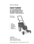
OWNER'S MANUAL
CRRFTSMRN _
3.8 Horsepower
9 Inch
EDGER/TRIMMER
MODEL NO.
536.797480
Caution:
Read and_follow all Safety
Rules and Operating
Instructions before first use
of this product.
Sears, Roebuck and Co., Hoffman Estates 60179 U.S.A.
339908
03/04/96
Table of Contents
Warranty
Safety Rules
Contents of Shipping Carton
Assembly
Operation
Maintenance
LIMITED
TWO-YEAR
2
2
2-3
4
5-7
7-11
11-12
WARRANTY
Service and Adjustments
Storage
Troubleshooting
Spanish (Espafiol)
Edger Repair Parts
Engine Repair Parts
Parts Ordering/Service
ON CRAFTSMAN
13-14
14-15
15
26-40
16-21
22-25
Beck Cover
EDGER/TRIMMER
For two years from the date of purchase, when this Craftsman Edger/Trimmer is mainrained, lubricated, and tuned up according to the operating and maintenance instructions in the owner's manual, Sears will repair, free of charge, any defect in material or
workmanship.
If this Craftsman Edger/Trimmer is used for commercial or rental purposes, this warrarity applies for only 90 days from the date of purchase.
This warranty does not cover the following:
• Expendable items which become worn during normal use, such as spark plugs, etc.
• Repairs necessary because of operator abuse or negligence, including bent crank
shafts and the failure to maintain the equipment according to the instructions contained in the owner's manual.
WARRAHT3' SERVICE IS AVAILABLE BY RETURNINGTHE
CRAFTSMAN EDGER/
TRIMMER TO THENEAREST
SEARS SERVICE CENTER/DEPARTMENT
IN THE
UNITED STATES. THIS WARRANTY APPLIES ONLY WHILE THIS PRODUCT IS IN
USE IN THE UNITED STATES.
This warranty gives you specific legal rights, and you may also have other rights which
may vary from state to state.
Sears, Roebuck and Co., D817WA, Hoffman Estates, IL 60179
Look for this symbol
point out
precautions.
A'FrENTION!!!
Becometo alert!!!
YourImportant
safety Is safety
involved.
,_
CAUTION: Always disconnect spark
plug wire and place wire where it cannot
contact spark plug to prevent accidental
starting when setting-up, transporting,
adjusting or making repairs.
IMPORTANT: Safety standards require
operator presence controls to minimize the
risk of injury. Your Edger/Trimmer is
equipped with such controls. Do not attempt
to defeat the function of the operato r
presence control under any circumstances.
BEFORE USE
• Read the owner's manual carefully. Be
thorQughly familiar with the controls and
the proper use of the edgerltrimme'r.
Know how to stop the edger/trimmer and
disengage the controls quickly.
• Do not operate the edger/trimmer without
wearing adequate outer garments. Wear
It means-s
footwear that will improve footing on
slippery surfaces.
• Keep the area of operation clear of all
persons, particularly small children and
pets.
• Thoroughly inspect the area where the
edger/trimmer is to be used and remove
all foreign objects.
FUEL SAFETY
• Handle fuel with care; it is highly flammable.
• Use an approved container.
• Check fuel supply before each use,
allowing space for expansion as the heat
of the engine and/or sun can cause fuel to
expand.
• Fill fuel tank outdoors with extreme care.
Never fill fuel tank indoors. Replace fuel
tank cap securely and wipe up spilled
fuel.
• Never remove the fuel tank cap ot add
fuel to a running or hot engine.
• Never store fuel or edger/trimmer with
fuel in the tank inside a building where
fumes may reach an open flame.
OPERATING SAFETY
• Never allow children or young teenagers
to operate the edger/trimmer. Keep them
away while it is operating. Never allow
adults to operate the edger/trimmer
without proper instruction.
• Do not operate this machine if you are
taking drugs or other medication which
can cause drowsiness or affect your
ability to operate this machine.
• Do not use this machine if you are
mentally or physically unable to operate
this machine safely.
• Always wear safety glasses or eye
shields during operation or while performing an adjustment or repair to protect
your eyes from foreign objects that may
be thrown from the edger/trimmer.
• Do not put hands or feet near or under
rotating parts.
• Exercise extreme caution when operating
on or crossing gravel drives, walks, or
roads. Stay alert for hidden hazards or
traffic.
• Exercise caution to avoid slipping or
falling.
• Never operate the edger/trimmer without
proper guards, plates, or other safety
protective devices in place.
• Never operate the edger/trimmer at high
transport speeds on slippery surfaces.
Look behind and use care when backing.
• Never allow bystanders near the edger/
trimmer.
• Keep children and pets away while
operating.
• Never operate the edger/trimmer without
good visibility or light.
• Do not run the engine indoors. The
exhaust fumes are dangerous, containing
CARBON MONOXIDE, an ODORLESS
and DEADLY GAS.
• Take all possi6ie precautions when
leaving the edger/trimmer unattended.
Stop the engine.
• Do not overload the edger/trimmer
capacity by attempting to edge too deep
at too fast a rate.
extended period.
• Never store the edger/trimmer with fuel in
the fuel tank inside a building where
ignition sources are present such as
water and space heaters, clothes dryers,
and the like. Allow the engine to cool
before storing in any enclosure.
• Keep the edger/trimmer in safe working
condition. Check all fasteners at frequent
intervals for proper tightness.
REPAIR/ADJUSTMENTS
SAFETY
• After striking a foreign object, stop the
engine (motor). Remove the wire from the
spark plug, and keep the wire away from
the plug to prevent accidental starting.
Thoroughly inspect the edger/trimmer for
any damage, and repair the damage
before restarting and operating it.
• If edger/trimmer should start to vibrate
abnormally, stop engine (motor) and
check immediately for the cause. Vibration is generally a warning of trouble.
• Stop the blade whenever you leave the
operating position. Also, disconnect the
spark plug wire before unclogging the
blades and when making any repairs,
adjustments, or inspections.
• When cleaning, repairing, or inspecting,
shut off the engine and make certain all
moving parts have stopped.
• Never attempt to make any adjustments
while the engine is running except when
specifically recommended by the manufacturer.
Z_ WARNING:
This unit is equipped with
an internal combustion engin_ and should
not be used on or near any unimproved forest-covered, brush-covered or grass-covered land unless the engine's exhaust system is equipped with a spark attester meeting applicable local or state laws (if any). If a
spark arrester is used, it should be maintained in effective working order by the operator.
In the state of California the spark arrester is
required by law (Section 4442 of the California Public Resources Coda). Other states
may have similar laws. Federal laws apply
on federal lands. A spark arrester/muffler is
available through your nearest Sears Authorized Service Center (See ENGINE REPAIR PARTS section in this manual).
A
WARNING:
The engine exhaust from
this product contains chemicals known to
the State of California to cause cancer, birth
defects or other reproductive harm.
SAFESTORAGE
• Always refer to the owner's manual
instructions for important details if the
edger/trimmer _sto be stored for an
3
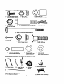
(4) - Hex Head Wide Flan_le
Screws 5/16-18x 5/8 inch
(8) - Nuts, 5/16-18
Reg Hex CtrJk
(1)- Spacer .70 inch
{left rear wheel assembly)
Illllilillll
(1) - Shoulder Bolt 3/6-16xl.400 inch
(2) - Hair Pins
3/8-16 Whiz Lock
£'!
il
%.1
I
(1) - 5/16-18 x 4.50 inch Hex Head Screw
o
1 -O._tt_ Pin
(1) - 5/16-18 Hex Head
Wide Flange Locknul
(4) - Carriage Bolts
5/16-18x 1-5/8 inch
©!
0
(2) - 1.39 Inch I°ng Spacer
(front wheel assembly)
Parts packed separately
(1) - Lower Handle
(1) - 1/2 x 3/4 inch
Flatwasher(left rear
wheel assembly)
(4) - Flatwashers
.344x.69x.065
(front wheel assembly)
in carton (not shown full size)
(1) - Upper Handle
Assembly
I - Owner's Manual (not shown)
2 - Parle Bags (not shown)
i4) - Wheels
8xl.75
1 - Container SAE30 oil
(1) - Handle Panel Assembly
A
L_ CAUTION:
Always wear safety
glasses or eye shields While assembling
edger/trimmer.
TOOLS REQUIRED
FOR ASSEMBLY
2 - 1[2 inch Wrenches
(or adjustable wrench)
2 - 9/16 inch Wrenches
(or adjustable wrenches)
2 - Adjustable Wrenches
1-
Knife
1 - Regular Screwdriver
1 - Pliers
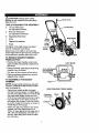
Handle
Handle
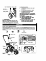
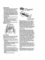
The figure to the right shows the edger/
trimmer completely assembled.
Handle
References to the right or left hand side
of the edger/trimmer are from the viewpoint
of the operator's position behind the unit.
TO REMOVE EDGER/TRIMMER
FROM CARTON
• Remove the lower handle, control rod,
upper handle and packing material from
the carton.
Lower Handle
• Remove wheels, parts bag and packing
material from the carton.
5/16-18 X 5/8 inchl_I
• Cut down all four corners of the carton.
flange Screws
hex head wide
\\ _l-_HexH ead I
• Remove packing material from around
edger/trimmer
blade.
TO ASSEMBLE
TRIMMER
THE EDGER/
NOTE: Lower handle should be attached
first as it is difficult to attach lower handle
with the wheels on.
• Place lower handle inside the edger/
trimmer frame as shown in middle figure
and secure in place with four 5/16-18x5/8
hex head wide flange screws and four
5/16-18 hex head Iocknuts found in parts
bag. Hold back on the lower handle as
you tighten the screws. Locknuts should
be on the inside'of the frame as shown in
middle figure of this page.
• Attach the right rear wheel to the wheel
support rod of the edger/trimmer as
shown in lower figure on this page with a
1/2 x 3/4 inch flatwasher and cotter pin
found in parts bag. Bend ends of cotter
pin with pliers.
Frame
_
_
VIEW FROM RIGHT REAR WHEEL
Flatwasher
1/2x3/4 inch
Wheel
control rod through the hole in the quill
support arm. Attach with hairpin found in
parts bag.
• Move the clutch lever to rearmost
• Attach the left rear wheel to the edger/
trimmer shown in figure below with a
3/8-16 x 1.40 inch Shoulder bolt, spacer
and 3/8-16 hex head whiz lock nut found
in parts bag and tighten nut.
NEUTRAL position and latch in.
VIEW FROM INSIDE LEFT REAR WHEEL
Spacer
(.70 inch long)
• If it is difficult to get the clutch lever into
NEUTRAL, it may be necessary to loosen
the four screws and nuts holding the
lower handles to the frame as shown in
first figure on page 7. Pry up (forward) on
the handles only enough to allow the
clutch lever to freely enter the NEUTRAL
position. Re-tightan nuts and screws.
When the clutch lever is in NEUTRAL the
Shouk_erBolt
3/8-16xl .40
quill support arm should be close to the
spacer and screw behind it as shown
in last figure on this page•
3/8-16
Whiz-lock Nut
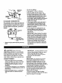
• Attach the front wheels to the Edger/
Trimmer shown in figure below with a
5/16-18 x 4.50 inch hex head screw, four
11/32 x 11/16 inch flatwashers, two
spacers and a 5/16-18 hex head wide
flange locknut found in parts bag.
VIEW FROM FRONT
._--.
,.
Flatwasher
11/32xt 1/16
'_
_
Rod
_1_ First _epth-_
_Selection
I_
Handle Panel
5/16-18xl-5/8
11/32xl
Hex Head Screw
5/16-18 Hex
5/16-18 Wide
Head Lock,
nut
Flange Locknut
Inch Long)
Handle
• Place the handle panel on the inside of
lower handle. Hold in place while placing
the upper handle on the lower handle as
shown in next figure. Align holes in upper
handle, lower handle and handle panel,
secure in place with four 5/16-18 x
1-5/8 inch carriage bolts and four
5/16-18 hex head Iocknuts found in parts
bag. Locknuts should be to the inside of
the handle panel as shown.
• The clutch lever is located on the left
hand side of upper handle when properly
installed. Insert one end of the control rod
from left to right through the hole in the
clutch lever and attach with a hair pin
found in parts bags. See figure.
* Place the clutch_lever in the first depth
selection and insert the other end of the
6
Quill
VIEWFROMRIGHTSIDEOFUNI,T
the following checklist:
,#
All assembly instructions have been
completed.
Right Side
Lower Handle
,/
No remaining loose parts in carton.
/
All fasteners have been properly
installed and tightened.
While learning how to use your edger/trimmer, pay extra attention to the following important items:
//
Engine oil is at proper level.
,#/
Fuel tank is filled with fresh, clean,
regular unleaded gasoline.
/
CHECKLIST
,//
Before you operate and enjoy your new
edger/trimmer, we wish to ensure that you
receive the best performance and satisfaction from this quality product, please review
Become familiar with the location and
function of all controls. Operate
controls before starting engine.
KNOW YOUR EDGER/TRIMMER
READ THIS OWNER'S MANUAL AND SAFETY RULES BEFORE OPERATING YOUR
EDGER/TRIMMER.
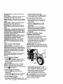
Compare the illustrations with your EDGER/TRIMMER
to familiarize
yourself with the location of various controls and adjustments. Save this manual for future
reference.
Fast
Slow
Stop
Primer Button
Control Rod
Oil Fill Cap/
Blade
Guard
Throttle
VIEW OF BLADE AREA
_'
Starter.
Handle
J
Wheel
Throttle Control - Used to control the engine speed.
Primer Button - Injects fuel directly into the
carburetor manifold for faster starts,
Starter Handle -The engine on this Edger/
Trimmer is equipped with an easy pull recoil
starter.
Clutch Lever - Used to start and stop the
blade and control the depth of cut.
Blade Guard - Used to prevent stones or
other material from being thrown at the operator.
Index Lever - Permits adjustment from the
edging (vertical) position to trimming (horizontal) position. To change position, pull the
index lever and rotate the quill assembly to
the _esired angle or position.
seconds between each push.
• Do not use primer button I._.to restart
a warm engine after a short shutdown.
TO USE THE CLUTCH
LEVER
• Start the engine and move the clutch
lever forward or down to engage the
cutting blade•
• Select the edging depth you need.
There are 5 selections up to 2-3/4
inches deep.
IMPORTANT: If very deep edging is
required, we recommend that a shallow cut be made first, then cuts at
greater depths until the desired depth
• is obtained.
TO USE THE
INDEX
LEVER
Adjustable Rear Wheel - Right rear wheel
is adjustable to level edger/trimmer when
edging along a curb(curb-hopping).
(TRIMMING
Adjustable Front Wheel - Front wheel is
adjustable fr_ side-to-side for balance.
Also, can be adjusted down for curb-hopping.
• Loosen the knob shown in figure below
on the fror_t wheel arm and slide the
wheel all the way to the right side.
HOWTO
Z_CAUTION:
USE YOUR EDGER
LL_WARNING:
The operation of this
edger/trimmer can result in foreign objects
being thrown into the eyes, which can cause
severe eye damage. Always wear safety
glasses or eye shields while operating the
edger/trimmer.
OPERATION)
• Stop engine and disconnect the spark
plug wire from the spark plug.
• Tighten the knob securely.
The front wheel must be
in the extreme right position to prevent the
blade from striking wheel while in trimming
position.
We recommend standard safety glasses or
Wide Vision Safety Mask for over your
glasses.
TO STOP EDGER/TRIMMER
• To stopO
the engine, make sure the
clutch lever is all the way back or up and
move the throttle control lever to the
STOP pesiton.
Z_
CAUTION:
Never leave the edger/
trimmer unattended while the engine is
running. Always disengage the cutting blade
and stopl_ the engine.
TO USE THROTTLE
CONTROL
• Run at full'_ engine speed during
normal use.
• Push throttle control lever up to increase
speed; down _
to decrease speed.
TO USE PRIMER BUTTON
Knob
• Pull the index lever out of its notch as
shown below and position it in the
notch marked 90 °. See figure on page 9.
• Reconnect the spark plug wire and
start the engine. Move the clutch
lever to the desired trimming height.
,Z_
CAUTION:
Never leave the edger/
trimmer unattended while the engine is
running. Always disengage the cutting
• Push primer button ]._-five times. See
_ blade and stop the engine.
page 7 figure for location. Wait about two
Z_ CAUTION:
Keep away from the
rotating blade. The blade can cause injury.
BEFORE
STARTING
ENGINE
PRE-USE CHECK OF CONTROLS
All controls should be checked for proper
function before servicing or starting the
engine.
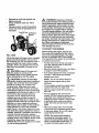
INDEX LEVER IN THE NOTCH MARKED "90"
TO USE CURB-HOPPING
• Move the clutch lever into all six
positions in the selector plate. Make
sure the clutch lever snaps into all six
holes.
FEATURE
The adjustable front and right rear wheel
feature permit the edger/trimmer to be used
on an uneven surface such as a curb as
shown in figure below.
• Return the clutch lever to the rearmost
hole in the selector plate.
FILL/ADD OIL:
Stop the engine and disconnect the
spark plug wire from the spark plug.
Loosen the knob on the front wheel arm
bracket and slide the wheel to the best
position to clear the curb and balance the
unit.
This edger/trimmer was shipped with a 20
ounce container of SAE30 motor oil. This
oil must be added to the.engine before
operating. Remove the oil fill cap-dipstick
and fill the crankcase to FULL line on
dipstick (20 ounces). Check frequently
when filling the crankcase. DO NOT
OVERFILL.
• Tighten the knob securely.
• Using the curb height adjust lever, lower
the front wheel to a position that places
the edger/trimmer level with the left rear
wheel on the uneven curb surface.
NOTE: Engine may already contain some
residual oil.
• Loosen tee knob on the inside right rear
of the main frame that secures the wheel
support rod as shown below.
• Slide the rear wheel down until the
edger/trimmer is level when the left
wheel is on the curb.
Tighten the fill cap-dipstick securely each
time you check the oil level.
OIL RECOMMENDATIONS
Only use high quality detergent oil rated
with API service classification SG. Select
the oil's SAE viscosity grade according to
your expected operating temperature.
• Tighten the knob securely.
= Reconnect the spark plug wire and start
the engine. The depth of cut adjustment
is the same as described in Edging
Operation paragraph.
Although multi-viscosity oils (5W30, 1OW30,
etc.) improve starting in cold weather, these
multi-viscosity oils will result in increased oil
consumption when used above 32°F.
Check your engine oil level more frequently
to avoid possible engine damage from
running low on oil.
<<
I Colder <<
5W30
Front Wheel Arm
TO ADD ENGINE OIL
(Behind_.
Wheel) \
• Place the edger/trimmer on a level
surface.
• Remove the oil fill cap-dipstick as shown
in figure on page 10.
• Fill the engine crankcase, pouring slowly.
Do not overfill. For approximate capacity
see PRODUCT SPECIFICATIONS
chart
in this manual.
Rear
Support
Rod
Wheel
Adjust Lever
9
•
•
•
Reinstall the oil fill cap-dipstick and
tighten securely.
Check oil before each use. Add if
needed.
Change oil after the first 2 operating
hours and every 25 operating hours
thereafter.
Fuel Fill Cap Oil Fill Cap-
Z_
WARNING:
Experience
indicates
that alcohol blended fuels called gasohol or
using methanol can attract moisture which
leads to separation and formation of acids
during storage. Acidic gas can damage the
fuel system of an engine while in storage.
To avoid engine problems, the fuel system
should be emptied before storage of 30
days or longer. Drain fuel tank, start engine
and let it run until fuel lines and carburetor
are empty. Use fresh fuel next season. See
Storage Instructions for additional information. Never use engine or carburetor
cleaner products in the fuel tank or permanent damage may occur.
TO START THE ENGINE
Before starting the engine, be sure you
have read and understood all the instructions on the preceding pages. The edger/
trimmer is equipped with a recoil starter.
The operation of the engine is controlled by
the throttle control lever.
FILL GAS
Fill the fuel tank with clean, fresh, unleaded
grade automotive gasoline. Be sure that
the container you pour the gasoline from is
clean and frOe'from dust or other foreign
particles. Never use gasoline that may be
stale from long periods of storage in the
,_ainer.
• Pull the clutch lever all the way back or
up to the rearmost hole to raise and
disengage the blade.
• Move the throttle control lever, see figure
on page 7 to the FAST position.
CAUTION:
Never fill the gas tank
while the engine is running or hot.
Immediately wipe off any spilled gasoline
before attempting to start the engine.
,Z_
CAUTION:
• Push primer button five times, see figure
on page 7. Wait about two seconds
between each push.
Gasoline is flammable
NOTE: Do not use primer button to
restart a warm engine after a short
shutdown.
and caution must be used when handling or
storing it. Do not fill fuel tank while edger/
trimmer is running, hot, or when in an
enclosed area. Keep away from open
flame, electrical spark, and do not smoke
while filling the fuel tank. Never fill fuel tank
completely; but fill the tank to within 1/4-1/2
inch from the top to provide space for
expansion of fuel. Always fill fuel tank
outdoors and use a funnel or spout to
prevent spilling. Make sure to wipe up any
spilJed fuel before starting the engine. Store
gasoline in a clean, approved container,
and keep the cap in place on the container.
Keep gasoline in a cool, well ventilated
place; never in the house. Never buy more
than a 30 day supply of gasoline to assure
volatility. Gasoline is intended to be used as
a fuel for internal combustion engines
therefore, do not use gasoline for any other
purpose, Since many children like the smell
of gasoline, keep it out of their reach
because the fumes are dangerous to inhale,
as well as being explosive.
To start engine, grasp the engine starter
handle firmly with your right hand.
" Hold the edger handle firmly with your
left hand.
° Pull up sharply on the recoil stader
handle. DO NOT allow the starter rope to
snap back, let it rewind slowly while
holding the starter handle. If engine fails
to start after three pulls, push primer
button two times and pull starter rope
again.
When the engine starts. Push throttle
control lever up to increase speed; down
to decrease speed. Run at full engine
speed during normal use.
NOTE: The cutting blade speed is
controlled by the engine speed. To
reduce the cutting blade speed, push
down on the throttle control lever. To
increase the blade speed, push the
tO
throttle control lever up.
• If very deep edging is required, we
recommend that a shallow cut be made
first, then cuts at greater depth until the
desired depth is obtained.
• To stop the engine, make sure the clutch
lever is all the way back or up and move
the throttle control lever to the STOP
IO
Z_
• Uniform edging can be performed when
the blade guide rides on and against the
surface which you are edging.
position.
CAUTION:
Never run the engine
indoors or in a poorly ventilated area.
Engine exhaust contains carbon monoxide,
an odorless and deadly gas. Keep hands,
feet, hair and loose clothing away from any
moving parts on the engine or edgerl
trimmer. Avoid the muffler and surrounding
areas. Temperatures may exceed 150 ° F.
• Edging can be customized by varying the
number of passes and by the distance
your blade is from the surface you are
edging.
PRODUCT
SPECIFICATIONS
Horse Power:
3.8
Displacement:
9.52 cu. in. (156 cc)
Gasoline Capacity:
2.0 qt. (unleaded)
Lubrication:
20 oz. SAE-30W
Spark Plug:
Champion CJ-8 or
Equivalent
EDGING TIPS
• Edging is best performed when conditions
are dry. If the soil is to wet, dirt becomes
packed in and around the blade causing
premature belt wear and decreased
performance.
• If dirt does become packed around the
blade, stop the engine, remove the spark
plug wire, and remove the packed debris
before continuing to edge.
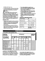
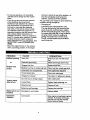
CUSTOMER
RESPONSIBILITIES
SCHEDULE
Fill In
dates as
you
complete
regular service
After
Before
FrsEvery
Begin Storage
Before
First
Each
qusntly E_ary Every
10
25
Each
2
use
Hours Hours Houn Season
Hours
Lubricateall Pivot Points
p,t
Lubricate Wheel Axles
_vj
Check Engine Oil Level
Change EngineOil
SERVICE
DATES
p_,
p_'
_
Replace Air Cleaner Filter
p_'
Check Spark Plug
Check Drive Bell .
_
p,4
V"
,1
Tighten All Screws and Nuts
p_
Check Blade Wear/Damage
GENERAL
p_
RECOMMENDATIONS
must maintain the edger/trimmer as instructed in this manual. The above chart is
provided to assist the operator in properly
maintaining the edger/trimmer.
The warranty on this edger/trimmer does
not cover items that have been subjected to
operator abuse or negligence. To receive
full value from the warranty, the operator
11
i
LUBRICATION
• After each 25 hours of use of your edger/
trimmer, apply light machine oil to all
moving parts, particularly the wheels.
_
f
_,
• The oil in the engine crankcase must be
changed after the first 2 hours of operation and after each 25 hours of use thereafter. See OIL RECOMMENDATIONS
in
OPERATIONAL sectional in this manual.
• Flange
TO CHANGE OIL
Slot
(counterclockwise)
urn cover to the left
toremove
Tab
• Disconnect the spark plug wire from the
spark plug.
• Remove the oil drain plug as shown below and drain the oil into a fiat pan.
Turn cover to the right
(clockwise)ot install
• After draining all the oil, reinstall the oil
drain plug securely.
NOTE: The oil will drain more freely when
the engine is warm.
Z_ CAUTION:
Never run the engine
without the air cleaner element installed. A
defective air cleaner can result in loss of
engine power and can cause excessive
wear or damage to the engine components
'
if dirt or dust is permitted to enter the
engine through the carburetor. A damaged
air cleaner, or one that is clogged with dust
or dirt should be replaced immediately.
VIEW FROM REAR
SPARK PLUG
Clean the spark plug and reset the gap
periodically. Before removing spark plug,
clean the area around its base to prevent
dirt from entering into the engine. Replace
the spark plug if the electrodes are pitted or
burned or if the porcelain is cracked. Clean
the spark plug by carefully scraping the
electrodes with a knife or screwdriver (do
not sand blast or use a wire brush). Be sure
the spark plug is clean and free of foreign
material. Check the electrodes gap with a
wire feeler gauge and reset to .030 if
necessary. If a new spark plug is needed,
refer to the Engine manual for the proper
replacement spark plug.
Plug
AIR CLEANER
Replace the filter once a year; more often
under dusty or dirty conditions, DO NOT
attempt to clean or oil the air filter.
To install a new air filter, do the following:
• Disconnect the spark plug wire from the
spark plug.
• Turn the cover as shown below to the left
counterclockwise and remove the cover
and the air filter from the flange.
• Discard the air filter.
Before reinstalling the spark plug, coat the
threads lightly with graphite or light oil to
insure easy removal. Tighten the spark plug
firmly into the engine. If a torque wrench is
available, torque the spark plug to 15 footpounds.
• Clean the cover and the flange thoroughly.
• Insert the new air filter into the cover.
//_
CAUTION:
Always stop the engine
and disconnect the spark plug wire before
making any repairs to the edger/trimmer.
• Push the cover firmly against the flange
and turn it to the right clockwise as far as
it Will go as shown in figure below. Be
sure the retainers are locked around the
flange.
• Reconnect the spark plug wire.
12
V-BELT
REPLACEMENT"
Your edger/trimmer is equipped with a
V-belt made of a special compound. If the
belt becomes worn or breaks replace it with
an orignal equipment bell as shown in the
Repair Parts section of this manual. Never
use a substitute.
• Disconnect the spark plug wire.
• Put the clutch lever back or up to release
the tension from the bell.
Belt
• Remove the two top screws from the
engine pulley cover as shown in figure
below and remove the cover. Make sure
Belt,
Screws
you do not lose the spacer on the rear
BLADE
screw,
REPLACEMENT
The cutting blade is subject to wear and
damage such as nicks and dents. This will
not generally affect its function.
This blade is specially designed to not require sharpening. Do not attempt to sharpen
this blade. The blade is reversible. If the
nicks and dents are excessive, remove the
blade, turn it around and reinstall. This will
provide a fresh cutting edge. The blades
should be replaced if both sides are worn
and damaged.
Screw
Z_
CAUTION:
When removing or tightening the blade nut, always use the method
shown in figure on next page. The holding
wrench must always be positioned on the
nut behind the cutting blade.
Rear
Guide Screw
• Remove the front screw securing the belt
guide as shown above to the engine.
Then loosen the rear screw and swing the
belt guide away from the belt.
• Remove the three screws from the belt
guard as shown in next figure.
Z_
CAUTION:
Do not attempt to sharpen
this blade. Sharpening could,damage it and
cause it to break, which may further result in
injury to yourself or a bystander.
To replace the blade, do the following:
• Remove the belt from the engine and quill
assembly pulleys and install the new belt.
• Disconnect spark plug wire.
• Remove the 1/2-20 Iocknut shown in next
figure securing the blade to the drive
shaft.
• Install and secure front belt guard.
• Secure the belt guide loosened earlier.
• Remove the blade.
• Reinstall the engine pulley cover and
reconnect the spark plug wire.
• Install the new blade and reinstall nut.
Tighten the nut securely.
• Reconnect the spark plug wire.
13
• Do not over-tighten.
• Then open it 1-1/4 to 1-1/2 turns.
• Start the engine and let it warm up.
_Locknut
TO ADJUST
• Set the throttle control to FAST. Adjust
the high speed adjusting screw In until
the engine speed or sound alters. Adjust
the,screw out until the engine speed
sound alters. Note the difference between
the two limits and set the screw in the
middle of the range.
CARBURETOR
The carburetor shown below has been preset at the factory and readjustment should
not be necessary. However, if the carburetor does need to be adjusted, proceed as
follows:
_
• If the engine tends to stall under load or
not accelerate from low speed to high
speed properly, adjust the high speed
screw out in 1/8 turn increments until the
problem is resolved.
• Let the engine run undisturbed for 30
seconds between each setting to allow
the engine to react to the previous
adjustments,
Carburetor
IMPORTANT:
Never tamper the engine
governor, which is factory set for proper
engine speed. Overspeeding the engine
above the factory high speed setting can
be dangerous. If you think the enginegoverned high speed needs adjusting,
contact your nearest Sears Service
Center, which as the proper equipment
and experience to make any necessary
adjustments.
....
High Speed
. I_J
AdjustingScrew
"- _"='_-'-'_(C
ose finger tght
only)
• Close the high speed adjusting screw by
hand.
L_
CAUTION:
Never store your
IMPORTANT:
edger/trimmer indoors or in an enclosed,
poorly ventilated area Jfgasoline remains
in the tank fumes may reach an open
flame, spark or pilot light from a furnace,
water heater, clothes dryer, cigarette, etc.
A yearly checkup or tune-
up by a Sears Service Center is a good
way of ensuring that your edger/
trimmer will provide maximum performance for the next season.
ENGINE
EDGER/TRIMMER
IMPORTANT:
It is important to prevent
prevent gum deposits from forming in
essential fuel system parts such as the
carburetor, fuel filter, fuel hose, or tank
during storage. Also, experience indicates
that alcohol-blended fuels called gaschol or
using ethanol or methanol can attract
moisture which leads to separation and
formation of acids during storage. Acidic
gas can damage the fuel system of an
engine while in storage.
• Clean the edger/trimmer thoroughly;
remove all debris and wipe the unit dry.
• Inspect the edger/trimmer for worn or
damaged parts and tighten all loose
hardware.
• Oil all points described in the Lubrication
paragraph in the Maintenance section of
this, manual.
• Store the edge/trimmer in a protected
area and cover for additional protection.
To prevent engine damage (if edger/
trimmer is not used for more than 30 days)
follow the steps on next page.
14
i
• To remove gasoline, run the engine
until the tank is empty and the engine
stops.
trimmer is stored in any other position,
from the crankcase could enter the
oil
cylinder, causing a service problem.
• If you do not want to remove gasoline
a fuel stabilizer (such as Sears
Craftsman fuel stabilizer No. 33500)
may be added to any gasoline left in
the tank to minimize gum deposits
and acids. If the tank is almost empty,
mix stabilizer with fresh gasoline in a
separate container and add some to the
tank. Always follow instructions on
stabilizer container. Then run engine at
least 10 minutes after stabilizer is added
to allow mixture to reach carburetor.
You can keep your engine in good operating
condition during storage by:
• Changing oil.
• Lubricating the piston/cylinder area.
This can be done by first removing the
spark plug and squirting clean engine
oil into the spark plug hole. Then cover
the spark plug hole with a rag to absorb
oil spray. Next, rotate the engine by
pulling the starter two or three times.
Finally, reinstall spark plug and attach
spark plug wire.
Store edger/trimmer
in a safe place. See
IMPORTANT under STORAGE (ENGINE).
• Store the edger/trimmer in the wheelsdown, operating position. If the edger/
TROUBLE
Difficult starting
CAUSE
CORRECTION
Stale fuel
Drain fuel tank. Fill with fresh
fuel
Defective spark plug
Clean and re-gap spark plug
Clogged fuel line
Replace fuel filter
Blocked fuel line or empty fuel tank
Clean fuel line; check gas tank
Carburetor out of adjustment
Have carburetor adjusted
Fouled spark plug
Clean and adjust gap
Clogged air cleaner
Tap clean or replace air cleaner
Jammed due to foreign object
Clear obstruction
Loose blade
Tighten blade retaining nut
Defective belt
Replace V-belt
Defective quill bearings
Replace the bearings
Blade fails to cut
properly
Damaged or worn blade
Replace blade
Excessive
vibration
Loose parts
Stop engine immediately; tighte_
all bolts. If vibration continues,
take the unit into the nearest
Sears Service Center
or
Engine runs
erratic
Cutting blade
fails to turn
15
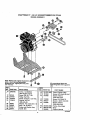
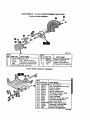
CRAFTSMAN
9" - 3.8 H.P. EDGER/TRIMMER
ENGINE ASSEMBLY
Note: Nways use original equipment €
parts. Use of sewice/replacement
partsothar than odginal parts may void
your warranty.
REF. !
NO. PART NO.
.10
ENGINE
12
20
22
24
48148
314781
181608
120638
26
29
30
32
456O2
32668
313011
51600
536.797480
All unnumbered items ere
interchangeable with opposite
side
REF.
NO. PART NO.
PART NAME
3.8 hp. 143.963509
(See Enginepages)
Screw, 3/8-16 x 1.00
Pulley, Half V3L
Screw, 5/16-24x 1.00 HHC
Washer, SPTL_
.328x.60x.09
Washer, Flat .333x.87x.119
Belt, V 4L 32.60LG
: Screw and Washer Ass]/
Guide, Belt
40
41
42
331281-848
181624
315095
43
44
45
173030
308237
315095
80
81
323534-848
308154-848
339908
PART NAME
Cover, Engine Pulley
Screw, 5/16-24x3.00 HHC
Spacer, Sleeve
.335x.431x2.50
Screw, 5/16-24x3.75
Spacer, .3221D .562 OD
Spacer, Sleeve
.335x.431x2,50
Frame, Assy Edger
Strap
Owner'sManual
323095D
16
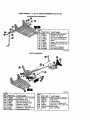
CRAFTSMAN
9" - 3.8 H.P. EDGER/TRIMMER
BLADE GUARD ASSEMBLY
536.797480
O
O
O
332247 D
! REF.
NO. PART NO.
REF.
NO. PART NO.
PART NAME
1
2
3
4
5
Blade Guard
Cart. Bolt 5/16-18x.63
Flatwasher .344x.69x.065
Nut, 5/16-18 Reghexctrlk
Guide, Bert Front
331076-848
57072
120393
1498
326748-848
6
8
9
10
995346
53405-848
411666
_5Ol
PART NAME
Screw, 1/4-20x.50 Tap
Cover, Quil| Pultey
Screw, 10-24x.50 Tap
Flatwasher .203x.56x.040
FRONT WHEEL BRACKET ASSEMBLY
REF
NO. PART NO.
PART NAME
150 339299-848
151 331422
152 338614
153 325892
154 331421
155 332002
156 331419
157 20252
158 22265
159 45905
160 51333
161 331394-84_
162 I 120393
163 339388
164
1498
Arm, Front Wheel
Rod, Front Mount Curb Hopper
Pushnut,Washer
Washer, Plastic
Spacer, Height Adjust
Pin, Spring .187Diax1.50Lg
Lever, Height Adjust
Knob, Rectangle
Flatwasher .515x 1.38x. 119PL
Nut, 3/8-16 Hwdfllk Mack
Screw. 5/16-18x.63
Plate, Height Adjust Quad
Flatwasher, .344x.69x.065
Knob,W/5/16-18 Stud
Nut, 5/16-18 Reghexctr_
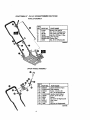
CRAFTSMAN
9" - 3.8 H.P. EDGER/TRIMMER
536.797480
CURB HOPPER ASSEMBLY
REF.
NO.
L17o
171
172
18o
181
182
183
184
185
186
PART NO.
6842
18oo77
1498
126380
8082
45222
12o393
13527
t 20376
310896
PART NAME
Bracket, Curb Hop Mnt
Screw, 5/16- t 8x.75
Nut, 5/16-18 Reghexctrlk
Cart. Bolt, 5/16-18x2.00
Clevis
Spacer, Slev .356x.63x1.01
Flatwasher .344x.69x.065
Knob, T
Nut, 5/16-18 Reghex
Rod, Wheel Support
323179D
BLADE ASSEMBLY
323129C
REF
NO.
3OO
301
302
305
310
311
312
320
PART NO.
120396
338656-848
308254
1499
308243
411666
1501
51603
REF.
NO.
321
322
323
325
329
330
331
PART NAME
Flatwasher, .53lx 1.06x.095
Quill Suppt. Assy.
Shoulder Bolt3/8-16
Nut, 3/8-16 Reghexctdk
Deflector,Rubber
Screw, 10-16x.50 Tap
Flatwasher, .203x.56x.040
CompressionStodng
_8
PART NO.
338070
308466
308155
1498
22265
334056-853
46023
PART NAME
Quill Assembly, LrgSuppt.
Index Lever
Torsion Spring
Nut, 5/16-18 Reghexctrlk
Flatwasher, .515x1.38x. 119
Blade Edger
Nut, 1/-20 Wdfl
CRAFTSMAN
9" -:_.8 H.P. EDGER/TRIMMER
536.797480
HANDLE ASSEMBLY
REF.
'NO. PART NO.
I1
2
3
4
5
7
8
51333
1498
56199
36368
332232-853
580292-853
1498
PART NAME
Screw, 5/16-18x.63
Nut, 5/16-18 Reghexctrlk
CarT.Bolt, 5/16-18xl .63
Hair Pin .072Diax1.13Lg
Lower Handle
Control Rod
Nut, 5/16-18 Rehexctrlk
_2_7C
\
UPPER HANDLE ASSEMBLY
°7
REF.
NO. PART NO.
725 332239
731 310052-85_
732 180024
735 1502
737 310050-85_
738 180081
739 25644
740 1498
741 307017
743 ! 310053
745 1499
PART NAME
Upper Handle & Foam
Plate Selector
Screw, 1/4-2Oxl .25
Nut, 1/4-20 Reghexctrlk
Handle, Depth Adjust
Screw, 5/16-18xl.25
Spring
Nut, 5/16-18 Reghexctrlk
Grip, Hand
Stud
Nut, 3/8-16 Reghexctdk
323136E
19
CRAFTSMAN
9" - 3.8 H.P. EDGER 536.797480
TIRE ASSEMBLY
REF.
NO.
650
651
653
654
655
667
668
669
670
680
PART NO.
336556
55273
190628
120393
51887
310716
1310715
45171
2968
121222
PART NAME
Tire & Rim w/Brg 8xl .75
Nut, 5/16-18 Wdflik
Screw, 5/16-18x4.50
Flatwasher, .344x.69x.065
Spacer, Slev .328x.495x1.39
Shoulder Bolt, 3/8-16
Spacer, Slev .390x.70x.70
Nut, 3/6-16 Whiz-lock
Flatwasher .504x.75x,059
Cotter Pin .090Diax.75Lg
332244B
@
@
@
HANDLE PANEL ASSEMBLY
REF,
NO. / PART NO.
PART NAME
760 I 331697-853 Handle Panel Assembly
332228B
2O
CRAFTSMAN
9" - 3.8 H.P. EDGER 536397480
DECALS
REF.
NO.
820
821
822
823
824
825
826
829
PART NO,
339122
69711
338983
402881
312548
402871
338979
PART NAME
Decal, Recoil Cover
Decal, Informalion Danger
Reference Only
Decal, 3.8 Sears Edger
Decal, Angle Indicator
Decal, Quadrant Selector
Decal, Blade Guard
Decal, Panel Sears
332240C
21
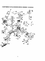
CRAFTSMAN 4-CYCLE ENGINE MODEL NUMBER: 143.963509
22
CRAFTSMAN
4-CYCLE ENGINE MODEL NUMBER: 143.963509
REF.
NO.
PART NO.
1
36591
2
14
15
16
17
18
19
2O
25
26727
28277
31334
31336
31335
350548
34593
3260O
36552
25A
26
26A
30
40
40
35883
350802
550926
35902
34614
34515
40
34516
41
32538B
41
32548B
4t
32549B
42
42
42
43
45
28986
28987
28988
20381
3O963B
46
48
49
5O
6O
65
69
70
32610A
27241
28594
33149A
29745
650128
27677A
34683A
72
75
8O
81
82
27642
26208
30574A
3059OA
30591
83
86
89
9O
92
93
100
102
103
6O588A
650488
610961
611195
850815
650816
34443A
650872
651007
110
119
120
125
35182
36437
36438
36471
125
36472
126
29314B
126
29315C
130
130A
650694
6021A
REF.
NO.
PART NAME
Cylinder
(incL 2, 20, 72, & 125)
Dowel
Washer
Governor Rod
Governor Lever
GovernorLeverClamp
Screw, 8-32 x 5/16"
ExtensionSpring
Oil Seal
Blower HsingBaffle
(incl. 262)
BaffleExtension
Scrow, 1/4-20 x 5/8"
Screw, 8-32 x 21164"
Crankshaft
Piston,Pin& Ring Set
Piston,Pin& Ring Set
(0.010 OS)
Piston,Pin& Ring Set
(0.020OS)
Piston& Ring Assy
(Std) (Inc143)
Piston& Pin Assy
(.010" OS) Inc143
PisTon& Pin Assy
(.02O"OS (inc143)
Ring Set (Std)
Ring Set (.010" OS)
Ring Set (.O2O"OS)
PistonPin Retain Ring
ConnectingRod Assy
(inc146 & 49)
ConnectingRod Boll
Valve Lifter
Oil Dipper
Camshaft (BCR)
BlowerHousingExt.
Screw, 10-24 x 1/2Cylinder Cover Gasket
Cylinder Cover (Inc175
Inru 83)
Oil Drain Plug
Oil Seal
Governor Shaft
Washer
Governor Gear Assy
(Inc181)
Governor Spool
Screw 1/4-20 x 1-1/4"
Flywheel Key
Flywheel
BellavilleWasher
Rywheel Nut
SoLidState Ignition
Solid State MflngStud
Screw. TorxT-15, 10-24
x 15/16"
o" Ground Wire
Cylinder Head Gasket
Cylinder Head (inc1130)
Exhaust Valve (Std)
(Inc1.151)
Exhaust Valve (1/32" OS)
(Inc1151)
Intake Valve (Std)
(inc1151}
Intake Valve (1/32" OS)
(inc1151)
Screw 5/16-18 x 2"
Screw 5/16-18 x 1-112"
PART NO.
650708
33636
31672
31673
27234A
27666
31410
34146
35350
3O2OO
29752
3O593
6201
26756
36703
31341
36677
31342
650549
610973
650139
30322
32410
650451
26754A
650932
34338
35797
35066
35O65
35585
650737
36493
650988
36487A
650926
29774
2646O
650665
35591
35335
35554
35499
35539
35556
34080
28212
35926
650751
32664
36261
35703
36695
632589
590732
36439
36O85
650760
PART NAME
Washer
Resistor Spark Plug
(CJ8)
Valve Spring
Valve SpringCap
Valve Cover Gasket
Breather Body
Breather Element
Valve Cover
Breather Tube
Screw 10-24 x 9116"
Nut & Lock Washer
1/4.28
Retainer Clip
Screw 114-28 x 7/8"
Carburetorto intake
Pipe Gasket
Intake Pipe
(Ind 182, 184,224)
Governor Link
ControlBracket(Incl.
203 thru 209A)
CompressionSpring
Screw 5-40 x 7/16"
TerminaJ
Screw 8-32 x 1/2"
Locknut,8-32
ControlKnob
Screw 114-20 x 1"
Intake Pipe Gasket
Screw 10-32 x 4g/64"
Air Cleaner Gasket
Air Cleaner Collar
Air Cleaner Filter
Air Cleaner Cover
BlowerHousing
Screw 1/4-20 x 1,2"
Muffler (Inc1277)
Screw 114-20x 2-5/16"
Starter Cup
Screw 8-32 x 21/64"
Fuel Line
Fuel LineClamp
Screw 114-15K 7/8'
Fuel Tank
(Inc1292 & 301)
Fuel Cap
Oil Fill Tube
"O" Ring
FillTube Clip
Dipstick
Spacer
Spacer
Fuel Tank Bracket
Screw 1/4-20 x 7/16"
BaffleHeat
LubricationDecal
ControlDecal
Starter Decal
Carburetor(Inc1184)
RewindStarter
Gasket Set
SparkArrestorKit (ind
417)(opt)
Screw, 8-32x3/8" (opt)
s enginecouldhavebeen builtwith590738
slader.Referto the designol the ropepulley
strengthdbs forpart identification.
Individualstarte
i partsdo not interchange'
23
I
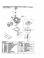
CRAFTSMAN
4-CYCLE ENGINE MODEL NUMBER: 143.963509
Carburetor No,632589
I
I
i
7
6
/
I
®
j _-
/I
I
'--"
REF. PART
NO.
NO.
632589
1•
2
4
5
6
631615
631767
631184
631183
632590
6 ' 632164
650506
25
631867
27
631024
28
632019
29
631028
30
631021
°
REF. PART
PART NAME
Carburetor
(_l_d. 184 of Engine Parts List
rottle Shaft & Lever Ass'y.
Throttle Return Spring
Dust Seal Washer
Dust Seal (Throttle)
ThrotterShutter
Shutter Screw
Fuel Fitting
Float Bowl
FloatShaft
Float
Float Bowl"O" Ring
inlet Needle, Seat, Clip
(in¢l31)
24
NO.
31
35
35A
40
41
N° .
631022
36045
632647
632591
630740
42
630739
43
630738
44
46
60
27110
631027
632592
PART NAME
SpringCip
Primer Bulb/RetainerRing
Primer Bulb Filter
Main Adj. Screw Ass]_
High Speed Mixture_Screw
"O" Ring
High Speed Mixture Screw
Washer
High Speed Mixture Screw
Tension Spring
BowlNut Washer
WelchPlugAlmosphericVenl
Repair Ki|
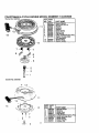
CRAFTSMAN
4-CYCLE EN(_INE MODEL
lUMBER:
143.963509
REF_ PART
PART NAME
NO. NO.
590372
Rewind Starter
1
590599,_ Spring Pin (Incl.4)
590600
Washer
1;2
3
590696
Retainer
4
590601
Washer
5
590697
Brake Spring
6
590698
Starter Dog
7
590699
Do_ Spring
8
590700
_ugey & Rewind Sprg Assy
11 590695
Starter HousingAssy
(40" grommet)
12 590535
Starter Rope
13 590701
Starter Handle
Starter No. 590732
13
Starter No. 590738
]1
•
)k
,
,"
t,___i.._
r
,..
s"
REF. PART
NO, NO.
590738
3
590740
6
590616
7
590617
5
590618h
11 590687A
12 590535
13 590701
14 590741
8
.f.-
m =
7
s_
:
I
"1
25
PART NAME
Rewind Starter
Retainer
Starter Dog
DOg Spring
Pulley&RewindSpring Ass_
Starter Housing Assy
Starter Rope
Starter Handle
LockingTab
For t_e repair or replacement parts you
need delivered directly to your home
Call 7 am-7 pm, 7 days a week
1-800-366-PART
(1-800-366-7278)
Para ordenar piezas con entrega
a domicilio -1-800-659-7084
For in-house major brand repair service
Call 24 hours a day, 7 days a week
1-800-4-REPAIR
(1-800-473-7247)
Para.pedir servicio de reparacion a
domicilio - 1-800-676-5811
For the location of a Sears Parts and
Repair Cdnter in your area
Call 24 hours a day, 7 days a week
1-800-488-1222
i1[][]ll
For information on purchasing a Sears
Maintenance Agreement or to inquire
about an existing Agreement
Call 9 am -5pm, Monday-Saturday
1-800-827-6655
When requesting service or ordering
parts, always provide the following
information:
• _roduct
Type
• Part Number
• Model Number
• Part Description
8!/ 8
Am_ca's
R_ir Spedalists
Printed in U.S.A.