1
SERVICE STATION MANUAL
854146
SL 750 SHIVER
SERVICE STATION
MANUAL
SL 750 SHIVER
THE VALUE OF SERVICE
Thanks to continuous technical updates and specific training programs on aprilia products, only aprilia
Official Network mechanics know this vehicle fully and have the special tools necessary to carry out
maintenance and repair operations correctly.
The reliability of the vehicle also depends on its mechanical conditions. Checking the vehicle before
riding, its regular maintenance and the use of Original aprilia Spare Parts only are essential factors!
For information about the nearest Official Dealer and/or Service Centre, consult the Yellow Pages or
search directly on the inset map in our Official Website:
www.aprilia.com
Only aprilia Original Spare Parts ensure products already studied and tested during the vehicle design
stage. All aprilia Original Spare Parts undergo quality control procedures to guarantee full reliability and
duration.
The descriptions and illustrations given in this publication are not binding; While the basic characteristics
as described and illustrated in this manual remain unchanged, aprilia reserves the right, at any time and
without being required to update this publication beforehand, to make any changes to components, parts
or accessories, which it considers necessary to improve the product or which are required for
manufacturing or construction reasons.
Not all versions shown in this publication are available in all countries. The availability of individual
versions should be confirmed with the official aprilia sales network.
© Copyright 2007- aprilia. All rights reserved. Reproduction of this publication in whole or in part is
prohibited. aprilia - After sales service.
aprilia trademark is property of Piaggio & C. S.p.A.
SERVICE STATION MANUAL
SL 750 SHIVER
NOTE Provides key information to make the procedure easier to understand and carry out.
CAUTION Refers to specific procedures to carry out for preventing damages to the vehicle.
WARNING Refers to specific procedures to carry out to prevent injuries to the repairer.
Personal safety Failure to completely observe these instructions will result in serious risk of personal
injury.
Safeguarding the environment Sections marked with this symbol indicate the correct use of the vehicle
to prevent damaging the environment.
Vehicle intactness The incomplete or non-observance of these regulations leads to the risk of serious
damage to the vehicle and sometimes even the invalidity of the guarantee.
INDEX OF TOPICS
CHARACTERISTICS
CHAR
SPECIAL TOOLS
S-TOOLS
MAINTENANCE
MAIN
TROUBLESHOOTING
TROUBL
ELECTRICAL SYSTEM
ELE SYS
ENGINE FROM VEHICLE
ENG VE
ENGINE
POWER SUPPLY
ENG
P SUPP
SUSPENSIONS
SUSP
CHASSIS
CHAS
BRAKING SYSTEM
BRAK SYS
CLUTCH SYSTEM
CLU SYS
COOLING SYSTEM
COOL SYS
BODYWORK
BODYW
INDEX OF TOPICS
CHARACTERISTICS
CHAR
Characteristics
SL 750 SHIVER
Rules
Safety rules
Carbon monoxide
If you need to keep the engine running in order to carry out any procedure, please ensure that you do
so in an open or very well ventilated area. Never let the engine run in an enclosed area. If you do work
in an enclosed area, make sure to use a smoke-extraction system.
CAUTION
EXHAUST EMISSIONS CONTAIN CARBON MONOXIDE, A POISONOUS GAS WHICH CAN CAUSE
LOSS OF CONSCIOUSNESS AND EVEN DEATH.
Fuel
CAUTION
FUEL USED TO POWER INTERNAL COMBUSTION ENGINES IS HIGHLY FLAMMABLE AND CAN
BECOME EXPLOSIVE UNDER SPECIFIC CONDITIONS. IT IS THEREFORE RECOMMENDED TO
CARRY OUT REFUELLING AND MAINTENANCE PROCEDURES IN A VENTILATED AREA WITH
THE ENGINE SWITCHED OFF. DO NOT SMOKE DURING REFUELLING AND NEAR FUEL VAPOURS, AVOIDING ANY CONTACT WITH NAKED FLAMES, SPARKS OR OTHER SOURCES
WHICH MAY CAUSE THEM TO IGNITE OR EXPLODE.
DO NOT DISPERSE FUEL IN THE ENVIRONMENT.
KEEP OUT OF THE REACH OF CHILDREN
Hot components
The engine and the exhaust system components get very hot and remain in this condition for a certain
time interval after the engine has been shut off. Before handling these components, make sure that you
are wearing insulating gloves or wait until the engine and the exhaust system have cooled down.
Coolant
The coolant contains ethylene glycol which, under certain conditions, can become flammable.
When it burns, ethylene glycol produces an invisible flame which however can cause burns.
CAUTION
PAY ATTENTION NOT TO POUR COOLANT ON HOT ENGINE OR EXHAUST SYSTEM COMPONENTS; IT MAY CATCH FIRE PRODUCING INVISIBLE FLAMES. IT IS ADVISABLE TO WEAR
LATEX GLOVES WHEN SERVICING THE VEHICLE. EVEN IF IT IS TOXIC, THE COOLANT HAS A
SWEET FLAVOUR WHICH MAKES IT VERY ATTRACTIVE TO ANIMALS. NEVER LEAVE THE
COOLANT IN OPEN CONTAINERS IN AREAS ACCESSIBLE TO ANIMALS AS THEY MAY DRINK
IT.
CHAR - 2
SL 750 SHIVER
Characteristics
KEEP OUT OF THE REACH OF CHILDREN
DO NOT REMOVE THE RADIATOR CAP WHEN THE ENGINE IS STILL HOT. THE COOLANT IS
UNDER PRESSURE AND MAY CAUSE BURNS.
Used engine oil and transmission oil
CAUTION
IT IS ADVISABLE TO WEAR LATEX GLOVES WHEN SERVICING THE VEHICLE.
ENGINE OR TRANSMISSION OIL MAY CAUSE SERIOUS INJURIES TO THE SKIN IF HANDLED
FOR PROLONGED PERIODS OF TIME AND ON A REGULAR BASIS.
WASH YOUR HANDS CAREFULLY AFTER HANDLING OIL.
HAND THE OIL OVER TO OR HAVE IT COLLECTED BY THE NEAREST USED OIL RECYCLING
COMPANY OR THE SUPPLIER.
DO NOT DISPOSE OF OIL IN THE ENVIRONMENT
KEEP OUT OF THE REACH OF CHILDREN
Brake and clutch fluid
THE BRAKE AND CLUTCH FLUIDS CAN DAMAGE THE PLASTIC OR RUBBER PAINTED SURFACES. WHEN SERVICING THE BRAKING SYSTEM OR THE CLUTCH SYSTEM PROTECT
THESE COMPONENTS WITH A CLEAN CLOTH. ALWAYS WEAR PROTECTIVE GOGGLES WHEN
SERVICING THE SYSTEMS. BRAKE AND CLUTCH FLUIDS ARE EXTREMELY HARMFUL FOR
YOUR EYES. IN THE EVENT OF ACCIDENTAL CONTACT WITH THE EYES, RINSE THEM IMMEDIATELY WITH ABUNDANT COLD, CLEAN WATER AND SEEK MEDICAL ADVICE.
KEEP OUT OF THE REACH OF CHILDREN
Battery electrolyte and hydrogen gas
CAUTION
THE BATTERY ELECTROLYTE IS TOXIC, CORROSIVE AND AS IT CONTAINS SULPHURIC ACID,
IT CAN CAUSE BURNS WHEN IN CONTACT WITH THE SKIN. WHEN HANDLING BATTERY
ELECTROLYTE, WEAR TIGHT-FITTING GLOVES AND PROTECTIVE APPAREL. IF THE ELECTROLYTIC FLUID COMES INTO CONTACT WITH THE SKIN, RINSE WELL WITH ABUNDANT
FRESH WATER. IT IS PARTICULARLY IMPORTANT TO PROTECT THE EYES BECAUSE EVEN
TINY AMOUNTS OF BATTERY ACID MAY CAUSE BLINDNESS. IF THE FLUID GETS INTO CONTACT WITH YOUR EYES, WASH WITH ABUNDANT WATER FOR FIFTEEN MINUTES AND CONSULT AN EYE SPECIALIST IMMEDIATELY. IF THE FLUID IS ACCIDENTALLY SWALLOWED,
DRINK LARGE QUANTITIES OF WATER OR MILK, FOLLOWED BY MILK OF MAGNESIA OR
VEGETABLE OIL AND SEEK MEDICAL ADVICE IMMEDIATELY. THE BATTERY RELEASES EXPLOSIVE GASES; KEEP IT AWAY FROM FLAMES, SPARKS, CIGARETTES OR ANY OTHER
HEAT SOURCES. ENSURE ADEQUATE VENTILATION WHEN SERVICING OR RECHARGING
THE BATTERY.
KEEP OUT OF THE REACH OF CHILDREN
BATTERY LIQUID IS CORROSIVE. DO NOT POUR IT OR SPILL IT, PARTICULARLY ON PLASTIC
COMPONENTS. ENSURE THAT THE ELECTROLYTIC ACID IS COMPATIBLE WITH THE BATTERY TO BE ACTIVATED.
Maintenance rules
GENERAL PRECAUTIONS AND INFORMATION
CHAR - 3
Characteristics
SL 750 SHIVER
When repairing, dismantling and reassembling the vehicle follow the recommendations reported below
carefully.
BEFORE DISASSEMBLING COMPONENTS
•
Before dismantling components, remove dirt, mud, dust and foreign bodies from the vehicle.
Use the special tools designed for this bike, as required.
COMPONENTS REMOVAL
•
Do not loosen and/or tighten screws and nuts using pliers or other tools other than the
especially designed wrench.
•
Mark positions on all connection joints (pipes, cables, etc.) before separating them, and
identify them with distinctive symbols.
•
Each component needs to be clearly marked in order to be identified during assembly.
•
Clean and wash the removed components carefully using a low-flammability detergent.
•
Keep coupled parts together since they have "adjusted" to each other due to normal wear
and tear.
•
Some components must be used together or replaced altogether.
•
Keep away from heat sources.
REASSEMBLING COMPONENTS
CAUTION
BEARINGS MUST BE ABLE TO ROTATE FREELY, WITHOUT JAMMING AND/OR NOISE, OTHERWISE THEY NEED REPLACING.
•
Only use ORIGINAL APRILIA SPARE PARTS.
•
Comply with lubricant and consumables usage guidelines.
•
Lubricate parts (whenever possible) before reassembling them.
•
When tightening nuts and screws, start from the ones with the largest section or from the
internal ones, moving diagonally. Tighten nuts and screws in successive steps before applying the tightening torque.
•
Always replace self-locking nuts, washers, sealing rings, circlips, O-rings, split pins and
screws with new ones if their tread is damaged.
•
When fitting bearings, make sure to lubricate them well.
•
Check that each component is fitted correctly.
•
After a repair or routine maintenance procedure, carry out pre-ride checks and test the vehicle on private grounds or in an area with low traffic density.
•
Clean all junction surfaces, oil guard rims and washers before refitting them. Smear a light
layer of lithium-based grease on the oil guard rims. Reassemble the oil guard and the bearings with the brand or lot number facing outward (visible side).
ELECTRIC CONNECTORS
Electric connectors must be disconnected as described below as non-compliance with the procedure
so described causes irreparable damage to both the connector and the cable harness:
CHAR - 4
SL 750 SHIVER
Characteristics
Press the relevant safety hooks, if any.
•
Grip the two connectors and disconnect them by pulling them in opposite directions.
•
If there are signs of dirt, rust, humidity, etc., clean the connector internal parts carefully using
a pressurised air jet.
•
Make sure that the cables are correctly linked to the connector internal terminal ends.
•
Then insert the two connectors making sure that they couple correctly (if the relevant hooks
are provided, you will hear them "click" into place).
CAUTION
TO DISCONNECT THE TWO CONNECTORS, DO NOT PULL THE CABLES.
NOTE
THE TWO CONNECTORS CONNECT ONLY FROM ONE SIDE: CONNECT THEM THE RIGHT WAY
ROUND.
TIGHTENING TORQUE
CAUTION
DO NOT FORGET THAT THE TIGHTENING TORQUE OF ALL FASTENING ELEMENTS ON
WHEELS, BRAKES, WHEEL SPINDLES AND OTHER SUSPENSION COMPONENTS PLAY A KEY
ROLE IN ENSURING THE VEHICLE'S SAFETY AND MUST COMPLY WITH SPECIFIED VALUES.
CHECK THE TIGHTENING TORQUE OF FASTENING PARTS ON A REGULAR BASIS AND ALWAYS USE A TORQUE WRENCH TO REASSEMBLE THESE COMPONENTS. FAILURE TO COMPLY WITH THESE RECOMMENDATIONS MAY CAUSE ONE OF THESE COMPONENTS TO GET
LOOSE AND EVEN DETACHED, THUS BLOCKING A WHEEL, OR OTHERWISE COMPROMISE
VEHICLE HANDLING. THIS CAN LEAD TO FALLS, WITH THE RISK OF SERIOUS INJURY OR
DEATH.
Running-in
Engine run-in is essential to ensure engine long life and correct operation. Twisty roads and gradients
are ideal to run in engine, brakes and suspensions effectively. Vary your driving speed during run-in.
In this way, you allow for the work of components to be "loaded" and then "unloaded", thus cooling
engine parts.
CAUTION
ONLY AFTER THE SERVICE AT THE END OF THE RUN-IN PERIOD CAN THE BEST PERFORMANCE OF YOUR VEHICLE BE OBTAINED.
Follow the guidelines detailed below:
•
Do not twist the throttle grip abruptly and completely when the engine is working at a low
revs, either during or after run-in.
•
During the first 100 km (62 miles) operate the brakes with caution, avoid rough and long
braking. That is to permit the adequate adjustment of the pad friction material to the brake
discs.
AFTER THE SPECIFIED MILEAGE, TAKE YOUR VEHICLE TO AN Official aprilia Dealer FOR THE
CHECKS INDICATED IN THE "AFTER-RUN-IN" TABLE IN THE SCHEDULED MAINTENANCE
SECTION, TO AVOID INJURING YOURSELF, OTHERS AND/OR DAMAGING THE VEHICLE.
CHAR - 5
SL 750 SHIVER
Characteristics
Vehicle identification
Write down the chassis and engine number in the specific space of this booklet. The chassis number
is handy when purchasing spare parts.
CAUTION
ALTERING IDENTIFICATION NUMBERS IS AN OFFENCE WHICH CAN RESULT IN SEVERE
CRIMINAL AND ADMINISTRATIVE CHARGES. PARTICULARLY MODIFYING THE CHASSIS NUMBER WILL IMMEDIATELY INVALIDATE THE WARRANTY.
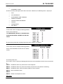
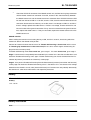
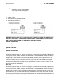
This number is composed by numbers and letters, as in the example shown below.
ZD4RA0000YSXXXXXX
KEY:
ZD4: WMI (World manufacturer identifier) code;
RA: model;
000: version variation;
0: digit free
Y year of manufacture
S: production plant (S= Scorzè);
XXXXXX: progressive number (6 digits);
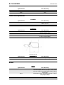
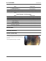
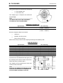
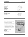
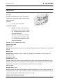
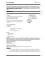
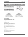
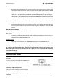
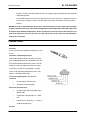
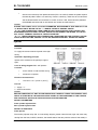
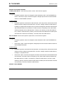
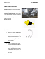
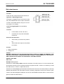
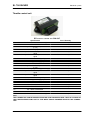
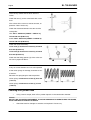
ENGINE NUMBER
The engine number is printed on the base of the
left side engine crankcase.
Engine No. ....................
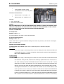
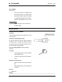
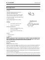
CHASSIS NUMBER
The chassis number is stamped on the right side of the headstock.
Chassis No. ....................
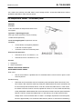
Dimensions and mass
DIMENSIONS
Specification
Max. length
Max. width
Max. height (to top fairing)
Saddle height
CHAR - 6
Desc./Quantity
2100 mm (82.68 in)
800 mm (31.50 in)
1135 mm (44.69 in)
810 mm (31.89 in)
SL 750 SHIVER
Characteristics
Specification
Wheelbase
Kerb weight (full fuel tank)
Desc./Quantity
1440 mm (56.69 in)
210 kg (463 lb)
Engine
ENGINE
Specification
Model
Type
Cylinder quantity
Overall engine capacity
Bore / stroke
Valve clearance at intake
Outlet valve clearance
Compression ratio
Start-up
Engine revs at idle speed
Clutch
Lubrication system
Air filter
Cooling
Desc./Quantity
M551M
90° longitudinal V-twin, 4-stroke, 4 valves per cylinder, 2 overhead camshafts.
2
749.9 cm³ (45.76 cu.in)
92 x 56.4 mm (3.62 x 2.22 cu.in)
0.11 - 0.18 mm (0.0043 - 0.0071 in)
0.16 - 0.23 mm (0.0063 - 0.0091 in)
11.0: 1
electric
1400 ± 100 rpm
Multiple-disk, oil-bathed clutch with control on the
left side of the handlebar
Wet crankcase. Pressure system regulated by trochoidal pump
with dry cartridge filter
Fluid
GEAR
Specification
Type
Desc./Quantity
Mechanical, 6 speeds with foot lever on the lefthand side of the engine
Transmission
GEAR RATIOS
Specification
Gear ratio
1st gear ratio
2nd gear ratio
3rd gear ratio
4th gear ratio
5th gear ratio
6th gear ratio
Final drive gear ratio
Desc./Quantity
Gear primary drive 38/71
14/36 (secondary)
17/32 (secondary)
20/30 (secondary)
22/28 (secondary)
23/26 (secondary)
24/25 (secondary)
16/44
Capacities
CAPACITY
Specification
Fuel (reserve included)
Fuel reserve
Desc./Quantity
15 l (3.30 UKgal; 3.96 USgal)
3 l (0.66 UKgal; 0.79 USgal)
CHAR - 7
SL 750 SHIVER
Characteristics
Specification
Engine oil
Fork oil quantity (for each stem):
Coolant
Seats
Vehicle max. load
Desc./Quantity
3.0 l (without oil filter change) (0.66 UKgal; 0.79
USgal)
3.2 l (without oil filter change) (0.70 UKgal; 0.85
USgal)
535 cm³ (32.65 cu.in)
1.8 l (0.40 UKgal; 0.48 USgal)
2
190 kg (418.9 lb) (Rider + passenger + luggage)
Drive chain
DRIVE CHAIN
Specification
Type
Desc./Quantity
Endless (without master link) and with sealed
links. No. of links 108
525 ZRPK
Model
Electrical system
ELECTRICAL SYSTEM
Specification
Battery
Main fuses
Auxiliary fuses
(Permanent magnet) Generator
Desc./Quantity
12V - 10 Ah
30A
3A, 10A, 15A, 20A
13.5 V - 450 W at 6000 rpm
SPARK PLUGS
Specification
Standard spark plugs
Spark plug electrode gap
Resistance
Desc./Quantity
NGK CR7EKB
0.6 ÷ 0.7 mm (0.024 ÷ 0.028 in)
5 kOhm
BULBS
Specification
Low-beam light
High-beam light
Front tail light
Turn indicator lights
License plate light
Rear tail light / stop light
Rpm indicator lighting
Multifunction display lighting
Desc./Quantity
12 V - 55 W H7
12 V - 55 W H7
12V - 5W x 2
12V - 10W
12V - 5W
12V - 5/21W x 2
LED
LED
WARNING LIGHTS
Specification
High-beam light
Right turn indicator
Left turn indicator
General warning
Gear in neutral
CHAR - 8
Desc./Quantity
LED
LED
LED
LED
LED
SL 750 SHIVER
Characteristics
Specification
Side stand down
Fuel reserve
ABS
Desc./Quantity
LED
LED
LED
Frame and suspensions
CHASSIS
Specification
Type
Steering inclination angle
Trail
Desc./Quantity
Die-cast aluminium plates and high-strength steel
tubular chassis.
24.9°
109.6°
SUSPENSIONS
Specification
Front
Travel
Rear
Wheel travel
Desc./Quantity
Upside-down hydraulic action telescopic fork, Ø
43 mm (1.69 in) stems
120 mm (4.72 in)
Oscillating swingarm and single adjustable hydraulic shock absorber
122 mm (4.80 in)
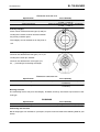
SIZES A AND B
Specification
Size A
Size B
Desc./Quantity
658.5 mm (25.93 in)
373.4 mm (14.70 in)
Brakes
BRAKES
Specification
Front
Rear
Desc./Quantity
Double floating disc, Ø 320 mm (12.60 in), radiallymounted callipers with four plungers- two of them
Ø 27 mm (1.06 in), the other two Ø 32.03 (1.26 in)
and 4 pads
Ø 240 mm (9.45 in) disc brake, Ø 35 mm (1.38 in)
twin-plunger calliper
CHAR - 9
SL 750 SHIVER
Characteristics
Wheels and tyres
WHEEL RIMS
Specification
Type
Front
Rear
Desc./Quantity
Light alloy rims with extractable bolt
3.50 x 17"
6.00 x 17"
TYRES
Specification
Tyre type (standard)
Desc./Quantity
DUNLOP SPORTMAX QUALIFIER - METZELER
M3
120/70 ZR17" (58W)
1 passenger: 2.3 bar (230 kPa) (33.36 PSI)
2 passengers: 2.5 bar (250 kPa) (36.26 PSI)
180/55 ZR17" (73W) or 190/50 ZR17" (73W)
1 passenger: 2.5 bar (250 kPa) (36.26 PSI)
2 passengers: 2.8 bar (280 kPa) (40.61 PSI)
Front
Inflation pressure
Rear
Inflation pressure
Supply
FUEL SUPPLY SYSTEM
Specification
Type
Throttle valves diameter
Fuel
Desc./Quantity
Electronic injection (Multipoint)
Ø 52 mm (2.05 in)
Premium unleaded petrol, minimum octane rating
of 95 (NORM) and 85 (NOMM)
Tightening Torques
FRAME ASSEMBLY
Name
TCEI screw fixing Shock Absorber Counterplate to
right chassis bracket - M10x30 (1)
TCEI screw fixing Fairings to engine - M12x282 (3)
Self-tapping nut fixing left Fairing to engine and
Framework to chassis fairings - M12 (7)
TC TORX screw fixing Perimeter frame to the
chassis fairings - M12x53 (4)
TCEI upper screw fixing Saddle pillar to chassis M8x30 (2)
TCEI lower screw fixing Saddle pillar to chassis M8x40 (2)
Lower self-tapping nut fixing Saddle pillar to chassis - M8 (2)
TCEI screw fixing lambda probe plate to right-side
chassis (pre-fit on right fairing - M4x10 (2)
CHAR - 10
Torque in Nm
50 Nm (36.88 lbf ft)
80 Nm (59 lbf ft)
80 Nm (59 lbf ft)
80 Nm (59 lbf ft)
25 Nm (18.44 lbf ft)
25 Nm (18.44 lbf ft)
25 Nm (18.44 lbf ft)
3 Nm (2.3 lbf ft)
SL 750 SHIVER
Characteristics
FOOTREST UNIT
Name
TCEI sunken screw fixing Footrest Support to
chassis - M8x30 (6)
Non-slip bolt (fit on driver footrest) - M8 (2)
Self-tapping TE screw for Footrest finish - M6x12
(8)
Torque in Nm
18 Nm (13.27 lbf ft)
25 Nm (18.44 lbf ft)
10 Nm (7.37 lbf ft)
STAND UNIT
Name
Screw for Stand - M10x1.25 (1)
Lower nut - M10x1.25 (1)
Self-tapping TE screw fixing Stand Plate on engine
- M8x30 (3)
Torque in Nm
10 Nm (10.34 lbf ft)
30 Nm (22.13 lbf ft)
25 Nm (18.44 lbf ft)
SWINGARM UNIT
Name
TCEI screw Swing Arms coupling - M8x70 (7)
Swingarm Pin adjustment Bushing (1)
Swingarm Pin Ring Nut (1)
Chain tensioner set screw (2)
SERPRESS nut (on chain tensioner pad set
screw) - M8 (2)
TPSI screw fixing rear stand bushing - M6x40 (2)
TBEI screw fixing chain tensioner pad - M5x12 (3)
Self-tapping TBEI screw fixing chain guard, brake
pipe protection and counterslider - M5x9 (5)
Calliper support lock pin - M12 (1)
Torque in Nm
25 Nm (18.44 lbf ft)
12 Nm (8.85 lbf ft)
60 Nm (44.25 lbf ft)
10 Nm (7.37 lbf ft)
3 Nm (2.21 lbf ft)
4 Nm (2.95 lbf ft)
50 Nm (36.88 lbf ft) - Loctite 243
FRONT SUSPENSION UNIT
Name
Stainless steel TCC screw fixing fork stems on upper and lower plates - M8x30 (6)
Headstock Ring nut - M25x1 (1)
Headstock Cap - M22x1 (1)
Screw (fasten on Fork Hub caps) - M8x40 (4)
Screw fixing the stem in wheel carrier - M10x1.5
(2)
Torque in Nm
25 Nm (18.44 lbf ft)
7 Nm (5.16 lbf ft)
100 Nm (73.75 lbf ft)
25 Nm (18.44 lbf ft)
20 Nm (14.75 lbf ft)
REAR SUSPENSION UNIT
Name
TCEI screw - M10x50 (1)
TCEI screw - M10x59 (1)
Nut - M10 (1)
Torque in Nm
50 Nm (36.88 lbf ft)
50 Nm (36.88 lbf ft)
50 Nm (36.88 lbf ft)
ENGINE SMALL PARTS UNIT
Name
Self-tapping TE screw fixing negative on engine M6x12 (3)
Torque in Nm
10 Nm (7.37 lbf ft)
CHAR - 11
SL 750 SHIVER
Characteristics
FILTER CASE UNIT
Name
SWP Self-tapping screw - M2.9x12 TCCR (2)
TCEI screw fixing negative on engine - M6x12 (1)
Torque in Nm
3 Nm (2.21 lbf ft)
10 Nm (7.37 lbf ft)
FILTER CASING SMALL PARTS UNIT
Name
SWP Self-tapping Crosshead screw - M5x20 (21)
Torque in Nm
3 Nm (2.21 lbf ft)
EXHAUST SYSTEM UNIT
Name
SERPRESS self-locking nut fixing Plate on head M8 (4)
Primary Clamp (between front/rear manifolds and
central manifold) - M6 (2)
Silencer Clamp (between central manifold and silencer) - M6 (1)
Self-tapping TE screw fixing Muffler holding Bracket to saddle pillar - M8x20 (2)
Self-tapping TE screw fixing Silencer front attachment to muffler holding bracket - M8x35 (2)
TBEI screw fixing right/left cover to silencer M6x20 (4)
TBEI lower screw fixing Licence Plate Holder
curved support - M6x20 (2)
Torque in Nm
25 Nm (18.44 lbf ft)
7 Nm (5.16 lbf ft)
7 Nm (5.16 lbf ft)
25 Nm (18.44 lbf ft)
35 Nm (25.81 lbf ft)
10 Nm (7.37 lbf ft)
10 Nm (7.37 lbf ft)
COOLING SYSTEM UNIT
Name
Self-tapping TE screw fixing Radiator, left-side, to
frame and radiator bracket to engine - M6x25 (2)
Electric fan fixing screw (3)
Screw fixing air deflector to radiator, right and left
side (2)
Torque in Nm
10 Nm (7.37 lbf ft)
3 Nm (2.21 lbf ft)
10 Nm (7.37 lbf ft)
FRONT WHEEL UNIT
Name
Wheel Pin Nut (1)
Self-tapping TE screw fixing front Disc - M8x20
=S= (12)
Torque in Nm
80 Nm (59 lbf ft)
30 Nm (22.13 lbf ft) (Loctite 243)
REAR WHEEL UNIT
Name
Self-tapping TE screw fixing rear Disc - M8x20
=S= (5)
TCEI screw fixing Anti-vibration buffer on wheel M10x30 (5)
Lower Self-locking nut fixing Crown to sprocket
carrier - M10 (5)
Wheel Pin Nut - M25x1.5 (1)
CHAR - 12
Torque in Nm
30 Nm (22.13 lbf ft) (Loctite 243)
50 Nm (36.88 lbf ft) (Loctite 2701)
50 Nm (36.88 lbf ft)
120 Nm (88.5 lbf ft)
SL 750 SHIVER
Characteristics
FRONT BRAKE UNIT
Name
Brake pipe union fixing pipe to pump - M10x1 (1)
Filler with bleed (Heng Tong) - M10x1 (2)
Self-tapping TE screw fixing Calliper M10x1.25x55 (4)
Torque in Nm
25 Nm (18.44 lbf ft)
25 Nm (18.44 lbf ft)
50 Nm (36.88 lbf ft)
REAR BRAKE UNIT
Name
TCEI screw fixing Pin to brake lever - M6x16 (1)
Rear brake Lever pin - M6 (1)
Brake pipe union - M10x1 (2)
Lock nut for fork - M6 (1)
Self-tapping TE screw fixing Pump to footrest support - M6x20 (2)
TBEI screw fixing oil pipe to swingarm and rubber
pipe to footrest support - M5x12 (4)
Self-locking nut - M6 (1)
Self-tapping TE screw - M6x16 (1)
Torque in Nm
10 Nm (7.37 lbf ft)
25 Nm (18.44 lbf ft)
25 Nm (18.44 lbf ft)
10 Nm (7.37 lbf ft)
10 Nm (7.37 lbf ft)
6 Nm (4.42 lbf ft)
10 Nm (7.37 lbf ft)
10 Nm (7.37 lbf ft)
HANDLEBAR / CONTROLS / TRASM. UNIT
Name
Anti-vibration weight terminal - M8x1 (2)
TCEI screw - M6x40 (2)
RH light switch (1)
LH light switch (1)
TCEI screw fixing lower U-bolt on fork plate M10x60 (2)
Stainless steel TCC screw fixing upper to lower Ubolt - M8x25 (4)
Torque in Nm
35 Nm (25.81 lbf ft)
10 Nm (7.37 lbf ft)
2.5 Nm (1.47 lbf ft)
2.5 Nm (1.47 lbf ft)
50 Nm (36.88 lbf ft)
25 Nm (18.44 lbf ft)
ELECTRICAL COMPONENTS UNIT
Name
SWP Self-tapping screw fixing Demand Support to
Demand - M5x14 (4)
Self-tapping TE screw fixing Demand sensor to
chassis - M6x20 (3)
Torque in Nm
3 Nm (2.21 lbf ft)
10 Nm (7.37 lbf ft)
LIGHTS UNIT / INSTRUMENT PANEL
Name
SWP Self-tapping screw fixing Instrument Panel M5x14 (6)
Special screw fixing steering head with Instrument
panel supporting plate - M6 (2)
TCEI screw fixing steering head with Instrument
panel supporting plate - M6x16 (4)
Self-locking nut - M6 (3)
TBEI screw fixing Headlight bracket to steering
base - M6x15 (2)
Lower TBEI screw fixing Rear Light - M5 (1)
Lower TCB screw fixing Rear Light - M4.2x20 (2)
Self-locking nut - M6 (4)
Torque in Nm
3 Nm (2.21 lbf ft)
10 Nm (7.37 lbf ft)
10 Nm (7.37 lbf ft)
10 Nm (7.37 lbf ft)
10 Nm (7.37 lbf ft)
4 Nm (2.95 lbf ft)
4 Nm (2.95 lbf ft)
3 Nm (2.21 lbf ft)
CHAR - 13
SL 750 SHIVER
Characteristics
TANK UNIT
Name
Self-locking nut - M5 (6)
Self-tapping TE screw - M6x30 (2)
Torque in Nm
6 Nm (4.42 lbf ft)
6 Nm (4.42 lbf ft)
FRONT BODYWORK UNIT
Name
TBEI screw fixing Under grab handles/ Tail sections / Saddle Pillar - M5x16 (2)
Self-tapping TBEI screw - M5 (7)
SWP Self-tapping Crosshead screw fixing Tail
sections to battery compartment and to fairings M5x20 (6)
Self-tapping TE screw fixing Grab handle - M8x20
(4)
TCB screw fixing battery Cover - M4x16 (2)
TBEI screw fixing Mudguard to appendix - M5x9
(2)
TBEI screw fixing Mudguard to stems - M5x9 (4)
TBEI screw fixing battery compartment to saddle
pillar - M6 (2)
TBEI screw - M5x9 (14)
TBEI screw fixing air deflectors to radiator - M6x16
(2)
Torque in Nm
4 Nm (2.95 lbf ft)
3 Nm (2.21 lbf ft)
4 Nm (2.95 lbf ft)
25 Nm (18.44 lbf ft)
3 Nm (2.21 lbf ft)
3 Nm (2.21 lbf ft)
4 Nm (2.95 lbf ft)
5 Nm (3.69 lbf ft)
3 Nm (2.21 lbf ft)
7 Nm (5.16 lbf ft)
FINISHING SMALL PARTS UNIT
Name
TCEI screw - M8x40 (1)
Self-tapping TE screw - M6x25 (2)
TCE screw fixing fuel cap - M5x16 (4)
TCEI screw fixing fuel cap - M5x30 (3)
TCEI screw fixing saddle lock to tail section M5x16 (2)
Torque in Nm
25 Nm (18.44 lbf ft)
10 Nm (7.37 lbf ft)
5 Nm (3.69 lbf ft)
5 Nm (3.69 lbf ft)
4 Nm (2.95 lbf ft)
ENGINE UNIT
Name
TCEI screw fixing Pin to gearbox lever and Gearbox Lever to knurled shaft- M6x16 (2)
Left lock nut for ball joint - M6 (1)
Lock nut for ball joint - M6 (1)
Pin fixing screw (2)
Countersunk screw fixing pin (1)
Brake pipe union fixing pipe to pump - M10x1 (1)
Filler with bleed (Heng Tong) fixing pipe to pin M10x1 (1)
Self-tapping TE screw fixing Pinion - M10x1.25x55
(1)
Torque in Nm
10 Nm (7.37 lbf ft)
10 Nm (7.37 lbf ft)
10 Nm (7.37 lbf ft)
25 Nm (18.44 lbf ft)
25 Nm (18.44 lbf ft)
50 Nm (36.88 lbf ft) - Loctite 243
COMPLETE HEAD
Name
Cam cap/head fixing screws - M6 (16)
CHAR - 14
Torque in Nm
Pre-tightening: (4.90 - 6.86) Nm ((3.61 - 5.06) lbf
ft) Tightening: (9.81 - 12.75) Nm ((7.24 - 9.40) lbf
ft)
SL 750 SHIVER
Characteristics
Name
Map sensor fitting (brass) (2)
Map sensor fitting (steel) (2)
H20 Bleed fitting (brass) (1)
H20 Bleed fitting (steel) (1)
Cap - M6 (1)
Oil cap - M10x1.25 (2)
Screw fixing fitting to bleed - M5 (4)
Special screw fixing Head Cover - M6 (8)
H20 Temperature sensor - M12x1.5 (1)
Water sensor housing threaded cap - M12x1.5 (1)
Nut fixing Stud Bolts to Head - M10x1.25 (8)
Torque in Nm
2 Nm (1.48 lbf ft) (Loctite 243)
3.50 Nm (2.58 lbf ft) (Loctite 243)
2 Nm (1.48 lbf ft) (Loctite 243)
3.50 Nm (2.58 lbf ft) (Loctite 243)
To fit flush
7 Nm (5.16 lbf ft) (3M SCOTCH GRIP 2353)
5.50 Nm (4.06 lbf ft)
8 Nm (5.90 lbf ft)
23 Nm (16.96 lbf ft)
10 Nm (7.38 lbf ft) (Loctite Drise AL 506)
Pre-torque 10 Nm (7.38 lbf ft) - Torque 13 Nm
(9.59 lbf ft) + 90° + 90° (Lubricate threads before
tightening)
Head / Cylinder / Crankcase internal side retainer
12 Nm (8.85 lbf ft)
- M6 (4)
Head / Cylinder / crankcase external side retainer
12 Nm (8.85 lbf ft)
- M6 (2)
Nut fixing Stud Bolts to Head - M6 (4)
12 Nm (8.85 lbf ft)
Nut fixing Stud Bolts to Head - M8 (2)
26 Nm (19.18 lbf ft)
Spark plug (2)
13 Nm (9.59 lbf ft)
Screw fixing Pencil to Eldor coil - M6 (2)
5.50 Nm (4.06 lbf ft)
Screw fixing camshaft retaining plate - torx M3 (8)
3 Nm (2.21 lbf ft) (Loctite 270)
Camshaft locking threaded cap
11 Nm (8.11 lbf ft)
TIMING SYSTEM
Name
Nut fixing camshaft gears (pre-tightening) - M15x1
(4)
Nut fixing camshaft gears - M15x1 (4)
Screw fixing Timing system Gear - M24x1.5 (2)
Special screw fixing Mobile / Fixed Pads - M8 (4)
Chain tensioner fixing screw - M6 (4)
Cylinder Plate fixing screw - M6 (4)
Screw for Chain tensioner adjustment - M6 (2)
Torque in Nm
30 Nm (22.13 lbf ft)
90 Nm (66.38 lbf ft)
40 Nm (29.50 lbf ft) (3M SCOTCH GRIP 2353)
19 Nm (14.01 lbf ft) (Loctite 242)
12 Nm (8.85 lbf ft)
12 Nm (8.85 lbf ft)
5.50 Nm (4.06 lbf ft)
COMPLETE CRANKCASE AND OTHER ELEMENTS
Name
Oil drainage plug - M16x1.5
Special screw for oil calibration on flywheel side
crankcase half - M10x1 (1)
Conical cap for crankshaft support lubrication M8x1 (4)
Brass Calibrated dowel fixed on crankcase unit M8 (2)
Screw fixing piston oil Jet - M5 (2)
Screw fixing Gear sensor - M5 (2)
Screw fixing Revolution sensor - M6 (1)
Tone Wheel tightening on Secondary Transmission Shaft - M16x1 (1)
Oil pressure adjustment valve, 3/4" Unf 16 (1)
Oil Pump fixing screw - M6 (2)
Screw fixing Oil Pump Cover - M3 (2)
Screw fixing oil Pump with Gear - M5 (1)
Torque in Nm
19 Nm (14.01 lbf ft)
16 Nm (11.80 lbf ft)
15 Nm (11.06 lbf ft)
5.50 Nm (4.06 lbf ft)
5.50 Nm (4.06 lbf ft) (Loctite 242)
5.50 Nm (4.06 lbf ft) (Loctite 243)
5.50 Nm (4.06 lbf ft) (Loctite 243)
43 Nm (31.72 lbf ft) (Loctite 270)
43 Nm (31.72 lbf ft)
5.50 Nm (4.06 lbf ft) (Loctite 242)
0.80 Nm (0.59 lbf ft)
8 Nm (5.90 lbf ft) (Loctite 270)
CHAR - 15
SL 750 SHIVER
Characteristics
Name
Screw fixing Gear locking pawl - M6 (1)
Screw fixing Desmodromic / Sprocket Selector M8 (1)
Selector Plate fixing screw - M5 (3)
Selector pin retainer on clutch side crankcase half
- M10x1.5 (1)
Screw fixing clutch / flywheel side crankcase half
- M6 (8)
Screw fixing clutch / flywheel side crankcase half
- M8 (9)
Oil sensor retainer on clutch side crankcase half
(1)
Suction rose fixing screw (2)
Oil Filter fitting retainer on clutch side crankcase
half (1)
Oil filter (1)
Screw fixing bearing retainer - M6 (3)
Torque in Nm
12 Nm (8.85 lbf ft)
23 Nm (16.96 lbf ft)
5.50 Nm (4.06 lbf ft)
16 Nm (11.80 lbf ft)
12 Nm (8.85 lbf ft)
26 Nm (19.18 lbf ft)
13 Nm (9.59 lbf ft)
12 Nm (8.85 lbf ft)
20 Nm (14.75 lbf ft)
14 Nm (10.33 lbf ft)
10 Nm (7.38 lbf ft) (Loctite 270)
SHAFT / FLYWHEEL / CLUTCH
Name
Nut fixing Crankshaft primaries - M24x1.5 (1)
Freewheel ring fixing screw - M6 (6)
Screw fixing Rotor - Crankshaft - M12x1.25 (1)
Screw fixing Retaining Plate - M5 (1)
Clutch fixing nut - M24x1.5 (1)
Clutch spring fixing screw - M6 (6)
Self-tapping TE screw fixing Pinion - M10x1.25x55
(1)
Connecting rod screw - M10 (4)
Torque in Nm
270 Nm (199.14 lbf ft)
14 Nm (10.33 lbf ft) (Loctite 242)
120 Nm (88.51 lbf ft)
8 Nm (5.90 lbf ft)
180 Nm (132.76 lbf ft) (Caulking)
12 Nm (8.85 lbf ft)
50 Nm (36.88 lbf ft)
20 + 50 + 70 Nm (14.75 + 36.89 + 51.63 lbf ft)
(Lubricate threads before tightening)
FLYWHEEL COVERS / CLUTCH
Name
Screw fixing Stator / Flywheel Cover - M6 (3)
Screw fixing Pick-up / Flywheel Cover - M5 (2)
Screw fixing Flywheel Cover - M6 (11)
Nut fixing Shaft pump Control inlet - M6 (1)
Oil drainage cap retainer on Clutch Cover (1)
Screw fixing Clutch side Cover - M6 (13)
Screw fixing Pump Cover / Clutch side Cover - M6
(3)
Screw fixing Pump Cover / Clutch Cover / clutch
side crankcase half - M6 (2)
Screw fixing Clutch Cover / Clutch side Cover - M6
(6)
Screw fixing "split" clutch cover gasket retainer M4 steel A2 (6)
Screw fixing Plate / Clutch Control Support - M5
(3)
Screw fixing Clutch Control Support / flywheel side
crankcase half - M6 (1)
Screw fixing Clutch Control Support / flywheel side
crankcase half - M6 (2)
Screw fixing Bracket / Starter motor - M6 (2)
CHAR - 16
Torque in Nm
9 Nm (6.64 lbf ft)
3.50 Nm (2.58 lbf ft)
12 Nm (8.85 lbf ft)
12 Nm (8.85 lbf ft) (Loctite 244)
2 Nm (1.48 lbf ft)
12 Nm (8.85 lbf ft)
12 Nm (8.85 lbf ft)
12 Nm (8.85 lbf ft)
12 Nm (8.85 lbf ft)
3 Nm (2.21 lbf ft)
5.50 Nm (4.06 lbf ft)
12 Nm (8.85 lbf ft)
12 Nm (8.85 lbf ft)
12 Nm (8.85 lbf ft)
SL 750 SHIVER
Characteristics
Name
Screw fixing engine Bracket / clutch side crankcase half - M6 (2)
Crankshaft access cover (1)
H20 Pump Rotor (1)
Screw fixing Stick-coil / Head cover - M6 (2)
Screw fixing plate / "split" clutch cover - M4 steel
A2 (6)
Torque in Nm
12 Nm (8.85 lbf ft)
4 Nm (2.95 lbf ft)
4.50 Nm (3.32 lbf ft)
5.50 Nm (4.06 lbf ft)
3 Nm (2.21 lbf ft) (Loctite 243)
THROTTLE BODY / FILTER HOUSING
Name
Intake Fitting fixing screw - M6 (8)
Screw fixing Injection Throttle Body - M6 (8)
rbw control unit fixing screw - M5 (2)
Injectors fixing screw - M6 (2)
Crosshead self-tapping screw fixing cover/ filter
casing - M5x20 (8)
Crosshead self-tapping screw fixing partition / filter
casing - M5x20 (10)
Crosshead self-tapping screw fixing side cover /
filter casing - M5x20 (3)
Crosshead self-tapping screw 5x10 (2)
Torque in Nm
12 Nm (8.85 lbf ft) (Loctite 242)
12 Nm (8.85 lbf ft) (Loctite 242)
3.50 Nm (2.58 lbf ft) (Loctite 242)
12 Nm (8.85 lbf ft) (Loctite 242)
3 Nm (2.21 lbf ft)
3 Nm (2.21 lbf ft)
3 Nm (2.21 lbf ft)
3 Nm (2.21 lbf ft)
Overhaul data
Assembly clearances
Cylinder - piston assy.
The pistons are available in four size types (A, B,
C, D) to be coupled to the four cylinder types (A,
B, C, D).
Only one type of piston ring is available.
CHAR - 17
SL 750 SHIVER
Characteristics
CYLINDER - PISTON COUPLING
Specification
Piston - cylinder coupling Type A
Piston - cylinder coupling Type B
Piston - cylinder coupling Type C
Piston - cylinder coupling Type D
Fitting clearance
Desc./Quantity
Cylinder: 91.990 - 91.977 mm (3.6216 - 3.6219 in)
Piston: 91.933 - 91.940 mm (3.6217 - 3.6197 in)
Cylinder: 91.997 - 92.004 mm (3.6219 - 3.6222 in)
Piston: 91.940 - 91.947 mm (3.6197 - 3.6199 in)
Cylinder: 92.004 - 92.011 mm (3.6222 - 3.6225 in)
Piston: 91.947 - 91.954 mm (3.6199 - 3.6202 in)
Cylinder: 92.011 - 92.018 mm (3.6225 - 3.6227 in)
Piston: 91.954 - 91.961 mm (3.6202 - 3.6205 in)
0.050 - 0.064 mm (0.00197 - 0.00252 in)
Crankcase - crankshaft - connecting rod
Two types of crankcase (1 or 2) are determined according to the diameter of the bearing hole.
The types are written on the engine crankshaft with a felt-tip pen and can be seen by removing the
clutch cover and the flywheel cover.
•
Two letters representing the main bushings and the primary wheelbase are written on the
clutch side.
•
A letter indicating the main bushing type is written on the flywheel side.
CRANKCASE SELECTION TYPE
Specification
Crankcase type 1
Crankcase type 2
CHAR - 18
Desc./Quantity
Bushing seat diameter: 53.954 - 53.960 mm
(2.1241 - 2.1244 in)
Bushing seat diameter: 53.960 - 53.966 mm
(2.1244 - 2.1246 in)
SL 750 SHIVER
Characteristics
There are two types of crankshaft for each bearing:
•
4 - 5 for flywheel side;
•
7 - 8 for clutch side.
The category type is stamped on one crankshaft
counterweight.
NOTE
THE SHAFT MAY HAVE TWO DIFFERENT
CLASSES ON THE TWO BEARINGS.
CRANKSHAFT SELECTION TYPE
Specification
Crankshaft type 4 - 7
Desc./Quantity
Main journals - diameter: 49.978 - 49.984 mm
(1.9676 - 1.9679 in)
Main journals - diameter: 49.972 - 49.978 mm
(1.9674 - 1.9676 in)
Crankshaft type 5 - 8
Once the categories below are checked:
•
crankcase
•
flywheel side main journal
•
clutch side main journal
choose the bushings to be used for coupling according to the following table.
MAIN BUSHINGS
Specification
Main journal type 4 (flywheel side)
Main journal type 4 (flywheel side)
Main journal type 5 (flywheel side)
Main journal type 5 (flywheel side)
Main journal type 7 (clutch side)
Main journal type 7 (clutch side)
Main journal type 8 (clutch side)
Main journal type 8 (clutch side)
Desc./Quantity
crankcase type 1 - half-bushings A (red)
crankcase type 2 - half-bushings B (blue)
crankcase type 1 - half-bushings B (blue)
crankcase type 2 - half-bushings C (yellow)
crankcase type 1 - half-bushings A (red)
crankcase type 2 - half-bushings B (blue)
crankcase type 1 - half-bushings B (blue)
crankcase type 2 - half-bushings C (yellow)
Crankcase category
Crankcase can be selected from two types (A or
B) according to the centre to centre distance between the primary reduction gears.
The category can be checked out on clutch-side
crankcase half, at the back.
NOTE
SHOULD THE CRANKCASE BE REPLACED,
THIS IS SUPPLIED WITH THE PRIMARY REDUCTION GEAR ALREADY COUPLED.
CHAR - 19
SL 750 SHIVER
Characteristics
CRANKCASE SELECTION TYPE
Specification
Type A crankcase
Desc./Quantity
Centre to centre distance: 110.50 - 110.54 mm
(4.3504 - 4.3519 in)
Centre to centre distance: 110.46 - 110.50 mm
(4.3488 - 4.3504 in)
Type B crankcase
Primary category
Pinion can be selected from two types (A or B) according to the centre to centre distance between
the primary reduction gears.
The category can be checked out on the pinion itself.
Crankshaft category
Shaft can be selected from two types (1 or 2) according to the crank pin diameter.
Shaft can be selected from seven types (E1,
E2, ...) according to connecting rod weight.
CRANKSHAFT SELECTION TYPE
Specification
Crankshaft type 1
Crankshaft type 2
Desc./Quantity
Crank pin diameter: 41.994 - 42.000 mm (1.65330
- 1.65354 in)
Crank pin diameter: 41.988 - 41.994 mm (1.65307
- 1.65330 in)
Bushing selection
The connecting rod has only one size category. Therefore, bushings are chosen only based on crankshaft type.
BUSHINGS
Specification
Crankshaft type 1
Crankshaft type 2
Desc./Quantity
Connecting rod type 1: half-bushings A (red)
Connecting rod type 1: half-bushings B (blue)
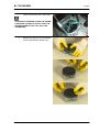
Connecting rod selection
Not all weight types are available as spare parts; only the main two. Refer to the following table for your
choice:
CHAR - 20
SL 750 SHIVER
Characteristics
CONNECTING RODS
Specification
Type E1 crankshaft
Desc./Quantity
Original connecting rod type: brown
Spare connecting rod type: brown
Original connecting rod type: blue
Spare connecting rod type: blue
Original connecting rod type: yellow
Spare connecting rod type: yellow
Original connecting rod type: green
Spare connecting rod type: green
Original connecting rod type: pink
Spare connecting rod type: pink
Original connecting rod type: black
Spare connecting rod type: black
Original connecting rod type: white
Spare connecting rod type: white
Type E2 crankshaft
Type E3 crankshaft
Type E4 crankshaft
Type E5 crankshaft
Type E6 crankshaft
Type E7 crankshaft
CAUTION
THE CONNECTING RODS OF THE SAME CRANKSHAFT MUST BE THE SAME COLOUR AND
HAVE THE SAME TYPE OF COUPLING AS THE CRANKSHAFT.
UPON REFITTING, MAKE SURE THAT THE HALF-BUSHINGS ARE OF THE SAME TYPE.
See also
Removing the clutch cover
Removing the flywheel cover
Recommended products chart
RECOMMENDED PRODUCTS
Product
AGIP RACING 4T, SAE 15W-50
Description
Engine oil
AGIP FORK 5W
AGIP MP GREASE
Fork oil
Grease for bearings, joints, couplings and levers
AGIP CHAIN GREASE SPRAY
Recommended CHAIN oil
AGIP BRAKE 4 / BRAKE 5.1
Recommended BRAKE FLUID
AGIP BRAKE 4 / BRAKE 5.1 Recommended CLUTCH FLUID
SPECIAL AGIP PERMANENT Recommended ENGINE COOLfluid
ANT
Specifications
Use top-branded oils that meet or
exceed the requirements of API
SJ/CCMC G4/ACEA A3-04/ JASO MA specifications.
SAE 5W
Alternatively to the recommended product, use top-branded
grease for roller bearings, useful
temperature range: -30°C...
+140°C (-22°F...+284°F), drop
point: 150°C...230°C (302°F...
446°F), high anticorrosive protection, good water and rust resistance.
Grease
Biodegradable coolant, ready for
use, with "long life" technology
and characteristics (pink). Freezing protection up to -40°C (-104°
F). According to CUNA 956-16
standard.
CHAR - 21
Characteristics
CHAR - 22
SL 750 SHIVER
INDEX OF TOPICS
SPECIAL TOOLS
S-TOOLS
SL 750 SHIVER
Special tools
SPECIAL TOOLS
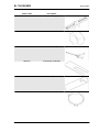
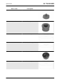
Stores code
020709Y
Description
Engine support
020710Y
Engine plate
AP8140187
Engine support stand
020711Y
Engine pinion locking
020712Y
Handle for Flywheel cover removal
020713Y
Flywheel extractor
S-TOOLS - 2
SL 750 SHIVER
Special tools
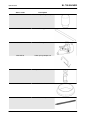
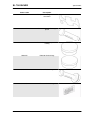
Stores code
020714Y
Description
Comparator support
020715Y
Tone wheel removal
9100896
Clutch bell locking tool
020716Y
Connecting rod locking
020717Y
Piston ring driver
AP8140302
tool for sealing ring fitting
S-TOOLS - 3
SL 750 SHIVER
Special tools
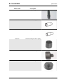
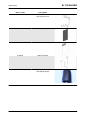
Stores code
020718Y
Description
Camshaft gear alignment pin
020719Y
Timing pin
020720Y
Timing tool
AP8140179
Valve spring compressor
020721Y
Adaptor for valve removal
020722Y
Guide for oil seal
020376Y
Punch adaptor
S-TOOLS - 4
SL 750 SHIVER
Special tools
Stores code
020629Y
Description
8 mm (0.31 in) guide
020412Y
15-mm Oil seal guide
020439Y
17-mm guide for oil seal
020263Y
Sheath for fitting the driven pulley
020365Y
22 mm (0.87 in) guide
020364Y
25 mm oil seal guide
S-TOOLS - 5
SL 750 SHIVER
Special tools
Stores code
020483Y
Description
30 mm punch
020441Y
Oil seal punch
020358Y
37 x 40 mm punch
020357Y
32 x 35 mm adaptor
020359Y
42 x 47 mm punch
020360Y
52 x 55 mm punch
S-TOOLS - 6
SL 750 SHIVER
Special tools
Stores code
020723Y
Description
Template for timing overhead
camshafts
020724Y
Gear control rod roller cage
punch
020725Y
Punch for water pump overall
sealing
020726Y
Extractor for bushings
020727Y
Punch for bushings
8140180
Extractor for bushings
S-TOOLS - 7
SL 750 SHIVER
Special tools
Stores code
8140181
Description
manometer for fuel - oil - compression pressure
8140199
Tool panel
8202222
Generic adhesive film for panel
8140426
Hooks for panel
XXXXXXX
Tool for inserting the entire rotor
shaft (being coded)
S-TOOLS - 8
INDEX OF TOPICS
MAINTENANCE
MAIN
SL 750 SHIVER
Maintenance
Maintenance chart
Adequate maintenance is fundamental to ensuring long-lasting, optimum operation and performance
of your vehicle.
To this end, aprilia offers a set of checks and maintenance services (at the owner's expense) that are
summarised in the table shown on the following page. Any minor faults should be reported without delay
to an Authorised aprilia Dealer or Sub-Dealer without waiting until the next scheduled service to solve
it.
All scheduled maintenance services must be carried out at the specified times and kilometres, even if
the stated mileage has not yet been reached. Carrying out scheduled services on time is essential to
ensure your warranty remains valid. For further information regarding Warranty procedures and ''Scheduled Maintenance'', please refer to the ''Warranty Booklet''.
NOTE
CARRY OUT MAINTENANCE OPERATIONS AT HALF THE INTERVALS SHOWN IF THE VEHICLE
IS USED IN WET OR DUSTY AREAS, OFF ROAD OR FOR SPORTING APPLICATIONS.
AT EVERY START-UP
Action
Warning light indicating error on the instrument panel - check
AFTER RUN-IN (1000 KM (625 MI))
Action
Gearing chain - Check and lubricate or replace if necessary
Transmission cables and controls - Check and clean, adjust, grease or replace if necessary
Steering bearings and steering clearance - Check and clean, adjust, grease or replace if necessary.
Control unit diagnosis - Check
Disc brakes - Check and clean, adjust or replace if necessary
Engine oil filter - Replace
General vehicle operation - Check and clean, adjust, grease or replace if necessary.
Valve clearance - Check and adjustment
Braking systems - Check and clean, adjust, grease or replace if necessary
Light circuit - Check and clean, adjust or replace if necessary
Clutch lever fluid - check and top-up if necessary
Brake fluid - check
Coolant - Check and top-up
Engine oil - Change
Tyres - Check and clean, adjust, grease or replace if necessary
Tyre pressure - Adjust
Wheels - Check and clean, adjust, grease or replace if necessary
Bolts, nuts and screws tightening - Check and clean, adjust, grease or replace if necessary
Suspensions and setting - Check and clean, adjust, grease or replace if necessary
Brake pad wear - Check and clean, adjust or replace if necessary
EVERY 1000 KM (625 MI)
Action
Gearing chain tension and lubrication - check and clean, adjust, grease or replace if necessary
MAIN - 2
SL 750 SHIVER
Maintenance
EVERY 5000 KM (3100 MI) OR 1 MONTH
Action
Tyre pressure and wear - check
EVERY 5000 KM (3100 MI)
Action
Brake pad wear - Check and clean, adjust or replace if necessary
EVERY 10,000 KM (6,215 MI)
Action
Air filter - Check and clean, replace if necessary
EVERY 20,000 KM (12,500 MILES) OR 24 MONTHS
Action
Rear shock absorber - Check
Spark plug - Replace
Gearing chain - Check and lubricate or replace if necessary
Transmission cables and controls - Check and clean, adjust, grease or replace if necessary
Steering bearings and steering clearance - Check and clean, adjust, grease or replace if necessary.
Wheel bearings - Check and clean, adjust, grease or replace if necessary
Control unit diagnosis - Check
Disc brakes - Check and clean, adjust or replace if necessary
Air filter - Replace
Engine oil filter - Replace
Fork - Check and clean, adjust and lubricate
General vehicle operation - Check and clean, adjust, grease or replace if necessary.
Cooling system - check and clean, adjust, grease or replace if necessary.
Braking systems - Check and clean, adjust, grease or replace if necessary
Light circuit - Check and clean, adjust or replace if necessary
Safety switches - Check and clean, adjust, grease or replace if necessary
Clutch lever fluid - check and top-up if necessary
Brake fluid - Check
Coolant - Check and top-up
Engine oil - Change
Light aiming - Check
Fork oil seals - Check and clean, replace if necessary
Anti-vibration buffer - check and replace if necessary
Valve clearance adjustment - Adjust
Wheels - Check and clean, adjust, grease or replace if necessary
Bolts, nuts and screws tightening - Check and clean, adjust, grease or replace if necessary
Suspensions and setting - Check and clean, adjust, grease or replace if necessary
Fuel pipes - Check and clean, adjust, grease or replace if necessary
Clutch wear - Check and replace if necessary
Brake pad wear - Check and clean, adjust or replace if necessary
EVERY 24 MONTHS
Action
Clutch control fluid - Replace
Brake fluid - Change
Coolant - Change
Fork oil - Change
MAIN - 3
SL 750 SHIVER
Maintenance
EVERY 4 YEARS
Action
Fuel pipes - Replace
Spark plug
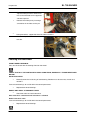
At regular intervals, remove the spark plug and clean off any carbon deposits or replace as required.
CAUTION
ALWAYS REPLACE BOTH SPARK PLUGS, EVEN IF ONLY ONE NEEDS REPLACING.
•
Remove the saddle.
•
Remove the side fairings.
In order to gain access to the spark plugs:
CAUTION
BEFORE CARRYING OUT THE FOLLOWING OPERATIONS AND IN ORDER TO AVOID BURNS,
LEAVE THE ENGINE AND MUFFLER TO COOL OFF TO AMBIENT TEMPERATURE.
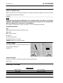
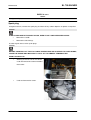
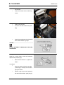
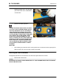
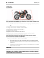
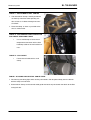
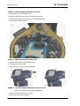
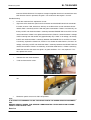
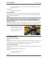
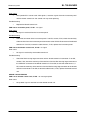
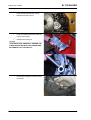
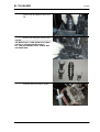
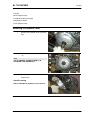
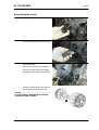
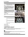
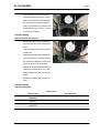
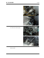
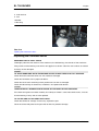
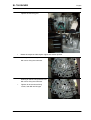
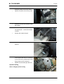
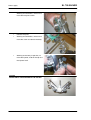
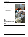
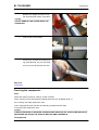
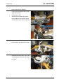
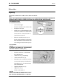
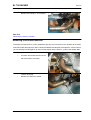
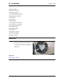
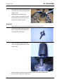
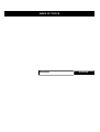
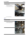
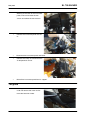
FRONT SPARK PLUG
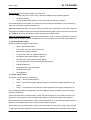
•
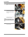
Working on the left side of the vehicle,
undo and remove the screw and collect
the washer.
•
MAIN - 4
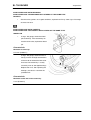
Undo and remove the screw.
SL 750 SHIVER
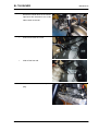
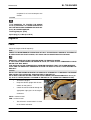
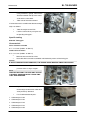
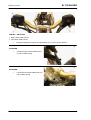
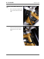
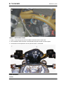
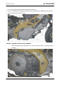
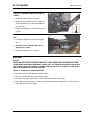
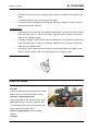
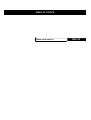
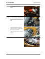
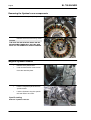
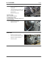
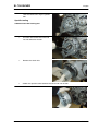
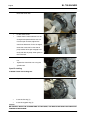
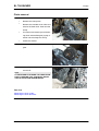
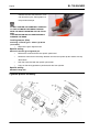
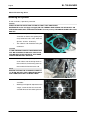
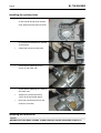
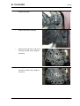
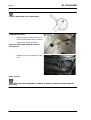
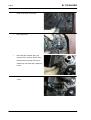
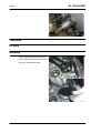
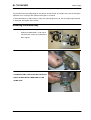
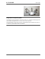
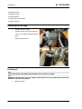
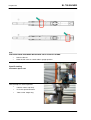
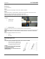
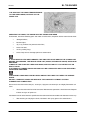
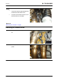
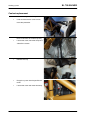
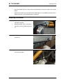
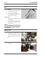
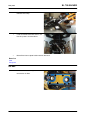
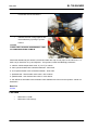
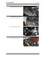
•
Maintenance
Detach the radiator towards the vehicle
right-hand side and lower it so as to be
able to work on the coil.
•
Undo and remove the screw.
•
Slide off the front coil.
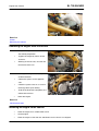
•
Unscrew and remove the front spark
plug.
MAIN - 5
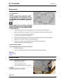
Maintenance
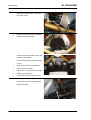
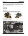
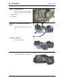
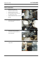
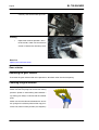
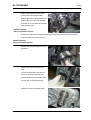
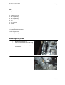
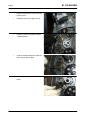
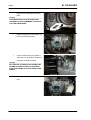
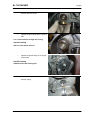
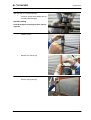
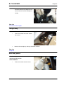
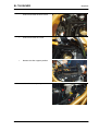
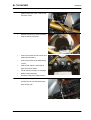
•
Working from both sides, undo and remove the screw.
•
Remove at least one side air deflector.
•
Slide off the key lock plate.
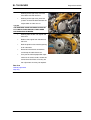
•
Undo and remove the two screws and
collect the two collars.
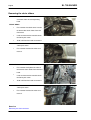
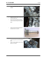
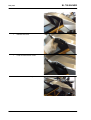
•
Undo and remove the chamber fixing
screws.
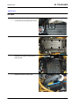
•
Slide off the "too full" and breather
pipes from the chamber.
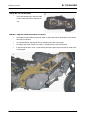
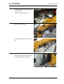
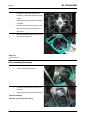
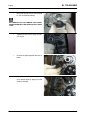
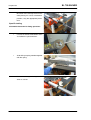
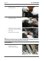
•
Lift the tank by turning it on the hinge.
•
Release the petrol pipe.
•
Disconnect the pump cable harness.
•
Working on the right side, unscrew and
remove the nut and slide off the bolt
from the left side.
MAIN - 6
SL 750 SHIVER
SL 750 SHIVER
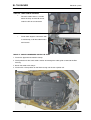
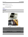
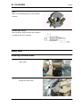
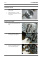
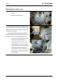
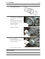
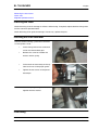
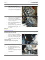
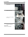
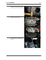
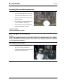
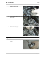
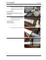
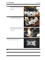
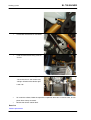
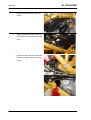
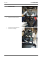
•
Lift the tank.
•
Undo and remove the rear coil fixing
Maintenance
screw.
•
Slide off the rear coil.
•
Unscrew and slide off the rear spark
plug.
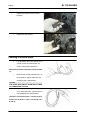
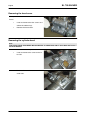
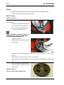
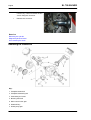
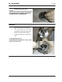
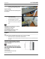
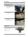
•
Check the gap between the electrodes
with a feeler thickness gauge.
CAUTION
DO NOT ATTEMPT TO READJUST THE ELECTRODE GAP.
The gap between the electrodes should be between 0.7 ÷ 0.8 mm (0.027 ÷ 0.031 in). Otherwise,
replace the spark plug (2).
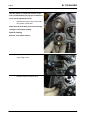
•
Make sure the washer is in good conditions.
Installation:
•
Once the washer is fitted, screw the
spark plug (2) carefully to avoid damaging the thread.
•
Tighten using the spanner supplied in
the tool kit. Make each spark plug (2)
MAIN - 7
Maintenance
SL 750 SHIVER
complete 1/2 of a turn to compress the
washer.
CAUTION
IT IS ESSENTIAL TO TIGHTEN THE SPARK
PLUG (2) PROPERLY. A LOOSE SPARK PLUG
MAY CAUSE ENGINE OVERHEATING AND RESULT IN SEVERE DAMAGE.
Locking torques (N*m)
Spark plug (2) 13 Nm (9.59 lbf ft)
Engine oil
Check
Check the engine oil level frequently.
NOTE
CARRY OUT MAINTENANCE OPERATIONS AT HALF THE INTERVALS SHOWN IF THE VEHICLE
IS USED IN WET OR DUSTY AREAS, OFF ROAD OR FOR SPORTING APPLICATIONS.
ENGINE OIL LEVEL MUST BE CHECKED WHEN THE ENGINE IS WARM.
IF YOU CHECK LEVEL WHEN THE ENGINE IS COLD, OIL LEVEL COULD TEMPORARILY DROP
BELOW THE "MIN" MARK.
THIS SHOULD NOT BE CONSIDERED A PROBLEM PROVIDED THAT THE ALARM WARNING
LIGHT AND THE ENGINE OIL PRESSURE ICON ON THE DISPLAY DO NOT TURN ON SIMULTANEOUSLY.
CAUTION
DO NOT LET THE ENGINE IDLE WITH THE VEHICLE AT STANDSTILL TO WARM UP THE ENGINE
AND OBTAIN THE OPERATING TEMPERATURE OF ENGINE OIL.
OIL IS BEST CHECKED AFTER A TRIP OR AFTER TRAVELLING APPROXIMATELY 15 km (10
mi), OUT OF TOWN (ENOUGH TO WARM UP ENGINE OIL TO OPERATING TEMPERATURE).
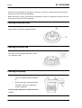
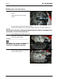
•
Shut off the engine.
•
Keep the vehicle upright with the two
wheels on the ground.
•
Check the correct oil level through the
appropriate sight glass on the engine
crankcase.
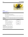
MAX = maximum level.
MIN = minimum level
•
The oil level is correct when it is close
to the "MAX" reference.
MAIN - 8
SL 750 SHIVER
Maintenance
Replacement
Check the engine oil level frequently.
To change the oil:
CAUTION
HOT OIL IS MORE FLUID AND WILL DRAIN
OUT MORE EASILY AND COMPLETELY; IDEAL TEMPERATURE IS REACHED AFTER THE
ENGINE HAS RUN FOR ABOUT TWENTY MINUTES.
OIL BECOMES VERY HOT WHEN THE ENGINE
IS HOT; BE CAREFUL NOT TO GET BURNED
WHEN CARRYING OUT THE OPERATIONS DESCRIBED BELOW.
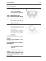
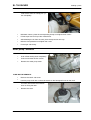
•
Use a cloth to wipe off any mud deposit on the area next to the filler plug (1).
•
Place a container with + 4000 cm³ (244 cu.in) capacity under the drainage plug (2).
•
Unscrew and remove the drainage plug (2).
•
Unscrew and remove the filler plug (1).
•
Drain the oil into the container; allow several minutes for oil to drain out completely.
•
Replace the sealing washer of the drainage plug (2).
•
Remove any metal scrap attached to the drainage plug (2) magnet.
•
Screw and tighten the drainage plug (2).
Locking torques (N*m)
Oil drainage plug - M16x1.5 19 Nm (14.01 lbf ft)
•
Replace the oil filter.
•
Fill up to the right engine oil level by adding recommended engine oil.
See also
Engine oil filter
Check
Engine oil filter
•
Drain off the engine oil.
•
Remove the oil filter.
•
Fit a new engine oil filter.
•
Add engine oil up to the correct level.
CAUTION
NEVER REUSE AN OLD FILTER.
See also
MAIN - 9
Maintenance
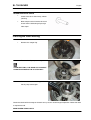
Replacement
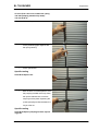
Air filter
•
Remove the fuel tank.
•
Disconnect the air temperature sensor.
•
Undo and remove the eight screws.
•
Remove the clamp and slide off the
blow-by tube.
•
MAIN - 10
Remove the filter casing cover.
SL 750 SHIVER
SL 750 SHIVER
•
Maintenance
Working on both ducts, turn the upper
part of the intake ducts anticlockwise
and remove it.
•
Remove the filtering element.
COVER THE INTAKE DUCTS WITH A CLEAN
CLOTH SO THAT FOREIGN BODIES DO NOT
GET INTO THE INLET DUCTS. UPON REFITTING AND BEFORE PLACING THE FILTER
CASING COVER, MAKE SURE NEITHER THE
CLOTH NOR ANY OTHER OBJECT HAS BEEN
LEFT INSIDE THE FILTER CASING. MAKE
SURE THE FILTERING ELEMENT IS CORRECTLY PLACED SO THAT UNFILTERED AIR
DOES NOT FLOW IN. DO NOT FORGET THAT
EARLY WEAR OF THE PISTON RINGS AND
THE CYLINDER CAN BE CAUSED BY A MALFUNCTIONING OR MISPLACED FILTERING
ELEMENT.
REFITTING
•
Upon refitting, pay attention when inserting intake ducts and check that the bayonet joint is
released once every duct has been inserted and rotated.
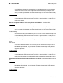
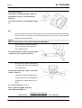
Checking the valve clearance
The following operation can be carried out also with the engine fitted on the vehicle.
•
Remove both head covers.
CAUTION
WHENEVER THE HEAD COVER IS REMOVED, ALL FOUR RUBBER RINGS AND THE GASKET
SHOULD BE REPLACED.
MAIN - 11
Maintenance
•
SL 750 SHIVER
Using a thickness gauge, measure the
distance between the tip of the crankshaft and the valve bowl.
•
Take note of the measurement.
If valve clearance is not within the tolerance range,
adjust as follows:
•
Take the engine to the TDC.
•
Lock the camshafts by using the corresponding timing pins.
Specific tooling
020719Y Timing pin
Characteristic
Valve clearance at intake
0.11 - 0.18 mm (0.0043 - 0.0071 in)
Outlet valve clearance
0.16 - 0.23 mm (0.0063 - 0.0091 in)
•
Remove one camshaft at a time
•
Leave the other camshaft assembled and blocked by means of the timing pin.
CAUTION
IF BOTH CAMSHAFTS ARE REMOVED, THE ENGINE SPINS MAKING TIMING NECESSARY.
•
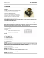
Remove the bowl tappets and the adjustment shims using a magnet.
NOTE
GREASE THE BOWL TAPPETS AND THE ADJUSTMENT SHIMS PROPERLY EACH TIME
THEY ARE REMOVED.
•
Replace calibrated pads with a pad
thick enough to correct the valve clearance previously detected.
•
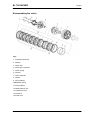
List of calibrated break pads:
1. Calibrated pad 2.60
2. Calibrated pad 2.65
3. Calibrated pad 2.70
4. Calibrated pad 2.75
5. Calibrated pad 2.80
MAIN - 12
SL 750 SHIVER
Maintenance
6. Calibrated pad 2.85
7. Calibrated pad 2.90
8. Calibrated pad 2.95
9. Calibrated pad 3.00
10.Calibrated pad 3.05
11.Calibrated pad 3.10
12.Calibrated pad 3.15
13.Calibrated pad 3.20
14.Calibrated pad 3.25
15.Calibrated pad 3.30
16.Calibrated pad 3.35
17.Calibrated pad 3.40
18.Calibrated pad 2.55
19.Calibrated pad 2.50
20.Calibrated pad 2.45
21.Calibrated pad 2.40
CAUTION
BEFORE REFITTING HEAD COVERS, CLEAN HEAD AND COVER SURFACES CAREFULLY.
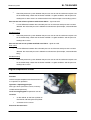
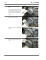
•
Apply THREEBOND on the head cover
perimeter along the gasket housing.
•
Apply THREEBOND on the head in the
areas indicated in the figure.
See also
Removing the head cover
MAIN - 13
Maintenance
MAIN - 14
SL 750 SHIVER
INDEX OF TOPICS
TROUBLESHOOTING
TROUBL
SL 750 SHIVER
Troubleshooting
TROUBLESHOOTING PROCEDURE IF THE EFI WARNING LIGHT ON THE INSTRUMENT PANEL
TURNS ON OR IF THERE IS ABNORMAL ENGINE PERFORMANCE
CAUTION
BEFORE CARRYING OUT ANY TROUBLESHOOTING, CAREFULLY READ THE GENERAL CONCEPTS OF ELECTRICAL TROUBLESHOOTING FOUND AT THE BEGINNING OF THE CHECKS
AND CONTROLS SECTION IN THE ELECTRICAL SYSTEM CHAPTER.
•
1 - THE "EFI" WARNING LIGHT IS ON AND THE WORD "SERVICE" IS SHOWN or THE
"EFI" WARNING LIGHT IS FLASHING AND THE WORDS "URGENT SERVICE" ARE
SHOWN or ONE OF THE TWO SITUATIONS TAKES PLACE AND IS SUDDENLY OUT or
THERE IS ABNORMAL ENGINE PERFORMANCE
•
2 - CONNECT TO THE CONTROL UNIT THROUGH AXONE (MINIMUM VERSION: 5.1.5)
BY SELECTING "SELF- DIAGNOSIS, APRILIA, SL 750 SHIVER"
•
3 - ARE CURRENT "ATT" or STORED "MEM" ERRORS SHOWN IN THE "ERRORS DISPLAY" SCREEN PAGE?
YES, go to 4; NO, go to 12.
•
4 - IF THE ERROR IN THE CENTRAL WINDOW IS SELECTED AND "?" IS DISPLAYED,
PRESS THE KEY "?" TO OBTAIN FURTHER INFORMATION ABOUT THE ERROR. THEN
GO TO THE "ELECTRICAL SYSTEM/CHECKS AND CONTROLS" CHAPTER AND READ
THE INFORMATION CONCERNING THE DEFECTIVE COMPONENT
•
5 - ACCORDING TO WHAT IS INDICATED ABOUT THE ERROR/S, PROCEED AS SUGGESTED AND SOLVE THE PROBLEM
•
6 - WAS THE PROBLEM SOLVED BY REPLACING THE MARELLI CONTROL UNIT?
YES, go to 7; NO, go to 8.
•
7 - READ THE ACTIVATION PROCEDURE FOR A NEW CONTROL UNIT ON THE "ELECTRICAL SYSTEM/CHECKS AND CONTROLS/ECU/MARELLI CONTROL UNIT" CHAPTER - END
•
8 - SELECT "ERROR CLEARING" FROM THE "DEVICES ACTIVATION (INJECTOR)"
SCREEN PAGE
•
9 - WAS THE PROBLEM SOLVED BY REPLACING THE THROTTLE GRIP SENSOR
(DEMAND) OR THE THROTTLE BODY?
NO, END; YES, go to 10
•
10 - READ THE RESET PROCEDURE ON THE "ELECTRICAL SYSTEM/CHECKS AND
CONTROLS/THROTTLE GRIP POSITION SENSOR OR THROTTLE BODY" CHAPTER END
•
11 - CHECK IF THERE ARE CURRENT OR STORED ERRORS DETECTED BY THE INSTRUMENT PANEL REFERRING TO THE "DIAGNOSIS" CHAPTER, "INSTRUMENT
TROUBL - 2
SL 750 SHIVER
Troubleshooting
PANEL ERRORS" SECTION. IF THERE ARE ERRORS PRESENT, SOLVE THE FAILURE
AND SELECT "CLEAR ERRORS"; IF THERE ARE NO ERRORS PRESENT, go to 12
•
12 - IN THE "ENGINE PARAMETER READING" SCREEN PAGE, DOES THE "AIR TEMPERATURE" PARAMETER INDICATE A VALUE EQUIVALENT TO ROOM TEMPERATURE?
YES, go to 13; NO, note A
•
13 - IN THE "ENGINE PARAMETER READING" SCREEN PAGE, DOES THE ENGINE
TEMPERATURE PARAMETER WITH COLD ENGINE INDICATE A VALUE SIMILAR TO
THAT OF THE AIR TEMPERATURE PARAMETER? AFTER STARTING THE ENGINE,
DOES THE PARAMETER INCREASE GRADUALLY INDICATING A CORRECT VALUE?
YES, go to 14; NO, note B
•
14 - IN THE "ENGINE PARAMETER READING" AND THE "LAMBDA SENSOR CORRECTION" SCREEN PAGES, WITH ENGINE AT IDLE AND ENGINE TEMPERATURE AT >
90°C, DOES THE VALUE VARY WITHIN THE 0.9 - 1.1 RANGE?
YES, go to 15; NO, note C
•
15 - IN THE "ENGINE PARAMETER READING" SCREEN PAGE AND WITH ENGINE AT
IDLE, ARE "FRONT THROTTLE CORRECTION PARAMETERS" OR "REAR THROTTLE
CORRECTION" WITHIN THE (-0.4° - +0.4°) RANGE? AND IN THE SAME SCREEN PAGE,
ARE THE "FRONT THROT., POT. 1 (DEGREES)" AND "REAR THROT., POT. 1 (DEGREES)" PARAMETERS > OR = TO 0.5° WITH ENGINE AT IDLE? CAUTION: THE
DIFFERENCE OF THE THROTTLE CORRECTION VALUES BETWEEN THE REAR AND
FRONT CYLINDER MUST NOT BE >0.4°
YES, go to 16; NO, note D
•
16 - CHECK: ENGINE REVOLUTION SENSOR, FUEL PRESSURE, INJECTORS (MECHANICAL OPERATION), COILS (SPARK), ENGINE MECHANICS - END
Note A: SEE THE "ELECTRICAL SYSTEM/CHECKS AND CONTROLS/AIR TEMPERATURE SENSOR" CHAPTER.
Note B: SEE THE "ELECTRICAL SYSTEM/CHECKS AND CONTROLS/ENGINE TEMPERATURE
SENSOR" CHAPTER.
Note C: SEE THE "ELECTRICAL SYSTEM/CHECKS AND CONTROLS/LAMBDA PROBE" CHAPTER.
Note D: SEE THE "ELECTRICAL SYSTEM/CHECKS AND CONTROLS/THROTTLE BODY" CHAPTER.
See also
Checks and inspections
TROUBL - 3
SL 750 SHIVER
Troubleshooting
Engine
The engine does not start
THE ENGINE DOES NOT START
CAUTION
AXONE SHOULD BE WORKING PROPERLY AND UPGRADED TO THE 5.1.5 VERSION MINIMUM.
CAUTION
BEFORE ANY TROUBLESHOOTING, MAKE SURE THAT:
1) BATTERY VOLTAGE IS ABOVE 12V;
2) THE MAIN 30A FUSE IS NOT DAMAGED AND IS ADEQUATELY FITTED;
3) AUXILIARY FUSES ARE NOT DAMAGED AND ARE ADEQUATELY FITTED.
NOTE
THE RELAY NUMBER SPECIFIED REFERS TO THE WIRING DIAGRAM. THE POSITION OF THE
RELAY ON THE VEHICLE IS INDICATED IN THE "ELECTRICAL SYSTEM/COMPONENT LAYOUT/
RELAY LAYOUT" CHAPTER.
•
1 - WITH THE KEY TURNED TO "ON", THE INSTRUMENT PANEL LIGHTS UP BUT NO
FAILURE INDICATION IS SHOWN. IS THE FUEL PUMP ACTIVATED?
YES, go to 27; NO, go to 2
•
2 - DOES AXONE COMMUNICATE WITH THE CONTROL UNIT?
YES, go to 3; NO, go to 4
•
3 - ACTIVATE ONE INJECTOR BY MEANS OF AXONE ("DEVICES ACTIVATION"
SCREEN PAGE, INJECTOR ICON): IS THE INJECTOR ACTIVATED?
YES, go to 17; NO, go to 12
•
4 -WITH THE KEY TURNED TO "OFF" CHECK IF THERE IS VOLTAGE ON THE ORANGE/
RED CABLE OF THE MAIN INJECTION RELAY (POLARISED) 41.
YES, go to 6; NO, go to 5
•
5 - INSPECT IF THERE IS AN INTERRUPTION IN THE ORANGE/RED CABLE FROM THE
MAIN INJECTOR RELAY (POLARISED) TO THE BATTERY POSITIVE.
•
6 - WITH THE KEY TURNED TO "ON" CHECK IF THERE IS VOLTAGE ON THE GREEN/
BLACK CABLE OF THE MAIN INJECTION RELAY (POLARISED) 41.
OK, go to 8; NOT OK, go to 7
•
7 - INSPECT THE GREEN/BLACK CABLE FROM THE MAIN INJECTION RELAY (POLARISED) 41 TO THE KEY SWITCH - END
•
8 - IS THE BLUE CABLE GROUNDED?
YES, go to 10; NO, go to 9
•
9 - RESTORE THE CABLE HARNESS.
•
10 - CHECK IF THERE IS VOLTAGE ON THE RED/BLACK CABLE.
NOT OK, go to 11; OK, go to 12
TROUBL - 4
SL 750 SHIVER
Troubleshooting
•
11 - REPLACE THE MAIN INJECTOR RELAY (POLARISED) 41 - END
•
12 - CHECK IF THERE IS VOLTAGE ON THE ORANGE/RED CABLE OF THE AUXILIARY
INJECTION RELAY (POLARISED) 42.
YES, go to 13; OK, go to 14
•
13 - CHECK IF THERE IS VOLTAGE ON THE YELLOW/PURPLE CABLE.
OK, go to 15; NOT OK, go to 16
•
14 - RESTORE THE CABLE HARNESS - END
•
15 - SET THE KEY TO "OFF" AND THEN "ON": DOES THE VOLTAGE ON THE YELLOW/
PURPLE CABLE REACH APPROX. 1-2V FOR 2 SECONDS?
YES, go to 17; NO, go to 18
•
16 - REPLACE THE AUXILIARY INJECTOR RELAY (POLARISED) 42 - END
•
17 - WHEN THE KEY IS TURNED TO "OFF", CHECK CONTINUITY AND GROUND INSULATION OF THE RED/BROWN CABLE FROM THE AUXILIARY INJECTION RELAY 42
TO THE FUEL PUMP CONNECTOR.
YES, go to 20; NO, go to 19
•
18 - WHEN THE KEY IS TURNED TO "OFF", CHECK CONTINUITY AND GROUND INSULATION OF THE YELLOW/PURPLE CABLE FROM THE RELAY TO PIN 62, VEHICLE
CONNECTOR.
YES, go to 22; NO, go to 21
•
19 - RESTORE THE CABLE HARNESS.
•
20 - CHECK THERE IS GROUND INSULATION FOR THE BLUE CABLE OF THE PUMP
CONNECTOR.
OK, go to 24; NOT OK, go to 23
•
21 - RESTORE THE CABLE HARNESS - END
•
22 - CHECK THE VEHICLE CONNECTOR.
OK, go to 25; NOT OK, go to 26
•
23 - RESTORE THE CABLE HARNESS - END
•
24 - CHECK IF THE PUMP RESISTANCE IS APPROX. 1 OHM. REPLACE THE PUMP IF
THE RESISTANCE VALUE IS NOT THAT SPECIFIED - END
•
25 - REPLACE THE CONTROL UNIT - END
•
26 - RESTORE THE CABLE HARNESS - END
•
27 - DOES THE MOTOR TURN WHEN THE STARTER BUTTON IS PRESSED?
YES, go to 29; NO, go to 28
•
28 - WHAT DOES THE "START-UP ENABLING SWITCH" STATUS ON AXONE (DEVICE
STATUS/ICON "0/1" SCREEN PAGE) MEAN?
YES, go to 43; NO, go to 64
TROUBL - 5
SL 750 SHIVER
Troubleshooting
•
29 - VOLTAGE TO THE YELLOW/PINK CABLE OF THE RETENTION RELAY (START-UP
LOGIC) 39
OK, go to 30; NOT OK, go to 31
•
30 - WITH THE RETENTION RELAY (START-UP LOGIC) 39 DISCONNECTED, KEEP
THE STARTER BUTTON PRESSED AND CHECK IF THERE IS APPROX. 1-2V VOLTAGE
IN THE YELLOW/RED CABLE
OK, go to 32; NOT OK, go to 33
•
31 - RESTORE THE CABLE HARNESS
•
32 - CHECK THE GROUND CONNECTION OF THE BLUE CABLE OF THE RETENTION
RELAY (START-UP LOGIC) 39
OK, go to 34; NOT OK, go to 35
•
33 - RESTORE THE CABLE HARNESS
•
34 - CHECK THAT THE RETENTION RELAY (START-UP LOGIC) 39 WORKS CORRECTLY
OK, go to 36; NOT OK, go to 37
•
35 - RESTORE THE CABLE HARNESS
•
36 - CHECK CONTINUITY OF THE PINK/BLACK CABLE OF THE RETENTION RELAY
(START-UP LOGIC) 39 TO PIN 14 VEHICLE CONNECTOR
OK, go to 38; NOT OK, go to 39
•
37 - REPLACE THE RETENTION RELAY (START-UP LOGIC) 39
•
38 - CHECK THE VEHICLE CONNECTOR (PIN 14)
OK, go to 40; NOT OK, go to 41
•
39 - RESTORE THE CABLE HARNESS
•
40 - REFER TO THE CHAPTER ON "ELECTRICAL SYSTEM/ CHECKS AND CONTROLS/
ENGINE REVOLUTION SENSOR"; FOLLOW THE TROUBLESHOOTING STEPS IN THE
SECTION REFERRING TO "AXONE: ELECTRICAL ERRORS".
CAUTION: failure NOT identified, go to 42; failure identified, END
•
41 - RESTORE THE CABLE HARNESS
•
42 - CHECK INJECTORS AND ENGINE FOR CORRECT MECHANICAL OPERATION,
CHECK FUEL CIRCUIT PRESSURE.
•
43 - WHEN THE STARTER BUTTON IS PRESSED, DOES THE VOLTAGE TO THE YELLOW/PINK CABLE OF THE CONTROL RELAY (START-UP LOGIC) 40 REACH APPROX.
ZERO?
YES, go to 44; NO, go to 45
TROUBL - 6
SL 750 SHIVER
•
Troubleshooting
44 - CHECK IF THERE IS VOLTAGE IN THE RED/BLACK CABLES ON THE CONTROL
RELAY (START-UP LOGIC) 40
YES, go to 50; NO, go to 51
•
45 - CHECK CONTINUITY AND GROUND INSULATION OF THE YELLOW/PINK CABLE
FROM THE RELAY TO THE ENGINE CONNECTOR (PIN 2)
OK, go to 47; NOT OK, go to 46
•
46- RESTORE THE CABLE HARNESS - END
•
47 - CHECK THE CONTROL UNIT CONNECTOR
OK, go to 49; NOT OK, go to 48
•
48 - RESTORE THE CABLE HARNESS - END
•
49 - REPLACE THE CONTROL UNIT - END
•
50 - PRESSING THE STARTER BUTTON, DISCONNECT THE CONNECTOR OF THE
WHITE/SKY BLUE AND WHITE/RED CABLES OF THE START-UP RELAY 36, AND
CHECK IF THERE IS VOLTAGE TO THE YELLOW/RED CABLE OF THE CONTROL RELAY- START-UP LOGIC- 40
OK, go to 52; NOT OK, go to 53
•
51 - REPLACE THE RELAY - END
•
52 - PRESSING THE STARTER BUTTON, CHECK IF THERE IS VOLTAGE TO THE YELLOW/RED CABLE OF THE START-UP RELAY
OK, go to 54; NOT OK, go to 55
•
53 - REPLACE THE RELAY - END
•
54 - CHECK IF THE BLUE CABLE OF THE START-UP RELAY 36 IS GROUNDED
OK, go to 56; NOT OK, go to 57
•
55 - RESTORE THE CABLE HARNESS -END
•
56 - WITH THE KEY TURNED TO "OFF" CHECK IF THERE IS VOLTAGE TO THE REAR
RED CABLE (WITH PROTECTION COVER) OF THE START-UP RELAY 36
OK, go to 58; NOT OK, go to 59
•
57 - RESTORE THE CABLE HARNESS -END
•
58 - PRESSING THE STARTER BUTTON, CHECK IF THERE IS VOLTAGE TO THE
FRONT RED CABLE OF THE START-UP RELAY 36
OK, go to 60; NOT OK, go to 61
•
59 - RESTORE THE CABLE HARNESS
•
60 - CHECK CONTINUITY OF THE RED CABLE BETWEEN THE START-UP RELAY 36
AND THE STARTER MOTOR
YES, go to 62; NO, go to 63
TROUBL - 7
SL 750 SHIVER
Troubleshooting
•
61 - REPLACE THE START-UP RELAY 36 - END
•
62 - REPLACE THE STARTER MOTOR - END
•
63 - RESTORE THE CABLE HARNESS - END
•
64 - WHAT DOES THE "FALL SENSOR" STATUS ON AXONE (DEVICE STATUS/ICON
"0/1" SCREEN PAGE) MEAN?
If "NORMAL" is shown, go to 65; If "TIP OVER" is shown, go to 68
•
65 - WITH THE SWITCH SET TO "RUN", WHAT DOES THE "RUN-STOP SWITCH" STATUS ON AXONE ("DEVICE STATUS/ICON "0/1" SCREEN PAGE) MEAN?
If "RUN" is shown, go to 66; If "STOP" is shown, go to 67
•
66 - USING AXONE CHECK THAT THE SIDE STAND, NEUTRAL SENSOR AND CLUTCH
SENSOR FUNCTION CORRECTLY; OPERATE ANY DEVICE AND CHECK THE SUITABLE INDICATION ON THE "DEVICE STATUS/ICON "0/1" SCREEN PAGE
If "MALFUNCTION" is shown, go to 71; If "CORRECT OPERATION" is shown, go to 72
•
67 - REFER TO THE CHAPTER ON "ELECTRICAL SYSTEM/CHECKS AND CONTROLS/
FALL SENSOR; INDICATION ON AXONE ALWAYS STOP- END
•
68 - IS THE SENSOR VERTICAL?
YES, go to 69; NO, go to 70
•
69 - REFER TO THE CHAPTER ON "ELECTRICAL SYSTEM/CHECKS AND CONTROLS/
FALL SENSOR; INDICATION ON AXONE ALWAYS TIP OVER - END
•
70 - SET THE SENSOR TO THE CORRECT POSITION - END
•
71 - ACCORDING TO THE FAILURE, REFER TO CHAPTER ON "ELECTRICAL SYSTEM/
CHECKS AND CONTROLS/GEAR IN NEUTRAL SENSOR", or "CLUTCH LEVER SENSOR" or "SIDE STAND SENSOR" - END
•
72 - REPLACE THE CONTROL UNIT - END
TROUBL - 8
INDEX OF TOPICS
ELECTRICAL SYSTEM
ELE SYS
Electrical system
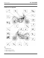
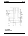
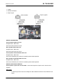
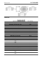
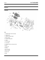
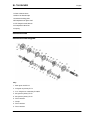
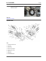
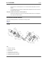
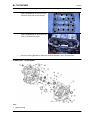
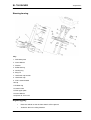
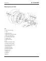
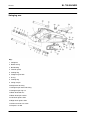
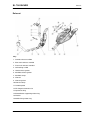
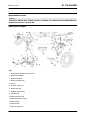
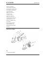
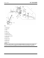
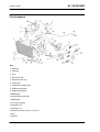
Components arrangement
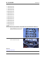
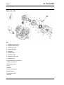
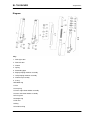
Key
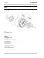
1. Revolution sensor
2. Intake air pressure sensor
3. Intake air temperature sensor
ELE SYS - 2
SL 750 SHIVER
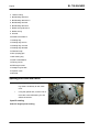
SL 750 SHIVER
Electrical system
4. Instrument panel
5. Air temperature sensor for instrument panel indication
6. Front headlamp
7. Start-up relay
8. Coils
9. Spark plugs
10.Starter motor
11.Rear light
12.Auxiliary fuses
13.Main fuses
14.Throttle grip position sensor
15.Gear in neutral sensor
16.Revolution sensor - pick up
17.Engine temperature sensor
18.Throttle control unit
19.Lambda probe
20.Fall sensor
21.Main injection relay
22.Engine control unit
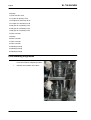
CAUTION
A RELAY CANNOT BE IDENTIFIED BASED ONLY ON THE FOLLOWING INDICATIONS: THIS
SHOULD BE DONE ALSO IDENTIFYING THE COLOUR OF THE RELAY CABLES.
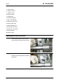
RELAY LAYOUT ON THE WIRING DIAGRAM AND ON THE VEHICLE
LIGHT LOGIC RELAY
•
Location on the wiring diagram: 9
•
Location on the vehicle: under the fuel tank, left side, second relay starting from the front.
START-UP RELAY
•
Location on the wiring diagram: 36
•
Location on the vehicle: under the fuel tank, right side, fifth relay starting from the front, below
in relation to the line of the other relays.
RETENTION RELAY
•
Location on the wiring diagram: 39
•
Location on the vehicle: under the fuel tank, right side, second relay starting from the front.
CONTROL RELAY
•
Location on the wiring diagram: 40
•
Location on the vehicle: under the fuel tank, right side, first relay starting from the front.
MAIN INJECTION RELAY
ELE SYS - 3
Electrical system
•
Location on the wiring diagram: 41
•
Location on the vehicle: under the saddle.
SL 750 SHIVER
AUXILIARY INJECTION RELAY
•
Location on the wiring diagram: 42
•
Location on the vehicle: under the fuel tank, right side, third relay starting from the front.
FAN CONTROL RELAY
•
Location on the wiring diagram: 44
•
Location on the vehicle: under the fuel tank, left side, first relay starting from the front.
HIGH-BEAM LIGHTS RELAY
•
Location on the wiring diagram: 66
•
Location on the vehicle: under the fuel tank, left side, third relay starting from the front.
RECOVERY LOGIC RELAY (URGENT SERVICE)
•
Location on the wiring diagram: 67
•
Location on the vehicle: under the fuel tank, right side, fourth relay starting from the front.
Electrical system installation
INTRODUCTION
Scope and applicability
The position of the cable harnesses, how they are fixed to the motorcycle and potential problems are
defined on the following sections in order to reach the objectives of vehicle reliability.
Materials used and corresponding quantities
The electrical system consists of the following cable harnesses and parts:
•
1 Main Cable Harness
•
1 Filter Casing Cable Harness
•
1 Rear light Cable harness
•
1 Relay-Starter Motor Cable
•
1 Battery - Engine Ground Cable
•
2 Caps for Magura Switches
•
1 Injection Main Relay
•
6 Relays 12 V / 30 A
•
1 Start-up Relay
•
Medium black clamps 178 x 4 (7.01 x 0.16 in)
•
Small black clamps 98 x 2.5 (3.86 x 0.01 in)
•
1 10-cm (3.94 in) spiral for start-up cable
•
1 Pick-Up divider cable harness (if fitted)
Vehicle sections
The wiring distribution is subdivided in three essential sections, as indicated in the figure.
ELE SYS - 4
SL 750 SHIVER
Electrical system
1. Front section
2. Central section
3. Rear section
SPECIAL CHECKS FOR THE CORRECT CONNECTION AND LAYING OF CABLES
Carry out the checks described below once the electrical system is refitted, connectors reconnected and clamps and retainers restored.
•
Check the connector block for connections and correct tightening in the following connectors.
1. Instrument panel connector: FRONT SECTION, TABLE J.
2. Handgrip sensor connectors: CENTRAL SECTION, TABLE F.
3. Pick Up Connector: CENTRAL SECTION, TABLE Q.
4. Side Stand Switch Connector.
5. Regulator Connector: CENTRAL SECTION, TABLE H.
6. Front cylinder coil and rear cylinder coil connectors: CENTRAL SECTION, TABLE F.
7. Filter Housing Connectors: CENTRAL SECTION, TABLE F.
8. ECU and Ground Lead Connectors for the filter casing: CENTRAL SECTION, TABLE A.
9. Fuel Pump Connector: CENTRAL SECTION, TABLE F.
10.Key Connector - Right Light Switch Connectors - Left Light Switch Connectors: Connectors inside
the housing behind the radiator: FRONT SECTION, TABLE I.
•
THE CONNECTORS LISTED ARE CONSIDERED CRITICAL IN COMPARISON WITH
THE OTHERS BECAUSE THE VEHICLE WILL STOP IF THEY ARE ACCIDENTALLY DISCONNECTED.
•
Undoubtedly the connection of the rest of connectors is also important and essential for the
correct operation of the vehicle.
Front side
CAUTION
ONCE THE ELECTRICAL SYSTEM IS REFITTED, THE CONNECTORS RECONNECTED AND
CLAMPS AND RETAINERS RESTORED, CARRY OUT THE CHECKS INDICATED UNDER "SPECIAL CHECKS FOR THE CORRECT CONNECTION AND LAYING OF CABLES" IN THE "ELECTRICAL SYSTEM INSTALLATION" SECTION.
ELE SYS - 5
Electrical system
SL 750 SHIVER
TABLE A - SWITCHES
1. Right switch cable harness
2. Left switch cable harness
•
Introduce carefully the cap on the cable harnesses (1 and 2) of the switches.
TABLE B - RIGHT SWITCH CABLE HARNESS
RETAINER
•
Fasten the right switch cable harnesses with a rubber clamp.
TABLE C - LEFT SWITCH CABLE HARNESS
RETAINER
•
Fasten the left switch cable harnesses
with a rubber clamp.
ELE SYS - 6
SL 750 SHIVER
Electrical system
TABLE D - CLUTCH CABLE, THROTTLE CABLE
•
With a small clamp, not pulled clamp,
fasten the clutch cable to the throttle
cable.
TABLE E - INSTRUMENT PANEL CABLES
•
Fasten the instrument panel cable
braid to the chassis with a medium
clamp.
ELE SYS - 7
Electrical system
SL 750 SHIVER
TABLE F - INSTRUMENT PANEL CABLES
1. The two medium clamps shall be positioned
so that they match the corresponding sections of chassis indicated through two turns
of red belt.
2. Place the clamp as close as possible to the
chassis vertical tube.
TABLE G - AIR TEMPERATURE CONNECTOR
AND FRONT HEADLAMP CABLE
•
Use a small clamp to fasten the air
temperature connector and the front
headlamp cable to the main cable harness.
TABLE H - COIL CABLE
•
Fasten the coil cable with a small
clamp.
TABLE I - HOUSING AND CENTRAL CABLE GUIDE
1. The housing containing light switch and key connectors shall be placed freely over the branch
with the clamp and not fixed.
2. Place medium clamps on the central cable guide that holds only the branch that leads to the filter
casing left side.
ELE SYS - 8
SL 750 SHIVER
Electrical system
TABLE J - INSTRUMENT PANEL
1. Place a small clamp on the left turn indicator connector and the main trunk.
2. The immobilizer aerial connector is fitted between the plate and the instrument panel.
3. Lift the external air temperature sensor upwards once it is connected.
Parte centrale
CAUTION
ELE SYS - 9
Electrical system
SL 750 SHIVER
ONCE THE ELECTRICAL SYSTEM IS REFITTED, THE CONNECTORS RECONNECTED AND
CLAMPS AND RETAINERS RESTORED, CARRY OUT THE CHECKS INDICATED UNDER "SPECIAL CHECKS FOR THE CORRECT CONNECTION AND LAYING OF CABLES" IN THE "ELECTRICAL SYSTEM INSTALLATION" SECTION.
TABLE A - CONTROL UNIT, MAIN CABLE HARNESS, HORN AND NEUTRAL SENSOR CABLES
1. ECU
2. Engine Connector
3. Vehicle Connector
4. ECU ground connection
5. Horn and neutral sensor cables
6. Main cable harness
The horn and neutral sensor cables shall be laid over the water pipe upon installation.
TABLE B - UNDER SEAT CABLE HARNESS
1. Use small clamps to fasten the cables.
2. Use medium clamps to fasten the main cable harness.
ELE SYS - 10
SL 750 SHIVER
Electrical system
TABLE C - MAIN CABLE HARNESS
•
The main cable harness is laid between the relay and the fall sensor,
under the fall sensor connector.
TABLE D - DIAGNOSIS CONNECTORS
•
Fasten both diagnosis connectors with
a small clamp, under the cable harness
main branch.
TABLE E - CABLE HARNESSES UNDER THE TANK
1. Fasten the pipe with two medium clamps.
2. The flywheel and side stand cables shall be laid through the cable guide screwed to the filter
housing.
3. Bunch the cables with clamps.
4. Fasten with a clamp cables on the filter housing and the rear cylinder coil.
ELE SYS - 11
Electrical system
TABLE F - CABLE HARNESSES UNDER THE TANK
1. Place clamps at the connector sides.
2. Mark the connection on the left side using the BLUE belt.
3. Mark the connection on the right side using the WHITE belt.
4. Fasten with a medium clamp.
TABLE G - HANDGRIP SENSOR CONNECTOR
1. Fitting the connector in the handgrip sensor.
2. Closing the connector block.
3. During step (1), move the hook (3) forwards.
TABLE H - LEFT SIDE CABLE HARNESS UNDER THE TANK
•
Identify the regulator output with the WHITE belt.
1. Fasten the cable harness with a clamp.
2. Connector for resistance module.
ELE SYS - 12
SL 750 SHIVER
SL 750 SHIVER
Electrical system
3. Fasten the cables with a clamp and hold also the control unit upper branch.
TABLE I - PICK-UP AND ENGINE CONTROL UNIT CABLE HARNESSES
1. Cable harness path towards the engine control unit connectors.
2. Pick-up cable harness path.
TABLE J - RIGHT SIDE
ELE SYS - 13
Electrical system
SL 750 SHIVER
1. Use a small clamp to keep the cable fixed to the oil bulb cap.
2. Use a small clamp behind the pipe so that the oil and start-up cable is tightened to the rear pipe.
3. Fasten the cable with medium clamps.
TABLE K - NEUTRAL SENSOR CABLE HARNESS
•
Place the neutral sensor cable harness as shown and fasten it with a small clamp where
indicated.
ELE SYS - 14
SL 750 SHIVER
Electrical system
TABLE L - LAMBDA PROBE
•
Place two clamps to fasten the cable
harness to the chassis, as indicated:
1. medium clamp;
2. small clamp.
TABLE M1 - FILTER CASING CABLE HARNESS
•
Place both throttle valve position sensors.
TABLE M2 - SENSORS
•
Place the two sensors.
TABLE M3 - CLAMPS
•
Fasten cable harnesses with clamps.
ELE SYS - 15
Electrical system
SL 750 SHIVER
TABLE M4 - FILTER HOUSING
•
Insert the throttle body, with the cable
harness correctly fixed, in the filter casing.
TABLE N - GROUND LEAD AND START-UP CABLE
•
Fit the ground lead following the path drawn in figure that will not be visible on the vehicle
once fully assembled.
•
As indicated above, the ground lead is laid behind the filter casing pipe.
•
As regards the lower section, the cable is laid behind the starter motor plate.
•
In the central position, insert a small clamp joining the ground lead and the oil cable to the
smallest pipe.
ELE SYS - 16
SL 750 SHIVER
Electrical system
TABLE O - GROUND LEAD AND START-UP
CABLE
1. Direct the cable as shown in figure.
2. Before fitting the cable, push the sheath to
the panel terminal so as to hide the RED cable (see box).
3. Fasten the cable with a clamp 10-mm (0.39
in) long.
TABLE P - GROUND LEAD AND START-UP CABLE
1. Fasten the cable with clamps where indicated.
2. Be careful not to hold the MAP sensor
pipe with the clamp.
3. Place the cable harness as shown.
Back side
CAUTION
ONCE THE ELECTRICAL SYSTEM IS REFITTED, THE CONNECTORS RECONNECTED AND
CLAMPS AND RETAINERS RESTORED, CARRY OUT THE CHECKS INDICATED UNDER "SPECIAL CHECKS FOR THE CORRECT CONNECTION AND LAYING OF CABLES" IN THE "ELECTRICAL SYSTEM INSTALLATION" SECTION.
TABLE A - REAR LIGHT CABLE HARNESS
1. Rear right turn indicator: BLACK and RED cables.
2. Left turn indicator: BLACK and SKY BLUE cables.
3. Fasten the rear light cable harness to the rear frame with two small clamps.
4. When fitting the cable harness, make sure that the cable harness sheathing is visible in the indicated area of the curved support.
ELE SYS - 17
Electrical system
ELE SYS - 18
SL 750 SHIVER
SL 750 SHIVER
Electrical system
General wiring diagram
Key:
1. MULTIPLE CONNECTORS
2. RIGHT FRONT TURN INDICATOR
3. COMPLETE FRONT HEADLAMP
4. TAIL LIGHT BULB
ELE SYS - 19
Electrical system
5. LOW-BEAM BULB
6. HIGH-BEAM BULB
7. FRONT LEFT TURN INDICATOR
8. AMBIENT AIR TEMPERATURE SENSOR
9. SWITCH LIGHTS LOGIC RELAY
10.CLUTCH
11.HORN
12.LEFT LIGHT SWITCH
13.INSTRUMENT PANEL
14.RIGHT LIGHT SWITCH
15.OIL PRESSURE SENSOR
16.INSTRUMENT PANEL DIAGNOSIS
17.SIDE STAND SWITCH
18.ECU DIAGNOSIS
19.IMMOBILIZER AERIAL
20.KEY SWITCH
21.REAR LEFT TURN INDICATOR
22.REAR RIGHT TURN INDICATOR
23.LICENSE PLATE LIGHT BULB
24.REAR TWIN LIGHT / STOP LIGHT BULB
25.REAR LIGHT ASSEMBLY
26.REAR STOP SWITCH
27.FRONT STOP SWITCH
28.SPEED SENSOR
29.FALL SENSOR
30.NEUTRAL SENSOR
31.TIMING SENSOR (OPTIONAL)
32.AUXILIARY FUSES
33.FLYWHEEL
34.VOLTAGE REGULATOR
35.STARTER MOTOR
36.START-UP RELAY
37.MAIN FUSE
38.BATTERY
39.RETENTION RELAY (START-UP LOGIC)
40.CONTROL RELAY (START-UP LOGIC)
41.MAIN INJECTION RELAY (POLARISED)
42.AUXILIARY INJECTION RELAY (POLARISED)
ELE SYS - 20
SL 750 SHIVER
SL 750 SHIVER
Electrical system
43.FAN
44.FAN CONTROL RELAY
45.FUEL LEVEL SENSOR
46.FUEL PUMP
47.REAR CYLINDER COIL
48.FRONT CYLINDER COIL
49.REAR CYLINDER SPARK PLUG
50.FRONT CYLINDER SPARK PLUG
51.INTAKE AIR TEMPERATURE SENSOR
52.ENGINE TEMPERATURE SENSOR
53.LAMBDA PROBE
54.PURGE VALVE (OPTIONAL)
55.REAR CYLINDER PRESSURE SENSOR
56.FRONT CYLINDER PRESSURE SENSOR
57.REAR CYLINDER INJECTOR
58.FRONT CYLINDER INJECTOR
59.EFG 1X THROTTLE CONTROL UNIT (MARELLI)
60.REAR CYLINDER THROTTLE
61.FRONT CYLINDER THROTTLE
62.THROTTLE GRIP POSITION SENSOR
63.PICK-UP
64.ECU
65.HAZARD BUTTON LIGHTING
66.HIGH-BEAM LIGHT RELAY
67.RECOVERY LOGIC RELAY
Colour key:
Ar Orange
Az Sky blue
B Blue
Bi White
G Yellow
Gr Grey
M Brown
N Black
R Red
Ro Pink
V Green
ELE SYS - 21
Electrical system
SL 750 SHIVER
Vi Purple
Conceptual diagrams
Checks and inspections
GENERAL CONCEPTS OF ELECTRICAL TROUBLESHOOTING
THE CONNECTION DIAGRAMS ARE IN THE ELECTRICAL SYSTEM SECTIONS; PAY ATTENTION
TO THESE DIAGRAMS AS THEY SHOW THE CONNECTOR/COMPONENT AS VIEWED FROM
THE CABLE HARNESS SIDE, THAT IS LOOKING AT THE CABLES WHEN GOING OUT OF THE
"MAIN" CABLE HARNESS AND INTO THE CONNECTOR/COMPONENT.
CAUTION
BEFORE CARRYING OUT ANY TROUBLESHOOTING PROCEDURE ON THE VEHICLE, CHECK
THAT THE BATTERY VOLTAGE IS ABOVE 12V.
CONNECTOR CHECK PROCEDURE
The procedure includes the following checks:
1. Observation and check of the connector position
on the component or on the coupling connector,
making sure that the locking catch is released.
2. Observation of the terminals on the connector:
no rust marks or dirt should be present and it is
important to check terminal correct positioning on
the connector (i.e., all terminals aligned at the
same depth) and terminal integrity (i.e., that terminals are not loose, open/bent, etc.). For connectors whose terminals are not visible (e.g. Marelli
control unit) use a metal cable of suitable diameter
and introduce it carefully in the connector slot at
the same depth as for the other terminals of the
connector.
CAUTION
IN CASE OF TEMPORAL MALFUNCTIONING,
CARRY OUT ALL DUE CHECKS LOOKING FOR
FAILURES BY MOVING SLIGHTLY THE CABLE
HARNESS BEING INSPECTED.
3. Pulling the cables slightly from the back of the connector in order to check the correct position of the
terminals on the connector and of the cable on the terminal.
CONTINUITY check
Check goal: this control is to check that there are not any circuit interruptions nor excessive resistance,
for instance caused by rust, on the two terminals being inspected.
ELE SYS - 22
SL 750 SHIVER
Electrical system
Tester: set the tester on the "continuity" symbol and place the tester probes on the two circuit ends:
the tester emits a sound signal only if there is continuity; the tester can also be set to the Ohm symbol
to check that the circuit resistance is null or a few tenths of an Ohm.
CAUTION: THE CIRCUIT SHOULD NOT BE ENERGISED, OTHERWISE THE TEST IS IRRELEVANT.
GROUND CONNECTION check
Check goal: this control is to check if a cable or a circuit is in contact with the vehicle ground (-)
connection.
Tester: set the tester on the "continuity" symbol and place one tester probe on the vehicle ground
connection (or on the battery - terminal) and the other probe on the cable being inspected: the tester
sends out a sound signal only if there is continuity. The tester can also be set to the Ohm symbol to
check that the circuit resistance is null or a few tenths of an Ohm.
CAUTION! IF THERE IS A GROUND CONNECTION COMING FROM THE CONTROL UNIT, MAKE
SURE THAT DURING THE TEST THE CONTROL UNIT IS EARTH CONNECTED TO THE CIRCUIT.
VOLTAGE check
Check goal: this control is to check if a cable is energised, i.e. if it receives power supply from the
battery or the control unit.
Tester: set the tester on the direct current symbol and place the tester red probe on the cable being
inspected and the black probe on the vehicle ground connection (or on the battery - terminal).
CAUTION
IN CASE OF TEMPORAL MALFUNCTIONING, CARRY OUT ALL DUE CHECKS LOOKING FOR
FAILURES BY MOVING SLIGHTLY THE CABLE HARNESS BEING INSPECTED.
Dashboard
In case the EFI warning light turns on and the words SERVICE or URGENT SERVICE are shown on
the display, due to an error detected in the injection ECU, the malfunction indication will be deactivated
only after the vehicle has been used for a pre-set number of minutes of operation. However, even though
the malfunction is no longer present and the control unit considers the error no longer current but memorised (MEM error indication on Axone), the instrument panel may keep showing there is an error
present.
Diagnosis
An access code is required to enter this menu which controls the diagnosis function:
•
ENTER SERVICE CODE
This is a 5-digit code, fixed for each vehicle. For these vehicles, the code is:
12398
If the code is incorrect, the following message is displayed:
ELE SYS - 23
Electrical system
•
SL 750 SHIVER
INCORRECT CODE
and the instrument panel goes back to the main menu. Otherwise, the following menu is displayed:
•
EXIT
•
ECU DIAGNOSIS
•
INSTRUMENT PANEL ERRORS
•
ERROR CLEARING
•
VEHICLE SERVICING RESET
•
UPDATE
•
CHANGE KEYS
•
KM / MILES
ECU DIAGNOSIS
In this mode a chart is displayed showing potential
errors in the control unit.
IT IS NECESSARY REFER TO THE ERROR INDICATIONS GIVEN BY AXONE FOR THIS VEHICLE.
The instrument panel does not keep all previous errors stored in its memory.
INSTRUMENT PANEL ERRORS
In this mode, a chart is displayed showing potential
errors in the immobilizer and the sensors connected to it.
Instrument panel errors
In this mode, a chart is displayed showing potential errors in the immobilizer and the sensors connected
to it.
DSB 01 - Immobilizer failure: key code read but not recognised.
DSB 02 - Immobilizer failure: key code not read (key not present or transponder not working)
DSB 03 - Immobilizer failure: aerial not working (open or short-circuited)
DSB 04 - Internal controller failure
DSB 05 - DSB 06 - Ambient air temperature sensor
Error cause
ELE SYS - 24
SL 750 SHIVER
•
Electrical system
An oil sensor failure is signalled when it is detected that the sensor circuit is open or shorted
to positive.
DSB 07 - Oil pressure sensor
Error cause
An oil sensor failure is signalled when, with engine off, it is detected that the sensor circuit is open.
Troubleshooting
The test is performed only once when the key is set to ON. This error is signalled by the bulb icon, and
the general warning light turns on as well.
DSB 08 - Oil pressure sensor
Error cause
An oil sensor failure is signalled when, with engine running, it is detected that the sensor circuit is closed.
There is an error when the general warning light turns on.
Troubleshooting
This error is signalled by the bulb icon, and the general warning light turns on as well.
The instrument panel must keep all previous errors stored in its memory.
ERROR CLEARING
This option deletes all instrument panel errors; a further confirmation is requested. Use Axone to reset
ECU errors.
VEHICLE SERVICING RESET
This function is used to reset vehicle servicing. Using this function, the odometer can be reset only once
within the first 200 km (124 mi) of the vehicle, provided this has not been done by the Quality Check.
UPDATE
This function is used to program the instrument panel again. This screen page shows the software
version currently loaded; the LCD reads:
•
INSTRUMENT PANEL DISCONNECTED. NOW CONNECT THE DIAGNOSIS INSTRUMENT.
The instrument panel will restart to work normally after the key is inserted-extracted.
CHANGE KEYS
With this function the instrument panel can update the keys. Up to 4 keys can be stored.
The user code is first requested to be entered:
•
ENTER THE CODE
After entering the correct code, the following message should be shown on the display:
•
INSERT THE X KEY
•
INSERT THE X+1 KEY
At least one key must be programmed for the next start-ups. If no other key is inserted within 20 seconds
or if there is no power or after the fourth key is programmed, the procedure finishes and all the functions
of the vehicle and the instrument panel must be enabled (even if only one key has been programmed).
ELE SYS - 25
Electrical system
SL 750 SHIVER
KM / MILES
This menu selects the unit of measurement, either for the speed or the total or partial odometers.
•
KM
•
MILES
LANGUAGES
Select the user interface language from this menu.
•
ITALIANO
•
ENGLISH
•
FRANCAIS
•
DEUTSCH
•
ESPAGNOL
Service warning light reset
VEHICLE SERVICING RESET
This function is used to reset vehicle servicing. Using this function, the odometer can be reset only once
within the first 200 km (124 mi) of the vehicle, provided this has not been done by the Quality Check.
In order to activate this function follow the instructions in the DIAGNOSIS section.
See also
Diagnosis
level indicators
Fuel reserve sensor
Check proper operation of the sensor by adding a 2W bulb in series to the sensor.
Place a bulb between the battery power supply cable and the connector terminal and connect the
negative terminal to the ground connection:
•
if the sensor is submerged in petrol (sensor high electrical resistance, approx. 5-7 kOhm),
the bulb should remain off.
•
if the sensor is not submerged in petrol, the bulb should turn on.
ELE SYS - 26
SL 750 SHIVER
Electrical system
Lights list
Front headlamp
Characteristic
Front tail light
12V - 5W x 2
Low-beam light
12 V - 55 W H7
High-beam light
12 V - 55 W H7
Rear light
Characteristic
Rear tail light / stop light
12V - 5/21W x 2
Fuses
AUXILIARY FUSES
A - Coil, Light logic relay, Recovery logic relay,
Stop, Horn, Tail lights, License plate light (10A).
B - Low-beam / high-beam lights (15A).
C - Live positive lead to EFG-1x control unit and to
instrument panel, Instrument panel diagnosis (10
A).
D - Instrument panel, Ride by wire (15 A).
E - Permanent positive, ECU power supply (3A).
F - Lambda heater, coils, Start-up logic, Fan and
injection relay, Fuel pump, Purge valve, Injectors,
ECU, Start-up logic (20 A).
G - Spare fuses (10 - 15 - 20 A)
MAIN FUSES
H - Spare fuses (30 A)
I - Battery recharge, vehicle loads and injection
loads (30 A)
ELE SYS - 27
Electrical system
SL 750 SHIVER
Control unit
MARELLI CONTROL UNIT
Function
It controls the Ride by wire system, the injection/
ignition, the system safety checks and the self-diagnosis function.
Location:
•
left side, next to the engine
Connector location:
•
ENGINE connector: upper connector
with control unit on the vehicle; a letter
E is stamped on the control unit, to the
right of the connector.
•
VEHICLE connector: lower connector
with control unit on the vehicle; a letter
V is stamped on the control unit, to the
right of the connector.
Pin-out: see the CONNECTORS section
AXONE: STATUSES
Engine status
Example value:Indefinite_Key ON_Running engine_Stopped_Power latch_Power latch 2_Power latch
finished
Engine mode
Example value: Indefinite_Start-up_Stable_Idle_Acceleration_Deceleration_Enters Cut Off_Cut
Off_Exits Cut Off
Immobilizer signal
Example value: yes/no
Indicates whether the control unit has received the consent by the instrument panel regarding the immobilizer: coded key or user code entered manually. Potential errors will be shown on the Instrument
Panel Errors screen page, on the DIAGNOSIS section of the instrument panel.
Start-up signal
Example value: yes/no
Indicates whether the control unit will enable start-up when requested: in case the safety measures are
not respected (side stand, neutral sensor and clutch in correct position) or if the immobilizer does not
send the start-up consent to the control unit, the status is NO.
AXONE: FUEL INJECTION SYSTEM
ELE SYS - 28
SL 750 SHIVER
Electrical system
PARAMETERS
Target idle rpm
AXONE: ELECTRICAL ERRORS
EEPROM Error P0601 - circuit not operational.
Error cause
•
Replace injection ECU. The instrument panel does not indicate the presence of this error
even in the ATT status.
RAM Error P0604- circuit not operational.
Error cause
•
Replace injection ECU. The instrument panel does not indicate the presence of this error
even in the ATT status.
ROM Error P0605- circuit not operational.
Error cause
•
Replace injection ECU. The instrument panel does not indicate the presence of this error
even in the ATT status.
A/D converter P0607- circuit not operational.
Error cause
•
Replace injection ECU.
Level 2 safety reset P0608
Error cause
•
As the level 2 safety system (comparison between requested torque and calculated torque)
has detected a fault, the control unit has reset engine (C gravity).
Troubleshooting
•
Continue failure search for the other errors detected .
Safety Engine Stop P0609
Error cause
•
As the level 3 safety system (control EEPROM) has detected a fault, the control unit has
shut off the engine (D gravity).
Troubleshooting
•
Replace Marelli control unit.
Reset lines error P0610- circuit not operational
Error cause
•
Problems on the reset lines (PINS 55 and 56 of the VEHICLE connector) of the throttle
motors: lines used to interrupt motor functioning for safety reasons.
Troubleshooting
ELE SYS - 29
Electrical system
•
SL 750 SHIVER
Check the VEHICLE connector of the Marelli control unit, the filter housing large connector
and the throttle control unit connector: if not OK, restore. If OK, check continuity between
the Marelli control unit and the throttle control unit connector from VEHICLE PIN 55 to PIN
B7 and from PIN 56 to PIN A7: if not OK, restore. If OK, check that with throttle control unit
connector disconnected and with key set to ON, there is no voltage on PINS A7 and B7: if
there is voltage, replace the cable harness. If there is no voltage, check that PINS A7 and
B7 are insulated from ground connection: if they are not insulated from the ground connection, replace the cable harness. If they are insulated, replace the throttle control unit or the
Marelli control unit.
AXONE: NOTES
After installing the control unit and setting the key to ON, wait for 3 seconds, time during which the
control unit detects the throttle valve position.
Connect to Axone and check that the status for Throttle Self-learning is Carried out and the status
for Throttle grip autodetection is Not carried out(this last status entails Urgent service being displayed on the instrument panel).
If Throttle Self-learning shows Not carried out , go to stage 1. If it shows Carried out, go to stage 2.
Stage 1: current errors have probably been detected by the control unit: solve these malfunctions and
check the Throttle Self-learning status again. Throttle Self-learning can also be checked from the Parameter adjustment (screwdriver and hammer) screen page.
Stage 2: Carry out the Throttle Self-learning from the Parameter adjustment (screwdriver and hammer)
screen page and check that Throttle Self-learning status is Carried out. If it is not correct or the voltage
detected on the throttle is out of scale (check with Axone) or if current errors are probably detected by
the control unit: solve these malfunctions and repeat the procedure.
Battery
Characteristic
Battery
12V - 10 Ah
Battery installation
NOTE
ELE SYS - 30
SL 750 SHIVER
Electrical system
THE FIRST TIME THE ENGINE IS STARTED AFTER RECONNECTING THE BATTERY LEADS,
WAIT 20 SECONDS BETWEEN THE MOMENT THE KEY IS SET TO "KEY ON" AND THE MOMENT
THE STARTER BUTTON CAN BE PUSHED.
THE ENGINE WILL NOT START IF START-UP IS ATTEMPTED BEFORE THE PRE-SET 20 SECONDS.
Speed sensor
VEHICLE SPEED SENSOR
Function
To indicate the vehicle speed by reading the secondary transmission shaft rotation.
Operation / Operating principle
Hall-effect sensor: a square-wave pulse is generated with voltage between 0 and approximately
0.3-0.4V.
Level in wiring diagram:
Speed sensor
Location:
•
on the vehicle: right side, near the
clutch cover.
•
connector: on the sensor.
Pin-out:
1. Ground connection
2. Output signal
3. Supply voltage 5V
CAUTION
BEFORE CARRYING OUT ANY TROUBLESHOOTING, CAREFULLY READ THE GENERAL CONCEPTS OF ELECTRICAL TROUBLESHOOTING FOUND AT THE BEGINNING OF THE CHECKS
AND CONTROLS SECTION IN THE ELECTRICAL SYSTEM CHAPTER.
AXONE: PARAMETERS
Speed sensor
Vehicle speed: km/h
AXONE: LOGIC ERRORS
Sensor/vehicle speed signal P0500 - over maximum limit/ signal not valid.
Error cause
•
If over the maximum limit: excessive signal frequency has been detected at PIN 49 VEHICLE. If signal is not valid: a fault in the signal (no signal, short circuit to positive, open or
earthed circuit, defective sensor, open circuit, defective measuring cam, etc.) has been de-
ELE SYS - 31
Electrical system
SL 750 SHIVER
tected at VEHICLE PIN 49. This requires a longer recognition time that is counted from zero
each time the clutch is operated, the gear is set to neutral or the engine is shut off.
Troubleshooting
•
if over the maximum limit: replace the sensor.
•
Signal not valid: check the speed sensor connector and the Marelli control unit connector:
if not OK, restore. If OK, check that, with key set to ON and the sensor connector disconnected, there is continuity on PIN 1 with the ground connection. If there is no continuity, set
the key to OFF and check that there is continuity between ENGINE PIN 36 and PIN 1 of the
sensor connector. If there is not, replace the control unit; if there is, check that there is voltage
at PIN 3 coming from the control unit (approximately 5V): if there is no voltage, set the key
to OFF and check that there is continuity between the ENGINE PIN 13 and PIN 3. If there
is continuity, replace the control unit; if there is not, restore the cable harness; if there is 5V
voltage, set the key to OFF and check that there is continuity between the VEHICLE PIN 49
and the sensor PIN 2: if there is no continuity, restore the cable harness. If there is continuity,
check that the cam that reads the signal is in good conditions: if it is not, replace it. If it is
OK, replace the sensor .
SENSOR REMOVAL
•
Remove the rear shock absorber.
•
Undo and remove the screw.
•
Disconnect the speed sensor connector.
•
Rotate the speed sensor and slide it off upwards.
NOTE
IT IS STRICTLY FORBIDDEN TO USE THE VEHICLE WITH THE SPEED SENSOR DISCONNECTED.
BESIDES VEHICLE SPEED, THIS SENSOR COMMUNICATES OTHER OPERATION PARAMETERS TO THE CONTROL UNIT.
See also
ELE SYS - 32
SL 750 SHIVER
Electrical system
Removing
Engine rpm sensor
ENGINE REVOLUTION SENSOR
Function
It informs crankshaft position and speed to the
Marelli control unit.
Operation / Operating principle
Inductive sensor: sinusoidal-type generated voltage; two teeth are missing on the flywheel for the
reference position.
Level in wiring diagram: revolution sensor
Location:
•
on the vehicle: inside the flywheel cover
•
connector (if available): near the Marelli control unit
Electrical characteristics:
•
Resistance at ambient temperature:
130 +/- 20 Ohm
Pin-out:
1. Negative signal
2. Positive signal
CAUTION
BEFORE CARRYING OUT ANY TROUBLESHOOTING, CAREFULLY READ THE GENERAL CONCEPTS OF ELECTRICAL TROUBLESHOOTING FOUND AT THE BEGINNING OF THE CHECKS
AND CONTROLS SECTION IN THE ELECTRICAL SYSTEM CHAPTER.
AXONE: PARAMETERS
Engine rpm
AXONE: STATUSES
Synchronised panel
Example value:Start-up_Lean_Rich_Fault due to rich value_Fault due to lean value
If the probe connector is removed (voltage almost equal to zero), the status is Fault due to lean value
Example value:No_under analysis_standby_Yes
The parameter refers to the engine revs signal: in case the signal has not been correctly identified yet,
the under analysis or standby statuses may be displayed.
AXONE: ACTIVATIONS
ELE SYS - 33
Electrical system
SL 750 SHIVER
AXONE: ELECTRICAL ERRORS
CAUTION
IF THE ELECTRIC CIRCUIT IS INTERRUPTED OR SHORT-CIRCUITED OR NO ERROR IS DISPLAYED, CHECK THE REVOLUTION SENSOR CONNECTOR AND THE MARELLI CONTROL UNIT
CONNECTOR: IF NOT OK, RESTORE; IF OK, CHECK THE SENSOR ELECTRIC CHARACTERISTIC IS THE CORRECT ONE: IF IT IS NOT, REPLACE THE SENSOR. IF IT IS THE CORRECT ONE,
CHECK THAT THERE IS CONTINUITY ON BOTH CABLES, SUPPLY INSULATION AND GROUND
CONNECTION INSULATION. CARRY OUT THE TESTS FROM THE SENSOR CONNECTOR TO
THE SENSOR. IF NOT OK, RESTORE THE CABLE HARNESS/REPLACE THE SENSOR. IF OK,
PERFORM THE TEST FROM PINS 9 AND 23 OF THE MARELLI CONTROL UNIT ENGINE CONNECTOR.
AXONE: LOGIC ERRORS
Engine revolution sensor P0336 - Synchronism lost
Error cause
•
Displayed if the signal is not as the control unit expects, for example due to voltage fluctuations not correctly repeated.
Troubleshooting
•
Check that the flywheel teeth are clean and the sensor is adequately placed in its fitting: if
not OK, restore; if OK, replace the sensor.
Twistgrip position sensor
THROTTLE GRIP POSITION SENSOR
Function
The throttle grip is the part to which the throttle control cables arrive; its task is to translate the rider's
power request (Demand) into an electrical signal to be sent to the electronic control unit.
Operation / Operating principle
The two throttle cables (opening and closing) actuate on a scroll mounted on a shaft which is sent back
to its home position by a return spring. On the shaft covers there are 2 double track potentiometers (4
control tracks) by means of which the torque demand is read (and checked). The 4 potentiometers are
tinned and magnetically controlled (contactless); they cannot be overhauled nor replaced
Level in wiring diagram:Throttle grip position sensor.
Location:
•
on the vehicle: under the fuel tank
•
connector: direct to the Marelli control unit
Electrical characteristics:
•
Not detected by a multimeter as they are contactless: read voltage on the 4 tracks through
Axone.
CAUTION
ELE SYS - 34
SL 750 SHIVER
Electrical system
BEFORE CARRYING OUT ANY TROUBLESHOOTING, CAREFULLY READ THE GENERAL CONCEPTS OF ELECTRICAL TROUBLESHOOTING FOUND AT THE BEGINNING OF THE CHECKS
AND CONTROLS SECTION IN THE ELECTRICAL SYSTEM CHAPTER.
CAUTION
THE TWO CONNECTORS WHICH GET TO THE
THROTTLE GRIP SENSOR ARE ALIKE BUT
THEY SHOULD NEVER BE INVERTED. MARK
OR CHECK THE CONNECTOR MARKING BEFORE REMOVING THEM (BLUE STAMP +
BLUE BAND). THE CONNECTOR AND THE
BLUE BAND SHOULD BE PLACED TO THE
LEFT. THE CONNECTOR AND THE WHITE
BAND SHOULD BE PLACED TO THE RIGHT.
AXONE: PARAMETERS
Left side throttle grip position sensor - track A
Example value: 1107 mV
Voltage value of the left potentiometer track A
Left side throttle grip position sensor - track B
Example value: 1107 mV
Voltage value times 2 of the left potentiometer track B
Right side throttle grip position sensor - track C
3560 mV
Voltage value of the left potentiometer track C
Right side throttle grip position sensor - track D
3555 mV
Voltage value times 2 of the left potentiometer track D
Throttle grip position sensor
1107 mV
Voltage corresponding to the potentiometer track A
Throttle grip opening percentage
0%
ELE SYS - 35
Electrical system
SL 750 SHIVER
With a released throttle grip, the value read should be 0%, whereas 100 % should be read with throttle
grip fully twisted.
AXONE: STATUSES
Throttle grip
Example value:Slightly twisted_choked_fully twisted
Throttle grip autodetection
Example value: carried out/not carried out
AXONE: PARAMETER ADJUSTMENT
Throttle grip autodetection
AXONE: ELECTRICAL ERRORS
Left side throttle grip position sensor track A P0150- short circuit to positive / open circuit, short
circuit to negative
Error cause
•
If shorted to positive: excessive voltage has been detected at PIN 42 of the VEHICLE connector. If the circuit is open, shorted to negative: voltage equal to zero has been detected
at PIN 42 of the VEHICLE connector.
Troubleshooting
•
if shorted to positive: check the value shown by the parameter of the left Throttle Grip Position Sensor - track A: disconnect the left connector and see the value displayed by Axone:
if the voltage does not vary, there is a short circuit in the cable wiring; replace the throttle
grip sensor if the voltage drops to zero.
•
if the circuit is open, short circuit to negative: check the throttle grip sensor connector and
the Marelli control unit connector. If not OK, restore. If OK, check circuit continuity between
the two cable terminals. If not OK, restore; if OK, check the cable earth insulation (from the
throttle grip sensor connector or the control unit connector): if the cable is not earth insulated,
restore the wiring. If it is earth insulated, and with the key set to ON, check that there is
power supply for the potentiometer PIN A and that PIN C is connected to earth. If both are
correct, replace the throttle grip sensor; if not, check the continuity of the cable that is not
functioning properly: if there is continuity, replace the control unit; if not, restore the wiring
Left side Throttle Grip Position sensor - track B P0151- short circuit to positive / open circuit, short
circuit to negative
Error cause
•
Voltage that is excessive / equal to zero has been detected at PIN 40 of the VEHICLE
connector.
Troubleshooting
•
short circuit to positive: check the value shown by the parameter of the left Throttle Grip
position Sensor track B: disconnect the left connector and see the value displayed by Axone:
ELE SYS - 36
SL 750 SHIVER
Electrical system
if the voltage does not vary, there is a short circuit in the cable wiring; replace the throttle
grip sensor if the voltage drops to zero.
•
if the circuit is open, short circuit to negative: check the throttle grip sensor connector and
the Marelli control unit connector. If not OK, restore. If OK, check circuit continuity between
the two cable terminals. If not OK, restore; if OK, check the cable earth insulation (from the
throttle grip sensor connector or the control unit connector): if the cable is not earth insulated,
restore the wiring. If it is earth insulated, and with the switch key set to ON, check that there
is power supply for the potentiometer PIN D and that PIN F is connected to earth. If both are
correct, replace the throttle grip sensor; if not, check the continuity of the cable that is not
functioning properly: if there is continuity, replace the control unit; if not, restore the wiring.
Right side Throttle Grip Position sensor - track C P0152- short circuit to positive / open circuit, short
circuit to negative.
Error cause
•
If shorted to positive: excessive voltage has been detected at PIN 30 of the ENGINE connector. If the circuit is open, shorted to negative: voltage equal to zero has been detected
at PIN 30 of the ENGINE connector.
Troubleshooting
•
if shorted to positive: check the value shown by the parameter of the right Throttle Grip
position Sensor - track C: disconnect the right side connector and see the value displayed
by the Axone: if the voltage does not vary, there is a short circuit in the cable wiring; replace
the throttle grip sensor if the voltage drops to zero.
•
if the circuit is open, short circuit to negative: check the throttle grip sensor connector and
the Marelli control unit connector. If not OK, restore. If OK, check circuit continuity between
the two cable terminals. If not OK, restore; if OK, check the cable earth insulation (from the
throttle grip sensor connector or the control unit connector): if the cable is not earth insulated,
restore the wiring. If it is earth insulated, and with the key set to ON, check that there is
power supply for the potentiometer PIN A and that PIN C is connected to earth. If both are
correct, replace the throttle grip sensor; if not, check the continuity of the cable that is not
functioning properly: if there is continuity, replace the control unit; if not, restore the wiring
Right side Throttle Grip Position sensor - track D P0153 - short circuit to positive / open circuit, short
circuit to negative.
Error cause
•
If shorted to positive: excessive voltage has been detected at PIN 44 of the ENGINE connector. If the circuit is open, shorted to negative: voltage equal to zero has been detected
at PIN 44 of the ENGINE connector.
Troubleshooting
ELE SYS - 37
Electrical system
•
SL 750 SHIVER
if shorted to positive: check the value shown by the parameter of the right Throttle Grip
Position Sensor - track D: disconnect the right side connector and see the value displayed
by the Axone: if the voltage does not vary, there is a short circuit in the cable wiring; replace
the throttle grip sensor if the voltage drops to zero.
•
if the circuit is open, short circuit to negative: check the throttle grip sensor connector and
the Marelli control unit connector. If not OK, restore. If OK, check circuit continuity between
the two cable terminals. If not OK, restore; if OK, check the cable earth insulation (from the
throttle grip sensor connector or the control unit connector): if the cable is not earth insulated,
restore the wiring. If it is earth insulated, and with the switch key set to ON, check that there
is power supply for the potentiometer PIN D and that PIN F is connected to earth. If both are
correct, replace the throttle grip sensor; if not, check the continuity of the cable that is not
functioning properly: if there is continuity, replace the control unit; if not, restore the wiring.
AXONE: LOGIC ERRORS
Left side Throttle Grip Position (tracks A-B) P0154 - illogical signals.
Error cause
•
Two illogical voltage signals have been detected at PINS 42 and 40 of the VEHICLE connector (tracks A-B)
Troubleshooting
•
Check the parameters of the left Throttle Grip Position Sensor - tracks A and B: if one of the
two values clearly deviates from 600-1400 mV, it means that this potentiometer is defective.
Check the throttle grip sensor connector and the control unit connector: if not OK, restore.
If OK, check that cable resistance between the throttle grip sensor connector and the control
unit is a few tenths of Ohm: if this is not the case, restore wiring. If the value is correct,
replace the complete throttle grip sensor.
Right side Throttle Grip Position (tracks C-D) P0155 - illogical signal.
Error cause
•
Two illogical voltage signals have been detected at PINS 30 and 44 of the ENGINE connector (tracks A-B)
Troubleshooting
•
Check the parameters of the left Throttle Grip Position Sensor - tracks C and D: if one of the
two values clearly deviates from 600-1400 mV, it means that this potentiometer is defective.
Check the throttle grip sensor connector and the control unit connector: if not OK, restore.
If OK, check that cable resistance between the throttle grip sensor connector and the control
unit is a few tenths of Ohm: if this is not the case, restore wiring. If the value is correct,
replace the complete throttle grip sensor
Throttle Grip position P0156 - illogical signal.
Error cause
ELE SYS - 38
SL 750 SHIVER
•
Electrical system
The value of the left side sensor (tracks A-B) does not coincide with the value of the right
side sensor (tracks C-D).
Troubleshooting
•
Replace the throttle grip sensor
RESET PROCEDURE
If the Marelli control unit or the throttle grip sensor is replaced, check the Throttle grip Autodetection
with the diagnosis instrument: once the check is completed, make sure that the throttle grip Autodetection status indicates: carried out.
CAUTION
THE TWO CONNECTORS WHICH GET TO THE THROTTLE GRIP SENSOR ARE ALIKE BUT THEY
SHOULD NEVER BE INVERTED. MARK OR CHECK THE CONNECTOR MARKING BEFORE REMOVING THEM (BLUE STAMP + BLUE BAND). THE CONNECTOR AND THE BLUE BAND
SHOULD BE PLACED TO THE LEFT. THE CONNECTOR AND THE WHITE BAND SHOULD BE
PLACED TO THE RIGHT.
NOTES The two connectors which get to the throttle grip sensor are the same but they should NEVER
be inverted. Mark or check the connector marking before removing them (blue stamp+blue band).
REMOVAL
•
When required, disconnect the corresponding connectors, undo and remove the two screws and remove the
throttle grip position sensor.
Intake pressure sensor
INTAKE AIR PRESSURE SENSOR
Function
The pressure sensors (one per cylinder) are fundamental not only for the injection configuration at low
and stabilised speeds, but also for checking the Ride by wire system: their signal is connected to a
TORQUE CHAIN for checking the correct opening of the throttle valves.
Operation / Operating principle
Diaphragm sensor which translates the diaphragm position into electrical voltage when in contact with
the intake air.
Level in wiring diagram:intake air temperature sensor
Location:
•
on the vehicle: inside the filter casing
•
connector: on the sensor
Pin-out:
ELE SYS - 39
Electrical system
SL 750 SHIVER
1. Supply
2. Ground connection
3. Output signal
AXONE: PARAMETERS
Front Cylinder Intake Pressure
Example value: 1003 mbar
Pressure read by the front sensor.
Rear Cylinder Intake Pressure
Example value: 1004 mbar
Pressure read by the rear sensor.
Front Cylinder estimated Intake Pressure
Example value: 1003 mbar
Pressure estimated by the control unit according to the throttle position.
Rear Cylinder estimated Intake Pressure
Example value: 1004 mbar
Pressure estimated by the control unit according to the throttle position.
AXONE: ELECTRICAL ERRORS
Front cylinder air pressure sensor P0105 - short circuit to positive / open circuit, short circuit to
negative.
Error cause
•
If shorted to positive: excessive voltage has been detected at PIN 34 of the VEHICLE connector.
ELE SYS - 40
SL 750 SHIVER
•
Electrical system
If the circuit is open, shorted to negative: voltage equal to zero has been detected at PIN 34
of the VEHICLE connector.
Troubleshooting
•
If short circuit to positive, see that the parameter of the front Cylinder Intake Pressure on
the diagnosis instrument reads approx. 1200 mbar; disconnect the large connector from the
filter casing: if the value does not vary, it means that the cable is shorted between the filter
casing connector and the control unit connector; restore the cable harness. If the value
varies, reconnect the filter casing connector and disconnect the sensor connector: if the
value does not vary, it means that the cable is shorted between the filter casing connector
and the sensor connector; restore the cable harness. Replace the sensor if the value varies.
•
If the circuit is open, short circuit to negative, check filter casing large connector, the Marelli
control unit connector and the sensor connector. If not OK, restore. If everything is OK, and
with key set to OFF, check if there is continuity between the VEHICLE PIN 34 of the Marelli
control unit and the sensor connector PIN 3: if there is no continuity, restore the cable harness. If there is continuity, check the cable earth insulation: if there is continuity to ground,
restore the cable harness; if not, with key set to ON check that the voltage on sensor connector PIN 1 is approx. 5 V: if this is not correct, set the key to OFF and check continuity
between the ENGINE connector PIN 15 and the sensor connector PIN 1: If not OK, restore
the cable harness; if it is OK, replace the control unit. if there is 5V voltage at PIN 1, and
with key set to ON, check the continuity to ground of the sensor connector PIN 3: If not OK,
restore cable harness; if it is OK, replace the sensor.
Rear cylinder air pressure sensor P0106 -short circuit to positive / open circuit, short circuit to negative.
Error cause
•
If shorted to positive: excessive voltage has been detected at PIN 5 of the VEHICLE connector.
•
If the circuit is open, shorted to negative: voltage equal to zero has been detected at PIN 5
of the VEHICLE connector.
Troubleshooting
•
If short circuit to positive, see that the parameter of the front Cylinder Intake Pressure on
the diagnosis instrument reads approx. 1200 mbar; disconnect the large connector from the
filter casing: if the value does not vary, it means that the cable is short circuited between the
filter casing connector and the control unit connector; restore the cable harness. If the value
varies, reconnect the filter casing connector and disconnect the sensor connector: if the
value does not vary, it means that the cable is short circuited between the filter casing connector and the sensor connector; restore the cable harness. Replace the sensor if the value
varies.
ELE SYS - 41
Electrical system
•
SL 750 SHIVER
If the circuit is open, short circuit to negative, check the filter casing large connector, the
Marelli control unit connector and the sensor connector; If not OK, restore. If everything is
OK, and with key set to OFF, check if there is continuity between the VEHICLE PIN 5 of the
Marelli control unit and the sensor connector PIN 3: if there is no continuity, restore the cable
harness. If there is continuity, check the cable earth insulation: if there is continuity to ground,
restore the cable harness; if not, with key set to ON check that the voltage on sensor connector PIN 1 is approx. 5 V: if this is not correct, set the key to OFF and check continuity
between the ENGINE connector PIN 15 and the sensor connector PIN 1: If not OK, restore
the cable harness; if it is OK, replace the control unit. if there is 5V voltage at PIN 1, and
with key set to ON, check the continuity to ground of the sensor connector PIN 3: If not OK,
restore cable harness; if it is OK, replace the sensor.
AXONE: LOGIC ERRORS
front cylinder air pressure sensor P0107 - signal not valid.
Error cause
•
According to the engine operation data (rpm, throttle, etc.) an average value for the intake
pressure is estimated: if the value read deviates by a given percentage, this error is activated. The most frequent causes can be: abnormal resistance in the sensor circuit (for
example, rusted terminals) or sensor with poor performance.
Troubleshooting
•
Check the filter casing large connector, the Marelli control unit connector and the sensor
connector; if not OK, restore. If everything is OK, check that cable resistance between VEHICLE connector PIN 34 and sensor connector PIN 3 is a few tenths of an Ohm. If it is above
that value, restore cable harness. Replace the sensor if it is correct.
rear cylinder air pressure sensor P0108 - signal not valid.
Error cause
•
According to the engine operation data (rpm, throttle, etc.) an average value for the intake
pressure is estimated: if the value read deviates by a given percentage, this error is activated. The most frequent causes can be: abnormal resistance in the sensor circuit (for
example, rusted terminals) or sensor with poor performance.
Troubleshooting
•
Check the filter casing large connector, the Marelli control unit connector and the sensor
connector; if not OK, restore. If everything is OK, check that resistance between VEHICLE
connector PIN 5 and sensor connector PIN 3 is a few tenths of an Ohm. If it is above that
value, restore cable harness. Replace the sensor if it is correct.
Error for unexpected intake air in the front cylinder manifold P0210 - signal not valid.
Error cause
ELE SYS - 42
SL 750 SHIVER
•
Electrical system
A small difference between the estimated pressure and the measured pressure has been
detected: the measured pressure is higher than the estimated one (for example, cut or
wrongly connected pipe between sensor and throttle body or a hole in the intake manifold).
Troubleshooting
•
Check the pneumatic system between the pressure sensor and the socket to read pressure
on the throttle body; check that the intake manifold is in good conditions and the pressure
reading hole is clean.
Error for unexpected intake air in the rear cylinder manifold P0211 - signal not valid.
Error cause
•
A small difference between the estimated pressure and the measured pressure has been
detected: the measured pressure is higher than the estimated one (for example, cut or
wrongly connected pipe between sensor and throttle body or a hole in the intake manifold).
Troubleshooting
•
Check the pneumatic system between the pressure sensor and the socket to read pressure
on the throttle body; check that the intake manifold is in good conditions and the pressure
reading hole is clean.
Estimation error for front cylinder intake manifold pressure P0215 - pressure too high/pressure
too low.
Error cause
•
A substantial difference between the estimated pressure and the measured pressure has
been detected (for example, the pipe between sensor and throttle body is fully detached/
clogged or squashed).
Troubleshooting
•
Check the pneumatic system between the pressure sensor and the socket to read pressure
on the throttle body; check that the intake manifold is in good conditions and the pressure
reading hole is clean: there is an evident defect in the intake and pressure reading systems.
Estimation error for rear cylinder intake manifold pressure P0216 - pressure too high/pressure too
low.
Error cause
•
A substantial difference between the estimated pressure and the measured pressure has
been detected (for example, the pipe between sensor and throttle body is fully detached/
clogged or squashed).
Troubleshooting
ELE SYS - 43
Electrical system
•
SL 750 SHIVER
Check the pneumatic system between the pressure sensor and the socket to read pressure
on the throttle body; check that the intake manifold is in good conditions and the pressure
reading hole is clean: there is an evident defect in the intake and pressure reading systems.
Pressure too low at front cylinder manifold error P0217 - signal not valid.
•
A small difference between the estimated pressure and the measured pressure has been
detected: the measured pressure is below the estimated one (for example, smeared throttle
body).
Troubleshooting
•
Check the pneumatic system between the pressure sensor and the socket to read pressure
on the throttle body; check that the intake manifold is in good conditions and the pressure
reading hole is clean.
Pressure too low at rear cylinder manifold error P0218 - signal not valid.
Error cause
•
A small difference between the estimated pressure and the measured pressure has been
detected: the measured pressure is below the estimated one (for example, smeared throttle
body).
Troubleshooting
•
Check the pneumatic system between the pressure sensor and the socket to read pressure
on the throttle body; check that the intake manifold is in good conditions and the pressure
reading hole is clean.
Engine temperature sensor
ENGINE TEMPERATURE SENSOR
Function
it tells the engine temperature to the control unit so
as to optimise its operation.
Operation / Operating principle
NTC type sensor (resistance sensor, inversely
variable with temperature).
Level in wiring diagram:Temperature sensors
Location:
•
on the vehicle: on the front cylinder on
the internal side facing the rear cylinder
•
connector: on the sensor
Electrical characteristics:
ELE SYS - 44
SL 750 SHIVER
•
Electrical system
Resistance at 25°: 2.05 kOhm +/- 100
Ohm
•
Resistance at 60°: 575 Ohm +/- 15
Ohm
•
Resistance at 90°: 230 Ohm +/- 5 Ohm
Pin-out:
1. Yellow brown: 0-5 V signal: PIN B1
2. Brown: PIN B2 ground connection
CAUTION
BEFORE CARRYING OUT ANY TROUBLESHOOTING, CAREFULLY READ THE GENERAL CONCEPTS OF ELECTRICAL TROUBLESHOOTING FOUND AT THE BEGINNING OF THE CHECKS
AND CONTROLS SECTION IN THE ELECTRICAL SYSTEM CHAPTER.
AXONE: PARAMETERS
Engine temperature
Example value: 75° C
In case of recovery, this value is set by the control unit.
Engine Temp. before Recovery
Example value: -40° C
Value drawn from the signal read without taking into account any recovery: the value in the example
refers to an open circuit.
AXONE: ELECTRICAL ERRORS
engine temperature sensor P0115 - open circuit, shorted to positive / shorted to negative.
Error cause
•
If the circuit is open, shorted to positive: excessive voltage has been detected at PIN 45 of
the ENGINE connector. If shorted to negative: voltage equal to zero has been detected at
PIN 45 of the ENGINE connector.
•
If the circuit is open, shorted to positive: check the sensor connector and the Marelli control
unit connector. If they are OK, check sensor continuity: replace the sensor if not OK; if it is
OK, check the continuity between the ENGINE connector PIN 45 and the sensor PIN 1:
restore cable harness if there is not continuity; if it is OK, reconnect the control unit connector
and, with key set to key ON, check the continuity between the sensor connector PIN 2 and
ELE SYS - 45
Electrical system
SL 750 SHIVER
the vehicle ground connection: if it is correct, it means that the error cause is that the cable
is short circuit to positive and it is necessary to restore the cable harness between the ENGINE PIN 45 and the sensor PIN 1; if there is no continuity with the ground connection,
check the sensor connector and the Marelli control unit connector. If not OK, restore the
cable harness. If OK, check continuity between the ENGINE connector PIN 35 and the sensor connector PIN 2: restore the cable harness if there is no continuity. If there is, it means
that the control unit does not supply the ground connection and therefore should be replaced.
Troubleshooting
•
If shorted to negative, check sensor correct resistance: if resistance is null, replace the sensor; if resistance is correct, it means that the cable has ground connection: restore the cable
harness.
AXONE: LOGIC ERRORS
engine temperature sensor P0116 - signal not valid.
Error cause
•
An excessive temperature variation has been detected: for example, the cause may be a
contact resistance between the terminals.
Troubleshooting
•
Check the sensor connector and the ENGINE connector of the Marelli control unit.
NOTES No error is detected if the sensor does not work correctly or the control unit connector
or sensor terminals are rusty: then check through Axone if the temperature indicated is plausible
in relation to the engine temperature. Check also that the sensor electrical characteristics are
observed: replace the sensor if not OK; if it is OK, check the sensor connector and the Marelli
control unit connector
Air temperature sensor
INTAKE AIR TEMPERATURE SENSOR
Function
It tells the control unit the intake air temperature in
order to calculate oxygen presence so as to optimise the petrol quantity necessary for correct combustion.
Operation / Operating principle
NTC type sensor (resistance sensor, inversely
variable with temperature).
Level in wiring diagram:Temperature sensors
Location:
ELE SYS - 46
SL 750 SHIVER
•
on the vehicle: on filter casing
•
on connector sensor: near the probes
Electrical system
Electrical characteristics:
•
Resistance at 0°: 32.5 kȍ +/- 5%
•
Resistance at 25°: 10.0 kȍ +/- 5%
Pin-out:
1. 0-5 V signal: PIN 1
2. Ground connection: PIN 2
CAUTION
BEFORE CARRYING OUT ANY TROUBLESHOOTING, CAREFULLY READ THE GENERAL CONCEPTS OF ELECTRICAL TROUBLESHOOTING FOUND AT THE BEGINNING OF THE CHECKS
AND CONTROLS SECTION IN THE ELECTRICAL SYSTEM CHAPTER.
AXONE: PARAMETERS
Air temperature
Example value: 26° C
In case of recovery, this value is set by the control unit.
Air Temp. before Recovery
Example value: -40° C
Value drawn from the signal read without taking into account any recovery: the value in the example
refers to an open circuit.
AXONE: ELECTRICAL ERRORS
air temperature sensor P0110 - open circuit, shorted to positive / shorted to negative.
Error cause
•
If the circuit is open, shorted to positive: excessive voltage has been detected at PIN 63 of
the ENGINE connector. If shorted to negative: voltage equal to zero has been detected at
PIN 63 of the ENGINE connector.
Troubleshooting
•
If the circuit is open, shorted to positive: check the sensor connector and the Marelli control
unit connector. If they are OK, check sensor continuity: replace the sensor if not OK; if it is
OK, check continuity between the ENGINE connector PIN 63 and the sensor PIN 1: restore
cable harness if there is not continuity; if it is OK, reconnect the control unit connector and,
with key set to key ON, check the continuity between the sensor connector PIN 2 and the
vehicle ground connection: if it is OK, it means that the error cause is that the cable is short
circuit to positive and it is necessary to restore the cable harness between the ENGINE PIN
63 and the sensor PIN 1; check the sensor connector and the Marelli control unit connector.
If not OK, restore the cable harness. If OK, check continuity between the ENGINE connector
PIN 35 and the sensor connector PIN 2: restore the cable harness if there is not continuity.
ELE SYS - 47
Electrical system
SL 750 SHIVER
If there is, it means that the control unit does not supply the ground connection and therefore
should be replaced.
•
If shorted to negative, check sensor correct resistance: if resistance = 0, replace the sensor;
if resistance is correct, it means that the cable has ground connection: restore the cable
harness.
NOTES No error is detected if the sensor does not work correctly or the control unit connector
or sensor terminals are rusty: then check through Axone if the temperature indicated is plausible
in relation to the ambient temperature. Check also that the sensor electrical characteristics are
observed: replace the sensor if not OK; if it is OK, check the sensor connector and the Marelli
control unit connector.
Lambda sensor
LAMBDA PROBE
Function
It tells the control unit whether combustion is lean
or rich.
Operation / Operating principle
The Marelli injection control unit reads and interprets a voltage generated by the difference in oxygen content between the exhaust fumes and the
ambient. It does not require an external supply
source but, in order to work properly, it should
reach a high operating temperature: that is why
there is a heating circuit inside.
Level in wiring diagram:Lambda probe
Location:
•
on the vehicle: exhaust pipe
•
connector: near the probes
Electrical characteristics:
•
Oxygen probe with preheating circuit
(power 7W)
•
It generates voltage within: 0 - 1000
mV
•
Heater circuit: continuity (7 - 9 Ohm at
ambient temperature)
Pin-out:
ELE SYS - 48
SL 750 SHIVER
Electrical system
1. Sensor signal + (black wire)
2. Sensor signal - (grey wire)
3. Heater ground connection (white)
4. Heater power supply (white)
THE CONNECTION DIAGRAMS ARE IN THE ELECTRICAL SYSTEM SECTIONS; PAY ATTENTION
TO THESE DIAGRAMS AS THEY SHOW THE CONNECTOR/COMPONENT AS VIEWED FROM
THE CABLE HARNESS SIDE, THAT IS LOOKING AT THE CABLES WHEN GOING OUT OF THE
"MAIN" CABLE HARNESS AND INTO THE CONNECTOR/COMPONENT.
CAUTION
BEFORE CARRYING OUT ANY TROUBLESHOOTING, CAREFULLY READ THE GENERAL CONCEPTS OF ELECTRICAL TROUBLESHOOTING FOUND AT THE BEGINNING OF THE CHECKS
AND CONTROLS SECTION IN THE ELECTRICAL SYSTEM CHAPTER.
AXONE: PARAMETERS
Lambda probe
Example value: 0 - 1000 mV
If there is a short circuit at + 5 V or above, the lambda probe parameter is not equal to the value read
by the control unit; a recovery value is displayed instead.
Lambda sensor correction
Example value: 1.00
In closed loop, the value must be close to 1.00 (values not within the 0.90 - 1.10 interval indicate a fault):
for example, value 0.75 corresponds to +25% with respect to the reference injection time; 1.25 corresponds to -25%. In an open circuit, the lambda probe signal is too low. Therefore, the control unit takes
it as a lean combustion condition and will try to enrich it. The value read will be 0.75: once this correction
has been tried, the value shifts to 1.00 fixed and the Lambda probe error is signalled.
AXONE: STATUSES
Lambda
Example value:Start-up_Lean_Rich_Fault due to rich value_Fault due to lean value
If the probe connector is removed (voltage almost equal to zero), the status is Fault due to lean value
Lambda check
Example value: Open loop/Closed loop/Rich in closed loop/Lean in closed loop/enriched
Closed loop indicates that the control unit is using the lambda probe signal to keep the combustion as
close as possible to the stoichiometric value.
AXONE: ACTIVATIONS
Lambda probe heating
The auxiliary injection relay (No. 42 in the wiring diagram, placed under fuel tank, right side, third relay
starting from the front; CHECK, however, the identification of the relay with the colour of the cables) is
energised and the heating circuit is closed to ground 5 times (pin 3 of the lambda probe connector).
The continuity of the wiring is necessary for correct activation: no error indications are displayed in case
of lack of activation.
ELE SYS - 49
Electrical system
SL 750 SHIVER
AXONE: ELECTRICAL ERRORS
Lambda probe P0130 - short circuit to positive.
Error cause
•
Excessive voltage (battery voltage) has been detected at PIN 43 of the ENGINE connector.
Caution: the "lambda probe" parameter is not the real value that is read; a recovery value
is displayed instead.
Troubleshooting
•
If shorted to positive: with key set to ON, disconnect the sensor connector and measure PIN
1 voltage on the cable harness side (grey cable): if there is voltage (5 or 12 V), restore the
cable harness; if there is not, replace the lambda probe.
Lambda probe heating P0135 - short circuit to positive / open circuit, short circuit to negative.
Error cause
•
If shorted to positive: excessive voltage has been detected at PIN 32 of the ENGINE connector.
•
If the circuit is open, short circuit to negative: voltage equal to zero has been detected at
PIN 32 of the ENGINE connector.
Troubleshooting
•
If shorted to positive: disconnect the probe connector and check the sensor correct resistance: replace the sensor if not OK; if it is OK, restore the cable harness.
•
if the circuit is open, short circuit to negative: check the continuity from probe connector (PIN
3 and 4) towards the probe: if not OK, replace the probe; if it is correct, check the sensor
connector and the Marelli control unit connector. If not OK, restore. If OK, and with key set
to ON and sensor connector disconnected, check if there is battery voltage at PIN 4: if there
is not, check the red/black cable between the probe connector and the auxiliary injection
relay (No. 42 in the wiring diagram, located under fuel tank, right side, third relay starting
from the front; however, the identification of the relay with the colour of the cables). If there
are also coil and injector errors, check the relay and its excitation and power line; if there is
voltage at PIN 4, check the grey/blue cable earth insulation (PIN 3): if not OK, restore the
cable harness. If it is OK, check the continuity of the grey/blue cable (between the sensor
connector PIN 3 and the ENGINE PIN 32) and restore the cable harness.
AXONE: LOGIC ERRORS
Lambda probe P0134 - voltage without variation.
Error cause
•
An abnormal behaviour of the voltage at PIN 43 of the ENGINE connector has been detected: the voltage, that should vary over time, keeps a constant value instead.
Troubleshooting
ELE SYS - 50
SL 750 SHIVER
•
Electrical system
Check circuit continuity from probe connector (PIN 1 and PIN 2) toward the probe: replace
the lambda probe if there is no continuity; if there is continuity, check the sensor connector
and the Marelli control unit connector: If not OK, restore. If OK, check continuity between
the ENGINE connector PIN 43 and PIN 60 and restore the cable harness.
CAUTION
IN CASE THE Lambda sensor correction PARAMETER, WITH ENGINE AT IDLE AND H2O T >90
°C, WHICH IS NOT WITHIN THE 0.9 - 1.1 RANGE, WITHOUT ERRORS, CHECK:
- IF < 0.9, THE PROBE READS LEAN COMBUSTION CONDITIONS AND THE CONTROL UNIT
INCREASES INJECTION TIME; CAUSES: CHECK FOR INCORRECT AIR INTAKE, LITTLE PETROL, RUSTY TERMINAL CONTACTS, DEFECTIVE PROBE.
- IF > 1.1, THE PROBE READS RICH COMBUSTION CONDITIONS AND THE CONTROL UNIT REDUCES INJECTION TIME; CAUSES: LITTLE AIR, EXCESSIVE PETROL, DEFECTIVE PROBE.
Injector
INJECTOR
Function
To supply the correct amount of petrol at the right
timing.
Operation / Operating principle
Injector coil is excited for the petrol passage to
open.
Level in wiring diagram:Coils and injectors.
Location:
•
on the vehicle: inside the filter casing
•
connector: on injector
Electrical characteristics:
•
14.8 Ohm +/- 5% (at 20 °C (68 °F))
Pin-out:
1. Supply: "+"
2. Ground connection
CAUTION
BEFORE CARRYING OUT ANY TROUBLESHOOTING, CAREFULLY READ THE GENERAL CONCEPTS OF ELECTRICAL TROUBLESHOOTING FOUND AT THE BEGINNING OF THE CHECKS
AND CONTROLS SECTION IN THE ELECTRICAL SYSTEM CHAPTER.
AXONE: PARAMETERS
Front cylinder injection time
Rear cylinder injection time
AXONE: ACTIVATIONS
Front injector
The auxiliary injection relay (No. 42 in the wiring diagram, placed under fuel tank, right side, third relay
starting from the front; CHECK, however, the identification of the relay with the colour of the cables) is
ELE SYS - 51
Electrical system
SL 750 SHIVER
energised for 5 seconds and the grey/green cable of the injector is closed to ground for 4 ms per second.
Disconnect the 4-way connector of the fuel pump to be able to hear the relay and injector activation.
The continuity of the wiring is necessary for correct activation: no error indications are displayed in case
of lack of activation.
Rear injector
The auxiliary injection relay (No. 42 in the wiring diagram, placed under fuel tank, right side, third relay
starting from the front; CHECK, however, the identification of the relay with the colour of the cables) is
energised for 5 seconds and the grey/red cable of the injector is closed to ground for 4 ms per second.
Disconnect the 4-way connector of the fuel pump to be able to hear the relay and injector activation.
The continuity of the wiring is necessary for correct activation: no error indications are displayed in case
of lack of activation.
AXONE: ELECTRICAL ERRORS
Front cylinder injector P0201 - short circuit to positive / short circuit to negative / open circuit.
Error cause
•
If shorted to positive: excessive voltage has been detected at PIN 50 of the ENGINE connector.
•
If shorted to negative: no voltage has been detected.
•
If the circuit is open: an interruption has been detected.
Troubleshooting
•
if shorted to positive: disconnect the injector connector, set key to ON, activate the component with Axone and check the voltage on the filter casing grey/green cable on the filter
casing small connector towards the Marelli control unit: if there is voltage, restore the cable
harness between the filter casing connector and the Marelli control unit. If there is no voltage,
reconnect the connector and check if there is voltage at PIN -: if there is voltage, restore the
filter casing cable harness. If there is not, replace the sensor.
•
if shorted to negative: disconnect the injector connector, set the key to ON and check if there
is a ground connection on the grey/green cable: if there is, restore the cable harness between the filter casing connector and the Marelli control unit; if there is not, reconnect the
connector and disconnect the injector connector and check if there is a ground connection
on PIN -: if there is voltage, restore the filter casing cable harness. If there is not, replace
the injector.
•
the circuit is open: check the component correct electrical characteristic: if it is not correct,
replace the component; if it is correct, check the filter casing small connector, the connector
on the component and the Marelli control unit connector: If not OK, restore; if OK, check
cable continuity between ENGINE PIN 50 and component PIN - and restore the cable harness.
Front cylinder injector P0202 - See front injector
Error cause
ELE SYS - 52
SL 750 SHIVER
•
Electrical system
If shorted to positive: excessive voltage has been detected at PIN 34 of the ENGINE connector.
•
If shorted to negative: no voltage has been detected.
•
If the circuit is open: an interruption has been detected.
Troubleshooting
•
if shorted to positive: disconnect the injector connector, set key to ON, activate the component with Axone and check the voltage on the filter casing grey/green cable on the filter
casing small connector towards the Marelli control unit: if there is voltage, restore the cable
harness between the filter casing connector and the Marelli control unit. If there is no voltage,
reconnect the connector and check if there is voltage at PIN -: if there is voltage, restore the
filter casing cable harness. If there is not, replace the sensor.
•
if shorted to negative: disconnect the injector connector, set the key to key ON and check if
there is a ground connection on the grey/red cable: if there is, restore the cable harness
between the filter casing connector and the Marelli control unit; if there is not, reconnect the
connector and disconnect the injector connector and check if there is a ground connection
on PIN -: if there is voltage, restore the filter casing cable harness. If there is not, replace
the injector.
•
the circuit is open: check the component correct electrical characteristic: if it is not correct,
replace the component; if it is correct, check the filter casing small connector, the connector
on the component and the Marelli control unit connector: If not OK, restore. If OK, check
cable continuity between the ENGINE PIN 34 and component PIN - and restore the cable
harness.
Coil
COIL
Function
Spark generation.
Operation / Operating principle
Inductive discharge system.
Level in wiring diagram:coils and injectors.
Location:
•
on the vehicle: on the cylinder head
•
connector (if available): -
Electrical characteristics:
•
Primary circuit resistance: approx. 1
Ohm at 20°C between PIN 1 and 3.
ELE SYS - 53
Electrical system
•
SL 750 SHIVER
Secondary circuit resistance: MOhm
value range (with positive probe on
coil).
Pin-out:
1. Supply + batt V
2. Secondary circuit ground connection
3. Activation from control unit
CAUTION
BEFORE CARRYING OUT ANY TROUBLESHOOTING, CAREFULLY READ THE GENERAL CONCEPTS OF ELECTRICAL TROUBLESHOOTING FOUND AT THE BEGINNING OF THE CHECKS
AND CONTROLS SECTION IN THE ELECTRICAL SYSTEM CHAPTER.
AXONE: PARAMETERS
Rear coil ignition advance
Front coil ignition advance
AXONE: STATUSES
AXONE: ACTIVATIONS
Front coil
The auxiliary injection relay (No. 42 in the wiring diagram, placed under fuel tank, right side, third relay
starting from the front; CHECK, however, the identification of the relay with the colour of the cables) is
energised for 5 seconds and the sky blue/orange cable of the coil is closed to ground for 2 ms per
second. Disconnect the 4-way connector of the fuel pump to be able to hear the relay and injector
activation. The continuity of the wiring is necessary for correct activation: no error indications are displayed in case of lack of activation.
Rear coil
The auxiliary injection relay (No. 42 in the wiring diagram, placed under fuel tank, right side, third relay
starting from the front; CHECK, however, the identification of the relay with the colour of the cables) is
energised for 5 seconds and the sky blue/green cable of the coil is closed to ground for 2 ms per second.
Disconnect the 4-way connector of the fuel pump to be able to hear the relay and injector activation.
The continuity of the wiring is necessary for correct activation: no error indications are displayed in case
of lack of activation.
ELE SYS - 54
SL 750 SHIVER
Electrical system
AXONE: ELECTRICAL ERRORS
Lambda probe P0130 - short circuit to positive / circuit, short circuit to negative
Error cause
•
If shorted to positive: excessive voltage has been detected at PIN 17 of the ENGINE connector. If the circuit is open, shorted to negative: voltage equal to zero has been detected
at PIN 17 of the ENGINE connector.
Troubleshooting
•
if shorted to positive: disconnect the coil connector, set the key to ON, activate the coil with
Axone and check voltage at connector PIN 3: if there is voltage, restore the cable harness;
if voltage = 0, replace the coil. Open circuit, short circuit to negative: check the coil connector
and the Marelli control unit connector. If not OK, restore; if everything is OK, check cable
continuity between the two cable terminals. If there is no continuity, restore the cable harness; if there is cable continuity, with key set to ON, check the cable earth insulation (from
coil connector or control unit connector). If not OK, restore the cable harness.
Rear coil P0352- short circuit to positive / open circuit, short circuit to negative.
Error cause
•
If shorted to positive: excessive voltage has been detected at PIN 19 of the ENGINE connector.
•
If the circuit is open, shorted to negative: voltage equal to zero has been detected at PIN 19
of the ENGINE connector.
Troubleshooting
•
If shorted to positive: disconnect the coil connector, set the key to ON, activate the coil with
Axone and check voltage at connector PIN 3: if there is voltage, restore the cable harness;
if voltage = 0, replace the coil.
•
If the circuit is open, short circuit to negative: check the coil connector and the Marelli control
unit connector. If not OK, restore; if everything is OK, check cable continuity between the
two cable terminals. If there is no continuity, restore the cable harness; if there is cable
continuity, with key set to ON, check the cable earth insulation (from coil connector or control
unit connector). If not OK, restore the cable harness.
AXONE: LOGIC ERRORS
-
ELE SYS - 55
Electrical system
SL 750 SHIVER
Throttle body
THROTTLE BODY
Function
To inform the throttle control unit the position of the
two throttle valves and to drive them both.
Operation / Operating principle
All the unit internal components (potentiometer
and electric motor) are contactless; therefore, no
electrical diagnosis is possible for the throttle
body, only for the circuits connected to it.
Throttle body activation takes place every time the key is set to ON: correct activation is indicated when the stop lights turn on.
If during activation, the engine is started, the activation is not completed and the stop lights do
not turn on.
Every 150 key-ONs, however, the throttle valves are forced to activation. If start-up is attempted
during this activation (which requires 3 seconds), the engine will not start.
Level in wiring diagram:
throttle control unit.
Location:
•
on the vehicle: inside the filter casing
•
connector: on the throttle body
Pin-out:
1. potentiometer signal: 1
2. supply voltage + 5V
3. throttle valve control (+)
4. potentiometer signal: 2
5. throttle valve control (+)
6. ground connection
CAUTION
BEFORE CARRYING OUT ANY TROUBLESHOOTING, CAREFULLY READ THE GENERAL CONCEPTS OF ELECTRICAL TROUBLESHOOTING FOUND AT THE BEGINNING OF THE CHECKS
AND CONTROLS SECTION IN THE ELECTRICAL SYSTEM CHAPTER.
AXONE: PARAMETERS
Front throttle Potentiometer 1 (voltage)
Example value: 800 mV
The value in the example refers to engine conditions with key set to ON.
Front throttle Potentiometer 2 (voltage)
Example value: 3878 mV
ELE SYS - 56
SL 750 SHIVER
Electrical system
The value in the example refers to engine conditions with key set to ON.
Rear throttle Potentiometer 1 (voltage)
Example value: 780 mV
The value in the example refers to engine conditions with key set to ON.
Rear throttle Potentiometer 2 (voltage)
Example value: 3756 mV
The value in the example refers to engine conditions with key set to ON.
Front throttle Potentiometer 1 - 2 (degrees) / Rear throttle Potentiometer 1 - 2 (degrees)
Example value: 6.5°
With key set to ON, the throttle is kept in position by the springs (approximately 5 - 7°). After the engine
starts up at idle, the throttle is kept close to the mechanical minimum (above or equal to 0.5°). When
the gear is not engaged, at approx. 6000 rpm, throttles open very little because the requested torque
is too low (approximately 5 - 7°).
Front / rear cylinder throttle correction
Example value: 0.0°
For example, if there is a hole in the intake manifold, the pressure read is different from the pressure
estimated by the control unit and the system tries to reach an "estimated" situation by opening the
throttle a little bit more; therefore, this parameter takes a value different from zero: an acceptable value
should be between -0.7º and +0.7º.
Front cylinder Limp home position / Rear cylinder Limp home position
Example value: 800 mV / 780 mV
Voltage stored in the control unit corresponding to the throttle Limp home position.
Front throttle lower position / Rear throttle lower position
Example value: 502 mV / 492 mV
Voltage stored in the control unit corresponding to the throttle mechanical minimum position.
AXONE: STATUSES
Throttle Self-learning
Example value:carried out/not carried out
Indicates whether or not the autodetection process has been carried out through the diagnosis instrument.
AXONE: ACTIVATIONS
AXONE: ELECTRICAL ERRORS
Potentiometer 1 sensor, front throttle position P0120
Example value:short circuit to positive/ open circuit, short circuit to negative
Error cause
ELE SYS - 57
Electrical system
•
SL 750 SHIVER
If shorted to positive: excessive voltage has been detected at PIN A6 of the throttle control
unit. If the circuit is open, shorted to negative: voltage equal to zero has been detected at
PIN A6 of the throttle control unit.
Troubleshooting
•
if shorted to positive: check the value shown by the parameter of the front throttle Potentiometer 1 (voltage): disconnect the left connector and see the value displayed by Axone: if
the voltage does not vary, there is a short circuit in the cable wiring; replace the throttle body
if the voltage drops to zero.
•
if the circuit is open, short circuit to negative: check the throttle body connector and the
throttle valve connector. If not OK, restore; if everything is OK, check circuit continuity between the two terminals. If not OK, restore the cable harness; if OK, check the circuit earth
insulation (from throttle sensor connector or control unit connector). If it is earth insulated,
check that there is power (+5 V) at the throttle body connector PIN 2, and that PIN 6 is
connected to ground. If both are correct, replace the throttle body.
Potentiometer 2 sensor, front throttle position P0122
Example value:short circuit to positive/ open circuit, short circuit to negative
Error cause
•
If shorted to positive: excessive voltage has been detected at PIN A5 of the throttle control
unit. If the circuit is open, shorted to negative: voltage equal to zero has been detected at
PIN A5 of the throttle control unit.
Troubleshooting
•
if shorted to positive: check the value shown by the parameter of the front throttle Potentiometer 2 (voltage): disconnect the left connector and see the value displayed by Axone: if
the voltage does not vary, there is a short circuit in the cable wiring; replace the throttle body
if the voltage drops to zero.
•
if the circuit is open, short circuit to negative: check the throttle body connector and the
throttle valve connector. If not OK, restore; if everything is OK, check circuit continuity between the two terminals. If not OK, restore the cable harness; if OK, check the circuit earth
insulation (from throttle sensor connector or control unit connector). If it is earth insulated,
check that there is power (+5 V) at the throttle body connector PIN 2, and that PIN 6 is
connected to ground. If both are correct, replace the throttle body.
Potentiometer 1 sensor, rear throttle position P0125
Example value:short circuit to positive/ open circuit, short circuit to negative
Error cause
ELE SYS - 58
SL 750 SHIVER
•
Electrical system
If shorted to positive: excessive voltage has been detected at PIN B6 of the throttle control
unit. If the circuit is open, shorted to negative: voltage equal to zero has been detected at
PIN B6 of the throttle control unit.
Troubleshooting
•
if shorted to positive: check the value shown by the parameter of the Front throttle Potentiometer 1 (voltage): disconnect the left connector and see the value displayed by Axone: if
the voltage does not vary, there is a short circuit in the cable wiring; replace the throttle body
if the voltage drops to zero.
•
if the circuit is open, short circuit to negative: check the throttle body connector and the
throttle valve connector. If not OK, restore; if everything is OK, check circuit continuity between the two terminals. If not OK, restore the cable harness; if OK, check the circuit earth
insulation (from throttle sensor connector or control unit connector). If it is earth insulated,
check that there is power (+5 V) at the throttle body connector PIN 2, and that PIN 6 is
connected to ground. If both are correct, replace the throttle body.
Potentiometer 2 sensor, rear throttle position P0127
Example value:short circuit to positive/ open circuit, short circuit to negative
Error cause
•
If shorted to positive: excessive voltage has been detected at PIN B5 of the throttle control
unit. If the circuit is open, shorted to negative: voltage equal to zero has been detected at
PIN B5 of the throttle control unit.
Troubleshooting
•
if shorted to positive: check the value shown by the parameter of the Rear throttle Potentiometer 2 (voltage): disconnect the left connector and see the value displayed by Axone: if
the voltage does not vary, there is a short circuit in the cable wiring; replace the throttle body
if the voltage drops to zero.
•
if the circuit is open, short circuit to negative: check the throttle body connector and the
throttle valve connector. If not OK, restore; if everything is OK, check circuit continuity between the two terminals. If not OK, restore the cable harness; if OK, check the circuit earth
insulation (from throttle sensor connector or control unit connector). If it is earth insulated,
check that there is power (+5 V) at the throttle body connector PIN 2, and that PIN 6 is
connected to ground. If both are correct, replace the throttle body.
Front throttle supply voltage during self-learning P0164
Example value:low supply voltage
Error cause
ELE SYS - 59
Electrical system
•
SL 750 SHIVER
The throttle power supply is too low to carry out the autodetection test correctly (at each key
ON). The instrument panel does not indicate the presence of this error even in the ATT
status.
Troubleshooting
•
The throttle test is not carried out when the key is set to ON because the test could show
unreal errors (because the voltage is too low). Voltage is detected by the Marelli control unit.
Front throttle control circuit P0166
Example value:short circuit to positive / short circuit to negative / open circuit, overcurrent, excessive
internal temperature.
Error cause
•
If shorted to positive: excessive voltage has been detected at PIN C1 of the throttle control
unit connector. If shorted to negative: no voltage has been detected. If the circuit is open:
an interruption has been detected.
Troubleshooting
•
if shorted to positive: disconnect the throttle body connector, set key to ON and check voltage
at PIN 3: if the voltage read is higher or equal to 5V, there is a short circuit on the cable
harness; replace the throttle body if the voltage is null
•
if shorted to negative: disconnect the throttle body connector, set the key to ON and check
if PIN 3 is in continuity with the vehicle ground connection: if it is, there is a short circuit in
the cable ground connection; if it is not, replace the throttle body.
•
open circuit, overcurrent, excessive inside temperature: check the throttle body connector
and the throttle control unit connector. If not OK, restore. If everything is OK, disconnect the
throttle body connector (PIN 3) and the throttle control unit connector (C1) and check the
circuit continuity between the two terminals; if there is no continuity, restore the cable harness. If there is continuity, with the throttle body connector connected, check that the
resistance, from the throttle control unit connector, between PIN A1 and C1 is within 1 and
2.5 Ohm; if it is not, replace the throttle body; if it is, check that the throttle body is not
mechanically blocked: if blocked, solve the problem and replace the body; if it is not, replace
the throttle control unit.
Rear throttle supply voltage during self-learning P0184
Example value:low supply voltage
Error cause
•
The throttle power supply is too low to carry out the autodetection test correctly (at each key
ON). The instrument panel does not indicate the presence of this error even in the ATT
status.
Troubleshooting
ELE SYS - 60
SL 750 SHIVER
•
Electrical system
The throttle test is not carried out when the key is set to ON because the test could show
unreal errors (because the voltage is too low). Voltage is detected by the Marelli control unit.
Rear throttle control circuit P0186
Example value:short circuit to positive / short circuit to negative / open circuit, overcurrent, excessive
internal temperature.
Error cause
•
If shorted to positive: excessive voltage has been detected at PIN 8A of the throttle control
unit connector. If shorted to negative: no voltage has been detected. If the circuit is open,
there is overvoltage or excessive internal temperature: an interruption or excessive ampere
input or control unit overheating has been detected.
Troubleshooting
•
if shorted to positive: disconnect the throttle body connector, set key to ON and check voltage
at PIN 3: if the voltage read is higher or equal to 5V, there is a short circuit on the cable
harness; replace the throttle body if the voltage is null.
•
if shorted to negative: disconnect the throttle body connector, set the key to ON and check
if PIN 3 is in continuity with the vehicle ground connection: if it is, there is a short circuit in
the cable ground connection; if it is not, replace the throttle body.
•
open circuit, overvoltage, excessive inside temperature: check the throttle body connector
and the throttle control unit connector. If not OK, restore. If everything is OK, disconnect the
throttle body connector (PIN 3) and the throttle control unit connector (C8) and check the
circuit continuity between the two terminals; if there is no continuity, restore the cable harness. If there is continuity, with the throttle body connector connected, check that the
resistance, from the throttle control unit connector, between PIN A8 and C8 is within 1 and
2.5 Ohm; if it is not, replace the throttle body; if it is, check that the throttle body is not
mechanically blocked: if blocked, solve the problem and replace the body; if it is not, replace
the throttle control unit.
AXONE: LOGIC ERRORS
Potentiometer 1 sensor, front throttle position P0121 - signal not valid.
Error cause
•
Signal not within the expected value drawn according to the values of the intake pressure.
Troubleshooting
•
Check the parameter of the Potentiometer 1 Front throttle (voltage) to get which signal the
control unit receives and to compare it to the Potentiometer 1 Rear throttle (voltage). Check
the throttle body connector as well as the throttle control unit connector. Check that cable
resistance between the throttle body connector (PIN 1) and the throttle control unit (PIN 6A)
ELE SYS - 61
Electrical system
SL 750 SHIVER
is a few tenths of an Ohm. If this is not the case, restore the cable harness. If the value is
correct, replace the complete throttle body.
Potentiometer 2 sensor, front throttle position P0123 - signal not valid.
Error cause
•
Signal not within the expected value drawn according to the values of the intake pressure.
Troubleshooting
•
Check the parameter of the Potentiometer 1 Front throttle (voltage) to get which signal the
control unit receives and to compare it to the Potentiometer 2 Rear throttle (voltage). Check
the throttle body connector as well as the throttle valve control unit connector. Check that
cable resistance between the throttle body connector (PIN 4) and the throttle control unit
(PIN 5A) is a few tenths of an Ohm. If this is not the case, restore the cable harness. If the
value is correct, replace the complete throttle body.
Front throttle valve position sensors P0124 - illogical signal.
Error cause
•
Potentiometer 1 and potentiometer 2 do not show a logical value: the sum of the two voltages
should be constant. The cause may be a malfunction in one of the two sensors or an abnormal resistance in one of the two circuits.
Troubleshooting
•
Check the throttle body connector as well as the throttle control unit connector. Check that
cable resistance between the throttle body connector (PIN 1) and the throttle control unit
(PIN 6A) is a few tenths of an Ohm. Check that cable resistance between the throttle body
connector (PIN 4) and the throttle control unit (PIN 5A) is a few tenths of an Ohm. If one of
the two is different, restore the cable harness. If correct, replace the complete throttle body.
Potentiometer 1 sensor, rear throttle position P0126 - signal not valid.
Error cause
•
Signal not within the expected value drawn according to the values of the intake pressure.
Troubleshooting
•
Check the parameter of the Potentiometer 1 Rear throttle (voltage) to get which signal the
control unit receives and to compare it to the Potentiometer 1 Front throttle (voltage). Check
the throttle body connector as well as the throttle control unit connector. Check that cable
resistance between the throttle body connector (PIN 1) and the throttle control unit (PIN 6B)
is a few tenths of an Ohm. If this is not the case, restore the cable harness. If the value is
correct, replace the complete throttle body.
Potentiometer 2 sensor, rear throttle position P0128 - signal not valid.
Error cause
ELE SYS - 62
SL 750 SHIVER
•
Electrical system
Signal not within the expected value drawn according to the values of the intake pressure.
Troubleshooting
•
Check the parameter of the Potentiometer 2 Rear throttle (voltage) to get which signal the
control unit receives and to compare it to the Potentiometer 2 Front throttle (voltage). Check
the throttle body connector as well as the throttle control unit connector. Check that cable
resistance between the throttle body connector (PIN 4) and the throttle control unit (PIN 5B)
is a few tenths of an Ohm. If this is not the case, restore the cable harness. If the value is
correct, replace the complete throttle body.
Rear throttle position sensors P0129 - illogical signal.
Error cause
•
Potentiometer 1 and potentiometer 2 do not show a logical value: the sum of the two voltages
should be constant. The cause may be a malfunction in one of the two sensors or an abnormal resistance in one of the two circuits.
Troubleshooting
•
Check the throttle body connector as well as the throttle control unit connector. Check that
cable resistance between the throttle body connector (PIN 1) and the throttle control unit
(PIN 6B) is a few tenths of an Ohm. Check that cable resistance between the throttle body
connector (PIN 4) and the throttle control unit (PIN 5B) is a few tenths of an Ohm. If one of
the two is different, restore the cable harness. If correct, replace the complete throttle body.
Front throttle Limp Home autodetection P0160 - test failed.
Error cause
•
Throttle position, kept by the springs, not within the expected range (at each key ON). The
instrument panel does not indicate the presence of this error even in the ATT status.
Troubleshooting
•
Check if the throttle body and the intake duct are clean. If they are, replace the throttle body.
Front throttle mechanical springs autodetection P0161 - test failed.
Error cause
•
Return time of the throttle, kept in position by the springs, not within the expected limits: the
causes can be a deterioration of the performance of the springs or excessive throttle friction
(at each key ON).
Troubleshooting.
•
Check if the throttle body and the intake duct are clean. If they are, replace the throttle body.
Front throttle minimum mechanical position autodetection P0162 - test failed.
Error cause
•
Position of the throttle stop not within the expected range (at each key ON).
Troubleshooting.
ELE SYS - 63
Electrical system
•
SL 750 SHIVER
Check if the throttle body and the intake duct are clean. If they are, replace the throttle body.
Detection of front throttle valve Recovery conditions (air Tº,water Tº) P0163 - possible presence
of ice.
Error cause
•
A correct throttle rotation cannot be detected given low ambient and engine temperatures:
some ice may have formed in the duct (at each key ON). The instrument panel does not
indicate the presence of this error even in the ATT status.
Troubleshooting
•
Check that the throttle body is clean and that there is no ice or condensation in the intake
duct. If they are, replace the throttle body.
Front throttle first self-learning NOT performed P0165 - test not carried out.
Error cause
•
The first throttle self-learning process has not been successful or has not been carried out.
The instrument panel does not indicate the presence of this error even in the ATT status.
Troubleshooting.
•
Delete errors hindering throttle self-learning.
Front throttle position error P0167 - misalignment between control and activation.
Error cause
•
The throttle mechanical control may be damaged.
Troubleshooting.
•
Replace the throttle body.
Rear throttle Limp Home autodetection P0180 - test failed.
Error cause
•
Throttle position, kept by the springs, not within the expected range (at each key ON). The
instrument panel does not indicate the presence of this error even in the ATT status.
Troubleshooting
•
Check if the throttle body and the intake duct are clean. If they are, replace the throttle body.
Rear throttle mechanical spring autodetection P0181 - test failed.
Error cause
•
Return time of the throttle, kept in position by the springs, not within the expected limits: the
causes can be a deterioration of the performance of the springs or excessive throttle friction
(at each key ON).
Troubleshooting.
•
Check if the throttle body and the intake duct are clean. If they are, replace the throttle body.
Rear throttle minimum mechanical position autodetection P0182 - test failed.
ELE SYS - 64
SL 750 SHIVER
Electrical system
Error cause
•
Position of the throttle stop not within the expected range (at each key ON).
Troubleshooting.
•
Check if the throttle body and the intake duct are clean. If they are, replace the throttle body.
Detection of the rear throttle Recovery conditions (air Tº, water Tº) P0183 - possible presence of
ice.
Error cause
•
A correct throttle rotation cannot be detected given low ambient and engine temperatures:
some ice may have formed in the duct (at each key ON). The instrument panel does not
indicate the presence of this error even in the ATT status.
Troubleshooting
•
Check that the throttle body is clean and that there is no ice or condensation in the intake
duct. If they are, replace the throttle body.
Rear throttle first self-learning NOT performed P0185 - test not carried out.
Error cause
•
The first throttle self-learning process has not been successful or has not been carried out.
The instrument panel does not indicate the presence of this error even in the ATT status.
Troubleshooting.
•
Delete errors hindering throttle self-learning.
Rear throttle position error P0187 - misalignment between control and activation.
Error cause
•
The throttle mechanical control may be damaged.
Troubleshooting.
•
Replace the throttle body.
RESET PROCEDURE
If the Marelli control unit or the throttle body is replaced, do not start the engine within the 3 seconds
after the key is set to ON; during this time the control unit carries out the throttle self-learning process:
then make sure that the throttle self-learning status reads: carried out. If the indication is "Not carried
out", delete any possible errors present in the vehicle. Carry out Throttle self-learning process on the
adjustable parameters screen page (screwdriver and hammer), and check again that the throttle selflearning status reads: carried out.
ELE SYS - 65
Electrical system
Engine oil pressure sensor
ENGINE OIL PRESSURE SENSOR
Function: it indicates to the instrument panel if
there is enough oil pressure (0.5 +/- 0.2 bar (7.25
+/- 2.9 PSI)) in the engine.
Operation / Operating principle: normally closed
switch. With oil pressure above 0.5 +/-0.2 bar (7.25
+/- 2.9 PSI), open circuit.
Location on the vehicle: right side of the vehicle,
under the oil sump
Pin-out: Voltage 5V
Instrument panel
Error DSB 07
Error cause
•
An oil sensor failure is signalled when,
with engine off, it is detected that the
sensor circuit is open. The test is performed only once when the key is set
to ON. This error is signalled by the
bulb icon and the general warning light
turns on as well.
Troubleshooting
•
Check the sensor connector and the
instrument panel connector (PIN 17): If
not OK, restore. If OK, check the continuity of the purple cable between the
sensor connector and the instrument
panel connector PIN 17: if not OK, restore the cable harness; if OK, replace
the sensor.
ELE SYS - 66
SL 750 SHIVER
SL 750 SHIVER
Electrical system
Error DSB 08
Error cause
•
An oil sensor failure is signalled when,
with engine running, it is detected that
the sensor circuit is closed. This error
is signalled by the bulb icon and the
general warning light turns on as well.
Troubleshooting
•
Check if oil pressure is low with the
specific gauge.
Neutral sensor
GEAR IN NEUTRAL SENSOR
Function
it tells the gear position to the control unit: in neutral or in gear.
Operation / Operating principle
for gear in neutral, the circuit is closed to ground
connection: then, via CAN, the control unit sends
the signal to the instrument panel which turns on
the neutral speed warning light.
Level in wiring diagram:start-up enabling
switches
Location:
•
on the vehicle: left side of the vehicle,
near flywheel cover
•
connector: upper part of the flywheel
cover
Electrical characteristics:
•
gear in neutral: closed circuit (continuity)
•
gear engaged: open circuit (infinite resistance)
Pin-out:
1. Voltage 12V
CAUTION
ELE SYS - 67
Electrical system
SL 750 SHIVER
BEFORE CARRYING OUT ANY TROUBLESHOOTING, CAREFULLY READ THE GENERAL CONCEPTS OF ELECTRICAL TROUBLESHOOTING FOUND AT THE BEGINNING OF THE CHECKS
AND CONTROLS SECTION IN THE ELECTRICAL SYSTEM CHAPTER.
AXONE: STATUSES
Gear in neutral
Example value:yes/no
AXONE: NOTES
•
Indication on the instrument panel always gear engaged: check the correct position of the
cable terminals on the connector and the correct connection of the cables on the terminals.
If they are not correct, restore the cable harness; if correct, disconnect the connector and,
with gear in neutral, check continuity to terminal ground connection, sensor side: if there is
no continuity, replace the sensor (after checking cable continuity on the sensor side and the
correct mechanical position). If there is, check the correct position of the terminal on the
control unit connector and the correct connection of the cables on the terminals. If they are
not correct, restore the cable harness; if OK, check the cable continuity between the sensor
connector and ENGINE connector PIN 16: if there is no continuity, restore the cable harness.
If there is, replace the instrument panel if the vehicle performance is correct (the engine
starts with gear in neutral but the neutral warning light is off) or replace the control unit if the
vehicle performance is not correct (the engine does not start with gear in neutral).
•
Indication on the instrument panel always gear in neutral: disconnect the terminals from the
sensor and check if there is continuity with ground connection at PIN toward the sensor, with
gear engaged: if there is continuity, replace the sensor. If it is insulated from the ground
connection, it means that the green/black cable from sensor PIN 1 to ENGINE connector
PIN 16 is short circuited to ground: restore the cable harness
Clutch lever sensor
CLUTCH LEVER SENSOR
Function
It tells the clutch lever position to the control unit.
Operation / Operating principle
If there is gear engaged but the clutch is pulled, i.e. circuit closed to ground, vehicle start-up is not
enabled.
Level in wiring diagram:Start-up enabling switches.
Location:
•
on the vehicle: under clutch lever
•
connector: on the sensor
Electrical characteristics:
ELE SYS - 68
SL 750 SHIVER
•
Clutch pulled: closed circuit (continuity)
•
Clutch released: open circuit (infinite resistance)
Electrical system
Pin-out:
1. Voltage 12V
2. Ground connection
CAUTION
BEFORE CARRYING OUT ANY TROUBLESHOOTING, CAREFULLY READ THE GENERAL CONCEPTS OF ELECTRICAL TROUBLESHOOTING FOUND AT THE BEGINNING OF
THE CHECKS AND CONTROLS SECTION IN
THE ELECTRICAL SYSTEM CHAPTER.
AXONE: STATUSES
Clutch
Example value:Indefinite - released - pulled
The statuses regularly viewed are Released / Pulled
Troubleshooting:
•
Indication on Axone always Released: check the correct position of the cable terminals on
the connector and the correct connection of the cables on the terminals. If they are not
correct, restore the cable harness; if correct, disconnect the two terminals from the sensor
and, with key set to ON, check continuity to ground connection of PIN 2: if there is no continuity, restore the cable harness; if there is, replace the sensor
•
Indication on Axone always Pulled: disconnect the terminals from the sensor and check if
there is continuity between the two PINS, with clutch released: if there is continuity, replace
the sensor. If the circuit is open, it means that the brown/purple cable from sensor PIN 1 to
ENGINE connector PIN 50 is short circuit to ground: restore the cable harness
ELE SYS - 69
Electrical system
SL 750 SHIVER
Side stand sensor
SIDE STAND SENSOR
Function
It tells the side stand position to the control unit.
Operation / Operating principle
If the gear is engaged and the side stand is unfolded, and therefore the circuit is open, the control
unit does not enable vehicle start-up or shuts off
the engine if it is rotating.
Level in wiring diagram:start-up enabling
switches
Location:
•
on the vehicle: on the side stand
•
connector: left side, near the Marelli
control unit
Electrical characteristics:
•
Side Stand Up: closed circuit (continuity)
•
Side Stand Down: open circuit (infinite
resistance)
Pin-out:
1. Ground connection
2. Voltage 12V
CAUTION
BEFORE CARRYING OUT ANY TROUBLESHOOTING, CAREFULLY READ THE GENERAL CONCEPTS OF ELECTRICAL TROUBLESHOOTING FOUND AT THE BEGINNING OF THE CHECKS
AND CONTROLS SECTION IN THE ELECTRICAL SYSTEM CHAPTER.
AXONE: STATUSES
Side stand
Example value:up/down
Indication on Axone always down: check the connector: if not OK, restore; if it is OK, disconnect the
two terminals from the sensor and check continuity to ground of PIN 1: if there is no continuity, restore
the cable harness; if there is, replace the sensor.
Indication on Axone always up: disconnect the terminals from the sensor and check if there is continuity
between the two PINS, with stand down: if there is continuity, replace the sensor; if the circuit is open,
it means that the brown/green cable from sensor PIN 2 to ENGINE connector PIN 6 is short circuit to
ground: restore the cable harness.
ELE SYS - 70
SL 750 SHIVER
Electrical system
Bank angle sensor
FALL SENSOR
Function
it tells the vehicle position to the control unit.
Operation / Operating principle
When the sensor is inverted, the circuit is closed
to ground: When the Marelli control unit detects
this ground connection, it does not enable start-up
or shuts off the engine.
Level in wiring diagram:Start-up enabling
switches.
Location:
•
on the vehicle: under the saddle
•
connector: near the sensor
Electrical characteristics:
•
Sensor in vertical position: open circuit
(resistance: 62 kOhm)
•
Sensor inverted: closed circuit (continuity)
Pin-out:
1. Ground connection
2. Voltage 5V
CAUTION
BEFORE CARRYING OUT ANY TROUBLESHOOTING, CAREFULLY READ THE GENERAL CONCEPTS OF ELECTRICAL TROUBLESHOOTING FOUND AT THE BEGINNING OF THE CHECKS
AND CONTROLS SECTION IN THE ELECTRICAL SYSTEM CHAPTER.
AXONE: PARAMETERS
Fall sensor
Example value: Normal / Tip over
Indication on Axone always Normal, even when the sensor is inverted: disconnect the connector and,
with sensor inverted, check if there is continuity between the two PINS of the sensor: if there is no
continuity, replace the sensor; if there is, check the connector. If not OK, restore the cable harness; if
OK, check continuity to ground of PIN 1: if there is no continuity, restore the cable harness; if there is,
with key set to ON, check if there is 5V voltage at PIN 2. If there is not, check the Marelli control unit
connector (ENGINE connector PIN 8).
Indication on Axone always Tip over: disconnect the connector and check if there is continuity between
the two PINS when the sensor is in vertical position: if there is continuity, replace the sensor; if there is
ELE SYS - 71
Electrical system
SL 750 SHIVER
not, it means that, with key set to ON, there is no 5V voltage at PIN 2: restore the cable harness whose
pink/white cable will be short circuit to ground
Air temperature sensor - instrument panel
INSTRUMENT PANEL AIR TEMPERATURE
SENSOR
Function
It tells the ambient air temperature to the instrument panel.
Operation / Operating principle
NTC type sensor (resistance sensor, inversely
variable with temperature).
Level in wiring diagram:Temperature sensors
Location:
•
on the vehicle: on the plastic protection
under the instrument panel
•
connector: under the instrument panel
Electrical characteristics:
•
Resistance at 0°C: 32.5 kOhm +/- 5%
•
Resistance at 25°C: 10.0 kOhm +/- 5%
Pin-out:
1. Voltage 5V
2. Ground connection
AXONE: ELECTRICAL ERRORS
INSTRUMENT PANEL DSB 06
Error cause
•
The oil sensor failure is signalled when it is detected that the sensor circuit is open or short
circuit to positive.
Troubleshooting
•
Check the sensor connector and the instrument panel connector (PINS 10 and 30): If not
OK, restore; if OK, check the continuity of the pink cable between the sensor connector and
the instrument panel connector PIN 10: if not OK, restore the cable harness; if OK, check
the correct sensor resistance: if not OK, replace the sensor; if it is OK, check the continuity
of the yellow/black cable between the sensor connector and the instrument panel connector
PIN 30: If not OK, restore the cable harness; if OK, with key set to ON, check if there is
voltage at the sensor connector PIN 1: if there is no voltage, replace the instrument panel;
if there is approximately 12V, restore the cable harness (there is a short circuit in the battery).
ELE SYS - 72
SL 750 SHIVER
Electrical system
If there is 5V voltage, connect a 10 kOhm resistance to sensor connector PIN 1 and to the
vehicle ground connection: if, with key set to ON, the voltage measured upstream the resistance decreases, replace the instrument panel. If voltage continues to be approximately
5V, restore the pink cable (there is a short circuit at + 5V)
Notes
If a short circuit to ground is detected at instrument panel connector PIN 10, the display will shown a
full scale indication ????? of air temperature.
Check the earth insulation of the sensor connector pink cable: if there is a connection, restore the cable
harness; if it is earth insulated, check that sensor resistance is correct: if not OK, replace the sensor; if
it is OK, replace the instrument panel
Electric fan circuit
ELECTRIC FAN CIRCUIT
Function
Radiator fan and coolant - Operation.
Operation / Operating principle
When the control unit detects a temperature of approx. 102 °C, it closes the fan control relay pickup
circuit to ground.
Level in wiring diagram:electric fan
Location:
•
the relay is located under the fuel tank, left side, first front relay (CHECK, however, the
identification of the relay with the colour of the cables).
Electrical characteristics:
•
relay normally open;
•
drive coil resistance 110 Ohm (+/- 10 %)
AXONE: STATUSES
Fan relay
Example value:on/off
AXONE: ACTIVATIONS
Fan:
The fan relay (No. 44 in the wiring diagram, placed under fuel tank, left side, first front relay; CHECK,
however, the identification of the relay with the colour of the cables) is energised for 10 seconds. The
continuity of the wiring is necessary for correct activation: no error indications are displayed in case of
lack of activation.
AXONE: ELECTRICAL ERRORS
Cooling fan relay P0480 - short circuit to positive / short circuit to negative / open circuit.
Error cause
ELE SYS - 73
Electrical system
•
SL 750 SHIVER
If shorted to positive: excessive voltage has been detected at PIN 54 of the VEHICLE connector.
•
If shorted to negative: short circuit to ground detected.
•
If the circuit is open: interrupted circuit detected. Excessive voltage can only be detected
after the fan relay gets activated.
Troubleshooting
•
If shorted to positive: check the relay electrical specifications are correct by disconnecting
it from the cable harness. If they are not correct, replace the relay; if correct, restore the
cable harness (pink/blue cable).
•
If shorted to negative: check the relay electrical specifications are correct by disconnecting
it from the cable harness. If they are not correct, replace the relay; if correct, restore the
cable harness (pink/blue cable).
•
If the circuit is open: check the relay connector and the Marelli control unit VEHICLE connector: If not OK, restore; if OK, restore the cable harness (red/blue cable).
RUN/STOP switch
Run / stop switch
Function
It tells the control unit if the driver wishes to enable
engine start-up or to keep the engine running.
Operation / Operating principle
If the driver wants to shut off the engine or to disable engine start-up, the switch should be open,
i.e. the Marelli control unit should not detect voltage at VEHICLE connector PIN 2.
Level in wiring diagram:Start-up enabling
switches.
Location:
ELE SYS - 74
SL 750 SHIVER
•
on the vehicle: right light switch
•
connector: inside the rubber protection
Electrical system
located between the water radiator and
the fuel tank, to the right.
Electrical characteristics:
•
STOP position: the circuit is open
•
RUN position: closed circuit (continuity)
Pin-out:
1. Yellow/grey cable: 2. Red/black cable: Voltage 12V
CAUTION
BEFORE CARRYING OUT ANY TROUBLESHOOTING, CAREFULLY READ THE GENERAL CONCEPTS OF ELECTRICAL TROUBLESHOOTING FOUND AT THE BEGINNING OF THE CHECKS
AND CONTROLS SECTION IN THE ELECTRICAL SYSTEM CHAPTER.
AXONE: PARAMETERS
AXONE: STATUSES
Run / stop switch
Example value:Run/Stop
Indication on Axone always STOP: disconnect the connector and, with the switch set to RUN, check if
there is continuity toward the switch of the two yellow/grey and red/black cables: if there is no continuity,
replace the sensor; if there is, check the connector. If not OK, restore the cable harness; if it is OK, with
key set to ON, check if there is voltage to the red/black cable: if there is no voltage, restore the cable
harness; if there is, check the yellow/grey cable earth insulation: if there is continuity to ground, restore
the cable harness; if it is correct, take the key to OFF and check the VEHICLE connector is in good
conditions and the continuity of the grey/yellow cable between the sensor in question and the VEHICLE
connector PIN 26: if not OK, restore the cable harness; if OK, replace the Marelli control unit.
Indication on Axone always RUN: disconnect the connector and, with the switch set to STOP, check if
there is continuity between the two cables of the switch: if there is continuity, replace the switch; if there
is not, it means that, with key set to ON, the yellow/grey cable is short circuit to positive: restore the
cable harness.
Throttle control unit
THROTTLE CONTROL UNIT
Function
It receives the throttles target position from the Marelli control unit and it moves them so that they reach
that target by reading their position through the potentiometers (2 per throttle body).
ELE SYS - 75
SL 750 SHIVER
Electrical system
Level in wiring diagram:throttle control unit
Location:
•
on the vehicle: inside the filter casing
•
connector: on the control unit
Pin-out: see the CONNECTORS section
See also
Throttle control unit
Connectors
ECU
MARELLI CONTROL UNIT PIN OUT
1
2
3
4
5
6
7
8
9
10
11
Specification
Key switch
Revolution sensor input (+)
Revolution sensor input (-)
Vehicle speed input
Throttle grip input - Track A
Throttle grip input - Track B
Throttle grip input - Track C
Throttle grip input - Track D
Front cylinder intake pressure sensor input
Rear cylinder intake pressure sensor input
Water temperature sensor input
ELE SYS - 76
Desc./Quantity
Vehicle connector: 12/29
Engine connector: 9
Engine connector: 23
Vehicle connector: 49
Vehicle connector: 42
Vehicle connector: 40
Engine connector: 30
Engine connector: 44
Vehicle connector: 34
Vehicle connector: 5
Engine connector: 45
SL 750 SHIVER
41
42
Specification
Side stand input
"start engine" input
Clutch sensor input
Fall sensor input
Gear/neutral input
Start-up control output
Serial line K for diagnosis
Auxiliary injection relay control output
Front coil control output
Rear coil control output
Front injector control output
Rear injector control output
Air temperature sensor input
Front throttle reset output
Rear throttle reset output
"Engine stop" input
Electric fan relay control output
STOP light relay control output
Lambda heater control output
Lambda sensor input (+)
Lambda sensor input (-)
Purge Canister valve control output (optional)
Control unit direct power supply
Power ground connection 1
Power ground connection 2
Power ground connection 3
Power ground connection 4
Reference voltage output +5V: tracks A-C
and pressure sensor
Reference voltage output +5V: tracks B-D
and speed sensor
Analogue ground connection 1
Analogue ground connection 2
43
44
CAN H Line (high speed)
CAN L Line (high speed)
12
13
14
15
16
17
18
19
20
21
22
23
24
25
26
27
28
29
30
31
32
33
34
35
36
37
38
39
40
Electrical system
Desc./Quantity
Vehicle connector: 6
Vehicle connector: 14
Vehicle connector: 50
Engine connector: 8
Engine connector: 16
Engine connector: 2
Vehicle connector: 10
Vehicle connector: 62
Engine connector: 17
Engine connector: 19
Engine connector: 50
Engine connector: 34
Engine connector: 63
Vehicle connector: 56
Vehicle connector: 55
Vehicle connector: 26
Vehicle connector: 54
Vehicle connector: 59
Engine connector: 32
Engine connector: 43
Engine connector: 60
Engine connector: 51
Vehicle connector: 16
Engine connector: 21
Engine connector: 5
Engine connector: 22
Engine connector: 6
Engine connector: 15
Engine connector: 13
Engine connector: 35
Vehicle connector: 46
Engine connector: 36
Vehicle connector: 51
Vehicle connector: 20
NOTE
THE CONNECTOR CAN BE VIEWED FROM THE CABLE HARNESS SIDE, THAT IS LOOKING AT
THE CABLES WHEN GOING OUT OF THE "MAIN" CABLE HARNESS AND INTO THE CONNECTOR.
ELE SYS - 77
Electrical system
SL 750 SHIVER
NOTE
THE CONNECTOR CAN BE VIEWED FROM THE CABLE HARNESS SIDE, THAT IS LOOKING AT
THE CABLES WHEN GOING OUT OF THE "MAIN" CABLE HARNESS AND INTO THE CONNECTOR.
ELE SYS - 78
SL 750 SHIVER
Electrical system
Throttle control unit
EFI THROTTLE CONTROL UNIT PIN OUT
1
2
3
4
5
6
7
8
9
10
11
12
13
14
15
16
17
18
19
20
21
22
23
24
Specification
1A - Front throttle motor control (-)
2A - CAN L
3A - Voltage for front throttle potentiometers
(+ 5 V)
4A - Key input
5A - Input for front throttle potentiometer 2
signal
6A - Input for front throttle potentiometer 1
signal
7A - Front throttle reset signal input
8A - Rear throttle motor control (+)
1B - Battery power supply input
2B - CAN H
3B - Voltage for rear throttle potentiometers
(+ 5 V)
4B - Firmware reprogramming power supply
5B - Input for rear throttle potentiometer 2
signal
6B - Input for rear throttle potentiometer 1
signal
7B - Rear throttle reset signal input
8B - Battery power supply input
1C - Front throttle motor control (+)
2C - Ground connection
3C - Ground connection
4C - Ground connection
5C - Ground connection
6C - Ground connection
7C - Ground connection
8C - Rear throttle motor control (-)
Desc./Quantity
Front throttle body PIN: 5
Front throttle body PIN: 2
Front throttle body PIN: 4
Front throttle body PIN: 1
Rear throttle body PIN: 3
Rear throttle body PIN: 2
Rear throttle body PIN: 4
Rear throttle body PIN: 1
Front throttle body PIN: 3
Front throttle body PIN: 6
Rear throttle body PIN: 6
Rear throttle body PIN: 5
NOTE
THE CONNECTOR CAN BE VIEWED FROM THE CABLE HARNESS SIDE, THAT IS LOOKING AT
THE CABLES WHEN GOING OUT OF THE "MAIN" CABLE HARNESS AND INTO THE CONNECTOR.
ELE SYS - 79
SL 750 SHIVER
Electrical system
Dashboard
INSTRUMENT PANEL PIN
1
2
3
4
5
6
7
8
9
10
11
12
13
14
15
16
17
18
19
20
21
22
23
24
25
26
27
28
29
30
31
32
33
Specification
GREY BODY: + Live
GREY BODY: Right indicator control
GREY BODY: *
GREY BODY: High-beam lights input
GREY BODY: *
GREY BODY: Select 3 (Set)
GREY BODY: Select 2 (Down)
GREY BODY: Select 1 (Up)
GREY BODY: Fuel reserve sensor
GREY BODY: Ambient temperature sensor
GREY BODY: + Battery
GREY BODY: Left indicator control
GREY BODY: Hazard control
GREY BODY: *
GREY BODY: *
GREY BODY: Indicator reset
GREY BODY: Oil sensor input
GREY BODY: 750/1200 Selection
GREY BODY: *
GREY BODY: K Line
BLACK BODY: + Battery
BLACK BODY: Front left turn indicator activation
BLACK BODY: Front right turn indicator activation
BLACK BODY: Aerial 2
BLACK BODY: *
BLACK BODY: CAN H
BLACK BODY: CAN L
BLACK BODY: ABS warning light input
BLACK BODY: *
BLACK BODY: Ground for sensors
BLACK BODY: + Battery
BLACK BODY: Rear left turn indicator activation
BLACK BODY: Rear right turn indicator activation
ELE SYS - 80
Desc./Quantity
PIN 1
PIN 2
PIN 3
PIN 4
PIN 5
PIN 6
PIN 7
PIN 8
PIN 9
PIN 10
PIN 11
PIN 12
PIN 13
PIN 14
PIN 15
PIN 16
PIN 17
PIN 18
PIN 19
PIN 20
PIN 21
PIN 22
PIN 23
PIN 24
PIN 25
PIN 26
PIN 27
PIN 28
PIN 29
PIN 30
PIN 31
PIN 32
PIN 33
SL 750 SHIVER
Specification
BLACK BODY: Aerial 1
BLACK BODY: Light relay activation
BLACK BODY: *
BLACK BODY: *
BLACK BODY: General ground
BLACK BODY: General ground
BLACK BODY: General ground
34
35
36
37
38
39
40
Electrical system
Desc./Quantity
PIN 34
PIN 35
PIN 36
PIN 37
PIN 38
PIN 39
PIN 40
NOTE
THE CONNECTOR CAN BE VIEWED FROM
THE CABLE HARNESS SIDE, THAT IS LOOKING AT THE CABLES WHEN GOING OUT OF
THE "MAIN" CABLE HARNESS AND INTO THE
CONNECTOR.
Can line
CAN line
Function
It allows communication between the Marelli injection control unit, the throttle control unit and the instrument panel.
Level in wiring diagram:CAN line
Pin-out: see wiring diagram
AXONE: ELECTRICAL ERRORS
U1602 CAN line without signals - Bus Off.
Error cause
•
No communication on CAN line (PIN 20 and/or PIN 51 VEHICLE): problem on the whole
network (for example, battery cut-off or short circuited or shorted to ground).
Troubleshooting
•
Check the Marelli control unit VEHICLE connector: if not OK, restore; if OK, check the earth
insulation of the two CAN lines from PIN 20 and PIN 51 of the VEHICLE connector: If not
OK, restore the cable harness; if OK, check continuity of the two CAN lines from the Marelli
control unit VEHICLE connector to the filter casing large connector and to the instrument
panel connector: if not OK, restore the cable harness; if OK, check that the two lines are not
short circuited to positive testing each of the 3 connectors (Marelli control unit connector,
filter casing large connector and instrument panel connector) with 1 connector disconnected
at a time and by setting the key to ON: If not OK, restore; if OK, replace the Marelli control
unit.
Mute Node CAN Line, U1601 - Mute Node
ELE SYS - 81
Electrical system
SL 750 SHIVER
Error cause
•
The injection ECU cannot send CAN signals; it receives signals from the instrument panel
and the throttle control unit: the control unit may need replacing.
Troubleshooting
•
Replace the Marelli control unit.
CAN line to instrument panel, U1701 - no signal
Error cause
•
No signal is received from the instrument panel.
Troubleshooting
•
Check the connector of the instrument panel: if not OK, restore; if OK, check the continuity
of the two lines from the instrument panel connector to the VEHICLE connector of the Marelli
control unit: if not OK, restore the cable harness; if OK, replace the instrument panel.
CAN line to the throttle control unit, U1705 - no signal
Error cause
•
No signal is received by the throttle control unit.
Troubleshooting
•
Check the filter housing large connector and the throttle control unit connector: if not OK,
restore; if OK, check the continuity of the two lines from the filter housing large connector to
the VEHICLE connector of the Marelli control unit: if not OK, restore the cable harness; if
OK, check the continuity of the two lines from the filter housing large connector to the throttle
control unit connector: if not OK, restore the cable harness; if OK, replace the throttle control
unit.
AXONE: LOGIC ERRORS
CAN Line to throttle control unit, U1706 - no message update.
Error cause
•
No updated signal is received from the throttle control unit.
ELE SYS - 82
INDEX OF TOPICS
ENGINE FROM VEHICLE
ENG VE
Engine from vehicle
Vehicle preparation
•
Remove the air filter case.
•
Remove the coolant radiator.
•
Remove the exhaust system.
•
Place the optional under-sump and
rear wheel service stands.
•
Undo and remove the screw and move
the coil.
•
Disconnect the engine temperature
sensor connector.
•
Disconnect the horn connectors.
•
Disconnect the engine oil pressure
sensor connector.
•
Disconnect the starter motor power
supply cable.
ENG VE - 2
SL 750 SHIVER
SL 750 SHIVER
•
Engine from vehicle
Undo and remove the screw and collect the washer.
•
Disconnect the ground leads.
•
Move the breather pipe.
•
Disconnect the speed sensor connector.
•
Undo and remove the three screws.
•
Remove the clutch control cylinder.
•
Lock the plunger using a clamp.
ENG VE - 3
Engine from vehicle
•
Undo and remove the two screws.
•
Remove the chain guard.
•
Undo and remove the three screws fixing the chain guide.
•
Remove the clutch pin.
CAUTION
UPON REFITTING, PROPERLY GREASE THE
O-RING INDICATED WITH THE ARROW AND
BE CAREFUL NOT TO PINCH IT.
•
Disconnect the gear in neutral sensor
connector.
ENG VE - 4
SL 750 SHIVER
SL 750 SHIVER
•
Engine from vehicle
Disconnect the side stand sensor connector.
•
Loosen the screw and slide off the gear
transmission connecting rod keeping it
linked to the gear shift lever through the
rod.
•
Slacken the gearing chain tension.
•
Undo and remove the screw; collect
the washer and the spacer.
•
Slide off the pinion from the chain and
remove.
•
Disconnect the generator connections.
ENG VE - 5
Engine from vehicle
SL 750 SHIVER
See also
Air box
Removing the radiator
Removing the engine from the vehicle
•
Carry out the operations described under Vehicle preparation.
•
Support the engine by means of belt
and hoist.
•
Working on the left side, unscrew and
remove the three nuts.
•
Working on the right side, slightly slide
off the three bolts.
•
Collect the spacers on the opposite
side.
•
Check the spacer sizes so as not to interchange them upon refitting.
•
Slide off the three bolts completely and
collect their washers.
•
Lower the engine.
See also
Vehicle preparation
Installing the engine to the vehicle
•
Place the engine on a suitable lower stand.
•
Lift the engine.
•
Place the engine so that the rear attachments on the chassis are aligned.
ENG VE - 6
SL 750 SHIVER
•
Engine from vehicle
Working on the right side, insert the
three bolts with their washers.
•
Working on the right side, place the
spacers on the three bolts between the
engine block and the chassis.
CAUTION
THE SPACERS HAVE DIFFERENT SIZES. REFIT THEM IN THE SAME WAY THEY WERE
BEFORE BEING REMOVED.
•
Working from the left side, tighten the
three nuts.
•
Release the engine from the belt and
the hoist.
•
Refit the pinion and restore the gearing
chain clearance.
•
Reconnect the electric connections
and clamp the cable harnesses.
•
Carry out the vehicle preparation operations but in reverse order, restore the
correct level of all fluids and carry out
the adjustments that may be required.
See also
Vehicle preparation
Adjusting
ENG VE - 7
Engine from vehicle
ENG VE - 8
SL 750 SHIVER
INDEX OF TOPICS
ENGINE
ENG
Engine
Gearbox
Diagram
Key
1. Complete gear shaft and spring
2. Selector lock
3. Selector sprocket wheel
4. M5x16 Screw
5. Sprocket wheel pawl
6. Spring
7. Pin for spring
8. Tone wheel
9. Complete transmission gear shaft
10.Forks
11.Fork shaft
12.Spring
13.Pin for spring
14.Gear selector
15.Fork shaft
16.Fork
ENG - 2
SL 750 SHIVER
SL 750 SHIVER
Engine
17.Gear selector drum
18.M8x1.25 threaded pin
19.Selector locking plate
20.Complete main gear shaft
21.TE flanged screw, M6x15
22.Complete index lever
23.Spring
Gearbox shafts
Gearbox shafts diagram
Key:
1. Main gear shaft Z=14
2. 2nd gear on primary Z=17
3. 3rd - 4th gear on secondary Z=20/22
4. 5th gear on primary Z=23
5. 6th gear on primary Z=24
6. Thrust washer
7. Circlip
8. Thrust washer
9. Thrust washer
ENG - 3
SL 750 SHIVER
Engine
10.Circlip
11.Transmission shaft
12.1st gear on primary Z=36
13.2nd gear on secondary Z=32
14.3rd gear on secondary Z=30
15.4th gear on secondary Z=28
16.5th gear on secondary Z=26
17.6th gear on secondary Z=25
18.Thrust washer
19.Circlip
20.Thrust washer
21.Thrust washer
22.Thrust washer
23.Floating bushing
24.Floating bushing
25.Floating bushing
Disassembling the gearbox
•
Remove the gear selector as described in the Crankcase Opening section.
•
ENG - 4
Remove the two bolts of the forks.
SL 750 SHIVER
•
Engine
Slide off the desmodromic drum control.
•
Remove the three gear selection forks.
CAUTION
THE MAIN SHAFT FORK IS SMALLER THAN
THOSE OF THE SECONDARY SHAFT.
ALL THE SECONDARY SHAFT FORKS ARE
THE SAME SIZE.
•
Carefully rotate the engine support.
ENG - 5
SL 750 SHIVER
Engine
•
Carefully slide off the whole gear unit.
Refitting
•
Repeat the removal operations but in
reverse order, make sure that the shim
washer is fitted to the secondary shaft.
See also
Splitting the crankcase halves
Gear selector
Removing the gear selector
To remove the gear selector refer to the operations described under Crankcase opening.
Checking the gear selector
Selector spring
Make sure that the spring ends on the two shifting
positions (forward = downshifting and backward =
up-shifting) are always in contact with the selector
plate
Make sure that the clearance between the end of
the spring on the selector plate and the stop pin is
almost null, when in home position (see diagrams)
ENG - 6
SL 750 SHIVER
Engine
Pawl
Make sure that both pawl tips run free, without
jamming
Selector plate spring
With a thickness gauge, check that the spring is
not deformed by over-stretching.
Starter motor
Removing the starter motor
•
Disconnect the starter motor power
supply cable.
•
Undo and remove the four screws and
remove the starter motor.
ENG - 7
Engine
Generator side
Key:
1. Complete starter motor
2. Complete torque limiter
3. Starting ring gear
4. Freewheel flange
5. Freewheel
6. Complete rotor
7. Complete stator
8. Flywheel cover gasket
9. Flywheel cover
10.TCEI low head screw M6x30
11.TBIC screw M5x12
12.TE flanged screw
13.Cap
14.Gasket
15.TCEI screw M6X18
16.Woodruff Key
17.TE flanged screw
18.Washer
ENG - 8
SL 750 SHIVER
SL 750 SHIVER
Engine
19.Plate
20.TE flanged screw
21.NGK R CR7EK spark plug
22.Reference dowel
23.TE flanged screw
Removing the flywheel cover
•
Remove the flywheel cover inspection
cap.
•
Unscrew and remove the ten screws (1
- 2).
NOTE
THE FLYWHEEL COVER SCREW (2) IS
SHORTER THAN SCREWS (1).
•
Use the specific tool to remove the flywheel cover.
Specific tooling
020712Y Handle for Flywheel cover removal
ENG - 9
SL 750 SHIVER
Engine
Removing the flywheel cover components
•
Remove the two pick-up fixing screws.
•
Remove the three stator fixing screws.
CAUTION
THE PICK-UP AND STATOR SHALL BE REMOVED SIMULTANEOUSLY AS THEY ARE
PART OF THE SAME ELECTRICAL BRANCH.
Magneto flywheel removal
•
Remove the flywheel cover.
•
Undo and remove the screw and remove the retention plate.
•
Heat the magneto flywheel with the
specific heater.
•
Lock the flywheel using the specific
tool and loosen the screw.
Specific tooling
020713Y Flywheel extractor
ENG - 10
SL 750 SHIVER
•
Engine
Screw the anticlockwise bolt of the
special tool on the external body.
•
Keeping the external body blocked and
gripping the key, screw the anticlockwise bolt so as to remove the flywheel
from the crankshaft.
Specific tooling
020713Y Flywheel extractor
•
Unscrew and remove the anticlockwise bolt of the special tool from the external body.
•
Undo the screw from the crankshaft.
Specific tooling
020713Y Flywheel extractor
•
Remove the flywheel together with the
freewheel.
•
Remove the start-up transmission
gear.
•
In case of malfunction, the start-up
transmission gear cannot be overhauled. Therefore, the complete transmission gear should be replaced.
•
Collect the crankshaft woodruff key.
ENG - 11
SL 750 SHIVER
Engine
Freewheel removal
•
Heat the magneto flywheel with the
specific heater.
•
Undo and remove the six screws.
•
Remove the freewheel from the magneto flywheel.
Installing the flywheel
•
Insert the woodruff key on the crankshaft.
•
Insert the start-up transmission gear
after applying a layer of grease.
•
Insert the flywheel on the crankshaft.
•
Screw the screw together with the
washer but without tightening.
ENG - 12
SL 750 SHIVER
•
Engine
Place the appropriate tool for locking
the flywheel.
•
Locking the flywheel in position, using
the specific tool, tighten the screw on
the crankshaft.
•
Remove the special tool.
Specific tooling
020713Y Flywheel extractor
Locking torques (N*m)
Screw fixing Rotor - Crankshaft - M12x1.25 (1)
120 Nm (88.51 lbf ft)
•
Place the retention plate.
•
Tighten the screw.
Clutch side
•
Remove the water pump cover.
•
Undo and remove the eleven screws
working in a diagonal sequence.
•
Collect the gasket.
ENG - 13
SL 750 SHIVER
Engine
Removing the clutch cover
•
Undo and remove the side fixing
screws.
•
Remove the clutch cover.
It is advisable to remove only the clutch cover in
order to replace the clutch discs. Should the complete clutch assembly be removed, remove the
crankcase, clutch side.
It is however possible to remove the complete
clutch assembly by removing only the clutch cover.
In this case carry out the following operations:
•
measure the clutch bell protrusion from
the crankcase before removal;
•
during refitting, first check that the
measurement has not changed, then
tighten the clutch nut. If it has changed,
rotate the crankshaft so that the oil
pump control drive gear engages correctly with the oil pump driven gear on
the clutch bell.
ENG - 14
SL 750 SHIVER
Engine
Disassembling the clutch
Key:
1. Complete clutch bell
2. Washer
3. Clutch hub
4. Clutch pressure plate
5. Clutch spring
6. Washer
7. TCEI screw M6
8. Spacer
9. Anti-juddering
10.Belleville spring
11.Anti-juddering
12.Nitrided driven disc
13.Lathed drive disc
14.Drive disc
15.Driven disc
ENG - 15
SL 750 SHIVER
Engine
•
Remove the clutch side crankcase
half.
•
Undo and remove the six screws by
loosening them 1/4 of a turn at a time;
operate in stages and diagonally, and
collect the washers and the clutch
springs.
•
Remove the pressure plate.
•
Remove the mushroom rod for clutch
control.
•
Remove the discs.
•
Remove the spacer and the belleville
spring.
ENG - 16
SL 750 SHIVER
•
Engine
Lock the clutch bell using the specific
tool.
Specific tooling
9100896 Clutch bell locking tool
•
Unscrew and remove the clutch hub
nut and collect the washer.
•
Remove the clutch hub.
•
Collect the special washer between the clutch hub and the bell.
•
Collect the clutch bell.
ENG - 17
SL 750 SHIVER
Engine
•
Collect the spacer and the needle
bearings.
•
Collect the shim washer.
Checking the clutch plates
•
Lay the friction discs and steel discs on
a level surface and check them for
cracks and potential distortions.
Maximum distortion allowed: 0.20 mm (0.0079
in)
•
Measure the driving plate thickness at
four positions, replace them all if not
complying with specifications.
CAUTION
THE STEEL DISCS MUST SHOW NO SCORES
OR TEMPERING COLOUR.
•
Measure the thickness of the clutch
discs at four positions, replace them if
not complying with specifications.
Thickness of nine drive discs: 2.5 mm (0.10 in).
Driven disc thickness: 2.95 ÷ 3.05 mm (0.116 ÷
0.120 in)
ENG - 18
SL 750 SHIVER
Engine
MUSHROOM VALVE CHECK
•
Check if the valve slides freely, without
jamming.
•
Blow compressed air into the valve and
check that the lubricating oil passage
holes open.
Checking the clutch housing
•
Remove the clutch bell.
•
Remove the seeger ring.
•
Remove the oil pump control gear.
UPON REFITTING, THE GEAR COLLAR MUST
ALWAYS BE FACING THE CLUTCH BELL.
•
Remove the rotation locking pin from
the oil pump control gear.
Check the clutch bell for damage and wear that may result in clutch irregular operation. Deburr the teeth
or replace the bell.
MAIN DRIVEN GEAR CHECK
ENG - 19
SL 750 SHIVER
Engine
Check the main driven gear for damage and wear and, if necessary, replace the main transmission
driving gear and the clutch bell all together.
Make sure there is not excessive noise during operation; if necessary, replace the main transmission
driving gear and the clutch bell all together.
Checking the pusher plate
Check the pressure plate and the bearing for damage and wear. If necessary, replace the parts.
Checking the clutch hub
Check the clutch hub for damage and wear that
may result in clutch irregular operation. If necessary, replace the bell.
Checking the springs
•
Check the springs for damage and, if
necessary, replace the them all together.
•
Measure the clutch spring length when
unloaded; if necessary, replace the
springs all together.
Clutch spring length when unloaded: 46.6 mm
(1.83 in)
ENG - 20
SL 750 SHIVER
Engine
Assembling the clutch
•
Fit the shim washer.
•
Fit the needle bearing and the spacer.
•
Fit the clutch bell.
•
Make sure that the oil pump control
drive gear of the clutch bell engages
correctly with the oil pump driven gear.
•
Place the special washer correctly between the clutch bell and the hub.
CAUTION
FIT THE SPECIAL WASHER WITH THE MACHINING FACING THE BELL
ENG - 21
SL 750 SHIVER
Engine
•
Place the clutch hub.
•
Fit the clutch cover.
•
Check that the measurement has not
changed compared with the one carried out upon removal; tighten the
clutch nut afterwards. If it has changed,
rotate the crankshaft so that the oil
pump control drive gear engages correctly with the oil pump driven gear on
the clutch bell.
•
Fit the washer and a new clutch hub
nut.
•
Tighten the clutch hub nut using the
specific tool.
Specific tooling
9100896 Clutch bell locking tool
•
Tighten the nut and proceed to caulk.
•
Insert the flat ring (1).
•
Insert the cupped ring (2).
CAUTION
BE CAREFUL WITH THE CUPPED RING FITTING SIDE; THE RING CONE SHALL BE DIRECTED
TOWARDS THE ENGINE.
ENG - 22
SL 750 SHIVER
•
Fit the lathed driven disc (3).
•
Fit the nitrided steel disc (4).
•
Fit the clutch discs. Start with the fric-
Engine
tion material discs and alternate with
steel discs.
•
Position all friction material discs with
their teeth aligned in one of the long
slots of the clutch bell.
•
Place the control rod.
•
Place the pressure plate.
•
Fit the clutch springs.
•
Fit the screw washers.
•
Tighten the six screws operating in
stages and diagonally.
•
Replace the gasket upon refitting.
Head and timing
ENG - 23
SL 750 SHIVER
Engine
Removing the head cover
The operations described below are valid for both
heads.
•
Undo and remove the four screws and
collect the rubber rings.
•
Remove the head cover.
Removing the cylinder head
NOTE
THE OPERATIONS DESCRIBED BELOW REFER TO REMOVING ONLY ONE HEAD BUT APPLY
TO BOTH HEADS.
•
Remove the head cylinder unit.
•
Undo and remove the screw on the inlet side.
•
Undo and remove the screws on the
outlet side.
ENG - 24
SL 750 SHIVER
•
Separate the cylinder from the head.
•
Collect the washer.
Engine
See also
Removing the cylinder
Cylinder head
Key:
1. Complete cylinder head
2. Inlet valve
3. Outlet valve
4. External valve spring
5. Internal valve spring
6. Upper cap
7. Lower cap
8. Stud bolt M8X3X46
ENG - 25
SL 750 SHIVER
Engine
9. Stud bolt
10.Water pipe fitting
11.TBEI screw
12.Joint
13.O-ring
14.Flanged nut M8X1.25
15.Flanged nut
16.Valve sealing ring
17.TE flanged screw
18.Lock nut M10x1.25
19.Water Temperature Sensor
20.Threaded cap M6X10
21.Threaded cap
22.TE flanged screw
23.To radiator
Removing the overhead camshaft
•
Remove the clutch side crankcase
half.
•
Rotate the crankshaft until the rear cylinder reaches the TDC.
First remove the rear head cover in order to remove the rear head camshafts.
First remove the front head cover in order to remove the front head camshafts.
Mark the head camshafts, the corresponding
sprocket wheels and cam caps in order not to interchange them upon refitting.
•
Undo and remove the eight cam cap
screws working in a diagonal sequence and in stages.
ENG - 26
SL 750 SHIVER
•
Engine
Remove the cam cap carefully so as
not to go through it and damage the
seats of the calibrated dowels.
•
Remove the camshafts with the gears.
Removing the valves
•
When removing the valve, mark the components according to the position and the cylinder
they belong to, in order to refit the components to their correct positions.
•
Remove the bowl tappets and the adjustment shims using a magnet.
ENG - 27
SL 750 SHIVER
Engine
•
Compress the valve springs with the
specific tightening bow and with the
spring compressing tool.
Specific tooling
AP8140179 Valve spring compressor
020721Y Adaptor for valve removal
•
Remove the cotters using a magnet.
•
Release the valve springs.
•
Remove the valve spring fittings plus
the springs.
•
ENG - 28
Slide off the valves.
SL 750 SHIVER
Engine
Checking the overhead camshaft
Check that the camshaft toothed wheel works
properly: if it is damaged or does not move
smoothly, replace both the timing chain and the
camshaft toothed wheel.
CAMSHAFT LOBES
•
Check that they do not show blue colouring, pitting or scratches; otherwise,
replace the camshaft and the relevant
toothed wheel.
•
Use a micrometer to check the sizes
(a) and (b) of the camshaft lobes.
Camshaft lobes sizes:
Inlet
•
a: 36.28 / 36.32 mm (1.4283 / 1.4299
in); Limit: 36.15 mm (1.4232 in);
•
b: 28 mm (1.1023 in);
Outlet
•
a: 35.13 / 35.17 mm (1.3831 / 1.3846
in); Limit: 35.00 mm (1.3779 in);
•
b: 28 mm (1.1023 in);
•
Fasten the camshaft in horizontal position, as shown in the figure, and make
it spin to check the eccentricity with a
dial gauge; if necessary, replace the
component.
Camshaft eccentricity maximum limit 0.040
mm (0.0016 in)
Valve check
CAUTION
REPLACE THE VALVES ONE AT A TIME. DO NOT MIX THE COMPONENTS.
EACH VALVE MUST BE INSERTED IN ITS SEAT, MARKED BEFORE REMOVAL.
CAUTION
THE SEAT (1) ON THE VALVE HEAD CANNOT BE REGROUND. IF REQUIRED, REPLACE THE
VALVE.
GRINDING WITH ABRASIVE PASTE IS ALLOWED; VALVE STEM END REGRINDING IS NOT ALLOWED.
ENG - 29
SL 750 SHIVER
Engine
Clean off any combustion residues from the
valves.
Check the seat (1) on the valve head with a ruler
flush.
The surface of the seat must not be concave; replace the valve if necessary.
Check the clearance between the stem and the
valve guide:
inlet: 0.013 - 0.040 mm (0.00051 - 0.00157 in);
limit: 0.080 mm (0.00315 in)
outlet: 0.025 - 0.052 mm (0.00098 - 0.00205 in);
limit: 0.100 mm (0.00394 in)
Check the valve eccentricity:
valve stem (3) maximum eccentricity allowed:
0.05 mm (0.00197 in)
valve head (4) maximum eccentricity allowed:
0.05 mm (0.00197 in)
Check that the fixing grooves (5) of the valve cotters are in proper conditions.
VALVE SPRINGS
Carry out a measurement and a visual inspection
of the valve springs for damage, distortion or loss
of tension.
Measure the spring length at release position.
Valve springs: minimum wear limit (6) 42.5 mm
(1.673 in).
Valve springs: minimum wear limit (7) 38 mm
(1.496 in).
Checking the cylinder head
•
Using a round scraper, clean off any carbon deposits in the combustion chamber.
CAUTION
DO NOT USE A POINTED INSTRUMENT TO AVOID DAMAGING OR SCRATCHING THE SPARK
PLUG THREADS OR THE VALVE SEATS.
•
ENG - 30
Check the head for damage or scratches and replace it if necessary.
SL 750 SHIVER
•
Engine
Check there are no mineral deposits or rust in the head water cooled jacket; clean off if
required.
•
Use a checking ruler and a thickness gauge positioned diagonally to the ruler to measure
the cylinder head distortion.
Maximum cylinder head distortion: 0.03 mm (0.0012 in)
•
Check that the tappet covers and the camshaft toothed wheel cover are not damaged or
worn; replace the defective part(s).
Installing the overhead camshaft
The camshaft refitting procedure is described in the "Timing" section.
See also
Timing
Timing
Key:
1. Camshaft - front inlet
2. Camshaft - front outlet
3. Axial restraint
4. Complete timing system gear
5. Complete front timing system gear
6. Complete rear timing system gear
ENG - 31
SL 750 SHIVER
Engine
7. Shim washer
8. Right nut M15x1
9. Special screw
10.Safety washer
11.Sealing ring
12.Camshaft support
13.Torx screw M6X35
14.Timing system chain
15.Chain guide slider
16.Chain tightener rod
17.Camshaft - rear inlet
18.Camshaft - rear outlet
19.Left nut M15x1
20.Spacer screw
Removing the chain tensioner
•
Undo and remove the screw and collect the washer and the internal spring.
•
Undo and remove the two screws.
•
Remove the chain tightener and collect
the gasket.
ENG - 32
SL 750 SHIVER
Engine
Chain removal
•
Remove the chain tensioner.
•
Remove the main pinion.
•
Remove the movable chain slider and
release the fixed chain slider from the
clamp.
•
Unscrew and remove the pin of the timing chain intermediate gear paying attention not to damage the O-ring.
•
Collect the washer.
•
Remove the timing chain intermediate
gear.
•
Slide off the timing chain from the
crankshaft.
NOTE
IT IS ADVISABLE TO MARK THE CHAIN IN ORDER TO ENSURE THAT THE INITIAL DIRECTION OF ROTATION IS MAINTAINED.
See also
Removing the chain sliders
Removing the chain tensioner
ENG - 33
SL 750 SHIVER
Engine
Removing the chain sliders
•
Remove the chain tensioner and the
camshafts from the corresponding
head.
FRONT HEAD
•
First remove the clutch cover in order
to remove the chain sliders from the
front head.
•
Undo and remove the movable chain
tensioner pad screw.
•
Slide it off from the head to remove it.
•
Undo and remove the fixed chain tensioner pad screw.
•
First remove the head in order to remove it.
REAR HEAD
•
First remove the flywheel in order to
remove the chain sliders from the front
head.
•
Undo and remove the movable chain
tensioner pad screw.
•
Slide it off from the head to remove it.
•
Undo and remove the fixed chain tensioner pad screw.
•
First remove the head in order to remove it.
See also
Removing the chain tensioner
ENG - 34
SL 750 SHIVER
Engine
Removing the head cover
Clutch side
Magneto flywheel removal
Checking the chain
Check the timing chain for damage or stiffness while moving. If required, replace both the timing chain
and the camshaft sprocket wheels.
Check the timing chain guide for damage. If necessary, replace the parts.
Installing the chain tensioner
Refit the removed timing system chain tensioner
on the cylinder - head:
•
Fit the timing chain on the crankshaft
and on the intermediate gear.
•
Remove the screw and collect the
washer and the spring.
•
Fit the chain tensioner body on the cylinder and insert a new paper gasket.
•
Tighten the two screws to the prescribed torque.
•
Insert the spring and tighten the screw
together with the washer.
Cam timing
ENG - 35
SL 750 SHIVER
Engine
Timing
•
Rotate the crankshaft until the front cylinder piston reaches the top dead centre.
•
Lock the crankshaft with the specific special tool
Specific tooling
020720Y Timing tool
If necessary, remove the timing system gears from
the camshafts:
•
Place the camshaft with the timing system gear on a vice and protect the
cams of the camshaft adequately.
•
Unscrew and remove the nut.
ANTICLOCKWISE NUT FOR BOTH REAR CYLINDER SHAFTS, AN ANTICLOCKWISE ARROW HAS BEEN PUNCHED ON IT.
•
Collect the washer.
•
Remove the timing system gear from
the camshaft.
•
Clean gears surfaces (camshaft cone and gear cone) with: "System MC 217 spray metal
cleaner".
•
Pre-fit the gear on the camshaft, so that it can turn freely.
•
Place the two camshafts in the head seats and align the two camshaft holes with the head
holes.
•
Align the clearance recovery gear to
the main timing system gear using the
specific tool.
Specific tooling
020718Y Camshaft gear alignment pin
ENG - 36
SL 750 SHIVER
•
Engine
Using the specific template, check the
correct position of the cams.
NOTE
USE OF THE TEMPLATE: THIS TOOL IS
PLACED ON THE CAMS WITHOUT THE CAM
CAPS, USING THE PROFILE MARKED WITH
THE NUMBER OF THE CYLINDER BEING
USED, WITH THE MARKINGS FACING THE
FLYWHEEL SIDE.
NOTE
THE TEMPLATE IS NOT A TOOL DESIGNED
FOR TIMING BUT FOR IDENTIFYING THE CORRECT DIRECTION FOR CAMSHAFT FITTING
(THE SHAFTS MAY BE FITTED ROTATED BY
180° WITH REFERENCE TO THE CORRECT
POSITION).
Specific tooling
020723Y Template for timing overhead camshafts
•
Place the cam cap.
•
Pre-tighten the eight screws in the sequence indicated, to the prescribed torque.
•
Tighten the eight screws in the sequence indicated, to the prescribed torque.
•
Carry out camshaft timing with the appropriate dowels.
Specific tooling
020719Y Timing pin
Locking torques (N*m)
Cam cap/head fixing screws - M6 (16) Pre-tightening: (4.90 - 6.86) Nm ((3.61 - 5.06) lbf ft) Tightening: (9.81 - 12.75) Nm ((7.24 - 9.40) lbf ft)
CAUTION
INSTALL THE CAMSHAFT TIGHTENING NUTS WITH THE MARK FACING UP.
•
Pre-tighten the gear nut on the camshaft.
REFIT THE NUT WITH THE MACHINED SURFACE FACING THE GEAR (THE MATERIAL ACRONYM SHOULD BE VISIBLE).
Locking torques (N*m)
Nut fixing camshaft gears (pre-tightening) - M15x1 (4) 30 Nm (22.13 lbf ft)
ENG - 37
SL 750 SHIVER
Engine
•
Remove the camshaft, lock it on a vice
with aluminium jaws, then tighten it to
the prescribed torque.
DO NOT TIGHTEN THE CAMSHAFT GEAR NUT
TO THE ULTIMATE TIGHTENING TORQUE
WITH THE SHAFT MOUNTED ON THE CYLINDER.
THIS OPERATION WOULD IRRETRIEVABLY
DAMAGE THE HEAD .
Locking torques (N*m)
Nut fixing camshaft gears - M15x1 (4) 90 Nm
(66.38 lbf ft)
•
Remove the gear alignment tool.
Specific tooling
020718Y Camshaft gear alignment pin
•
Release the crankshaft from the specific special tool.
•
Rotate the crankshaft in the riding direction until the rear cylinder piston reaches the top
dead centre.
•
Lock the crankshaft with the specific special tool.
•
Carry out the timing operations performed for the front cylinder.
Specific tooling
020720Y Timing tool
Cylinder-piston assembly
ENG - 38
SL 750 SHIVER
Engine
Key:
1. Cylinder - Piston
2. Piston
3. Compression ring
4. Oil scraper ring
5. Oil scraper ring
6. Pin
7. Pin stop ring
8. Gasket
9. Plate
10.TE flanged screw
11.Complete chain tensioner
12.TE flanged screw
13.Head-cylinder gasket
14.11.8X10 Pin
Removing the cylinder
•
Remove the timing chain.
•
Undo and remove the two head fixing
screws located inside the timing chain
compartment.
•
Undo and remove the external screw.
ENG - 39
SL 750 SHIVER
Engine
•
Unscrew and remove the four nuts,
working in a diagonal sequence and in
stages.
•
Slide off the head-cylinder unit from the
stud bolts.
•
Remove the three fixing screws of the
cylinder head to the discharge and intake sides.
•
Remove the gasket between the cylinder and the crankcase.
See also
Chain removal
Disassembling the piston
•
Remove the head and cylinder.
•
Take out the pin locking ring.
•
Lock the connecting rod using the specific tool.
•
Slide off the pin and remove the piston.
Specific tooling
020716Y Connecting rod locking
ENG - 40
SL 750 SHIVER
•
Engine
Lock the connecting rod using circlips.
FOR SAFETY REASONS COVER THE CRANKCASE WITH A CLEAN CLOTH SO THAT THE
SEEGER RINGS DO NOT FALL INTO THE
CRANKCASE.
•
Remove the top ring, the intermediate
ring and the three oil scraper rings.
ENG - 41
SL 750 SHIVER
Engine
See also
Removing the cylinder head
Removing the cylinder
Checking the cylinder
•
All seal surfaces must be clean and flat.
•
Make sure all threads are in proper conditions.
•
Check cylinder sliding surface for signs of friction and scratches. Also check the seal surfaces for damages.
CAUTION
IF THE GROOVES ON THE CYLINDER LINER ARE EVIDENT, REPLACE THE CYLINDER AND
THE PISTON.
•
Clean off lime scales on the cylinder
cooling slots.
•
Measure the cylinder bore at a distance of 10 - 43 - 90 mm (0.39 - 1.69 3.54 in) from the head coupling surface; the highest value should be
considered to estimate wear limits.
Cylinder bore "C": 92.000 mm (3.6220 - in) C=
D1 or D2 max
Cylindricity tolerance: 0.020 mm (0.00079 in)
Replace the cylinder, the piston and the piston ring
all together if not complying with specifications.
ENG - 42
SL 750 SHIVER
Engine
Checking the piston
•
Measure the piston skirt diameter "P"
with a micrometer (a=10 mm (0.39 in)
from the piston lower border).
•
Calculate the clearance between piston and cylinder as follows:
Piston - cylinder clearance C = C - P
Piston - cylinder clearance: 0.050 - 0.064 mm
(0.00197 - 0.00252 in) Limit: 0.100 mm (0.00039
in)
•
Replace the cylinder, the piston and
the piston ring all together if not complying with specifications.
PISTON RINGS
•
Clean off any carbon deposits from the
grooves in the piston rings and from the
rings themselves.
•
Measure the piston ring side clearance
and replace the piston and the piston
rings all together if not complying with
specifications.
Piston ring side clearance:
Top ring (1st slot): 0.030 - 0.065 mm (0.0012 0.0026 in)
Intermediate ring (2nd slot): 0.020 - 0.055 mm
(0.0008 - 0.0022 in)
Oil scraper ring (3rd slot): 0.010 - 0.045 mm
(0.0004 - 0.0018 in)
•
Fit the piston ring to the cylinder.
•
Level the installed piston ring with the
piston crown.
•
Measure piston ring port and replace it
if not complying with specifications.
CAUTION
IT IS NOT POSSIBLE TO MEASURE THE GAP
OF THE OIL SCRAPER RING END: IF CLEARANCE IS EXCESSIVE, REPLACE THE THREE
PISTON RINGS.
ENG - 43
SL 750 SHIVER
Engine
Piston ring end gap:
Top ring: 0.25 - 0.40 mm (0.0079 - 0.0157 in)
Intermediate ring: 0.35 - 0.55 mm (0.0138 0.0216 in)
Oil scraper ring: 0.20 - 0.70 mm (0.0079 - 0.0276
in)
PIN
•
Clean off combustion residues from the piston crown and from the area above the top ring.
•
Check for cracks on the piston and for compression on the piston sliding surface (seizing);
Replace the piston if required.
CAUTION
SMALL STRIATIONS ON THE PISTON LINER ARE ADMISSIBLE.
•
Measure the pin outside diameter (a)
and if not complying with specifications, replace the pin.
Pin outside diameter: 22.00 - 21.97 mm (0.8661
- 0.8650 in) Limit: 21.96 mm (0.8646 in)
•
Measure the pin housing diameter (b)
and replace the piston if not complying
with specifications.
Pin housing diameter (b): 22.010 - 22.015 mm
(0.8665 - 0.8667 in)
•
Calculate the clearance between pin
and pin hole and, if not complying with
specifications, replace both pin and
piston.
Pin - piston clearance: C = b - a
0.010 - 0.045 mm (0.0004 - 0.0018 in)
Limit: 0.060 mm (0.0024 in)
CYLINDER - PISTON COUPLING
Specification
Piston - cylinder coupling Type A
ENG - 44
Desc./Quantity
Cylinder: 91.990 - 91.977 mm (3.6216 - 3.6219 in)
SL 750 SHIVER
Specification
Piston - cylinder coupling Type B
Piston - cylinder coupling Type C
Piston - cylinder coupling Type D
Fitting clearance
Engine
Desc./Quantity
Piston: 91.933 - 91.940 mm (3.6217 - 3.6197 in)
Cylinder: 91.997 - 92.004 mm (3.6219 - 3.6222 in)
Piston: 91.940 - 91.947 mm (3.6197 - 3.6199 in)
Cylinder: 92.004 - 92.011 mm (3.6222 - 3.6225 in)
Piston: 91.947 - 91.954 mm (3.6199 - 3.6202 in)
Cylinder: 92.011 - 92.018 mm (3.6225 - 3.6227 in)
Piston: 91.954 - 91.961 mm (3.6202 - 3.6205 in)
0.050 - 0.064 mm (0.00197 - 0.00252 in)
Fitting the piston
Inside the piston there is a stamped arrow that indicates the exhaust side.
•
To refit the sealing rings on the piston, position the arrow stamped on the piston external
surface facing the operator.
The piston rings are all different and are fitted with
the "N" mark facing up.
•
Fit the oil scraper ring on the piston,
with its opening facing the exhaust
side.
•
Fit the remaining sealing rings on the
piston with a 90° offset one from the
other.
•
Place a new locking ring on the piston.
•
Place the piston on the connecting rod
and insert the pin.
Specific tooling
020717Y Piston ring driver
•
Place a new locking ring on the piston in order to lock the pin.
Specific tooling
ENG - 45
SL 750 SHIVER
Engine
020717Y Piston ring driver
Installing the cylinder
Fit the stud bolts, if previously removed.
CAUTION
THE STUD BOLTS SHOULD BE FITTED SO THAT THEY PROTRUDE.
DISTRIBUTE Loctite 270 (high-strength) ON THE THREAD AND SCREW THE STUD BOLT ON
THE CRANKCASE UNTIL THEY PROTRUDE BY 137 mm (5.39 in), THEN MAKE SURE THE Loctite
HAS SET.
•
Insert a new cylinder base gasket, it
should be as thick as the gasket previously removed: 0.40 - 0.50 - 0.60 mm
(0.0157 - 0.0197 - 0.0236 in).
•
The silicone side should be facing the
crankcase.
CAUTION
IF THE ORIGINAL GASKET THICKNESS CANNOT BE CHECKED OR SHOULD THE CYLINDER BE REPLACED, REFER TO THE "BASE
GASKET SELECTION" SECTION.
•
Before fitting the cylinder, place the
chain sliders and the timing chain on
the crankshaft; fit the timing chain on
the crankshaft from the base side.
NOTE
BEFORE FITTING THE CYLINDER, CAREFULLY BLOW AIR INTO THE LUBRICATION DUCT
AND LUBRICATE THE CYLINDER LINER.
•
Insert the cylinder-head unit on the
stud bolts.
•
Working in a diagonal sequence and in
stages, screw the four nuts once the
stud bolt threads have been greased.
ENG - 46
SL 750 SHIVER
•
Engine
Screw the screw located outside the
cylinder.
•
Tighten the three screws on the intake
and discharge sides.
•
Screw the two head fixing screws located inside the timing chain compartment.
•
Check that the intermediate gear pin
lubrication holes are clean.
•
With a hook, hold the timing chain.
•
Fit the timing chain on the intermediate
gear.
•
Slide in the pin together with a new ORing and a washer.
ENG - 47
SL 750 SHIVER
Engine
•
Check that the axial clearance between the pin and the gear is between
0.30 and 0.60 mm (0.0118 - 0.0236 in).
•
Tighten the intermediate gear pin once
Loctite residues are thoroughly removed and a high-strength threadlock
is applied on the thread.
•
Make sure that both timing chain sliders are correctly fitted.
•
Refit the overhead camshafts following
the procedure described in the "Timing" section.
See also
Selecting the base gasket
Selecting the base gasket
•
Place the specific special tool on the
piston, which should have sealing rings
and be fitted on the connecting rod.
•
Lock the special tool with the clamp.
Specific tooling
AP8140302 tool for sealing ring fitting
•
Temporarily, fit the piston to the cylinder, without base or head gasket.
•
Remove the clamp from the sealing
ring locking tool.
•
Remove the special tool for locking the
connecting rod.
ENG - 48
SL 750 SHIVER
Engine
•
Fit a dial gauge on the specific tool.
•
Set the dial gauge to zero on a reference surface with a medium preload,
e.g. 5 mm (0.2 in). Keeping the zero
setting, fit the tool on the cylinder and
lock it with two nuts (10 Nm - 7.38 lb ft)
as shown in the figure.
Specific tooling
020714Y Comparator support
•
Rotate the crankshaft up to the TDC
(the reversal point of the dial gauge rotation).
•
Lock the crankshaft at TDC using the
specific tool.
•
Calculate the difference between the
two measurements: using the chart below, identify the thickness of the cylinder base gasket to be used upon
refitting. By correctly identifying the cylinder base gasket thickness, an adequate compression ratio can be maintained
•
Remove the specific tool and the cylinder.
Specific tooling
020720Y Timing tool
BASE GASKET
Specification
Measured protrusion -0.10 / + 0.0 mm (- 0.0039 /
0.0000 in)
Measured protrusion 0.05 / 0.10 mm (0.0020 /
0.0039 in)
Measured protrusion 0.15 / 0.30 mm (0.0059 /
0.0118 in)
Desc./Quantity
Gasket 0.4 mm (0.0157 in)
Gasket 0.5 mm (0.0197 in)
Gasket 0.6 mm (0.0236 in)
ENG - 49
SL 750 SHIVER
Engine
Installing the cylinder head
•
Place the fixed chain tensioner slider
on the cylinder timing chain compartment, opposite to the chain tensioner.
•
Fit a new gasket between the cylinder
and the head.
•
Couple the cylinder and the head.
•
Screw without tightening the two
screws on the outlet side.
•
Screw without tightening the screw on
the intake side.
•
Tighten the cylinder-head fixing
screws to the prescribed torque.
•
Place the cylinder-head unit on the
crankcase stud bolts.
Installing the head cover
CAUTION
BEFORE REFITTING HEAD COVERS, CLEAN HEAD AND COVER SURFACES CAREFULLY.
ENG - 50
SL 750 SHIVER
•
Engine
Apply THREEBOND on the head cover
perimeter along the gasket housing.
•
Apply THREEBOND on the head in the
areas indicated in the figure.
•
For the remaining operations, follow the removal operations but in reverse order.
Crankcase - crankshaft
Key:
1. Upper bushing
ENG - 51
SL 750 SHIVER
Engine
2. Lower bushing
3. Ball bearing 25x62x17
4. Ball bearing 30x62x23.8
5. Ball bearing 25x42x9
6. Ball bearing 20x47x14
7. Roller casing 30x37x12
8. Roller casing
9. Washer
10.TSPEI screw M6x12
11.Sealing ring
12.Sealing ring 8x16x7
13.Sealing ring 14x22x5
14.Sealing ring 20x30x5
15.Threaded cap
16.Oil spraying pipe
17.OR sealing ring
18.TCEI screw M5X16
19.Timing sensor
20.TE flanged screw
21.Seeger ring for hole
22.Special screw
23.Washer
Splitting the crankcase halves
•
Fit the special tool by fixing the four fixing screws steadfastly on the crankcase.
•
Using the special tool, unscrew and remove the crankshaft locking nut and
collect the washer.
Specific tooling
020711Y Engine pinion locking
ENG - 52
SL 750 SHIVER
•
Engine
Using a commercial available extractor, remove the crankshaft gear.
•
Remove the gear control rod and collect the washer.
ENG - 53
SL 750 SHIVER
Engine
•
Undo and remove the screw fixing the
speed sensor.
•
Carefully remove the speed sensor.
•
Heat the screws of the gear selector
supporting plate.
•
Undo and remove the three screws fixing the gear selector plate.
•
Remove the plate together with the selector
ENG - 54
SL 750 SHIVER
•
Engine
Undo and remove the two screws fixing
the neutral sensor.
•
Remove the neutral sensor.
•
Collect the sensor contact together
with its spring.
•
If the pinion has been removed, refit
and lock it with a special tool.
Specific tooling
9100896 Clutch bell locking tool
ENG - 55
SL 750 SHIVER
Engine
The tone wheel is sealed with Loctite. Heat it
with a suitable blower, paying special attention
not to reach high temperatures.
•
Remove the speed sensor catch with
the specific special tool.
Reposition the tone wheel and seal it with highstrength Loctite upon refitting.
Specific tooling
020715Y Tone wheel removal
•
Undo and remove the gear selector
drum fixing screw.
•
ENG - 56
Remove the gear selector drum.
SL 750 SHIVER
•
Remove the pinion.
•
Slide off the clutch control rod.
•
Working on the left side, undo and re-
Engine
move the nine M8 screws fixing the
crankcase.
•
Working on the left side, undo and remove the nine M6 screws fixing the
crankcase.
ENG - 57
SL 750 SHIVER
Engine
•
Remove the fuel breather clamping
plate.
CAUTION
UPON REFITTING THE FUEL BREATHER
CLAMPING PLATE, REMEMBER TO INSTALL
IT IN THE PINION AREA.
•
Rotate the engine and the engine support into horizontal position.
•
Undo and remove the pin, tighten it
again one turn to allow for crankcase
clearance and check sealing.
CAUTION
PAY SPECIAL ATTENTION TO ENGINE AND
ENGINE SUPPORT STABILITY AND MAKE
SURE THE ENGINE-TO-PLATE FIXING IS RELIABLE.
•
Remove the two screws fixing the support.
ENG - 58
SL 750 SHIVER
•
Engine
Separate the crankcase halves by giving a few taps with a rubber hammer.
•
Open the crankcase halves.
•
Fix the two screws to the engine support again.
ENG - 59
SL 750 SHIVER
Engine
•
If necessary, undo and remove the two
screws fixing the strum box.
•
Remove the strum box.
See also
Removing the cylinder
Magneto flywheel removal
Disassembling the clutch
Removing the crankshaft
Key:
1. Complete crankshaft
2. Complete connecting rod
3. Connecting rod screw
4. Bushing half-shell
5. Main transmission gear
6. Woodruff Key
7. Water pump gear
ENG - 60
SL 750 SHIVER
Engine
8. Plain washer
9. Nut
10.Roller
11.Bushing
•
Slide off the crankshaft.
See also
Splitting the crankcase halves
Inspecting the crankcase halves
BEARINGS AND OIL SEAL CHECK
Thoroughly clean the two sections of the crankcase, the ball bearings, the threads of the crankcase
fixing screws and the bearing seats with a non-aggressive solvent. Clean the seal surfaces and check
that they are not damaged.
CAUTION
TO AVOID DAMAGING BOTH CRANKCASE HALVES PLACE THEM ON A FLAT SURFACE.
Check that both crankcase halves are not cracked or damaged.
Check that all threads are in proper conditions.
Check that all oil seals remaining in their position are not worn or damaged.
Check all ball bearings for clearance, smoothness and potential distortions.
CAUTION
LUBRICATE BALL BEARINGS WITH ENGINE OIL BEFORE FURTHER CHECKING.
If the internal ring does not rotate smoothly and silently or if there is some noise while it turns, it means
that the bearing is faulty and must be replaced.
OIL FILTER AND OIL DELIVERY PIPE CHECK
Check the oil filter for damage. If necessary, replace the part.
Clean the oil net with petrol and inspect the net links for potential damage.
ENG - 61
SL 750 SHIVER
Engine
CHECK THE ENGINE OIL FILTER O-RING.
LUBRICATION CHECK
•
Working on both crankcase halves, remove and thoroughly clean the nozzle
that lubricates the piston crown.
REPLACE THE SPRAY NOZZLE O-RING IF
NECESSARY.
•
Replace the O-ring on the oil passage
duct.
Before refitting
UPON REFITTING THE CRANKSHAFT, GREASE THE SHAFT BUSHING-CONNECTING ROD
COUPLING.
ENG - 62
SL 750 SHIVER
Engine
Inspecting the crankshaft components
Crankshaft axial clearance check
•
The shaft axial clearance on the crankcase should be checked with a comparator mounted on the specific comparator support.
•
The clearance should be between 0.1
- 0.4 mm (0.0039 - 0.0157 in).
•
If the clearance is beyond tolerance,
check the reference surfaces.
Specific tooling
020714Y Comparator support
Assembling the connecting rod
CAUTION
TO FIT THE CONNECTING RODS, CHECK THE COUPLING TYPES INDICATED IN THE "CRANKCASE- CRANKSHAFT CONNECTING ROD" SECTION, IN THE "CHARACTERISTICS" CHAPTER
OF THE WORKSHOP MANUAL.
Installing the crankshaft
•
Place the left side crankcase half on
the engine support adequately.
•
Place the crankshaft on the seat of the
crankcase half with caution.
ENG - 63
SL 750 SHIVER
Engine
Refitting the crankcase halves
•
Fit the strum box, if previously removed.
•
Tighten the two strum box fixing
screws.
•
Turn the engine support into horizontal position.
•
Place the left crankcase half on the engine support, fitting it on the engine support pins.
CAUTION
PAY SPECIAL ATTENTION TO ENGINE AND ENGINE SUPPORT STABILITY AND MAKE SURE
THE ENGINE-TO-PLATE FIXING IS RELIABLE.
•
Fit the complete transmission gears unit.
•
Apply black sealing paste (Threebond)
on the left crankcase half.
CAUTION
BE CAREFUL NOT TO APPLY THREEBOND IN
EXCESS AS IT MAY BLOCK OIL DUCTS
THROUGH THE CRANKCASE HALVES.
•
Place the right crankcase half with the
aid of a rubber hammer.
ENG - 64
SL 750 SHIVER
•
Tighten the two fixing pins.
•
Rotate the engine and the engine support into vertical position.
•
Working on the left side, place the nine
Engine
M6 screws fixing the crankcase.
•
Working on the left side, place the nine
M8 screws fixing the crankcase.
•
Tighten all the crankcase fixing
screws, both M6 and M8 type.
ENG - 65
SL 750 SHIVER
Engine
•
Slide in the clutch control rod.
•
Place the pinion.
•
Place the gear selector drum and
check that it is correctly timed; thrust
the desmo drum axially from the flywheel side so that the timing roller protrudes.
•
Tighten the gear selector drum fixing
screw.
ENG - 66
SL 750 SHIVER
•
Position the tone wheel.
•
Tighten the tone wheel with the special
Engine
tool.
Use Loctite medium-strength for sealing.
Specific tooling
020715Y Tone wheel removal
•
Tighten the pinion fixing nut using the
special tool.
Specific tooling
9100896 Clutch bell locking tool
•
Position the sensor contact together
with the spring.
ENG - 67
SL 750 SHIVER
Engine
•
Place the neutral sensor and lubricate
its seat to facilitate refitting.
BE CAREFUL NOT TO DAMAGE THE O-RING
WHEN INSERTING THE SENSOR IN ITS POSITION.
•
Tighten the two screws fixing the neutral sensor.
•
Position the plate together with the selector.
•
Tighten the three screws fixing the
gear selector plate by applying Loctite
medium-strength.
ENG - 68
SL 750 SHIVER
•
Place the speed sensor with caution.
•
Tighten the speed sensor fixing screw.
•
Place the transmission control rod with
Engine
the washer.
•
Remove the grease off the primary pinion tapered pins - crankshaft coupling
surfaces .
•
Position the crankshaft gear.
•
Position the washer and the crankshaft
lock-nut.
•
Fit the special tool and fix it steadfastly
to the crankcase by tightening the four
fixing screws on the crankcase.
•
Tighten the crankshaft gear lock-nut.
Specific tooling
020711Y Engine pinion locking
ENG - 69
SL 750 SHIVER
Engine
Lubrication
Oil pump
Removing
•
Lock the pump gear with the commercially available hook spanner and undo
the screw; collect the washer.
ENG - 70
SL 750 SHIVER
•
Collect the shim washer.
•
Undo and remove the two screws fixing
Engine
the oil pump.
•
Remove the entire pump.
Inspection
•
Undo and remove the two fixing
screws.
ENG - 71
SL 750 SHIVER
Engine
•
Using a thickness gauge check clearance between rotor and stator and replace the rotor / stator unit if required.
clearance between rotor and stator: 0.04 ± 0.10
mm (0.0016 in ± 0.0039 in)
•
Slide off the shaft with the cover.
•
Collect the lock pin from the shaft.
•
Remove the oil pump rotor.
ENG - 72
SL 750 SHIVER
•
Engine
Remove the oil pump stator.
CAUTION
CHECK THAT THE ROTOR AND STATOR ARE
NOT DAMAGED (NO EVIDENT ABRASIONS,
SCORES OR ANY OTHER MARKS).
Installing
•
Follow the oil pump removal operations; carefully align the stator and rotor references upon fitting and check
clearance with a thickness gauge.
•
If required, replace the stator / rotor
unit.
Locking torques (N*m)
Screw fixing oil Pump with Gear - M5 (1) 8 Nm
(5.90 lbf ft) (Loctite 270)
ENG - 73
Engine
ENG - 74
SL 750 SHIVER
INDEX OF TOPICS
POWER SUPPLY
P SUPP
Power supply
SL 750 SHIVER
Fuel pump
Key:
1. Complete fuel pump unit
2. Lower self-locking nut M5
3. Brake pipe plate
4. Flange gasket
5. Fuel filter
6. Fuel delivery pipe
Electrical characteristics:
•
Resistance: 0.7 +/- 0.2 Ohm
AXONE: ELECTRICAL ERRORS
Fuel pump relay control P0230
Example value: short circuit to positive / open circuit, short circuit to negative.
Error cause
•
If shorted to positive: excessive voltage has been detected at PIN 62 of the VEHICLE connector.
•
If the circuit is open, shorted to negative: voltage equal to zero has been detected at PIN 62
of the VEHICLE connector
P SUPP - 2
SL 750 SHIVER
Power supply
Injection
Ride by Wire
RIDE BY WIRE
Operating logic
Those riding motorbikes do not require a specific throttle valve opening from their engines but actually
a specific torque. The Ride by Wire system has been so designed that the throttles of the throttle bodies
are mechanically isolated from the throttle control; their actuation depends exclusively on 2 electrical
motors controlled by the control unit. Therefore, there is a "Throttle map" to which the control unit refers
in order to decide the position at which the throttle valves should be and at what speed they should
reach the pre-set position. The main parameters which influence the throttle map are:
•
Throttle position and opening/closing speed
•
Engine rpm
•
Inlet pressure read at each inlet manifold
•
Rear and front throttle valve position
•
Air temperature
The functions required from the Marelli control unit therefore are:
1. Ride by Wire system control (throttle map)
2. Injection/ignition control
3. System safety checks
1 - Ride by Wire system control
THROTTLE GRIP POSITION SENSOR The throttle grip is the part to which the throttle control cables
arrive; its task is to translate the rider's power request into an electrical signal to be sent to the electronic
control unit. The two throttle cables (opening and closing) actuate on a scroll mounted on a shaft and
which is sent back to its home position by a return spring.
On the shaft covers there are 2 double track potentiometers (4 control tracks) by means of which the
torque demand is read (and checked).
Marelli 5DM electronic control unit Besides the regular control functions of the injection system, it
supervises the throttle bodies: Through the throttle grip position sensor, it reads the torque demand
and, through the THROTTLE MAP, it decides the throttle opening and sends the command to the throttle
valve control unit. It checks the correct operation of each component (Self-diagnosis), of the system
(Safety), and carries out the emergency procedure (Recovery).
EFI throttle control unit The control unit receives the target throttle opening to be carried out and it
actuates on the control acting on the throttle body motors.
It checks (through the throttle position sensor signal) that the throttle bodies have reached the target
position.
It communicates the position reached to the Marelli control unit. It does not actuate on Safety strategies.
P SUPP - 3
Power supply
SL 750 SHIVER
Throttle Body The two throttle bodies are made up of:
•
Throttle valve with 2 return springs for the controlled minimum opening position.
•
DC electrical motor
•
Tinned double throttle position sensors with magnetic control (contactless)
The throttle bodies do not require any maintenance and cannot be overhauled. In case of electric or
mechanic malfunction, replace the whole unit.
Pressure sensors The pressure sensors (one per cylinder) are fundamental not only for the injection
map at low and stabilised speeds but also for checking the Ride by Wire system: their signal is connected
to a TORQUE CHAIN for checking the correct opening of the throttle valves.
Intake air temperature sensor The signal coming from the sensor is used to calculate the estimated
torque since the oxygen in the air also depends on its density which varies according to temperature.
2 - Injection/ignition control
Map for injection type (alpha-D)/rpm where:
•
alpha is the throttle position
•
D is the pressure measured at inlet ducts
•
Rpm are the engine revolutions
•
At idle and for slow and stabilised speeds D/n
•
For medium-high throttle openings alpha/n
•
For temporary speed (speed change) alpha/n
•
The main parameters that correct the injection map are:
•
Engine temperature
•
Atmospheric pressure (calculated)
•
Lambda probe signal
•
Air temperature
3 - System safety checks
The checks are structured in several levels:
•
Level 1 - sensor correct operation
•
Level 2 - comparison between requested torque and estimated torque generated by the
engine
•
Level 3 - a microprocessor controls the correct operation of the regular microprocessor
The consequent maintenance operations may be of different gravity according to the level and the
defective component:
A the malfunction does not affect riding in safety, the warning light turns on, the word Service is displayed, the signal recovery value considered not reliable is used and the engine works regularly.
B the malfunction may affect riding in safety, the warning light turns on, the message Urgent Service is
displayed, the torque demands are not fully activated (reduced torque).
C the malfunction may affect riding in safety, the warning light turns on, the message Urgent Service
is displayed, the engine operates in Limp Home function (accelerated idle), the throttles which are at
P SUPP - 4
SL 750 SHIVER
Power supply
the position exclusively depending on the springs are not moved. The engine may shut off during the
operation if it is running at idle speed and the gear is in neutral.
D the malfunction may affect riding in safety, the warning light turns on, the message Urgent Service
is displayed, the engine stops running.
Removing the throttle body
•
Remove the filter casing.
•
Working on both bodies, undo and remove the four screws and slide off the
filter support.
•
Remove the upper plate.
•
Remove both bodies.
UPON REFITTING , REPLACE THE THROTTLE
BODY GASKET WITH A NEW ONE OF THE
SAME TYPE.
P SUPP - 5
Power supply
•
Working on both bodies, undo and remove the two plate screws.
•
Remove the plate.
•
Working on both bodies, undo and remove the screw and detach the body.
•
Working on the body in question, remove the injector, slide off the clip and
the injector itself.
CAUTION
NEVER UNDO THE SCREWS IN THE FIGURE
P SUPP - 6
SL 750 SHIVER
SL 750 SHIVER
Power supply
Using axone for injection system
The complete list of all the parameters- device status, errors, etc.- is available at the home page of the
website www.serviceaprilia.com in the search section: Axone Parameters.
The same parameters- device status, errors, etc. -are grouped per type of component they refer to in
the Electrical system chapter, Checks and Controls
P SUPP - 7
Power supply
P SUPP - 8
SL 750 SHIVER
INDEX OF TOPICS
SUSPENSIONS
SUSP
Suspensions
Front
Removing the front wheel
Key:
1. Front wheel 3.5"x17"
2. Tubeless valve
3. Internal spacer
4. Bearing
5. Sealing ring 30x47x7
6. Seeger ring
7. Front wheel right external spacer
8. Front brake disc
9. Washer 25.2x36x1
10.Wheel pin nut
11.TE flanged screw M8x20
12.Front wheel pin
13.Front cover 120/70 ZR 17"
•
SUSP - 2
Hold the scooter front part.
SL 750 SHIVER
SL 750 SHIVER
•
Suspensions
Undo the screws fixing the front mudguard and remove it.
•
Undo the screws fixing the front pliers
and slide them off the disc.
•
Remove the wheel pin fixing nut.
•
Collect the sealing washer.
•
Loosen the screws on the wheel pin
clamps.
SUSP - 3
Suspensions
•
SL 750 SHIVER
Tap the wheel pin with a rubber hammer so that the holes on the opposite
side are exposed.
•
Remove the wheel pin by inserting a
screwdriver in the holes on the pin.
•
During extraction, support the wheel and then remove it.
•
Collect the spacer from the front wheel
left side.
Checking the front wheel
FRONT WHEEL BEARINGS
Carry out the check with the bearings fitted on the wheel.
CHECK THAT ALL THE PARTS ARE IN GOOD CONDITIONS, ESPECIALLY THOSE MENTIONED
BELOW.
ROTATION CHECK
•
Manually rotate the inside ring of each bearing. Rotation must be constant, smooth and
noiseless.
If one or both bearings do not fall within the control parameters:
•
Replace both wheel bearings.
RADIAL AND AXIAL CLEARANCE CHECK
•
Check the radial and axial clearance.
Axial clearance: a minimum axial clearance is allowed.
Radial clearance: none.
If one or both bearings do not fall within the control parameters:
•
SUSP - 4
Replace both wheel bearings.
SL 750 SHIVER
Suspensions
ALWAYS REPLACE BOTH BEARINGS.
ALWAYS REPLACE THE BEARINGS WITH OTHERS OF THE SAME TYPE.
GASKETS
•
Check that the gaskets are in good conditions; replace them if they show signs of damage
or excessive wear.
ALWAYS REPLACE BOTH GASKETS.
ALWAYS REPLACE THE GASKETS WITH OTHERS OF THE SAME TYPE.
WHEEL PIN
•
Using a dial gauge, check the wheel
pin eccentricity. If the eccentricity exceeds the limit value, replace the wheel
pin.
Characteristic
Maximum eccentricity:
0.25 mm (0.0098 in)
•
Using a dial gauge, check that the radial (A) and the axial (B) eccentricities
of the rim do not exceed the limit value.
An excessive eccentricity is usually
caused by worn or damaged bearings.
Replace the rim if, after replacing the
bearings, the value is not within the
specified limit.
Characteristic
Maximum radial and axial eccentricity:
2 mm (0.0079 in)
SUSP - 5
Suspensions
Handlebar
Key:
1. Handlebar
2. Right light switch
3. Left light switch
4. Anti-vibration weight terminal
5. Anti-vibration weight
6. TCEI screw M6x40
7. Upper U-bolt
8. Screw M8x25
9. Handgrips
10.Right rear-view mirror
11.Left rear-view mirror
12.Throttle opening cable
13.Throttle closing cable
Front fork
SUSP - 6
SL 750 SHIVER
SL 750 SHIVER
Suspensions
Diagram
Key:
1. Fork right stem
2. Fork left stem
3. Sleeve
4. Spring
5. Preloading pipe
6. Right pumping member assembly
7. Left pumping member assembly
8. Sleeve cap assembly
9. O-ring
10.Rubber ring
11.Nut
12.Snap ring
13.Stem+ right wheel holder assembly
14.Stem+ left wheel holder assembly
15.Dust guard
16.Seeger ring
17.Oil seal
18.Ring
19.Guide bushing
SUSP - 7
Suspensions
SL 750 SHIVER
20.Sliding bushing
21.Special washer
22.Screw M10x1.5
23.TE flanged screw M8x40
24.Spring Centring
Removing the fork legs
•
Remove the front wheel.
•
Support the fork stem and loosen the
screws on the upper and then the lower
plate.
•
Remove the fork stem.
Draining oil
NOTE
THE OPERATIONS DESCRIBED BELOW ARE VALID FOR BOTH STEMS.
NOTE
BEFORE CARRYING OUT THE FOLLOWING OPERATIONS GET A CONTAINER WITH SUITABLE
CAPACITY TO COLLECT THE OIL.
•
SUSP - 8
Remove the fork.
SL 750 SHIVER
•
Suspensions
Being careful not to damage the fork
stem when placing it in a vice, in vertical position, using the appropriate protection.
Specific tooling
AP8140149 Protection for fitting operations
•
Unscrew the sleeve cap.
•
Drain the oil into a container of suitable
capacity to collect fluids.
DO NOT DISPOSE OF OIL INTO THE ENVIRONMENT.
DISPOSE OF ENGINE OIL STORED IN A
SEALED CONTAINER AND TAKE IT TO YOUR
SUPPLIER OR TO THE NEAREST USED OIL
RECLAMATION FIRM.
See also
Removing the fork legs
Disassembling the fork
WARNING
DO NOT INTERCHANGE THE STEMS, THEY HAVE INTERNAL DIFFERENCES. THE LEFT CARTRIDGE (2) HAS A SLOT AT THE BOTTOM, WHILE THE RIGHT ONE (1), HAS A SLOT ON THE
UPPER SIDE.
SUSP - 9
Suspensions
NOTE
THE OPERATIONS DESCRIBED BELOW ARE VALID FOR BOTH STEMS.
•
Drain the fork oil.
•
Place the fork stem on a work table in upright position.
•
Fit the special tool.
Specific tooling
AP8140147 Spacer tool
With the help of a second operator:
•
Hold the sleeve cap firmly.
•
Push the special tool down.
•
Take out the Seeger ring.
SUSP - 10
SL 750 SHIVER
SL 750 SHIVER
Suspensions
With the help of a second operator:
•
Insert the special tool between the nut
and the preloading pipe.
Specific tooling
AP8140148 Spacer-pumping element separating plate
•
Loosen the nut.
•
Remove the sleeve cap.
•
Slide off the preloading pipe together
with the spring centring.
SUSP - 11
Suspensions
•
Be careful not to damage the fork stem
when placing it in a vice, in horizontal
position, using the appropriate protections.
Specific tooling
AP8140149 Protection for fitting operations
•
Unscrew and remove the bottom screw
and collect the special washer.
•
Slide off the pumping member together
with the spring.
•
Remove the dust guard using a screwdriver as a lever.
SUSP - 12
SL 750 SHIVER
SL 750 SHIVER
•
Suspensions
Remove the Seeger ring from inside
the sleeve with the aid of a screwdriver.
CAUTION
DO NOT DAMAGE THE STEM DURING THE
OPERATION.
•
Slide off the stem forcefully.
•
If necessary, remove the sliding bushing, guide bushing, ring, oil seal, Seeger ring and dust guard from the stem.
See also
Draining oil
Checking the components
Stem
Check the sliding surface for scorings and/or scratches.
These scorings can be eliminated by rubbing them with wet sandpaper (grain 1).
If the scorings are deep, replace the stem.
Use a dial gauge to check that the stem bending is below the limit value.
If over the value, replace the stem.
CAUTION
A BENT STEM SHOULD NEVER BE STRAIGHTENED BECAUSE ITS STRUCTURE WOULD BE
WEAKENED AND USING THE VEHICLE MAY BECOME DANGEROUS.
Characteristic
SUSP - 13
Suspensions
SL 750 SHIVER
Bending limit:
0.2 mm (0.00787 in)
Sleeve
Check that there are no damages and/or cracks; otherwise, replace it.
Spring
Check that the spring is in good conditions. Check that the spring length is within the limit value.
Replace the spring if its length does not fall within the limit values.
SPRING MINIMUM LENGTH WHEN UNLOADED: 300.8 mm (11.84 in)
Check that the following components are in good
conditions:
•
sliding bushing;
•
guide bushing;
•
pumping member.
If there are signs of excessive wear or damage, replace the affected component.
CAUTION
REMOVE ANY IMPURITY IN THE BUSHINGS, TAKING CARE NOT TO SCRATCH THEIR SURFACE.
Replace the following components with new ones:
•
oil seal
•
dust guard
Reassembling the fork
NOTE
THE OPERATIONS DESCRIBED BELOW ARE VALID FOR BOTH STEMS.
•
Fit the dust guard (1), Seeger ring (2),
oil seal (3), ring (4), guide bushing (5)
and sliding bushing (6) on the stem.
CAUTION
FIT THE GUIDE BUSHING AND THE SLIDING
BUSHING WITH CAUTION.
GUIDE BUSHING (5) IS THICKER THAN SLIDING BUSHING (6).
SUSP - 14
SL 750 SHIVER
•
Suspensions
Fit the stem to the sleeve and place the
special fitting tool for fitting the D.43 oil
seal between the Seeger ring and the
oil seal.
Specific tooling
AP8140189 Oil seal fitting tool for Ø 43 mm
(1.69 in) holes
•
Push the oil seal fitting special tool
hard, applied towards the sleeve with
the aid of the specific weight.
Specific tooling
AP8140146 Weight
•
Fit the Seeger ring on the sleeve seat.
•
Fit the dust guard.
SUSP - 15
Suspensions
•
SL 750 SHIVER
Screw the specific perforated rod on
the pumping member threaded rod.
Specific tooling
AP8140150 Perforated rod for pumping member air bleed
•
Fit the centring plate.
•
Fit the pumping member together with
the centring plate in the sleeve.
•
Insert the special washer in the screw.
•
Tighten the screw to the prescribed torque.
UPON REFITTING, REPLACE THE SAFETY
WASHER WITH A NEW ONE.
Locking torques (N*m)
Screw fixing the stem in wheel carrier M10x1.5 (2) 20 Nm (14.75 lbf ft)
Filling oil
NOTE
THE OPERATIONS DESCRIBED BELOW ARE VALID FOR BOTH STEMS.
•
Place the fork stem on a work table in upright position.
•
Fill the sleeve with the adequate quality and type of oil indicated on the recommended products table.
WARNING
MOVE THE PUMPING ELEMENT SEVERAL
TIMES UNTIL AIR BUBBLES ARE SEEN ON
THE OIL SURFACE.
THE SLEEVE MUST BE PERFECTLY VERTICAL FOR A CORRECT OIL LEVEL MEASUREMENT. THE OIL LEVEL MUST BE THE SAME IN
BOTH STEMS.
Characteristic
Fork oil quantity (for each stem):
535 cm³ (32.65 cu.in)
SUSP - 16
SL 750 SHIVER
Suspensions
Oil level (from sleeve rim, without the spring
and with pumping member fully down)
122 mm (4.80 in).
•
Fit the spring.
•
Fit the preloading pipe together with
the spring centring.
•
Fit the special tool.
Specific tooling
AP8140147 Spacer tool
•
With the aid of a second operator, hold
the pumping member rod firmly, lower
the spacer retention tool, insert the
stop ring and the plate separating the
spacer-pumping member between the
ring and the nut.
Specific tooling
AP8140148 Spacer-pumping element separating plate
SUSP - 17
Suspensions
•
Insert the sleeve cap and screw the
nut.
•
Being careful not to damage the fork
stem when placing it in a vice, in vertical position, using the appropriate protection.
Specific tooling
AP8140149 Protection for fitting operations
•
SUSP - 18
Tighten the sleeve cap.
SL 750 SHIVER
SL 750 SHIVER
Suspensions
Steering bearing
Key:
1. Folk lower plate
2. Screw M8x30
3. Washer
4. Roller bearing
5. Sealing ring
6. Ring nut
7. Headstock cap washer
8. Headstock cap
9. TCEI screw M10x60
10.Cap
11.Rubber ring
12.Lower U-bolt
13.Fork upper plate
14.Screw M8x30
15.Spacer 10.1x14.1x38
Adjusting play
•
Place the vehicle so that the front wheel is off the ground.
•
Shake the fork in the riding direction.
SUSP - 19
Suspensions
•
Adjust if clearance is detected.
•
Unscrew and remove the four screws
of the fixing U-bolt.
•
Remove the U-bolt.
•
Remove the handlebar and place it
paying attention that oil in the clutch
and front brake tanks does not spill out.
•
Unscrew and remove the top bolt on
the headstock and collect the washer.
•
Operating from both sides, loosen the
screws fixing the fork stems to the upper plate.
SUSP - 20
SL 750 SHIVER
SL 750 SHIVER
•
Suspensions
Undo and remove the two screws fixing
the instrument panel support to the fork
upper plate.
•
Slide off the fork upper plate by moving
it towards the instrument panel.
•
Adjust the steering bearings preloading by tightening the ring nut with the
specific tool.
When refitting the U-bolt, position the two references facing the front part of the vehicle.
Rear
SUSP - 21
Suspensions
Removing the rear wheel
Key:
1. Chain with master link
2. Crown
3. Rear wheel 6"x17"
4. Rear wheel anti-vibration buffer
5. Rear cover 180/55 ZR 17"
6. Anti-vibration rubber buffer
7. Tubeless valve
8. Rear wheel spacer
9. Pin
10.Lower self-locking nut M10
11.Sprocket carrier assembly
12.Anti-vibration buffer spacer
13.Bearing 30x55x13
14.Seeger ring for hole
15.Sealing ring 30x52x7
16.Internal spacer
17.Seeger ring
18.10x20 Pin
19.Bearing
SUSP - 22
SL 750 SHIVER
SL 750 SHIVER
Suspensions
20.TCEI screw M10x30
21.Sealing ring 38x52x7
22.Master link
•
Place the vehicle on its rear service
stand.
•
In order to work faster, remove that the
chain cover.
•
Fully slacken the gearing chain tension.
•
Make the wheel move forward and release the gearing chain from the crown
gear.
•
Unscrew and remove the nut on the
wheel pin.
•
Collect the thrust washer and the right
chain tensioner slider.
•
Working on the right side, hit the wheel
pin lightly so as to take out the head
from its housing.
•
Working on the left side, slide off the
wheel pin together with the chain guide
slider.
•
Remove the wheel by freeing the disc
from the brake calliper.
•
Collect the spacer from the rear wheel
right side.
SUSP - 23
Suspensions
•
SL 750 SHIVER
Working from the left side, unscrew
and remove the five nuts and remove
the crown and the bolts.
•
Undo and remove the five screws and
remove the anti-vibration buffer holder.
•
Check the anti-vibration buffers according to the routine maintenance table.
See also
Adjusting
Checking the rear wheel
CHECK THAT ALL THE PARTS ARE IN GOOD CONDITIONS, ESPECIALLY THOSE MENTIONED
BELOW.
REAR WHEEL BEARINGS
Carry out the check with the bearings fitted on the wheel.
ROTATION CHECK
•
Manually rotate the inside ring of each bearing. Rotation must be constant, smooth and
noiseless.
If one or both bearings do not fall within the control parameters:
SUSP - 24
SL 750 SHIVER
•
Suspensions
Replace both wheel bearings.
ALWAYS REPLACE BOTH BEARINGS.
ALWAYS REPLACE THE BEARINGS WITH OTHERS OF THE SAME TYPE.
•
Check the radial and axial clearance.
Axial clearance: a minimum axial clearance is allowed.
Radial clearance: none.
If one or both bearings do not fall within the control parameters:
•
Replace both wheel bearings.
REAR WHEEL GASKETS
•
Check that the gaskets are in good conditions; replace them if they show signs of damage
or excessive wear.
ALWAYS REPLACE BOTH GASKETS.
ALWAYS REPLACE THE GASKETS WITH OTHERS OF THE SAME TYPE.
REAR WHEEL PIN
•
Using a dial gauge, check the wheel
pin eccentricity (1). If the eccentricity
exceeds the limit value, replace the
wheel pin (1).
Characteristic
Maximum eccentricity:
0.25 mm (0.0098 in)
REAR WHEEL RIM
•
Using a dial gauge, check that the radial (A) and the axial eccentricity (B) of
the rim (2) do not exceed the limit value.
An excessive eccentricity is usually caused by
worn or damaged bearings. Replace the rim (2) if
after replacing the bearings, the value is not within
the specified limit.
Characteristic
Maximum radial and axial eccentricity:
2 mm (0.0079 in)
SUSP - 25
Suspensions
Shock absorbers
Removing
•
Place the optional under-sump and
rear wheel service stands.
•
Unscrew and remove the upper screw
and collect the washer.
•
Loosen the under-sump optional service stand to lower the engine.
•
Undo and remove the lower screw and
collect the nut.
•
SUSP - 26
Remove the shock absorber.
SL 750 SHIVER
INDEX OF TOPICS
CHASSIS
CHAS
Chassis
Swinging arm
Key:
1. Swingarm
2. Roller casing
3. Ball bearing
4. Internal spacer
5. Sealing ring
6. Seeger ring for hole
7. O-ring
8. Sealing ring
9. Swing arm pin
10.Adjustment bushing
11.Swingarm pin internal bushing
12.Swingarm pin ring nut
13.Rear wheel bolt nut
14.Rear wheel pin washer
15.Left chain guide slider
16.Right chain guide slider
17.Chain tensioner set screw
18.Serpress nut M8
CHAS - 2
SL 750 SHIVER
SL 750 SHIVER
Chassis
19.Rear stand bushing
20.TSPEI screw M6x40
21.Chain guide slider
22.TBEI screw M5x12 10.9
23.Slider cap
24.Chain guard
25.TBEI special screw M5x12
26.Rear wheel pin
27.Washer 25.2x36x1
28.Wheel bolt nut M25x1.5
29.Counterslider
30.TBEI special screw M5x12
Removing
•
Remove the rear wheel.
•
Support the vehicle by means of the
engine service stand and a hoist with
belts fastened to the rear section of the
frame.
•
Remove the rear service stand.
•
Undo and remove the two lower swingarm screws.
•
Remove the cable guide.
•
Slide off the rear calliper holding plate,
keeping it linked to the brake pipe.
CAUTION
DO NOT ACTUATE ON THE REAR BRAKE LEVER AFTER REMOVING THE WHEEL. OTHERWISE, THE CALLIPER PLUNGERS COULD GO
OUT OF THEIR SEAT, RESULTING IN BRAKE
FLUID LEAKAGE.
CHAS - 3
SL 750 SHIVER
Chassis
•
With the specific box-spanner, unscrew and remove the locking ring nut.
•
Working from the left side, unscrew
and remove the nut and collect the
washer.
REMOVAL SHOULD BE CARRIED OUT WITH
UTMOST CAUTION.
SUPPORT THE SWINGARM FROM THE FRONT
TO AVOID ACCIDENTAL FALLS.
PLACE A WOODEN SUPPORT UNDER THE
FRONT PART OF THE REAR SWINGARM TO
PREVENT IT FROM LOWERING AND TO KEEP
IT UPRIGHT.
•
Working on the right side, unscrew and
remove the swingarm bolt.
UPON REMOVING THE REAR SWINGARM PAY
ATTENTION NOT TO JAM THE GEARING
CHAIN.
See also
Removing the rear wheel
CHAS - 4
SL 750 SHIVER
Chassis
Drive chain
Adjusting
The vehicle is fitted with an endless chain, without master link.
NOTE
CARRY OUT MAINTENANCE OPERATIONS AT HALF THE INTERVALS SHOWN IF THE VEHICLE
IS USED IN WET OR DUSTY AREAS, OFF ROAD OR FOR SPORTING APPLICATIONS.
CLEARANCE CHECK
To check the backlash:
•
Shut off the engine.
•
Place the vehicle on the service stand.
•
Engage neutral gear.
•
Check that at a point between the pinion and the crown on the lower branch
of the chain the vertical oscillation is
around 25 mm (0.98 in).
•
Move the vehicle forward so as to
check vertical oscillation in other positions too. backlash should remain constant during all wheel rotation phases.
ADJUSTMENT
CAUTION
TO ADJUST THE CHAIN, GET THE APPROPRIATE REAR SERVICE STAND (OPT).
If you need to adjust chain tension after the check:
•
Place the vehicle on its OPTIONAL
rear service stand.
•
Loosen the nut (1) completely.
•
Loosen both lock nuts (4).
•
Actuate on the set screws (5) and adjust the chain backlash checking that
the references (2 - 3) match on both
sides of the vehicle.
•
Tighten both lock nuts (4).
•
Tighten the nut (1).
•
Check chain backlash.
CAUTION
WHEEL CENTRING IS CARRIED OUT BY USING THE FIXED REFERENCES (2-3) WITHIN
CHAS - 5
SL 750 SHIVER
Chassis
THE SEATS OF THE CHAIN TENSIONER PADS
ON THE SWING ARMS, IN FRONT OF THE
WHEEL PIN.
CHECKING THE CHAIN, THE PINION AND THE CROWN FOR WEAR
Furthermore, check the following parts and make sure the chain, the pinion and the crown do not show:
•
damaged rollers;
•
loosened pins;
•
dry, rusty, flattened or jammed chain links;
•
excessive wear;
•
missing sealing rings;
•
excessively worn or damaged pinion or crown teeth.
IF THE CHAIN ROLLERS ARE DAMAGED, THE PINS ARE LOOSE AND/OR THE O-RINGS ARE
MISSING OR DAMAGED, THE WHOLE CHAIN UNIT (PINION, CROWN AND CHAIN) SHOULD BE
REPLACED.
LUBRICATE THE CHAIN ON A REGULAR BASIS, PARTICULARLY IF YOU DETECT DRY OR
RUSTY PARTS.
FLATTENED OR JAMMED CHAIN LINKS SHOULD BE LUBRICATED AND GOOD OPERATING
CONDITIONS RESTORED.
THE GEARING CHAIN HAS SEALING RINGS AMONG THE LINKS THAT KEEP THE GREASE
INSIDE.
ADJUST, LUBRICATE, WASH AND REPLACE THE CHAIN WITH UTMOST CAUTION.
CLEANING AND LUBRICATION
Do not wash the chain with water jets, steam jets, high-pressure water jets and highly flammable solvents.
•
Wash the chain with fuel oil or kerosene. Maintenance operations should be more frequent
if there are signs of quick rust.
Lubricate the chain at the intervals specified on the routine maintenance table and whenever necessary.
•
CHAS - 6
After washing and drying the chain, lubricate it with spray grease for sealed chains.
SL 750 SHIVER
Chassis
Exhaust
Key:
1. Central exhaust manifold
2. Rear main exhaust manifold
3. Front main exhaust manifold
4. Self-locking nut M8
5. Head exhaust gasket
6. Manifold exhaust gasket
7. Manifold clamp
8. Silencer
9. Silencer gasket
10.Silencer clamp
11.Lambda probe
12.TE flanged screw M8 x 35
13.Spacer bushing
14.Retroreflector supporting rubber ring
15.Washer
16.Muffler fixing rubber ring
CHAS - 7
SL 750 SHIVER
Chassis
Removing the tail pipe
•
Loosen the clamp between the exhaust end and the manifold.
•
Undo and remove the upper screw.
•
Protect the swingarm so as not to spoil
it while removing the exhaust end.
•
Keeping the plastic cover up, undo and
remove the two central screws and collect the washers.
•
Then remove the exhaust end.
Removing the manifold - tail pipe
•
Remove the front exhaust manifold.
•
Remove the lambda probe.
•
Loosen the clamp of the rear exhaust
manifold.
CHAS - 8
SL 750 SHIVER
•
Chassis
Remove the manifold - end coupling.
See also
Removing the exhaust manifold
Removing the exhaust manifold
The engine and the exhaust system components get very hot and remain in this condition for a certain
time interval after the engine has been switched off. Before handling these components, make sure that
you are wearing insulating gloves or wait until the engine and the exhaust system have cooled down.
FRONT
•
Unscrew and remove the two nuts on
the head exhaust stud bolts.
•
Loosen the clamp.
•
Remove the exhaust manifold.
CHAS - 9
SL 750 SHIVER
Chassis
REAR
•
Loosen the exhaust pipe between the
manifold and the exhaust end.
•
Unscrew and remove the two nuts on
the head exhaust stud bolts.
See also
Removing the manifold - tail pipe
Removing the lambda sensor
•
Disconnect the lambda probe connector.
•
Unscrew and remove the lambda
probe.
CHAS - 10
INDEX OF TOPICS
BRAKING SYSTEM
BRAK SYS
Braking system
SL 750 SHIVER
Interventions rules
CAUTION
THE FRONT BRAKE DISC SHAPE DOES NOT CHANGE THE OPERATING AND MAINTENANCE
SPECIFICATIONS OF THE SYSTEM.
Rear brake calliper
Key:
1. Brake pump together with reservoir
2. Rear brake calliper
3. Rear brake lever
4. Rear brake lever pin
5. O-ring
6. Washer 10.5x21x2
7. Brake lever pin
8. Rubber ring for lever
9. Seeger ring
10.Spring retaining pin
11.Rear brake lever spring
12.Micro-switch
13.Fork Nut M6
14.Clips for gear fork
BRAK SYS - 2
SL 750 SHIVER
Braking system
15.TCEI screw M6x16
16.TE flanged screw M6x16
17.Flanged self- locking nut M6
18.TE flanged screw M6x20
19.Rear brake pipe
20.Brake plate stop pin
21.Oil pipe screw
22.Washer 10x14x1.6
23.Brake pipe protection
24.TBEI flanged screw M5x9
25.Rear brake pads - pair
26.Screws + Calliper springs
27.Air bleed
28.Oil reservoir assembly
29.REAR BRAKE DISC
30.TE flanged screw M8x20
31.O-ring
Front brake calliper
Key:
1. Left front brake calliper
BRAK SYS - 3
Braking system
SL 750 SHIVER
2. Front brake calliper
3. Front brake pads - pair
4. Pin + calliper spring
5. Bleeding Kit
6. TE flanged screw M10x1.25x55
7. Copper washer
Front brake pads
Removal
•
Turn the pins and remove both split
pins.
•
Remove both pins.
•
Collect the anti-vibration springs.
•
Extract one pad at a time.
CAUTION
AFTER REMOVING THE PADS, DO NOT OPERATE THE BRAKE CONTROL LEVER OR THE
CALLIPER PLUNGERS COULD GO OUT OF THEIR SEATS RESULTING IN BRAKE FLUID LEAKS.
Rear brake pads
BRAK SYS - 4
SL 750 SHIVER
Braking system
Removal
•
Remove the safety circlip.
•
Unscrew and remove the pin.
•
Extract one pad at a time.
CAUTION
AFTER REMOVING THE PADS, DO NOT OPERATE THE BRAKE CONTROL LEVER OR THE
CALLIPER PLUNGERS COULD GO OUT OF
THEIR SEATS RESULTING IN BRAKE FLUID
LEAKS.
Bleeding the braking system
Front
If there is air in the hydraulic system, it acts as a bearing, absorbing a large part of the pressure from
the brake pump and minimising calliper efficiency during braking.
The presence of air is signalled by the "sponginess" of the brake control and poor braking efficiency.
CONSIDERING THE DANGER FOR VEHICLE AND RIDER, IT IS STRICTLY NECESSARY, AFTER
REFITTING BRAKES AND RESTORING THE BREAKING SYSTEM TO THE REGULAR USE CONDITIONS, THAT THE HYDRAULIC CIRCUIT BE AIR PURGED.
NOTE
BRAK SYS - 5
Braking system
SL 750 SHIVER
THE FOLLOWING OPERATIONS REFER TO ONLY ONE FRONT BRAKE CALLIPER BUT APPLY
TO BOTH CALLIPERS. THE VEHICLE MUST BE ON LEVEL GROUND TO BE PURGED. WHILE
PURGING THE HYDRAULIC SYSTEM, FILL THE RESERVOIR WITH THE NECESSARY QUANTITY
OF BRAKE FLUID. CHECK THAT, DURING THE OPERATION, THERE IS ALWAYS BRAKE FLUID
IN THE RESERVOIR.
•
Remove the rubber protection cover
from the bleed valve.
•
Insert the transparent plastic pipe in
the front brake calliper bleed valve and
slide the other end of this pipe in a container to collect the fluid.
•
Remove the front brake oil reservoir
cap.
•
Quickly press and release the front
brake lever several times and then
keep it fully pressed.
•
Loosen the bleed valve 1/4 of a turn so
that the brake fluid flows into the container. This will release the tension on
the brake lever and will make it reach
the end of stroke.
•
Close the bleed valve before the lever
reaches its end of stroke.
•
Repeat the operation until the fluid
draining into the container is air-bubble
free.
NOTE
WHILE PURGING THE HYDRAULIC SYSTEM,
FILL THE RESERVOIR WITH THE NECESSARY
QUANTITY OF BRAKE FLUID. CHECK THAT,
DURING THE OPERATION, THERE IS ALWAYS
BRAKE FLUID IN THE RESERVOIR.
•
Screw the bleed valve and remove the pipe.
•
Top-up the reservoir until the correct brake fluid level is obtained.
•
Refit and block the front brake oil reservoir cap.
•
Refit the rubber protection cover.
Rear
If there is air in the hydraulic system, it acts as a bearing, absorbing a large part of the pressure from
the brake pump and minimising calliper efficiency during braking.
The presence of air is signalled by the "sponginess" of the brake control and poor braking efficiency.
BRAK SYS - 6
SL 750 SHIVER
Braking system
CAUTION
CONSIDERING THE DANGER FOR VEHICLE AND RIDER, IT IS STRICTLY NECESSARY, AFTER
REFITTING BRAKES AND RESTORING THE BRAKING SYSTEM TO THE REGULAR USE CONDITIONS, THAT THE HYDRAULIC CIRCUIT BE AIR PURGED. THE VEHICLE MUST BE ON LEVEL
GROUND TO BE PURGED. WHILE PURGING THE HYDRAULIC SYSTEM, FILL THE RESERVOIR
WITH THE NECESSARY QUANTITY OF BRAKE FLUID. CHECK THAT, DURING THE OPERATION,
THERE IS ALWAYS BRAKE FLUID IN THE RESERVOIR.
•
Remove the rubber protection cover
from the bleed valve.
•
Insert the transparent plastic pipe in
the rear brake calliper bleed valve and
insert the other end of this pipe into a
container to collect the fluid.
•
Remove the rear brake oil reservoir
cap.
•
Quickly press and release the rear
brake lever several times and then
keep it fully pressed.
•
Loosen the bleed valve 1/4 of a turn so
that the brake fluid flows into the container. This will release the tension on
the brake lever and will make it reach
the end of stroke.
•
Close the bleed valve before the lever
reaches its end of stroke.
•
Repeat the operation until the fluid
draining into the container is air-bubble
free.
NOTE
WHILE PURGING THE HYDRAULIC SYSTEM,
FILL THE RESERVOIR WITH THE NECESSARY
QUANTITY OF BRAKE FLUID CHECK THAT,
DURING THE OPERATION, THERE IS ALWAYS
BRAKE FLUID IN THE RESERVOIR.
•
Screw the bleed valve and remove the pipe.
•
Top-up the reservoir until the right brake fluid level is obtained.
•
Refit and lock the rear brake oil reservoir cap.
•
Refit the rubber protection cover.
BRAK SYS - 7
Braking system
BRAK SYS - 8
SL 750 SHIVER
INDEX OF TOPICS
CLUTCH SYSTEM
CLU SYS
Clutch system
SL 750 SHIVER
Key:
1. Clutch pump
2. Clutch lever
3. Cover
4. U-bolt
5. Clutch pipe
6. Oil pipe screw
7. Washer 10x14x1.6
8. Clutch control cylinder
9. Bleeding Kit
10.TSPEI screw
11.TSPEI screw
12.Stop switch
13.Rubber ring
CAUTION
IF CLUTCH LEVER TRAVEL OR CLUTCH DISENGAGEMENT ARE IRREGULAR, CHECK THE
CLUTCH SYSTEM FOR AIR BUBBLES AND BLEED THE SYSTEM THROUGH VALVE (9).
CLU SYS - 2
INDEX OF TOPICS
COOLING SYSTEM
COOL SYS
Cooling system
Circuit diagram
Key:
1. Radiator
2. Opening
3. Cap
4. Expansion tank
5. Expansion tank cap
6. Water pipe
7. Thermostat-radiator pipe
8. Radiator-pump pipe
9. Radiator filling pipe
10.Bleed pipe
11.Valve-motor pump pipe
12.Bleed pipe
13.Y-shape coupling
14.Oil pipe 6x12
15.Oil pipe 6x12
16.Thermostat-valve unit 85 °C (185 °F)
17.Pin
18.Spacer
COOL SYS - 2
SL 750 SHIVER
SL 750 SHIVER
Cooling system
19.Fan assembly
20.TCB screw 4.2x22
21.Washer 5.3x10x1
22.Front headlamp set spring
23.Rubber ring 10x20x10
24.Clic clamp
25.Clic clamp
26.Pipe clamp
27.TE flanged screw M6x25
28.TE flanged screw M6x20
29.Fuel pipe 5.5x10
30.Radiator support
31.Clic clamp
32.From front cylinder
33.From rear cylinder
34.To rear cylinder
Electric fan
•
Remove the radiator
•
Undo and remove the three screws
and collect the washers; remove the
electric fan.
See also
Removing the radiator
COOL SYS - 3
Cooling system
Coolant replacement
•
Remove the right side fairing.
•
Undo and remove the screw and remove the protection.
•
Place a container of suitable capacity.
•
Loosen the screw, move the clamp and
slide off the sleeve.
•
Remove the cap.
•
Empty the system into the specific container.
•
Loosen the screw and move the clamp.
COOL SYS - 4
SL 750 SHIVER
SL 750 SHIVER
•
Cooling system
Slide off the sleeve and empty the system completely.
•
Refit both sleeves, place the corresponding clamps and tighten their screws.
•
Fill the expansion tank up to the marked level.
•
After bleeding the air from the tank, place the expansion tank cap.
•
Refit the front protection and tighten the screw.
•
Fit the right side fairing.
Water pump - overhaul
COVER REMOVAL
•
Drain off the cooling circuit completely.
•
Undo and remove the five screws.
•
Remove the water pump cover.
PUMP ROTOR REMOVAL
•
Remove the clutch-side cover.
•
Lock the pump shaft with a universal wrench on the hexagonal insert on the shaft.
•
Unscrew and remove the anticlockwise nut fixing the rotor.
•
Remove the rotor.
COOL SYS - 5
Cooling system
•
SL 750 SHIVER
Unscrew and remove the rotor control
gear fixing nut and act on the gear hexagonal insert.
•
Remove the rotor control gear.
•
From the cover inside to the outside,
remove the rotor control shaft with a
punch and a rubber hammer.
REFITTING
•
Upon refitting, carry out the removal operations but in reverse order.
•
From the outside to the inside, fit the
rotor shaft plus the seal in the corresponding hole on the cover.
•
Drive the shaft plus the seal on the
cover using the specific tool and a hydraulic press.
•
Refill the expansion tank so that the level is between the MAX and MIN marks.
•
Fill the system through the radiator cap.
COOL SYS - 6
SL 750 SHIVER
•
Cooling system
Place the radiator cap on its seat (to avoid accidental leaks) but do not screw it and start the
engine.
•
Remove the radiator cap and refill until the radiator plates are completely covered and the
water jet from the system breather pipe is continuous.
Removing the radiator
•
Empty the cooling system before removing the radiator.
•
Working on both sides, undo and remove the screw and collect the washer.
•
Undo and remove the screw and collect the nut.
•
Remove both clamps and slide off the
corresponding pipes.
COOL SYS - 7
Cooling system
•
Disconnect the electric fan connector.
•
Undo and remove the fixing screw to
SL 750 SHIVER
chassis.
•
Lower the radiator from the upper fixing
side to the chassis and remove it by
sliding it off toward the vehicle righthand side.
•
To install the radiator, follow the operations explained above but in reverse order, and replace all the clamps removed.
•
Restore the correct coolant level.
See also
Coolant replacement
COOL SYS - 8
SL 750 SHIVER
Cooling system
Removing the expansion tank
•
Remove the right side fairing.
•
Undo and remove the screw and remove the protection.
•
Loosen and move the clamp.
•
Slide off the pipe.
•
Undo and remove the screw and collect the washer.
•
Slide off the expansion tank.
Thermostatic valve
Traditional circuit, three-way thermostatic valve:
1. Hot water inlet from the heads.
2. Outlet towards the short circuit (direct to the
pump).
3. Outlet towards the radiator
COOL SYS - 9
Cooling system
COOL SYS - 10
SL 750 SHIVER
INDEX OF TOPICS
BODYWORK
BODYW
SL 750 SHIVER
Bodywork
Seat
SADDLE REMOVAL
•
Place the vehicle on the service stand.
•
Insert the key (1) in the lock.
•
Turn the key (1) anticlockwise
•
Paying attention to the belt position, release and lift the saddle (2).
SADDLE LOCK
•
Insert the bottom front lugs under the
rear frame pin.
•
Paying attention to the belt position, set
the saddle (2) in its position and push,
until it clicks shut.
CAUTION
BEFORE LOWERING AND LOCKING THE SADDLE, CHECK THAT THE KEY HAS NOT BEEN
LEFT INSIDE THE GLOVE-BOX / TOOLKIT
COMPARTMENT.
Headlight assy.
•
Remove the instrument panel.
•
Working from the vehicle left side, unscrew and remove the pin, and collect
the nut and the washer from the right
side.
•
Disconnect the front turn indicator cable harness.
BODYW - 2
SL 750 SHIVER
•
Bodywork
Disconnect the front headlight connector and remove the front headlight assembly.
See also
Instrument cluster support
Taillight assy.
•
Remove the tail section.
•
Undo and remove the screw. Collect
the washer.
•
Remove the rear light by sliding it off toward the back.
See also
Tail guard
Side body panels
The following operations refer to one side of the
vehicle, but apply to both.
SIDE FAIRINGS
•
Undo and remove the two screws.
BODYW - 3
SL 750 SHIVER
Bodywork
•
Remove the cover.
•
Undo and remove the screw.
•
Remove the side fairing.
BODYW - 4
SL 750 SHIVER
Bodywork
LOWER SIDE FAIRINGS
•
Remove the side fairing and afterwards remove the saddle.
•
Undo and remove the two screws.
•
Slide off the lower fairing
See also
Seat
License plate holder
•
Remove the saddle.
•
Remove the helmet compartment.
•
Undo and remove the screw.
•
Undo and remove the two screws.
BODYW - 5
SL 750 SHIVER
Bodywork
•
Remove the clamp.
•
Undo and remove the two screws; collect the spacers and the collars.
•
Slide off the license plate holder towards the back.
See also
Seat
Tail guard
Air box
•
Undo and remove the eight screws and
remove the air filter.
BODYW - 6
SL 750 SHIVER
•
Undo and remove the inner screw.
•
Undo and remove the screw.
•
Remove the filter support partition.
•
Slide off the start-up relay.
Bodywork
BODYW - 7
SL 750 SHIVER
Bodywork
•
Release the cable harness from the
clamps .
•
Working from the left side, undo and
remove the screw to remove the cable
guide.
•
Undo and remove the two screws after
loosening the front and rear manifold
clamps.
BODYW - 8
SL 750 SHIVER
•
Bodywork
Loosen the clamp to slide off the bleed
pipe.
•
Lift the filter casing and working on
both cylinders, loosen and move the
clamp and slide off the oil vapour recovery pipe.
•
Working on the left side, disconnect the
two control unit connectors.
CAUTION
THE CONNECTORS ARE MARKED BY THE
LETTERS "V" (VEHICLE) AND "E" (ENGINE).
DO NOT INTERCHANGE THEM WHEN REFITTING.
•
Undo and remove the screw and remove the ground lead.
BODYW - 9
SL 750 SHIVER
Bodywork
•
Disconnect the two connectors.
•
Remove the filter casing together with
the throttle body, by lifting it up from
behind.
CAUTION
COVER THE COUPLING OPENINGS SO THAT
NO FOREIGN BODIES COME IN.
Should the throttle body be removed, disconnect either the map sensor pipes or the inlet ducts; it is
necessary to check the air system tightness. Using Axone, check the following parameters:
a - take the vehicle temperature to 90 °C (194 °F) or above.
b - front cylinder throttle valve correction between - 60 and 60.
b - rear cylinder throttle valve correction between - 60 and 60.
c - potentiometer 1 front throttle valve value is 0.5 or above.
d - potentiometer 1 rear throttle valve value is 0.5 or above.
e - the difference of throttle valve correction values between the front and rear cylinders should not
exceed 0.6.
See also
Air filter
Fuel tank
•
Remove the saddle.
•
Remove the side fairings.
BODYW - 10
SL 750 SHIVER
•
Bodywork
Working from both sides, undo and remove the screw.
•
Remove at least one side air deflector.
•
Slide off the key lock plate.
•
Undo and remove the two screws and
collect the two collars.
•
Undo and remove the chamber fixing
screws.
•
Slide off the "too full" and breather
pipes from the chamber.
•
Lift the tank by turning it on the hinge.
•
Release the petrol pipe.
•
Disconnect the pump cable harness.
•
Working on the right side, unscrew and
remove the nut and slide off the bolt
from the left side.
BODYW - 11
SL 750 SHIVER
Bodywork
•
Keeping the tank up, disconnect the
fuel pump connector.
•
Working on both sides, disconnect the
vapour recovery pipe.
•
Protecting the vehicle from potential
fuel leaks with a cloth, disconnect the
quick coupler.
•
Remove the recovery chamber.
NOTE
UPON REFITTING THE TANK, KEEP THE FUEL PIPE CONNECTING THE PETROL PUMP TO THE
FILTER HOUSING IN THE POSITION INDICATED BY THE FIGURE.
Front mudguard
•
Operating from both sides, undo and
remove the two screws.
•
Remove the front mudguard.
BODYW - 12
SL 750 SHIVER
Bodywork
Instrument cluster support
•
Undo and remove the two front screws.
•
Working on both sides, loosen the nut
and the screw and remove them.
•
Working from both sides, tilting the
front headlight forward, undo and remove the screw and collect the nut.
BODYW - 13
SL 750 SHIVER
Bodywork
•
Working on the back of the instrument
panel, undo and remove the two
screws and collect the two washers.
•
Remove the instrument panel rear cover.
•
Disconnect the instrument panel connector.
•
Remove the clamp and disconnect the
air temperature sensor.
•
Slide off the instrument panel from its support.
Tail guard
•
Working from both sides of the vehicle,
undo and remove the screw and remove the lateral air intake.
BODYW - 14
SL 750 SHIVER
•
Bodywork
Operating from both sides of the vehicle, undo and remove the two screws.
•
Operating from both sides of the vehicle, undo and remove the screw.
•
Undo and remove the 4 screws.
•
Undo and remove the two screws and
remove the rear light cover.
BODYW - 15
SL 750 SHIVER
Bodywork
•
Remove the clamp.
•
Slide off the auxiliary fuses box.
•
Remove the helmet compartment.
•
Remove the two clamps.
BODYW - 16
SL 750 SHIVER
•
Disconnect the two connectors.
•
Operating from both sides, slide the
Bodywork
exhaust cover tail upward and off.
•
Working on the right side, remove the
right tail.
•
Working on the left side, remove the
saddle lock and the left tail.
BODYW - 17