1
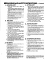
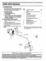
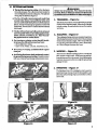
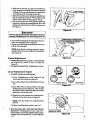
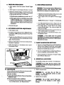
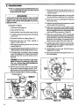
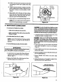
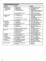
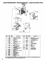
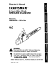
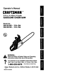
i
operator's
manual
MODEL NO.
358.798141-28,0ce
•Always Wear Eye Protection During Operation
,_E/A/,qS[I:RRFT$MRN®_
GAS WEEDWACKER
2 Cycle Engine
AWARNING:
ReadtheOperator'sManual
* Assembly
and Follow All Warnings
and Safety Instructions.
• Operation
®
Fuel Mix 16:1
* Maintenance
• Repair Parts
FailureTo Do So CanResuIt
in SeriousInjm-y.
um
i
Sold
by
iii iiii
66909-2-16987-1-17387
Sears,
ilnf11 if
iiii
Roebuck
,i, i_11
and
Co.,
Chk:ago,
Ill. 60684
U.S.A.
, ,i,,,i,,i
@Sears, Roebuck and Co., 1987
_:
TWO YEAR LIMITI_
WARRANTY ON CRAFISMAN
WEEDWACKgR®
For Two years fromdateofpurchase, when_Weedwacker_is
mainlained,luhricated,andtunedup_.eordingtotheoperating
ann mamtenaw.e mstmclaons m tlae operators manual, Sears will repair free of charge any defect in material or worlmmnship.
This warranty excludes nylon line,spark plug,and air cleaner ;which are expendable parts and [_come wornduringnor-
_,_
._
IfthisWeedwacker _ isused forco_ial
or rental purposes, thiswarranty applies for only 30 days from the date ofpurchase.
WARRANTY SERVICEiS AVAILABLE BY COI'_--TING THE NE_
SEARS SERVICE CENTER/DEPARTMENT
IN THE UNITED STATES. This w_rranty appli_ only while this product is in use in the United States.
This warrantygives youspecific legal rights, and you may also have other rights which vary from state to state.
SEARS, ROEBUCK AND CO_DEF£ 6981731A SEARS TOWERCHICAGO, IL 60684
_
TABLE OF CONTENTS
WARNINGS AND SAFEFY INSTRUCTIONS
KNOW YOUR TIRJMMER ..........................
.........
ASSEMBLY
ENGINE INFORMATION
...............
A. Fueling Your Engine
B. Pre-Operation
Cheeks ........................
C. Starting Instructions ..........................
D. Operating Instructions ........................
USING YOUR TRIMMER ..........................
A. Trimmer Safety
.
B. Trimmer Line Advance .......................
C, Cutting Methods ............................
3
6
"
•...........
'
7
9
,9
10
t0
iI
11
12
12
13
GENERAL MAINTENANCE ......................
A. Maintenance Safety ..........................
B. Trimmer Head ..............................
C. Carburetor Adjusm_ents .......................
D. Air Filter ..................................
E. Starter Rope ................................
E Drive Shaft Lubrication ..................
G. Trouble Shooting Chart .......................
REPAIR PAKrlS LIST .............................
ACCESSORIE_ ....................................
A.TTACHMEN'IS .................................
QUICK REFERENCE PAGE .......................
SPECIFICATIONS
ENGINE
TYPE:
2-Cycle, Air-Cooled
DISPLACE'MENT:
28,0c0
ENGINE
Operating-- 6500- 7500
RPM:
Idle-
2800 - 3200
IGNITION:
SolidS_
CARBURETOR:
Diaphragm All Positions with.
adjustable _el mixture jets
ENGINE
"OFF":
PushButton
STARTER:
Auto Rewind
MUFFLER:
Lo Tone _.California approved
spark arresting
_CLUTCH:
FUEL
TANK:
Centrifugal
16,9 ft, oz_
SPARK PLUG:
STD361258
SPARK PLUG GAP:
.025"
MODULE
,010"/ ,014"
AIR GAP:
LL_RICATION:
Gasoline/Oil
DRIVE SHAFT HOUSING
SAFETY INSTRUCTIONS
Mixture-
(See "Fueling
CUTTING
LINE:
SHAFT LENGTH:
16:1
Your Engine")
.080 " Diameter, monofilament
'41"
TRIMMERI_FA_
MANUFACTURED
UNDER ONE OR MORE OF THE FOLLOWING U.S.
PATENTS: 3,'/0g.967; 3,826,068; 3,859.776: 4,035,912; 4.052.789: 4.054,992:
4,067. log; 4.104,797:4.114.269;
4,124.938:
4,1.56,312;
4.156,967; 4,161,820:
4,167.812; 4.269,372; 4.269,675; DES.249.630; DF,S,_$5.764: DES.260.394.
U.S. AND FOREIGN PATENTS PENDING.
2
STARTER ROPE
HANDLE
,.AIR FILTER
14
14
14
16
17
18
: .... 19
20
2I
25
25
27
I
VARNINGS
_WARNING
AND SAFETY
-- _
PO_8
INSTRUCTIONS
I00£ CANBEOANGESOU$!
This tool can cause serious injury or blindness to the operator and others. The warnings and safety instructions in this manual
must be followed to provide reasonable safety and efficiency in using this tool. The operator is responsible for foIlowing the
warnings and instructions in this manual and on the tool. Read the entire Operator's Manual before assembling and using
this tool! Restrict the use ofthis power tool to persons who read, tmderstan d, and follow the warnings and instructions
in this manual and on tl_ tool.
_k DANGER
NEVER USE BLADES
WITH THIS TOOL.
-- THE BLADE CAN COME OFF AND
SERIOUSLY INJURE YOU AND OTHERS.
--
THROWN
THIS TOOLIS DESIGNED FOR
LINE TRIMMER USE ONLY.
A WARNING
THE TRIMMER LINE CAN THROW OBJECTS
VIOLENTLY.
-- YOU CAN BE BLINDED OR INJURED.
-- WEAR EYE AND LEG PROTECTION.
m
WARNING
HAZARD ZONE FOR THROWN
•
AW_G
OBJECTS.
--
THE TRIMMER LINE CAN THROW
OBJECTS VIOLENTLY.
--
OTHERS CAN BE BLINDED OR
INJURED.
•
--
KEEP PEOPLEAND
ANIMALS
,
READ OPERATOR'S MANUAL.
-- FOLLOW ALL WARNINGS
/ _/
AND
INSTRUCTIONS.
- r_ILU.E
TOoOSOCAN
RESULT
IN
OPERATOR'S_
.,.,':°
i TURN
P_:>
".-
WARNINGSAND
SAFETY INSTRUCTIONS
A
1. Always wear a safety face shield or goggles. See
"_,ccessories."
2. Always wear heavy, long pants, boots and gloves. Do
not wear loose clothing, jewelry, short pants, sandals
or go barefoot. Secure hair so it is above shoulder
length.
3. Do not operate this tool when you are tired, ill or under
the influence of ateohol, drugs or medication.
4. Always use the assist handle. See "%ssembly:'
5. Wear hearing protection if you use this tool for more
than 1½ hours perday.
6. Never start or run the engine inside a closed room or
building. Breathing exhaust fumes can kill.
7. Keep handles free ofoil and fuel.
A
700£$AFETY
1. Inspect the entire tool before each use. Replace
damaged parts. Check for fuel leaks and make sure all
fasteners are in place and securely fastened.
2. Replace trimmer head parts that are cracked, chipped
or damaged in any way before using the t_x)l.
3. Useonly Sears flexible, non-metallic, monofdament,
cutting line of the correct diameter. Never use wire,
rope, string, etc.
4. Be sure the shield is properly attached.
5. Use only the specified trimmer head. See "Specifications:' Make sure the trimmer head is properly installed
and fastened. See "'Assembly:"
6. Besure the trimmer head stops turningwhen engine
idles. See "Carburetor Adjustments"
7. Mal_ carburetor adjustments with the drive shaft
housing supported to prevent the trimmer line from
contacting any object.Hold the tool by hand. Do not
use the optional shoulder strap for support.
8. Keep others away when making carburetor adjustments.
9. Useonly accessories or attachments recommendedfor this tool by Sears.
A
F LSAFE
1. Mix and pour fuel outdoors and where there are no
sparks or flames.
2. Use a container approved for fuel.
3. Do not smokeor allow smoking near fuel orthe tool or
while using the tool.
4. Wipe up all fuel spills before starting engine.
5. Move at least 10 feet away from fueling sitebefore starting engine.
ar/T G
.
"
Inspect the area to be cut before each use. Remove
objects (rocks, broken _lass, nails, wire, string, etc.)
which can be thrown or become entangled in the trimmer head.
2. Keep others including children, animals, bystanders
and helpers outside the 60 foot Hazard Zone. Stop the
engine immediately if you are approached.
3. Always keep the engine on the right side ofyour body.
4. Hold the tool firmly with both hands.
5. Keep firm footing and balance. Do not over-reach.
6, Keep the trimmer head belowwaist level.
Z Do not raise the engine above your waist. The trimmer
head can come dangerously close to your body.
8. Keep all parts of your body away from the trimmer head
and muffler when the engine is running.
9. Use only for jobs expla!ned in this manual.
1. Maintain the tool according to recommended procedui'es. Keep the trimmer line at the proper length.
2. Disconnect the spark plug before performing
nance except for carburetor adjustments.
mainte-
3. Make carburetor adjustments with the drive shaft housing supported to prevent the trimmer line from contacting any object.'Hold the tool by hand. Do not use
the optional shoulder strap for support.
4. Keepothersaway whenmakingcarburetoradjustments.
5. Useonly genuine, replacementparts
as recommended
bySears.
A. TSANSP0J GAND
STORAG£.
1. Hand carry the t0ol with the engine stopped, and the
muffler away from your body.
2. Allow the engine to cool, empty the fuel tank. and
secure the tool before storing or transporting in a
vehicle.
3. Empty the fuel tank before storing the tool. It is recommended that the fuel be emptied after each use. If fuel
is left in the tank, store so fuel will not leak.
4. Store the tool so the line lirniter cannot accidentally
cause injury. The tool can be hung by the drive shaft
housing.
5. Store tool out of reach of children.
6. Stop engine before removing fuel cap.
/."
7, Emptythe fuel tartk before storing thetool, ltis recommended that the fuel be emptied after each use. If fuel
is left in the tank, store so fuel will not leak.
8. Store tool and fuel in an area where fuel vapors cannot
reach sparksor open flames from water heaters, electric motors or switches, furnaces, etc.
If situations occur which are not covered in this manual,
use care and goodjudgment.
Contact your Sears Service
Center
if you needassistance.
5
III
r_o
w
it
III
I
A.
IIII II
I
II
IIIII
II Ill I]
I IIII
.
IIIIIIIII
I
II
TRIMMER
YOUR
iiiiiitlttt
I
lit
I
tit it
t tl It
ttl
I
t
INTRODUCTION
Your Trimmer is a versatile product developed for large
lawnsand to make short work ofa-cariety of lawn care tasks
-- trimming, scalping, mowing, and sweeping.
KEY
NO.
1
Special Features Include:
• Antivibe assist handle
• Semi-automatic
line feed head
• 18" cutting path
• Easily Coverts to a Power Blower, Edger orMiniOd/ivator with the special series of optionalinterchangeable
attacinnents. See the '_l_achrnent"
section for more details.
2
3
4
5
6
--
B. UNPACKING
INSTRUCTIONS
I. Remove contents from the carton if you have not
done so_
2. Check parts against the list below.
3. Examine parts for damage. Do not use damaged parts.
4. Notify your Sears Store immediately_tf apart is missing or damaged.
NOTE: It is normal to hear the fuel filter rattle in an empty
fuel tank.
CARTON CONTENTS:
QTY.
Engine
1
Drive Shaft/Boring Assembly w/Safety Label
I
Shield
1
Trirmner Head
1
•Assist Handle
1
8-oz. Can -2 Cycle, Engine Oil
I
Operator's Manual (not shown)
1
Loose Bag Parts ( not shown)
1
* LOOSE PARTS BAG CONTENTS:
7
8
9
10
II
12
Flex Shaft Lube
Bearing Housing Screw
Large Cup Washer, Trimmer Head
Flex Bolt, Assist Handle
Flat Washer, Assist Handle
Knob, Assist Handle
1
4
1
t
1
1
* These hardware parts are Grade 5 or better. Do not substitute
lower grade parts. Always use genuine replacement parts as
recommended by Sears.
SAFETY LABEL
STATE AND LOCAL ORDINANCE
REQUIREMEN_
Yourengine is equipped with a temperature limiting muffler and spark arresting screen which meets the requirements of California
Codes 4442 and 4443 and the requirements of all U.S. Forest Land and the statesof Maine, Oregon, and _shington.
Check with your state and local authorities for regulations pertaining to Temperature Limiting Muffierand Spark Arresting
requirements. If you operate this tool in a state or locale where such regulations mist, you are legally responsible for maintaining
the operating condition of these parts. Failure to do so is a violation of the law.
g,r,,,i
IHII[II[IIIVJIJII
I
III
A.QQi_.]Iu[IIll
•,.v-...-...,,--..,
iiii
IIIIIIIIII
ii
I
II
I
IIIIII
I
.V
_t°°l
is received assembled,
repeat all steps in this'section
and is adjusted for the Ol_mtor.)
I
iiiiiiiiiiii
iiiii i
iii
i iiiiiiii
iiiiiiiii
a. Small Phillips Screwdriver
b. Flathead Screwdriver
c. Needle-nose Pliers
• This Operator's Manual has been developed to help you
assemble the tool and to provide its safe operation. It is
important that yo u read the entire manual to become
familiar with the tool before you begin assembly.
YOUR
OPERATOR'S
d. Tape Measure & Grease Pencil
e. Wrenches: 3/8 inch, 7/16 inch or
Adjustable wrench
MANUAL
"
Iltli_tlltlllI
II IIIIIII
I
Ill[
III
H
IIIIImHI
ii
i
IlililIliilllllI I I I
1. SHIELD
_ Figure
1
Failure to install the shield in the position shown in Ytgm-e
I can result in serious injury to the operator. The shield
must be centered under the b_
housing clamp with
the widest part of the shield directed toward the engine.
[CAI/TION:
] The line limiter is sharp and can
d. Line up the hole in the Dust Cup with the hole in the
Bearing Housing by turning the Dust Cup. Figure 3.
e. Insert the Phillips screwdriver into the aligned holes
to keep the Arbor Shaft from turning. Figure 3.
f. Tighten the Trimmer Head against the Dust Cup
while holding the Phillips screwdriver.
g. Remove the Phillips screwdriver.
Cut you.
a. Align the Stfield on the Bearing Housing with the
Shield centered under the Bearing Housing Clamp
with the widest part of the shield directed toward the
engine. Figure 1. Align screw openings.
b. Insert the four Bearing Housing Screws through the
Bearing Housing and the Shield.
c. Tighten each Screw evenly and securely with a
wrench or flathead screwdriver.
:2.TR/MMER
I
STEPS
A WAR mG
_
is correct
2. Tools you Will need:
k
B. ASSEMBLY
IIII
to be sure assembly
IIII
A. PREPARATION
1. READ
.
,m,l,Wll,_llUll
HEAD
-- Figure
h. Press the Tap Button and pull4 inches of line from
the Trimmer Head. Figure 3. About 2 inches ofline
can be advanced each time the Tap Button is pressed.
NOTE: To remove the Trimmer
Head, insert
Phillips screwdriver into the aligned holes in the Dust
Cup and the Bearing Housing. Unthread the Trimmer Head counterclockwiseA, m_.
2 &3
a. Remove the packing cover from the Arbor Shaft.
b. Place the Large Cup Washer on the Arbor Shaft. Fit
the center opening ofthe Washer around the shoulder
of the Dust Cup. Mal_ sure the Washer is against and
curved over the Dust Cup. Figure 2.
c. Threadthe TnmmerHeadclockwise
_
ontothe
Arbor Shaft.
tL4_RDWARESHOWNACTUALSIZE
BEARING
WIDESTPART
OFSItIELD
/
HOUSING
i
i
iiii
ii iii i._
Figure
3
7
'+ 3. DRIVl_
SHAFT
HOUSING
_ Figure4
.+
a. Removethe packing cover from theend ofthe Drive
Shaft Housing.
, NOLO: Make sure the Flexible Drive Shafl does not
fall out of the Drive Shaft Housing when the packing cover is removed. Dirt on the shaft will
significantly reduce its life. If the Flexible Drive
Shaft falls out of the housing, reinstall.
b. Mark aline 1-1/2inches from the straight end of the
Drive Shaft Housing. Figure 4.
c. Loosen (but do not remove) the Pinch Clamp Bolt
On the Engine Shroud. Figure4.
d. Pull about 6 inches of the Flexible Drive Shaft from
the straight end of the Drive Shaft Housing with
needle-nose pliers.
e. Insert the end of the Flexible Drive Shaft into the
square opening inside the Engine Shroud.
f. Firmly push the Drive Shaft Housing into the Engine
Shroud untilit bottom s out, approximately at the
1-1/2" mark. Figure 4.
g. Position.the Drive Shaft Housing as shown in Figure
5.
h. Tighten the Pinch Clamp Bolt securely with
a wrench.+
NOTE: If the Pinch Clamp Bolt is removed, the Bolt
must be installed into the unthreaded side of the
:PinchClmn p first, then, into the threaded side in
order to securely attach the Drive Shaft Housing.
_1_
_
HANDLE
--Figure
5
a. Hold the Assist Handle so it is leaning back toward
theEngineand
aligned betweenthe Engineandthe
Safety Label.
if
++
b. Firmly push the Assist Handle onto the Drive Shaft
Housing. Figure 5.
c. Install the Assist Handle Bolt, Washer, and Knob.
d. Tighten the Knob by hand only.
&OPERATING
a.
POSITION,-
Figure
6
Before starting the Engine, stand as shown in
Figure 6 and check for the following:
l).Left arm fully extended ,hand holding Assist
Handle.
2).Right arm slightly bent, hand holding+the Rear
" Handle, fingers onThrottle Trigger.
3) .Rear Handle below waist level.
4).Weight of tool evenly distributed
between arms.
5).Without operator bending over, the Trimmer
Head is near and parallel to the ground and easily.
contacts the material to be cut.
b. Adjust the Assist Handle up or down the Drive
Shaft Housing (but above the Safiey Label) to acomfortable position.
FLF_XmLE
DRIVE
INSTALL
. PINCH CLAMP BOLT
SHAFI"
FROM
MARK 1½ _
ENGINE
PINCH CLAMP
+:
4.ASSIST
l).Loosen the Knob by hand, adjust Handle.
Retighten Knob by hand only.
2).Rotate the Handle from left to fight if it is
necessary to tilt the angle of the Trimmer Head
for cutting a large, sloped area such as a ditch
bank.
HOUSING
, Ftgure4
SAFETYFACESHIELD
RIGHT ARM
SLIGHTLY BENT,
HANDLE, FINGERS
LEFT ARM EXTENDED,
HAND HOLDING THE
ASSIST HANDLE
\
WASHER
REARHANDLE
BELOW
WMSTLEVEL
'.
*+,...
....
m
illiillii iiillii •Him
iiiiii
IIIH
,
I I II
iii iiiiii
ENGINE
illl
Illllllllllll
IIIIII
.
Illllllll
INFORMATION
3. USE THE
a. Use only recommended
FOLLOWING
ONLY:
(16 parts gasoline to 1 part oil)
fuel mixtures.
b. Mix and pour fuel outdoors and where there are
• no sparks or flames.
c. Use a container approved for fuel.
;d. Do not smoke or allow smoking near fuel or the
tool or while using the tool.
e. Wipe up all fuel spills before starting engine.
f. Move at least 10 feet away from fueling site before
starting engine.
g. Stop engine before removing
fuel cap.
,t.no NoT USE:
h. Empty thefuel tank before storing the tool. It is
, recommended that the fuel tar& be emptied after •
each use. If fuel is left in tank, store so fuel will not
leak.
i. Store tool and fuel in an area where fuel vapors
cannot reach sparks or open flames from water
heaters, electric motors or switches, furnaces, etc.
• BIA oIL (Boating Institute of America) --- Does not have proper additives for air-cooled
2-cycle engines and can cause damage to your
unit.
"
• AUTOMOTIVE OIL- Does not have proper additives for 2-cycle engines
and can cause damage.
• GASOLINECONTAINING
High Test, Premium
Methanol)
2. FUEL
MIXTURE
• Your tool is powered by a two-cycle engine which
requires a fuel mixture of regular unleaded
• gasoline and a high quality engine oil specially
•made far 2-cycle, air cooled engines. The internal
design of the 2-cycle engine requires lubrication of
moving parts. Lubrication is provided when the
recommended mixture of gasoline and oil is used.
Gasoline must be clean and not over two months
old. Gasoline will chemically break down and form
compounds that cause hard starting and damage in
2-cycle engines.
• The correct measure of gasoline to oil is very
important. Too much oil in the mixture will fou! the
spark plug.
AI_OHOL
or Gasohol
--
(Ethanol
or
-- Stiffenscritic'_ carburetor fuelmetering elements
and causes engine damage from overheating.
-- Increases vapor lock (causes hard starting).
Attracts water causing corrosion damage.
5.HOW
TOMIX
FUEL AND
FILL TANK
a. Pourl/2 gallon regular unleaded gasoline into an
approved, markedconminer.Do
not mix gasoline
and oil directly b7 the fi_el tank.
b. Add entire measureofengine
oil.
c. Cover container tightly and shake for one minute.
d. Add remainder
of gasoline.
e. Cover container tightly and shake again.
] CAUTION:[ Too little oil or incorrect
cause the engine to overheat and seize.
oil will
f. Slowly remove fuel container cover.
g. Remove fuel cap. See "'Specifications:" for location,
Always mix the fuel thoroughly in a container
since gasoline and oil do notreadily combine. Do not
mix gasoline and oil directly in the fuel tank.
h. Fill the tank using a spout or funnel.
i. Reinstall the fuel cap securely,.
9
I
B.
IIIIIIllll
II
I
PRE_PERATION
• i iiiiiiiiiiiiiii
iii
Illt
l
,HlUIlUUlII,U
CHECKS
.
_WARNING
Review all Warnings and Safety
manual.
Instructions
in this
,
Before operating your tool, always:
I. Inspect the entire tool before each use. Replace
damaged parts. Check for fuel leaks and make sure all
fasteners are in place and securely fastened.
7.
2. Replace trimmer head parts that are cracked,
chipped or damaged before using this tool.
8.
3. Use only Sears flexible, non-metallk, monof'flament
trimming line of the Correct diameter. Never use
9.
wire, rope, string, etc.
4. Use only with the shield properly attached.
II I
€.
_
_
£
STARTING
Illl
Illllllllllll
INSTRUCTIONS
10.
(For location
Illlllllllllllllllll
of controls,
I
I
for air filter location.
I
]111111111111111111111
II I
3.
--
For a
Warm Engine:
N(II'E: If engine does not run after 5 pulls, it is
probablyflooded. Wait a few minutes and repeatprocedure using no-chokeposition.
Figure 10.
2. For a Cold Engine:
a. Pull Choketo full-chokeposition.
Figure 8.
b. Grip rear handle and _
Throttle Trigger fully
squeezed through step "f."
•c. Pull Starter Rope sharply until engine pops or
attempts to run, but no more than 8 pulls at fi_ choke
to avoid flooding the engine. The engine "pop" or
'hltempts to run" may be hard to hear. _w operator
mustU_n carefully. After 8pulis, proceed to step
"d." even if enginehas not attempted to run.
•d. Push Choke.to half-choke position. Figure 9.
e, Pull Starter Rope sharply until engine runs, but no
more than 5 pulis,
4.
For a Warm
Engine
(After
Running
out
of IAter):
a. Refuelengine. Move 10 feetaway from fueling site.
b. Pull Choke to full-choke position. Figure 8.
c. Grip rear handle and keep Throttle Trigger fully
squeezxxl until engine runs.
d. Pull Starter Rope sharply until engine pops or
attempts to run, but no more than 5 pulis.
e. Push Choke to no-choke position. Figure 10.
f. Pull StarterRope until engine rum, but no moi_than
5 pulls. Keep Trigger fully squeezed untilengine
runs smoothly.
NOFE: If engine has not starteA after 5 pulls, repeat
steps "a" through "e."
f. Allow engine to nm 5 seconds, then push Choke to
no-choke position. Figure 10. Keep Trigger fully
squeezed until engine runs smoothly.
NOTE: If engine has not started, pu!l Starter Rope
5 more pulls. If engine still does not rtm, it is probably flooded. Wait a few minutes and repeat procedure using no-choke position. Figure I0.
NOTE: If engine dies with Choice at no-choke
position, repeat steps "d" through "f"
1
!
FULL CHOKg.
t
HALFCHOKE
t
_1 ........
7
IIIIIII
[
a. Pull Choke to half-choke position. Figure 9.
b. Grip rear handle and keep Throttle Trigger fully
squeezed until engine runs.
e. Pull Starter Rope sharply until engine runs, but no
more than 5 pulls.
d. Push Choke to no-choke position. Figure 10.Keep
Trigger fully squeezed until engine runs smoothly.
c. Stand Lu the operating position. Rest Shield on
ground, supporting Trimmer Head up off ground
away from tr_s, bushes, onlookers, etc. Figure 7.
d. With optional Shoulder Strap, place Shoulder Strap
on your shoulder. Start engine before clipping
Shoulder Strap to the tool.
Lo
IIIIII
refer to "Specifs_tions.")
AW_G
AWAmCm
POSITION
IIII
Avoid any bodily contact with the muffler on a warm
engine. A hot muffler can cause serious burns.
The trimmer head will turn as soon as the engine starts.
_G
Make carburetor adjustments with tbe drive shaft
housing supported to prevent the trimmer fine
from contacting any object. Hold the tool by hand.
Do not use the shoulder strap for support.
Keep others away when making
carburetor
adjustments.
Use only accessories or attachments as recommended by Sears for this tool.
Clean the air filter if dirty before operating the tool.
Refer to._'Specificafions,'
I Illlllll I
1. Before
starting
the engine:
a. Fuel engine. Move 10 feet away from fueling site.
b. Extend line4 inches from the Trimmer Head k)provide and adequate load on the engine.
[
Use only the specified trimmer head. See "Specifications?' Make sure the trimmer head is properly
installed and securely fastened, Refer to "Assembly"
Be sure the Wimmer head stops turning when engine
idles. See "Carburetor AdjustmentsY
Figures
'igure 9
NOCHOKE
_
HHH,
Figure 1o
(
r
I IIIIIIH
III
D.
III
OPERATING
1 II IIII
I IIIIIIIIIIWII
I
III
,,,m
IIIIIIIIIIIII
III
INSTRUCTIONS
ii
11 IIII[
."
t. Bring the engine to cutting speed before entering
the material to be cut.
a. Do not run the engine at a higher speed than
•necessary. 1_e cutting line will cut efficiently when
the engine is run at less than full throttle. At lower
speeds, there is less engine noise and vibration. The
'trimmer line will last longer and will be less likely
to "'weld" on the spool.
3. Make sure the Trimmer Head stops turning when
the Throttle Trigger is released and the engine runs
at idle speed. For correction, refer to "Carburetor
Adjustments"
4. To stop the engine:
a. Release the Throttle Trigger.
b. Push"Off" Button. HoM button down until the
engine stops. Figure 11.
L
b. If the Trimmer
L*.r
Head does not turn when the
engine is accelerated, make sure the Drive Shaft
• Housing is properly seated in the Engine Shroud.
Refer to '_ssembly-Drive
Shaft Housing:'
2. Always releas e the Throttle Trigger and allow the
engine to return to idle speed when not cutting.
I IIIIII
I IIIIIIIII
I
IIIIII
Flgu¢_
ii
IIII
ilU
11
iiiiiiiiiiiiiiiiiiiiiii iii
iiiiiiiiiiiiiiiiii
USING YOUR TRIMMERI
IIIII
IIIIIIIIIII
I IIIIIII
I IIII
III
i Illllll II
AV0'ARNING
II
_
=
, II III _
[
II
I
I
" .THROW$OBJEL
The rapidly moving line causes objects to be thrown violently.
The shield will notprovidecompletepmtecfion
to the operator
or others. The operator must wear a safety face sMeld or
goggles. Always wear heavy, long pants andbo0ts. Keep
others at least 30 feet away.
: .
.'"
AWARN•ING
f
"
.
HAZASDZONE
This tool will throw objects and Cut. Keep others including
children, animals, bystanders and helpers at least 39 feet
away from the operator and tool. Stop the engine if yon are
approached.
WARNING
Trimmer Head
#71-85764
Use Only Genuine Replacement
,-
TZlM
Trimmer head parts that are chipped, cracked or damaged in
any way, can fly apart and cause serious injury. Do not use.
Replacedamaged
parts before us'mg the tool.
Parts
_/
A. _'rRIMMEIg
$_
1. OF A OR
..- - a. Always wear asafety face shield or goggles. See
'_.ccessories,'
f. Make carburetor adjustments with the drive
shaft housing supported to prevent the trimmer
line from contacting any object. Hold the tool
with your hand. Do not use the optional shoulder
strap for support.
b. Always wear heavy, long pant_ boots and gloves.
Do not wear loose clothing, jewelry, short pants, sandais or go barefoot. Secure hair so it is above
shoulder length.
c. Donot operatethistool
under the influence
medication.
whenyouare
of alcohol,
g. Keep others
adjustments.
tired, ill or
drugs or
free of oil and fuel.
a. Inspect the area to be cut before each use. Remove
objects (rocks, broken glass, nails, wire, string, etc,)
which can be thrown or become entangled in the
trimmer head.
•
2. TOOL
b. Ai_vays keep the engine on the right side 0fyour
body.
a. Inspec t the entireto01 before each use. Replace
damaged parts. Check for fuel leaks randmake sure
all fasteners are in place and securely fastened.
c. Hold the tool fLrmly with both hands.
d. Keep firm footingand balance. Do not over-reach.
b. Use only Sears flexible, non-metallic, monofila* merit cuttingline of the correct diameter. Never
use wire, string, rope, etc.
e. Keep the trimmer head below _aist level.
f. Do not raise the engine above your waist.
'c. Be sure the shield is properly attached.
g. Keepallp_tsofyour
bodyaway from thetrimmer lineand muffler when the engine is running.
d l Make sure the trimmer head is properly installed
and securely fastened. Refer to "Assembly."
....
h. Use only forjobs
e. Be sure the trimmer head stops turning when the
"
:'_e
I
idles. See "Carbu._r_r
II
K _
_
IIII I' IIIIIIIII
I
recom-
3._G
ever start or run the engine lnstde a dosed room
or building. Breathing exhaust fumes can kill.
f. Keep handles
\
making carburetor
h. Use only accessories or attachments
mended for this tool by Sears.
d. Do not swing the toolwith Such force that you are
in danger of losing your balance.
e.
away when
s
ex_.Jained
in this
manual.
Adjustments."
I I
ADVANCE
• The line will advance approximately 2 inches each
time the bottom of the trimmer head is tapped on the
ground with the engine running at full throttle.
• TheLnSmtefficient line length is the maximum length
allowed by the line limiter.
• Alwayskeepthesmeldinplacewhenthetoolisbeing
olmrated.
JJl
Ill
II
iiiiii
I
Ill
IIIIIII
IIIIII I
"I'II'II'IH
II
I
Useonly Sears flexible, non-metallic monofdamentcuttingline. Donot use other materials suchasrope,
wire,
string, etc. W'we can break off during cutting and
• become a dangerous mile.
t
&wamema
NOLO: Always tap the trimmer head on a grassy area. Tapping
on surfaces such as concrete or asphalt can cause excessive wear
to the trimmer head.
• To advance line:
1. Operate the engine at full thi'ottle.
2. Hold trimmer headparallel
ai'ea.
to and above the grassy
N_
\
..•-
LINE LIMITER
•
I
LINE,
\ t
I
TAP BOTTOM OF
TRIMMER HEAD
3. Tapthe bottom of the trimmer head lightly on the
groundonetime. See Figure 12. Approximately 2
inches of line will be advanced with each tap.
NOTE: ffthe line is worn down to two inches or
less, more than one tap will beVWxluir_ to obtain the
most efficient line length.
12
TOADVANCE
_
/•.
Figure
12
_L
i iiiiiiii
-
C. CUTTING
I
IlllIIIII
III
II
METHODS
• The tip of the line does the cutting. Allow the line to
trim at its own pace. You will achieve better results by
.... not eroding the line into the cutting area. The right and
wrong way are shown in Figure/3.
• The line will easily remove grass and weeds from
around walls, fences, trees and flower beds, but it
also can cut the tender bark of trees or shrubs and scar
fenceA To help avoid damage to vegetationor trees with
tender bark, shorten line to 4-5 inches and use tess than
full throttle.
Always wear eye protection. Never lean over the trimmet head. Rocksor debriscan ricochet orbethrmm into
eyes and face and cause blindness or other serious injury.
1.
TRIMMING
,-. Figure
14
Hold the tap button about 3 inches above the ground and
tilt thetrimmer head atan angle. Allowthe tip oft.he line
todothe cutting. Do not force the trimmer line into the
workarea.
• The line will wear faster and willneedto be advanced
• more ti_uenfly whenyou are cutting against rocks,
bricks, concrete, metal fences, etc., than when cutring against trees or wooden fences.
2. SCALPING -- Figure 15
•The scalping technique removes unwanted vegetation.
Hold the tap button about 3 inches above the ground and
tilt the trimmer head at an angle° Allow the tip of the line
to strike the ground around trees, posts, monuments,
etc. This technique increases line wear.
• For trimmingor scalping, use less than full throttle
to increase line life and decrease head wear.
-- during light duty cutting.
--next to rocks, bricks, concrete, metal fences, etc..
e-Formowingorsweeping,
clean job.
_
use full throttle for a good
3.
MOWING
-- Figure
Yo_artrimmer is ideal
lawn mowers cannot
keep the line parallel
head into the ground
..damage the tool.
• Avoid letting the trimmer head continuomly contact
the ground during normal cutting. Constant contact
will causetrimmer head damage and premature wear.
4.
SWEEPING
16
formowing in places conventional
reach. In the mowing position,
tothe ground, Avoid pressing the
as this _:an scalp the ground and
-- Figure
17
The fanning action of the rotating line can beused for
a quick and easy clean up. Keep the line paxallei to and
above the surfaces being swept and move the tool from
side to side.
Figure
13
14
Figure
15
Figure
16
Figure 17 ....
....
i3
III
I
GENERAL
I
I
iiiiiiiiiiiiiiiiiiiiiiiiii
A. M_.JNTENANCE
iii
II Ill
3. Makecarburetor adjustments with the driveshaft
housing supported to prevent the trimmerline
from contacting any object. Hold the tool with your
hand. Do not use the optional shoulder strap for
support.
TRIMMER
HEAD
Spool
when
making
carburetor
III
idles. See "Carburetor Adjustments:'
.
Use only Sears flexible, non-metallic monofilament
cutting lineofthecorrect
diameter, Never use wire,
rope, string, etc.
7. Replace trimmer head parts that are cracked, chipped or damaged in any way before using the tool.
8. Use only genuine
mended by Sears.
replacement
9. Inspect entire tool. Replace damaged parts. Check for
fuel leaks. Make sure all fasteners are in place and
securely fastened.
i
i,,
ii
i
/
w/Line
Figure
TAP Bt,TFON
L(K'K RING _._
HOUSING
Figure
Aw _smsv
&w,tmmm
18
DRIVI
Trimmer head paris that are chipped, cracked or
damaged in any way can fly apart and cause serious
injury. Do not use. Replace damaged parts before
using the tool.
NOTE: After a groove is worn into one side of the aluminum
line saver, the line saver can be turned upside down and
reinstalled (with the spool removed) to provide a new wear
surface. Figures 19 & 20.
19
.._CATCtl
LINE
:
The line saver must be installed only from the inside of the
spool housing with the flanges facing toward the spool, If
installed on the outside of the spool housing, the line saver
can fly offand become a dangerous missile.
14
parts as recom-
+
a. Hold the Trimmer Head as shown inFigure 18.Press
the lock tab, and turn lock ring counterclock• wise _.
b. Remove the lock ring, tap button, and spool. Figure 19.
c. Clean dirt and debris from all parts.
:d. Inspect all trimmer head parts. Clean and replace as
necessary. See "Spool Replacement" this section.
l
Illll
5. Be sure thetrimmer head stops turning when engine
• For proper line feed:
.. Use only genuine Sears pre-wound spools and
bulk line, Use of other spools or line can result in
excessive breakage, line welding and improper line
feed.
-- Pre-wound spools offer the most convenient
melhod for replacing line as well as opt_umperformance. Be sure to always replace thespool, ffthe
square comers of the drive lugs are rounded off,
• reduced in size or broken off. Figure23.
• • Alwaysdean dirt anddebris from thespool andhub
when performing any type maintenance.
1. Installing
I
(
i
B.
III
SAFETY
2. Disconnect
the spark plug before performing
maintenance except for carburetor adjustments.
away
II
II IIIIIIIIII
Maintain the tool accordingto recommended procedures. Keep the trimmerline at the proper length.
4. Keep others
adjustments.
I IIllIl
MAINTENANCE
ill
l.
III
Figure
20
,
e. Make sure the line saver is in place and installed correctly. Insert the end ofthe line in the line saver as shown
in Figure 20. Place spool in homing. Press spool down.
"lhm and lock spool under lugs on drive gear.
f. Replacethe tap butch; press lock tab and installthelock
ring. Tumloekringcloclcwise
_
and fasten under
all four catches on the housing. Figures 20 & 21.
g. Check to be sure the lock ring is properly installed by
att_,m_ting to turn thering cotmtereloekwise _
and
pulling emit. Reinstall properly ifthe leek ring comes
Off. Figure 21.
TURN LOCK RING
CLOC_
TOINSTALL
FigUre
Zl
_WARNING
The lock ringmust be fastened under all four catches on
housing. If installed incorrectly, the lock ring am fly off.
.A2PROXIMATELY 2 INCHES OF LINE
CAN BE PULLED FROM THE TRIMMER HEAD
h. _all on the line to change the spool from theIocked position tothe operating position. Figure 22.
i. Obtain correct line length by pressing tap button and
pulling on the line again.
NOTE: Each time the tap button is pressed, approximately 2 inches ofline can be pulled from the trimmer
head. Figure 22.
"--.Spool
F_mre 22
Replacement
a. Replace the spool when the squa_ comers of the lugs
are rounded off, reduced in size, or broken off.
Figure 23.
b. To replace the spool, follow "Installing Spool wiLineY
3.Line
Replacement/Repair
a. To replace the line on existing spool:
: 1.) Follow "Installing Spool w/Line;' steps "a-d,' and
remove any line re_g
on the spool.
LUG
2.)Use a40 foot length of Sears .080_diameter trimmer
line.
NO!_L
WORN SI'OOL
SPOOL
F mre 23
3. ) Insert 1/16 to 1/8 inch of the end of the Iine through
the hole in the inner rim ofthe spool. Allow no more
than 1/8 inch of line to extendbeyondtherimto
avoid
interference with the drive gear.
4).Wrap the line evenly onto spool in a clockwise direction as shown by arrow on spool. Figure 24.
NOTE: Wrap line fmnly
line feed.
5.)Follow
:
"Installing
and evenly for proper
Spool wtLine"
steps "e--i."
b. if the line breaks off or back up in the Trimmer
Head, follow "Installing Spool w/Line,' steps "aM:'
Pull slaekinline untilthelineis tightly _mmndon spool,
Ieaving4-6inches ofextendedIine. Continuewithsteps
"e-iY
WRAP
LINE ON SPOOL
AS SHOWN BY ARROW.
•
.1/8"
l
_t
Figure2,4
15
I
I
€.
I
IIII IIIIIIIIII
IIIII
III
IIII
CARBURETOR
IIIIII
II
i
making
IIIIl JIlllI
II
a. Use a fresh fuel mix. See "Fueling Your Engine"
Make carburetor adjustments with the drive shaft housingsupportedtopreventthetrimmer
line from contacting any object. Hold the tool with your hand. Do not use
the optional shoulder strap for support.
AW_G
away when
iillii
1. PREPARA'I_ON
ADJUSTMENTS
AWARNING
Keep others
adjustments.
iUlllJmJll
b. Make sure the line extends to the length allowed by
the line limiter to provide correct load on engine.
C-
carburetor
d.
Aw asm
Serious injury to the operator and others can occur if the
carburetor is not properly adjusted.
Start the engine. Cut grass for 3 minutes to warm
en(me. 7he engine must be at operan'ng temperature
before carburetor adjustments can be performed
correcll_
Stopengine and remove air filterby pulling itoutwith
your fingers. Refer to "Specifications" for location.
2. IDLE SPEED
a,
ADJUSTMENT
Allow engine to idle.
b. Adjust Idle SpeedScrew (Figure 25) until the engine
• The carburetor has been carefully adjusted at the
• factory. However, the operator must be sure that
adjustments are made when any of the following
conditions occur:
NOTE: Be sure to properly prepare the• toolas
deseribedin "1. Preparation" before making any adjust• ments.
-- Engine will not continue to run at idle position.
See "2. idle Speed Adjustment"
and "5. Lmv
Speed Mixture Adjustment."
-- Trimmer Head continpes to spin when the engine
idles. See "2. Idle Speed Adjustment"
and "4.
Deceleration Check"
-- Engine dies or hesitates when it should accelerate.
See "3. Acceleration Check"
-- Loss of cutting power which cannot be corrected by
cleaning the air filter. See "tt I_gh Speed Mixture
Adjustment"
-- Engine does not return to idle from full throttle
• within 2 s_onds. See'_4. Deceleration Check"
--Engine
will not run. See "Troubling Shooting
Chart" Then, if the carburetor requires adjustment, begin with "7. Basic Carburetor Settings"
• This is a complicated task and it is important
follow instructions in sequence as indicated.
to
• Very Small adjustments can affect engine performance. It is important to turn the screw a very small
amount per adjustment and test performance before
making further adjustments. Each adjustment should
be no more than the width of the slot in the adjusting
screw.
_k WAdtt_G
The trimmer line will be spinning during most of this
procedm_ Wear your protective equipment ando_e
all safety instructions.
continues to run without stalling and without the
trimmer head moving.
-- Turn screw clockwise _
to increase engine
speed if the engine stalls or dies.
-- Turn screw counterclockwise
&-_ to slow
engine down andiorto keep the trbnmer linefrom
turning.
c. Follow instructions in "3. Acceleration Check" and
'_,. Deceleration Check."
d. No further adjustments are necessary ifthetrimmer head does not turn at idle speed and if performance is satisfactory.
_WARNING
Recheck idle speed after each adjustment. The trimmer
head must not turn at idle speed to avoid serious injury
to the operator and others.
3.ACCELERATION
CHECK
a. Allow engine to idle.
b. Squeeze Trigger fuliy.
1.) Ifperformance is satisfactory,
Deceleration Check"
proceed to '4.
2.) If the engine does not accelerate smoothly, turn
the Low Speed Mixture Screw (Figure 25)
counterclockwise
_,_
a small amount (no
more than the width of the slot in the adjusting
screw).
c. P-_eat step "'b." until smooth acceleration is
obtained.
NOTE: It may be necessary to repeat "2. Idle Speed
Adjustment" through "3. Acceleration Check" to
• obtain correct adjustments.
d. Follow instructions
in "4. Deceleration Check"
f
4.
DEmEan
&TION
CHECK
6.
a. Allow engine to idle, then squeeze Throttle
fully.
Trigger
ICAUTZON: 1 Do not operate engine at full throttle for
prolonged
periods
while making
high speed
adjustments as damage to the engine can occur.
/
b. Allow engine to run at full speed for about I second.
\,.
c. Release the Throttle Trigger to the idle position and
listen to the deceleration of the engine. It must return
to idle smoothly and within 1 to 2 seconds.
a. Support the drive shaft housing offthe ground so the
trimmer line will not contact any object.
b. Allow engine to idle, then squeeze Throttle Trigger
1.)Ifperfonnam:e issatisfactory, proceed to step "d:'
fully.
2. )If the engine slowly or erratically returns to idle
or idles erratically, repeat "2. Idle Speed Adjustment" or continue through Low Speed Mixture and
High Speed Mixture Adjustments to obtain proper
deceleration.
NOTE. Perform steps c. through
ADJUS
a. Allow engine to idle.
b. Tumthe Low Speed Mixture Screw 0Figme 25) slow: ly clockwise _
until the speed starts to drop. Note
this position.
ICAUTION:I
If the engine does not operate
according to these instructions after repeating the
adjusting steps, do not use the tool. Take it to your
Sears Service Center.
c. Turn the Low Speed Mixture Screwcounterclockwise
until the speed increases and then stm'tsto drop
again. Note this position.
d.
e.
Set the Low Speed Mixture Screwat the mid-point between the two positions.
7. nASmCAnSUnETORS rmGS
Follow instructions in "3. Acceleration Check" and '_€.
Deceleration Check?'
A /1
ADJU]ksrJtErCr
SCREW_
_JF/dn/"Yl
•a. Turn the Low Speed Mixture Screw and the HighSpeed
Mixture Screw (Figure 25) clockwise _
just until
they stop. Do not turn the screws until they are O'ghtas
damage to the needle seats can occur.
i
b. Turn the Low Speed Mixtureand High Speed Mixture
Screws one full turn counterclockwise ,i,-_.
!
L
' IDLE SPEED
e. at fuU throttle.
c. Turn High Speed Mixture Screw _igure 25) very
slowly clockwise _
until engine speed is reduced.
d. Turn High Speed Mixture Screw very slowly
counterclockwise
_.
Stop when the engine just
begins to run rough.
e. Turn the screw slowly the minimum amotmt clockwise
until the engine runs smoothly.
f. Follow instructions in "3. Acceleration Check" and 4.
Deceleration Check"
d. Recheck idle speed.
& ••.towsPnnMJx ,jn
HIGH SPEED MIXTURE
c. Follow instruetions"l. Preparation," through "6. High
Speed Mixture Adjustment,'
[
/
_AH_GH SPEED
MIXTUR
E
;juSTMENT
8.
REINSTALL
AIR FILTER
Be sure filter is clean. See "_dr Filter" for instructions.
ICAUTION:[ Fit air filter into the comers of the
housing tokeep dirt from entering the engine and causing enginedamage.
ii
D. &iR
iii
HIIIIIIHI IIHII
III
I I
FILTER
.
A dirty air filterdecreases the life and performance ofthe
engine and increases fuel consumption.
Clean the Air Filter:
1
•
• Always after $ tanks of fuel or 5 hours of operation,
whichever is less.
• More frequently,
in dusty conditions.
1. Pull the Air Filter from the engine with you fingers.
For Air Filter location, see "Specifications:'
1111111111111111111111111
Wash in soap and water.
ICAUTION: I Do
not clean
the air
gasoline
or other flammable
solvent
creating a fire hazard,
3.
filter in
to avoid
Squeeze dry and replace.
[¢_,UTION:I The air filter must be fitted into
the corners of the housing to avoid engine
damage.
17
E. STARTER ROPE
-
• This is a complicated andpotenfially hazardous task.
It is recommended that only your Sears Service
Center perform this repair.
ll. Move away from the fuel tank with the rope to be
installed. Use a match and melt both endsofthe rope
to prevent fraying.
_2_
_WARNING
Always wear eye protection and gloves when servicing
the starter rope. The recoil sprin_ located beneath the
pulley, is under tension. If the spring flies out, serious
injury can result.
13. Insert one end of the rope through the handle and
secure with a knot.
14. Insert the free end ofthe rope through rope exit hole
into the inside of the fan housing.
O To repair or rephce:
Guide rope inside pulley, then up through the pulley
ratchet side of pulley hole to the outside by pushing
the rope through from the hole on the spring cam side
with a small Phillips screwdriver. Figure 28.
1. Disconnect sparkplug wire.
2. Drain all fuel from tank.
3. Remove the four screws from fan housing. Figure 26.
16. Wrap rope counterelockwise
4. Carefully separate fan housing from shroud about
ratchet
comes
fiat on
extend
• one (1)/inch.
5_ Disconnect fuel line from fitting. Figure 26.
6.
Disconnect
Pull the melted ends through a thick, clean rag while
the rope is still hot to obtain smooth, pointed tips.
lead from "'off" button terminal on
ignition module. Figure 26.
_
around pulley
and tuck loose end back under rope where it
out ofhole. Leave a 1/4 to 1/2 inch tail laying
the top of the pulley. The rope tail must not
beyond the edge of the pulley. Figure 28.
7. Slide high tension lead grommet from slot in fan
housing. Figure 26.
17. Carefully replace pulley in the housing. Be sure the
pulley is all the way down. Replace washer and screw
and tighten. Figures 27 & 28.
8. Separate the fan housing completely from theshroud
while guiding the choke throughthe fan housing.
18. Turn the pulley clockwise
wrapped onto the pulley.
9. If the starter rope is not broken, release the spring
tension by pulling about 12 inches of rope from the
pulley and catch the rope in the notch as shown.
19. Putlouttheropebythehandle(approximately
and hold the pulley.
-. " Figure29.
_
until all the rope is
12")
•
[¢_U_ON:
[ Be sure the tension on the starter
spring is released by rotating the pulley clockwise _
withyourfingerwhflepushingdown
on the pulley with your hand.
10. Remove screw and washer from the starter pulley
very carefully. Rotate the pulley clockwise
until no tension is felt and carefi_y lift the pulley out
of the fan housing. Figure 27. Remove old rope.
NOIL_
PULLEY
II
.ROPE
PULLEY
SCREW
lc_moN Momaa_
N
OFFBUTION
TERMINAL
HIGH TENSION LEAD
Ftgu_
27
UNDERSIDE
HOLE
I,
ROPE TAIL
SPITING
RATCHET
FUEL LINE
SHROI_
FUEL LINE FITTING
rWmre
18
FAN
HOUSING
Figure
28
20. Pull thel2 inch slack in the rope into the inside ofthe
fan housing and catch rope in pulley notch. Figure29.
21. Hold the rope taut andmake 2 complete on'as ofthe
pulley counterclockwise _
to placetension on
the spring. Continue to hold the pulley to retain
tension.
22. Align
slack
extent
a!low
pulley notch with rope exit hole, release
in the rope and pull starter handleto the full
of the rope. Release the pulley and slowly
the rope to wind around the pulley.
23. Reverse steps tore-assemble
fan housing to shroud.
NOTE: Be sure to guide choke knob through
the
hole in the fan housing during re-assembly.
--
II
ii tl
i
i
H III
Fignlt_
IIIII
E
DRIVE
SHAFT
• Lubricate
III
I
II
11911
I
II
LUBRICATION
the Flexible Drive Shaft:
-- After each ten (I0) hours of operation.
-- Before operating if the unit has been stored for
:
29
II
90 days or longer.
• Use Flex Shaft Lube Part No. 30102.
NOTE: A tube of "Flex Shaft Lube" has been supplied
with your unit to be used after the fast I0 hours of
operation.
• Use the following procedure
for best results:
AW_G
If engine hasjust beenoperated, avoid toudah_ the muftier. A hot muffler can cause serious burns.
I. Loosen (but do not remove) the.Clamp Bolt and
remove the Drive Shaft Housing from the Engine
Shroud. Figure 4:
2. Remove the Flexible Drive Shaft from the Drive
ShaftHousing as shown in Figure 30.
[ CAUTION: ] Lay the Flexible Drive Shaft on a clean
surface. Avoid laying the shaft on the floor, ground or
on any surface that may have dirt or debris, Even after
wiping theshaft, grease residue can pick up dirt partides that can cause damage or premature failure.
3. Check the Flexible Drive Shaft for broken wires, twists
or kinks and replace if damage is found.
ICAUTION: ] Take care to avoid injuring your hands
and f'mgers with broken wires when checking for
damageorwiping
the flexible drive shaft. A cloth will
not prevent the broken wires from puncturing or tearing your skin.
4. Using a clean cloth, wipe the surface of the Flexible
Drive Shaft thoroughly to remove any old grease.
Figure 31.
5. Applyaurtiformcoat oflubetotheentire
Flexible Drive Shaft.
surfaceofthe
6. Injectthe remaining contcnts ofthe tube into the top of
the Drive Shaft Housing.
Z Replace
Flexible
Drive
Shaft in the Drive Shaft
Housing.
8. Follow theinstructions in '_Lssembly" to replace Drive
Shaft Housing into the Engine Shroud.
WIPETHE _OF
THE FLEXIBLEDRIVE SHA_Pr
Figure
30
Figure
31
19
•
G. TROUBLE
SHOOTING
TROUBLE
CHAKT
CAUSE
REMEDY
..
.+._.
......
/
i i ,H i i
I
Engine wil! not start
or will run only for
a few seconds after
1.
2.
3.
4.
starting
1. Fill tank with correct fuel mixture,
Fuel tank empty.
Engine flooded.
Sparkplug not fa'mg.
Fuel not reaching carburetor.
2. See "Startinglnstructions"
3. Install new plug.
4. Check for dirty fuel filter; clean. Check
for kinked or split fuel linei repair or
replace,
5. See "Carburetor Adjustments,"
6. Contact your Sears Service Center,
5, Carburetor requires adjustment.
6. None of the above.
, ,,,,,, ,,,
I. Idle speed set too stow.
Engine will not idle
properly
3, Low Speed mixture requires adjustments.
4. None of the above.
1. Adjust idle speed screw clockwise to
increase speed.
2, Adjust idle speed screw counterclockwise tOreduce speed.
3. See "Carburetor Adjustments."
4,_Contact your Sears Service Center,
1.
2.
3.
4.
1,
2.
3,
4.
2. Idle speed set too high.
Engine smokes
excessively
Air filter dirty.
Spark plug fouled.
-:
Carburetor requ!res adjustment.
None of the above:
1, Air filter dirty.
2. Fuel mixture incorrect.
3. High speed mixture requires adjustment.
1. Fuel mixture incorrect.
L
Clean or replace air filter.
2. Empty fuel tankand refuel with correct
fuel mixture.
3. See "Carburetor Adjustments:'
1.
2.
3.
4.
2. High speed mixture set too low.
3. Spark p!ug incorrect.
4. None of the above.
Clean or replace air filter.
Clean or replace spark plug and regap.
See "Carburetor _Ajustments"
Contact your Sears Service Center.
See "Fueling Your Unit?'
See "Carburetor Adjustments?'
Replace with correct plug,
Contact yaur Sears Service Center.
I
Unit engagesat
idle speed
1. Carburetor requires adjustment.
2. Clutch requires repair.
Tri.mmerhead
does not turn when
engine is accelerated
, ,,
1, Drive shafi broken or notengaged.
2. Carburetor requires adjustments.
3. Clutch slipping.
..........................
Trim_r head
stops under a load
1. Drive shaft broken or not engaged.
2. Carburetor requires adjustment.
3, Clutc h requires repair,
1
Line does not advance
I II
II
......
1. See "Carburetor._djustments'"
2. Contact your Sears Service Center.
I. Replace or see "Assembly3"
2. See "Carburetor Adjustments?"
3. ,L Contact
your Sears Service Center.
11,,,,
......
1. Replace or See '_ssembly.
2, See "Carburetor Adjustments."
3. Contact your Sears Service Center.
IIIUIIIIII
.........
1. Line improperly wound onto spool.
2. Worn spool.
1. Rewind spool.
2. Replace spool,
.?
2O
III
IIIIIIIII
[
I
ii
WEEDWACKER
® REPAIR
PARTS
LIST -- Model
358.798141-28.0cc
]r l
m
41
l
SE_ImrCl_fS_N.
¢u_ _umwJu=Kim*
....
.q...=..q.._,,
KEY
NO.
•t
PART
NO.
• QTY.
RE(},
706515
1
2
3
4
5
6
7
8
9
t0
11
93896
93898
92O67
92O68
93897
7O6502
93387
92133
93846
92243
I
1
I
1
1
1
1
1
2
12
13
15518
93214
1
1
14
15
16
93886
91783
STD
5I"f007
STD
551225
STD
522510
93853
STD
541410
69O86
1
2
2
17
18
19
20
21
1
DESCRIPTION
_;mm.er Head Assembly 8t0ck
#7! .B5764 (inclo2-9)
Hub wiUne Saver
_"Line Saver
Spring
1
Adaptor*Sp_ing
Drive Gear
Spool w/Line-Stock #71 .,B5789
Reiease Button
Cove_
Shaft-Arbor
Screw-l14".16xl.!18"
Shield
to Bearing Housing
Screw+5tl 6-Self Tapping
Bearing Housing Assemblp
ffncL#15, 16,17,18. 21.22 & 23)
Shield
Retainer-Bearing
Screw #10-24xS/8"-Hex Hd.
Une Limiter
Washer-t14" IntoTooth Lock
1
Screw-Pinch Clamp
Line Limiter
Nut-10-244.ocktng
1
KEY
NO.
22
23
24
26
27
....
PART
NO.
QTY.
REQ,
DESCRIPTION
1
I
1
1
1
Washer-3!8" DustCup
DuSt Cup
Grass Washer
Knob-If4"-20
Washer-ll4-Rat
28
92216
92359
92218
92059
STD
551025
15737
1
Hex Bolt-l14'_-20x1-1 [2"
29
30
31
32
33
34
35
36
37
15561
24376
25985
24373
15209
93859
25986
26009
10754
2
2
2
2
2
1
1
1
I
Screw-Pan Hd,-#12-11x2"
Cup-lsolato_
Spacer Isolator
Isolator.VtbraSon
Wa.sher-l/4 Flat
Handte-Anti_,ibe
Center Section-Handle
Cushi0n-Handlo Center Section
Handle-Anti-vibe
Assembly
(Incl. #29,30. 31, 32, 33.
38
39
4O
41
Decals
101
94493
92261
30102
66909
1
1
1
1
D_ve Sltaft Housing
Rexibte DdveShaft
Rex Shaft Lut:;e
Operator's Manual
26717
27430
26574
1
1
1
Decal-Anti-vibe
Decal-,.°_fatyLabel
Decal.Shield
Beadn_Js& Spacer Kit
2]
SEAR s WACKER
® REPAIR
PARTS
UST
,--.Model
358.798141-28.0€€
15
34102
19 30
35
KEY
NO.
PART
No.
_¥.
" "
v._ ;I.
1
2
3
4
5
6
7
8
9
24436
26566
27373
24365
24371
26679
STD
610807
15412
15583
1
2
10
11
"t5407
15582
1
2
12
13
24461
15357
1
,e,
14
15
16
24407
24303
10729
1
1
1•_
I8
69231
1
RopeKit
19
20
21
22
23
24
26122
10897
69178
42067
26035
15544*
t
1
1
1
1
2
Air BaffldSpacer
FuelPick.UpAssembly
Fan HoustrlgKit
StarterRe_i Spdng
AirBaffle
Screw.#10x3/8" Pan Hd,.. AirBaffle
t
1
1
1
1
1
1
DESCRIPTION •
BumperFuelTank Housing
Handle& FuelTank Housing
HandleCover
Trigger-Throttle
AirFilter
KillSwitchButton
Screw#8-16x3t4"PanHeadHandleCover
Washer
Screw_iO-24xl-1!2"-Sems
FanHousing-Top
Screw
4Screw
#10,.24x518-Same
FanHousing-Bottom
Trigger-Spring
Sorew#'10-14x,314"
*FanHousing
• _toHandle& FuelTank "
KillSwttch Spring
ChokeKncb
FuelCap Assembly(Incl.O.RIng)
KEY
NO,
PART
NO,
QTY.
REQ.
' 25
26
27
26048
15123
15479
1
1
1
30
31
32
34
35
15563*
26981
69247
11778
10776
1
1
1
I
1
36
37
40
41
Decals
101
102
103
15376
93802
15168
26735
2
1
2
1
27456
27406
2.7405
1
1
1
• ._
"
_;
DESCRIPTION
StarterPulley
Washer#10StaxterPulleyScrew
Screw-#lOx3/4".HexWasher
Head-StarterPulley
Screw-#10xl-3!16"Pfastite
' FuelLineFitting•
LineKit
Shroud
FuelTankAssembly
(IncLPI6, 20,31 &32)
.Screw
Bolt.PinchCla_np
Screw
Handle-Starter
Decal-lnstructiotls
Decal-Shroud(Right)
Decal.Shroud(Left)
• If, _our unithasbeenservicedwiththe metalfan housing,usePartNo.15373(screw-#10-24xl/4-RI. Hd.),insteadof.15544(KeyNO.24), and
Part no, 15305(Sorew-#!0.24xi-3/16 Rl, Hd.), insteadof 15563(KeyNo. 30) •
22
SEARS
! VEEDWACKER
® REPAIR
PARTS
LIST -. Model
358.798141-28.0cc
.% -
60..
11- [_! !_-_i
1
,i'
t6 5
9
7
.23
53
5S
I,
KEY
NO.
1
2
•3
4
5
6
7
8
9
10
1!
12
13
14
15
16
17
18
19
20
21
22
23
24
25
26
,27
28
29
3O
31
PART
NO.
QTY.
REQ.
42059.
STD
541131
15127
39114
"'STD
5510_
69181 _
19059
! 536g
10757
1
1
39103
t
1
•2
1
2
4.
I
I
24435 ..1
26237
24558
15254
24651
15004
39082
3943
3933
STD
361258
15126
23373
24902
15404
19111
26581
151_
32029
15351
244_
19108
t
1
1
1
1
1
1
t
1
1
t
1
1
!
1
2
2
2
1
1
DES_iP'RON
"
Spring-Starter Dog
Nut-Rywheei-(5/t6"x26)
Washer-Rywheel
• FlywheelAssembly(incl. #1)
- .Screw #8-32x3i4_-Fil. Hal.Ignition Module
• Kit-Ignition Module '
,_Seal-Crankcase
•Screw.Crankcase
Crankcase Ass'y. (Inc!. #7 & 28
&Qty. 4 of #8)
High Tension-Lead Assembly
(ind.#17.18 & 19)
•Grommet-Plug Wire
.Guide Plate
Choke Shutter
Wave Washer
Choke Wire Clamp
Screw
High Tension Lead Wire
Boot-Spark Plug
Connector-Spark Rug Lead
Spark Plug (CJ-14)
Key-Flywheel
• Boot-Throttle
Throttle Wire(Red)
Screw
"_Gasket-Cyfinde r
Ring-Piston
Retainer-Wrist Pin
Bearing-Ctankc_se
Washer-Thrust-Crankcase
Reed Valve.
• Gasket-Carbu retorCase to
Crankcase
* IndicatesEngineGasketKitContents
KEY
NO.
PART
NO.
.32
33
34
35
36
1
1
1
1
4
38
39
19105
69238
26236
26029
STD
610805
SI'D
610603
23367
15239
AO
42
43
44
45
46
47
48
12191
24g03
69241
32092
10844
26046
19115
35183
1
2
1
1
1
1
1
1
49 "
52
53
54
15379
69248
69196
69194
1
1
1
1
55
56
57
58
24932
24855
10797
30054
2
1
1
1
59
69219
1
60
24158
1
37
QTY.
OLEO.
1
1
2
DESCRIPTION
Seat-Carburetor Case
Line Kit
ChokelWire
Cover-Carburetor Case
Scf'ew#8-18x9/16" -Pan Hd.CarburetorCase Cover
Screw#6.19xGf16"-P_
Hd.Reed Valve
We.sher-Reed Vatve Screw
_
1/4".20x_4"-Hex
Socket Hd..Cyiinder
Cylmde_r
Spring-Muffler Detachment
Piston Kit(Incl. #26, 27 & Pin)
Bearing_Wdst Rn
Cranksh aft & Rod Assembly (tncl, #44)
Carburetor Housing
_=Gasket-Carburetor
Carburetor-WA-149,
(See Page 24 for Assembly)
Screw-Carburetor
MufflerAss'y.
i_t-clufch Washes
Kit-Clutch Assembly (incl.
Clutch Washer
Spring-Muffler Guard
Gu_ard-Muf6_r
Coupling & Bearing Assam bly
Sealant-Crankcase
(Not Supplied With Unit)
Engine Gasket Kit
(_lndicatas Contents)
Lead W_m-KillSwk'ch
23
SEARSWEEDWACKER
® REPAIR
PARTS
LIST -- Model
eu ,E'rOR
Figure
358.798141.28.0cc:
3S 83
4r r
4
2B
28
/
J Gasket
KEY
NO.
1
2
3
4
5
6
7
8
19
11
12
13
14
15
16
I
l
PART
NO.
QTY.
REQ.
35017
35191
35164
35156
35178
35166
35133
35007
I
1
1
1
t
1
1
1
35138
35015
35132
35023
35141
35106
35031
35031
"1
1
1
I
1
1
1
1
DESCRIPTION
Screw-PumpCover
PumpCoverAss'y.(Inc!.#4)
* + Gasket-Pump
Screw.IdleAdjustment
+ Screen-lr_t
* + DiaphragrrvPump
Valve,Throttle
Clip-ThrottleShaft
Spring-Throttle
Return
+ Screw-Throttle
Valve
ShaftAssembly-Throttle
Spring-IdleNeedle
Needle-Idle
+ Spring-MeteringLever
+ Valve-InletMetering
+ Lever-Metering
* Contents of Gasket/Diaphragm Kit
+ Contents of Kwik Repair Kit "
24
KEY
NO.
PART
NO.
QTY.
REO.
.17
18
19
2O
21
22
23
24
25
26
35O36
35142
35028
35016
35147
35042
35137
35151
35014
35153
1
1
1
1
1
1
1
1
1
4
27
28
35149
35185
1
1
29
35186
1
DESCRIPTION
Spring-Hi Sp_
Needle
Needle-Hi Speed
, +Pin.Metering Lever
Screw-Metering Lever Pin
* +Gasket-Circuit Plate
Rate-Circuit
+Screw-O!rcuit Plate
* +Gasket-Metsring Diaphragm
* + Diaphragm Ass'y-Metering
Screw Assembly-Metering
Cover & Throttle Shaft Clip
Cover-Metering Diaphragm
I_t-Kwik Repair tot
(+Indicates Contents)
Kit-Gasket/Diaphragm
(*Indicates .Contents)
........
¿¿¿¿¿¿¿¿¿
HII I IIII
.
.
_
JLJ
.
............... I
Ill
The following accessories
ITEM
I I
!L LIIJ IJ
iiiiiiiiiiiiiiiiiii
IIII
II
I
iiiiiiiiilil,liilltJit]
JlII
II
liji
lii
iitilliliiiiilli
"1IIIII
I
I
I
IIIII
L [JlILLLJ2111iL_
L _[LIWI]HII
IIII
i
I II
al
II
iiiiiii
i
I
IIII millHim
I
I
are available through Sears Retail Stores, Catalog, Outlets or Service Centers.
STOCK
Safety Face Shield .....................................................................
Safety Goggles ..........................................................................
2-Cycle Engine Oil
Spark Plug
Replacement Trimmer Head ............................................................
Replacement Nylon Trimmer Line ......................................................
Replacement Spool with Line ..................
; ........................................
Flex Shaft Lube ..........................................................................
Shoulder Strap .............................
. ...........................................
I
L
II
I
I III IIIII
III IIIIIIIIIIIIIII
.......
IIII
NO.
9-18613
9.1859
71-36555
71-79992
71-85764
71-85778
71-85789
30102
71-85783
I ill
ATTACHMENTS
I I
I
II
POWER BLOWER
Model No. 358.795360
Whisks away dust, dirt, leaves, grass,
and light snow from walks, driveways
and patios. Fast_s
wet, outdoor
areas such as ratios.
EDGER
Model No. 358.795350
Precisely edges walks, driveways, and
curbs. An adjustable depth guide controls depth of cut. Blade is made from
high quaUty steel for strenglh andwearing ability.
MINI-CULTIVATOR
Model No. 358.795480
Ideal for cultivating gardens, weeding
around shrubs, preparing flower beds,
and mixing additives into soil. Reaches
tight spots where larger tillers can't go.
Trees are heat treated for durability.
25
NcrrFs
26
II
IIII IIIIIIII
I
I
IIIII
III
/11 IIIII
QUICK REFERENCE
I IIIIIII III
III
IIII
PAGE
Read and Follow All Warnit_, Safety Instructions and Operating Instructions.
Failure to do so can result in serious injury.
PREPARATION
I.
2.
3.
4.
5.
6.
. • • ........
. . . . . . . ..........................
3 &5
Know all warnings andsafety instructions in this manual.
Wear safety face shield or goggles for eye protection.
Dresssafely -boots or safety shoes and heavy, long pants.
Check tool for worn, loose, missing or damaged parts; repair or replace as necessary before using the tool.
Inspect and ensure the area to be cut is safe.
Keep childreni bystanders, and animals 30 feet away.
FUELING.
• . ......
,, . ...
.................
. . . . . . . . . . . . ....
I. Eliminate all sources of sparks or flame where fuel is mixed, poured or stored.
2. Use fuel not over 2 months old.
3. Mix andstore fuel in an approved, marked container.
4. Mix and pour fuel in an outdoor area.
5. Use 16partsregular unleaded gasoline to 1part air-cooled, 2-eycleengine oil.
6. Move a minimum of 10feet away from the fuel and fueling site before startingengine
STARTING
THEENGINE
........
. . . . . .......
. ............
. . . . . . 10
I. Extend line at least 4 inches fromthe head.
2. Rest the shield on the ground supportingthe trimmer head up offthe ground awayfrom objects and
on-lookers.
•
3. Keep throttletrigger squeezed fully untilengine runs.
4. Pull the starterrope sharplyand quickly.
OPERATING
THE TOOL.
•
ii
•
•
•
•
•
•
o
i_
•
•
•
•
•
•
I
e
•
ii
o
ip
o
w
•
. . . 9
$
$
•
•
•
•
•
•
•
•
•
•
•
•
11
1. Operate the tool from your right side only.
2. Do not operatethe tool at a higher speed than necessary.
3. Release the throttle trigger and allow the engine to idle when not cutting.
4. Stop the engine by pushing the"off"button. Hold the button down until engine stops.
MAINTENANCE......
t.
2.
3.
4.
..............
. . . . . . . .......
. . . .........
14
Drain fuel from the unit before storing for 30 or more days.
Disconnect spark plug before performing maintenance except for carburetoradjustments.
Clean air filter frequently but always after 5 tanks of fuel.
Store in a dry place out of the reach of children.
IIII
Illlllllllllllllllll
I I
II
27
The ModelNumber will be foundunder the handle with the Serial Number. Always
mentionthe Model Number when requesting service or repair parts for your unit.
AIIpartslisted hereinmay be orderedfrom any SearsService Centerand most Sears
Stores.
WHEN ORDERING REPAIR PARTS GIVE THE FOLLOWING INFORMATION:AS,SHOWN!INTHIS_EIST
operator's
manual
I. The PART NUMBER
3. The PAt_ DESCRIPTION
2. The MODEL NUMBER
35&798141
4. The NAME OF ITEM -28,0cc Gas We*dtwad_er_
""
If the parts you need are not stocked locally, your order will be electronically transmitted to a Sears Repair Parts Distribution Center for handling.
When you buy merchandise
from
Sears you get.an extra something that
nobody else can offer, Sears Service.
MODEL NO.
358.798141-28.0ec
Across town or across the country,
Sears Service follows you, providing
trustworthy, competent service technicians using only Sears specified factory
parts.
How to Order
Repair parts
• Yours Sears Merchandise takes on added value when you discover that Sears has Service Units throughout the country. Each is staffed by Sears-Trained, professional
technicians using Sears approved methods.
SEARS SERVICE
IS AT YOUR SERVICE
Sears, Roebuck and Co., Chicago, Ill. 60684 U.S.A.
.,,
66909-2-16987-1-17887 _
.,,,
:
PRINTED IN U.S.A.