1
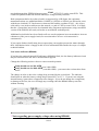
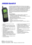
Neue Seite 1
AR8600 Bulletin Page
The bulletins contained on this page are not generally intended for self-fit, they generally
represent 'dealer assistance'. Fitting of the optional filters, optional battery and enabling of I.F.
output is intended for action by workshop technicians. No liability is accepted for damage
caused by inexperienced personnel.
AR8600 MK1 to MK2
The AR8600 Mark2 has been introduced during June 2002. The main RF PCB is completely
revised, it is not possible to update a Mark1 to a Mark2 by simple component change... the
frequency coverage has also been extended with a revised CPU being employed.
AR8600 I.F. output
The AR8600 is provided with a rear BNC socket which provides 10.7MHz I.F. output. The
bandwidth is about 2MHz and our workshop measurements using WFM mode suggest that a
positive gain exists between aerial input and I.F. output of 35dB to 40dB across the frequency
bands.
Out of the carton box, I.F. output is limited to WFM mode only to minimise the effects of
internal spurii, as the WFM oscillator is used to produce the 10.7MHz I.F. output. If you wish to
obtain I.F. output in ALL MODES, please refer to the associated bulletin (Acrobat PDF file) click here.
While the AR8600 may be used with either the SDU5000 or SDU5500 is passive mode, the
RS232 communication with either spectrum display unit is not supported.
Failure of IC410 - over-voltage (early AR8600 MK1)
We have encountered two AR8600 which have suffered damage due to over-voltage power
being applied to the power socket (20V), one via an unregulated power supply and the other by
vehicle connection. Here in the UK we only supply 12V & 15V ‘REGULATED’ power
supplies for the AR8600 (UK manufactured)... we cannot comment on power supplies provided
outside of the UK.
In both cases, the voltage regulator on the CPU PCB IC410 (TK11245) had failed, which in
Seite 1
Neue Seite 1
turn had damaged the EEPROM memory store IC402 (AT29C512) on the same PCB. This
resulted in spurious behaviour and the inability to change memory contents.
Both components had to be replaced, and it is suggested (by AOR Japan, the equipment
manufacturer) that two additional diodes (1N4148 or 1SS1588 or 1SS266) are inserted in series
with the un-switched 12V line between connector J403 and the regulator IC410… this is best
achieved by a cut in the track between the unused +ve pad of C426 en-route IC410. It is likely
that the ‘system data’ may need to be reinstated after component replacement, using a modified
version of the EM8200 slot card (referred to as an AR8600 workshop tool).
Additional series diodes have been fitted to all new stock equipment in recent months to increase
robustness of the power supply circuit (for occasions where an over-volt connection is
encountered).
If you require further clarification, please request that your supplier pursues the matter through
their ‘distribution chain’ of supply as this level of information falls outside the scope of a simple
technical bulletin.
Low batter indicator (BP8600)
If you have the optional internal NiCad battery (BP8600) fitted, the low battery indicator circuit
may not function when the above modification is applied.
Change the following resistor values to restore normal operation:
R446 should now be 56k OHM (was 100k OHM)
R447 should now be 100k OHM (was 68k OHM)... you can use the resistor taken from
R447
The change in value is due to the voltage drop presented by the series diode. The indicator
should turn on when the battery voltage drops around 8.2V to 8.3 V. If you are not using the
internal battery, ignore these component value changes. If you do not change the components,
no damage will occur, the set will simply stop working when the BP8600 battery runs flat without warning.
* Note regarding power supply voltage when using BP8600
Seite 2
Neue Seite 1
Initially designed to provide up to two hours of operation, tests have shown that once the
internal battery has been fully charged using an optional 15V regulated DC power supply, the
monitoring time extends to around FIVE HOURS (with back-lit LCD lamps off).
Note: Operational times are for guidance but depend upon the style of operation (volume level,
backlight, scanning etc) and are not guaranteed.
Corrupt data AR8600 (also applies to AR8200 MK1 and MK2)
If your AR8200 is behaving strangely such as locking up or powering down unexpectedly, it may
be suffering from corrupt data (programmable data or system data or both) due to a power glitch
(a.c. supply interruption, battery low etc).
The corruption can affect the search bank, memory bank (or channel) or indexes such as pass list
of select scan list. Instead of the data reading (for example) 123.450 MHz, it will attempt to
read 123.zv0 MHz... as the corrupt data
is not recognised, it caused the AR8200 to 'crash' - like a computer program.
Try deleting & over-writing search banks, pass lists, select scan lists etc.
If the problem persists, it may require the system data to be refreshed using a modified version of
the EM8200 external memory card (which allows system data to be written). If you already have
an EM8200 card, your supplier may be able to arrange for the EM8200 to be modified and
loaded with default data (so the recovery procedure will be just a couple of key presses). Please
contact your supplier if you are unable to progress the matter.
EM8200 external memory slot card with AR8600
Following a report by Bob Farish (direct and via the internet) we investigated a report that
memory data was being lost when using the AR8600 with the EM8200 external memory slot
card.
The problem shows if the single 'memory bank' function is used.
No problems are experienced if 'all memories' are used.
If a single memory bank is loaded to the slot card , it is stored correctly.
If the single memory bank is loaded back to the set, the memories and individual text comments
Seite 3
Neue Seite 1
are re-loaded to the set correctly but the overall 'bank' text comment is not re-loaded (this
appears to be the case regardless of if the set is in scan, search or VFO).
However if the set is being used on a different memory bank to that being re-loaded from the slot
card, the overall bank text comment is then correct for the re-loaded bank, BUT, the bank that
the set was being used on then gets labelled with whatever text comment was previously in the
bank being overwritten.
This only happens in the AR8600 (mk1 & 2). It isn't a problem in the AR8200mk3.
RU8200 operating manual inconsistencies
Inconsistencies have been reported to us regarding the operation of the RU8200 record /
playback option with the AR8600 (particularly in continuous loop mode), neither the AR8600
operating manual or RU8200 product leaflet are 100% accurate. The revised section of the
operating manual is presented here, the main areas of charge are highlighted in red colour:
18-2 Slot card OPTION menu - registering a slot card
Once the slot cards have been fitted, they must be registered for use via the slot card menu.
This is because only one slot card from GROUP 1 and one slot card from GROUP 2 can be used
simultaneously, registering the slot cards is a way of managing their use.
The optional slot cards must be REGISTERED via the SLOT CARD OPTION MENU
before they can be manipulated via their own control menus. To access the slot card registration
menu option menu PUSH [FUNC] PRESS [CLEAR]
The menu is presented in two sections (pages), the first covers the slot cards in GROUP 1
(TE8200, CT8200, VI8200) and the second page covers the slot cards in GROUP 2 (EM8200,
RU8200).
The UP / DOWN arrow keys are used to move between lines representing the slot card fitted, if
you do not have the listed card fitted, you will not be able to move to the displayed line, it will be
skipped.
For example, if you have the TE8200 and VI8200 slot cards fitted, pressing the DOWN key will
skip over the CT8200 selection line, the second page containing the EM8200 and RU8200
entries will also be inaccessible. The UP key may be used to move backward through the menu
items. Ignore the “AUT” legend if displayed on the LCD.
When the cursor is flashing on the desired line for the required option, use LEFT / RIGHT arrow
or [PASS] key or MAIN DIAL to REGISTER or DE-REGISTER the option as a toggle. When
registered, the legend ‘STAR’ will be displayed on the LCD next to the slot card description.
Seite 4
Neue Seite 1
Remember, you may register one slot card from GROUP 1 and one card from GROUP 2 for
simultaneous operation if desired. To complete the selection, PUSH [ENT]
18-6 RU8200 optional record & playback slot card
The RU8200 enables around 20 seconds of audio to be recorded to a chip within the RU8200 for
playback at a later time. The chip may be used to recorded over and over again overwriting the
previous recordings. The recording may also be played back over and over, very useful if you
have grabbed an interesting recording! It is also possible to set the RU8200 to continuously
record the last 20 seconds of activity ensuring that an interesting transmission is never missed.
The RU8200 may be used in VFO, scan, search but note the following:
VFO mode: The RU8200 operates as laid out here, recording starts when the squelch opens or
records immediately if the squelch is already open. When recording has started, manual
operation of the front panel squelch control is disabled. The RU8200 is best suited to use in
VFO mode.
SCAN / SEARCH mode: The RU8200 will start recording when the squelch opens but
recording will stop immediately once the squelch closes and the receiver continues scanning or
searching. As the recording has been deactivated when the receiver moves to new channels,
accidental overwriting of the recording is prevented. If however you want to record every active
channel that the receivers finds, select CONTINUOUS from the record menu. In
CONTINUOUS mode, when the receiver stops on a busy channel, the recording will start
automatically, however when the receiver moves to another channel (automatically during scan
& search), the previous recording will be stopped and a new session started - speedy manual
intervention is required.
Register the RU8200 slot card
Insert the RU8200 slot card and switch the AR8600 on and REGISTER the RU8200 card via
the OPTION SELECT registration menu. Refer to section 18-2 and the example for the
TE8200 shown in section 18-3. Remember, the RU8200 is listed in group 2 of the slot card
option list.
To use the RU8200
Insert the RU8200 slot card and switch the AR8600 on, select VFO mode. PUSH [FUNC]
PUSH [CLEAR] to access the RU8200 menu. The AR8600 will present the record / playback
menu. The legend “RECORDER ” confirms selection of the record & playback menu. PUSH
the [PASS] key or use the main dial or LEFT / RIGHT arrow keys to toggle between “REC”
(RECORD ), “C.REC” (continuous record) and “PLAY ” (play).
PUSH [ENT] to accept the selection and return to the previous menu or PUSH [CLEAR] to
abort. Recording and playback can be carried out while the AR8600 is in VFO, scan or search
mode.
Seite 5
Neue Seite 1
18-6-1 Recording
While in the record & playback menu select “REC ” and PUSH [ENT]. The LCD will return to
its previous display with the legend “REC” in the bottom left corner of the LCD to show that
the RU8200 is active. If the squelch is currently open, recording will take place immediately,
otherwise recording will take place next time the squelch opens.
While recording is in progress, the second line from the bottom of the LCD (usually displaying
the standby frequency in 2VFO mode) changes to a progress bar “REC =====>” indicating that
recording is in progress. Once started, the recording process continues for about 20 seconds and
the legend “End” is displayed when the recording process is complete. Once started, recording
continues even if the squelch closes but you may PUSH the [CLEAR] key half way through a
recording to stop it from recording 20 seconds of nothing! PUSH the [CLEAR] key after
recording has ended to clear the recording related text from the LCD.
Continuous recording
To enable continuous recording of the last 20 seconds, select “REC ” while in the record &
playback menu select then PUSH [ENT]. The LCD will return to its previous display with the
legend “REC” in the bottom left corner of the LCD to show that the RU8200 is active. If the
squelch is currently open, recording will take place immediately, otherwise recording will take
place next time the squelch opens. When the 20 second recording process has completed,
recording will simple start again from the beginning forming a loop.
a) To force a new 20 second record period to commence, PUSH [ENT]
b) To stop the current recording to stop at the end of the current 20 second block,
PUSH [CLEAR]
c) To stop recording immediately, PUSH [CLEAR] PUSH [CLEAR]
Note: RU8200 recording is disabled when the band scope facility is operational.
18-6-2 Playback
It is assumed that you have already made a recording. While in the record & playback menu
select “PLAY ” and PUSH [ENT]. The LCD will return to its previous display with the legend
“PLY” in the bottom left corner of the LCD to show that the RU8200 is active. Playback will
start instantly.
While playback is in progress, the second line from the bottom of the LCD (usually displaying
the standby frequency in 2VFO mode) changes to a progress bar “PLY =====>” indicating that
playback is in progress. Once started, the playback process continues for about 20 seconds and
the legend “End” is displayed when the playback is complete.
You may PUSH the [CLEAR] key to cancel playback or clear the recording related text from the
LCD.
Seite 6
Neue Seite 1
Note: No liability in any form will be accepted in respect of recordings made using the RU8200
option.
Lack of SSB reception - resonator replacement
We have received two reports of lack of SSB reception with the AR8600 series, either USB or
LSB failure. On both occasions, the problem has been traced to failure of the SSB resonator
with simple replacement clearing the fault.
AR8600 (MK2) USB and LSB resonator replacement.
Remove top and bottom case halves (16 screws).
Remove top chassis cover (6 screws – 3 down each side), unclip speaker wire).
Remove bottom chassis cover (3 black, threaded screws in centre of board from top and 6 screws
from bottom).
Looking from the front, top of the AR8600, the SSB resonators are located in the front, right
hand corner of the set.
The board is marked;
X3 LSB - This should be 453.5kHz (marked 453)
X4 USB/CW - This should be 456.5kHz (marked 456).
Replacement is simply by de-soldering the device and fitting a new one.
If one has stopped oscillating, before replacing it, check that none of the surrounding devices
have any dry or failed joints.
In practice, alignment of these devices will not have been set up too critically and will probably
not require much alignment.
They can be aligned if necessary.
According to the service manual;
For LSB, with the receiver set to 5.000MHz, adjust VC1 and VC2 for a BFO output of
453.5kHz +/- 50Hz (measured at TP105-1, labelled BFO on board).
For USB, adjust VC3 and VC4 for 456.5kHz +/- 50Hz.
Seite 7
Neue Seite 1
In practice, if the set is up to working temperature and is known to be aligned very closely to
correct frequency at a spot frequency, then the trimmers can be aligned by ear for correct
sounding audio on SSB using either a known SSB transmission of the side band or a known AM
signal. This will only work if the set is close to actual frequency. If it is not, it will either be
impossible to adjust the trimmers far enough or the resultant audio tone when switching between
side bands will be markedly different (even just on background noise).
All of this is of course far easier if a frequency counter (and signal generator) are available.
Re-fitting case parts is the reverse of the above.
AR8600 MK1
The procedure is the same as above for the mark 1 sets with the following differences;
The LSB resonator is now labelled as X104 and the USB one as X103.
The LSB resonator frequency is aligned by VC104 and USB by VC105.
The output frequency can be measured at TP105.
Viewed from the front of the set, the resonator location is on the right hand side of the set about
half way back.
Seite 8