1
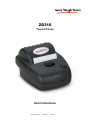
ZG310
Thermal Printer
User Instructions
AWT 35-500729
Issue AA
July 2011
© Avery Weigh-Tronix, LLC 2011. All rights reserved.
No part of this publication may be reproduced, stored in an electronic retrieval system, or transmitted in any form
or by any means, electronic, mechanical, photocopying, recording or otherwise without the prior written consent of
the copyright owner, or as permitted by law or under license. Full acknowledgment of the source must be given.
Avery Weigh-Tronix is a registered trade mark of the Avery Weigh-Tronix, LLC. This publication was correct at the
time of going to print however, Avery Weigh-Tronix, LLC reserves the right to alter without notice the specification,
design, price or conditions of supply of any product or service at any time.
All third party brands and product names used within this document are trademarks or registered trademarks of
their respective holders.
ZG310_u_en_500729.book
Table of Contents
Chapter 1 General Information and Warnings ........................................................................................ 5
About this Manual .............................................................................................................. 5
Special Messages .............................................................................................................. 5
Electrical Installation .......................................................................................................... 6
Pluggable Equipment ......................................................................................................... 6
Wet Conditions ................................................................................................................... 6
Routine Maintenance ......................................................................................................... 6
Installation .......................................................................................................................... 6
Power Supply Details ......................................................................................................... 6
Alternative Power Supply Arrangements ..................................................................... 7
Printer Firmware Revisions ................................................................................................ 7
Copyright Notice and Disclaimer ........................................................................................ 7
EMC Caution ...................................................................................................................... 8
Chapter 2 Getting Started ......................................................................................................................... 9
Connections and EMC Precautions ................................................................................... 9
Connector Details ........................................................................................................ 9
Connector Pinouts ....................................................................................................... 9
Connecting to a PC .......................................................................................................... 10
Application Program .................................................................................................. 11
Chapter 3 Modes of Operation ............................................................................................................... 12
Idle Mode ......................................................................................................................... 12
Spool Mode ...................................................................................................................... 12
LED Indications ................................................................................................................ 12
Chapter 4 Paper ....................................................................................................................................... 14
Loading Paper .................................................................................................................. 14
Paper Out and Head Up Sensors .................................................................................... 14
Chapter 5 Printer Operation and Programming .................................................................................... 15
Data Buffer ....................................................................................................................... 15
Spool Mode ...................................................................................................................... 15
Character Printing and Fonts ........................................................................................... 15
Graphics Printing and Other Programming Modes .......................................................... 16
Interface Details ............................................................................................................... 16
RS-232 Serial Interface ............................................................................................. 16
ZG310 Thermal Printer User Instructions
3
4
ZG310 Thermal Printer User Instructions
1
General Information and Warnings
1.1
About this Manual
This manual consists of user instructions to be used as a guide for printer installation
and operation. Be sure to read all instructions before making any connections.
The manual is divided into chapters by the chapter number and the large text at the top
of a page. Subsections are labeled as shown by the 1 and 1.1 headings shown above.
The manual name and page numbers appear at the bottom of the pages.
1.2
Special Messages
Examples of special messages you will see in this manual are defined below. The
signal words have specific meanings to alert you to additional information or the relative
level of hazard.
ELECTRICAL WARNING!
THIS IS AN ELECTRICAL WARNING SYMBOL.
ELECTRICAL WARNINGS MEAN THAT FAILURE TO FOLLOW SPECIFIC PRACTICES OR PROCEDURES MAY RESULT IN ELECTROCUTION, ARC BURNS, EXPLOSIONS OR OTHER HAZARDS THAT MAY
CAUSE INJURY OR DEATH.
CAUTION!
This is a Caution symbol.
Cautions give information about procedures that, if not observed, could result
in damage to equipment or corruption to and loss of data.
NOTE: This is a Note symbol. Notes give additional and important information, hints
and tips that help you to use your product.
ZG310 Thermal Printer User Instructions
5
1.3
Electrical Installation
CAUTION: The power cable must be connected to an earth-grounded electrical
outlet. The electrical supply must have a circuit breaker with an appropriate
rating to protect from over-current conditions.
IF IN DOUBT SEEK ADVICE FROM A QUALIFIED ELECTRICIAN.
1.4
Pluggable Equipment
Pluggable equipment must be installed near an easily accessible socket outlet.
1.5
Wet Conditions
The Model ZG310 printer is not a washdown unit. Do not install near water!
1.6
Routine Maintenance
Always turn off the ZG310 and isolate from the power supply before starting any routine
maintenance to avoid the possibility of electric shock.
Make sure that it is placed securely on a flat and level surface.
1.7
Installation
DANGER: RISK OF ELECTRICAL SHOCK. NO USER SERVICEABLE
PARTS. REFER TO QUALIFIED SERVICE PERSONNEL FOR SERVICE.
1.8
Power Supply Details
The ZG310 is directly powered through the power jack at the rear of the printer.
The printer is designed for direct connection to a +12V or +24V vehicle battery.
Alternatively, the user may make their own power supply arrangements as described
below.
6
ZG310 Thermal Printer User Instructions
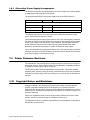
1.8.1 Alternative Power Supply Arrangements
The ZG310 is designed to be operated from a 9V to 36V voltage source that is capable
of supplying the primary power for the printer.
The electrical specification for the power supply input of the ZG310 printer is:
Input Voltage Range:
+9V to +36V
Supply Current Requirement:
( typical @24V in )
50mA
internal over voltage at 37V and reversal protection
Printer in Idle Mode
1A average
Printer Printing
4A peak
Printer Printing
The average and peak current requirements can be adjusted by firmware control
codes. See the Service Manual for details.
The recommended power supply input is either a 12V or 24V vehicle battery, this allows
the printer to perform at its best. However, the printer will automatically accommodate
any DC input voltage in the range 9V to 36V. In addition, power supplies with lower
current capacities may be accommodated by varying the internal Power Save
parameter. See the Service Manual or contact the factory for more details.
The recommended power supply input is either a 12V or 24V vehicle battery, this allows
the printer to perform at its best. However, the printer will automatically accommodate
any DC input voltage in the range 9V to 36V.
1.9
Printer Firmware Revisions
The manufacturer reserves the right to modify and improve the firmware in its printer
products at any time. Every effort is made to ensure backward compatibility, however,
no guarantee in this respect is given or implied.
The ZG310 includes a flash-reprogrammable microcontroller. This allows firmware
upgrades under customer control (including customized fonts, which may be created
using the Font Editor Utility). Refer to the factory for more information in this feature, if
required.
1.10 Copyright Notice and Disclaimer
Copyright subsists in the manufacturer's intellectual property, including controller
firmware (embedded software) and circuit diagrams, pin connection lists and
application data. No warranty in respect of patent rights of the manufacturer or of third
parties is given. Unauthorized reproduction or amendment of controller firmware may
result in prosecution.
Fujitsu is a registered mark of its owner Fujitsu Limited. References to this or other
owners' marks in this document are for illustrative purposes only.
The manufacturer does not assume responsibility for interchangeable functionality of
other parties' command sets.
ZG310 Thermal Printer User Instructions
7
1.11 EMC Caution
System EMC compliance remains the responsibility of the system designer. It is
recommended that screened cables are used; earthing arrangements will depend on
the application.
8
ZG310 Thermal Printer User Instructions
2
Getting Started
2.1
Connections and EMC Precautions
2.1.1 Connector Details
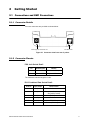
Two user connectors are provided as shown below:
Power Supply Input Jack Socket Jack
RJ12 Data Socket
Figure 2.1 Connector view from rear of printer.
2.1.2 Connector Pinouts
PSU Jack Socket Detail
Pin
Dimension (mm)
Function
Inner
Inside Ø 2.1
Positive 9-36 VDC Input
Outer
Outside Ø 5.5
Negative / 0V Common
The maximum insertion length is 12 mm.
RJ12 Combined Data Socket Detail:
RJ12 Pin
Input / Output
ZG310 Function
1
i/p
No Connection
2
i/p
Wake-up Input (Only when optional
sleep mode is enabled)
3
i/p
RS-232 Rx data
4
o/p
RS-232 Tx data
5
o/p
RS-232 Busy
6
---
0V Common (RS-232 signal return)
ZG310 Thermal Printer User Instructions
9
RS232 Data Cable Configuration (9 pin):
2.2
D-9 Pin
Name
Function (refers to PC)
ZG310 Pin
3
TxD
Serial Data Output
3
2
RxD
Serial Data Input
4
6&8
CTS & DSR
Busy Input
5
5
SGND
Signal Common 0V
6
Connecting to a PC
1.
Make hardware connections.
1a.
Be sure the PC has a D-type serial connector; otherwise, a serial to USB
converter will need to be used.
2.
Use any of the available serial ports of the ZG310.
3.
Make sure that the power supply is switched on and connected. The LED
indicator should light; if it does not, check the power supply and connections.
4.
Load paper and then press the feed button to check that paper feeds. Press
the paper feed button again twice in quick succession (like double-clicking a
PC mouse) and the printer should print a self-test message. This will show that
the printer is operational, and also reports the way in which the printer's serial
data interface is configured.
5.
Set up the computer's serial port to match the printer
5a.
Your proposed application program may have a way of doing this, or you can
get to the DOS prompt [eg C:\>] and type the following command line
(assuming you have connected the printer to COM1:):
MODE COM1:9600,N,8,1 [ENTER]
5b.
This will set up the port (COM1:) to 9600 baud, No parity, 8 data bits, and 1
stop bits which is the default setting for the ZG310.
6.
Send some data to the printer from your computer. An easy way to do this from
the DOS prompt is to type:
DIR >COM1: [ENTER]
6a.
This should send a directory listing to the printer. The lines will probably
overflow, but it will at least show that the communication between the
computer and the printer is working.
6b.
You can also send data from QBASIC, for example:
OPEN "COM1:9600,N,8,1" FOR RANDOM AS #1
PRINT#1, "Hello"
6c.
10
Alternatively, in Windows, use the terminal (Hyper terminal) program to send
some text to the printer.
ZG310 Thermal Printer User Instructions
2.2.1 Application Program
Once communications between your computer and the printer have been established,
you can try driving the printer from your application program.
As referred to in the Programmers Guide, the ZG310 has a control code set based on
the EPSON ESCPOS protocol. Many of the commands are as closely compatible as
they can be, given the mechanical differences between printers, but if the application
program was originally written for another printer, it may need to be modified.
ZG310 Thermal Printer User Instructions
11
3
Modes of Operation
The ZG310 has two operating modes, when not actually printing:
l
Idle Mode: ready to accept data, but no data is in the buffer awaiting
printing, and the printer motor is not running;
l
Spool Mode: active, but storing data for later printing.
Modes are indicated by different color combinations on the front-panel LED (see page
12).
The ZG310 is supplied configured as permanently powered on whenever the power
supply is connected and switched on.
The ZG310 may optionally be supplied with a sleep mode feature. The sleep period is
configurable between 1 and 65534 seconds.
3.1
Idle Mode
In idle mode, the printer is ready to receive data, which will be printed as soon as
complete lines or graphics patterns are decoded. It responds to the paper feed button
normally and can also produce a demonstration print (see below).
3.2
Spool Mode
In spool mode, data is received and stored, but not printed. This is useful when printing
needs to be suppressed during data transfer (for example in mobile radio systems); or
when the printer is unable to print because the paper has run out or the lid is open.
The ZG310 will automatically enter spool mode when the paper is out, when the head
is up, or if some other error condition occurs, or alternatively by command from the
host. Spool mode may be cleared by host command, automatically when the condition
is cleared, or by "double-clicking" the feed button.
3.3
LED Indications
The LED indicator at the front of the ZG310 has a number of color combinations, which
repeat in up to a 4-phase pattern to provide status information (see table below).
In summary:
l
l
l
l
12
If the LED is constant green it indicates that the printer is operating normally.
Flashing on and off indicates that Spool mode is active and no printing can
take place.
Red warns of a low power supply voltage or other problem.
No light indicates that the unit is off.
ZG310 Thermal Printer User Instructions
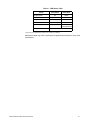
Table 3.1 LED Pattern Table
Pattern
Power Status
Buffer Mode
Constant Green
OK
Normal
Fast Flashing Green
OK
Spool *
Long Green - Short Red
Low Voltage
Normal
Short Green - Short Red
Low Voltage
Spool *
Error Condition
Spool
(Printing prohibited)
Fast Flashing Red
No light
Printer is off
* (Spool may have resulted from Paper Out or Head Up conditions)
Although this table may seem complicated, few applications will produce many of the
combinations.
ZG310 Thermal Printer User Instructions
13
4
Paper
Pressing the paper feed button when the printer is idle, or in spool mode, advances
paper at typically 50 mm per second. However, the feed button has additional
functions:
Double-clicking the button (i.e. pressing and releasing twice in quick succession just
like a PC mouse):
l
l
in idle mode, prints a demo/test message including the firmware version,
encoded calibration data, and the full character set;
in spool mode, or having been out of paper, prints any stored data and enters
idle mode.
Some of the functions of the paper feed button can be invoked or disabled under control
of the host.
4.1
Loading Paper
Paper rolls must be 57.5 ± 0.5 mm wide, 55 mm maximum diameter, and have the
thermally sensitive coating on the outside. The printer can accept rolls which are
coreless or wound on a core.
To load a new roll of paper:
1.
Slide the lid release button forwards until the lid springs open.
2.
Unwind a small amount of paper from the roll and insert the paper roll into the
printer.
3.
Close lid and the paper is loaded.
After loading, check that the paper is straight and advances properly, and tear off any
excess by pulling the paper sharply towards you across the serrated tear bar. In the
event of a jam or other paper loading problem, release the lid and straighten the paper
before closing again.
4.2
Paper Out and Head Up Sensors
A reflective optical Paper Out sensor within the mechanism detects an out-of-paper
condition, and/or senses black marks to register with pre-printed forms. A mechanical
Head Up sensor detects when the lid is open.
By default, the printer enters spool mode automatically if either sensor becomes active.
spool mode is automatically exited, and any stored data printed, when new paper is
loaded and the lid closed. This behavior may be modified. Please refer to the Service
Manual for details of how to configure these functions.
14
ZG310 Thermal Printer User Instructions
5
Printer Operation and Programming
The ZG310 utilizes a Fujitsu FTP-628MCL103 printer mechanism, with a fixed
(parallel) print head with 384 horizontally-arranged thermal elements. The paper is
advanced by a stepper motor, and printing takes place in a single dot row for each step
of the paper. Each printed dot is approximately 1/8 mm square. The printing speed and
dot density are controlled according to the power supply voltage and the head
temperature.
Various printing modes, including graphics, are invoked by Escape sequences. Control
codes and status report protocols are described in detail in the Service Manual which
is provided separately.
5.1
Data Buffer
The ZG310 has a nominal 20k byte buffer to optimize throughput which enables data
to be received into the buffer while previous lines are being printed. Printing will be
initiated on receipt of a valid logical line of data or a complete graphics pattern.
The buffer may be cleared by data command or by a hardware reset. A partially full line
will be printed on receipt of an appropriate control code, or after a programmable
timeout delay.
5.2
Spool Mode
Spool mode can be entered by one of the following:
l
a command from the host
l
a paper out condition or head up condition being sensed.
l
an error condition (e.g. head over temperature, over voltage, etc).
In spool mode, the buffered data are stored without being printed until the mode is
exited by:
5.3
l
a command from the host.
l
a causing condition (e.g. Paper Out or Head Up) being cleared.
l
the paper feed button being double-clicked.
Character Printing and Fonts
The default 32-column character set is formed from a 24x10 dot matrix, and is based
on the industry standard IBM® character set Code. This character set has been
modified to include the Euro symbol ('€') at position 80H (128 Decimal), in place of the
usual capital C with cedilla ('Ç').
Various combinations of single or double width, single or double height, inverted,
underlined, and other attributes may be mixed within a line.
Customized fonts may be created using the Font Editor Utility, and downloaded to the
ZG310. Only a single custom font may be loaded in the printer at one time, and having
a custom font installed prevents the internal fonts from being accessed. Depending on
the attributes of the custom font, graphics operations may be affected.
ZG310 Thermal Printer User Instructions
15
5.4
Graphics Printing and Other Programming Modes
Various dot-addressable graphics modes are supported, at up to 384 dots per line.
Refer to the Service Manual for full details of this and other advanced programming
modes.
5.5
Interface Details
5.5.1 RS-232 Serial Interface
The ZG310 printer has an industry standard RS-232 interface. The default parameters
are 9600 baud, 8 data bits, 1 stop bit and no parity. Other baud rates can be
programmed by control codes, or by using a setup utility available from the factory.
Serial data is expected in standard RS-232 format with -12V meaning mark or 1 and
+12V a logical 0, with reference to the common ground. The serial data output line,
TxD, transmits XON/XOFF and status information to the host at the same baud rate
and in the same format as the serial data input.
The hardware busy line is true (nominal -12V) when busy. Both serial output lines will
relax to approximately 0V when the ZG310 is off, and the user must allow a short period
after switching on before relying on the values of these signals.
Some host equipment uses a constant space condition (+12V) to indicate a reset
condition or wait state. Some battery powered host equipment present the same output
signal when they go to sleep. The ZG310 can be set to ignore this condition as detailed
in the Service Manual, but even then this type of host behavior may result in one or
more spurious characters being received and printed.
16
ZG310 Thermal Printer User Instructions
Avery Weigh-Tronix USA
1000 Armstrong Dr.
Fairmont MN 56031 USA
Tel:507-238-4461
Fax:507-238-4195
Email: [email protected]
www.wtxweb.com
Avery Weigh-Tronix UK
Foundry Lane,
Smethwick, West Midlands,
England B66 2LP
Tel:+44 (0) 8453 66 77 88
Fax: +44 (0)121 224 8183
Email: [email protected]
www.averyweigh-tronix.com