1
s
Preface, Contents
What's new in
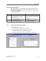
S7-Technology V2.0
1
Application and usage
2
Technology objects
3
S7-300
CPU 317T:
Technology Functions
Configuration
4
Programming
5
Manual
Technology functions
6
Technology DBs
7
Download, testing and
diagnostics
8
Appendix
A
SIMATIC
Index
Edition 11/2004
A5E00251798-03
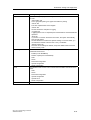
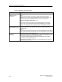
Safety Guidelines
This manual contains notices intended to ensure personal safety, as well as to protect the products and
connected equipment against damage. These notices are highlighted by the symbols shown below and
graded according to severity by the following texts:
!
Danger
!
Warning
!
Caution
indicates that death, severe personal injury or substantial property damage will result if proper
precautions are not taken.
indicates that death, severe personal injury or substantial property damage can result if proper
precautions are not taken.
indicates that minor personal injury can result if proper precautions are not taken.
Caution
indicates that property damage can result if proper precautions are not taken.
Notice
draws your attention to particularly important information on the product, handling the product, or to a
particular part of the documentation.
Qualified Personnel
Only qualified personnel should be allowed to install and work on this equipment. Qualified persons
are defined as persons who are authorized to commission, to ground and to tag circuits, equipment, and
systems in accordance with established safety practices and standards.
Correct Usage
Note the following:
!
Warning
This device and its components may only be used for the applications described in the catalog or the
technical description, and only in connection with devices or components from other manufacturers
which have been approved or recommended by Siemens.
This product can only function correctly and safely if it is transported, stored, set up, and installed
correctly, and operated and maintained as recommended.
Trademarks
SIMATIC®, SIMATIC HMI® and SIMATIC NET® are registered trademarks of SIEMENS AG.
Third parties using for their own purposes any other names in this document which refer to trademarks
might infringe upon the rights of the trademark owners.
Copyright Siemens AG 2004 All rights reserved
Disclaimer of Liability
The reproduction, transmission or use of this document or its
contents is not permitted without express written authority.
Offenders will be liable for damages. All rights, including rights
created by patent grant or registration of a utility model or design,
are reserved.
We have checked the contents of this manual for agreement with
the hardware and software described. Since deviations cannot be
precluded entirely, we cannot guarantee full agreement. However,
the data in this manual are reviewed regularly and any necessary
corrections included in subsequent editions. Suggestions for
improvement are welcomed.
Siemens AG
Bereich Automation and Drives
Geschaeftsgebiet Industrial Automation Systems
Postfach 4848, D- 90327 Nuernberg
Siemens AG 2004
Technical data subject to change.
Siemens Aktiengesellschaft
A5E00251798-03
Preface
Purpose of this manuals
This manual gives you a complete overview of the optional software package
"S7-Technology". The programming model, the individual technological objects and
the individual function blocks according to PLCopen are explained.
It is designed for STEP 7 programmers and persons who work in the configuration,
commissioning and automation system service with Motion Control application
sector.
Required basic knowledge
To understand this manual you require a general knowledge in the automation
technology and motion control field.
Users should be familiar in operating computers and programming devices on a
Windows 2000 Professional or XP operating system platform. Adequate knowledge
of the STEP 7 standard software is essential, because the optional software
package "S7-Technology" is based on this software. The appropriate knowledge
base is found in the “Programming with STEP 7“ manual.
Range of validity of this manual
This manual applies to the optional software package "S7-Technology" V 2.0 or
higher. In the chapter "What's New in S7 Technology V 2.0?" you will find the
differences in functionality and specifications of this version in comparison to the
"S7 Technology" optional software package version V1.0.
CPU 317T: Technology Functions
A5E00251798-03
iii
Preface
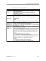
Position in the world of documentation
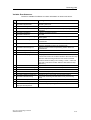
This manual forms part of the 317T-2 DP CPU documentation package.
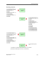
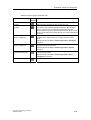
Manual
Getting Started
CPU 317T-2 DP: Commissioning
CPU Data Reference Manual
CPU Data: CPU 317T-2 DP
Manual
CPU 317T: Technology functions
In this manual you find:
Purpose
Based on a practical example, this Getting
Started guides you through the steps in
commissioning a fully functional
application.
Describes the operation, functions and
technical data of a 317T-2 DP CPU.
There you will also find changes and
enhancements not included in the
installation manual for your
317T-2 DP CPU.
Describes the various technological
functions:
• Applications and usage
• Basics and configuration
• Download, testing and diagnostics
• PLCopen functions
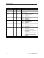
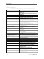
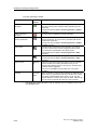
Product Information
Connecting SIMOVERT MASTERDRIVES MC
to the Technology CPU
Product Information
Connecting SIMODRIVE 611U to the
Technology CPU
Equipment Manual
ADI – Analog Drive Interface for 4 Axes
Installation Manual
S7-300 PLCs:
Installation: 31xC CPU and 31x CPU
Module Data Reference Manual
S7-300 PLCs: Module data
Operations list CPU 31xC, CPU 31x
IM 151-7CPU, BM 147-1CPU, BM 147-2CPU
iv
Describes how to connect and commission
the SIMOVERT Master drive MC to the
CPU317T-2 DP.
Describes how to connect and commission
SIMODRIVE 611 U to the CPU317T-2 DP.
Describes how to connect and commission
the ADI 4 to the CPU 317T-2 DP as well as
other SIMOTION operating units.
Describes the engineering, installation,
networking and commissioning of an
S7-300.
Describes the functions and the technical
data of signal modules, power supply
modules and interface modules.
Lists the instruction set of the CPUs and
the corresponding execution times. List of
executable blocks (OBs/SFCs/SFBs) and
their execution times.
CPU 317T: Technology Functions
A5E00251798-03
Preface
Further Support
If you have any technical questions, please get in touch with your Siemens
representative or agent responsible.
You will find your contact person at:
http://www.siemens.com/automation/partner
You will find a guide to the technical documentation offered for the individual
SIMATIC Products and Systems here at:
http://www.siemens.com/simatic-tech-doku-portal
The online catalog and order system is found at:
http://mall.ad.siemens.com/
Training Centers
Siemens offers a number of training courses to familiarize you with the SIMATIC
S7 automation system. Please contact your regional training center or our central
training center in D 90327 Nuremberg, Germany for details:
Telephone: +49 (911) 895-3200.
Internet:
http://www.sitrain.com
CPU 317T: Technology Functions
A5E00251798-03
v
Preface
Technical Support
You can reach the Technical Support for all A&D products
•
Via the Web formula for the Support Request
http://www.siemens.com/automation/support-request
•
Phone:
+ 49 180 5050 222
•
Fax:
+ 49 180 5050 223
Additional information about our Technical Support can be found on the Internet
pages http://www.siemens.com/automation/service
Service & Support on the Internet
In addition to our documentation, we offer our Know-how online on the internet at:
http://www.siemens.com/automation/service&support
where you will find the following:
vi
•
The newsletter, which constantly provides you with up-to-date information on
your products.
•
The right documents via our Search function in Service & Support.
•
A forum, where users and experts from all over the world exchange their
experiences.
•
Your local representative for Automation & Drives.
•
Information on field service, repairs, spare parts and more under "Services".
CPU 317T: Technology Functions
A5E00251798-03
Contents
1
What's new in S7-Technology V2.0
1-1
2
Application and usage
2-1
2.1
2.2
2.3
2.4
2.5
2.6
2.6.1
2.6.2
2.6.3
3
Compact and integrated....................................................................................2-1
The familiar "SIMATIC world"............................................................................2-1
Integrated PLCopen-compliant motion control functions in STEP 7.................2-2
Available components and systems..................................................................2-2
Project data volume and operating conditions ..................................................2-5
Components and their tasks .............................................................................2-6
Hardware components ......................................................................................2-6
Engineering tools ..............................................................................................2-7
Technology functions and technology DBs.....................................................2-10
Technology objects
3.1
3.1.1
3.1.2
3.1.3
3.1.4
3.1.5
3.1.6
3.1.7
3.1.8
3.2
3.3
3.3.1
3.4
3.4.1
3.4.2
3.4.3
3.4.4
3.4.5
3.5
3.5.1
3.5.2
3.5.3
3.5.4
3.6
3.6.1
3.6.2
3.6.3
3.6.4
3.6.5
3.6.6
3.6.7
3-1
Axes - Basics ....................................................................................................3-1
Axis technologies ..............................................................................................3-1
Axis types ..........................................................................................................3-3
Physical and virtual axes...................................................................................3-4
"Axis" - "drive" difference ..................................................................................3-5
Dynamic Servo Control (DSC) ..........................................................................3-6
Homing ..............................................................................................................3-8
Absolute encoder adjustment .........................................................................3-10
Data set changeover .......................................................................................3-11
"Velocity-controlled axis" technology object....................................................3-12
"Positioning axis" technology object ...............................................................3-13
Block diagram: Positioning axis with position control .....................................3-14
"Synchronization axis" technology object .......................................................3-15
Structure of the "Synchronization axis" technology object..............................3-16
Synchronization compound.............................................................................3-16
Gearing............................................................................................................3-20
Camming .........................................................................................................3-22
Superimposing synchronism ...........................................................................3-26
"Cam disk" technology object..........................................................................3-28
Normalization ..................................................................................................3-29
Using a cam disk.............................................................................................3-30
Scaling and Offset...........................................................................................3-31
Interpolation ....................................................................................................3-31
"Output Cam" technology object .....................................................................3-33
Position-based cam.........................................................................................3-35
Switching cams ...............................................................................................3-37
Time-based cam .............................................................................................3-38
Response, effective direction ..........................................................................3-39
Hysteresis........................................................................................................3-41
Derivative-action times....................................................................................3-42
Example of an electronic cam control .............................................................3-43
CPU 317T: Technology Functions
A5E00251798-03
vii
Contents
3.7
3.7.1
3.7.2
3.8
3.8.1
3.8.2
4
Configuration
4.1
4.2
4.2.1
4.2.2
4.2.3
4.2.4
4.3
4.3.1
4.3.2
4.3.3
4.3.4
4.4
4.4.1
4.4.2
4.5
4.5.1
4.5.2
4.5.3
4.5.4
4.5.5
4.5.6
4.5.6.1
4.5.6.2
4.5.6.3
4.5.6.4
4.5.6.5
4.5.7
4.5.7.1
4.5.7.2
4.5.7.3
4.5.7.4
4.5.7.5
4.5.7.6
4.5.8
4.5.8.1
4.5.8.2
4.5.8.3
4.5.8.4
4.5.8.5
4.5.8.6
4.5.9
4.5.9.1
4.5.9.2
4.5.9.3
4.5.9.4
viii
"Measuring input" technology object ...............................................................3-44
Interconnection, Connection - Measuring sensors..........................................3-45
Measuring range .............................................................................................3-46
"External encoder" technology object .............................................................3-47
Interconnection, Connection - External encoders ...........................................3-47
Synchronization - External encoders ..............................................................3-48
4-1
Overview - configuration ...................................................................................4-1
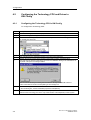
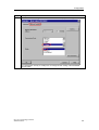
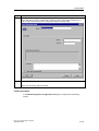
Configuring the Technology CPU and Drives in HW Config.............................4-2
Configuring the Technology CPU in HW Config ...............................................4-2
I/O address areas of the integrated technology ................................................4-5
Configuring drives in HW Config .......................................................................4-6
Selecting the telegram type...............................................................................4-9
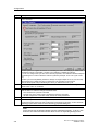
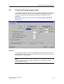
Using Technology Objects Management ........................................................4-11
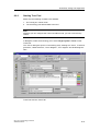
Starting Technology Objects Management.....................................................4-11
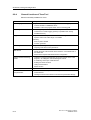
Technology Objects Management, user interface ..........................................4-12
Technology Objects Management, operating .................................................4-13
Creating and managing technology DBs ........................................................4-14
Using S7T Config ............................................................................................4-16
Starting S7T Config.........................................................................................4-16
The user interface of S7T Config ....................................................................4-17
Configuring axes .............................................................................................4-20
Adding a data record for data record changeover ..........................................4-29
Configuration - Axis.........................................................................................4-33
Mechanical settings of the axis and encoder ..................................................4-34
High resolution ................................................................................................4-36
Default .............................................................................................................4-37
Limits ...............................................................................................................4-39
Position and velocity .......................................................................................4-39
Hardware limit switches ..................................................................................4-40
Software limit switches ...................................................................................4-41
Dynamic response ..........................................................................................4-42
Fixed end stop ................................................................................................4-43
Homing ............................................................................................................4-45
Introduction .....................................................................................................4-45
Active homing .................................................................................................4-45
Passive/On-the-fly homing..............................................................................4-53
Direct homing..................................................................................................4-58
Position correction ..........................................................................................4-58
Traversing with a non-homed axis..................................................................4-59
Monitoring functions ........................................................................................4-60
Overview - Monitoring functions .....................................................................4-60
Positioning and standstill monitoring ..............................................................4-62
Dynamic following error monitoring ................................................................4-63
Standstill signal ...............................................................................................4-64
Synchronization monitoring ............................................................................4-65
Manipulated variable monitoring.....................................................................4-65
Control.............................................................................................................4-66
Position control ...............................................................................................4-66
Static controller data .......................................................................................4-66
Dynamic controller data ..................................................................................4-68
Friction compensation.....................................................................................4-69
CPU 317T: Technology Functions
A5E00251798-03
Contents
4.6
4.6.1
4.6.2
4.6.3
4.6.4
4.6.5
4.6.6
4.7
4.7.1
4.7.2
4.7.3
4.7.3.1
4.7.3.2
4.7.3.3
4.7.4
4.7.5
4.7.5.1
4.7.5.2
4.8
4.8.1
4.8.2
4.8.3
4.9
4.9.1
4.9.2
4.10
4.10.1
4.10.2
4.10.3
4.10.4
4.11
5
Configuring synchronization axes ...................................................................4-70
Assigning leading axes and cam disks ...........................................................4-72
Configuring superimposing synchronism ........................................................4-73
Synchronization...............................................................................................4-76
Synchronization...............................................................................................4-81
Desynchronization...........................................................................................4-85
Monitoring functions ........................................................................................4-86
Configuring cam disks.....................................................................................4-87
Inserting a cam disk ........................................................................................4-88
Defining cam disks ..........................................................................................4-90
Creating cam disks with CamEdit ...................................................................4-91
Interpolation ....................................................................................................4-92
Interpolation (2)...............................................................................................4-95
Scaling ............................................................................................................4-96
Creating cam disks with CamTool ..................................................................4-98
Motion laws to VDI ..........................................................................................4-99
Working ranges and motion transitions ..........................................................4-99
Defining cam disk segments for motion control commands .........................4-101
Configuring cams ..........................................................................................4-102
Inserting cams...............................................................................................4-102
Configuration .................................................................................................4-104
Highspeed cams ...........................................................................................4-105
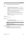
Configuring measuring sensors ....................................................................4-106
Adding a measuring sensor ..........................................................................4-106
Configuration - Measuring Sensor ................................................................4-108
Configuring external encoders ......................................................................4-109
Inserting an External Encoder.......................................................................4-109
Configuration - External Encoder ..................................................................4-119
Mechanical Settings - External Encoder .......................................................4-120
Default - External Encoder ............................................................................4-121
Copying configuration data of another station ..............................................4-122
Programming
5.1
5.2
5.3
5.4
5.5
5.6
5.7
5.8
5.9
5.10
5-1
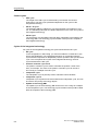
Time model........................................................................................................5-1
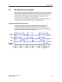
Runtime and programming model.....................................................................5-6
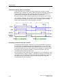
Monitoring busy commands ..............................................................................5-9
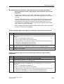
Errors and warnings at the technology function..............................................5-11
Errors at the MCDevice & Trace technology DBs...........................................5-12
Errors and warnings at the axes & external encoders technology DB ...........5-13
Errors and warnings at the cam disk & measuring sensor & output cam
technology DB .................................................................................................5-14
Behavior of Virtual Axes..................................................................................5-15
Symbolic programming with FC 400 "DB2INT"...............................................5-16
Programming axis-specific parameter changes..............................................5-17
CPU 317T: Technology Functions
A5E00251798-03
ix
Contents
6
Technology functions
6.1
6.2
6.2.1
6.2.2
6.2.3
6.2.4
6.2.5
6.2.6
6.2.7
6.2.8
6.2.9
6.2.10
6.2.11
6.2.12
6.3
6.3.1
6.3.2
6.3.3
6.3.4
6.3.5
6.3.6
6.3.7
6.3.8
6.3.9
6.3.10
6.4
6.4.1
6.4.2
6.4.3
6.4.4
6.5
6.5.1
6.5.2
6.5.3
6.5.4
6.6
6.6.1
6.6.2
6.6.3
6.6.4
6.6.5
6.6.6
6.6.7
6.6.8
6.6.9
x
6-1
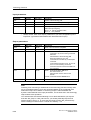
Overview ...........................................................................................................6-1
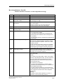
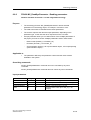
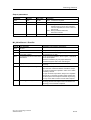
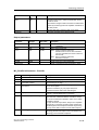
Technology functions - Single axis ...................................................................6-3
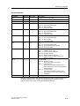
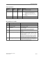
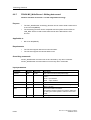
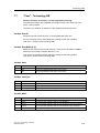
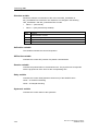
FB 401 MC_Power - Enable / disable axis .......................................................6-3
FB 403 MC_Home - Axis homing / setting......................................................6-11
FB 404 MC_Stop - Stop axes / prevent new motion commands ....................6-19
FB 405 MC_Halt - Normal stop .......................................................................6-25
FB 409 MC_ChangeDataset - Changing the data set ....................................6-31
FB 410 MC_MoveAbsolute - Absolute positioning .........................................6-37
FB 411 MC_MoveRelative - Relative positioning ...........................................6-52
FB 412 MC_MoveAdditive - Additive positioning to current target position....6-67
FB 413 MC_MoveSuperImposed - Superimposed positioning.......................6-73
FB 414 MC_MoveVelocity - Moving with speed preset ..................................6-79
FB 415 MC_MoveToEndPos - Move to mechanical end stop / clamping ......6-90
FB 437 MC_SetTorqueLimit - Enable / disable torque reduction ...................6-97
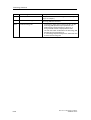
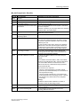
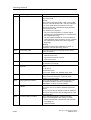
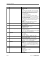
Technology functions - Synchronism ............................................................6-101
FB 420 MC_GearIn - Start gear synchronization..........................................6-101
FB 422 MC_GearOut - End gear synchronization ........................................6-111
FB 421 MC_CamIn - Start cam synchronization...........................................6-116
FB 423 MC_CamOut - End cam synchronism..............................................6-132
FB 424 MC_Phasing - Change phase shift between master
and slave axes ..............................................................................................6-137
FB 441 MC_CamInSuperImposed Start superimposing cam synchronism .........................................................6-142
FB 443 MC_CamOutSuperImposedTerminate superimposing cam synchronism ................................................6-151
FB 440 MC_GearInSuperImposed Start superimposing gear synchronism.........................................................6-155
FB 442 MC_GearOutSuperImposed Terminate superimposing gear synchronism ................................................6-166
FB 444 MC_PhasingSuperImposed - Change superimposing phase shift ..6-170
Technology functions - Cam disks ................................................................6-177
FB 434 MC_CamClear - Deleting cams........................................................6-177
FB 435 MC_CamSectorAdd - Adding cam segments ..................................6-180
FB 436 MC_CamInterpolate - Interpolating cams.........................................6-187
FB 438 MC_GetCamPoint - Reading points from the cam disk ...................6-192
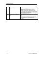
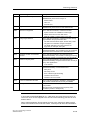
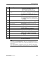
Technology functions - Cams, measuring sensors, external encoders ........6-196
FB 430 MC_CamSwitch - Position-based cam.............................................6-196
FB 431 MC_CamSwitchTime - Time-based cam..........................................6-200
FB 433 MC_MeasuringInput - Measuring sensor .........................................6-203
FB 432 MC_ExternalEncoder - External encoder.........................................6-207
Technology functions - Basic functions.........................................................6-211
FB 402 MC_Reset - Error acknowledgement ...............................................6-211
FB 406 MC_ReadSysParameter - Reading parameters ..............................6-215
FB 407 MC_WriteParameter - Changing parameters...................................6-218
FB 450 MC_ReadPeriphery - Reading technology I/O .................................6-226
FB 451 MC_WritePeriphery - Writing technology I/O ...................................6-231
FB 453 MC_ReadRecord - Reading data record..........................................6-236
FB 454 MC_WriteRecord - Writing data record ............................................6-240
FB 455 MC_ReadDriveParameter - Reading drive parameters ...................6-244
FB 456 MC_WriteDriveParameter - Writing drive parameters......................6-248
CPU 317T: Technology Functions
A5E00251798-03
Contents
6.7
6.7.1
6.7.2
6.7.3
6.7.4
7
Technology DBs
7.1
7.2
7.3
7.4
7.5
7.6
7.7
7.8
7.9
7.10
7.11
7.11.1
7.11.2
7.11.3
7.11.4
7.11.5
7.11.6
7.11.7
8
Information about parameters .......................................................................6-253
Reaction of the technology function after POWER OFF and restart ............6-253
DoneFlag generation.....................................................................................6-253
Range of values ............................................................................................6-254
Absolute positioning of modulo axes ............................................................6-255
"Velocity-controlled axis" - Technology DB.......................................................7-1
"Positioning axis" - Technology DB...................................................................7-5
"Synchronization axis" - Technology DB.........................................................7-10
"External encoder" - Technology DB ..............................................................7-16
"Cam disk" - Technology DB...........................................................................7-20
"Measuring sensor" - Technology DB .............................................................7-21
"Cam" - Technology DB ..................................................................................7-23
"Trace" - Technology DB.................................................................................7-25
"MCDevice" - Technology DB .........................................................................7-26
Update of technology DBs ..............................................................................7-28
ErrorID - Technology DBs ...............................................................................7-30
ErrorIDs - Axis technology DBs.......................................................................7-36
ErrorIDs - Synchronization technology DB .....................................................7-36
ErrorIDs - External encoders technology DB ..................................................7-44
ErrorIDs - Output cam technology DB ............................................................7-49
ErrorIDs - Measuring sensor technology DB ..................................................7-52
ErrorIDs - Cam technology DBs......................................................................7-55
ErrorIDs - MCDevice / Trace technology DB ..................................................7-58
Download, testing and diagnostics
8.1
8.2
8.3
8.4
8.5
8.6
8.7
8.8
8.8.1
8.8.2
8.8.3
8.8.4
8.8.5
8.8.6
8.8.7
8.8.8
8.8.9
8.8.10
8.8.11
8.8.12
8.8.13
8.8.14
7-1
8-1
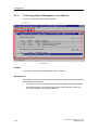
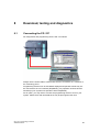
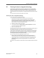
Connecting the PG / PC....................................................................................8-1
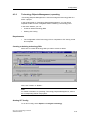
Downloading - user program, configuration data, firmware ..............................8-2
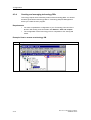
Tuning technology system cycles .....................................................................8-5
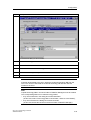
Assigning technology system cycles.................................................................8-8
Checking the load on integrated technology.....................................................8-9
Testing with breakpoints .................................................................................8-10
Monitoring system variables with the Watch table ..........................................8-11
Testing with TraceTool....................................................................................8-12
Introduction - TraceTool ..................................................................................8-12
Trace for SINAMICS drives.............................................................................8-12
Starting TraceTool...........................................................................................8-13
General functions of TraceTool.......................................................................8-14
Basic procedure for handling the TraceTool ...................................................8-15
The TraceTool toolbars ...................................................................................8-15
"Trace" menu...................................................................................................8-18
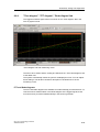
"Trace" tab.......................................................................................................8-20
"Time diagram", "FFT diagram", "Bode diagram"tab ......................................8-25
Tracing values of the user program in the CPU..............................................8-26
"Function generator" tab .................................................................................8-27
"Measurements" tab ........................................................................................8-31
"Trace time diagram" tab in the detail view.....................................................8-33
Further tools in the "Time diagram", "FFT diagram", "Bode diagram" tab ......8-33
CPU 317T: Technology Functions
A5E00251798-03
xi
Contents
8.9
8.9.1
8.9.2
8.9.3
8.9.4
8.9.5
8.9.6
A
Testing with the control panel .........................................................................8-36
Introduction - Control panel.............................................................................8-36
Starting the axis control panel.........................................................................8-37
Layout of the axis control panel ......................................................................8-37
Using the control panel to monitor axis values ...............................................8-39
Assume control priority....................................................................................8-40
Controlling the axis..........................................................................................8-41
Appendix
A.1
A.1.1
A.1.2
A.1.3
A.2
A.2.1
A.2.2
A.2.3
A.2.4
A.2.5
A.2.6
A.2.7
A.2.8
A.3
A.3.1
A.3.2
A.3.2.1
A.3.2.2
A.3.2.3
A.3.2.4
A.3.3
A.3.3.1
A.3.3.2
A.3.4
A.3.4.1
A.3.4.2
A.3.4.3
A.4
A.4.1
A.4.2
A-1
Application samples ......................................................................................... A-1
Example of "Positioning with target sensor" .................................................... A-1
Example of "Flying shears" .............................................................................. A-3
Example of "Gripper feed"................................................................................ A-5
FAQs, Tips & Tricks ......................................................................................... A-7
How to use the new performance features for older Technology CPUs.......... A-7
How to edit a V1.0 project with S7 technology V2.0 ...................................... A-15
How to recognize the firmware version of the integrated technology ............ A-16
Why do some system DBs have a different online / offline time stamp?....... A-17
Why does the number of system DBs differ in the online and offline view? .. A-17
STEP 7 reports "Out of memory space" ........................................................ A-18
The CPU goes into STOP sporadically as a result of time-out ...................... A-18
Errors occur when the "Save and compile all" function is executed
for the technology data................................................................................... A-18
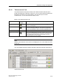
Expert list in S7T Config................................................................................. A-19
Using the Expert list ....................................................................................... A-19
Axis settings ................................................................................................... A-22
Commissioning the position controllers of positioning axes .......................... A-22
Assigning interpolator cycle 2 ........................................................................ A-23
Torque settings .............................................................................................. A-24
Setting actual value coupling at the synchronization object .......................... A-25
External encoder settings............................................................................... A-27
Setting the standstill signal............................................................................. A-27
External encoder - Synchronization with incremental encoders .................... A-27
Monitoring functions ....................................................................................... A-30
Encoder monitoring functions......................................................................... A-30
Encoder limit frequency monitoring................................................................ A-30
Velocity error monitoring ................................................................................ A-31
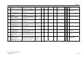
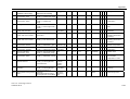
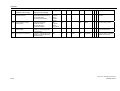
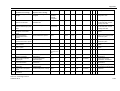
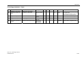
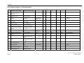
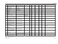
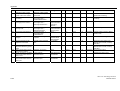
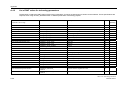
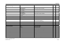
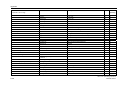
Technology parameters ................................................................................. A-32
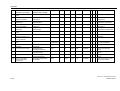
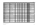
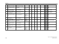
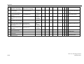
List of technology parameters ........................................................................ A-32
List of DINT values for technology parameters.............................................. A-56
Index
xii
CPU 317T: Technology Functions
A5E00251798-03
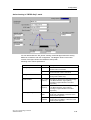
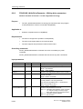
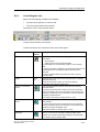
1
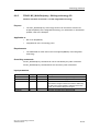
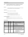
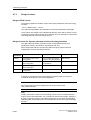
What's new in S7-Technology V2.0
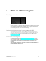
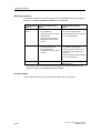
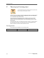
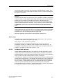
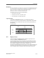
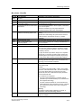
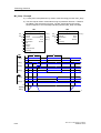
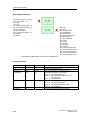
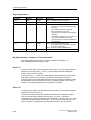
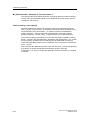
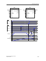
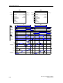
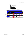
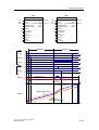
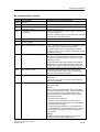
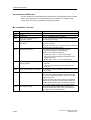
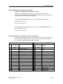
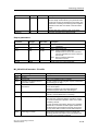
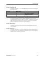
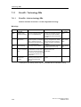
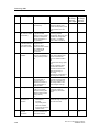
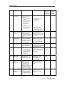
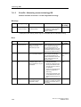
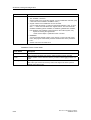
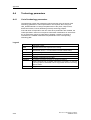
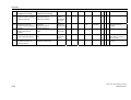
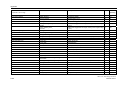
Extended project data volume
S7
V1.0
V2.0
Axes
16
32
Cam disks
16
32
Output cam
16
32
Measuring input
4
16
External encoders
4
16
Further information on project data volume and operating conditions are found here
This extended project data volume is available after you upgrade the firmware of
the Technology CPU and of the integrated technology.
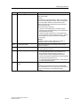
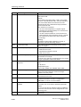
Synchronous technology processing in the user program with OB65
The technology synchronization interrupt OB65 a technology interrupt which is
called and processed synchronously to the update of technology DBs. OB65 can
be used to evaluate current and consistent data of technology DBs (see also
Technology DB updates ).
Encoder / data record changeover
S7-Technology V2.0 supports encoder and data record changeover in runtime.
You can use the encoder changeover function to determine the material position,
for example, the axes in position, in systems containing several actual value
encoders.
Use data record changeover to modify axis parameters (controller parameters, for
example) when the system is in run.
CPU 317T: Technology Functions
A5E00251798-03
1-1
What's new in S7-Technology V2.0
Use of DP(DRIVE) for standard DP slaves (V0)
DP(DRIVE) supports only standard DP slaves (V0). DP standard slaves (V0) can
be mapped to the I/O image DP(DRIVE) of the integrated technology, and
evaluated using the technology functions "MC_ReadPeriphery" and
"MC_WritePeriphery".
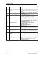
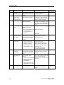
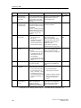
Enhanced functions for stand-alone axes
MC_MoveAbsolute MC_MoveRelative, MC_MoveVelocity
At the new Mode input parameter, you can decide whether to override the active
motion, or to continue with the new motion after a stop, or to overlay it with the new
speed.
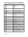
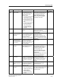
New and enhanced functions for synchronism
•
MC_GearIn
The new input parameter PhaseShift can be used to set a phase shift between
a master and following axis.
•
MC_Phasing
The technology function is now also available for gearing.
New superimposing synchronization functions
These new superimposing synchronization functions can be used to process parts
on-the-fly.
•
MC_CamInSuperImposed, MC_CamOutSuperImposed
The technology functions "MC_CamInSuperImposed" and
"MC_CamOutSuperImposed" start or end superimposing camming between
the leading and following axes.
•
MC_GearInSuperImposed, MC_GearOutSuperImposed
The technology functions "MC_GearInSuperImposed" and
"MC_GearOutSuperImposed" start or end superimposing gearing between the
leading and following axes.
•
MC_PhasingSuperimposed
Use the technology function "MC_PhasingSuperImposed" to define a phase
shift of the leading axis to the following axis in the coordinate system of
superimposing synchronism.
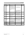
New and improved cam disk function
1-2
•
MC_GetCamPoint
The new technology function "MC_GetCamPoint" allows you to determine the
position of the leading and following axes at an existing cam disk.
•
MC_CamSectorAdd
The performance of the technology function "MC_CamSectorAdd" with respect
to the insertion of interpolation points was significantly improved.
CPU 317T: Technology Functions
A5E00251798-03
What's new in S7-Technology V2.0
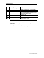
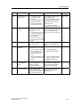
New and enhanced basic functions
•
MC_Reset
It is now possible to restart based on a specific cam disk. The restart function
restores the cam disk originally configured in S7T Config. During the restart of
a technology object, the system continues to process new commands output to
other technology objects.
•
MC_ReadSysParameter
The new input parameter Index allows read access to multiple instances of a
parameter.
In combination with the new functionality of MC_WriteParameter, the user can
now save a backup copy of the data of an absolute value encoder adjustment
in preparation for a CPU replacement.
•
MC_WriteParameter
The new Index input parameter can be used to write to several instances of
parameter sets / data records.
In combination with the new functionality of MC_ReadParameter, the user can
now save a backup copy of the data of an absolute value encoder adjustment
in preparation for a CPU replacement.
•
MC_ReadPeriphery, MC_WritePeriphery
The new technology functions "MC_ReadPeriphery" and "MC_WritePeriphery"
provide read / write access to the I/O image DP(DRIVE) of the integrated
technology. This functionality allows you to write the I/O image of a standard
slave connected to DP(DRIVE) to the I/O image DP(DRIVE) of the integrated
technology, for example.
•
MC_ReadDriveParameter, MC_WriteDriveParameter
The new technology functions "MC_ReadDriveParameter" and
"MC_WriteDriveParameter" provide read / write access to the parameters of a
drive connected to DP(DRIVE).
Operating SINAMICS Terminal Modules TM15 and TM17 High Feature in
combination with the SINAMICS S120 system
S7-Technology V2.0 supports the operation of SINAMICS Terminal Modules TM15
and TM17 High Feature in combination with the SINAMICS S120 system. The
Terminal Modules can be used as measuring sensor inputs and (high speed) cam
outputs.
Order numbers are found under "Available components and systems."
CPU 317T: Technology Functions
A5E00251798-03
1-3
What's new in S7-Technology V2.0
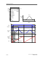
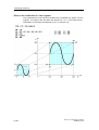
Comfortable cam disk programming using the optional SCOUT CamTool
S7-Technology V2.0 supports the optional SCOUT CamTool V2.1 SP1. The
SCOUT CamTool offers the following benefits:
•
Precise, graphic visualization of the cam
•
Quick and easy cam definition by means of drag-and-drop of cam elements
•
Quick and easy cam tuning by means of "dragging at the profile"
•
Simultaneous visualization of the position, velocity, acceleration and jerk profile
has an immediate effect on the maximum velocity, the motor torque required
and on mechanical load.
•
Tuning the velocity, acceleration or jerk parameters of the cam
Order numbers are found under "Available components and systems."
1-4
CPU 317T: Technology Functions
A5E00251798-03
2
Application and usage
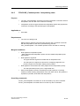
2.1
Compact and integrated
The Technology CPU integrates Motion Control functions into a SIMATIC CPU,
and thus combines the functionality of a SIMATIC S7-300 CPU with
PLCopen-compliant Motion Control functions.
The Technology CPU is totally integrated into the SIMATIC system, and thus into
the TIA environment. It demonstrates its high performance in particular in the field
of coupled motion operations.
2.2
The familiar "SIMATIC world"
The Technology CPU is a standard SIMATIC CPU, with integrated Motion Control
functionality. S7-300 programs of existing projects can thus be copied to this CPU.
The Technology CPU is programmed in the SIMATIC programming languages, for
example, LAD/FBD/STL.
All PLC and Motion Control functions are executed in a single user program. Three
is no need to learn any additional programming language, because users can rely
on their current S7 know-how.
The technology system is configured in the user-friendly environment of STEP 7
with the help of S7T Config. There you set up all your system essentials, such as
the mechanical data, drives, control circuits, default values, monitoring functions,
cams, measuring sensors, cam disks, and lots more.
CPU 317T: Technology Functions
A5E00251798-03
2-1
Application and usage
2.3
Integrated PLCopen-compliant motion control
functions in STEP 7
The PLCopen-compliant Motion Control functions of your Technology CPU let you
to directly utilize your Motion Control know-how. The interfaces, functions and
runtime of Motion Control are fully compliant with PLCopen specifications. This is a
great help for accomplishing your engineering, commissioning and service tasks.
The standardized interface allows a virtually seamless integration of function blocks
for initiating motion control commands into the user program.
2.4
Available components and systems
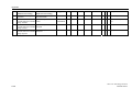
Valid for firmware version V3.1.x of the integrated technology
SIMATIC Technology CPU / software
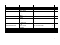
Components required to use a SIMATIC Technology CPU:
Function
Product
Order number
SIMATIC Technology CPU
CPU 317T-2DP
6ES7317-6TJ10-0AB0
Micro Memory Card
MMC 4 MB (or more)
6ES7953-8LM11-0AA0
Optional "S7-Technology"
software package
SIMATIC S7-Technology V2.0 6ES7864-1CC20-0YX0
STEP 7
STEP 7 V5.3 SP1
6ES7810-4CC07-0Yxx
In addition to the optional "S7-Technology" software package, you can also use the
software product shown below:
2-2
Function
Product
Order number
SCOUT CamTool
SCOUT CamTool V2.1
6AU1810-0FA21-0XA0
CPU 317T: Technology Functions
A5E00251798-03
Application and usage
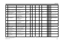
PROFIBUS DP(DRIVE)
Components for technological tasks operating in synchronized mode on
DP(DRIVE), valid at the time this manual was released for printing:
Product
Order number
SIMODRIVE
SIMODRIVE
611 universal
6SN1118-XN00-0AAx
SIMODRIVE
611 universal HR
6SN1114-0NB0X-0AAx
Optional module Motion Control with PROFIBUS
DP
(for SIMODRIVE 611U)
6SN1114-0NB01-0AA0
SIMODRIVE POSMO CA
6SN2703-3AAx
SIMODRIVE POSMO CD
6SN2703-2AAx
SIMODRIVE POSMO SI
6SN24x
SIMODRIVE sensor single-turn / synchro-flange
6FX2001-5FP12
SIMODRIVE sensor, single-turn / clamping flange
6FX2001-5QP12
SIMODRIVE sensor multi-turn / synchro-flange
6FX2001-5FP24
SIMODRIVE sensor multi-turn / clamping flange
6FX2001-5QP24
MICROMASTER 4
COMBIMASTER 411
6ES6401-0PB00-0AA0
MICROMASTER 420
6ES6400-1PB00-0AA0
MICROMASTER 430
6ES6400-1PB00-0AA0
MICROMASTER 440
6ES6400-1PB00-0AA0
MASTERDRIVES
with communication module CBP2
Motion Control
6SE7090-0XX84-0FF5
Motion Control Plus
6SE7090-0XX84-0FF5
Vector Control CUVC
6SE7090-0XX84-0FF5
Vector Control Plus
6SE7090-0XX84-0FF5
Note the order number suffix "Gxx" for
communication module CBP2 when placing your
order.
SINAMICS
SINAMICS S120
6SL3040-0MA00-0AAx
Terminal Module TM15 *
6SL3055-0AA00-3FA0
Terminal Module TM17 High Feature *
6SL3055-0AA00-3HA0
SINUMERIK
ADI4
6FC5211-0BA01-0AA1
SIMATIC ET 200M **
IM 153-2 High Feature
6ES7153-2BA00-0XB0
SM 331 AI8x14Bit
6ES7331-7FH00-0AB0
SM 331 AI8x14Bit
6ES7331-7FH01-0AB0
SM 321 DI16xDC24V
6ES7321-1BH01-0AA0
SM 321 DI16xDC24V, Alarm
6ES7321-7BH01-0AB0
SM 322 DO16xDC24V/0,5A
6ES7322-1BH10-0AA0
CPU 317T: Technology Functions
A5E00251798-03
2-3
Application and usage
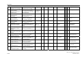
Product
Order number
SIMATIC ET 200S **
*
IM 151-1 High Feature
6ES7151-1BA00-0AB0
2AI I 2WIRE HS
6ES7134-4GB51-0AB0
2AI I 4WIRE HS
6ES7134-4GB61-0AB0
2AI U HS
6ES7134-4FB51-0AB0
2DI DC24V HF
6ES7131-4BB00-0AB0
4DI UC24..48V
6ES7131-4CD00-0AB0
4DI DC24 HF
6ES7131-4BD00-0AB0
2DO DC24V/0,5A HF
6ES7132-4BB00-0AB0
2DO DC24V/0,2A HF
6ES7132-4BB30-0AB0
4DO DC24V/0,5A ST
6ES7132-4BD00-0AA0
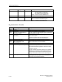
For additional high-speed cams, hardware limit switches and measuring
sensors.
** For additional cams and hardware limit switches.
Components configurable in HW Config are listed in the "Hardware catalog" dialog
box of HW Config. To do so, select the "SIMATIC Technology CPU" profile in
HW Config.
The current component list is always found in the latest SW version, provided your
S7-Technology is updated to this version.
DP-V0 slaves on DP(DRIVE)
In addition to ET 200M and ET 200S, you can operate further I/O as DP-V0 slave
on DP(DRIVE). However, some restrictions apply.
Interrupts are not available, i.e. DP-V0 slaves can not be operated in continuous
synchronized mode on DP(DRIVE), and longer response times are to be expected.
Positioning drive POSMO A
A positioning drive POSMO A can be operated on the DP/MPI segment of the
317T-2 DP CPU. It is implemented by means of special FBs of the
"Posmo A Library". Posmo A library is not available for DP(DRIVE).
Product
Order number
SIMODRIVE POSMO A
6SN21x
Hardware and software requirements
For information on HW and SW requirements for using the "S7-Technology V2.0"
optional package, refer to Readme.wri on your product CDROM.
2-4
CPU 317T: Technology Functions
A5E00251798-03
Application and usage
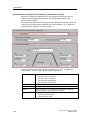
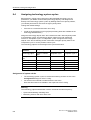
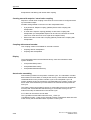
2.5
Project data volume and operating conditions
Valid for firmware version V3.1.x of the integrated technology
When you plan your Motion Control tasks, make allowances for the following
project data volume and operating conditions listed.
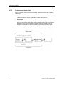
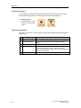
Project data volume (CPU 317T)
•
32 axes (virtual or physical)
•
32 cams
Eight cams can be output as "high-speed cams" at the integrated outputs of the
Technology CPU. A further 24 cams can be implemented via distributed I/O
(ET 200M or ET 200S, for example.) These cams can be integrated as "highspeed cams" at the TM15 and TM17 High Feature.
•
32 cam disks
•
16 measuring sensors
•
16 external encoders
Note
The maximum number of technology objects (TOs) may not exceed 64. 18 axes,
22 cam disks, 18 cams, 5 measuring sensors, 1 external encoder = 64 TOs, for
example.)
Operating conditions
•
The system can be configured using S7-Technology V2.0 and
STEP 7 V5.3 + SP1 or higher.
•
All HW components required by the integrated technology must be connected
to DP(DRIVE).
•
In the user program, you can address up to 64 bytes of input and 64 bytes of
output data of the integrated technology. Inputs and outputs available:
-
4 integrated inputs of the Technology CPU
The integrated inputs can be used either for analysis functions in the user
program, or for technological tasks. Mixed mode is not possible.
-
8 integrated outputs of the Technology CPU
(exclusive use as with integrated inputs)
-
Inputs and outputs of distributed I/O on DP(DRIVE)
•
Distributed I/O not required by the integrated technology should preferably be
connected to the MPI/DP interface of the Technology CPU.
•
Programming devices, text-based displays and OPs may not be operated on
DP(DRIVE).
•
Up to 210 Motion Control commands can be active simultaneously.
•
The typical cycle time of technology functions in the user program is 80 µs.
CPU 317T: Technology Functions
A5E00251798-03
2-5
Application and usage
2.6
Components and their tasks
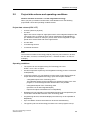
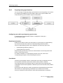
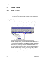
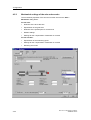
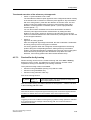
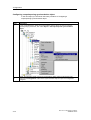
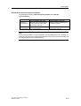
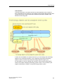
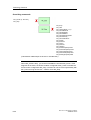
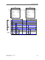
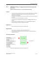
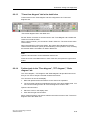
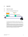
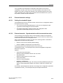
2.6.1
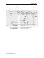
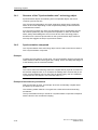
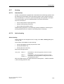
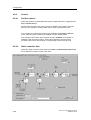
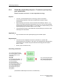
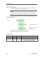
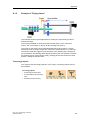
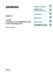
Hardware components
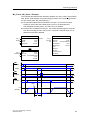
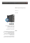
The hardware components of a Motion Control solution with a Technology CPU are
shown in the figure below:
Control elements and integrated technology
The control unit of the Technology CPU can handle all tasks of a standard CPU of
the S7-300 family. The integrated technology controls, evaluates and monitors all
hardware components which are connected to DP(DRIVE), and are required for
solving Motion Control tasks. The Technology CPU is equipped with four integrated
digital inputs and eight digital outputs which should be used primarily for Motion
Control tasks.
MPI/DP
At the MPI/DP interface of the PLC, you can operate standard PROFIBUS
components such as programming devices, text-based displays, operator panels
and DP field devices.
2-6
CPU 317T: Technology Functions
A5E00251798-03
Application and usage
DP(DRIVE)
The 317T-2 DP CPU operates the PROFIBUS interface DP(DRIVE) in clocksynchronized mode. All HW components addressed by the integrated technology
must be present on the DP(DRIVE) system. This includes component of the
MICROMASTER, SIMODRIVE, MASTERDRIVES, SINAMICS families and the
SIMODRIVE Sensor.
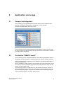
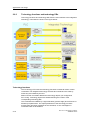
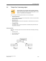
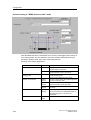
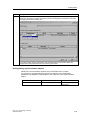
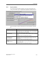
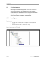
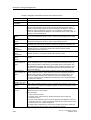
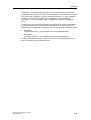
2.6.2
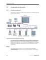
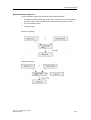
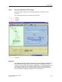
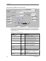
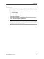
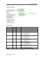
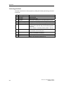
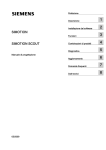
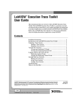
Engineering tools
Motion Control applications are always configured and programmed in STEP 7.
The figure below shows you the various tools available for configuring your Motion
Control application.
SIMATIC STEP 7
STEP 7 is the platform for configuring and programming the Technology CPU.
All engineering tools required are called in SIMATIC Manager of STEP 7.
CPU 317T: Technology Functions
A5E00251798-03
2-7
Application and usage
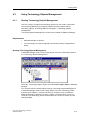
SIMATIC S7-Technology
SIMATIC S7-Technology is an optional software package you need to configure
Motion Control functionality of your Technology CPU. Setup fully integrates
SIMATIC S7-Technology into the STEP 7 system. Setup installs the following tools
alongside with S7-Technology:
•
Technology Objects Management
•
S7-Tech library
•
S7T Config, including STARTER
LAD/FBD/STL
You program the user program and Motion Control commands in the
LAD/FBD/STL block editor. In your user program, read out the actual values of
your Motion Control application, and analyze the messages and error information.
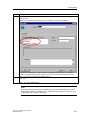
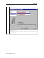
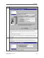
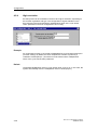
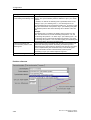
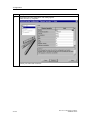
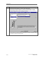
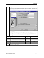
Technology Objects Management
You create and delete technology DBs in "Technology Objects Management." You
also use "Technology Objects Management" to rename technology DBs, or assign
different block numbers.
S7-Tech library
S7-Tech is a library of PLCopen-compliant technology functions you call in the user
program as FB. These are used to control your Motion Control commands.
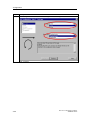
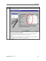
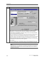
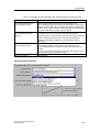
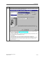
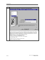
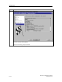
S7T Config
In S7T Config, you configure the technology objects you require to solve your
Motion Control task. S7T Config contains the STARTER code for drives of the
MICROMASTER and SINAMICS family.
CamTool (optional)
SCOUT CamTool can be ordered separately and can be used to create cam disks
on a comfortable graphic interface.
HW Config
HW Config is used to configure the hardware of your Technology CPU, and the
subnets connected to DP/MPI and DP(DRIVE) interfaces.
Drive ES Basic / SimoCom U / DriveMonitor
The optional Drive ES Basic and/or the stand-alone tools SimoCom U
(SIMODRIVE) or DriveMonitor (MASTERDRIVE) software packages can be used
to commission the drives.
2-8
CPU 317T: Technology Functions
A5E00251798-03
Application and usage
Technology DBs
Technology DBs can be used in the user program to read the actual data of
technology objects such as the actual values and status of an axis, or error
information.
Technology functions
The PLCopen-compliant technology functions are called in the user program of the
PLC. Technology functions form the command interface to technology objects. The
output parameters of technology functions can be made available in the user
program to control the status of Motion Control tasks.
Technology objects
Physical drives are mapped to technology objects which describe their properties.
Each technology object is maps itself to a technology DB in the STEP 7 user
program where it indicates its status. Technology objects can be interconnected
and logically linked to hardware components. All technology objects such as axes,
cam disks, cam runners, measuring sensors or external encoders are configured in
S7T Config.
CPU 317T: Technology Functions
A5E00251798-03
2-9
Application and usage
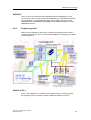
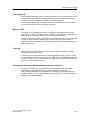
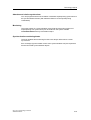
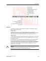
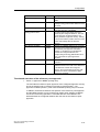
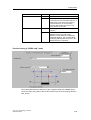
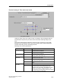
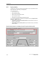
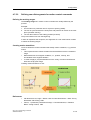
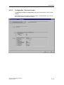
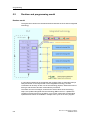
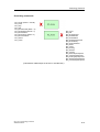
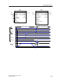
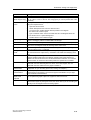
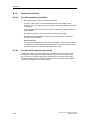
2.6.3
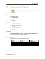
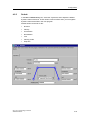
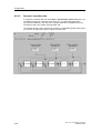
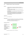
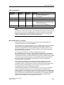
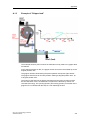
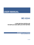
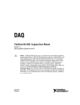
Technology functions and technology DBs
Technology functions and technology DBs form the user interface to the integrated
technology. Their tasks are shown in the figure below:
Technology functions
The Technology CPU uses the technology functions to initiate all motion control
commands. The integrated technology executes all commands in the order by
which they are initiated by the PLC.
Motion Control commands address the technology objects you configured in
S7T Config. Technology objects are addressed using the number of the
corresponding technology DB.
The commands are initiated by a signal transition (positive edge) at the Execute or
Enable input parameters. The output parameters of the technology functions
provide ready and abort messages of the command, or error messages if a
command could not be initiated.
2-10
CPU 317T: Technology Functions
A5E00251798-03
Application and usage
Technology DB
The integrated technology writes the process values of the technology object to the
assigned technology DB. This includes status and error messages output during
command execution and are also written to the technology DB.
The technology DBs of the automation system are not always retentive and writeprotected, irrespective of their set object properties.
MCDevice DB
The status of the integrated technology is mapped to the MCDevice technology
DB. This DB contains information on the maximum and average execution times of
Motion Control commands and errors in the integrated technology.
In addition, MCDevice offers you the option of indicating the status of the integrated
I/O and 32 done messages (DoneFlags) of some of the technology functions.
Define which done messages are indicated at the DoneFlag input parameter of the
technology function.
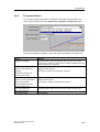
Trace DB
The TraceTool function of S7T Config is tool for the graphic analysis of system
parameters and process values.
In addition to the system parameters of the integrated technology, you can record
up to 8 variables of the S7 user program (2 x DINT values, 2 x DWORD values and
4 x REAL values.). Here, the Trace technology DB forms the interface between the
PLC and the integrated technology.
The ReadSysParameter / WriteParameter technology functions
It may prove necessary to temporarily change configuration data and system
variables of the integrated technology while the system is in RUN. The
"MC_ReadSysParameter" technology function reads the configuration data and
system variables, and "MC_WriteParameter" overwrites these. Changes at these
parameters are non-retentive.
CPU 317T: Technology Functions
A5E00251798-03
2-11
Application and usage
2-12
CPU 317T: Technology Functions
A5E00251798-03
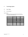
3
Technology objects
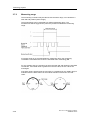
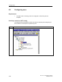
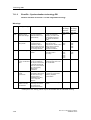
3.1
Axes - Basics
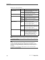
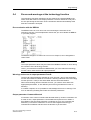
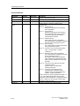
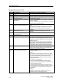
3.1.1
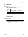
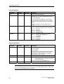
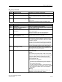
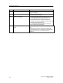
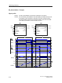
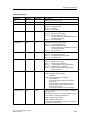
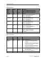
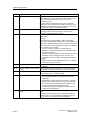
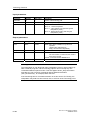
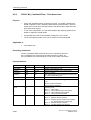
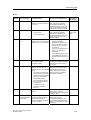
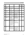
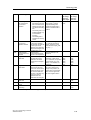
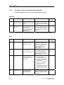
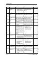
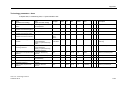
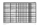
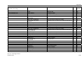
Axis technologies
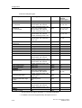
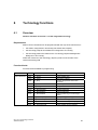
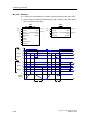
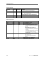
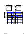
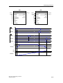
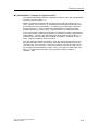
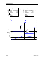
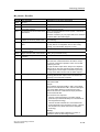
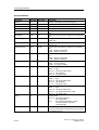
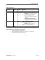
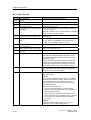
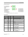
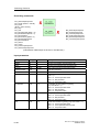
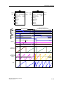
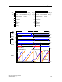
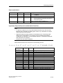
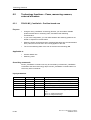
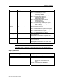
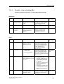
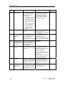
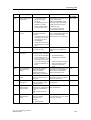
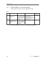
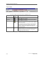
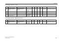
Axis technologies
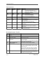
The "Axis" technology object can be configured as "Velocity-controlled axis",
"Positioning axis" or "Synchronization axis". The various axis technologies differ
according to the functions provided at the axis.
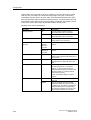
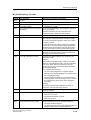
Function
Velocitycontrolled axis
Positioning axis
Synchronization
axis
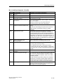
Changeover of the data record X
X
X
RPM or velocity preset
X
X
X
Motion with torque reduction
X
X
X
Positioning
-
X
X
Moving to fixed end stop
-
X
X
Homing
-
X
X
-
X
X
Advanced functions
Measuring input
Cam
-
X
X
Synchronized motion (gear,
cam)
-
-
X
Superimposed synchronized
motion (gear / cam)
-
-
X
CPU 317T: Technology Functions
A5E00251798-03
3-1
Technology objects
Special operating modes
•
Following mode
In following mode, the position / velocity controllers of the drive are disabled.
Inherent motions or dynamic breaking is not possible at the axis. The actual
position value and the velocity setpoint are updated. This allows you to detect
external triggering of axis motions.
Following mode is not possible at virtual axes.
•
Simulation mode
The simulation mode is used to test the programmed sequences in the PLC
without moving the axis in the process, based on Trace recordings.
This mode is only available for physical axes.
In simulation mode, all axes must be connected and fully functional. An axis is
simulated internally by setting the actual values equal to the setpoint values. In
simulation mode, the following error is always zero.
3-2
CPU 317T: Technology Functions
A5E00251798-03
Technology objects
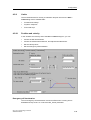
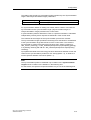
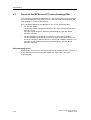
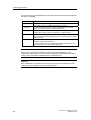
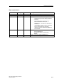
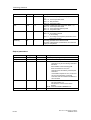
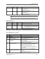
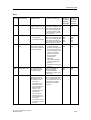
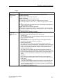
3.1.2
Axis types
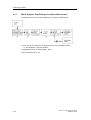
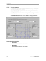
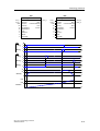
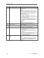
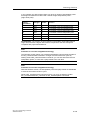
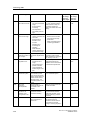
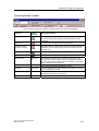
You can set two different types of axes in your axis configuration. The axis type
(linear or rotary, each also as modulo axis) is in essence determined by
mechanical conditions and by the units in which the axis-specific variables are
computed, for example, the position or velocity.
•
Linear axes
Linear axes are usually configured where the traversing range is mechanically
limited. The position profile is linear within the traversing range. Basic physical
units of the motions are the length units such as millimeter.
•
Rotary axes
Rotary axes are usually configured for a rotary motion range. The traversing
range is not limited mechanically. Basic physical units of the motions are
rotatory units such as degrees. Rotary axes are usually also configured for
operation as modulo axis.
Linear and rotary axes can be configured for operation as modulo axes. In this
case, the axis position is defined (reference and actual values) within a range
which is determined by the modulo start value, as the low limit, and by the modulo
start value plus modulo length as high limit.
Example: A rotary axis with a traversing range from 0° to 360" has a modulo start
value of 0°, and a modulo length of 360°. The axis position is reset to 0° when it
exceeds its high limit of 360°. When it passes the low limit (0°), the axis position is
set to the modulo start value plus the modulo length (360°). The position profile is
linear within the modulo length.
Note
The position value increments continuously when linear or rotary axes are
operated as infinite axes driven only in one direction (axis not configured as
modulo axis). The variables representing the setpoint and actual position values
are of the data type REAL, at a resolution of 23 binary digits (mantissa). The effect
is, that the axis positioning accuracy deteriorates with increasing position values.
Hence, you should preferably use modulo axes for infinite axis mode, or reset the
position to zero at appropriate times.
CPU 317T: Technology Functions
A5E00251798-03
3-3
Technology objects
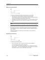
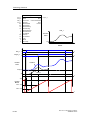
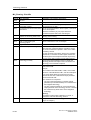
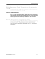
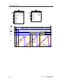
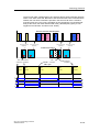
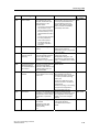
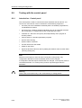
3.1.3
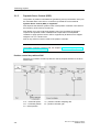
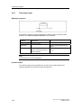
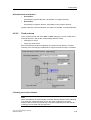
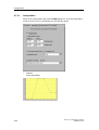
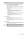
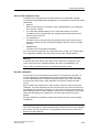
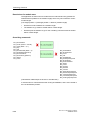
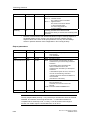
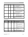
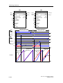
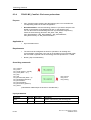
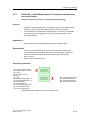
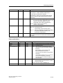
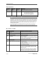
Physical and virtual axes
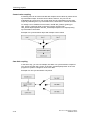
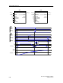
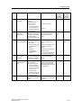
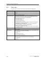
When we speak of axes in this documentation, we always refer to physical and
virtual axes.
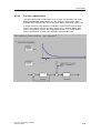
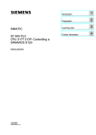
•
Physical axis
This axis features a motion control, drive and encoder interface
•
Virtual axis
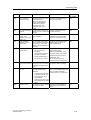
This axis features command variable generation, but does not have closedloop control or a drive or encoder interface Setpoint values and actual values
are always equal. The virtual axis is usually operated as auxiliary axis, for
example, to generate the reference values for several physical axes when
operated as leading axis in a synchronization compound.
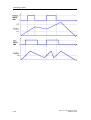
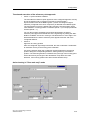
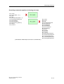
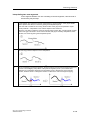
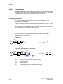
Difference between a physical and a virtual axis (example of a positioning axis)
3-4
CPU 317T: Technology Functions
A5E00251798-03
Technology objects
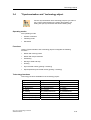
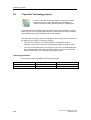
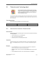
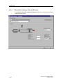
3.1.4
"Axis" - "drive" difference
The "Axis" technology object forms the interface between the user program and the
drive. It receives motion control commands from the user program in the PLC, and
then executes and monitors their runtime.
The axis communicates on the PROFIBUS with the drive that contains the velocity
and power controller.
Drives are configured and commissioned separately from the axis.
Functional interface to the drive
The Technology CPU supports operation of digital drives (SIMODRIVE 611
universal, MASTERDRIVES MC, for example) via DP(DRIVE) interface and analog
drives via ADI4. The interface between the technology object and the drive
component is here formed by a specified telegram which must be selected and
configured according to the functionality of each component.
These telegrams are used to exchange data between the PLC (technology object)
and the drive component (drive, for example). Example: control words, status
signals or encoder information.
Note
An axis can only execute the functions the connected drive actually supports.
Available functions, for example, operation with SIMODRIVE 611U or
MASTERDRIVES MC, are described in the converter documentation; see also the
relevant product descriptions.
CPU 317T: Technology Functions
A5E00251798-03
3-5
Technology objects
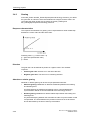
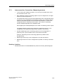
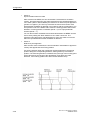
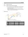
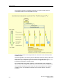
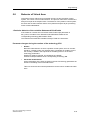
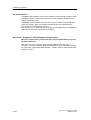
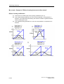
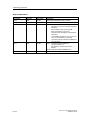
3.1.5
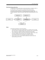
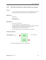
Dynamic Servo Control (DSC)
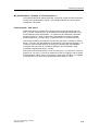
The position of position-controlled axes (positioning and synchronization axes) can
be controlled either in the CPU or in the drive, provided the control method
Dynamic Servo Control (DSC) is supported.
DSC imposes the effective dynamic action of the position controller in the drive on
the frequency of the velocity control loop.
DSC allows you to set a higher Kv sampling rate. This increases the dynamic
response to sequential control variables and compensation of manipulated
variables in highly dynamic drives. DSC is supported by all drives which support
telegram 5 or 6, or 105 and 106.
DSC is only useful in P-action mode of the position controller.
Note
The position controller must be tuned, see chapter "Commissioning the position
controllers of positioning axes".
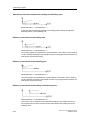
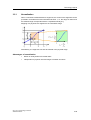
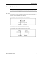
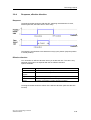
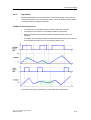
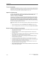
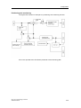
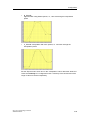
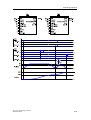
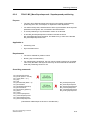
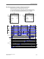
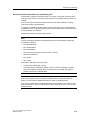
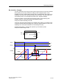
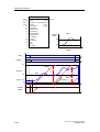
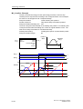
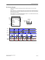
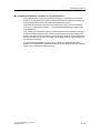
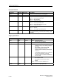
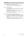
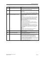
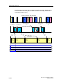
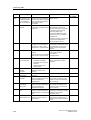
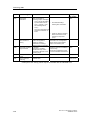
Position control loop without DSC
Structure of a position-control loop with the velocity setpoint interface to the drive
without DSC.
ncmd : command speed
xcmd : command position
xact : actual position
3-6
Tpc : position controller sampling rate
kpc : position controller gain
CPU 317T: Technology Functions
A5E00251798-03
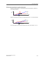
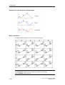
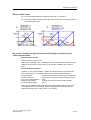
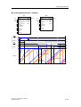
Technology objects
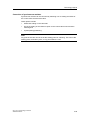
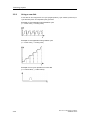
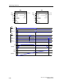
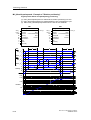
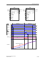
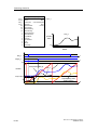
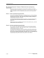
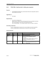
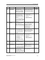
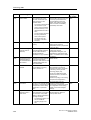
Position control loop with DSC
DSC functionality can also be used for direct derivative feedback of the actual
position calculated internally at the drive:
ncmd : command speed
xcmd : command position
xact : actual position
CPU 317T: Technology Functions
A5E00251798-03
Tpc : position controller sampling rate
kpc : position controller gain
3-7
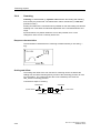
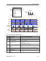
Technology objects
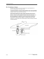
3.1.6
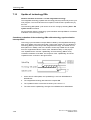
Homing
At position-controlled axes, input and indication of the position refer to the
coordinate system of the axis. The coordinate system of the axis must be aligned
to the physical position of the axis mechanism.
For incremental encoders, if you want to establish a direct reference to the position,
you must synchronize the actual value system of the axis after every activation.
Absolute value encoders must be adjusted once only.
Note
Whether motion commands with absolute destination coordinates can only be
executed in homed state is depends on the axis configuration.
Motion commands with relative position setting (MC_MoveRelative) can also be
executed with an axis that is not homed.
Axes retain their homed status when the CPU goes into stop.
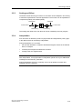
Incremental encoders are synchronized by means of the technology function
"MC_Home". This sets
•
the homing position coordinate, or
•
the homing coordinate minus the homing position offset for active homing
at a defined mechanical position of the axis.
The measurement of this defined mechanical position is triggered by the zero pulse
of the measuring system, or by a proximity switch (BERO.)
Note
After an axis is reinitialized (restart), it must be homed again when an incremental
measuring system is used.
3-8
CPU 317T: Technology Functions
A5E00251798-03
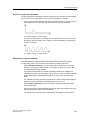
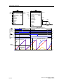
Technology objects
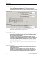
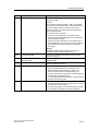
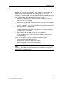
Homing modes
•
Active homing
A special traversing motion is executed for this type of homing. A currently
busy motion command is first canceled. The following homing modes can be
set in S7T Config:
•
-
Homing with BERO (homing output cam) and zero mark
-
Homing with BERO only
-
Homing with zero mark only.
Passive homing
The homing function does not trigger an axis motion in this case. Any busy
motion commands are not affected. Configurable homing modes:
•
-
Homing with BERO (homing output cam) and zero mark
-
Homing with BERO only
-
Homing with zero mark only.
Direct homing
The axis position is set regardless of homing cams (zero marks or BEROs).
When the axis is to be homed at a precise mechanical position, the axis must
be at a zero velocity during the process.
•
Adjusting the position value
An offset value is deducted from the current axis position value. Current
motions and homing are not influenced by this setting.
•
Correcting the internal axis coordinate system
An offset value is deducted from the actual position value of the base or
superimposing coordinate system. Current motions and homing are not
influenced by this setting.
Note
Device-specific properties
When homing with BERO and zero mark, the BERO can be connected to the
integrated inputs of the CPU or to a DP slave connected to DP(DRIVE).
When homing with BERO only, the BERO must be connected to the input device,
e.g. at the drive, at ADI4.
For further information on device-specific, marginal conditions and additional
parameter settings, refer to the supplementary information on SIMODRIVE 611U,
MASTERDRIVE-MC or ADI4 on the CD-ROM for your product and to the
equipment manuals.
CPU 317T: Technology Functions
A5E00251798-03
3-9
Technology objects
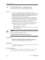
3.1.7
Absolute encoder adjustment
The technology functions MC_Home (Mode = 5) and MC_ExternalEncoder
(Mode = 6) are used to add the absolute value encoder offset for axis operation
and external encoders.
The current position of an axis with absolute value encoder is set to a required
value. This shifts (offsets) the absolute position of the absolute value encoder. This
offset is stored permanently and remains in effect for use in the next adjustment of
the absolute value encoder. Execute this function once when you commission the
PLC.
The offset is cleared if the Technology CPU changes from STOP to RUN and the
TO is invalid (for example, if the Technology CPU is started up without MMC.)
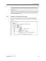
To adjust the absolute value encoder:
1. Disable the software limit switches, because otherwise you can not adjust the
absolute value encoders.
2. Move the axis to the relevant reference position, then adjust the absolute value
encoder (MC_Home or MC_ExternalEncoder technology function)
3. Enable the software limit switches as required.
Note that the adjustment of the absolute value encoder only offsets the encoder
value. The offset of the absolute value encoder adjustment and the value of the
absolute value encoder are decisive for determining the position after POWER
OFF or restart (MC_Reset, Restart = TRUE.) During operation, the current actual
position is also affected by the modulo settings of the axis, and by positioning or
position adjustment control commands.
Offset by absolute
value encoder
adjustment
(permanent)
Absolute
value
encoder
3-10
Correction in runtime
(MC_Home: Mode 3, 4)
Encoder position
Effective on
POWER ON
Actual position value
of the axis
CPU 317T: Technology Functions
A5E00251798-03
Technology objects
3.1.8
Data set changeover
Introduction
You can create several axis data records to change controller parameters or toggle
motor encoder mode to machine encoder mode while the system is in run, for
example.
The axes listed below support multiple data records:
•
Velocity-controlled axes
•
Positioning axes
•
Synchronization axes
Virtual axes support only one data record.
Configuration
Create a data record in the axis configuration dialog of S7T Config, and then
program it using the axis wizard. Use the "MC_ChangeDataset" technology
function to change the data record in RUN.
CPU 317T: Technology Functions
A5E00251798-03
3-11
Technology objects
3.2
"Velocity-controlled axis" technology object
Use the "Velocity-controlled axis" technology object if the axis
position is insignificant, i.e. if you only want to preset, control and
monitor the rpm or velocity of an axis.
Operating modes
Axis operating modes
•
Velocity-controlled
•
Simulation
•
Velocity preset
•
Motion with torque reduction
Functions
Technology functions
Technology functions available for the technology object:
3-12
MC_Power
MC_Reset
MC_Stop
MC_Halt
MC_MoveVelocity
MC_ReadSysParameter
MC_WriteParameter
MC_SetTorqueLimit
MC_ChangeDataset
CPU 317T: Technology Functions
A5E00251798-03
Technology objects
3.3
"Positioning axis" technology object
Use the positioning axis technology object to preset, control and
monitor the position of an axis.
Operating modes
Axis operating modes
•
Position-controlled
•
Following mode
•
Simulation
•
Motion with velocity preset
•
Motion with torque reduction
•
Positioning
•
Moving to fixed end stop
•
Homing
Functions
Positioning
In position-controlled mode, the axis is moved to a programmed target position.
The target position can be set "relative" or "absolute". You can specify the direction
of movement and the rotary direction of modulo axes.
Technology functions
Technology functions available for the technology object:
MC_Power
MC_Reset
MC_Home
MC_Stop
MC_Halt
MC_MoveAbsolute
MC_MoveRelative
MC_MoveAdditive
MC_MoveSuperImposed
MC_MoveVelocity
MC_MoveToEndPos
MC_ReadSysParameter
MC_WriteParameter
MC_SetTorqueLimit
MC_ChangeDataset
CPU 317T: Technology Functions
A5E00251798-03
3-13
Technology objects
3.3.1
Block diagram: Positioning axis with position control
The figure below shows the block diagram of a position-controlled axis:
(1) If an enable or emergency-off signal is not set, IPO in following mode,
i.e. IPO setpointe = IPO actual value
(2) adjustable; linear, constant velocity, direct
(3) PT2 element with T1, T2
3-14
CPU 317T: Technology Functions
A5E00251798-03
Technology objects
3.4
"Synchronization axis" technology object
Use the "Synchronization axis" technology object if you want to
use a control value based on the motion and position of a
leading axis (the synchronized axis follows leading axis).
Operating modes
Axis operating modes
•
Position-controlled
•
Following mode
•
Simulation
Functions
Use the "Synchronization axis" technology object to integrate the following
functions:
•
Motion with velocity preset
•
Motion with torque reduction
•
Positioning
•
Moving to fixed end stop
•
Homing
•
Synchronized motion (gearing / camming)
•
Superimposed synchronized motion (gearing / camming)
Technology functions
Technology functions available for the technology object:
MC_Power
MC_Reset
MC_Home
MC_Stop
MC_Halt
MC_MoveAbsolute
MC_MoveRelative
MC_MoveAdditive
MC_MoveSuperImposed
MC_MoveVelocity
MC_MoveToEndPos
MC_GearIn
MC_CamIn
MC_GearOut
MC_CamOut
MC_Phasing
MC_ReadSysParameter
MC_WriteParameter
MC_SetTorqueLimit
MC_ChangeDataset
MC_GearInSuperimposed
MC_GearOutSuperimposed
MC_CamInSuperimposed
MC_CamOutSuperimposed
MC_PhasingSuperimposed
CPU 317T: Technology Functions
A5E00251798-03
3-15
Technology objects
3.4.1
Structure of the "Synchronization axis" technology object
Synchronization objects and following axes are separate objects, but form a
common synchronous axis.
The "Synchronous Operation" and "Axis" technology objects have a reciprocal
effect on each other depending on their respective operating modes and which
commands are in effect.
If an error has occurred only at the synchronization object, the following axis can
still continue positioning, but not synchronous operation. In order to avoid this
effect, always acknowledge the errors. Errors at the "Axis" technology object
therefore have a direct reciprocal effect on the synchronization object functions.
Axis stop also triggers the stop of synchronous motion.
3.4.2
Synchronization compound
The "Synchronization axis" technology object can be used to interconnect axes to
form a synchronization compound.
Example
A leading axis generates a control value. The synchronization object processes this
value, based on defined criteria (gear ratio, scaling, offset, cam disk) and assigns it
to the following axis as command variable.
Note
The control values and following values are coupled without physical conversion in
the relevant assigned units. If, for example, the leading axis is a linear axis (in mm
units), and the following axis is a rotary axis (in degree units), then one millimeter
is proportional to one degree, at a conversion ratio of 1:1.
Example of mechanical synchronism
Gear synchronism is given, for example, when two mechanically coupled rollers
are driven by the same motor.
The camming model could be a cam gear with a mechanical cam and sensing
mechanism.
The synchronization and sync off FBs of a synchronization compound correspond
with the function of a mechanical coupling.
3-16
CPU 317T: Technology Functions
A5E00251798-03
Technology objects
Synchronization compound
A synchronization compound consists at least of these elements:
•
A leading axis that provides the control value. Leading axes can be formed by
positioning axes, synchronization axes, virtual axes or external encoders.
•
A synchronization object
•
A following axis
Objects for gearing:
Objects for gearing:
CPU 317T: Technology Functions
A5E00251798-03
3-17
Technology objects
Control value coupling
A following axis can be interconnected with multiple control values by means of the
synchronization object. Of these control values, however, only one can be
evaluated at any given time. The control value can be preset based on the value
output at positioning axes, synchronization axes, virtual axes or external encoders.
To change over to a different control value, call FB "MC_GearIn" (gearing) or
"MC_CamIn" (camming) again in the user program. Use the FBs
"MC_GearInSuperimposed" and "MC_CamInSuperimposed" for superimposing
synchronization commands.
Example of a synchronization object with multiple control values
Cam disk coupling
In the same way, you can use multiple cam disks in a synchronization compound.
You can use the FBs "MC_CamIn" or FB "MC_CamInSuperimposed" in the user
program for dynamic changeover of the cam disks.
Example of a cam synchronization compound
3-18
CPU 317T: Technology Functions
A5E00251798-03
Technology objects
Superimposing synchronism
A superimposed synchronized motion has the same effect on the basic motion of
an axis (motion or synchronism) as a superimposed positioning motion.
The interconnection conditions for superimposing synchronism and basic
synchronism are identical. Same as a superimposing synchronization object, you
can also logically link a basic synchronism object with several leading axes or cam
disks.
Rules
The following rules apply to the interconnection:
•
Control values can be used in multiple instances. A leading axis can provide
the control value for multiple following axes. Positioning axes, synchronization
axes, virtual axes or external encoders can determine control values.
•
The synchronization object can be interconnected with multiple control values
and cams. Allowances must be made in the configuration of the
synchronization object for all combinations required for operation.
•
An axis may have up to synchronization objects (basic synchronism and
superimposing synchronism.)
CPU 317T: Technology Functions
A5E00251798-03
3-19
Technology objects
3.4.3
Gearing
At the MC_GearIn and MC_GearInSuperImposed technology functions, you define
the gear ratio as a function of the ratio between two integers, and the offset. You
can modify the offset at later time by means of the MC_Phasing and
MC_PhasingSuperImposed technology functions.
Response characteristics
The response characteristic for gearing can be expressed as a linear relationship
between the control value and the slave value.
Following value = g • control value + φ
g = gear ratio (transmission ratio)
φ = offset
Direction
The gear ratio can be defined as positive or negative value. The resultant
response:
•
Positive gear ratio: All axes run in the same direction.
•
Negative gear ratio: The axes run in countering direction.
Absolute or relative gearing
Absolute or relative gearing can be set at input parameter Absolute.
•
Absolute gearing establishes an absolute relationship between the leading
and following axes.
An offset between the leading and following axes is compensated during
synchronization based on the value defined at the technology function.
•
Relative gearing establishes a relative relationship between the leading and
following axes.
Any offset developing between the axes after the start of synchronization is not
compensated. The offset between the positions of the axes is set at random
and is determined by the time of their synchronization.
3-20
CPU 317T: Technology Functions
A5E00251798-03
Technology objects
Setting new axis positions in synchronized mode
Absolute coupling results in a compensating motion that eliminates the difference
of the setpoint positions:
Position
Slave
Speed
t
Start MC_Home
Relative coupling does not result in a compensating motion, i.e. the offset changes:
Slave
Position
Speed
t
Start MC_Home
A new axis position is set at the technology function "MC_Home" (Mode = 3 or 4).
CPU 317T: Technology Functions
A5E00251798-03
3-21
Technology objects
3.4.4
Camming
Camming is characterized by adynamic ratio between the leading and following
axes, and by the phase shift. The transmission ratio is described by a cam disk
(transfer function).
Scaling and offset of the cam disk used is possible on both the leading axis and the
following axis. This allows an individual adjustment of the cam disk definition and
range.
Synchronization to a position within the cam is also possible, as is a cam
changeover at the end of a currently active cam.
Response characteristics
The transmission characteristics of camming are determined by a cam disk (y =
f(x)).
Scaling and Offset
The scaling and offset of the cam function for camming can be set both at the
leading axis and at the following axis by means of the technology function for cam
synchronization. The configured cam disk is not modified by the call of the
"MC_CamIn" technology function.
Transmission steps in camming
MasterOffset
SlaveOffset
Position Master
Position Slave
MasterScaling
3-22
SlaveScaling
CPU 317T: Technology Functions
A5E00251798-03
Technology objects
Acyclic or cyclic cam disk mode
At input parameter CyclicMode of the technology function for cam synchronization,
you can set acyclic (CyclicMode = 0) or cyclic (CyclicMode = 1) mode.
•
Acyclic mode means, that the cam disk is executed once only. Synchronism is
terminated when the cam disk has reached its end position. Example:
(x = control value; y = slave value)
•
In cyclic cam disk mode, the leading axis are calculate as modulo to the cam
disk length. As with gearing, the coupling can be terminated by programming
an abort. Example:
(x = control value; y = slave value)
Absolute and relative camming
The input parameters MasterAbsolute and SlaveAbsolute of the technology
function "MC_CamIn" can be used to set absolute or relative camming.
•
When absolute camming is set, the control values based on the cam disk
domain, and the slave values based on the range of values of the cam disk,
are interpreted as being absolute.
The system compensates any offset developing between the leading and
following axis during synchronization. When synchronism is reached, a defined
phase relationship is established between the control value and the slave
value.
For absolute camming, the start and end values of the modulo axes should be
identical, because otherwise unwanted step jumps may occur.
•
When relative camming is set, the cam disk is tracked starting at the start
value of camming.
This means that any offsets between the control value and the slave value are
not compensated for during synchronization.
The absolute and relative synchronism settings available are shown below.
CPU 317T: Technology Functions
A5E00251798-03
3-23
Technology objects
Absolute synchronism between the leading and following axes
MasterAbsolute = 1; SlaveAbsolute = 1
In the cam disk, the absolute position of the leading axis is always assigned the
absolute position of the following axis.
Relative synchronism to the leading axis
MasterAbsolute = 0; SlaveAbsolute = 1
The master position is insignificant for synchronization. The master / slave coupling
mode is defined according to the transfer function of the programmed cam disk, but
with random offset at the master.
Relative synchronism to the following axis
MasterAbsolute = 1; SlaveAbsolute = 0
The slave position is insignificant for synchronization. The master / slave coupling
mode is defined according to the transfer function of the programmed cam disk, but
with random offset at the slave.
Relative synchronism to the leading and following axes
MasterAbsolute = 0; SlaveAbsolute = 0
The master / slave coupling mode is defined according to the transfer function of
the programmed cam disk, but with random offset both at the leading and on the
following axes.
3-24
CPU 317T: Technology Functions
A5E00251798-03
Technology objects
Correction of synchronous motions
Synchronous motions can be corrected by switching over to scaling and offset of
the control value and the slave value.
Other options include:
•
Offset and scaling on the cam itself
•
On-the-fly setting of the reference point on the control value source and the
following axis
•
superimposing positioning
Note
Any point of the cam can be set as the starting point for camming. This can be the
starting point, termination point, or any point within the cam.
CPU 317T: Technology Functions
A5E00251798-03
3-25
Technology objects
3.4.5
Superimposing synchronism
You can configure a superimposing synchronism for cam and gearing. This is done
by configuring an additional synchronization object at the synchronization axis.
Cross-referencing synchronization objects is impossible.
Configuring axes with superimposing synchronism
A superimposing synchronization object is configured in analog to a
synchronization object.
Superimposed motion
Relative to the basic motion of an axis (motion or synchronism), a superimposing
synchronism has the same effect as a superimposing positioning motion.
Only one superimposing motion can be applied to an axis at any given time:
•
superimposing positioning motion, or
•
superimposing synchronism
Superimposing synchronism can thus be active without concurrently active base
motion or base synchronism.
For further information on superimposing motions at an axis, refer to the
corresponding description of the technological functions.
Coordinates
The base synchronization object is referenced to the base coordinates when the
axis operates in absolute synchronism and the slave position is defined.
The superimposing synchronization object is referenced to the superimposing
coordinates when the axis operates in absolute synchronism and the slave position
is defined.
Synchronism with reference to base coordinates and superimposing synchronism
with reference to superimposing coordinates do not influence each other.
The sum coordinate is derived from the base and superimposing coordinates.
3-26
CPU 317T: Technology Functions
A5E00251798-03
Technology objects
Absolute and relative synchronism
You can program and execute a relative or absolute superimposing synchronism in
the synchronization function (with absolute reference to the superimposing
coordinates!)
Monitoring
The output values of a synchronization object (and thus the motion element of
superimposing axis synchronism) can be read from the system variable
currentSlaveData at the synchronization object.
Synchronization monitoring/states
The axis variables and monitoring functions are always referenced to overall
synchronism.
Error message (synchronization errors at the synchronization axis) are reported to
all interconnected synchronization objects.
CPU 317T: Technology Functions
A5E00251798-03
3-27
Technology objects
3.5
"Cam disk" technology object
Use the "Cam disk" technology object to implement complex
motion structures. A "Cam disk" defines the dependency
between the slave position and the position of a leading axis.
A cam disk describes a position-specific transmission behavior between a control
value source such as a virtual positioning axis or external encoder (input variable)
and a following axis (synchronization axis, output variable.)
The "Cam disk" technology object is configured in S7T Config. The cam profile can
be defined in S7T Config or in the user program.
•
The cams are created in S7T Config, based on interpolation points or
segments. Use the Scout CamTool or CamEdit programs to apply the cams.
•
The cam can be defined in the user program, in the "MC_CamSectorAdd" and
"MC_CamInterpolate" technology functions. Before you do so, reset the cam
disk by executing the "MC_CamClear" technology function.
Technology functions
Technology functions available for the technology object:
MC_Reset
MC_ReadSysParameter
MC_WriteParameter
MC_CamClear
MC_CamSectorAdd
MC_CamInterpolate
MC_GetCamPoint
3-28
CPU 317T: Technology Functions
A5E00251798-03
Technology objects
3.5.1
Normalization
When a cam disk is defined based on segments, the various cam segments can be
provided in a standard form and normalized to factor 1, i.e. the range of values and
the defined range corresponds with the completed interval [0,1].
Mapping of a physical cam segment to the normalized range
Alternatively, the segments can also be entered in the physical range.
Advantages of normalization
•
Motion is clearly defined for similar tasks
•
Independent of physical units and ranges of master and slave
CPU 317T: Technology Functions
A5E00251798-03
3-29
Technology objects
3.5.2
Using a cam disk
A cam disk can be configured for non-cyclic (single operation), cyclic relative (continuous) or
cyclic absolute (return to interpolation point) operation.
Example of cam application using absolute cycle
(x = control value; y = tracking value)
Example of cam application using relative cycle
(x = control value; y = tracking value)
Example of non-cyclic operation of a cam disk
(x = control value; y = slave value)
3-30
CPU 317T: Technology Functions
A5E00251798-03
Technology objects
3.5.3
Scaling and Offset
The defined areas and range of values of cam disks can be adapted in S7T Config
to meet the requirements of various applications. The function can be expanded or
compressed (scaled), and shifted (offset).
MasterOffset
SlaveOffset
Position Master
Position Slave
MasterScaling
SlaveScaling
The scaling and offset of the cam disk can not be modified by the user program.
3.5.4
Interpolation
At a cam which is defined by means of polynomials and interpolation points, gaps
in the defined area can be filled by interpolation.
During interpolation of a cam disk
•
the cam disk definition is verified to eliminate ambiguous values in the defined
area, for example
•
continuity and marginal conditions are checked
•
missing areas are supplemented.
Note
After interpolation, new polynomials or interpolation points can only be added after
resetting the cam with MC_CamClear.
During interpolation and in the continuity check, the properties of master and
following axes are neglected.
CPU 317T: Technology Functions
A5E00251798-03
3-31
Technology objects
Interpolation modes
Interpolation modes you can select from the "Interpolation tab in S7T Config in
order to correct discontinuous areas when you create a cam disk:
Interpolation Description
LINEAR
Linear interpolation
B_SPLINE
Approximation with Bezier
splines, i.e. cam profile along
the interpolation points
C_SPLINE
Interpolation with cubic splines,
i.e. cam profile through the
interpolation points
3-32
Example
CPU 317T: Technology Functions
A5E00251798-03
Technology objects
3.6
"Output Cam" technology object
Use the "Output cam" technology object to generate switching
signals based on the axis position. The switching signals can be
output to the integrated outputs of the technology CPU or to the
outputs of a standard slave at DP(DRIVE.
The Technology CPU distinguishes between the cams listed below:
•
Position-based cam
Position-based cams are set when the ON position is reached, and reset when
the OFF position is reached.
•
Switching cams
Switching cams are set when the ON position is reached and must be reset in
the user program.
•
Time-based cam
Time-based cams are set for the duration of a defined pulse period when the
ON position is reached.
Interconnections
The "Cam" technology object can be interconnected with the following technology
objects:
•
Positioning axes
•
Synchronization axes
•
External encoders
CPU 317T: Technology Functions
A5E00251798-03
3-33
Technology objects
Reference to actual position value or position setpoint
Technology object
Reference to actual position Reference to position
value possible
setpoint possible
Physical positioning axes
X
X
Physical axes for
synchronized operation
X
X
Virtual axes
-
X
External encoders
X
-
Modulo settings do not influence cam functionality.
Technology functions
Technology functions available for the technology object:
MC_Reset
MC_CamSwitch
MC_ReadSysParameter
MC_WriteParameter
3-34
MC_CamSwitchTime
CPU 317T: Technology Functions
A5E00251798-03
Technology objects
3.6.1
Position-based cam
Note
The definition of the ON range applies to modulo axes with cyclic motion range.
ON range
The ON range of position-based cams is defined by the distance between the On
and OFF positions in positive counting direction.
The ON position value is lower than that of the OFF position:
The ON range is out of range if it exceeds the OFF range.
The ON position value is higher than that of the OFF position:
CPU 317T: Technology Functions
A5E00251798-03
3-35
Technology objects
Switching response
The switching response of position-based cams is determined by the ON and OFF
positions. An additional effective direction may be defined.
Switching action
based on
The position-based cam is
active
ON position, OFF
position
•
when the cam is enable with •
MC_CamSwitch
when the position is out of range
of the ON or OFF position
•
when the position lies within
the ON range
•
when the position value is shifted
out of the ON range *
•
when the position value is
shifted to the ON range of
the cam
•
when the position lies within
the ON range and the
effective direction
corresponds with the motion
direction
•
when the position is out of range
of the ON or OFF position
•
when the motion direction is not
the same as the set effective
direction.
•
when the position value is shifted
out of the ON range *
Force direction
Hysteresis
*
The position-based cam is
inactive
when the cam moves out of the
hysteresis range
The position value of the interconnected object may change rapidly when the
object is homed or its coordinate system is shifted.
Inverted output
This function inverts the active and inactive signals of the cam output.
3-36
CPU 317T: Technology Functions
A5E00251798-03
Technology objects
3.6.2
Switching cams
Switching response
The switching action of switching cams is determined by the ON and OFF
positions, and by the direction of movement.
Switching action
based on
Switching cam switches on
Switching cam switches off
ON position, OFF
position
when the cam is enabled by
means of FB MC_CamSwitch
when the cam is disabled by means
of FB MC_CamSwitch
when the ON position is
reached.
Force direction
when the direction of movement
matches the effective direction
Note
The cam is not switched if the axis does not move explicitly over the ON position,
e.g. by setting the actual value.
Inverted switching response
The cam is switched ON when it is locked by FB "MC_CamSwitch".
Note
The cam is switched OFF at the ON position, if the motion direction corresponds
with the effective direction or the cam is enabled by means of FB
"MC_CamSwitch".
CPU 317T: Technology Functions
A5E00251798-03
3-37
Technology objects
3.6.3
Time-based cam
Switching response
The switching response of time-based cams is determined by the ON and OFF
positions. An additional effective direction may be defined.
Switching action
based on
The time-based cam is
switched on
The time-based cam is switched
off
Switch-on position at the ON position
ON duration
Force direction
when the configured interval has
expired
at the ON position, if the motion
direction corresponds with the
effective direction
when the configured interval has
expired
Note
Time-based cams can not be retriggered.
Inverted output
To invert the output, the time-based cam is active, and is deactivated at the
switching position for the duration of the specified time.
3-38
CPU 317T: Technology Functions
A5E00251798-03
Technology objects
3.6.4
Response, effective direction
Response
The diagram below shows the ON and OFF switching characteristics of cams,
without hysteresis, derivative time or OFF delay:
The switching characteristics are determined only by the position (setpoint position
or actual position).
Effective direction
You can define an effective direction when you enable the cam. The cam is only
switched if the motion corresponds with the set effective direction.
Options available:
Effective direction
Response
Positive
The cam is switched only with positive direction of the motion.
Positive and
negative
The cam is switched independent of the motion direction.
Negative
The cam is switched only with negative direction of the motion.
Current sense of
rotation
With this setting, the cam switches only in the currently set direction
of rotation. Standstill is a positive direction of rotation.
The diagram below shows the effects of the effective direction (effective direction
Positive)
CPU 317T: Technology Functions
A5E00251798-03
3-39
Technology objects
3-40
CPU 317T: Technology Functions
A5E00251798-03
Technology objects
3.6.5
Hysteresis
Mechanical backlash may cause fluctuation of the actual position value, and thus
unwanted transitions of the cam switching state. These unwanted switching states
can be prevented by setting a hysteresis.
Conditions for the hysteresis
•
The hysteresis is not enabled until the direction has been reversed.
•
The direction of movement is not redefined within the hysteresis.
•
Within the hysteresis, the switching status of position-based cams is not
changed.
•
If modified cam switching conditions are detected after the cam has moved out
of the hysteresis window, this current switching status is set.
The height of the green hatched area corresponds with the hysteresis.
CPU 317T: Technology Functions
A5E00251798-03
3-41
Technology objects
Hysteresis
The high limit of the hysteresis is set to 25% of the modulo axis working range, and
to 25% of the non-modulo axis range. The working range is defined by the software
limit switches. The working range is not limited if a SW limit switch does not exist.
You receive an error message if this maximum is exceeded.
•
Hysteresis for position-based cams
The hysteresis is enabled immediately after a reversal is detected. Positionbased cams are switched off when they move out of the hysteresis window.
•
Hysteresis for time-based cams
The OFF response of a time-based cam is determined by its ON period, not by
the hysteresis.
This is set at the Hysteresis input parameter of the "MC_CamSwitch" technology
function or FB "MC_CamSwitchTime".
3.6.6
Derivative-action times
To compensate for the switching times of digital outputs and connected switching
elements, it is possible to specify derivative-action times. These are derived from
the sum total of all delay times.
Settings for the activation and deactivation times can contain positive or negative
values. A negative activation time must be entered if the cam is to be switched
before its programmed start position.
This is set at the Delay input parameter of the"MC_CamSwitch" or
"MC_CamSwitchTime" technology functions. To maximize switching accuracy:
•
Determine the system delay time, based on several measurements at a
constant velocity.
•
Set the derived mean value as derivative-action time at input parameter Delay.
The result is a switching accuracy of +/- 70 µs of the high-speed output cams at the
integrated outputs of the Technology CPU. The absolute switching accuracy
(distance or angle) is derived from the set switching accuracy and the current
velocity.
_______
Derivative-action time = 0; - - - - - - Derivative-action time < 0
Note
The calculation of dynamic adjustments is based on the actual axis velocity at the
time of its internal initiation.
The derivative-action time must allow for DP communication times.
Long derivative-action times (over a modulo cycle) may cause substantial
fluctuation of the switching positions at the actual value cams (actual value profile).
Setpoint output cams should be used in this case.
3-42
CPU 317T: Technology Functions
A5E00251798-03
Technology objects
The system allows for the specified derivative-action times when the output cams
are calculated and managed. A cam based on the derivative action times is not
reset dynamically after it is switched, irrespective whether the actual velocity has
changed or not.
The dynamic derivative-action for modulo axes can be greater than one modulo
length. The system does not group switching operations. One switching operation
is active in the system at any given point in time. A switching cycle is completed
when the cam is switched off.
3.6.7
Example of an electronic cam control
Lines of glue are applied to a board. The cams are assigned to an external
encoder. Cams assigned to defined outputs are switched on and off at preset
positions.
CPU 317T: Technology Functions
A5E00251798-03
3-43
Technology objects
3.7
"Measuring input" technology object
Use the "Measuring input" technology object for precise and
fast recording of actual position values.
In S7T Config, you can assign a measuring sensor to an axis or to a single external
encoder. Connect the measuring sensor to a digital input of the drive component,
or to a TM15/TM17 High Feature module.
The measurement of actual position values is initiated by means of the Motion
Control command "MC_MeasuringInput" in the user program of the CPU. The
operating range of the measuring sensor can here be limited by means of a start
and end value.
The actual position value is recorded and saved at the positive or negative edge of
the measuring sensor signal. The measuring function can be triggered at both
edges, provided the component used supports this mode.
Technology functions
Technology functions available for the technology object:
MC_Reset
MC_MeasuringInput
MC_ReadSysParameter
MC_WriteParameter
3-44
CPU 317T: Technology Functions
A5E00251798-03
Technology objects
3.7.1
Interconnection, Connection - Measuring sensors
•
In S7T Config, the "Measuring sensor" TO can only be inserted at the "Axis"
and "External encoder" TOs.
•
Each "Measuring sensor" technology object only has a single axis or a single
external encoder assigned to it.
•
The measuring sensor input must be located either at the corresponding drive
component, or at a TM15/TM17 High Feature module. The measuring sensor
inputs are indicated specially at the corresponding hardware, or have to be
configured there as measuring sensor inputs. The number of measuring
sensors available depends on the hardware used.
Other digital inputs at DP(DRIVE)can not be used as measuring sensor inputs.
The digital measuring sensor input used for the "Measuring sensor" TO is
configured for the TM15/TM17 High Feature module in S7T Config.
•
Several "Measuring sensor" technology objects can be configured for a
positioning axis, synchronization axis or for an external encoder.
However, "Measuring sensor" technology objects may not be active
simultaneously.
•
Measuring sensors may not be configured for use with virtual axes.
•
Measuring sensors can not be configured for operation on velocity-controlled
axes.
Enabling / disabling
Measuring sensors are enabled/disabled by means of FB "MC_MeasuringInput".
CPU 317T: Technology Functions
A5E00251798-03
3-45
Technology objects
3.7.2
Measuring range
The measuring command may be valid across the entire range, or be limited to a
start and end position (active range).
The measurement can be restricted to a defined measuring range. The
measurement will be triggered only when the position lies within the measuring
range.
If a trigger signal is not received within the measuring range, the measuring
command is canceled and a FB error is indicated at the Technology DB.
For non-modulo axes, the sequence in which the start and end values are specified
is irrelevant. If the initial value is greater than the end value, the two values are
exchanged.
If the start value is greater than the end value in a modulo axis, the validity range is
extended from the start value over the modulo transition of the axis to the end
value.
3-46
CPU 317T: Technology Functions
A5E00251798-03
Technology objects
3.8
"External encoder" technology object
Use the "External encoder" technology object to provide a
control value to the technology CPU, based on the position
or angle of a mechanical component. This information can
also be passed directly as actual value to the runtime of a
process visualization system.
The "External encoder" technology object returns the actual position, velocity and
acceleration values of a path measurement system, without active influence on the
drive component.
Technology functions
Technology functions available for the technology object:
MC_Reset
MC_ExternalEncoder
MC_ReadSysParameter
MC_WriteParameter
3.8.1
Interconnection, Connection - External encoders
Interconnection
The "External encoder" technology object can be interconnected with the following
technology objects:
•
"Synchronization axis" TO as leading axis
•
"Cam" TO as actual position value
•
"Measuring sensor" TO as actual position value
Connection
External encoders can be connected to the ADI4, or to the encoder inputs of DP
drives. The SIMODRIVE Sensor Isochron is connected to PROFIBUS (telegram
81).
Examples
•
On the SIMODRIVE 611U, the second encoder interface on a double-axis
module can be used to connect an external encoder.
•
A second encoder can be connected to MASTERDRIVES MC via an encoder
module.
•
Clocked PROFIBUS encoders can be operated directly on DP(DRIVE).
CPU 317T: Technology Functions
A5E00251798-03
3-47
Technology objects
3.8.2
Synchronization - External encoders
The Technology CPU supports various homing modes. The reference position of
the external encoder can be set in FB 432 "MC_ExternalEncoder", at the Mode
input.
Homing with incremental encoders
•
Direct homing (Mode = 2 and 4)
Setting the homing position; the value of the homing position coordinate is
assigned to the current encoder position.
•
Passive homing / On-the-fly homing (Mode = 3 and 5)
The value of the homing position coordinate is assigned to the current encoder
position as the encoder is moving:
-
when the zero mark is reached (default setting)
-
when the BERO is reached (adjustment in the Expert list)
-
when the next zero mark after BERO is reached (adjustment in the Expert
list)
The distance to go between the BERO and the zero mark can be monitored by
means of the zero mark monitoring function.
Synchronization of incremental encoders can be configured in the expert list.
3-48
CPU 317T: Technology Functions
A5E00251798-03
4
Configuration
4.1
Overview - configuration
Steps in executing motion control commands:
Tool
Step
STEP 7/SIMATIC Manager
Create a project
HW Config:
Configure the technology CPU
Configure the drives
Station > Save and compile
S7T Config
Configuring axes
Configure the technology objects
Technology > Save and compile all
Technology Objects Management
Creating and managing technology DBs
LAD/FBD/STL
Program the function blocks
STEP 7/SIMATIC Manager
Download the user program to the MMC, including the
system data
CPU 317T: Technology Functions
A5E00251798-03
4-1
Configuration
4.2
Configuring the Technology CPU and Drives in
HW Config
4.2.1
Configuring the Technology CPU in HW Config
To configure the Technology CPU:
Step
Description
1.
In SIMATIC Manager, create a new project and add a SIMATIC 300 station.
2.
Open HW Config by selecting the "SIMATIC 300" station and double-clicking "Hardware."
3.
In the "Hardware catalog" view, select the hardware profile "SIMATIC Technology CPU" from
the "Profile" drop-down list.
4.
Copy a profile from the "Hardware Catalog" to the HW Config dialog box.
5.
Add the "PS 307 5A" power supply module to the profile by means of drag-and-drop.
6.
Drag-and-drop the relevant Technology CPU from the Hardware catalog to the selected line of
the profile. This opens a message window.
Minimize transfer times by increasing the transmission velocity of the MPI/DP interface.
Further information is found in the help dialog of the message box.
7.
Close the message box.
In the next dialog box, set the PROFIBUS properties of DP(DRIVE).
8.
Click "New" to create a new "Subnet" (DP master system).
Make sure the Technology CPU is the only master station at the DP(DRIVE) master system.
4-2
CPU 317T: Technology Functions
A5E00251798-03
Configuration
Step
Description
9.
Select the "Network settings" tab from the PROFIBUS network properties dialog box.
Set a transmission velocity of 12 Mbps. Do not change the "DP" setting of the PROFIBUS
network profile.
CPU 317T: Technology Functions
A5E00251798-03
4-3
Configuration
Step
Description
10.
Click "Options". In the next dialog box, set the "Activate constant bus cycle time" check box.
For the constant DP bus cycle time, enter the synchronized cycle time you want use for
synchronized operation the drive components on the DP(DRIVE). Observe the device-specific
properties and the project data volume of the components you want to operate on DP(DRIVE).
Do not change the remaining default settings in this dialog box.
Note:
You can also set up your drives in the properties dialog boxes. The constant DP bus cycle and
the cycle time are then automatically enabled or synchronized.
11.
Close all dialog boxes of HW Config by clicking "OK".
12.
Increase the transmission velocity of the MPI/DP interface (see step 6.) Save and compile the
hardware configuration data, then download these to the PLC.
13.
In HW Config, double-click the technology (slot 3), then select the "Technology System Data"
tab. Set the "Generate Technology System Data" and confirm the settings with "OK."
4-4
CPU 317T: Technology Functions
A5E00251798-03
Configuration
Step
Description
14.
Save and compile the hardware configuration data, then download these to the PLC. Adapt the
PG / PC interface.
The hardware configuration and the firmware of the integrated technology are downloaded to
the PLC.
Result: After you compiled the data, the project dialog box in SIMATIC Manager shows the
"technology" folder with its "Technology objects" object.
4.2.2
I/O address areas of the integrated technology
The I/O address area of the integrated technology is organized in two areas.
I/O address area of the I/O image DP(DRIVE)
Address area 0 to 63 is maintained in the integrated technology as I/O image
DP(DRIVE). Any addresses of the integrated technology or of standard slaves on
DP(DRIVE) written to this address area can be read in the user program by means
of the technology function "MC_ReadPeriphery" or written by means of the
"MC_WritePeriphery" technology function. Addresses accessed by technology
objects may not be located in this address area.
I/O address areas accessed by technology objects
Addresses accessed by technology objects must be located in address area 64 to
1023. The "MC_ReadPeriphery" and "MC_WritePeriphery" technology functions
can not be used to access this address area.
CPU 317T: Technology Functions
A5E00251798-03
4-5
Configuration
4.2.3
Configuring drives in HW Config
Basic procedure
The steps below show the basic procedure in configuring the drives, based on the
example of a SIMODRIVE 611.
For detailed information on the HW Configuration of drives, refer to the product
information and to the relevant drive documentation.
Step
Description
1.
In the Hardware catalog, open the "CPU 317T > PROFIBUS DP(DRIVE) > Drives >
SIMODRIVE" folder.
4-6
CPU 317T: Technology Functions
A5E00251798-03
Configuration
Step
Description
2.
Select the drive component (example: "SIMODRIVE 611 universal"), then drag-and-drop it to
the DP master system.
3.
4.
The "Properties – PROFIBUS interface SIMODRIVE 611 U DP2, DP3" opens.
Configure the relevant PROFIBUS address, for example, 4. Confirm with "OK."
The "Properties - Drive" dialog box opens.
Close the dialog box with "OK."
Change to the "Configuration" tab of the "DP Slave properties" dialog box, then select the
relevant telegram (example: telegram 102 for SIMODRIVE 611 universal with one axis to use
the axis as positioning or synchronization axis without DSC and with torque reduction.)
For details on selecting telegrams and on supported function, refer to "Selecting the telegram
type".
CPU 317T: Technology Functions
A5E00251798-03
4-7
Configuration
Step
Description
5.
Select the "Cycle synchronization" tab, then set the "Synchronize drive with equidistant DP
cycle" check box.
6.
7.
8.
9.
The DP cycle time is applied and shown on this dialog box due to the settings you made in the
PROFIBUS network configuration. The DP cycle coefficient is adapted accordingly.
If you do not configure the cycle time in the network properties, the coefficients must be adapted
in this dialog box in order to obtain the relevant cycle time (example: 16 for a DP cycle of 2.00
ms.)
The DP cycle of the DP(DRIVE) interface is always an integer multiple of 0.5 ms, and is mainly
determined by the number and type of components to be operated on the network.
Note the drive-specific help in this dialog box when you determine the DP cycle.
For this example set the "To" time coefficient to obtain a time of 0.5 ms. Do not change the
default value of the "Ti" coefficient.
Confirm with "Calibration".
Click the button to make the changes described below:
• The constant bus cycle time is enabled
• The DP cycle in the master system is adapted to the drive properties
• All drive components of the same family receive the same parameters
Close the dialog box with "OK."
Save and compile the hardware configuration data, then download these to the PLC.
To generate system data for the HW Configuration and technology firmware, set the "Generate
technology system data" check box in the technology properties dialog box.
Note
Drive components of different families must be calibrated manually. To do so, note
down the set values and then transfer these to the corresponding dialog boxes.
4-8
CPU 317T: Technology Functions
A5E00251798-03
Configuration
4.2.4
Selecting the telegram type
The telegram for communication with the drive must be defined in HW Config.
Which telegram you select is determined by the axis function required, for example,
torque limiting or DSC, or by the functionality of the drive used.
Note
When changing the telegram type of a drive component in HW Config, you also
need to adapt the selection of the telegram type in the interface configuration of the
corresponding technology object in S7T Config.
Communication with digital drives via PROFIBUS DP takes place in accordance
with the PROFIdrive specification, Version 3.
Supported technologies and telegram types:
Telegram types and functionality:
Telegram type
Short description / functionality
1
n-setpoint interface 16 bits
2
n-setpoint interface 32 bits without encoder
3
n-setpoint interface 32 bits with encoder 1
4
n-setpoint interface 32 bits with encoders 1 and 2
5
n-setpoint interface 32 bits with DSC and encoder 1
6
n-setpoint interface 32 bits with DSC and encoders 1 and 2
101
n-setpoint interface with torque reduction
102
n-setpoint interface with encoder 1 and torque reduction
103
n-setpoint interface with encoder 1 and encoder 2 and torque reduction
105
n-setpoint interface with DSC and encoder 1 and torque reduction
106
n-setpoint interface with DSC and encoder 1 encoder 2 and torque reduction
CPU 317T: Technology Functions
A5E00251798-03
4-9
Configuration
Drives and telegram types:
Drive component
Technology objects
Interface
Configurable
standard
telegram types
SIMODRIVE
611 universal
velocity axis, positioning axis,
synchronization axis, external
encoder, measuring sensor, cam
Digital
1 to 6, 101, 102,
103, 105, 106 **
SIMODRIVE
611 universal HR
velocity axis, positioning axis,
synchronization axis, external
encoder, measuring sensor, cam
Digital
1 to 6, 101, 102,
103, 105, 106 **
SIMODRIVE POSMO CA/CD
velocity axis, positioning axis,
synchronization axis, external
encoder, measuring sensor, cam
Digital
1 to 6, 101, 102,
103, 105, 106
SIMODRIVE POSMO SI
velocity axis, positioning axis,
synchronization axis, measuring
sensor, cam
Digital
1, 2, 3, 5, 101,
102, 105
SIMODRIVE sensor
isochronous
External encoder
Digital
81
COMBIMASTER 411
Velocity axis
Digital *
1
MICROMASTER 420
Velocity axis
Digital *
1
MICROMASTER 430
Velocity axis
Digital *
1
MICROMASTER 440
Velocity axis
Digital *
1
Motion Control
velocity axis, positioning axis,
synchronization axis, external
encoder, measuring sensor, cam
Digital
1 to 6
Motion Control Plus
velocity axis, positioning axis,
synchronization axis, external
encoder, measuring sensor, cam
Digital
1 to 6
Vector Control CUVC
Velocity axis
Digital *
1, 2
Vector Control Plus
Velocity axis
Digital *
1, 2
SINAMICS S120
velocity axis, positioning axis,
synchronization axis, external
encoder, measuring sensor, cam
Digital
1 to 6, 102, 103,
105, 106
Terminal Module TM15
Measuring input
Output cam
Digital
-
Terminal Module TM17 High
Feature
Measuring sensor
Cam
Digital
-
velocity axis, positioning axis,
synchronization axis, external
encoder, measuring sensor, cam
Digital
3
Cam
Digital
-
SIMODRIVE
MICROMASTER 4
MASTERDRIVES
SINAMICS
SINUMERIK
ADI4
SIMATIC
ET 200M, ET 200S
*
The drive does not support operation on a clocked PROFIBUS.
** For details, refer to the supplementary description of 611U.
4-10
CPU 317T: Technology Functions
A5E00251798-03
Configuration
4.3
Using Technology Objects Management
4.3.1
Starting Technology Objects Management
Use S7T Config to configure the technology objects for your motion control task.
The technology DBs form the interface between the user program and the
technology objects. Technology DBs are managed in "Technology Objects
Management."
"Technology Objects Management" can be used in parallel to SIMATIC Manager.
Requirements
•
SIMATIC Manager is opened.
•
The Technology CPU was configured in HW Config, and the configuration is
saved.
Starting Technology Objects Management
In SIMATIC Manager, select "Technology objects" from the "Technology" folder to
run "Technology Objects Management."
Select the "Technology objects" object, then select Edit > Open object in SIMATIC
Manager.
You can also start S7T Config without running "Technology Objects Management.
In SIMATIC Manager, select "Technology objects" from the "Technology" folder,
and then select Options > Configure technology. Using the menu command in
SIMATIC Manager to start S7T Config is useful in a scenario where you do not
create any new technology objects, and therefore do not have to create any new
technology DBs.
CPU 317T: Technology Functions
A5E00251798-03
4-11
Configuration
4.3.2
Technology Objects Management, user interface
Layout of "Technology Objects Management":
Toolbar
This toolbar contains the most important menu commands.
Working area
Each STEP 7 project you open appears in a separate window. Each window shows
all existing technology DBs:
4-12
•
The upper area of the window shows the technology DBs you already created.
•
The bottom section of the window lists the technology objects for which you
have not generated any technology DBs yet.
CPU 317T: Technology Functions
A5E00251798-03
Configuration
4.3.3
Technology Objects Management, operating
"Technology Objects Management" is used to manage the technology DBs of a
STEP 7 project.
In the working area of "Technology Objects Management", you can open a
separate window for each configured station containing a Technology CPU.
In the active window, you can:
•
Create or delete technology DBs
•
Starting S7T Config
Requirements
•
The configuration of the Technology CPU is completed in S7T Config, saved
and compiled.
Creating or deleting technology DBs
Select one or several technology DBs you want to create or delete:
Next, click "Create" or "Delete."
Note
For further information on operating "Technology Objects Management", refer to
the corresponding Online Help system.
Starting S7T Config
To run S7T Config, select Options > Configure technology.
CPU 317T: Technology Functions
A5E00251798-03
4-13
Configuration
4.3.4
Creating and managing technology DBs
Technology objects are accessed by means of the technology DBs. You should
therefore generate the technology DBs in "Technology Objects Management"
before you create the user program.
Requirements
•
You have completed the configuration of your Technology CPU and of the
drives in HW Config, and concluded it with Station > Save and compile.
•
The configuration of the Technology CPU is completed in S7T Config and
saved.
Example: How to rename a technology DB
Step
1.
4-14
Description
In SIMATIC manager, double-click "Technology objects".
CPU 317T: Technology Functions
A5E00251798-03
Configuration
Step
Description
"Technology Objects Management" opens. (Example):
You selected the DBs you want to create.
2.
From the "Technology DBs in the block folder", select the relevant line to rename its DB.
3.
Click "Delete"
4.
Edit the block number in the "Technology DBs which are not created yet" area
5.
Select the line showing the DB you want to create.
6.
Click "Create"
Note
If already downloaded to the CPU, delete the renamed technology DB from the
CPU. You can then download the renamed technology DB with the new DB
number to the CPU.
Note
Copied technology DBs in the block folder of SIMATIC Managers must be verified.
The corresponding DBs are no valid technology DBs if,
•
they are marked red in the dialog box mentioned earlier
(in this case, select "Technology DBs in block folder", and then click "Delete"),
•
they are not listed in the dialog box mentioned earlier
(in this case, delete the block from the block folder of SIMATIC Manager).
CPU 317T: Technology Functions
A5E00251798-03
4-15
Configuration
4.4
Using S7T Config
4.4.1
Starting S7T Config
Requirements
•
SIMATIC Manager is opened.
•
The Technology CPU was configured in HW Config, and the configuration is
saved.
Starting S7T Config
S7T Config is included in your optional S7-Technology software package, and
provides comfortable features for programming the technology objects of your
motion control command.
To start S7T Config in SIMATIC Manager, select the object "Technology objects"
from the "Technology" folder. The object is only visible if the Technology CPU is
configured in HW Config and compiled.
Select the "Technology objects" object, then select Edit > Open Object in order to
run "Technology Objects Management."
In "Technology Objects Management," select Options > Configure technology to
edit the technology objects in S7T Config. S7T Config starts automatically if you
have not created any technology objects yet.
You can also start S7T Config without running "Technology Objects Management."
Select the "Technology objects" object from the "Technology" folder in SIMATIC
Manager, and then select Options > Configure technology. Using the menu
command in SIMATIC Manager to start S7T Config is useful in a scenario where
you do not create any new technology objects, and therefore do not have to create
any new technology DBs.
4-16
CPU 317T: Technology Functions
A5E00251798-03
Configuration
4.4.2
The user interface of S7T Config
Use S7T Config to configure the technology objects for your motion control
command.
S7T Config opens with the user interface shown below:
Navigator
The Navigator shows the project structure of the technology and the assignment of
the configured technology objects. Identical objects are visualized by the same
symbols. In Online mode, the symbols are highlighted on a colored background if a
communication connection to this object does not exist, or if the project data in
S7T Config and data in the PLC are inconsistent. Double-click an object to open
the corresponding configuration dialog box on the working area.
CPU 317T: Technology Functions
A5E00251798-03
4-17
Configuration
Working area
The working area shows the dialog boxes for configuring the technology objects,
e.g. configuration, default, limits. The tab elements indicate the technology objects
for which a corresponding dialog box is opened. The view may show several open
dialogs for technology objects.
All editable parameters are assigned hi and lo limits which are indicated in a short
information in S7T Config.
Detail view
The detail view provides information on the elements selected from the Navigator.
Various tabs are opened, depending on the object you selected. The number of
tabs also depends on the number of active dialog boxes on the working area and
on the project status (offline or online).
To view object information in the detail view:
1. Select the relevant object in the project navigator. The detail view shows all
tabs available for this object.
2. Click the tab in the detail view. The tab content is shown.
Title bar
The title bar contains the project name, and description of the active configuration
dialog box of the selected technology object.
Menu bar
The menu bar contains the menus currently available in S7T Config.
Toolbar
The toolbar contains icons which provide quick access to frequently used and
currently available menu commands by means of mouse click. You can view the
short info of the button by holding the mouse cursor briefly on the icon; the status
bar provides further information.
A grayed out symbol indicates that a function can not be executed in the current
operational state.
4-18
CPU 317T: Technology Functions
A5E00251798-03
Configuration
Status bar
The status bar provides context-sensitive information and indicates the project
status (offline or online -mode).
Offline mode
In offline mode, there is no communication between S7T Config and the
Technology CPU. In this mode, you can create new technology objects, configure
drives by means of the integrated STARTER, and compile the technology.
Online mode
In online mode, S7T Config communicates with the Technology CPU. In this mode,
you can perform diagnostics, download new project data to the device, and edit
parameters in the CPU.
A consistency check is performed on the technology when you change to online
mode. This test verifies that the devices, drives and technology objects you
configured in the technology are actually present or connected. If any deviations or
errors are detected (example: project data in the PLC does not match the offline
configuration in S7T Config), the relevant objects are highlighted on a red
background in the Navigator.
!
Caution
In order to ensure synchronized control of the drives, do not connect the
programming device (PG/PC) to the DP(DRIVE) interface.
CPU 317T: Technology Functions
A5E00251798-03
4-19
Configuration
4.5
Configuring axes
Requirements
•
The data of the Technology CPU are configured in HW Config and are
compiled.
Inserting a new axis in S7T Config
The steps below demonstrate the basic procedure of inserting and configuring an
axis, based on the example of a positioning axis.
Step
Description
1.
In the Navigator of S7T Config, double-click "Insert axis".
4-20
CPU 317T: Technology Functions
A5E00251798-03
Configuration
Step
Description
2.
For this example of a positioning axis configuration, select the "Positioning" technology from the
"General" tab.
Disable the "Positioning" technology when you configure a velocity-controlled axis.
You may also edit the name, name an author, and add the version number or a comment.
"Technology Objects Management" applies the name of the technology object as symbolic
name for the technology DB of the object in STEP 7.
3.
Click "OK"
Result: The Axis Wizard appears.
Note
The technology (velocity control, positioning, synchronous operation) of a new is
defined once when you configure it. To change the technology at a later time, you
must delete and create the axis again.
CPU 317T: Technology Functions
A5E00251798-03
4-21
Configuration
Step
Description
4.
In the dialog box shown below, select the Axis type and the Motor type.
Click "Continue"
4-22
CPU 317T: Technology Functions
A5E00251798-03
Configuration
Step
Description
5.
From the list in the next dialog box, select the physical units you want to use when programming
the axis and the user program.
Note: This selection applies only to this axis. The list may also show physical units which are
irrelevant to this axis due to its configuration.
Example: by setting a position unit in [mm], the value "1000.0" at the Position input of FB
"MC_MoveAbsolute" is proportional to a position value of 1000.0 mm.
Caution:
Numerical values in the user programs (e.g. for motion commands) are not converted into the
newly selected units. They always refer to the configured unit!
Click "Continue"
CPU 317T: Technology Functions
A5E00251798-03
4-23
Configuration
Step
Description
6.
Set the "Modulo axis" check box, then type in the required modulo length and start value if you
are going to operate the axis in modulo mode.
Click "Continue"
4-24
CPU 317T: Technology Functions
A5E00251798-03
Configuration
Step
Description
7.
On the next dialog box, configure the connection of the axis to a specific drive component.
The drop-down list shows all drives configured in HW Config. Drives already connected do not
appear in this list.
To allocate a logic control function to the drive in a synchronization compound, select the "virtual
axis" drive component.
CPU 317T: Technology Functions
A5E00251798-03
4-25
Configuration
Step
Description
8.
If a physical drive is selected, the dialog box provides additional options.
Select a relevant "Axis" from the "Drive" field if the selected drive is a multiple axis module
(SIMODRIVE 611 universal double axis module, ADI 4, SINAMICS S120, for example.).
The view boxes "log. HW addresses", "Input" and "Output" show the drive's logical addresses
you set in the drive configuration in HW Config.
During a reconfiguration the message type set in HW Config is entered as the default setting in
the fold-down list box (also refer to Selecting the Message Type). If the telegram set in
HW Config is unknown or was edited by the user, and thus does not match any known standard
telegram, the telegram wizard helps you to make the correct selection from a drop-down list.
Enter the rated velocity of the motor in "Rated rpm" This value is relevant for the velocity rating
and must therefore correspond with the drive configuration.
Click "Continue"
Result: The "Interaction axis - drive" dialog box opens. Confirm the dialog box with "OK." The
S7T Config Online Help opens. Close the Online Help and continue with the axis configuration.
Note
The telegram type you configured in S7T Config for the interface of the technology
object for the drive component must match the telegram type of the component
configured in HW Config.
4-26
CPU 317T: Technology Functions
A5E00251798-03
Configuration
Step
Description
9.
In the next dialog box, you can select the encoder of the drive.
Assign the default encoder of which the values are to be transferred to the CPU by means of the
telegram configured in HW Config (usually the encoder that is directly connected to the drive.)
You can select a different encoder for axis position detection from the list of configured
encoders.
Open the drop-down list and select the telegram type used to exchange encoder data. Default is
the telegram configured in HW Config.
In the "Encoder type", "Encoder mode" and "Measuring system" drop-down lists, define the
settings specified in the encoder documentation, or the settings used in the drive configuration.
Click "Continue"
10.
In the next dialog box, configure the encoder resolution and the multiplication factor of the cyclic
actual value.
For information on the encoder resolution, refer to the encoder documentation. Align the
multiplication factor of the cyclic actual value with the values used in the configuration of the
drive component.
Click "Continue" to continue the axis configuration.
CPU 317T: Technology Functions
A5E00251798-03
4-27
Configuration
Step
Description
11.
You have now completed the axis configuration.
Close the axis configuration by clicking "Finish."
Result: The "Interaction axis - drive" dialog box opens. Confirm the dialog box with "OK." You
have completed a positioning axis configuration with the help of the Axis Wizard.
4-28
CPU 317T: Technology Functions
A5E00251798-03
Configuration
4.5.1
Adding a data record for data record changeover
Introduction
The "MC_ChangeDataset" technology function can be used to perform a data
record changeover at an axis. You can create data records for velocity-controlled
axes, positioning axes and synchronization axis. Virtual axes always have only one
data record.
The data record changeover function can be used, for example, to toggle between
the motor encoder and the machine encoder, or the edit controller parameters.
Warning
When editing data record parameters, note that some of the parameters must be
identical in the data records:
•
parameters changing the structure (different controller types such as PV or PID
controllers, for example)
•
important activating parameters (following monitoring on/off, DSC on/off, for
example)
The consistency check reports any illegal technology parameter settings when you
configure data records in S7T Config.
Requirements
•
Axis is configured.
CPU 317T: Technology Functions
A5E00251798-03
4-29
Configuration
Adding a new data record
Proceed as shown below to configure a further data record.
Step
Description
1.
In the Navigator of S7T Config, open the configuration dialog box of the axis to which you want
to add a data record.
2.
Set the "data record changeover" check box.
The check box is hidden if the axis already contains several data records.
3.
Click "Add."
Result: A new data record is added to the axis.
4.
Click "configure active data record". Confirm the "reconfigure active data record" message with
"Yes."
Result: The Axis Wizard appears.
5.
Use the axis wizard to configure the data record.
Note: The technology used is set once when you create the axis. You can not use a second
data record to change the axis technology.
6.
You may also perform an encoder changeover using the data record changeover function. Do
so by setting the "enable encoder changeover" check box on the "Axis configuration - Encoder
assignment" dialog box. Otherwise, ignore this step and the next.
Click "new encoder" to create the second encoder.
Result: a drop-down list opens from which you can select an encoder for this data record.
4-30
CPU 317T: Technology Functions
A5E00251798-03
Configuration
Step
Description
7.
Select the connection and telegram type for the second encoder. Finally, enter the encoder
information ("Encoder type", "Encoder mode" and "Measuring system").
In the encoder configuration, select the settings specified in the encoder documentation, or the
settings you made in the configuration of the drive component to which the encoder is
connected.
Click "Next." Continue by editing the steps in the wizard, and finalize your configuration.
CPU 317T: Technology Functions
A5E00251798-03
4-31
Configuration
Step
Description
8.
In the axis configuration dialog box, select the data record to be loaded after CPU startup
("active after startup".)
Result: the "Encoder" table lists the encoders configured for the axis.
Deleting a data record of an axis
To delete a data record, select it from the axis configuration dialog box. Next, click
"Delete." The data record is deleted.
Changeover of the data record
Use FB "MC_ChangeDataset" to change the data record in RUN.
In S7T Config, you can change the data record in each axis dialog box (mechanical
parameters or limits, for example.)
4-32
CPU 317T: Technology Functions
A5E00251798-03
Configuration
4.5.2
Configuration - Axis
The Axis > Configuration dialog box shows the axis and drive settings.
To edit these settings, click "Configure active data record".
This dialog box also contains functions for managing data records and data record
changeover. For technology objects supporting several data records, you can:
•
create new data records,
•
delete data records,
•
define which data record for the technology object is loaded at CPU startup,
and
•
reconfigure the selected data record.
CPU 317T: Technology Functions
A5E00251798-03
4-33
Configuration
4.5.3
Mechanical settings of the axis and encoder
The mechanical properties of the axis and encoder are set in the Axis >
Mechanics dialog boxes.
For the axis:
•
Definition of the drive direction
•
Specification of the gear load
•
Definition of the spindle pitch for a linear axis
•
Modulo settings
•
Settings for the compensation of backlash on reversal
For the encoder:
4-34
•
Specification of the measuring gears
•
Settings for the compensation of backlash on reversal
•
Mounting of encoder
CPU 317T: Technology Functions
A5E00251798-03
Configuration
Marginal conditions of the determination of gear parameters
The configuration may return error messages indicating inconsistent gear
parameters. Selection of the wrong configuration data may lead to internal
overflows in the integrated technology. You can define suitable parameters using
the following formula:
f1 = measuring gear nominator • 360 • internal resolution • load gear nominator
f2 = measuring gear nominator • encoder resolution • actual value coefficient •
nominator load gear nominator
Next, determine the greatest common divisor k of f1 and f2, and place it into the
following formula:
f11 = (f1/k) < 2exp32
f22 = (f2/k) < 2exp32
The results of f11 and f22 must be smaller than 2exp32. If this is not the case, check
whether you can reach values below maximum in f11 and f22 by changing the
parameters in the formulae f1 and f2.
If configuration errors persist, regardless whether f11 and f22 satisfy requirements
as described earlier or not, check the following value:
f3 = modulo length • internal resolution
You can now determine the greatest common divisor k2 of f3 and f11, and the insert
it into the next formula:
f31 = ((f3 • f22 • f11) / (k1 • k2)) < 2exp63
At this point, check whether the value in f31 is lower than that in 2exp63. If not,
consider reducing the modulo length. You could also modify the parameters in the
f1 and f2 formulae. When doing so, however, make sure that the conditions of f11
and f22 are still satisfied.
Parameter description
Parameter
Comments
Axis configuration data
Measuring gear
nominator
Denominator of the measuring gear
ratio
AdaptDrive.numFactor
AdaptExtern. numFactor
AdaptLoad.numFactor
Measuring gear
nominator
Denominator of the measuring
gear ratio
AdaptDrive.denFactor
AdaptExtern. denFactor
AdaptLoad.denFactor
Load gear nominator
Nominator of the load gear ratio
Gear.numFactor
Load gear
denominator
Denominator of the load gear ratio
Gear.denFactor
Internal resolution
Internal increments / position unit
Determined in the configuration by means
of the axis wizard.
Actual value
coefficient
= X with DP drive
X with incremental encoder:
IncEncoder.incResolution MultiplierCyclic
X with absolute value encoder:
AbsEncoder.absResolution.MultiplierCyclic
A FAQ dealing with this issue and containing a corresponding calculation tool is
available on the Internet http://www.siemens.com/automation/service&support.
CPU 317T: Technology Functions
A5E00251798-03
4-35
Configuration
4.5.4
High resolution
Encoder pulses can be evaluated in the drive at a higher resolution, depending on
the encoder registration and type. The configuration of signal evaluation in the
drive must be interconnected with the "Multiplication factor of the cyclic actual
value" parameter in the axis configuration in S7T Config.
Example
An incremental encoder is connected to SIMODRIVE 611U and returns 2048 p/rev
(encoder scaling). By default, the drive multiplies this number of pulses by a
coefficient of 2048 (2exp11.) This factor must be entered at the "Multiplication
factor of the cyclic actual value" parameter.
Default
The default "Multiplication factor of cyclic actual value" is set to "0." In this case, the
system automatically uses the multiplication factor of 2048 (2exp11.)
4-36
CPU 317T: Technology Functions
A5E00251798-03
Configuration
4.5.5
Default
In the Axis > Default dialog box, select the "Dynamics" tab to adjust the default
dynamic values of the axis. These values come into effect when you set negative
dynamic values at the FBs in the user program.
Default values can be set for the:
•
direction
•
Velocity
•
Acceleration
•
Deceleration
•
Jerk
•
Velocity profile
•
Stop time
CPU 317T: Technology Functions
A5E00251798-03
4-37
Configuration
Stop time
The time set at "Stopping time" comes into effect when a moving axis is disabled
and Stop mode = 2 is set at the MC_Power parameter.
Velocity profile
The velocity profile defines the response of the axis during startup, deceleration,
and velocity changes.
The technology functions do not use the default value. Use input parameter Jerk to
edit the velocity profile.
You can choose the following profiles:
•
Trapezoidal
The trapezoidal profile is used for linear acceleration in positive and negative
direction of movement (jerk = 0).
•
Smooth
The profile shows a linear acceleration, the jerk profile is controllable
(jerk <> 0).
4-38
CPU 317T: Technology Functions
A5E00251798-03
Configuration
4.5.6
Limits
The mechanical limits for velocity, acceleration and jerk are set in the Axis >
Limits dialog boxes. Available tabs:
4.5.6.1
•
"Position and velocity"
•
"Dynamic response"
•
"Fixed end stop"
Position and velocity
In the "Position and velocity" tab of the Axis > Limits dialog box, you can
•
monitor the HW limit switches
•
monitor the software limit switches, and adjust and enable these.
•
Set the velocity limits
•
Set the emergency-off deceleration
Emergency-off deceleration
The set emergency-off deceleration comes into effect when a moving axis is
disabled and Stop mode = 0 is set at the MC_Power parameter.
CPU 317T: Technology Functions
A5E00251798-03
4-39
Configuration
4.5.6.2
Hardware limit switches
Hardware limit switch monitoring is enabled in the Axis > Limits dialog box, in the
"Position and velocity" tab. Hardware limit switch monitoring is used to limit the
operating range of an axis, or to protect the machine.
Connection
HW limit switches can be connected via four integrated digital inputs of the
Technology CPU, or the I/O operated on DP(DRIVE) (ET 200, SINAMICS S120
with TM15/TM17, for example.)
Traversing range
Traversing limits are monitored by means of the HW limit switches connected to
the digital inputs. HW switches are always break action switches, and should
always be active outside the permissible traversing range.
Release motion
An axis triggering a HW limit switch is stopped with error messages 8013 and
804B. It is released out of the range of the HW limit switch (release motion) as
described below:
•
Manual release
The axis is returned manually to the permissible traversing range. The error
message at the technology DB can not be acknowledged until the axis is
released.
•
Release motion with drive
The error at the axis technology DB is acknowledged, but the error message
and the LimitSwitchActive status bit remain active. The axis can now be moved
into its permitted traversing range. A reverse motion command once again
triggers an axis error. The LimitSwitchActive status can be acknowledged after
the axis has moved out of the range of the limit switch.
4-40
CPU 317T: Technology Functions
A5E00251798-03
Configuration
The current position of the axis upon reaching the HW limit switch is saved. Only
when this position, plus a safety range, has been overrun is the axis considered to
have left the limit switch.
Warning
Once the HW limit switch has been overrun, the controller must not be switched off
in order to avoid a conflict between the polarity monitoring of the HW limit switches
and the overrun monitoring of the HW limit switches in the direction of the
permissible range. In this case, the axis must be moved into the permitted range
without hardware limit switch monitoring. There, monitoring can be enabled again.
At power on of the PLC, the axis must be located in the permissible traversing
range.
Internal states are lost if the axis overruns the HW limit switch and the configuration
is reloaded. The relevant data can only be reloaded without loss of the approach
information if the axis is positioned within the valid range.
Exception: Disabling of limit position monitoring after a polarity error.
Safety range
The safety range of the HW limit switches is calculated based on the configured
resolution of the physical unit system of the axis.
Safety range = 1000 / (increments / position)
Example: A linear axis is assigned the position unit "mm" and an accuracy
(increments / position) of "1000/unit" in the "Configure units" dialog box, i.e. the
axis position is calculated with an accuracy of 0.001 mm. The safety range in this
example is a multiple of 1000 of the accuracy: 1 mm.
4.5.6.3
Software limit switches
Open the Axis > Limits dialog box, then select the "Position and velocity" tab to
configure the SW limits switches and enable monitoring. Software limit switches
should lie within the range of the HW limit switches with reference to the traversing
range in order to limit the working range of an axis, for example.
The response of software limit switches is determined by the axis configuration with
respect to the homing function. The software limit switches of an axis configured for
the execution of absolute motion commands in homed mode ("Homing required:
Yes" in the Axis > Homing dialog box) are not monitored if the axis is not homed.
However, if those commands can be executed when the axis is not homed
("Homing required: No" in the Axis > Homing dialog box), all software limit switches
are monitored, irrespective of the homing state of the axis.
CPU 317T: Technology Functions
A5E00251798-03
4-41
Configuration
4.5.6.4
Dynamic response
In the "Dynamic response" tab of the Axis > Limits dialog box, you can adjust the
HW limits (mechanical) and the SW limits.
The set deceleration limit comes into effect when a moving axis is disabled and,
and MC_Power FastStop = 1.
The status-based acceleration model is enabled (default) by setting the "Absolute
values" check box.
The direction-based acceleration model is enabled by resetting the "Absolute
values" check box. In this case, additional parameters are displayed.
Status-dependent acceleration
•
Acceleration
Axis acceleration, irrespective of the direction.
•
Deceleration
Axis deceleration, irrespective of the direction.
4-42
CPU 317T: Technology Functions
A5E00251798-03
Configuration
Direction-based acceleration
•
Acceleration
Acceleration in positive direction, deceleration in negative direction.
•
Deceleration
Acceleration in negative direction, deceleration in the positive direction.
Dynamic direction control parameters are useful, for example, for suspended axes.
4.5.6.5
Fixed end stop
At the "Fixed end stop" tab of the Axis > Limits dialog box, you can enable fixed
end stop detection, and set the corresponding detection mode:
•
following error event
•
torque over limits event
When the selected condition is satisfied, the "fixed end stop" status is reached.
Following error monitoring is disabled when "Approach fixed end stop" is enabled.
Following error limits violation
Note
When the approach to fixed end stop, and fixed end stop detection when following
error limits are violated functions are set, the value configured for "Position
tolerance after fixed end stop detection" should be significantly less than that for
"Following error at fixed end stop detection."
CPU 317T: Technology Functions
A5E00251798-03
4-43
Configuration
Torque over maximum
The fixed end stop detection function "at violation of torque limits" requires that the
digital drive of the axis supports torque limiting, and that a corresponding telegram
is set for drive communication, Example: telegram 102 or 105.
Approach to fixed end stop
The "MC_MoveToEndPos" enables the "Approach to fixed end stop" function, and
thus sets a clamping torque after the axis reaches the fixed end stop. This
operation is referred to as clamping.
The motion is stopped when the axis reaches the fixed end stop, and the control
remains active. The setpoint value at the position controller input is held constant.
New commands directing the motion towards the clamping position are canceled,
while new motion control commands directed towards release are executed and
thus reduce torque. The start position for new motion control commands in release
direction is the setpoint position of the axis.
The setpoint position of the axis is derived from the position value at the fixed end
stop
•
plus the following error when the Following error violation function is set,
•
plus the clamping tolerance at the fixed end stop, with torque limits violation.
Marginal conditions of fixed end stop detection
4-44
•
The "Approach fixed end stop" function is reset when the axis moves out of the
clamping tolerance window.
•
A new command can also be output to toggle the direction of torque when
clamping is active.
•
Non-stepped torque transitions, torque retention over a defined time period and
torque profiles can be implemented in the user program.
•
The approach to the fixed end stop (clamping) can be disabled by setting a
reverse positioning command.
•
A reversal command MC_MoveToEndPos is not permitted and is ignored.
•
A mechanical break of the end stop is monitored by means of the actual value
of the axis (clamping tolerance window monitoring).
•
The torque limit of the drive is set in [N/m] at input parameter Torque of the
"MC_MoveToEndPos" technology function.
•
If the command is busy and the fixed end stop not detected, the system reacts
as with active torque limiting.
CPU 317T: Technology Functions
A5E00251798-03
Configuration
4.5.7
Homing
4.5.7.1
Introduction
Position-controlled axes equipped with incremental motor measuring systems must
be referenced to the position of the mechanical system of the machine each time
they are switched on. The axis is synchronized during homing based on the input
of a certain position value at a defined position of the drive mechanism.
Axes can be homed in:
•
active mode (reference point approach)
•
passive mode (homing on-the-fly)
•
direct mode (with position preset)
Detailed settings depend on the measuring systems available for measuring the
homing position and on the motion an axis may perform for homing.
4.5.7.2
Active homing
Active homing
Active homing can be configured in S7T Config, in the Axis > Homing dialog box,
"Homing" tab.
There modes are available for active homing:
•
Homing with BERO (homing cam) and zero mark
•
Homing with BERO only
•
Homing with zero mark only.
Start of the homing function:
MC_Home
Mode = 0
Determination of the homing position, based on the axis
configuration
Mode = 1
Determination of the homing position, based on the axis
configuration The homing position is assigned the value at
input parameter Position.
Position = x
After successful homing, the status Statusword.HomingDone = TRUE is indicated
in the technology DB of the axis.
CPU 317T: Technology Functions
A5E00251798-03
4-45
Configuration
Active homing in "BERO and zero mark" mode
When you start homing with the "MC_Home" command, the axis first approaches
the BERO (homing cam) and secondly the referencing zero mark, according to the
axis configuration. The diagram shown in the lower section of the figure shows the
resultant motion profile.
Meaning of the various parameters:
Parameter
Value
Description
Homing required
Yes
The axis must be homed in order to execute
absolute motion commands.
No
The axis must not be homed in order to
execute absolute motion commands.
Homing mode
For this homing mode:
Homing mode: "BERO and zero mark"
Zero mark
Before
BERO
The axis is homed to the zero mark which lies,
with reference to the direction of the reference
point approach, before the BERO
After BERO The axis is homed to the zero mark which lies,
with reference to the direction of the reference
point approach, after the BERO
Start reference point
approach
4-46
Positive
direction
Reference point approach in positive direction.
Negative
direction
Reference point approach in negative
direction.
Logical address of the BERO [byte
address]
Logical byte address of the BERO. The BERO
can be connected to the integrated inputs of
the Technology CPU, or to the I/O on
DP(DRIVE).
Bit number
Bit address of the signal used for BERO.
[number of
the bit]
CPU 317T: Technology Functions
A5E00251798-03
Configuration
Parameter
Value
Description
Approach velocity
Velocity at which the axis approaches the
BERO.
Entry velocity
Velocity at which the axis approaches the
(shifted) homing position after detection of the
zero mark.
Shutdown velocity
Velocity at which the axis approaches the zero
mark after detection of the BERO.
Homing position offset
A homing position offset shifts the homing
position by the configured distance. The axis
moves along the configured distance at a
velocity defined in Approach Velocity, starting
at the synchronization position with zero mark.
Modulo axes always take the shortest
distance.
Max. distance to BERO
Max. distance to zero mark
Disabled
Distance up to BERO detection not monitored
Enabled
Monitoring of the distance between the start of
the reference point approach and BERO
detection. If the difference in this distance
exceeds the configured distance, the
corresponding technology DB indicates error
801D. The reference point approach is
canceled.
Disabled
Distance to go to the zero mark is not
monitored
Enabled
Monitors the distance an axis travels between
the BERO and the zero mark. If the difference
in this distance exceeds the configured
distance, the corresponding technology DB
indicates error 801D. The reference point
approach is canceled.
Time-based execution of the reference point approach
•
Phase 1: Approach to BERO (homing cam)
The axis starts its reference point approach at the configured approach velocity
and in the direction set in "Direction of reference point approach." The
approach to BERO (Phase 1) ends when the BERO (homing cam) is reached.
In addition, the distance between start position of the reference point approach
and the BERO position can be monitored by setting "Max. distance to BERO"
check box.The homing operation is canceled with error if the BERO is not
detected within the configured distance after the start of the reference point
approach.
CPU 317T: Technology Functions
A5E00251798-03
4-47
Configuration
•
Phase 2:
Synchronization with zero mark
After it reaches the BERO, the axis accelerates / decelerates to shutdown
velocity, and approaches the zero mark derived from the combined settings of
"zero mark" (after or before BERO) and "Direction of reference point approach"
(positive or negative.) The PLC synchronizes the axis to the first zero mark
detected after the BERO is detected in accordance with the configuration. The
axis position is set to the default value minus the homing position offset value
defined in "Homing position coordinate" (Mode = 0) or at input parameter
Position (Mode = 1.)
You can also monitor the distance an axis travels between the BERO and the
zero mark by setting the "Max. distance to zero mark" check box. The
reference point approach is canceled with error if the zero mark is not found
within the specified distance after the BERO is detected.
•
Phase 3:
Reference point approach
After the zero mark is detected, the axis accelerates / decelerates to approach
velocity and approaches the homing position.
If a homing position offset was configured, the axis approaches the homing
position along the corresponding distance, starting at the synchronization
position. The traversing direction is determined by the sign of the homing point
offset value and by the length of the deceleration ramp after zero mark
detection, if the homing position lies within the deceleration ramp.
4-48
CPU 317T: Technology Functions
A5E00251798-03
Configuration
Active homing in "BERO Only" mode
An axis started with the "MC_Home" homing command approaches the homing
BERO in accordance with the configuration. The diagram shown in the lower
section of the figure shows the resultant motion profile.
Meaning of the various parameters:
Parameter
Value
Description
Homing required
Yes
The axis must be homed in order to execute
absolute motion commands.
No
The axis must not be homed in order to
execute absolute motion commands.
Homing mode
For this homing mode:
Homing mode: "BERO only"
Signal transition
Low -> High The motion is referenced to the positive edge
(positive)
of the BERO detection signal (setting
according to edge evaluation in the drive
component.)
High -> Low The motion is referenced to the negative edge
(negative)
of the BERO detection signal (setting
according to edge evaluation in the drive
component.)
BERO signal edge
Left side of
BERO
The signal transition is measured viewed from
the left side of the BERO, in direction of the
reference point approach.
Right side of The signal transition is measured viewed from
the BERO
the right side of the BERO, in direction of the
reference point approach.
CPU 317T: Technology Functions
A5E00251798-03
4-49
Configuration
Parameter
Value
Description
Start reference point
approach
Positive
direction
Reference point approach in positive direction.
Negative
direction
Reference point approach in negative
direction.
Approach velocity
Velocity at which the axis approaches the
BERO.
Entry velocity
Velocity at which the axis approaches the
(shifted) homing position after detection of the
zero mark.
Shutdown velocity
Velocity at which the axis approaches the
homing position coordinate after detection of
the BERO.
Homing position offset
A homing position offset shifts the homing
position by the configured distance. The axis
moves by a configured distance after its
synchronization at the BERO edge at the
velocity defined under Homing Velocity.
Modulo axes always take the shortest
distance.
Max. distance to BERO
Disabled
Distance up to BERO detection not monitored
Enabled
Monitoring of the distance between the start of
the reference point approach and BERO
detection. If the difference in this distance
exceeds the configured distance, the
corresponding technology DB indicates error
801D. The reference point approach is
canceled.
Note
To home the axis to BERO, interconnect the BERO as digital input with the measured value
input of the drive component.
Note
In order to execute reference point approach in "BERO only" homing mode, select
"Signal transition" and "BERO edge" values which correspond with the drive
configuration or functionality. The "Signal transition" and "BERO edge" parameters
do not configure the measuring function in the drive, but rather reflect their
functionality in order to control axis motion according to the configuration.
For information on the configuration of BERO detection, refer to the relevant
product information or to the drive manuals.
4-50
CPU 317T: Technology Functions
A5E00251798-03
Configuration
Time-based execution of the reference point approach
•
Phase 1: Synchronization to BERO
The axis starts its reference point approach at the configured approach velocity
and in the direction set in "Direction of reference point approach."
Synchronization ends at the BERO (phase 1) when the configured signal
transition (configured at the drive component) is detected at the BERO signal.
The axis position is set to the default value minus the homing position offset
value defined in "Homing position coordinate" (Mode = 0) or at input parameter
Position (Mode = 1.)
You can also monitor the distance an axis travels between the start of
reference point approach and detection of the signal edge by setting the "Max.
distance to BERO" check box. Homing is canceled with error if the edge is not
detected between the start of reference point approach and the end of the
configured distance.
•
Phase 2:
Approach to homing position
After the configured signal edge is detected, the axis accelerates / decelerates
at shutdown velocity to the homing point coordinate.
If a homing position offset was configured, the axis approaches the homing
position along the corresponding distance, starting at the synchronization
position. The traversing direction is determined by the sign of the homing point
offset value and by the length of the deceleration ramp after zero mark
detection, if the homing position lies within the deceleration ramp.
Active homing in "Zero mark only" mode
CPU 317T: Technology Functions
A5E00251798-03
4-51
Configuration
Homing without to zero mark is used, for example, in axes for which the encoder
sets only one zero mark in the entire traversing range of the axis. This homing
command moves the axis to the zero mark. Once the axis detects the zero mark,
the homing position offset is applied at homing velocity. The axis position has now
assumed the value defined in the homing position coordinate. The diagram shown
in the lower section of the figure shows the resultant motion profile.
Meaning of the various parameters:
Parameter
Value
Description
Homing required
Yes
The axis must be homed in order to
execute absolute motion commands.
No
The axis must not be homed in order to
execute absolute motion commands.
Homing mode
For this homing mode:
Homing mode: "zero mark only"
Start reference point
approach
Positive
approach
direction to
zero mark
Reference point approach in positive
direction.
Negative
approach to
zero mark
Reference point approach in negative
direction.
Entry velocity
Velocity at which the axis approaches the
(shifted) homing position after detection of
the zero mark.
Shutdown velocity
Velocity at which the axis starts reference
point approach and approaches the zero
mark.
Homing position offset
The homing position offset function shifts
the homing position by a configured
distance, i.e. the axis moves along a
configured distance behind the zero mark
detection position at a velocity defined
under Homing Velocity.
Modulo axes always take the shortest
distance.
Max. distance to zero mark
4-52
Disabled
Distance to go to the zero mark is not
monitored
Enabled
Monitors the distance an axis travels
between the BERO and the zero mark. If
the difference in this distance exceeds the
configured distance, the corresponding
technology DB indicates error 801D. The
reference point approach is canceled.
CPU 317T: Technology Functions
A5E00251798-03
Configuration
Time-based execution of the reference point approach
•
Phase 1: Synchronization to zero mark
The axis starts its reference point approach at the configured shutdown velocity
in the direction set in "Direction of reference point approach." Synchronization
with zero mark (phase 1) ends with the detection of the zero mark. The axis
position is set to the default value minus the homing position offset value
defined in "Homing position coordinate" (Mode = 0) or at input parameter
Position (Mode = 1.)
You can also monitor the distance an axis travels between the start of
reference point approach and zero mark detection by setting the "Max.
distance to zero mark" check box. Homing is canceled with error if the zero
mark is not detected between the start of reference point approach and the end
of the configured distance.
•
Phase 2:
Approach to homing position
After the configured signal edge is detected, the axis accelerates / decelerates
at homing velocity to the homing point coordinate.
If a homing position offset was configured, the axis approaches the homing
position along the corresponding distance, starting at the synchronization
position. The traversing direction is determined by the sign of the homing point
offset value and by the length of the deceleration ramp after zero mark
detection, if the homing position lies within the deceleration ramp.
4.5.7.3
Passive/On-the-fly homing
Passive homing can be set in the "Passive homing" tab of the Axis > Homing
dialog box of S7T Config. The difference to active homing is, that the motion
required for homing is not initiated by the homing command.
Three passive homing modes are available:
•
Passive homing with BERO (homing cam) and zero mark
•
Passive homing with BERO only
•
Passive homing with zero mark only.
Start of the homing function:
MC_Home
Mode = 2
Position = x
At the homing position, the current position is assigned the
value at input parameter Position.
After successful homing, the status Statusword.HomingDone = TRUE is indicated
in the technology DB of the axis.
Note
Note that not all drive components support all homing mode or measured signal evaluation
functions. For details, refer to the documentation of the drive components used.
Note
Triggering of zero mark or BERO monitoring during a passive homing operation is indicated
by a corresponding error message at the technology DB. The current axis motion is
terminated in this case.
CPU 317T: Technology Functions
A5E00251798-03
4-53
Configuration
Passive homing in "BERO and zero mark" mode
After the BERO has been overtravelled, the next zero mark triggers axis homing. At
the homing position, the axis position is set to the position value defined at input
parameter Position of the "MC_Home" technology function.
Meaning of the various parameters:
Parameter
Value
Description
Homing required
Yes
The axis must be homed in order to execute
absolute motion commands.
No
The axis must not be homed in order to
execute absolute motion commands.
Homing mode
For this homing mode:
Homing mode: "BERO and zero mark"
Direction of movement
4-54
Positive
direction
The axis is only homed with positive approach
direction to the zero mark.
Negative
direction
The axis is only homed with negative
approach direction to the zero mark.
Current
direction
The axis is homed when it reaches the next
zero mark.
Logical address of the BERO [byte
address]
Logical byte address of the BERO. The BERO
can be connected to the integrated inputs of
the Technology CPU, or to the I/O on
DP(DRIVE).
Bit number
Bit address of the signal used for BERO.
[number of
the bit]
CPU 317T: Technology Functions
A5E00251798-03
Configuration
Parameter
Max. distance to BERO
Value
Description
Disabled
Distance up to BERO detection not monitored
Enabled
Monitoring of the distance between the start
of the homing function and BERO detection. If
the difference in this distance exceeds the
configured distance, the corresponding
technology DB indicates error 801D. The
homing function is canceled.
Max. distance to zero mark
Disabled
Distance to go to the zero mark is not
monitored
Enabled
Monitors the distance an axis travels between
the BERO and the zero mark. If the
difference in this distance exceeds the
configured distance, the corresponding
technology DB indicates error 801D. The
homing function is canceled.
Passive homing in "BERO only" mode
Axis homing starts with the detection of the configured edge of the BERO signal.
The axis is set to the position value at the Position input of the technology function
"MC_Home."
CPU 317T: Technology Functions
A5E00251798-03
4-55
Configuration
Meaning of the various parameters:
Parameter
Value
Description
Homing required
Yes
The axis must be homed in order to execute
absolute motion commands.
No
The axis must not be homed in order to
execute absolute motion commands.
Homing mode
For this homing mode:
Homing mode: "BERO only"
Direction of movement
BERO signal edge
Positive
direction
Reference point approach in positive direction.
Negative
direction
Reference point approach in negative
direction.
Current
direction
Reference point approach in negative
direction.
Left side of
BERO
Direction of movement: positive
Axis homing is triggered at the positive edge.
Direction of movement: negative
Axis homing is triggered at the negative edge.
Right side of Direction of movement: positive
the BERO
Axis homing is triggered at the negative edge.
Direction of movement: negative
Axis homing is triggered at the positive edge.
Max. distance to BERO
Disabled
Distance up to BERO detection not monitored
Enabled
Monitoring of the distance between the start of
the reference point approach and BERO
detection. If the difference in this distance
exceeds the configured distance, the
corresponding technology DB indicates error
801D. The homing function is canceled.
Note
To home the axis to BERO, interconnect the BERO as digital input with the measured value
input of the drive component.
Note
In order to execute the homing function in "BERO only" mode, select "Direction of
movement" and "BERO edge" values which correspond with the configuration or drive
functionality for detecting the BERO edge. The "BERO edge" and "Direction of movement"
parameters do not configure the measuring function in the drive, but rather reflect its
functionality.
For information on the configuration of BERO detection, refer to the relevant product
information or to the drive manuals.
4-56
CPU 317T: Technology Functions
A5E00251798-03
Configuration
Passive homing in "Zero mark only" mode
Homing in "Zero mark only" mode is used, for example, at axes equipped with an
encoder which outputs only one zero mark in the entire traversing range of the
axis.
Axis homing starts with the detection of the zero mark. At the time of zero mark
detection, the axis position value is set to the position value at input parameters
Position of the "MC_Home" technology function.
Meaning of the various parameters:
Parameter
Value
Homing required
Yes
Homing mode
Direction of
movement
Max. distance to
zero mark
CPU 317T: Technology Functions
A5E00251798-03
Description
The axis must be homed in order to execute
absolute motion commands.
No
The axis must not be homed in order to execute
absolute motion commands.
For this homing mode:
Homing mode: "Zero mark only"
Positive direction The axis is only homed with negative approach
direction to the zero mark.
Negative direction The axis is only homed with positive approach
direction to the zero mark.
Current direction The axis is homed when it reaches the next zero
mark.
Disabled
Distance to go to the zero mark is not monitored
Enabled
The function monitors the distance an axis travels
between the start of its homing function and
detection of the zero mark. If the difference in this
distance exceeds the configured distance, the
corresponding technology DB indicates error 801D.
The homing function is canceled.
4-57
Configuration
Passive homing in "Preset" mode
"Zero mark only" mode is used when the configured encoder outputs a zero mark,
otherwise "BERO only" mode is set This is the default mode when you create a
new axis in S7T Config.
4.5.7.4
Direct homing
The current position of the axis is defined by the value at the "MC_Home"
technology function. A homing position offset is not in effect. The function does not
execute a motion. The axis is homed when the command is executed.
Start of the homing function:
MC_Home
Mode = 3
Direct homing:
Position = x
The current position is assigned the value at input parameter
Position.
After successful homing, the status Statusword.HomingDone = TRUE is indicated
in the technology DB of the axis.
4.5.7.5
Position correction
A correction value is deducted from the actual position value of the axis. In contrast
to other homing modes, the axis maintains its homing state (homed / not homed) in
this case.
The position correction function can also be used to manipulate the setpoint values
of the various coordinate systems (base coordinate system, superimposing
coordinate system). This is of significance in superimposing camming, in order to
be able generate a reference within a cam disk.
Start of the homing function:
MC_Home
Mode = 4
Actual value correction
Position = x
(position value = actual position - position parameter.)
Mode = 6
Setpoint value correction in the base coordinate system
Position = x
(position value = actual position - position parameter.)
Mode = 7
Setpoint value correction in the superimposing coordinate
system
Position = x
(position value = actual position - position parameter.)
Position correction does not influence the Statusword.HomingDone status at the
axis technology DB.
4-58
CPU 317T: Technology Functions
A5E00251798-03
Configuration
4.5.7.6
Traversing with a non-homed axis
In the Axis > Homing dialog box, you specify whether the absolute positioning
function is available at an axis which is not homed.
Optional settings for "Homing required":
•
No: Relative and absolute motions are possible. The software limit switches
are monitored.
•
Yes: relative motion only. The software limit switches are not monitored as long
as the axis is not homed.
CPU 317T: Technology Functions
A5E00251798-03
4-59
Configuration
4.5.8
Monitoring functions
4.5.8.1
Overview - Monitoring functions
Axis monitoring functions you can configure in S7T Config:
4-60
Monitoring
Velocity
axis
Positioning
axis
Synchronizati
on
axis
Velocity error monitoring
X
-
-
Positioning monitoring
-
X
X
Dynamic following error monitoring
-
X
X
Standstill signal
X
X
X
Software limit switches
-
X
X
Hardware limit switches
X
X
X
Synchronization monitoring
-
-
X
Manipulated variable monitoring (always
enabled)
X
X
X
Encoder limit frequency monitoring
X (only with
encoder)
X
X
CPU 317T: Technology Functions
A5E00251798-03
Configuration
Positioning axis monitoring
The figure below shows an example of a positioning axis monitoring function:
Errors are reported at the ErrorStatus parameter of the technology DB.
CPU 317T: Technology Functions
A5E00251798-03
4-61
Configuration
4.5.8.2
Positioning and standstill monitoring
At the Axis > Monitoring functions dialog box, "Positioning and standstill
monitoring" tab, set the limit values for monitoring positioning of position-controlled
and synchronization axes.
The "Positioning and standstill monitoring" tab shows whether you set the
Positioning or Synchronism technology for the axis.
Positioning monitoring
At the end of a positioning motion, the function monitors the approach to the set
position. Define a positioning window and a time tolerance indicating the point in
time at which the end position must have been reached. Monitoring is enabled at
the end of setpoint value interpolation.
You can also set a minimum dwell time in the positioning window, which is to
expire before a positive feedback of the positioning command is received. This time
can be used for oscillating processes and control loops, for which the tolerance
window should be less than the overshoot amplitude.
A positive feedback of the positioning command is output when the actual value
reaches the positioning window.
When positioning monitoring is triggered, the axis technology DB indicates error
8019.
Standstill monitoring
Standstill monitoring is enabled when the position setpoint of a positioning
command is equal to the value at the destination position, and the delay time for
setting standstill monitoring.
Standstill monitoring is triggered when the axis moves out of the configured
standstill velocity tolerance window for any time longer than the configured time.
When standstill monitoring is triggered, the axis technology DB indicates error
8018.
4-62
CPU 317T: Technology Functions
A5E00251798-03
Configuration
4.5.8.3
Dynamic following error monitoring
Dynamic following error monitoring can be enabled in the "Following error
monitoring" tab of the Axis > Monitoring functions dialog box.
Following error monitoring of a position-controlled axis is based on the calculated
following error. Any offset between the actual and setpoint position values higher
than the configured limit of the following error triggers error 8016 at the axis. The
permitted following error depends on the velocity setpoint of the axis in this case.
At velocity values lower than the configured minimum, the permitted following error
is constant and is configured at the "constant following error" parameter. Above this
limit, the following error increases linearly up to a maximum value which is defined
by the "maximum permitted following error" parameter at maximum velocity. The
permissible maximum following error is reached when the axis has reached
maximum velocity.
The "Enter velocity value" input box allows the user to verify the set values of
following error monitoring in order to determine the permissible maximum following
error at the set velocity.
The "Following error monitoring" tab is shown for position-controlled physical axes.
CPU 317T: Technology Functions
A5E00251798-03
4-63
Configuration
4.5.8.4
Standstill signal
Select the "Standstill signal" tab of the Axis > Monitoring functions dialog box to
set the velocity threshold and delay time.
The standstill signal sets the "Standstill" bit in the status word of the technology
DB, if the current velocity is below the configured velocity threshold at least for the
duration of the set delay time.
At velocity-controlled and positioning axes, this override takes place in velocitycontrolled operation. At the positioning axis, the override is triggered when it
reaches the positioning window.
4-64
CPU 317T: Technology Functions
A5E00251798-03
Configuration
4.5.8.5
Synchronization monitoring
In the "Synchronization monitoring" tab of the Axis > Monitoring functions dialog
box, you can enable synchronization error monitoring at the following axis.
Possible settings:
•
setpoint monitoring mode (with or without jerk), including the relevant tolerance
•
enabling actual value monitoring, including the relevant tolerance
•
which errors are output at the leading axis (actual values, setpoint values).
The "Synchronization monitoring" tab indicates that you have assigned the
synchronism technology to the axis.
4.5.8.6
Manipulated variable monitoring
The maximum values of the manipulated variables are limited when used for
monitoring the configured velocity limits. The technology DB outputs a warning if
the values of manipulated variables exceed a configurable maximum.
The maximum possible acceleration, and thus the maximum torque, is monitored
based on the rise of the value in the manipulated variable.
The maximum values of the axis are defined in the Axis > Limits dialog box at
the "Position and velocity" tab.
CPU 317T: Technology Functions
A5E00251798-03
4-65
Configuration
4.5.9
Control
4.5.9.1
Position control
Static and dynamic controller data and friction compensation are configured in the
Axis > Control dialogs.
Set the "Expert mode" check box to indicate in addition to the "Static controller
data" tab, the "Dynamic controller data" and "Friction compensation" tabs.
The controller and monitoring functions are enabled when position control is
active. Following error monitoring is disabled in torque limiting mode.
The controllers are inactive when position control is disabled, for example, in
following mode. Encoder systems, actual value calculation and monitoring
functions influence the actual values. Compensating functions are ignored.
4.5.9.2
Static controller data
Select the "Static controller data" tab from the Axis > Closed-loop control dialog
box to adjust the position control of the axes.
4-66
CPU 317T: Technology Functions
A5E00251798-03
Configuration
Fine interpolator
The Fine interpolator function is used is to generate interim setpoint values when
the interpolator and the controller have a different duty factor. Settings available at
the fine interpolator:
•
No interpolation
•
Linear interpolation
•
Constant velocity interpolation
•
Constant acceleration interpolation
Manipulated variable limiting
Manipulated variable limiting sets an absolute hi and lo limit value of the control
range. This limitation is applied prior to inversion.
Note
Reverse motion interlock (position controller in the drive) is not enabled when DSC
(Dynamic Servo Control) is set. The reverse motion interlock therefore needs to be
generated in the drive when DSC is enabled.
CPU 317T: Technology Functions
A5E00251798-03
4-67
Configuration
4.5.9.3
Dynamic controller data
In "Dynamic controller data" tab of the Axis > Closed-loop control dialog box, you
can adjust the dynamic response of the axes, e.g. to match their response in
synchronous operation. The "Dynamic controller data" tab is available when you
set expert mode in the "Static controller data" tab.
The setpoint branch of the control loop contains a configurable dynamic filter which
you can use to adjust the dynamic response of the axes.
4-68
CPU 317T: Technology Functions
A5E00251798-03
Configuration
4.5.9.4
Friction compensation
You can enable friction compensation in the "Friction compensation" tab of the
Axis > Closed-loop control dialog box. The "Friction compensation" tab is
available when expert mode is set on the "Static data of closed loop control" tab.
A simple method of compensation is available to overcome the forces of static
friction. At the start of the axis from zero velocity, a DT1 element adds a static
friction compensation signal to the manipulated variable. You configure static
friction compensation by setting the amplitude and attenuation time.
CPU 317T: Technology Functions
A5E00251798-03
4-69
Configuration
4.6
Configuring synchronization axes
Requirements
•
The data of the Technology CPU are configured in HW Config and are
compiled.
How to insert a synchronization axis in S7T Config
Step
Description
1.
In the S7T Config navigator, double-click "Insert axis".
2.
When you configure the axis, enable the synchronous operation technology.
This technology requires the "Positioning" and "Velocity control" technologies. You may not,
therefore, disable these technologies.
3.
Perform the steps as described in chapter "Configuring axes".
Result: the synchronization axis appears in the Navigator of S7T Config. The synchronization
object is created automatically for the relevant axis. The object is automatically assigned the
name of the axis, with the suffix "_synchronism".
4-70
CPU 317T: Technology Functions
A5E00251798-03
Configuration
View in the Navigator
The leading axes and cam disks assigned to the synchronization axis are indicated
by logically linked symbols:
•
below the synchronization object
•
below the cams used
•
below the leading axes (axes, external encoders)
Further procedure
For synchronous operation, assign the synchronization axis the corresponding
leading axes and / or cam disks.
CPU 317T: Technology Functions
A5E00251798-03
4-71
Configuration
4.6.1
Assigning leading axes and cam disks
In you configuration of a synchronization compound you need to assign a leading
axis to the synchronization axis. In order to be able to run a synchronization
compound in camming mode, the synchronization axis should also be logically
linked with a cam disk.
Requirements
•
A synchronization axis was added in S7T Config.
•
A leading axis and a cam disk were added in S7T Config.
How to assign leading axes and cam disks to a synchronization axis
The principle is shown in the next steps.
Step
Description
1.
In the S7T Config Navigator, double-click _ SYNCHRONOUS_OPERATION in the <axis name>
synchronization object.
2.
In the next dialog box, assign a leading axis to the synchronization axis. To do so, set the check
box in the left column, and then select the relevant coupling mode. For physical axes, select
either Setpoint coupling or Actual value coupling. External encoders support only actual
value coupling, and virtual axes only support setpoint coupling.
3.
Click "Close"
Result: The synchronization axis is assigned the leading axes and cam disks.
You may interconnect the synchronization axis with several leading axes. Which
one of axes is to provide the control value to the synchronization axis is determined
in runtime by calling the relevant technology function, for example, MC_GearIn or
"MC_CamInSuperImposed".
4-72
CPU 317T: Technology Functions
A5E00251798-03
Configuration
4.6.2
Configuring superimposing synchronism
A synchronization axis consists of an axis object and a synchronization object.
Both objects are generated when you create the axis. You configure superimposing
synchronism by assigning the synchronization axis an additional synchronization
object which coordinates the motions to be superimposed.
A synchronization axis may contain up to two synchronization objects:
•
one synchronization object for base synchronism, and
•
a synchronization object for superimposing synchronism.
Requirements
•
A synchronization axis was configured in S7T Config.
•
A superimposing synchronization object was not configured for the axis
CPU 317T: Technology Functions
A5E00251798-03
4-73
Configuration
Configuring a superimposing synchronization object
In the next steps you are shown the basic procedure of configuring a
superimposing synchronization object.
Step
Description
1.
In S7T Config Navigator, select the synchronization axis for which you want to configure
superimposing synchronism, then select Expert > Add superimposed synchronization
object.
2.
Double-click Configuration of the second synchronization object to open the configuration
dialog box.
Result: the Navigator shows a second synchronization object under synchronization axis.
4-74
CPU 317T: Technology Functions
A5E00251798-03
Configuration
Step
Description
3.
Finalize the synchronization compound of the superimposing synchronism by assigning it a
leading axis (including cam disks as required.) Set the corresponding check boxes, then select
the coupling mode at the leading axes.
The synchronization-specific parameters of the superimposing synchronization object are
configured and assigned values same as for base synchronism.
Distinguishing synchronization objects
Whether the synchronization object at a synchronization axis is a base
synchronism or superimposing synchronism is defined in the configuration
parameter SyncingMotion.motionImpact in the expert list of the synchronization
object.
SyncingMotion.motionImpact STANDARD (0)
Base synchronism
SUPERIMPOSED_MOTION (1) Superimposing
synchronism
CPU 317T: Technology Functions
A5E00251798-03
4-75
Configuration
4.6.3
Synchronization
Coupling to the control value during synchronization or sync off operations can be
defined differently, depending on the application.
This is defined by the:
•
Synchronization mode
•
Synchronization position
•
Value of the synchronization position
•
Synchronization criterion
•
the direction of synchronization (modulo axes only)
You can set the following sync modes in the "Dynamics" tab of the Synchronous
operation > Default dialog box:
•
Leading axis-related synchronization profile: Synchronization and sync off
based on control values
•
Time-related synchronization profile: Synchronization and sync off based on
dynamic values
Synchronization based on a leading axis-specific synchronization profile
4-76
CPU 317T: Technology Functions
A5E00251798-03
Configuration
The leading axis-specific synchronization profile is defined by the "Synchronization
length" and "Desynchronization length" parameters.
Synchronization length
Distance during synchronization
Desynchronization length
Distance during termination of synchronism
For synchronization based on leading axis values, define a start or end value for
synchronization and a synchronization length ("Synchronization length" or
"Desynchronization. length") based on the control value.
A synchronization profile is determined. That is, a dynamic transition is calculated
independently of the dynamic response characteristic of the control value.
The velocities at the margins of the synchronization process are constant.
The synchronization length specified in the dialog forms the basis for the definition
of the synchronization range with reference to the control value. The cams are
synchronized by means of the technology functions "MC_GearIn" (gearing) or
"MC_CamIn" (camming), or "MC_GearInSuperImposed" (superimposing gearing),
or by starting camming with FB 441 "MC_CamInSuperImposed" superimposing
camming).
Input parameter Mode at the technology functions determines whether to fetch the
values for the synchronization profile from S7T Config (Mode = 0), or whether to
use the dynamic defaults of the block (Mode = 1).
Note
The synchronization profile is calculated only in relation to the synchronization
length and not in relation to the limitation in the following axis.
For this reason, the dynamic response limitation only occurs in the following axis.
CPU 317T: Technology Functions
A5E00251798-03
4-77
Configuration
Synchronization by means of time-based synchronization profile
Based on the dynamic parameters set in S7T Config or at the block input, the
operation for time-based synchronization is executed after the start of the
synchronization function.
Input parameter Mode at the technology functions determines whether to fetch the
values for the synchronization profile from S7T Config (Mode = 0), or whether to
use the dynamic defaults of the block (Mode = 1).
The time-based synchronization profile is defined by the "Jerk", "Acceleration",
"Deceleration", "Velocity" and "Velocity profile" parameters.
Jerk
•
Jerk at the start of acceleration
•
Jerk at the end of acceleration
•
Jerk at the start of deceleration
•
Jerk at the end of deceleration
Acceleration
Acceleration value during axis synchronization.
Deceleration
Deceleration value during axis deceleration.
Velocity
Maximum velocity of the axis during synchronization. The final
velocity depends on synchronization conditions.
Velocity profile
4-78
Jerk settings for the velocity transitions listed below:
Velocity profiles available:
•
Trapezoidal velocity profile
•
Constant velocity profile
CPU 317T: Technology Functions
A5E00251798-03
Configuration
Retarded and advanced synchronization
We distinguish between advanced synchronization and retarded
synchronization.
Synchronization start point…
Synchronization end point…
Advanced
synchronization
calculated by the system, based
on preset dynamic values and
control value response.
implicitly or directly defined based
on the slave position.
Retarded
synchronization
implicitly or directly defined based
on the slave position.
derived from dynamic values and
control value response.
Note
During synchronization of a synchronization axis with default dynamic variables, for
which the start point of synchronization is defined, the following axis accelerates up
to its target velocity with hyperbolic action.
CPU 317T: Technology Functions
A5E00251798-03
4-79
Configuration
Advanced synchronization
In advanced synchronization mode, the synchronization motion starts:
•
at the start point of synchronization and with optimal time-based
synchronization, based on the preset dynamic response parameters, and at a
constant master setpoint value (dynamic control value.)
•
Immediately, if an optimal synchronization time can not be calculated, and the
synchronization position can be reached (for example, if the control value is
static.)
Note
If an optimal synchronization is not possible, a reverse motion may be generated.
Any change in the velocity control value is applied to the dynamic values of the
synchronization process. A warning message is output if the configured tolerance
limit is violated.
If the control value sign reverses during synchronization, synchronization is
canceled with error.
Retarded synchronization
In retarded synchronization mode
•
the synchronization motion starts when the start criterion is satisfied
•
only a trapezoidal velocity profile is supported
If a velocity profile with constant acceleration is set, a "Dynamic response of
motion profiles ... can not be maintained" alarm is generated, and the system
automatically switches over to a trapezoidal velocity profile.
4-80
CPU 317T: Technology Functions
A5E00251798-03
Configuration
4.6.4
Synchronization
You can set the synchronization conditions in the "Gear synchronization" and
"Cam synchronization" tab of the Synchronous operation > Default dialog box.
The synchronization condition is selected from the "Synchronization" drop-down
list:
Setting
Meaning
Effective immediately
Synchronization starts immediately after the start of the function.
The settings in "Sync. pos. master setpoint", "Sync. pos. following axis"
and "Position reference" are not evaluated.
Preset synchronization position
of the leading axis
The synchronization criterion is applied irrespective of the leading axis
position. The synchronization position is defined in "Sync. pos. master
setpoint."
The setting in "Sync. pos. following axis" is ignored.
Preset synchronization position
of the following axis
(only for gearing)
The synchronization criterion is applied irrespective of the following
axis position. The synchronization position is defined in "Sync. pos.
following axis."
The setting in "Sync. pos. master setpoint" is ignored.
Transition at the end of the active This can only be set with relative leading axis reference.
cam disk
Synchronization criterion is the control value position at the end of the
(only with camming)
current cam disk cycle.
The setting in "Sync. pos. following axis" is ignored.
CPU 317T: Technology Functions
A5E00251798-03
4-81
Configuration
Setting
Meaning
Default synchronization position The synchronization criterion is applied irrespective of the leading axis
of the leading and following axes position. The synchronization position is defined in "Sync. pos. master
setpoint."
In addition, an offset at the following axis is generated, based on the
setting in "Sync. pos. following axis", i.e., the following axis is not
synchronized based on its programmed position (e.g. by means of cam
disk), but rather based on the position "Sync. pos. following axis" plus
the absolute position value of the following axis in relation to the cam
disk.
Example:
The following axis is coupled to the leading axis by means of a cam
disk. The cam disk is set, so that the leading axis position = 50, and
the following axis position = 70. When "Sync. pos. following axis" = 80,
the following axis is synchronized at leading axis position = 50, while
the following axis position = 150. Cam disk coupling is maintained (with
unchanged scaling), but with a new offset of 80.
Effective immediately and
synchronization position of the
following axis
Synchronization starts immediately after the start of the function. The
phase shift developing between the leading and following axes is
determined by the slave position at the start of the function. The offset
is thus compensated by the acceleration ramp of the following axis.
The synchronization motion is determined by dynamic preset.
Most recent setting
Not applicable
The setting in "Sync. pos. master setpoint" is ignored.
Position reference
4-82
CPU 317T: Technology Functions
A5E00251798-03
Configuration
The synchronization mode is defined in the "Position reference" drop-down list:
Setting
Meaning
Synchronize starting at the
synchronization position
Synchronization starts at the synchronization position. The
synchronization length is derived form the time-based synchronization
profile in dynamic data, and for a leading axis-specific synchronization
profile from the "Synchronization length" parameter. The following axis
is synchronized when this length has been passed.
Synchronize before the
synchronization position is
reached
In this synchronization mode, the following axis is in synchronism to
the leading axis when it reaches the synchronization position.
Synchronize symmetrically to
synchronization position
In this mode, synchronism is reached at the middle of the
synchronization length. Synchronized motion starts before the
synchronization position is reached, and ends when this position is
passed.
The starting point of synchronization with time-based synchronization
profile is determined by the dynamic data, and with leading axisspecific synchronization profile by the "Synchronization length"
parameter.
The axes are synchronized based on the profile, with reference to the
synchronization length or dynamic settings.
Most recent settings
Not applicable
Synchronization direction
CPU 317T: Technology Functions
A5E00251798-03
4-83
Configuration
The sense of the synchronization movement is set in the "Synchronization
direction" drop-down list. This setting is only available for modulo axes.
Setting
Meaning
User default / default
The default value can be set by means of the following configuration
data in the expert list:
Setting for gearing:
userdefault.gearingsettings.synchronizingdirection
(parameter 4291 for MC_ReadSysParamter, MC_WriteParameter)
Settings for camming:
userdefault.cammingsettings.synchronizingdirection
(parameter 4270 for MC_ReadSysParamter, MC_WriteParameter)
Compatibility mode
Same reaction as in Version 3.0.x of the firmware of the integrated
technology.
Shortest distance without
direction preset
The following axis is synchronized within the shortest possible
distance.
Negative direction of the
synchronization motion
The direction of the synchronization motion is always negative.
Positive direction of the
synchronization motion
The direction of the synchronization motion is always positive
Maintain the direction of the
following axis
Synchronization is always determined by the direction of the following
axis motion.
4-84
CPU 317T: Technology Functions
A5E00251798-03
Configuration
4.6.5
Desynchronization
You can set the desynchronization conditions in the "Gear synchronization" and
"Cam synchronization" tab of the Synchronous operation > Default dialog box.
The desynchronization condition is set in the "Desynchronization" drop-down list.
Setting
Meaning
Effective immediately
Desynchronization starts immediately after the start of the function.
The settings in "DeSync master setpoint", "DeSync following axis" and
"Position reference" are ignored.
Preset desynchronization
position of the leading axis
Desynchronization starts, based on the leading axis position set in
"DeSync master setpoint."
(gearing)
The setting in "DeSync following axis" is ignored.
At position of leading axis
(synchronization cam)
Preset of the following axis
position for desynchronization
Desynchronization starts based on the following axis position set in
"DeSync following axis."
(gear synchronization)
The settings in "DeSync leading axis" are ignored.
At the leading axis position
(synchronization cam)
End of cam disk cycle
Desynchronization starts at the end of the current cam disk cycle.
(only with camming)
Most recent setting
CPU 317T: Technology Functions
A5E00251798-03
Not applicable
4-85
Configuration
Position reference
The desynchronization mode is set in the "Position reference" drop-down list:
Setting
Meaning
Stop at desynchronization
position
Starts desynchronization at the desynchronization position.
Stop before desynchronization
position
In this mode, desynchronization starts when the axis reaches the
Desynchronization position.
The desynchronization length is derived from dynamic data for a timebased synchronization profile, and from the "Desynchronization length"
parameter for a leading axis-specific synchronization profile.
Desynchronization starts after this length has been passed.
The position at which the desynchronization motion is started is
determined by the dynamic data when operating with time-based
synchronization profile, and by the "Desynchronization length"
parameter when operating with leading axis-specific synchronization
profile.
Stop symmetrically to
desynchronization position
In this mode, desynchronization starts when the axis reaches the
middle of the desynchronization length. The desynchronization motion
starts before the axis reaches the desynchronization position and ends
when it overtravels this position.
Desynchronization starts based on the profile, with reference to the
desynchronization length or dynamic settings.
Most recent setting
4.6.6
Not applicable
Monitoring functions
The slave values and compensation at the following axis calculated at the
synchronization object are monitored, with respect to the dynamic response of the
following axis. Compensating motions will be generated accordingly.
The current maximum limits for velocity and acceleration (and jerk) on the axis
influence this monitoring process.
If a motion can not be carried out, an attempt is made to follow the values as
closely as possible with a compensatory motion specified by the maximum
dynamic response values of the axis. The result is a setpoint error.
4-86
CPU 317T: Technology Functions
A5E00251798-03
Configuration
4.7
Configuring cam disks
Before a cam disk is used in the user program, the cam disk first has to be inserted
in S7T Config as a "Cam disk" technology object.
To define the cam disk in the user program, use the "MC_CamClear",
"MC_CamSectorAdd" and "MC_CamInterpolate" technology functions. The
reference to the cam disk created in S7T Config is set at input parameter
CamTable of the technology function. At this parameter, enter the number of the
technology DB which was created for the cam disk.
Cam disk operation is programmed in the user program using the "MC_CamIn" and
"MC_CamInSuperimposed" technology functions. The cam disk is selected at input
parameter CamTable. Prerequisite for use is the assignment to a corresponding
synchronization configuration.
CPU 317T: Technology Functions
A5E00251798-03
4-87
Configuration
4.7.1
Inserting a cam disk
Requirements
•
The data of the Technology CPU are configured in HW Config and are
compiled.
How to insert a cam disk in S7T Config
Step
1.
Description
To create a new cam disk in S7T Config using CamEdit, double-click "Insert cam disk" in the
Navigator of S7T Config.
To create the cam disk using the optional SW package SCOUT CamTool, double-click "Insert
cam disk with CamTool" (this entry is only visible if the optional package is installed.)
In the next phases of this example, we shall refer only to CamEdit. For a detailed description of
the functions and handling of SCOUT CamTool, refer to the "SIMOTION CamTool" manual.
4-88
CPU 317T: Technology Functions
A5E00251798-03
Configuration
Step
2.
Description
In the "Insert cam disk" dialog box, type in the name of the technology object and of the author,
then add the version number and a comment. Select whether to define the cam disk by means
of interpolation table or polynomials. Set the "Open editor automatically" check box in order to
automatically open the cam configuration dialog box:
Click "OK"
Result: The CamEdit dialog box opens.
CPU 317T: Technology Functions
A5E00251798-03
4-89
Configuration
Step
3.
4.
Description
Define the cam disk by means of the interpolation table or polynomials, depending on the type.
Modify the scaling, interpolation type of the cam disk.
Close CamEdit.
Result: The technology object is inserted.
Note
After it is interpolated, new polynomials or interpolation points can only be added
after resetting the cam disk.
During interpolation and in the continuity check, the properties of leading and
following axes are neglected.
4.7.2
Defining cam disks
In the Insert cam dialog box, you can choose to define the cam disk based on
interpolation points or polynomials.
•
Definition based on interpolation points
In the interpolation point table, the interpolation point are described by the
formula P = P(x,y). The order in which the value pairs are entered is irrelevant.
They are automatically sorted in ascending order in the domain.
S7T Config interpolates the cam disks according to the configured interpolation
type.
•
Definition based on polynomials / segments
The various polynomials are described in accordance with "VDI 2143, Motion
Laws for Cam Mechanisms." The maximum degree of the polynomial is 6 and
can also contain a trigonometry function.
4-90
CPU 317T: Technology Functions
A5E00251798-03
Configuration
Methods of cam disk definition
Both definition methods, i.e. by interpolation points or by polynomials, have their
advantages and disadvantages. Your application determines which one of these
methods meets requirements.
A combination of both methods in a cam disk is only possible in runtime by means
of FB MC_CamSectorAdd.
Advantage
Definition based on interpolation points
Definition based on polynomials
•
Simple definition
•
Fewer data used for definition
•
Any algorithms can be mapped by
interpolation points
•
Standard transitions in accordance with
VDI...
•
Curve creation assisted by teaching
•
•
Simple interface to HMI
High-precision contour, constant
transitions
•
Complex arithmetic required for
calculation of coefficients
Disadvantage •
4.7.3
Large number of interpolation points
required for smooth contour
Creating cam disks with CamEdit
in the CamEdit dialog box you can
•
call the VDI Wizard in order to define the cam disks,
•
download or upload the cam disk definition in online mode,
•
view the uploaded cam disk and apply it to the project
•
view the basic shape of the cam disk (if scaling and offset were used.)
CPU 317T: Technology Functions
A5E00251798-03
4-91
Configuration
4.7.3.1
Interpolation
Select in the "Interpolation" tab of the CamEdit dialog box, to set the Interpolation
mode you want to use to compensate any discontinuity (gaps):
•
4-92
LINEAR:
Linear interpolation
CPU 317T: Technology Functions
A5E00251798-03
Configuration
•
B_SPLINE:
Approximation using Bezier splines, i.e., cam track along the interpolation
points
•
C_SPLINE: Interpolation with cubic splines, i.e. cam track through the
interpolation points
Set the "Expert mode" check box on the "Interpolation" tab to determine whether to
check the continuity of a configured function. Continuity of the domain and of the
range of values is checked separately.
CPU 317T: Technology Functions
A5E00251798-03
4-93
Configuration
Correction options
Adjustment options (a = preset; b = result):
•
If the absolute value of the spacing between segments or interpolation points is
less than the minimum value, a correction is not made. The discontinuity point
is retained. When this discontinuity point is accessed, the right-hand boundary
point is output.
•
If the absolute value of the spacing between segments is greater than the
minimum value and less than the maximum value, correction is made by
joining the segment end points. The mean value of the spacing of the function
is used for the correction. The shape of the segments is affected as a result.
•
If the absolute value of the spacing between segments exceeds a maximum
value, a correction is made by performing an interpolation between the two
segments. This results in insertion of a new segment.
Assessment of the domain and of the range of values
The point of discontinuity is corrected according to the evaluation for the domain
and range of values.
Marginal conditions at the point of discontinuity:
Condition
Result
Deviation < minimum
Retain discontinuity
Minimum < deviation < maximum
Join segment end points
Deviation > maximum
Interpolation (new segment)
Overlapping segments
When segments overlap, you can choose a criterion for the interpolation:
4-94
•
the start point of the leading axis
•
the end points of the leading axis
•
chronological sequence
CPU 317T: Technology Functions
A5E00251798-03
Configuration
4.7.3.2
Interpolation (2)
Cam disk type
I the "Interpolation(2)" tab of the CamEdit dialog box, you can set the marginal
conditions for interpolation at a certain cam disk type.
Programmable conditions:
Cam type
Condition
Cam profile
Non-cyclic
None
The cam disk is tracked once only.
The edge points and gradients can be define
freely and are not influenced.
Cyclic, relative
Constant velocity
The first derivative of the function is equaled at
the edge points.
That is, the velocity at the start point of the cam
is set equal to that at the end point.
Cyclic, absolute
Constant velocity and
function (constant
position)
At the edge points, the first derivative of the
function is equaled to the function value.
That is, the velocity at the start point of the cam
is set equal to that at the end point. This also
applies to the start and end positions of the
cam.
If the continuity condition can not be adhered to because of the selected
interpolation method or the programmed geometry, a message is provided to that
effect.
Master range
You define the edge points of the interpolation by setting the master range.
A programmed geometry which lies in between the start and end position of the
master range is discarded. If the start or end points are outside the range of the
programmed geometry, this gap is extrapolated based on the interpolation method.
CPU 317T: Technology Functions
A5E00251798-03
4-95
Configuration
4.7.3.3
Scaling
Select the "Scaling" tab in the CamEdit dialog box to define the scaling and offset
of the leading and following axes.
S7T Config distinguishes between basic and range scaling:
Scaling
Scaling point (catch point)
Basic scaling is applied to the complete cam Zero point of the coordinate axis
disk by means of a definable factor.
The range is scaled within a start and end
point.
Start point of the specified range.
The start point may be greater than the end
point. In this case, the larger value is the
pivot point for scaling (thus the starting
point).
The leading and following axes can be scaled as follows:
•
with basic scaling
•
with two range scales (overlapping is possible),
•
with offset
Note
If a scaled and/or offset cam disk is used in more than one object, the adjustments
go into effect in all relevant objects.
4-96
CPU 317T: Technology Functions
A5E00251798-03
Configuration
Example
Scaling can be performed before or after segments and points are inserted or
interpolated.
Scaling based on interpolation with Bezier or cubic splines will lead to a knee effect
at the cam disk, irrespective of the interpolation!
Example
Scaling of the domain in the range from 1 to 2.5 by the factor 2:
CPU 317T: Technology Functions
A5E00251798-03
4-97
Configuration
4.7.4
Creating cam disks with CamTool
You can also use SCOUT CamTool to create and edit cam disks. This tool can be
ordered separately. SCOUT CamTool offers the following benefits:
•
Precise, graphic visualization of the cam
•
Quick and easy cam definition by means of drag-and-drop of cam elements
•
Quick and easy cam tuning by means of "dragging at the profile"
•
Simultaneous visualization of the position, velocity, acceleration and jerk profile
has an immediate effect on the maximum velocity, the motor torque required
and on mechanical load.
•
Tuning the velocity, acceleration or jerk parameters of the cam
The SCOUT CamTool SW is totally integrated into the user interface of
S7T Config.
For detailed information on the functions and handling of this SW, refer to the
"SIMOTION CamTool" manual.
4-98
CPU 317T: Technology Functions
A5E00251798-03
Configuration
4.7.5
Motion laws to VDI
4.7.5.1
Working ranges and motion transitions
The VDI concept distinguishes between Working ranges and motion transitions:
•
Working ranges correspond with the steps in a process. VDI distinguishes
between four working ranges.
•
Motion transitions represent transitions between working ranges. Although
these are not directly relevant to the process, they must meet certain marginal
conditions, e.g. constant velocity and acceleration.
Working ranges
The VDI concept distinguishes between the following working ranges:
Working range
Velocity (v)
Acceleration (a)
R
Dwell
=0
=0
V
Constant velocity
≠0
=0
U
Reversal
=0
≠0
B
Motion
≠0
≠0
CPU 317T: Technology Functions
A5E00251798-03
4-99
Configuration
Example of a cam with three working ranges
Motion transitions
Possible motion transitions in the various working ranges:
Note
The VDI Wizard supports you in creating cam disks in S7T Config.
Select CamEdit to open this tool.
4-100
CPU 317T: Technology Functions
A5E00251798-03
Configuration
4.7.5.2
Defining cam disk segments for motion control commands
Defining the working ranges
The working ranges of a motion control command are usually defined by the
process.
Example:
1. A tool waits on a production line for a piece to pass by (dwell).
2. The tool is synchronized to the work piece and performs an action on the work
piece (constant velocity).
3. The tool then returns to the waiting position (reversal).
The process starts over from the beginning.
In order to implement this sequence, the segments of a cam must first be created
to match the working ranges.
Creating motion transitions
You then define the motion transitions that satisfy certain conditions, e.g. jerk-free
motion.
•
This requires that the motion transition first be transformed to the normalized
range.
•
Make allowances for marginal conditions, i.e., position, velocity, and
acceleration at the segment borders.
•
In order to apply a polynomial defined in such a way, it must be transformed
back into the physical range.
Creating motion transitions to VDI:
References
•
VDI Directive 2143, Page 1: Motion Laws for Cam Mechanisms - Basic Theory,
Düsseldorf: VDI-Verlag, 1980
•
Volmer, J. (Publisher): Mechanism Design - Cam Mechanisms, 2. Release
Berlin: Verlag Technik, 1989
CPU 317T: Technology Functions
A5E00251798-03
4-101
Configuration
4.8
Configuring cams
Before a cam is used in the user program, the cam first has to be inserted in
S7T Config as a "Cam" technology object.
The function is programmed in the user program at FB "MC_CamSwitch".
(position-based cams / switching cams) or "MC_CamSwitchTime" (time-based
cams). The association to the cam created in S7T Config is set at the CamSwitch
input, by entering the number of the relevant technology DB.
The ON / OFF conditions are configured directly at the block.
4.8.1
Inserting cams
Requirements
•
The data of the Technology CPU are configured in HW Config and are
compiled.
•
An axis or external encoder is created in S7T Config.
How to insert a cam in S7T Config
Step
Description
1.
In the S7T Config Navigator, double-click "Insert cam".
4-102
CPU 317T: Technology Functions
A5E00251798-03
Configuration
Step
Description
2.
In the "Insert cam" dialog box, type in the name of the technology object and of the author, then
add the version number and a comment. Set the "Open editor automatically" in order to open
the cam configuration dialog box automatically:
3.
Confirm your entries with "OK".
Result: The technology object is inserted.
Further procedure
Configure the cam in the Cams > Configuration dialog box.
CPU 317T: Technology Functions
A5E00251798-03
4-103
Configuration
4.8.2
Configuration
In the Cams > Configuration dialog box, you can set the following items for the
"Cams" technology object:
•
Output cam type: Position-based cams, time-based cams, or switching cams
•
The system cycle in which the cam is calculated
•
Reference values of the cam: setpoint or actual values
•
Use of the cam as high-speed cam
Note
Cams also take effect at non-homed axes.
Output
Set the "Enable output" check box to assign a HW address and a logic operation to
the "Cam" technology object.
When output is disabled, the cam can be evaluated only in the software.
4-104
CPU 317T: Technology Functions
A5E00251798-03
Configuration
HW address
The cam is assigned to one output only. This may be an integrated digital output of
the Technology CPU, a digital output on DP(DRIVE), for example at an ET 200
station, or an output in a TM15 or TM17 High-Feature module.
Several cams can be connected to the same output.
The switching accuracy of the cam is determined by :
•
The accuracy of I/O output,
•
The priority of the cam in the system cycles,
•
The compensation of constant delay times.
Logical operation
In the Cams > Configuration dialog box, you can determine whether to
interconnect the cam with the output by means of a logical AND or OR operation.
As a result, all cams are ORed at the output, and are then logically linked by an
AND operation.
Two ORed cams:
100 µm
105 µm
110 µm
s
Cam 1
Cam 2
Output
4.8.3
Highspeed cams
In order to enhance cam switching accuracy, enable the "High-speed cams"
function in the Cams > Configuration dialog box.
Only the integrated outputs of the Technology CPU or the outputs of a TM15 or
TM17 High Feature modules can be used as high-speed cam outputs, because
these are supported by internal HW functions. High-speed cams configured for
other modules on DP(DRIVE) are processed as "standard" cams.
The cams are calculated based on the IPO cycle or on the position controller cycle;
High-speed cams should always be calculated based on the position controller
cycle. Cam signal output is controlled by means of the position control cycle.
CPU 317T: Technology Functions
A5E00251798-03
4-105
Configuration
4.9
Configuring measuring sensors
Before a measuring sensor is used in the user program, the measuring sensor first
has to be inserted in S7T Config as a "Measuring sensor" technology object.
The function is programmed in the user program at FB "MC_MeasuringInput".
There you enable and disable the measuring sensor in the various operating
modes and define its measuring range. The association to the measuring sensor
created in S7T Config is set at the MeasuringInput input, by entering the number of
the relevant technology DB.
4.9.1
Adding a measuring sensor
Requirements
•
The data of the Technology CPU are configured in HW Config and are
compiled.
•
An axis or external encoder was created in S7T Config.
How to add a measuring sensor in S7T Config
Step
Description
1.
In the S7T Config navigator, double-click "Insert measuring input".
4-106
CPU 317T: Technology Functions
A5E00251798-03
Configuration
Step
Description
2.
In the "Insert measuring sensor" dialog box, type in the name of the technology object and of the
author, then add the version number and a comment. Set the "Open editor automatically" in
order to open the measuring sensor configuration dialog box automatically:
3.
Confirm your entries with "OK".
Result: The technology object is inserted.
Further procedure
In the Measuring Input> Configuration dialog box, configure the measuring
sensor.
CPU 317T: Technology Functions
A5E00251798-03
4-107
Configuration
4.9.2
Configuration - Measuring Sensor
in the Measuring input > Configuration dialog box you can set the following
functions for the "measuring input" technology object:
•
Meas.input cycle clock: IPO, IPO2 or position control cycle clock. By default,
the measurement results are written to the system variables of the technology
object based on the interpolator cycle.
•
The measuring sensor number: corresponds with the number of the measuring
input used at the drive component (only if "Measuring sensor at TM15/TM17" is
disabled.) One specific measuring input can be assigned to several measuring
inputs.
•
The system number: corresponds with the number of the encoder system used
(if several encoders are configured at the axis, otherwise 1). One specific
encoder system can be assigned to several measuring sensors.
Set the "monitor current status" check box to suppress short pulses (shorter than
the position controller cycle) at the measuring sensor input. A measuring sensor
triggered at the positive edge is not enabled until the signal status at the measuring
sensor input was 0 for the duration of at least one position controller cycle.
If the measuring sensor input is located on a TM15/TM17 High Feature module, set
the "Measuring sensor at TM15/TM17 module" check box in the configuration
dialog.
An input box opens after you set the check box, showing the byte address of the
measuring sensor signal at DP(DRIVE), and a drop-down list in which you can
select the corresponding bit number.
Note
The measuring sensor input must be located either on the drive component used,
or on a TM15/TM17 High Feature module. Other digital inputs can not be used as
measuring sensor inputs.
The measuring sensor can only be connected to the drive component containing
the encoder input. If the encoder input is connected to SIMODRIVE, for example,
you can only connect the measuring sensor to ADI4 if the ADI4 is also connected
to SIMODRIVE.
4-108
CPU 317T: Technology Functions
A5E00251798-03
Configuration
4.10
Configuring external encoders
The encoder system of a drive, the encoder system of an ADI4, or the PROFIBUS
encoder SIMODRIVE sensor be used as an external encoder.
Before external encoders are used in the user program, the hardware of the
external encoder has to be configured in HW Config and the external encoder has
to be inserted as an "External encoder" technology object in S7T Config. For
information on configuring the encoder system in HW Config, refer to the drive
description or description of the SIMODRIVE sensor.
The function is programmed in the user program at FB "MC_ExternalEncoder".
Here you program the enable and disable signals and the homing settings for the
external encoder. The association to the external encoder created in S7T Config is
set at the Axis input, by entering the number of the relevant technology DB.
4.10.1
Inserting an External Encoder
Requirements
•
The technology CPU has been configured in the HW Config.
•
A drive with a free encoder system or a PROFIBUS encoder SIMODRIVE
sensor has been configured in HW Config. If the PROFIBUS encoder
SIMODRIVE sensor is used, it has to be operated in "synchronous" mode.
Details are provided in the product information, or in the documentation of the
encoder.
•
The hardware configuration has been compiled and saved in HW Config.
CPU 317T: Technology Functions
A5E00251798-03
4-109
Configuration
How to insert an external encoder in S7T Config
Step
Description
1.
In the S7T Config navigator, double-click "Insert external encoder".
2.
In the next dialog box, type in the name of the technology object and of the author, and add the
version number and a comment.
Confirm your entries with "OK".
4-110
CPU 317T: Technology Functions
A5E00251798-03
Configuration
Step
Description
3.
The "External encoder configuration" wizard appears.
From the fold-down list select "the encoder type": linear or rotary.
Confirm your entry with "Continue".
CPU 317T: Technology Functions
A5E00251798-03
4-111
Configuration
Step
Description
4.
The "External encoder configuration units" dialog appears.
Select the units, e.g. "Degrees".
Confirm your entries with "Continue".
4-112
CPU 317T: Technology Functions
A5E00251798-03
Configuration
Step
Description
5.
The "External encoder configuration - Modulo encoder" dialog appears.
To use the external encoder in modulo mode, i.e. the position values returned by the encoder
refer to a traversing range which is defined by the modulo start and length values, set the check
box and define those two values.
The address information in HW Config is read.
CPU 317T: Technology Functions
A5E00251798-03
4-113
Configuration
Step
Description
6.
The "External encoder configuration - Encoder number" dialog appears.
If several encoder systems are available, the "External encoder configuration - Encoder
number" dialog box is opened. If only one drive or only one encoder system is configured in
HW Config, the dialog box from Step 7 is displayed immediately.
From the drop-down list, select the relevant encoder system, or the drive component to which it
is connected, for operation as external encoder.
4-114
CPU 317T: Technology Functions
A5E00251798-03
Configuration
Step
Description
7.
After the encoder has been selected, the dialog box displays additional information as well as a
fold-down list from which the message type is selected.
In the case of encoder systems of drives the selected telegram type must correspond with the
setting in HW Config (see also Selecting the telegram type ).
•
Settings for SIMODRIVE sensor
The "DP_message_frame_81_standard" message type must always be selected in case of
the PROFIBUS encoders SIMODRIVE sensor.
•
ADI4 Settings
In the case of ADI4, "DP_Tel3" must always be selected as the message type.
During the selection for the ADI4 the "Drive number" parameter is displayed as a fold-down
list. From this drop-down list, select the encoder number which was configured for this
encoder at AD14.
Confirm your entry with "Continue".
CPU 317T: Technology Functions
A5E00251798-03
4-115
Configuration
Step
Description
8.
The "External encoder configuration - encoder type / mode" dialog appears.
From the "Encoder type", "Encoder mode" and "Measuring system" drop-down lists, select the
settings used in the configuration of the drive component or encoder. Details are found in the
supplementary descriptions of SIMODRIVE 611 universal, MASTERDRIVES MC, ADI4 and
SIMODRIVE Sensor, or in the relevant equipment manuals.
Example of settings at the SIMODRIVE Sensor:
•
Encoder type: "Absolute value encoder, cyclic absolute"
•
Encoder modes: "SSI"
•
Measuring system: "Rotatory encoder system"
Confirm your entries with "Continue".
4-116
CPU 317T: Technology Functions
A5E00251798-03
Configuration
Step
Description
9.
The "External encoder configuration - Encoder data" dialog box is displayed. The contents of the
dialog box depends on the selected encoder type. The figure shows the dialog box for the
SIMODRIVE Sensor encoder.
•
ADI4 Settings
Enter the encoder data which you have configured in HW Config at the ADI4.
•
Settings for the encoder systems of the drives SIMODRIVE, MASTERDRIVES, etc.
Enter the encoder data which you entered at the drive configuration.
•
Settings for SIMODRIVE sensor
Enter the values for the SIMODRIVE sensor as shown below:
Parameter
Encoder pulses per revolution
Multiplication factor of the absolute actual
value
Multiplication factor of the cyclic actual value
Number of data bits
Single-turn
encoder
Multi-turn encoder
8192
8192
1
1
524288
128
25
25
Confirm your entry with "Continue".
CPU 317T: Technology Functions
A5E00251798-03
4-117
Configuration
Step
Description
10.
The dialog box below shows a summary of the configuration.
Close the wizard by clicking "Apply".
Result: The technology object is inserted.
4-118
CPU 317T: Technology Functions
A5E00251798-03
Configuration
4.10.2
Configuration - External Encoder
The External encoder > Configuration dialog box shows the drive and encoder
settings.
After selecting the "Reconfigure external encoder" command button, you can use
the encoder wizard to modify the settings.
CPU 317T: Technology Functions
A5E00251798-03
4-119
Configuration
4.10.3
Mechanical Settings - External Encoder
In the External encoder > Measuring System, define the mechanical parameters
of the external encoder..
4-120
CPU 317T: Technology Functions
A5E00251798-03
Configuration
4.10.4
Default - External Encoder
In the External encoder > Default, enter the reference position of the external
encoder. The reference position is used to specify the position of the "External
encoder" technology object within the coordinate system. This position
specification can be used during the synchronization via the
"MC_ExternalEncoder" technology function in the mode 4 and 5.
CPU 317T: Technology Functions
A5E00251798-03
4-121
Configuration
4.11
Copying configuration data of another station
In the next steps, you are shown how to reuse the HW and technology
configuration data and the user program in a second station of the same project.
Conditions to be satisfied in the next steps:
•
The HW Configuration of the source station is compiled and saved.
•
The configuration data of the technology in S7T Config is compiled and saved
in the source project.
•
SIMATIC Manager is opened (S7T Config, HW Config etc. are closed)
Step
Description
1.
In SIMATIC Manager, select the source station, then select the Edit > Copy command.
2.
Select the destination project, then select the Edit > Paste command.
After this insertion, a new station with a unique name is shown in the project. All STEP 7
components were copied to this new station.
3.
Open the hardware configuration for the new station. Add it to the configuration of the
DP(DRIVE) interface, and of the MPI/DP interface as required, because the logical network links
or the networks are not included in the copy operation. You should therefore create new
network objects, and then adapt these to the synchronization cycle of the configured drive
component.
4.
Save and compile the hardware configuration. Close HW Config.
5.
In SIMATIC Manager, select "Technology objects," and then run "Technology Objects
Management" by selecting Edit > Open object.
Adapt the generated technology DBs as required.
You have now created a new station that contains the corresponding data of the
source station (save for the difference in names).
4-122
CPU 317T: Technology Functions
A5E00251798-03
5
Programming
5.1
Time model
The figures below show the cycles and Technology CPU clocks and their meaning:
The figure below shows the control cycles and the integrated technology.
CPU 317T: Technology Functions
A5E00251798-03
5-1
Programming
Control cycles
•
OB1 cycle
The length of the OB1 cycle is determined by the number of executed
instructions. The OB1 cycle operated independent on the cycles of the
integrated technology.
•
OB 32...35 cycle
The watchdog OBs are called up to one second within a time pattern of 100
ms. The watchdog interrupts are called independent on the clock and cycles of
the integrated technology.
•
OB 65 cycle
The technology synchronization interrupt OB is called after each update of the
technology DBs. The technology synchronization interrupt is thus coupled to
the integrated technology.
Cycles of the integrated technology
All cycles of the integrated technology are synchronized with the DP cycle:
5-2
•
DP cycle
In the configuration in HW Config, you need to enable the constant bus cycle
time at the DP(DRIVE). The integrated technology in combination with the
synchronized components on DP(DRIVE) result in operation with synchronized
cycle. The clock pulses and cycles of the integrated technology are thus
synchronized with the DP cycle.
•
Position controller cycle clock
The position controller cycle is used to calculate the position control of the
axes, for example. The value of the position controller cycle can be set in
S7T Config to a multiple of the DP cycle.
•
Interpolator cycle
The interpolator cycle is primarily used to calculate control variables.
•
Interpolator cycle 2
Interpolator cycle 2 performs the same tasks as the interpolator cycle, and can
be used for low-priority technology objects.
•
Update of technology DBs
The update cycle of the technology DB can be set in S7T Config as a multiple
of the interpolator cycle. The technology synchronization interrupt OB is called
after each update of the technology DBs.
CPU 317T: Technology Functions
A5E00251798-03
Programming
Job execution
Command execution is not tied to a fixed cycle and depends on the number of
busy commands and on CPU load. The maximum and average task execution time
can be read from the CmdLoopDuration and MaxLoopDuration variable of the
MCDevice technology DB.
In order to tune utilization of system resources, you can reassign the technology
objects a new command execution cycle. Assign the high-priority technology
objects a shorter, and the low-priority technology objects a longer cycle.
For information on how to reassign the execution cycles of technology objects,
refer to the chapter "Assigning technology system cycles". How to set the cycle
lengths is described in chapter "Tuning technology system cycles ".
CPU 317T: Technology Functions
A5E00251798-03
5-3
Programming
The next figure shows the interaction between the cycles and their effect on
command execution in the integrated technology:
The example shows the chronological order of execution across several position
controller cycles.
The time required for the various cycles is indicated in small time slices, and varies
with the number of configured technology objects. The time slices for the
interpolator cycle, interpolator cycle 2 and the technology DB update cycle are not
processed in all position controller cycles.
DP communication, the position controller cycle, interpolator cycle, interpolator
cycle 2 and the technology DB update cycle are executed with descending priority.
The command executing functions utilize the time interval between two position
controller cycles. The smaller this interval, the more time is left for command
execution.
5-4
CPU 317T: Technology Functions
A5E00251798-03
Programming
You can reduce a job execution time which requires several position controller
cycles by taking the measures described below:
•
Set a longer DP or position controller cycle
•
Extend the update cycle for technology DBs
•
Assign the low-priority technology objects the interpolator cycle 2. This reduces
load on the position controller cycles and increases the time gaps for job
execution.
CPU 317T: Technology Functions
A5E00251798-03
5-5
Programming
5.2
Runtime and programming model
Runtime model
The figure below shows the command interface between the PLC and its integrated
technology.
A command is initiated in the sequential user program (OB1 or watchdog interrupt
OBs) and written to the output buffer of the integrated technology. Several
commands can be busy at each one of the technology objects, without the need of
having to wait until the discrete commands are processed.
The status and error messages, as well as the actual values of the technology
object, are updated alongside with the technology DBs in the PLC. Updates are
carried out asynchronously to the OB XY cycle, which means that corresponding
updated actual values are available in multiple scan cycles in the user program.
5-6
CPU 317T: Technology Functions
A5E00251798-03
Programming
Programming model
The figure below shows the structure of a user program. The step sequence is
independent of processing in OB1 or in a watchdog interrupt cycle (OB32 to
OB35).
CPU 317T: Technology Functions
A5E00251798-03
5-7
Programming
Each command step consists of these subroutines:
•
Query the status of the technology object
•
Evaluate errors of the technology object
•
initiate new command for the technology object
•
Evaluate command errors
The programming model shown serves as a guideline. The previously shown
timing and runtime models taken into consideration, the programming model can
be customized to suit user requirements.
5-8
CPU 317T: Technology Functions
A5E00251798-03
Programming
5.3
Monitoring busy commands
All technology functions provide status outputs for monitoring current commands.
As long as the input parameter Execute is set to TRUE, the status messages are
retained (does not apply to the technology function MC_Stop). When you set a
short Execute = TRUE signal, the status messages are output only in one
execution cycle (see example 2 in the figure below).
The Busy status bit indicates that the command is being executed, and that the
output parameters of the technology function are being updated.
Commands with defined termination
The technology function provides an output parameter Done to signal the
completion of commands of this type (example 1). Output parameter
CommandAborted is set (example 3) if the execution of such a command is
prematurely aborted. This may be triggered by the start of a further command at
the same technology object, or by an error event.
CPU 317T: Technology Functions
A5E00251798-03
5-9
Programming
Commands without defined termination
These commands can not report completion and thus do not have an output
parameter Done. Instead, they return a status message to indicate the first time the
required operating state has been reached. If the axis is to be accelerated to a
certain velocity, for example, the output parameter InVelocity (FB
MC_MoveVelocity) is set to indicate the first time this velocity has been reached.
The command continues to be processed, and the FB outputs will be updated until
the command is overridden or if an error occurs. The status of the technology
function then changes and CommandAborted is set TRUE.
Overriding commands with the same FB
The application may require the override of a busy command with a command of
the same type, e.g. positioning to 200 overrides positioning to 100. In this case,
use a FB that has a different instance DB compared to the command you want to
override. Otherwise, the busy ("old") command can no longer be monitored at the
FB outputs. This may present a problem, in particular if the start of the new
command is prevented as a result of error.
Each one of the instance DBs has its own input buffer. If commands with the same
instance DB follow in rapid succession, a consistency problem may develop in the
input buffer. New commands are thus rejected with error (0x804C) as long as the
input buffer is busy. In this case, it is also no longer possible to monitor the
command based on the FB outputs.
5-10
CPU 317T: Technology Functions
A5E00251798-03
Programming
5.4
Errors and warnings at the technology function
The technology functions indicate any errors at the binary result bit (BRB) of the
status word and at the ErrorID output parameter. The Error status bit is only set if
an error preventing the execution of the command is detected immediately at the
time this command is accepted.
Error evaluation with the BRB bit
The BRB bit value is 0 if an error has occurred during the execution of the
technology function. The example below shows how you can evaluate the BRB bit
in your user program:
The BIB bit changes to 0 value if an error occurs. Output Q 16.0 is assigned the
value TRUE.
Note
The output parameter values may be invalid if the BRB bit indicates an error during
the execution of the technology function.
Hence, you should first evaluate the BRB bit after you have called the technology
function. Next, check the ErrorID output parameter.
Warnings and errors at output parameter ErrorID
The ErrorID output parameter indicates an error (ErrorID = 8xxx) if the technology
function was unable to initiate the command. A warning indication at the technology
function (ErrorID = 00xx) is also associated with the command initiation.
When the technology function indicates an error, you need to call it either with
appropriate parameters, or at a different point of time (provided the function is
allowed.)
It is neither required, nor is it possible to acknowledge the errors or warnings. The
error is cleared by resetting the Enable and Execute parameters.
Output parameter CommandAborted
If execution of the current command was aborted either by another command or as
a result of error, output parameter CommandAborted reports an error status. If
ErrorStatus of the technology DB does not indicate an error, the command was
aborted by a successive command. An error at the integrated technology is
indicated at ErrorStatus and has led to the abortion of job execution.
CPU 317T: Technology Functions
A5E00251798-03
5-11
Programming
5.5
Errors at the MCDevice & Trace technology DBs
If the technology data blocks "MCDevice" or "Trace" are invalid, this is indicated in
the corresponding technology DB. An error is also indicated if the technology DB
was replaced by a more recent instance.
Error indications defined at the "MCDevice" and "Trace" technology DBs:
•
The ErrorID variable
The ErrorID variable indicates the ErrorID of the most recently detected error
(ErrorID = 8xxx).
The value of this variable is deleted by acknowledging it with MC_Reset
(Restart = FALSE).
•
The ErrorBuffer[0..2] variable array (not in the "Trace" technology DB)
The ErrorBuffer[0..2] variable array is used to store the first three errors. The
first error is written to ARRAY element 1, the second to ARRAY element 2, etc.
The value in this variable is deleted by acknowledging it with MC_Reset
(Restart = FALSE).
Acknowledging errors
Eliminate the cause of errors detected in the ErrorID variable (ErrorID = 8xxx). The
errors indicated at the technology DB "MCDevice" and "Trace" can not be
acknowledged.
5-12
CPU 317T: Technology Functions
A5E00251798-03
Programming
5.6
Errors and warnings at the axes & external encoders
technology DB
Errors or warnings occurring at the technology object while the command is being
executed are indicated at the technology DB. This also applies when inconsistent
or illogical dynamic values were passed.
The following error indications are defined at the technology DB for axes and
external encoders:
•
The Statusword.Error variable
This variable is TRUE if at least one error has occurred. Based on the ErrorID,
the error can be evaluated at the ErrorID or ErrorBuffer[0..2] variables.
•
The Statusword.Errorstop variable
The axis is being stopped / was stopped due to an error; the technology object
may be disabled.
When the Statusword.Errorstop and Statusword.Error variables are TRUE, the
error can be analyzed in ErrorID or ErrorBuffer[0..2].
•
The ErrorID variable
The ErrorID variable indicates the most recent error (ErrorID = 8xxx) or
warning (ErrorID = 00xx) message of the technology object.
The value of this variable is deleted by acknowledging it with MC_Reset
(Restart = FALSE).
•
The ErrorBuffer[0..2] variable
The ErrorBuffer[0..2] variable array is used to store the first three errors or
warnings (since the last acknowledgment). The first error is written to ARRAY
element 1, the second to ARRAY element 2, etc.
The value in this variable is deleted by acknowledging it with MC_Reset
(Restart = FALSE).
•
The ErrorStatus.xxx variable
The ErrorStatus.xxx variable is used to indicate specific axis errors as bit
information (note the comments in the technology DB).
Acknowledging warnings
Warnings at the (ErrorID = 00xx) technology DB may, but do not need to be
acknowledged with MC_Reset.
However, note the data volume in the ErrorBuffer[0..2] variable array. You can
keep the ErrorBuffer[0..2] variable array clear for any incoming error messages by
acknowledging the errors in due time.
Acknowledging errors
To acknowledge all errors, first eliminate their cause, and then acknowledge with
MC_Reset (Restart = FALSE). The technology object can then be enabled again
by means of the MC_Power technology function.
!
Caution
Several unacknowledged errors may cause the CPU to go into STOP.
CPU 317T: Technology Functions
A5E00251798-03
5-13
Programming
5.7
Errors and warnings at the cam disk & measuring
sensor & output cam technology DB
Errors or warnings occurring at the technology object while the command is being
executed are indicated at the technology DB. This also applies if inconsistent or
illogical data were passed.
Error indications defined at the technology DB for cam disks, measuring encoders
and output cams:
•
The ErrorID variable
The ErrorID variable indicates the most recent error (ErrorID = 8xxx) or
warning (ErrorID = 00xx) message of the technology object.
The value of this variable is deleted by acknowledging it with MC_Reset
(Restart = FALSE).
•
The ErrorBuffer[0..2] variable
The ErrorBuffer[0..2] variable array is used to store the first three errors or
warnings (since the last acknowledgment). The first error is written to ARRAY
element 1, the second to ARRAY element 2, etc.
The value in this variable is deleted by acknowledging it with MC_Reset
(Restart = FALSE).
Acknowledging warnings
Warnings at the (ErrorID = 00xx) technology DB may, but do not need to be
acknowledged with MC_Reset.
However, note the data volume in the ErrorBuffer[0..2] variable array. You can
keep the ErrorBuffer[0..2] variable array clear for any incoming error messages by
acknowledging the errors in due time.
Acknowledging errors
To acknowledge all errors, first eliminate their cause, and then acknowledge with
MC_Reset (Restart = FALSE). The technology object can then be enabled again
by means of the MC_Power technology function.
!
5-14
Caution
Several unacknowledged errors may cause the CPU to go into STOP.
CPU 317T: Technology Functions
A5E00251798-03
Programming
5.8
Behavior of Virtual Axes
Virtual axes have a reference input variable, but do not have a position control
system, nor a drive or an encoder interface. The process value of the virtual axis is
always set equal to the setpoint value. The absence of the position control system,
the drive and encoder interface lead to some particular aspects at job processing
which are described below:
<Particular behavior of the variables Statusword.DriveEnable
If the enable of a virtual axis is removed at the Enable input parameter of
MC_Power, the status of the Statusword.DriveEnabled variable of the
corresponding technology DB remains TRUE.
The Statusword.DriveEnable variable is always TRUE at a virtual axis.
Parameter changes during the runtime of the technology CPU
•
Restart
Because virtual axes do not have a position control system, drive or encoder
interface, a restart is often not required when a parameter is modified, even if
the contrary is stated in the help texts for the dialog boxes or in the list of
technology parameters.
Whether a restart is required, is indicated in the variable
Statusword.RequestRestart of the corresponding technology DB.
•
Parameter modifications
All the parameters of the axes are listed in the list of technology parameters as
well as in the dialog boxes of the DB Param.
Take into account that not all the parameters can be read or modified at virtual
axes.
CPU 317T: Technology Functions
A5E00251798-03
5-15
Programming
5.9
Symbolic programming with FC 400 "DB2INT"
Use FC 400 "DB2INT" of the "S7-Tech" if you want to use the symbolic name of
the technology block for calling the technology functions.
The figure below shows how FC 400 "DB2INT" is used:
1. Define a variable of the type INT (here: "TECH_DB").
2. Call FC 400 "DB2INT" by means of the "CALL" command.
3. Set the symbolic name of the technology DB at the input parameter Dbref.
4. Set the defined variable value at output parameter RET_VAL.
5. Next, use the "CALL" command (here: FB 401 "MC_Power") to call the
technology function.
6. Set the value of the defined variable at input parameter Axis (for other FB, at
the input parameters Master, Slave, CamSwitch, MeasureInput or CamTable).
5-16
CPU 317T: Technology Functions
A5E00251798-03
Programming
5.10
Programming axis-specific parameter changes
The parameters of the technology objects are set in S7T Config can be edited at
FB 407 "MC_WriteParameter" in the user program while Technology CPU is in
RUN. These changes are valid until the next POWER OFF or CPU memory reset.
Some of the parameters are not validated until the addressed technology object is
initialized again (restart). This is only possible when the technology object is
locked. After power is cycled at the Technology CPU, the parameters set in
S7T Config are valid again.
You basically have two options of changing parameters:
•
By editing the corresponding input parameters.
•
By editing the parameters in the instance DB of FB 407. You can select several
instance DBs to edit different parameters.
Creating an instance DB for FB 407 "MC_WriteParameter"
1. In SIMATIC Manager, select the block folder.
2. Select the Add > S7 block > Data block to add a new block.
3. Assign the required name, then select "Instance DB" and the corresponding
FB 407.
4. You can also define a symbolic name and a symbolic comment.
5. Close the application and confirm the new block with "OK".
Changing parameters by editing input parameter data
To change a parameter of a technology object, you require its parameter number,
type, access mode and information on the permitted range of values. This
information is available in the parameter list. However, it is advisable to use the
configuration view of the instance DB, because there you can also search for
parameters.
1. In SIMATIC Manager, open the instance DB (opens the "DB-Param" tool and
shows the content of the instance DB in the parameter assignment view.)
2. Select the technology object you want to reconfigure from the drop-down list.
3. In the tree view, select the relevant group and the parameter.
4. Hold the mouse cursor briefly over the parameter entry. The short info shows
you the parameter number, its type and access mode ("read, write"). Note
down these values to enter them later at the FB input parameter. You can also
print the List of technology parameters of the Online Help.
CPU 317T: Technology Functions
A5E00251798-03
5-17
Programming
5. The "Value" field of the drop-down list, or the short info, provide you with
information about permissible parameter values.
6. Close the parameter assignment view, then cancel or confirm the changes
made in the next dialog box. The configured content of the instance DB is
irrelevant when the data are provided at the FB input parameters.
7. In the user program, call FB 407 "MC_WriteParameter" by means of the
instance DB and set the input parameter values you have noted down.
Parameter assignment is initiated by a positive edge at the Execute input.
The advantage of this procedure is, that you only need one instance DB. Of
disadvantage is, that you can edit only one parameter at a time, and that you have
to wait for MC_WriteParameter to respond before you edit the next parameter.
Editing parameter with the help of different instance DBs
Each parameter change requires of you to create and configure a new instance
DB.
1. In SIMATIC Manager, open the instance DB (opens the "DB-Param" tool and
shows the content of the instance DB in the parameter assignment view.)
2. In the drop-down list, select the technology object that contains the parameter
you want to edit with this instance DB.
3. In the tree view, select the relevant group and the parameter.
4. Select the required "Value" from the drop-down list or type in the value.
5. Close this dialog box and confirm your changes in the next dialog box.
6. In the user program, call FB 407 "MC_WriteParameter" with the required
instance DB.
7. Provide only the input parameter Execute with data. The assignment of
parameters based on the values of the instance DB is initiated with a positive
at input parameter Execute.
Repeat this procedure until you have completed all parameter changes.
The advantage is here, that you can easily configure the parameters my means of
DB-Param, and that you can edit several parameters in immediate succession, the
disadvantage being, that you always require several DBs or a multiple instance DB.
5-18
CPU 317T: Technology Functions
A5E00251798-03
6
Technology functions
6.1
Overview
Valid for firmware version V3.1.x of the integrated technology
Requirements
Motion control commands can be programmed with the help of function blocks, if
•
the station configuration in HW Config was saved and compiled,
•
the technology objects were added and configured in S7T Config,
•
the technology DBs were created in the "Technology Objects Management"
dialog box in S7T Config
Define the reference to the technology object by means of the number of the
relevant technology DB.
Function blocks
Function blocks available for programming:
Function
No.
Name
Description
Stand-alone axis FB 401
MC_Power
Enable / disable axis
FB 403
MC_Home
Axis homing / setting
FB 404
MC_Stop
Stop axis and prevent new motion
commands
FB 405
MC_Halt
Normal stop
FB 409
MC_ChangeDataset
Changeover of the data record
FB 410
MC_MoveAbsolute
Absolute positioning
FB 411
MC_MoveRelative
Relative positioning
FB 412
MC_MoveAdditive
Relative positioning to current target
position
FB 413
MC_MoveSuperImposed
superimposing positioning
FB 414
MC_MoveVelocity
Motion with velocity preset
FB 415
MC_MoveToEndPos
Move to fixed end stop / clamping
FB 437
MC_SetTorqueLimit
Enable / disable torque reduction
CPU 317T: Technology Functions
A5E00251798-03
6-1
Technology functions
Function
No.
Name
Description
Synchronous
operation
FB 420
MC_GearIn
Start gearing
FB 422
MC_GearOut
End gearing
FB 421
MC_CamIn
Start camming
FB 423
MC_CamOut
Stop camming
FB 424
MC_Phasing
Change phase shift between leading and
following axes
FB 441
MC_CamInSuperimposed
Start superimposing camming
FB 443
MC_CamOutSuperImposed
Stop superimposing camming
FB 440
MC_GearInSuperimposed
Start superimposing gearing
FB 442
MC_GearOutSuperimposed
Stop superimposing gearing
FB 444
MC_PhasingSuperimposed
Change superimposing phase shift
FB 430
MC_CamSwitch
Position-based cams / switching cams
FB 431
MC_CamSwitchTime
Time-based cam
FB 432
MC_ExternalEncoder
External encoders
FB 433
MC_MeasuringInput
Measuring sensor
FB 434
MC_CamClear
Delete cam
Advanced
functions
Cam
Basic function
6-2
FB 435
MC_CamSectorAdd
Add cam segment
FB 436
MC_CamInterpolate
Interpolate cam
FB 438
MC_GetCamPoint
Read positions from cam disk
FB 402
MC_Reset
Acknowledge errors / alarms
FB 406
MC_ReadSysParameter
Read parameter
FB 407
MC_WriteParameter
Changing parameters
FB 450
MC_ReadPeriphery
Read technology I/O
FB 451
MC_WritePeriphery
Write technology I/O
FB 453
MC_ReadRecord
Read data record
FB 454
MC_WriteRecord
Write data record
FB 455
MC_ReadDriveParameter
Read drive parameters
FB 456
MC_WriteDriveParameter
Write drive parameters
CPU 317T: Technology Functions
A5E00251798-03
Technology functions
6.2
Technology functions - Single axis
6.2.1
FB 401 MC_Power - Enable / disable axis
Purpose
•
The technology function "MC_Power" allows you to enable or disable an axis.
•
You can define the operating mode of the axis
•
You can define the emergency program for handling events such as a disabled
axis or the CPU changing to STOP.
Applicable to
•
Velocity axes
•
Positioning axes
•
Synchronization axes
Requirements
•
No errors preventing enabling of the axis at the technology DB.
•
The technology function may only be active once per axis
Overriding commands
An MC_Power command can not be canceled by any other command.
An MC_Power command does not cancel any other commands with
Enable = TRUE.
An MC_Power cancels all other commands output to this TO with Enable = FALSE.
CPU 317T: Technology Functions
A5E00251798-03
6-3
Technology functions
Input parameters
Parameter
Data type
Start value
Description
Axis
INT
0
Number of the technology DB
Enable
BOOL
FALSE
As long as Enable = TRUE, the system attempts to
enable the axis. The axis is enabled if there are no
errors preventing that.
An error that prevents enabling is queued at the
relevant technology DB when both of the variables
Statusword.Error and Statusword.Errorstop are set
TRUE.
A current command is canceled when Enable =
FALSE.
Mode
INT
0
Axis mode:
Value = 0:
Value = 1:
Value = 2:
Value = 3:
Value = 4:
StopMode
INT
0
Default (according to axis configuration)
reserved
reserved
following mode
simulation mode
Value = 0: DefaultStop (emergency-off delay)
Value = 1: FastStop (hardware limit of
acceleration
Value = 2: TimeStop
Value = 3: OFF2Stop
Value = 4: GearStop
Output parameters
Parameter
Data type
Start value
Status
BOOL
FALSE
Description
Axis enable status:
FALSE: disabled
TRUE: Enabled
The enable signal is reset when an error preventing
enabling has occurred (indicated at the relevant
technology DB - Statusword.Error = TRUE and
Statusword.Errorstop = TRUE).
Busy
BOOL
FALSE
TRUE: Command is busy
Error
BOOL
FALSE
TRUE: Command initiation with error.
The command is not executed; the cause is
found in the ErrorID.
FALSE: Command initiation without error
ErrorID
WORD
0
ErrorID of the Error output parameter.
Warning
An axis switched off due to an error event is re-enabled with Enable = TRUE after
the error is eliminated and acknowledged.
6-4
CPU 317T: Technology Functions
A5E00251798-03
Technology functions
Note
The "MC_Power" technology function influences the following status bits of the
Statusword variable of the technology DB:
•
DriveEnable
•
FollowUpControl
•
Simulation
Recommended procedure for locking an axis
To lock an axis:
1. Shut down the drive.
2. Disable the axis after the drive has reached standstill (Enable = FALSE).
Parameter Mode - Operating mode
The drive is enabled with a positive edge at input Enable.
Axis technology
Possible operating modes
Physical axes
Virtual axes
Velocity axis
Mode 0: Velocity-controlled
Mode 3: following mode
Mode 4: simulation
Mode 0: Velocity-controlled
Positioning axis
Mode 0: Position-controlled
Mode 3: following mode
Mode 4: simulation
Mode 0: Position-controlled
Synchronization axis
Mode 0: Position-controlled
Mode 3: following mode
Mode 4: simulation
Mode 0: Position-controlled
Parameter StopMode - Emergency program
An emergency program is triggered when a drive is disabled while it is in RUN
(negative edge at MC_Power), or when the CPU goes into STOP. The reaction of
the axis to such situations can be defined at input StopMode. StopMode is set at
the negative or positive edge at input parameter Enable.
The StopMode parameter is disabled when torque reduction is set. In this case, the
axis is locked instantaneously, and the drive is brought to a standstill based on its
internal ramp down settings.
When the CPU is set to STOP and the emergency program is started, the
emergency program must be executed within the "maximum shutdown time." On
expiration of the "maximum shutdown time", the CPU goes into STOP, and the
drives do not stop according to the selected StopMode, but rather according to the
drive configuration.
The "maximum shutdown time" can be configured in the S7T Config dialog box
"System cycles" (menu command PLC > Set System Cycles.)
CPU 317T: Technology Functions
A5E00251798-03
6-5
Technology functions
Any errors must be acknowledged with the "MC_Reset" technology function before
the drive is restarted.
StopMode
Reaction of the axis
0: DefaultStop
The axis is ramped down by means of the delayed E-Stop function
(S7T Config > Limits > "Position and velocity" > E-Stop).
1: FastStop
The axis is ramped down with maximum deceleration (S7T Config >
limits > "Dynamic response" > Hardware limits tab.)
2: TimeStop
The axis is ramped down within the "Stop time" configured for the E-Stop
function (S7T Config > Default > "Dynamics" > Stop time tab).
3: OFF2Stop
The drive is disabled by a pulse inhibit signal and trails to standstill
(OFF2). The axis technology DB reports an error state when the enable
signal is missing.
4: GearStop
Synchronized axes maintain their status until the master has reached
standstill. The axis is then locked.
In all other cases the axis is ramped down based on the preset in the
axis configuration (e.g. velocity-controlled axes)
Note
When an axis is running in following mode, the selected StopMode is of no
significance, because the axis can not be ramped down dynamically! This means,
that a moving axis trails to standstill within an indefinite time.
Warning
When StopMode = 4 and the cams are in synchronism, the following axis could
restart before the leading axis has reached standstill !
6-6
CPU 317T: Technology Functions
A5E00251798-03
Technology functions
MC_Power, MC_Reset - Example
The example demonstrates the interaction between the "MC_Power" (axis enable),
"MC_Reset" (acknowledge errors) technology functions and a technology function
for axis motion (here "MC_MoveVelocity").
a) The axis was enabled and accelerated to 100 rpm. An error has occurred,
leading to reset of the axis enable signal. The error is eliminated and
acknowledged with MC_Reset. The axis is then re-enabled.
b) The axis was accelerated to 100 rpm. The enable (Enable) signal is removed
from the technology function "MC_Power." The axis is ramped down over a
defined time and then disabled.
MC_Power
Axis_1
Enable
0
0
MC_MoveVelocity
Status
Busy
Error
ErrorID
Axis
Enable
Mode
StopMode
FB2
MC_Reset
Axis
Execute
Restart
Axis_1
ExeReset
0
Done
Busy
CommandAborted
Error
ErrorID
Status
Axis_1
ExeVelo
100
Axis
InVelocity
Execute
Busy
CommandAborted
Velocity
Acceleration
Error
Deceleration
ErrorID
Jerk
Direction
Current
PositionControl
DoneFlag
FB1
Enable
1
t
0
Status
1
t
0
FB2
1
ExeReset
0
t
FB3
ExeVelo
1
0
t
Error
100
Velocity
t
a
CPU 317T: Technology Functions
A5E00251798-03
b
6-7
Technology functions
Edge-triggered axis enable signal
The "MC_Power" technology function enables the drive, based on the logical status
at input Enable. Logic operations you can use to enable the drive only at the
positive edge of a control signal:
Network 1 - Control logic for edge evaluation
EnableInput
Control input for the axis enable signal
AxisError
0 no error
1 An error has occurred at the axis
EnableOutput
Output signal (output to "MC_Power"; enable input)
Network 2 - Axis enable signal with "MC_Power"
Corresponding signal diagram
6-8
CPU 317T: Technology Functions
A5E00251798-03
Technology functions
MC_Power - ErrorIDs
ErrorID Error message
Description / to correct or avoid error
0000
No error
-
8001
Internal fault
Faulty or inconsistent project / software.
8005
Command canceled because of
input buffer overflow
The rate of successive commands output to the
technology by the user program is too high.
8007
An internal error has occurred at the Due to an internal problem in the S7 system, commands
job interface
can not be accepted.
Check the consistency of your project data, then
download all system data to the module again.
8043
Illegal parameter value
Concerns the input parameters Mode or StopMode.
The Mode or Stopmode parameter contains an invalid
value, e.g. Mode = 129.
8044
Task not supported by the
technology object
Apply MC_Power to a cam, for example.
804C
Command output rate too high
The command output rate with the same instance DB was
higher than the command interface was able to accept.
The second command is rejected in order not to violate
consistency the first.
For high command output rates, always use a separate
instance DB, or send the command again. Please note,
that although the first accepted command may be busy,
you may not be able to monitor it at the status outputs.
8050
Technology not ready
During testing with breakpoints (CPU in HOLD), the
technology function has output a new command to the
technology. The command is rejected.
804E
Permitted is only one instance per
axis
The technology function may only be active at one
instance per axis.
Another MC_Power (Busy = TRUE) is already active at
the specified axis.
Use only one instance, or terminate the current command.
804F
Change of the axis at MC_Power is
not permitted.
CPU 317T: Technology Functions
A5E00251798-03
An axis was locked (Enable 1->0) while an axis other than
the one set at the enable parameter was set at input
parameter "Axis.". You can only disable an axis which
was actually enabled by this instance of MC_Power.
6-9
Technology functions
ErrorID Error message
Description / to correct or avoid error
8052
This block was called at different run levels using the
same instance DB.
Block call at different run levels
Example:
FBx is called in the instance DBx, in OB1, and in OB35.
Execution of the FB started in OB1, and was interrupted
by its call in OB35. Based on the shared use of the
instance DB, the error is indicated at output parameter
ErrorID of both FB calls.
Error reactions to be expected:
•
The new command (positive or negative edge at
parameter input Execute/Enable) is not transferred to
the integrated technology.
•
The first command started can not be traced at the
output parameter of the technology function. However,
the command may still be active in the integrated
technology.
Warning:
Use different instance DBs at different run levels, or
interlock the call of the technology function.
8053
Invalid instance DB
Faulty instance DB of the technology function (wrong
length, for example.)
8083
DB is not a technology DB
The DB specified at input parameter Axis or the
technology DB were not found.
8084
Invalid technology DB
•
A technology object does not exist in the PLC for the
technology DB specified at input parameter Axis.
Download the current technology to the PLC, or
change the DB number at input parameter Axis.
•
The user has written invalid data to the technology DB
specified at input parameter Axis.
In "Technology Objects Management", delete and then
recreate the technology DB.
6-10
CPU 317T: Technology Functions
A5E00251798-03
Technology functions
6.2.2
FB 403 MC_Home - Axis homing / setting
Purpose
•
The technology function "MC_Home" establishes a position-based relationship
between the control and the mechanical system by means of a measuring
system.
•
The technology function "MC_Home" homes an axis or sets an actual position
value.
•
The mode for determining / setting the homing position is defined at the Mode
input.
•
The homing mode (active or passive) is determined only at the technology
function. Active homing can be set in your axis configuration.
•
The assigned position value is an absolute value, and allows absolute and
relative motions based on its value.
•
The function terminates when either the homing position or the assigned
position is reached.
•
Override characteristics with active homing, and when a further function is
started during the motion (e.g. "MC_Stop".)
•
Status information output as permanent signal, depending on Execute, or
temporary in a cycle.
•
Adjustment of the actual value
•
For active homing, the direction and velocity of the axis for detecting the
homing position are configured in the axis configuration (S7T Config.)
•
Input parameter Mode = 6 can be used to shift the position within the base
coordinate system. Possible is only a shift which is relative to the setpoint
value.
•
Input parameter Mode = 7 can be used to shift the position within the
superimposing coordinate system. Possible is only a shift which is relative to
the setpoint value.
CPU 317T: Technology Functions
A5E00251798-03
6-11
Technology functions
Applicable to
•
Positioning axes
•
Synchronization axes
Limitations
Only Mode = 346 and 7 is possible at virtual axes
Only Mode = 0, 1, 2, 3 46 and 7 is possible at axes with incremental encoders
Only Mode = 3, 4, 5, 6 and 7 is possible for axes with absolute encoders
When "no mode" was selected in the homing configuration of the axis,
only Mode = 3, 4, 6 and 7 are possible.
When Mode = 4, 6, 7 is set, the axis status does not change (homed / not homed).
Requirements
•
When Mode = 0, 1 and 2 is set, the axis has to be enabled for position control
•
When Mode = 0 and 1 is set, no MC_Stop command may be being processed
Override characteristics
In active homing mode, the technology function MC_Home overrides current
motion commands. Passive homing is superimposed, i.e. current motions are not
canceled. The axis motion is determined by the active motion command(s).
MC_Home does not override current commands. Vice versa, a new command
does not override MC_Home.
6-12
CPU 317T: Technology Functions
A5E00251798-03
Technology functions
Overriding commands
MC_Power (Enable = FALSE)
MC_Home
MC_Stop
MC_Halt
MC_MoveAbsolute (Mode = 0)
MC_MoveRelative (Mode = 0)
MC_MoveAdditive
MC_MoveVelocity (Mode = 0)
MC_MoveToEndPos
MC_GearIn
MC_CamIn
MC_Home
MC_Halt
MC_MoveAbsolute
MC_MoveRelative
MC_MoveAdditive
MC_MoveSuperImposed
MC_MoveVelocity
MC_MoveToEndPos
MC_GearIn
MC_CamIn
MC_Phasing
MC_GearOut
MC_CamOut
MC_GearInSuperImposed
MC_CamInSuperimposed
MC_PhasingSuperimposed
MC_GearOutSuperimposed
MC_CamOutSuperImposed
(Cancellation relationships are shown in read direction)
CPU 317T: Technology Functions
A5E00251798-03
6-13
Technology functions
Input parameters
Parameter
Data type
Start value
Description
Axis
INT
0
Number of the technology DB
Execute
BOOL
FALSE
Start of the command at the positive edge
Position
REAL
0.0
Absolute position at the axis homing position, or
position setpoint or position correction value.
Mode
INT
0
Homing mode:
Value = 0: Active homing:
Reference point approach according to
axis configuration
Value = 1: Active homing:
Reference point approach according to
axis configuration The homing position
coordinate is assigned the value of
Input parameter Position.
Value = 2: Passive homing:
Homing based on axis configuration.
The homing position coordinate is assigned
the value of input parameter Position.
Value = 3: Direct homing:
The current position is assigned the value
of input parameter Position.
Value = 4: Correction of the actual value (position
value = actual position - Position
parameter.)
Value = 5: Absolute value encoder adjustment:
The current position is assigned the value
of input parameter Position.
The position offset set by the absolute
value adjustment is retained after power
failure. Precise adjustment requires axis
standstill.
Value = 6: Correction of the setpoint in the base
coordinate system.
(position value = actual position Position parameter)
Value = 7: Correction of the setpoint in the
superimposing coordinate system.
(position value = actual superimposing
position - Position parameter.)
Please note that any position adjustments (Mode = 3,
4, 6 or 7) also affect the absolute value encoder
adjustment. After POWER OFF or restart (MC_Reset,
Restart = TRUE), only the absolute value encoder
adjustment comes into effect.
DoneFlag
6-14
INT
0
DoneFlag generated in the MCDevice DB
CPU 317T: Technology Functions
A5E00251798-03
Technology functions
Output parameters
Parameter
Data type
Start value
Description
Done
BOOL
FALSE
TRUE: Command completed
Busy
BOOL
FALSE
TRUE: Command is busy
CommandAborted BOOL
FALSE
TRUE: The command was aborted by another
command or by an error during command
execution.
If ErrorStatus of the technology DB
does not indicate an error, the
command was canceled by a subsequent
command.
If ErrorStatus reports an error, an error at
the TO occurred during command
execution and has caused cancellation of
the command.
Error
BOOL
FALSE
TRUE: Command initiation with error.
The command is not
executed; the cause is found in the
ErrorID.
FALSE: Command initiation without error
ErrorID
WORD
0
ErrorID of the Error output parameter.
CPU 317T: Technology Functions
A5E00251798-03
6-15
Technology functions
MC_Home - Example
The example demonstrates the reaction to on-the-fly homing.
Axis_1 is started with the call of MC_MoveVelocity. Passive homing is enabled
(MC_Home; Mode = 2). At the next synchronization event (here: edge at the
BERO), the actual position of the axis is set to 180°.
FB1
FB2
MC_MoveVelocity
Axis
InVelocity
Execute
Busy
CommandAborted
Velocity
Acceleration
Error
Deceleration
ErrorID
Jerk
Direction
Current
PositionControl
DoneFlag
Axis_1
Exe_1
50
10
10
0
1
0
1
0
FB1
MC_Home
InVel_1
Axis_1
Exe_2
180
2
0
Axis
Execute
Position
Mode
DoneFlag
Done
Busy
CommandAborted
Error
ErrorID
Done_1
1
0
1
t
0
t
1
0
t
1
0
t
50
Velocity
Axis_1
t
Exe_1
InVel_1
FB2
Exe_2
Done_1
360
Position
Axis_1
180
BERO
6-16
0
t
1
0
t
CPU 317T: Technology Functions
A5E00251798-03
Technology functions
MC_Home - ErrorIDs
ErrorID Error message
Description / to correct or avoid error
0000
No error
-
8001
Internal fault
Faulty or inconsistent project / software.
8005
Command canceled because of
input buffer overflow
The rate at which the user program outputs commands to
the technology is too high.
8007
An internal error has occurred at the Due to an internal problem in the S7 system, commands
job interface
can not be accepted.
Check the consistency of your project data, then
download all system data to the module again.
8040
The axis / external encoder is not
enabled, or the wrong mode is set
The enable signal required for a motion command is
missing.
Eliminate and acknowledge all queued errors and then
enable the axis in the relevant mode (e.g. positioncontrolled).
8043
Illegal parameter value
Concerns input parameters Mode, DoneFlag and Position.
8044
Task not supported by the
technology object
Send a homing command to a velocity-controlled axis or
cam, for example.
8045
Illegal command with current status An MC_Stop command is busy, for example.
804C
Command output rate too high
The command output rate with the same instance DB was
higher than the command interface was able to accept.
The second command is rejected in order not to violate
consistency the first.
For high command output rates, always use a separate
instance DB, or send the command again. Please note,
that although the first accepted command may be busy,
you may not be able to monitor it at the status outputs.
8050
Technology not ready
During testing with breakpoints (CPU in HOLD), the
technology function has output a new command to the
technology. The command is rejected.
8052
Block call at different run levels
This block was called at different run levels using the
same instance DB.
Example:
FBx is called in the instance DBx, in OB1, and in OB35.
Execution of the FB started in OB1, and was interrupted
by its call in OB35. Based on the shared use of the
instance DB, the error is indicated at output parameter
ErrorID of both FB calls.
Error reactions to be expected:
•
The new command (positive or negative edge at
parameter input Execute/Enable) is not transferred to
the integrated technology.
•
The first command started can not be traced at the
output parameter of the technology function. However,
the command may still be active in the integrated
technology.
Warning:
Use different instance DBs at different run levels, or
interlock the call of the technology function.
8053
Invalid instance DB
CPU 317T: Technology Functions
A5E00251798-03
Faulty instance DB of the technology function (wrong
length, for example.)
6-17
Technology functions
ErrorID Error message
Description / to correct or avoid error
8083
DB is not a technology DB
The DB specified at input parameter Axis or the
technology DB were not found.
8084
Invalid technology DB
•
A technology object does not exist in the PLC for the
technology DB specified at input parameter Axis.
Download the current technology to the PLC, or
change the DB number at input parameter Axis.
•
The user has written invalid data to the technology DB
specified at input parameter Axis.
In "Technology Objects Management", delete and then
recreate the technology DB.
808B
Parameter value of invalid REAL
format
Invalid floating-point format of at least one input parameter
value.
Check the input parameter values or the instance DB
data. Invalid values can not be indicated in floating-point
format. They are shown on hexadecimal format
(DW16# ...).
6-18
CPU 317T: Technology Functions
A5E00251798-03
Technology functions
6.2.3
FB 404 MC_Stop - Stop axes / prevent new motion commands
Purpose
•
The "MC_Stop" technology function stops all motions and ramps the axis down
to standstill. The standstill position is not defined.
•
The command is done (Done = TRUE), when the axis is in standstill and
Execute = FALSE is set, i.e. as long as Execute = TRUE is set, startup of the
axis is inhibited. This also applies if the axis was locked in the meantime with
MC_Power and then re-enabled.
•
The dynamic response within the motion stop operation is determined at the
input parameters Jerk and Deceleration.
Applicable to
•
Velocity axes
•
Positioning axes
•
Synchronization axes
Requirements
•
For dynamic stop, the axis must be enabled for position or velocity control. The
axis can not be ramped down dynamically when it is in following mode or
locked state!
CPU 317T: Technology Functions
A5E00251798-03
6-19
Technology functions
Overriding commands
MC_Power (cf. the note)
MC_Stop
MC_Stop
MC_Halt
MC_Home (Mode = 0,1)
MC_MoveAbsolute
MC_MoveRelative
MC_MoveAdditive
MC_MoveSuperImposed
MC_MoveVelocity
MC_MoveToEndPos
MC_GearIn
MC_GearOut
MC_CamIn
MC_CamOut
MC_Phasing
MC_GearInSuperImposed
MC_GearOutSuperimposed
MC_CamInSuperimposed
MC_CamOutSuperImposed
MC_PhasingSuperimposed
(Cancellation relationships are shown in read direction)
Note
When MC_STOP is busy, you should not disable the axis with MC_Power. If this
happens all the same, the STOP condition configured at MC_Power overrides the
STOP motion configured at MC_Stop. The axis can not be moved dynamically with
MC_Power as long as Execute = TRUE is set at MC_Stop.
6-20
CPU 317T: Technology Functions
A5E00251798-03
Technology functions
Input parameters
Parameter
Data type
Start value
Description
Axis
INT
0
Number of the technology DB
Execute
BOOL
FALSE
Start of the command at the positive edge
Deceleration
REAL
-1.0
Deceleration (declining motor power):
Value > 0: Use the specified value
Value = 0: Not permitted
Value < 0: Use preset value
Jerk
REAL
-1.0
Jerk:
Value > 0: Use the specified value
Value = 0: Use trapezoidal motion profile
Value < 0: Use preset value
DoneFlag
INT
0
DoneFlag generated in the MCDevice DB
If the value for Deceleration > +1E+12, the axis is decelerated with the maximum
delay.
If the value for Jerk > +1E+12, the axis is decelerated with the maximum jerk.
!
Warning
If a numerical value which can not be represented as a REAL value is specified at
the Deceleration or Jerk input parameter, MC_Stop is not executed.
Output parameters
Parameter
Data type
Start value
Description
Done
BOOL
FALSE
TRUE: Zero velocity reached and input
Execute = FALSE
(set for the duration of one cycle)
Busy
BOOL
FALSE
TRUE: Command is busy
Error
BOOL
FALSE
TRUE: Command initiation with error.
The command is not executed; the cause is
found in the ErrorID.
FALSE: Command initiation without error
ErrorID
WORD
0
ErrorID of the Error output parameter.
CPU 317T: Technology Functions
A5E00251798-03
6-21
Technology functions
MC_Stop - Example
a) A rotary axis is ramped down by means of the technology function "MC_Stop."
b) The axis rejects motion commands as long as parameter Execute = TRUE at
the FB MC_Stop technology function. The MC_MoveVelocity technology
function outputs an error message indicating the busy MC_Stop command.
FB1
FB2
MC_MoveVelocity
Axis
InVelocity
Execute
Busy
CommandAborted
Velocity
Acceleration
Error
Deceleration
ErrorID
Jerk
Direction
Current
PositionControl
DoneFlag
Axis_1
Exe_1
50
10
10
0
1
0
1
0
FB1
a
MC_Stop
InVel_1
Abort_1
Error_1
Axis_1
Exe_2
20
0
0
Axis
Execute
Deceleration
Jerk
DoneFlag
Done
Busy
Error
ErrorID
Done_2
b
1
0
t
1
InVel_1
0
t
Abort_1 1
0
t
1
0
t
Exe_2
1
0
t
Done_2
1
0
t
Exe_1
Error_1
FB2
50
Velocity
Axis_1
t
6-22
CPU 317T: Technology Functions
A5E00251798-03
Technology functions
MC_Stop - ErrorIDs
ErrorID Warning message
Description / to correct or avoid error
0000
No error
-
0021
Dynamic values are being limited
The dynamic values of the command (Deceleration or
Jerk) are limited because they exceed the configured
limits.
0028
Invalid parameter value was ignored Illegal value at an input parameter. The default value is
used instead.
Check the input parameter values and adjust these.
ErrorID Error message
Description / to correct or avoid error
8001
Internal fault
Faulty or inconsistent project / software.
8005
Command canceled because of
input buffer overflow
The rate at which the user program outputs commands to
the technology is too high.
8007
An internal error has occurred at the Due to an internal problem in the S7 system, commands
job interface
can not be accepted.
Check the consistency of your project data, then
download all system data to the module again.
8044
Task not supported by the
technology object
Send MC_Stop to a cam, for example.
804C
Command output rate too high
The command output rate with the same instance DB was
higher than the command interface was able to accept.
The second command is rejected in order not to violate
consistency the first.
For high command output rates, always use a separate
instance DB, or send the command again. Please note,
that although the first accepted command may be busy,
you may not be able to monitor it at the status outputs.
8050
Technology not ready
During testing with breakpoints (CPU in HOLD), the
technology function has output a new command to the
technology. The command is rejected.
8052
Block call at different run levels
This block was called at different run levels using the
same instance DB.
Example:
FBx is called in the instance DBx, in OB1, and in OB35.
Execution of the FB started in OB1, and was interrupted
by its call in OB35. Based on the shared use of the
instance DB, the error is indicated at output parameter
ErrorID of both FB calls.
Error reactions to be expected:
•
The new command (positive or negative edge at
parameter input Execute/Enable) is not transferred to
the integrated technology.
•
The first command started can not be traced at the
output parameter of the technology function. However,
the command may still be active in the integrated
technology.
Warning:
Use different instance DBs at different run levels, or
interlock the call of the technology function.
CPU 317T: Technology Functions
A5E00251798-03
6-23
Technology functions
ErrorID Error message
Description / to correct or avoid error
8053
Invalid instance DB
Faulty instance DB of the technology function (wrong
length, for example.)
8083
DB is not a technology DB
The DB specified at input parameter Axis or the
technology DB were not found.
8084
Invalid technology DB
•
A technology object does not exist in the PLC for the
technology DB specified at input parameter Axis.
Download the current technology to the PLC, or
change the DB number at input parameter Axis.
•
The user has written invalid data to the technology DB
specified at input parameter Axis.
In "Technology Objects Management", delete and
then recreate the technology DB.
808B
Parameter value of invalid REAL
format
Invalid floating-point format of at least one input parameter
value.
Check the input parameter values or the instance DB
data. Invalid values can not be indicated in floating-point
format. They are shown on hexadecimal format
(DW16# ...).
6-24
CPU 317T: Technology Functions
A5E00251798-03
Technology functions
6.2.4
FB 405 MC_Halt - Normal stop
Purpose
•
The "MC_Halt" technology function stops all motions and ramps the axis down
to standstill.
•
At the input parameters Jerk and Deceleration, you determine the dynamic
response within the stop operation.
•
The command is terminated when the axis has reached a standstill, or is
canceled by a new motion command.
•
The standstill position is not defined.
Applicable to
•
Velocity axes
•
Positioning axes
•
Synchronization axes
Requirements
•
The axis is enabled for velocity and position control
•
No MC_Stop command busy
CPU 317T: Technology Functions
A5E00251798-03
6-25
Technology functions
Overriding commands
MC_Power (Enable = FALSE)
MC_Home (Mode = 0, 1)
MC_Stop
MC_Halt
MC_MoveAbsolute (Mode = 0)
MC_MoveRelative (Mode = 0)
MC_MoveAdditive
MC_MoveToEndPos
MC_MoveVelocity (Mode = 0)
MC_GearIn
MC_CamIn
MC_Halt
MC_Home
MC_MoveAbsolute
MC_MoveRelative
MC_MoveAdditive
MC_MoveSuperImposed
MC_MoveVelocity
MC_MoveToEndPos
MC_GearIn
MC_CamIn
MC_Phasing
MC_GearOut
MC_CamOut
MC_CamInSuperimposed
MC_CamOutSuperImposed
MC_GearInSuperImposed
MC_GearOutSuperimposed
MC_PhasingSuperimposed
(Cancellation relationships are shown in read direction)
Input parameters
Parameter
Data type
Start value
Description
Axis
INT
0
Number of the technology DB
Execute
BOOL
FALSE
Start of the command at the positive edge
Deceleration
REAL
-1.0
Deceleration (declining motor power):
Value > 0: Use the specified value
Value = 0: Not permitted (except if the axis is
standing still)
Value < 0: Use preset value
Jerk
REAL
-1.0
Jerk:
Value > 0: Use the specified value
Value = 0: Use trapezoidal motion profile
Value < 0: Use preset value
DoneFlag
6-26
INT
0
DoneFlag generated in the MCDevice DB
CPU 317T: Technology Functions
A5E00251798-03
Technology functions
Output parameters
Parameter
Data type
Start value
Description
Done
BOOL
FALSE
TRUE: Zero velocity reached
Busy
BOOL
FALSE
TRUE: Command is busy
CommandAborted
BOOL
FALSE
TRUE: The command was aborted by another
command or by an error during command
execution.
If ErrorStatus of the technology DB
does not indicate an error, the
command was canceled by a subsequent
command.
If ErrorStatus reports an error, an error at
the TO occurred during command
execution and has caused cancellation of
the command.
Error
BOOL
FALSE
TRUE: Command initiation with error.
The command is not
executed; the cause is found in the
ErrorID.
FALSE: Command initiation without error
ErrorID
WORD
0
ErrorID of the Error output parameter.
CPU 317T: Technology Functions
A5E00251798-03
6-27
Technology functions
MC_Halt - Example
a) A rotary axis is ramped down by means of the technology function "MC_Halt."
b) Another motion command overrides the MC_Halt command. "MC_Halt" allows
this, in contrast to "MC_Stop."
Axis_1
Exe_1
50
10
10
0
1
0
1
0
FB1
FB2
MC_MoveVelocity
MC_Halt
Axis
InVelocity
Execute
Busy
Velocity
CommandAborted
Acceleration
Error
Deceleration
ErrorID
Jerk
Direction
Current
PositionControl
DoneFlag
InVel_1
Abort_1
Axis_1
Exe_2
5
0
0
Axis
Execute
Deceleration
Jerk
DoneFlag
Done
Busy
CommandAborted
Error
ErrorID
Done_2
Abort_2
FB1
Exe_1
1
0
t
InVel_1
1
0
t
Abort_1
1
0
t
Exe_2
1
0
t
Done_2
1
0
t
Abort_2
1
0
t
FB2
50
Velocity
Axis_1
t
a
6-28
b
CPU 317T: Technology Functions
A5E00251798-03
Technology functions
MC_Halt - ErrorIDs
ErrorID Error message
Description / to correct or avoid error
0000
No error
-
8001
Internal fault
Faulty or inconsistent project / software.
8005
Command canceled because of
input buffer overflow
The rate at which the user program outputs commands to
the technology is too high.
8007
An internal error has occurred at the Due to an internal problem in the S7 system, commands
job interface
can not be accepted.
Check the consistency of your project data, then download
all system data to the module again.
8040
The axis / external encoder is not
enabled, or the wrong mode is set
The enable signal required for a motion command is
missing.
Eliminate and acknowledge all queued errors and then
enable the axis in the relevant mode (e.g. positioncontrolled).
8043
Illegal parameter value
Concerns input parameter DoneFlag.
8044
Task not supported by the
technology object
Send MC_Halt to an external encoder, for example.
8045
Illegal command with current status An MC_Stop command is busy.
804C
Command output rate too high
The command output rate with the same instance DB was
higher than the command interface was able to accept.
The second command is rejected in order not to violate
consistency the first.
For high command output rates, always use a separate
instance DB, or send the command again. Please note,
that although the first accepted command may be busy,
you may not be able to monitor it at the status outputs.
8050
Technology not ready
During testing with breakpoints (CPU in HOLD), the
technology function has output a new command to the
technology. The command is rejected.
8052
Block call at different run levels
This block was called at different run levels using the
same instance DB.
Example:
FBx is called in the instance DBx, in OB1, and in OB35.
Execution of the FB started in OB1, and was interrupted
by its call in OB35. Based on the shared use of the
instance DB, the error is indicated at output parameter
ErrorID of both FB calls.
Error reactions to be expected:
•
The new command (positive or negative edge at
parameter input Execute/Enable) is not transferred to
the integrated technology.
•
The first command started can not be traced at the
output parameter of the technology function. However,
the command may still be active in the integrated
technology.
Warning:
Use different instance DBs at different run levels, or
interlock the call of the technology function.
8053
Invalid instance DB
CPU 317T: Technology Functions
A5E00251798-03
Faulty instance DB of the technology function (wrong
length, for example.)
6-29
Technology functions
ErrorID Error message
Description / to correct or avoid error
8083
DB is not a technology DB
The DB specified at input parameter Axis or the
technology DB were not found.
8084
Invalid technology DB
•
A technology object does not exist in the PLC for the
technology DB specified at input parameter Axis.
Download the current technology to the PLC, or
change the DB number at input parameter Axis.
•
The user has written invalid data to the technology DB
specified at input parameter Axis.
In "Technology Objects Management", delete and then
recreate the technology DB.
808B
Parameter value of invalid REAL
format
Invalid floating-point format of at least one input parameter
value.
Check the input parameter values or the instance DB
data. Invalid values can not be indicated in floating-point
format. They are shown on hexadecimal format
(DW16# ...).
6-30
CPU 317T: Technology Functions
A5E00251798-03
Technology functions
6.2.5
FB 409 MC_ChangeDataset - Changing the data set
Valid for firmware version V3.1.x of the integrated technology
Purpose
•
The technology function can be used to change between the data records of
an axis.
•
Several data records can be used, for example, to:
-
Change to other controller data when the system is in RUN.
-
Change the encoder used while the system is in RUN (motor encoder,
machine encoder, ...).
Applicable to
•
Velocity axes
•
Positioning axes
•
Synchronization axes
Requirements
•
The corresponding data records must have been configured at the relevant
technology object.
•
The encoders must be interconnected with the technology object in order to
allow their change.
Overriding commands
MC_ChangeDataset
MC_Reset(Restart = TRUE)
MC_ChangeDataset
(Cancellation relationships are shown in read direction)
CPU 317T: Technology Functions
A5E00251798-03
6-31
Technology functions
Input parameters
Parameter
Data type
Start value
Description
Axis
INT
0
Number of the following axis technology DB
Execute
BOOL
FALSE
Start of the command at the positive edge
SyncEncoder
BOOL
FALSE
FALSE: no encoder calibration
TRUE: with encoder calibration
Input parameter SyncEncoder only has an effect if
different encoders were specified in the data records.
Data set
INT
1
Number of the data record to be enabled.
DoneFlag
INT
0
DoneFlag generated in the MCDevice DB
Output parameters
Parameter
Data type
Start value
Description
Done
BOOL
FALSE
TRUE: Data set was changed
Busy
BOOL
FALSE
TRUE: Command is busy
CommandAborted BOOL
FALSE
TRUE: The command was aborted by another
command or by an error during command
execution.
If ErrorStatus of the technology DB
does not indicate an error, the
command was canceled by a subsequent
command.
If ErrorStatus reports an error, an error at
the TO occurred during command
execution and has caused cancellation of
the command.
Error
BOOL
FALSE
TRUE: Command initiation with error.
The command is not
executed; the cause is found in the
ErrorID.
FALSE: Command initiation without error
ErrorID
WORD
0
ErrorID of the Error output parameter.
6-32
CPU 317T: Technology Functions
A5E00251798-03
Technology functions
Data record changeover time
The data record changeover time is determined by the configuration variable
TypeOfAxis.NumberOfDataSets.changeMode. The variable can assume the values
listed below:
•
NEVER:
Data record changeover not allowed. "MC_ChangeDataset" is canceled with
error (ErrorID = 8045).
•
IN_POSITION: (default setting in S7T Config after insertion of an axis)
The data record is changed when the configured positioning window of the
active motion is reached.
•
IN_STANDSTILL:
The data record is changed when the standstill signal of the relevant axis is
reached. The data record is changed immediately after the axis has reached
standstill.
•
IMMEDIATELY
The data record is changed immediately.
You can modify this response in the expert list of S7T Config. You could also edit
the configuration variable at the technology function "MC_WriteParameter."
Warning
A different gear ratio setting in the data record changeover configuration may
cause a jerk at the axis, regardless whether the axis is at a standstill or not
Hence, make sure that the drive is not enabled for position control.
Encoder calibration
If the encoder of the current data record and the new encoder do not match, an
encoder calibration is performed based on input parameter SyncEncoder. The
encoder calibrating function assigns the actual position value of the overridden
encoder to the new encoder. After calibration, the function changes the data
record.
Both encoders must operate at the same speed in order to ensure their precise
calibration. A precise integration into the active process can not be ensured if any
slip between the encoders is detected, or if one of the encoders is idle. Within the
time expiring between encoder calibration and data record changeover, this would
lead to the development of a difference in encoder values which can not be
aligned.
Encoder calibration is repeated cyclically if the data record can not be changed
immediately.
Warning
When you change the encoder alongside with the data record and do not calibrate
the encoder, the axis may perform a compensating movement as a result of the
different encoder positions.
CPU 317T: Technology Functions
A5E00251798-03
6-33
Technology functions
MC_ChangeDataset - Example
The figure below shows the encoder changeover as a typical application of
the"MC_ChangeDataset" technology function.
A steel profile produced in the form of infinite material is to be cut to equal lengths
in a processing machine. AN additional machine encoder with measuring wheel is
installed in order to reduce slip of the feed rollers.
The measuring wheel does not return a position value at the time a new steel
profile is fed into the machine; positioning must therefore rely on the motor
encoder. A sensor is used to register the position at which the measuring wheel
detects the position of the steel profile. The sensor signal is then used with
"MC_ChangeDataset" to change over from the motor encoder to the machine
encoder (with or without encoder calibration, as required.) After the encoder
changeover, the steel profile can be fed precisely for further processing in positioncontrolled operations.
6-34
CPU 317T: Technology Functions
A5E00251798-03
Technology functions
MC_ChangeDataset - ErrorIDs
Valid for firmware version V3.1.x of the integrated technology
ErrorID Error message
Description / to correct or avoid error
0000
No error
-
8001
Internal fault
Faulty or inconsistent project / software.
8005
Command canceled because of
input buffer overflow
The rate at which the user program outputs commands to
the technology is too high.
8007
An internal error has occurred at the Due to an internal problem in the S7 system, commands
job interface
can not be accepted.
Check the consistency of your project data, then
download all system data to the module again.
8043
Illegal parameter value
Concerns the input parameters Dataset or DoneFlag..
8044
Task not supported by the
technology object
Send a command to a cam, for example.
8045
Illegal command with current status Example:
804C
Command output rate too high
•
The configuration variable
TypeOfAxis.NumberOfDataSets.changeMode has
assumed the value NEVER. Data set changeover is
not possible.
•
The technology object is currently being restarted with
"MC_Reset."
The command output rate with the same instance DB was
higher than the command interface was able to accept.
The second command is rejected in order not to violate
consistency the first.
For high command output rates, always use a separate
instance DB, or send the command again. Please note,
that although the first accepted command may be busy,
you may not be able to monitor it at the status outputs.
8050
Technology not ready
During testing with breakpoints (CPU in HOLD), the
technology function has output a new command to the
technology. The command is rejected.
8052
Block call at different run levels
This block was called at different run levels using the
same instance DB.
Example:
FBx is called in the instance DBx, in OB1, and in OB35.
Execution of the FB started in OB1, and was interrupted
by its call in OB35. Based on the shared use of the
instance DB, the error is indicated at output parameter
ErrorID of both FB calls.
Error reactions to be expected:
•
The new command (positive or negative edge at
parameter input Execute/Enable) is not transferred to
the integrated technology.
•
The first command started can not be traced at the
output parameter of the technology function. However,
the command may still be active in the integrated
technology.
Warning:
Use different instance DBs at different run levels, or
interlock the call of the technology function.
CPU 317T: Technology Functions
A5E00251798-03
6-35
Technology functions
ErrorID Error message
Description / to correct or avoid error
8053
Invalid instance DB
Faulty instance DB of the technology function (wrong
length, for example.)
8083
DB is not a technology DB
The DB specified at input parameter Axis or the
technology DB were not found.
8084
Invalid technology DB
•
A technology object does not exist in the PLC for the
technology DB specified at input parameter Axis.
Download the current technology to the PLC, or
change the DB number at input parameter Axis.
•
The user has written invalid data to the technology DB
specified at input parameter Axis.
In "Technology Objects Management", delete and then
recreate the technology DB.
6-36
CPU 317T: Technology Functions
A5E00251798-03
Technology functions
6.2.6
FB 410 MC_MoveAbsolute - Absolute positioning
Valid for firmware version V3.1.x of the integrated technology
Purpose
•
The "MC_MoveAbsolute" technological function starts a the approach of the
axis to an absolute position.
•
Use the input parameters Velocity, Jerk, Acceleration, Deceleration to define
the dynamic response during axis movement.
•
The function is terminated when the destination position is reached.
•
You can preset the direction of rotation of modulo axes.
•
At input parameter Mode you can specify whether to trigger an active motion,
to overlay the current motion, or to append the motion.
Applicable to
•
Positioning axes
•
Synchronization axes
Requirements
•
The axis is enabled for position control
•
The axis is homed, if "Homing required" was selected in the configuration
•
No MC_Stop command busy
•
Valid for appended and overlaying motions (mode = 1, 2):
-
A MC_CamIn or MC_GearIn has not been started
-
No synchronized operation.
CPU 317T: Technology Functions
A5E00251798-03
6-37
Technology functions
Overriding commands
MC_MoveAbsolute (Mode = 0)
MC_Power (Enable = FALSE)
MC_Home (Mode=0,1)
MC_Stop
MC_Halt
MC_MoveRelative (Mode = 0)
MC_MoveAdditive
MC_MoveToEndPos
MC_MoveVelocity (Mode = 0)
MC_GearIn
MC_CamIn
MC_MoveAbsolute (Mode=0-2)
MC_Home
MC_Halt
MC_MoveRelative (Mode=0-2)
MC_MoveAdditive
MC_MoveSuperImposed
MC_MoveVelocity (Mode=0,1)
MC_MoveToEndPos
MC_GearIn
MC_CamIn
MC_Phasing
MC_GearOut
MC_CamOut
MC_GearInSuperImposed
MC_GearOutSuperimposed
MC_PhasingSuperimposed
MC_GearOutSuperimposed
MC_CamOutSuperImposed
MC_MoveAbsolute (Mode = 0)
MC_MoveAbsolute (Mode=1,2)*
MC_Power (Enable = FALSE)
MC_Home (Mode=0,1)
MC_Stop
MC_Halt
MC_MoveRelative (Mode = 0)
MC_MoveRelative (Mode=1,2)*
MC_MoveAdditive
MC_MoveToEndPos
MC_MoveVelocity (Mode = 0)
MC_MoveVelocity (Mode=1)*
MC_GearIn
MC_CamIn
MC_MoveAbsolute (Mode=1,2)
MC_MoveRelative(Mode=1,2)
MC_MoveVelocity(Mode=1)
*
* Cancellation is possible as long as the motion is not activated.
(Cancellation relationships are shown in read direction)
6-38
CPU 317T: Technology Functions
A5E00251798-03
Technology functions
Input parameters
Parameter
Data type
Start value
Description
Axis
INT
0
Number of the technology DB
Execute
BOOL
FALSE
Start of the command at the positive edge
Position
REAL
0.0
Target position (negative or positive)
Velocity
REAL
-1.0
Maximum velocity (is not always reached):
Value > 0: Use the specified value
Value = 0: Not permitted
Value < 0: Use preset value
Acceleration
REAL
-1.0
Acceleration (increasing motor power):
Value > 0: Use the specified value
Value = 0: Not permitted
Value < 0: Use preset value
Deceleration
REAL
-1.0
Deceleration (declining motor power):
Value > 0: Use the specified value
Value = 0: Not permitted
Value < 0: Use preset value
Jerk
REAL
-1.0
Jerk:
Value > 0: Use the specified value
Value = 0: Use trapezoidal motion profile
Value < 0: Use preset value
Direction
INT
0
Direction preset for modulo axes:
Value = 0:
Value = 1:
Value = 2:
Value = 3:
Value = 4:
Mode
INT
0
default in S7T Config *
Positive sense of direction
Shortest distance
Negative sense of direction
Current sense of direction (last used
sense of direction)
Override mode:
Value = 0: Override motion:
The current motion is canceled
Value = 1: Append motion:
The motion command is written to the
command buffer the axis is stopped at the
motion transition
Value = 2: Overlay motion:
The motion command is written to the
command buffer the motion transition is
overwritten
DoneFlag
INT
*
0
DoneFlag generated in the MCDevice DB
Selection of the direction with "Determine based on sign of velocity setpoint" in
the default setting of S7T Config is not useful, because negative velocity
setpoint values can not be set at input parameter Velocity.
CPU 317T: Technology Functions
A5E00251798-03
6-39
Technology functions
Output parameters
Parameter
Data type
Start value
Description
Done
BOOL
FALSE
TRUE: Destination position reached
Busy
BOOL
FALSE
TRUE: Command is busy
CommandAborted BOOL
FALSE
TRUE: The command was aborted by another
command or by an error during command
execution.
If ErrorStatus of the technology DB
does not indicate an error, the
command was canceled by a subsequent
command.
If ErrorStatus reports an error, an error at
the TO occurred during command
execution and has caused cancellation of
the command.
Error
BOOL
FALSE
TRUE: Command initiation with error.
The command is not executed; the cause
is found in the ErrorID.
FALSE: Command initiation without error
ErrorID
WORD
0
ErrorID of the Error output parameter.
MC_MoveAbsolute - Example of "Override motion"
The signal profile below shows the override reaction of the (Mode = 0)
"MC_MoveAbsolute" technology function.
Phase "a"
The first positive edge at input parameter Execute (Exe_1) of FB1 starts absolute
positioning of the axis (Axis_1). Done_1 reports that the absolute destination
position 1000 has been reached.
In time with Done_1 = TRUE, the system starts a further positioning command at
FB2 (input parameter Execute (Exe_2)). Reaction times during command
execution lead to a brief standstill of the axis (see the zoomed visualization.) After
this standstill, the axis approaches the (Axis_1) absolute position 1500. Done_2
outputs a corresponding signal when this position is reached.
Phase "b"
A further positive edge at input parameter Execute (Exe_1) of FB1 starts absolute
positioning of the axis (Axis_1).
A further positioning command is started at FB2 before the destination position
1000 is reached (input parameter Execute (Exe_2)). Abort_1 reports the
cancellation of the current positioning command at FB1. The axis (Axis_1) is driven
at the specified deceleration Deceleration = 10 until it has reached Velocity = 30.
Done_2 outputs a message when the destination position 1500 is reached.
6-40
CPU 317T: Technology Functions
A5E00251798-03
Technology functions
FB1
FB2
MC_MoveAbsolute
Axis
Done
Execute
Busy
CommandAborted
Position
Error
Velocity
Acceleration
ErrorID
Deceleration
Jerk
Direction
Mode
DoneFlag
Axis_1
Exe_1
1000
50
10
10
0
0
0
0
a
FB1
MC_MoveAbsolute
Done_1
Abort_1
Axis_1
Exe_2
1500
30
10
10
0
0
0
0
Done
Axis
Execute
Busy
Position
CommandAborted
Error
Velocity
Acceleration
ErrorID
Deceleration
Jerk
Direction
Mode
DoneFlag
Done_2
b
1
Exe_1
Done_1
0
t
1
0
t
1
Abort_1
0
t
FB2
1
Exe_2
0
t
1
Done_2
0
t
50
30
Velocity
t
1500
1000
Position
t
CPU 317T: Technology Functions
A5E00251798-03
6-41
Technology functions
MC_MoveAbsolute - Example of "Append motion"
The signal profile below shows the "appending" reaction of the (Mode = 1)
"MC_MoveAbsolute" technology function.
Absolute positioning is started with a positive edge at input parameter Execute
(Exe_1) of FB1. The axis (Axis_1) accelerates to its final velocity 50 based on the
set acceleration ramp (Acceleration = 10.) Before it reaches the destination
position (Position = 1000), a further MC_MoveAbsolute command is started
(positive edge Exe_2 at FB2.) Busy_2 reports that the new command is busy.
The current positioning command is not aborted, but rather "appended" by setting
Mode = 1 at FB2. "MC_MoveAbsolute" decelerates the axis with Deceleration = 10,
and then approaches the destination position 1000, According to the initiated
command. Completion of the command is reported with Done_1.
When the destination position 1000 is reached, the system appends the second
MC_MoveAbsolute command for immediate execution without time gap (see the
zoom view.) The axis (Axis_1) approaches the destination position 1500, based on
the default acceleration and deceleration values. Done_2 outputs a message when
the destination position is reached, and Busy_2 is toggled to FALSE.
6-42
CPU 317T: Technology Functions
A5E00251798-03
Technology functions
CPU 317T: Technology Functions
A5E00251798-03
6-43
Technology functions
MC_MoveAbsolute - Example of "Overlay motion 1"
The signal profile shown below shows the "overlaying" behavior of the technology
function "MC_MoveAbsolute" (Mode = 2) in situations where the current velocity
exceeds the new velocity.
Current velocity > new velocity
Absolute positioning is started with a positive edge at input parameter Execute
(Exe_1) of FB1. The axis (Axis_1) accelerates to its final velocity 50 based on the
set acceleration ramp (Acceleration = 10.) Before it reaches the destination
position (Position = 1000), a further MC_MoveAbsolute command is started
(positive edge Exe_2 at FB2.) Busy_2 reports that the new command is busy.
The current positioning command is not canceled, but rather "overlaid" by setting
Mode = 2 at FB2. "MC_MoveAbsolute" decelerates with Deceleration = 10, so that
the final velocity 30 defined in the overlaying MC_MoveAbsolute command is
reached at destination position 1000. Completion of the command is reported with
Done_1 at FB1.
After it reaches the destination position 1000, the axis (Axis_1) continues operation
at a velocity of 30 and approaches the destination position 1500 with
Deceleration = 10. Done_2 reports the destination position, and Busy_2 is toggled
to FALSE.
6-44
CPU 317T: Technology Functions
A5E00251798-03
Technology functions
FB1
FB2
MC_MoveAbsolute
Axis
Done
Execute
Busy
CommandAborted
Position
Error
Velocity
Acceleration
ErrorID
Deceleration
Jerk
Direction
Mode
DoneFlag
Axis_1
Exe_1
1000
50
10
10
0
0
0
0
MC_MoveAbsolute
Done_1
Axis_1
Exe_2
1500
30
10
10
0
0
2
0
Done
Axis
Execute
Busy
Position
CommandAborted
Error
Velocity
Acceleration
ErrorID
Deceleration
Jerk
Direction
Mode
DoneFlag
Done_2
Busy_2
FB1
1
Exe_1
Done_1
0
t
1
0
t
FB2
1
Exe_2
0
t
1
Done_2
Busy_2
0
t
0
t
50
30
Velocity
t
1500
1000
Position
t
CPU 317T: Technology Functions
A5E00251798-03
6-45
Technology functions
MC_MoveAbsolute - Example of "Overlay motion 2"
The signal profile shown below shows the "overlaying" response of the technology
function "MC_MoveAbsolute" (Mode = 2) in situations where the current velocity
lower than the new velocity.
Current velocity new velocity
Absolute positioning is started with a positive edge at input parameter Execute
(Exe_1) of FB1. The axis (Axis_1) accelerates to its final speed 50 based on the
set acceleration ramp (Acceleration = 10.) Before it reaches the destination
position (Position = 1000), a further MC_MoveAbsolute command is started
(positive edge Exe_2 at FB2.) Busy_2 reports that the new command is busy.
The current positioning command is not canceled, but rather "overlaid" by setting
Mode = 2 at FB2. "MC_MoveAbsolute" approaches destination position 1000 at the
final speed 50 set by the first command. Done_1 reports completion of the
command at FB1.
After it has reached destination position 1000, the axis accelerates (Axis_1) with
Acceleration = 10 to the final speed 70 set by the second command. The axis
approaches destination position 1500 with Deceleration = 10. Done_2 reports the
destination position at FB2, and Busy_2 is toggled to FALSE state.
6-46
CPU 317T: Technology Functions
A5E00251798-03
Technology functions
FB1
FB2
MC_MoveAbsolute
Axis
Done
Execute
Busy
CommandAborted
Position
Error
Velocity
Acceleration
ErrorID
Deceleration
Jerk
Direction
Mode
DoneFlag
Axis_1
Exe_1
1000
50
10
10
0
0
0
0
MC_MoveAbsolute
Done_1
Axis_1
Exe_2
1500
70
10
10
0
0
2
0
Done
Axis
Execute
Busy
Position
CommandAborted
Error
Velocity
Acceleration
ErrorID
Deceleration
Jerk
Direction
Mode
DoneFlag
Done_2
Busy_2
FB1
1
Exe_1
Done_1
0
t
1
0
t
FB2
1
Exe_2
0
t
1
Done_2
Busy_2
0
t
0
t
70
50
Velocity
t
1500
1000
Position
t
CPU 317T: Technology Functions
A5E00251798-03
6-47
Technology functions
MC_MoveAbsolute - Example of "Overlay motion 3"
The signal profile below shows the "overlaying" reaction of the (Mode = 2)
"MC_MoveAbsolute" technology function with reversal.
Reversal
Absolute positioning is started with a positive edge at input parameter Execute
(Exe_1) of FB1. The axis (Axis_1) accelerates to its final speed 50 based on the
set acceleration ramp (Acceleration = 10.) Before it reaches the destination
position (Position = 1000), a further MC_MoveAbsolute command is started
(positive edge Exe_2 at FB2.) Busy_2 reports that the new command is busy.
The current positioning command is not canceled, but rather "overlaid" by setting
Mode = 2 at FB2. The value of destination position 1000 of the currently busy
MC_MoveAbsolute command is higher than destination position 700. The next
MC_MoveAbsolute must therefore reverse the sense of direction.
"MC_MoveAbsolute" decelerates the axis with Deceleration = 10 in order to reach
0 at destination position 1000. Completion of the command is reported with
Done_1 at FB1.
After it has reached destination position 1000, the axis decelerates (Axis_1) with
Acceleration = 10 to the final speed -30. This is a bumpless transition, as the
zoomed view shows. The axis approaches destination position 700 with
Deceleration = 10. Done_2 reports the destination position at FB2, and Busy_2 is
toggled to FALSE state.
6-48
CPU 317T: Technology Functions
A5E00251798-03
Technology functions
FB1
FB2
MC_MoveAbsolute
Axis
Done
Execute
Busy
CommandAborted
Position
Error
Velocity
Acceleration
ErrorID
Deceleration
Jerk
Direction
Mode
DoneFlag
Axis_1
Exe_1
1000
50
10
10
0
0
0
0
MC_MoveAbsolute
Done_1
Axis_1
Exe_2
700
30
10
10
0
0
2
0
Done
Axis
Execute
Busy
Position
CommandAborted
Error
Velocity
Acceleration
ErrorID
Deceleration
Jerk
Direction
Mode
DoneFlag
Done_2
Busy_2
FB1
1
Exe_1
Done_1
0
t
1
0
t
FB2
1
Exe_2
0
t
1
Done_2
Busy_2
0
t
0
t
50
Velocity
t
-30
1000
Position
700
t
CPU 317T: Technology Functions
A5E00251798-03
6-49
Technology functions
MC_MoveAbsolute - ErrorIDs
ErrorID Error message
Description / to correct or avoid error
0000
No error
-
8001
Internal fault
Faulty or inconsistent project / software.
8005
Command canceled because of
input buffer overflow
The rate at which the user program outputs commands to
the technology is too high.
8007
An internal error has occurred at the Due to an internal problem in the S7 system, commands
job interface
can not be accepted.
Check the consistency of your project data, then download
all system data to the module again.
8040
The axis / external encoder is not
enabled, or the wrong mode is set
The enable signal required for a motion command is
missing.
Eliminate and acknowledge all queued errors and then
enable the axis in the relevant mode (e.g. positioncontrolled).
8043
Illegal parameter value
Concerns the input parameters Direction or DoneFlag..
8044
Task not supported by the
technology object
Send a command to a cam, for example.
8045
Illegal command with current status MC_Stop is busy
804C
Command output rate too high
The command output rate with the same instance DB was
higher than the command interface was able to accept.
The second command is rejected in order not to violate
consistency the first.
For high command output rates, always use a separate
instance DB, or send the command again. Please note,
that although the first accepted command may be busy,
you may not be able to monitor it at the status outputs.
8050
Technology not ready
During testing with breakpoints (CPU in HOLD), the
technology function has output a new command to the
technology. The command is rejected.
8052
Block call at different run levels
This block was called at different run levels using the
same instance DB.
Example:
FBx is called in the instance DBx, in OB1, and in OB35.
Execution of the FB started in OB1, and was interrupted
by its call in OB35. Based on the shared use of the
instance DB, the error is indicated at output parameter
ErrorID of both FB calls.
Error reactions to be expected:
•
The new command (positive or negative edge at
parameter input Execute/Enable) is not transferred to
the integrated technology.
•
The first command started can not be traced at the
output parameter of the technology function. However,
the command may still be active in the integrated
technology.
Warning:
Use different instance DBs at different run levels, or
interlock the call of the technology function.
8053
6-50
Invalid instance DB
Faulty instance DB of the technology function (wrong
length, for example.)
CPU 317T: Technology Functions
A5E00251798-03
Technology functions
ErrorID Error message
8055
Description / to correct or avoid error
Saving motion not allowed in current A save command can not be accepted at the current axis
state
state. Reasons:
•
The axis is to be synchronized, or this synchronization
process is currently busy.
•
Axis moves in synchronism.
8083
DB is not a technology DB
The DB specified at input parameter Axis or the
technology DB were not found.
8084
Invalid technology DB
•
A technology object does not exist in the PLC for the
technology DB specified at input parameter Axis.
Download the current technology to the PLC, or
change the DB number at input parameter Axis.
•
The user has written invalid data to the technology DB
specified at input parameter Axis.
In "Technology Objects Management", delete and then
recreate the technology DB.
808B
Parameter value of invalid REAL
format
Invalid floating-point format of at least one input parameter
value.
Check the input parameter values or the instance DB
data. Invalid values can not be indicated in floating-point
format. They are shown on hexadecimal format
(DW16# ...).
CPU 317T: Technology Functions
A5E00251798-03
6-51
Technology functions
6.2.7
FB 411 MC_MoveRelative - Relative positioning
Valid for firmware version V3.1.x of the integrated technology
Purpose
•
The "MC_MoveRelative" technology starts an axis motion at a position relative
position to the start position.
If the axis was already in motion at the start of command execution and a
"motion override" was set with Mode = 0, the system uses its internal start
position which is valid the start of command execution. Allowances must be
made for the reaction time between the execution of a technology function and
of a command, based on the load and cycle time.
•
Use the input parameters Velocity, Jerk, Acceleration, Deceleration to define
the dynamic response during axis movement.
•
At input parameter Mode you can specify whether to trigger an active motion,
to overlay the current motion, or to append the motion.
Applicable to
•
Positioning axes
•
Synchronization axes
Requirements
6-52
•
The axis is enabled for position control
•
No MC_Stop command busy
•
Valid for saving and overlaying motions (mode = 1, 2):
-
An"MC_CamIn" or "MC_GearIn" has not been started
-
No synchronized operation.
CPU 317T: Technology Functions
A5E00251798-03
Technology functions
Overriding commands
MC_MoveRelative (Mode = 0)
MC_Power (Enable = FALSE)
MC_Home (Mode=0,1)
MC_Stop
MC_Halt
MC_MoveAbsolute (Mode = 0)
MC_MoveAdditive
MC_MoveToEndPos
MC_MoveVelocity (Mode = 0)
MC_GearIn
MC_CamIn
MC_MoveRelative (Mode=0-2)
MC_MoveAbsolute (Mode=0-2)
MC_Home
MC_Halt
MC_MoveAdditive
MC_MoveSuperImposed
MC_MoveVelocity (Mode=0,1)
MC_MoveToEndPos
MC_GearIn
MC_CamIn
MC_Phasing
MC_GearOut
MC_CamOut
MC_GearInSuperImposed
MC_GearOutSuperimposed
MC_PhasingSuperimposed
MC_GearOutSuperimposed
MC_CamOutSuperImposed
MC_MoveRelative (Mode = 0)
MC_MoveRelative (Mode=1,2)*
MC_Power (Enable = FALSE)
MC_Home (Mode=0,1)
MC_Stop
MC_Halt
MC_MoveAbsolute (Mode = 0)
MC_MoveAbsolute (Mode=1,2)*
MC_MoveAdditive
MC_MoveToEndPos
MC_MoveVelocity (Mode = 0)
MC_MoveVelocity (Mode=1)*
MC_GearIn
MC_CamIn
MC_MoveRelative (Mode =
1,2)
*
* Cancellation is possible as long as the motion is not activated.
(Cancellation relationships are shown in read direction)
CPU 317T: Technology Functions
A5E00251798-03
6-53
Technology functions
Input parameters
Parameter
Data type
Start value
Description
Axis
INT
0
Number of the technology DB
Execute
BOOL
FALSE
Start of the command at the positive edge
Distance
REAL
0.0
Positioning distance
(negative or positive)
Velocity
REAL
-1.0
Maximum velocity (is not always reached):
Value > 0: Use the specified value
Value = 0: Not permitted
Value < 0: Use preset value
Acceleration
REAL
-1.0
Acceleration (increasing motor power):
Value > 0: Use the specified value
Value = 0: Not permitted
Value < 0: Use preset value
Deceleration
REAL
-1.0
Deceleration (declining motor power):
Value > 0: Use the specified value
Value = 0: Not permitted
Value < 0: Use preset value
Jerk
REAL
-1.0
Jerk:
Value > 0: Use the specified value
Value = 0: Use trapezoidal motion profile
Value < 0: Use preset value
Mode
INT
0
Override mode:
Value = 0: Override motion:
The current motion is canceled
Value = 1: Append motion:
The motion command is written to the
command buffer.
The axis stops at the motion transition
Value = 2: Overlay motion:
The motion command is written to the
command buffer. The motion transition
is overlaid.
DoneFlag
6-54
INT
0
DoneFlag generated in the MCDevice DB
CPU 317T: Technology Functions
A5E00251798-03
Technology functions
Output parameters
Parameter
Data type
Start value
Description
Done
BOOL
FALSE
TRUE: Destination position reached
Busy
BOOL
FALSE
TRUE: Command is busy
CommandAborted
BOOL
FALSE
TRUE: The command was aborted by another
command or by an error during command
execution.
If ErrorStatus of the technology DB
does not indicate an error, the
command was canceled by a subsequent
command.
If ErrorStatus reports an error, an error at
the TO occurred during command
execution and has caused cancellation of
the command.
Error
BOOL
FALSE
TRUE: Command initiation with error.
The command is not
executed; the cause is found in the
ErrorID.
FALSE: Command initiation without error
ErrorID
WORD
0
ErrorID of the Error output parameter.
MC_MoveRelative - Example of "Override motion"
The signal profile below shows the override reaction of the (Mode = 0)
"MC_MoveRelative" technology function.
Phase "a"
The first positive edge at input parameter Execute (Exe_1) of FB1 starts relative
positioning of the axis (Axis_1). Done_1 changes to TRUE when Distance = 1000
is reached.
In time with Done_1 = TRUE, the system starts a further relative positioning
command at FB2 (input parameter Execute (Exe_2)). Reaction times during
command execution lead to a brief standstill of the axis (see the zoomed
visualization.) After a brief stop, the axis (Axis_1) continues moving by a distance
of 500. Done_2 reports conclusion of the command.
Phase "b"
A further positive edge at input parameter Execute (Exe_1) of FB1 starts relative
positioning of the axis (Axis_1).
A further positioning command is started at FB2 before the destination position
1000 is reached (input parameter Execute (Exe_2)). Abort_1 reports the
cancellation of the current positioning command at FB1. The axis (Axis_1) is driven
at the specified deceleration Deceleration = 10 until it has reached Velocity = 30.
Done_2 outputs a message at FB2 when the axis has passed the Distance = 500.
CPU 317T: Technology Functions
A5E00251798-03
6-55
Technology functions
FB1
FB2
MC_MoveRelative
MC_MoveRelative
Axis
Done
Execute
Busy
Distance CommandAborted
Velocity
Error
Acceleration
ErrorID
Deceleration
Jerk
Mode
DoneFlag
Axis_1
Exe_1
1000
50
10
10
0
0
0
a
FB1
Done_1
Abort_1
Axis_1
Exe_2
500
30
10
10
0
0
0
Axis
Done
Execute
Busy
Distance CommandAborted
Velocity
Error
Acceleration
ErrorID
Deceleration
Jerk
Mode
DoneFlag
Done_2
b
1
Exe_1
Done_1
t
0
1
t
0
1
Abort_1
t
0
FB2
1
Exe_2
t
0
1
Done_2
0
t
50
30
Velocity
t
1500
500
1000
500
Position
t
6-56
CPU 317T: Technology Functions
A5E00251798-03
Technology functions
MC_MoveRelative - Example of "Append motion"
The signal profile below shows the "appending" reaction of the "MC_MoveRelative"
technology function (Mode = 1).
Relative positioning is started with a positive edge at input parameter Execute
(Exe_1) of FB1. The axis (Axis_1) accelerates to its final speed 50 based on the
set acceleration ramp (Acceleration = 10.) Before it has traversed the specified
distance (Distance = 1000), a further MC_MoveRelative command is started
(positive edge Exe_2 at FB2.) Busy_2 reports that the new command is busy.
The current relative positioning command is not aborted, but rather "appended" by
setting Mode = 1 at FB2. "MC_MoveAbsolute" decelerates at Deceleration = 10,
and travels the axis according to the initiated command by a distance of 1000.
Done_1 reports completion of the command.
After the axis has traversed the distance 1000, the system appends the second
MC_MoveAbsolute motion command for immediate execution without time gap
(see the zoom view.) The (Axis_1) moves by a distance of 500, according to the
set acceleration and deceleration values. Done_2 is toggled to TRUE state, and
Busy_2 is toggled to FALSE state, if the axis has moved by a distance
Distance = 500.
CPU 317T: Technology Functions
A5E00251798-03
6-57
Technology functions
FB1
FB2
MC_MoveRelative
MC_MoveRelative
Axis
Done
Execute
Busy
Distance CommandAborted
Velocity
Error
Acceleration
ErrorID
Deceleration
Jerk
Mode
DoneFlag
Axis_1
Exe_1
1000
50
10
10
0
0
0
Done_1
Axis_1
Exe_2
500
30
10
10
0
1
0
Axis
Done
Execute
Busy
Distance CommandAborted
Velocity
Error
Acceleration
ErrorID
Deceleration
Jerk
Mode
DoneFlag
Done_2
Busy_2
FB1
1
Exe_1
Done_1
0
t
1
0
t
FB2
1
Exe_2
0
t
1
Done_2
Busy_2
0
t
0
t
50
30
Velocity
t
1500
1000
Position
t
6-58
CPU 317T: Technology Functions
A5E00251798-03
Technology functions
MC_MoveRelative - Example of "Overlay motion 1"
The signal profile shown below shows the "overlaying" response of the technology
function "MC_MoveRelative" (Mode = 2) in situations where the current speed
exceeds the new speed.
Current speed > new speed
Relative positioning is started with a positive edge at input parameter Execute
(Exe_1) of FB1. The axis (Axis_1) accelerates to its final speed 50 based on the
set acceleration ramp (Acceleration = 10.) Before it has traversed the specified
distance (Distance = 1000), a further MC_MoveRelative command is started
(positive edge Exe_2 at FB2.) Busy_2 reports that the new command is busy.
The current positioning command is not canceled, but rather "overlaid" by setting
Mode = 2 at FB2. "MC_MoveRelative" decelerates the axis with Deceleration = 10
in order to reach the final speed of 30 set by the overlaying MC_MoveRelative
command, after the axis has covered the distance 1000. Completion of the
command is reported with Done_1 at FB1.
After it has covered the distance of 1000, the axis (Axis_1) continues to move at a
speed of 30. The (Axis_1) moves by a distance of 500, according to the set speed
and deceleration values. Done_2 is toggled to TRUE state, and Busy_2 is toggled
to FALSE state, if the axis has covered the distance Distance = 500.
CPU 317T: Technology Functions
A5E00251798-03
6-59
Technology functions
FB1
FB2
MC_MoveRelative
MC_MoveRelative
Axis
Done
Execute
Busy
Distance CommandAborted
Velocity
Error
Acceleration
ErrorID
Deceleration
Jerk
Mode
DoneFlag
Axis_1
Exe_1
1000
50
10
10
0
0
0
Done_1
Axis_1
Exe_2
500
30
10
10
0
2
0
Axis
Done
Execute
Busy
Distance CommandAborted
Velocity
Error
Acceleration
ErrorID
Deceleration
Jerk
Mode
DoneFlag
Done_2
Busy_2
FB1
1
Exe_1
Done_1
0
t
1
0
t
FB2
1
Exe_2
0
t
1
Done_2
Busy_2
0
t
0
t
50
30
Velocity
t
1500
1000
Position
t
6-60
CPU 317T: Technology Functions
A5E00251798-03
Technology functions
MC_MoveRelative - Example of "Overlay motion 2"
The signal profile shown below shows the "overlaying" response of the technology
function "MC_MoveRelative" (Mode = 2) in situations where the current speed is
lower than the new speed.
Current speed new speed
Relative positioning is started with a positive edge at input parameter Execute
(Exe_1) of FB1. The axis (Axis_1) accelerates to its final speed 50 based on the
set acceleration ramp (Acceleration = 10.) Before it has traversed the specified
distance (Distance = 1000), a further MC_MoveRelative command is started
(positive edge Exe_2 at FB2.) Busy_2 reports that the new command is busy.
The current positioning command is not canceled, but rather "overlaid" by setting
Mode = 2 at FB2. "MC_MoveRelative" moves the axis along the distance to go at
the final speed 50. Done_1 reports completion of the command at FB1.
After it has covered the distance 1000, the axis accelerates (Axis_1) with
Acceleration = 10 to the final speed 70 set by the second command. The axis
(Axis_1) covers the distance to go at the set speed and deceleration. Done_2 is
toggled to TRUE, and Busy_2 ids toggled to FALSE state, after the axis has
covered the distance Distance = 500.
CPU 317T: Technology Functions
A5E00251798-03
6-61
Technology functions
FB1
FB2
MC_MoveRelative
MC_MoveRelative
Axis
Done
Execute
Busy
Distance CommandAborted
Velocity
Error
Acceleration
ErrorID
Deceleration
Jerk
Mode
DoneFlag
Axis_1
Exe_1
1000
50
10
10
0
0
0
Done_1
Axis_1
Exe_2
500
70
10
10
0
2
0
Axis
Done
Execute
Busy
Distance CommandAborted
Velocity
Error
Acceleration
ErrorID
Deceleration
Jerk
Mode
DoneFlag
Done_2
Busy_2
FB1
1
Exe_1
Done_1
0
t
1
0
t
FB2
1
Exe_2
0
t
1
Done_2
Busy_2
0
t
0
t
70
50
Velocity
t
1500
1000
Position
t
6-62
CPU 317T: Technology Functions
A5E00251798-03
Technology functions
MC_MoveRelative - Example of "Overlay motion 3"
The signal profile below shows the "overlaying" reaction of the (Mode = 2)
"MC_MoveRelative" technology function with reversal.
Reversal
Relative positioning is started with a positive edge at input parameter Execute
(Exe_1) of FB1. The axis (Axis_1) accelerates to its final speed 50 based on the
set acceleration ramp (Acceleration = 10.) Before it has traversed the specified
distance (Distance = 1000), a further MC_MoveRelative command is started
(positive edge Exe_2 at FB2.) Busy_2 reports that the new command is busy.
The current positioning command is not canceled, but rather "overlaid" by setting
Mode = 2 at FB2. The sense of direction is reversed, because a negative distance
was set at FB2 (Distance = -300). "MC_MoveAbsolute" decelerates the axis with
Deceleration = 10 in order to reach 0 speed after the axis has covered the distance
of 1000. Completion of the command is reported with Done_1 at FB1.
After it has covered the distance 1000, the axis accelerates (Axis_1) with
Acceleration = 10 to a speed of -30. This is a bumpless transition, as the zoomed
view shows. The axis (Axis_1) covers the distance to go at the set speed and
deceleration. Done_2 is toggled to TRUE, and Busy_2 ids toggled to FALSE state,
after the axis has covered the distance Distance -300.
CPU 317T: Technology Functions
A5E00251798-03
6-63
Technology functions
Axis_1
Exe_1
1000
50
10
10
0
0
0
FB1
FB2
MC_MoveRelative
MC_MoveRelative
Axis
Done
Execute
Busy
Distance CommandAborted
Velocity
Error
Acceleration
ErrorID
Deceleration
Jerk
Mode
DoneFlag
Done_1
Axis_1
Exe_2
-300
30
10
10
0
2
0
Axis
Done
Execute
Busy
Distance CommandAborted
Velocity
Error
Acceleration
ErrorID
Deceleration
Jerk
Mode
DoneFlag
Done_2
Busy_2
FB1
1
Exe_1
Done_1
0
t
1
0
t
FB2
1
Exe_2
0
t
1
Done_2
Busy_2
0
t
0
t
50
Velocity
t
-30
1000
700
Position
t
6-64
CPU 317T: Technology Functions
A5E00251798-03
Technology functions
MC_MoveRelative - ErrorIDs
ErrorID Error message
Description / to correct or avoid error
0000
No error
-
8001
Internal fault
Faulty or inconsistent project / software.
8005
Command canceled because of
input buffer overflow
The rate at which the user program outputs commands to
the technology is too high.
8007
An internal error has occurred at the Due to an internal problem in the S7 system, commands
job interface
can not be accepted.
Check the consistency of your project data, then download
all system data to the module again.
8040
The axis / external encoder is not
enabled, or the wrong mode is set
The enable signal required for a motion command is
missing.
Eliminate and acknowledge all queued errors and then
enable the axis in the relevant mode (e.g. positioncontrolled).
8043
Illegal parameter value
Concerns the input parameters "Mode" and "DoneFlag."
8044
Task not supported by the
technology object
Send a command to a cam, for example.
8045
Illegal command with current status An MC_Stop command is busy, for example.
804C
Command output rate too high
The command output rate with the same instance DB was
higher than the command interface was able to accept.
The second command is rejected in order not to violate
consistency the first.
For high command output rates, always use a separate
instance DB, or send the command again. Please note,
that although the first accepted command may be busy,
you may not be able to monitor it at the status outputs.
8050
Technology not ready
During testing with breakpoints (CPU in HOLD), the
technology function has output a new command to the
technology. The command is rejected.
8052
Block call at different run levels
This block was called at different run levels using the
same instance DB.
Example:
FBx is called in the instance DBx, in OB1, and in OB35.
Execution of the FB started in OB1, and was interrupted
by its call in OB35. Based on the shared use of the
instance DB, the error is indicated at output parameter
ErrorID of both FB calls.
Error reactions to be expected:
•
The new command (positive or negative edge at
parameter input Execute/Enable) is not transferred to
the integrated technology.
•
The first command started can not be traced at the
output parameter of the technology function. However,
the command may still be active in the integrated
technology.
Warning:
Use different instance DBs at different run levels, or
interlock the call of the technology function.
8053
Invalid instance DB
CPU 317T: Technology Functions
A5E00251798-03
Faulty instance DB of the technology function (wrong
length, for example.)
6-65
Technology functions
ErrorID Error message
8055
Description / to correct or avoid error
Saving motion not allowed in current A save command can not be accepted at the current axis
state
state. Reasons:
•
The axis is to be synchronized, or this synchronization
process is currently busy.
•
Axis moves in synchronism.
8083
DB is not a technology DB
The DB specified at input parameter Axis or the
technology DB were not found.
8084
Invalid technology DB
•
A technology object does not exist in the PLC for the
technology DB specified at input parameter Axis.
Download the current technology to the PLC, or
change the DB number at input parameter Axis.
•
The user has written invalid data to the technology DB
specified at input parameter Axis.
In "Technology Objects Management", delete and then
recreate the technology DB.
808B
Parameter value of invalid REAL
format
Invalid floating-point format of at least one input parameter
value.
Check the input parameter values or the instance DB
data. Invalid values can not be indicated in floating-point
format. They are shown on hexadecimal format
(DW16# ...).
6-66
CPU 317T: Technology Functions
A5E00251798-03
Technology functions
6.2.8
FB 412 MC_MoveAdditive - Additive positioning to current target
position
Purpose
•
The "MC_MoveAdditive" technology function starts an axis approach with userdefinable dynamic values, towards a position which is relative to the destination
position of the current positioning command. This method allows you to adjust
the previously commanded target position by a defined distance.
•
You define the dynamic characteristics of slave synchronization at the dynamic
parameters Velocity, Jerk, Acceleration, Deceleration.
•
The axis stops at the target position.
•
A MC_MoveAdditive command overrides the current command.
Applicable to
•
Positioning axes
•
Synchronization axes
Requirements
•
Axis has to be enabled for position control.
•
Axis has to be homed if "Homing required" was selected at the configuration
•
•
-
and the axis is in motion
-
or "MC_MoveAdditive" overrides an active motion command (exception:
"MC_MoveVelocity".)
Axis does not have to be homed,
-
If the axis is not in motion
-
If a running MC_MoveVelocity command is overridden.
No MC_Stop command is busy
Note
MC_MoveAdditive responds in the same way as MC_MoveRelative,
•
when the axis is idle at the start of the motion command, or
•
when a continuous function is overridden, i.e. when the target position is not
defined. The target position depends in this case on the override position, and
is derived from the distance and the position at the start of the operation.
CPU 317T: Technology Functions
A5E00251798-03
6-67
Technology functions
Restrictions for modulo axes
The application of this function to modulo axes is restricted and only possible for
small distances (relative to the modulo length) which may not exceed the current
modulo length:
(new target position = (old target position + distance) modulo length)
•
Distance must be smaller than a modulo length.
•
The distance to go must be smaller than a modulo length.
•
Distance plus the distance to go for the overriding command must be smaller
than a modulo length.
Overriding commands
MC_MoveAdditive
MC_Power (Enable = FALSE)
MC_Home (Mode = 0, 1)
MC_Stop
MC_Halt
MC_MoveAbsolute (Mode = 0)
MC_MoveRelative (Mode=0)
MC_MoveToEndPos
MC_MoveVelocity (Mode=0)
MC_GearIn
MC_CamIn
MC_MoveAdditive
MC_MoveAbsolute
MC_Home
MC_Halt
MC_MoveRelative
MC_MoveSuperImposed
MC_MoveVelocity
MC_MoveToEndPos
MC_GearIn
MC_CamIn
MC_Phasing
MC_GearOut
MC_CamOut
MC_GearInSuperImposed
MC_GearOutSuperimposed
MC_CamInSuperimposed
MC_CamOutSuperImposed
MC_PhasingSuperimposed
(Cancellation relationships are shown in read direction)
A saved motion is canceled at the start of MC_MoveAdditive, and is not included in
the new destination position.
6-68
CPU 317T: Technology Functions
A5E00251798-03
Technology functions
Input parameters
Parameter
Data type
Start value
Description
Axis
INT
0
Number of the technology DB
Execute
BOOL
FALSE
Start of the command at the positive edge
Distance
REAL
0.0
Positioning distance (negative or positive)
Velocity
REAL
-1.0
Maximum velocity (is not always reached):
Value > 0: Use the specified value
Value = 0: Not permitted
Value < 0: Use preset value
Acceleration
REAL
-1.0
Acceleration (increasing motor power):
Value > 0: Use the specified value
Value = 0: Not permitted
Value < 0: Use preset value
Deceleration
REAL
-1.0
Deceleration (declining motor power):
Value > 0: Use the specified value
Value = 0: Not permitted
Value < 0: Use preset value
Jerk
REAL
-1.0
Jerk:
Value > 0: Use the specified value
Value = 0: Use trapezoidal motion profile
Value < 0: Use preset value
DoneFlag
INT
0
DoneFlag generated in the MCDevice DB
Output parameters
Parameter
Data type
Start value
Description
Done
BOOL
FALSE
TRUE: Destination position reached
Busy
BOOL
FALSE
TRUE: Command is busy
CommandAborted
BOOL
FALSE
TRUE: The command was aborted by another
command or by an error during command
execution.
If ErrorStatus of the technology DB
does not indicate an error, the
command was canceled by a subsequent
command.
If ErrorStatus reports an error, an error at
the TO occurred during command
execution and has caused cancellation of
the command.
Error
BOOL
FALSE
TRUE: Command initiation with error.
The command is not
executed; the cause is found in the
ErrorID.
FALSE: Command initiation without error
ErrorID
WORD
0
ErrorID of the Error output parameter.
CPU 317T: Technology Functions
A5E00251798-03
6-69
Technology functions
MC_MoveAdditive - Example
Signal profile
Case A: Two MC_MoveAdditive commands are started in succession.
Case B: The second MC_MoveAdditive command (FB2) is started before the first
is completed. This will lead to an abortion of the first command (FB1).
The target position results from the target position of the first command
corrected by the distance of the second command.
FB1
FB2
MC_MoveAdditive
MC_MoveAdditive
Axis
Done
Execute
Busy
Distance CommandAborted
Error
Velocity
Acceleration
ErrorID
Deceleration
Jerk
DoneFlag
Axis_1
Exe_1
1000
50
10
10
0
0
a
Done_1
Abort_1
Axis_1
Exe_2
500
30
10
10
0
0
Axis
Done
Execute
Busy
Distance CommandAborted
Error
Velocity
Acceleration
ErrorID
Deceleration
Jerk
DoneFlag
Done_2
Abort_2
b
FB1
1
Exe_1
Done_1
t
0
1
t
0
1
Abort_1
t
0
FB2
1
Exe_2
t
0
1
Done_2
t
0
50
30
Velocity
t
1500
500
1000
Position
t
6-70
CPU 317T: Technology Functions
A5E00251798-03
Technology functions
MC_MoveRelative - ErrorIDs
ErrorID Error message
Description / to correct or avoid error
0000
No error
-
8001
Internal fault
Faulty or inconsistent project / software.
8005
Command canceled because of
input buffer overflow
The rate at which the user program outputs commands to
the technology is too high.
8007
An internal error has occurred at the Due to an internal problem in the S7 system, commands
job interface
can not be accepted.
Check the consistency of your project data, then download
all system data to the module again.
8040
The axis / external encoder is not
enabled, or the wrong mode is set
The enable signal required for a motion command is
missing.
Eliminate and acknowledge all queued errors and then
enable the axis in the relevant mode (e.g. positioncontrolled).
8043
Illegal parameter value
Concerns input parameter DoneFlag.
8044
Task not supported by the
technology object
Send a command to a cam, for example.
8045
Illegal command with current status An MC_Stop command is busy.
804C
Command output rate too high
The command output rate with the same instance DB was
higher than the command interface was able to accept.
The second command is rejected in order not to violate
consistency the first.
For high command output rates, always use a separate
instance DB, or send the command again. Please note,
that although the first accepted command may be busy,
you may not be able to monitor it at the status outputs.
8050
Technology not ready
During testing with breakpoints (CPU in HOLD), the
technology function has output a new command to the
technology. The command is rejected.
8052
Block call at different run levels
This block was called at different run levels using the
same instance DB.
Example:
FBx is called in the instance DBx, in OB1, and in OB35.
Execution of the FB started in OB1, and was interrupted
by its call in OB35. Based on the shared use of the
instance DB, the error is indicated at output parameter
ErrorID of both FB calls.
Error reactions to be expected:
•
The new command (positive or negative edge at
parameter input Execute/Enable) is not transferred to
the integrated technology.
•
The first command started can not be traced at the
output parameter of the technology function. However,
the command may still be active in the integrated
technology.
Warning:
Use different instance DBs at different run levels, or
interlock the call of the technology function.
8053
Invalid instance DB
CPU 317T: Technology Functions
A5E00251798-03
Faulty instance DB of the technology function (wrong
length, for example.)
6-71
Technology functions
ErrorID Error message
Description / to correct or avoid error
8083
DB is not a technology DB
The DB specified at input parameter Axis or the
technology DB were not found.
8084
Invalid technology DB
•
A technology object does not exist in the PLC for the
technology DB specified at input parameter Axis.
Download the current technology to the PLC, or
change the DB number at input parameter Axis.
•
The user has written invalid data to the technology DB
specified at input parameter Axis.
In "Technology Objects Management", delete and then
recreate the technology DB.
808B
Parameter value of invalid REAL
format
Invalid floating-point format of at least one input parameter
value.
Check the input parameter values or the instance DB
data. Invalid values can not be indicated in floating-point
format. They are shown on hexadecimal format
(DW16# ...).
6-72
CPU 317T: Technology Functions
A5E00251798-03
Technology functions
6.2.9
FB 413 MC_MoveSuperImposed - Superimposed positioning
Purpose
•
The "MC_Move SuperImposed" technology function allows superimposing
positioning of an axis, for example, for impression mark adjustment.
•
You define the dynamic characteristics of slave synchronization at the dynamic
parameters VelocityDiff, Jerk, Acceleration and Deceleration.
•
A current positioning or synchronization motion is not aborted.
•
A new MC_MoveSuperImposed command overrides the active
MC_MoveSuperImposed command. The distance-to-go value of the aborted
MC_MoveSuperImposed is lost!
Applicable to
•
Positioning axes
•
Synchronization axes
Requirements
•
The axis is enabled for position control
•
No MC_Stop command busy
•
For superimposing positioning, the axis velocity usually needs to be increased.
This is why the basic velocity of the axis may not have reached the maximum
when this positioning function is set.
Overriding commands
MC_MoveSuperImposed
MC_Power (Enable = FALSE)
MC_Home (Mode = 0, 1)
MC_Stop
MC_Halt
MC_MoveAbsolute (Mode = 0)
MC_MoveAdditive
MC_MoveRelative (Mode=0)
MC_MoveToEndPos
MC_MoveVelocity (Mode=0)
MC_GearIn
MC_CamIn
MC_CamInSuperimposed
MC_CamOutSuperImposed
MC_GearInSuperimposed
MC_GearOutSuperimposed
MC_MoveSuperImposed
MC_GearInSuperImposed
MC_GearOutSuperimposed
MC_CamInSuperimposed
MC_CamOutSuperImposed
MC_PhasingSuperimposed
(Cancellation relationships are shown in read direction)
CPU 317T: Technology Functions
A5E00251798-03
6-73
Technology functions
Input parameters
Parameter
Data type
Start value
Description
Axis
INT
0
Number of the technology DB
Execute
BOOL
FALSE
Start of the command at the positive edge
Distance
REAL
0.0
Additional distance for superimposing positioning
VelocityDiff
REAL
-1.0
Maximum velocity deviation compared with current
motion:
Value > 0: Use the specified value
Value = 0: Not permitted
Value < 0: Use preset value
Acceleration
REAL
-1.0
Acceleration (increasing motor power):
Value > 0: Use the specified value
Value = 0: Not permitted
Value < 0: Use preset value
Deceleration
REAL
-1.0
Deceleration (declining motor power):
Value > 0: Use the specified value
Value = 0: Not permitted
Value < 0: Use preset value
Jerk
REAL
-1.0
Jerk:
Value > 0: Use the specified value
Value = 0: Use trapezoidal motion profile
Value < 0: Use preset value
DoneFlag
INT
0
DoneFlag generated in the MCDevice DB
Output parameters
Parameter
Data type
Start value
Description
Done
BOOL
FALSE
TRUE: Superimposing positioning completed
Busy
BOOL
FALSE
TRUE: Superimposing positioning is active
CommandAborted BOOL
FALSE
TRUE: The command was aborted by another
command or by an error during command
execution.
If ErrorStatus of the technology DB
does not indicate an error, the
command was canceled by a subsequent
command.
If ErrorStatus reports an error, an error at
the TO occurred during command
execution and has caused cancellation of
the command.
Error
BOOL
FALSE
TRUE: Command initiation with error.
The command is not
executed; the cause is found in the
ErrorID.
FALSE: Command initiation without error
ErrorID
WORD
0
ErrorID of the Error output parameter.
6-74
CPU 317T: Technology Functions
A5E00251798-03
Technology functions
MC_MoveSuperImposed - Example of "Absolute positioning"
Signal profile: Effect of superimposing positioning
(a) MC_MoveSuperImposed is started when absolute positioning is active.
(b) "MC_MoveSuperImposed" is restarted before it has completed its cycle.
(c) Start of MC_MoveSuperImposed when the axis is at a standstill.
FB1
FB2
MC_MoveAbsolute
Axis
Done
Execute
Busy
Position
CommandAborted
Error
Velocity
Acceleration
ErrorID
Deceleration
Jerk
Direction
Mode
DoneFlag
Axis_1
Exe_1
1000
50
20
20
0
0
0
0
a
FB1
MC_MoveSuperImposed
Done_1
Axis_1
Exe_2
100
25
10
10
0
0
b
Axis
Done
Execute
Busy
Distance CommandAborted
Error
VelocityDiff
Acceleration
ErrorID
Deceleration
Jerk
DoneFlag
Done_2
c
Exe_1
1
0
t
Done_1
1
0
t
Exe_2
1
0
t
Done_2
1
0
t
FB2
75
Velocity 50
25
t
1500
1300
1000
Position
500
t
CPU 317T: Technology Functions
A5E00251798-03
6-75
Technology functions
MC_MoveSuperImposed - Example of "Relative positioning"
Signal profile: Effect of superimposing positioning
(a) "MC_MoveSuperImposed" is started when relative positioning is active.
(b) "MC_MoveSuperImposed" is restarted before it has completed its cycle.
(c) Start of MC_MoveSuperImposed when the axis is at a standstill.
FB1
FB2
MC_MoveRelative
Axis
Done
Execute
Busy
Distance CommandAborted
Error
Velocity
Acceleration
ErrorID
Deceleration
Jerk
Mode
DoneFlag
Axis_1
Exe_1
1000
50
20
20
0
0
0
a
FB1
MC_MoveSuperImposed
Done_1
Axis_1
Exe_2
100
25
10
10
0
0
b
Axis
Done
Execute
Busy
Distance CommandAborted
Error
VelocityDiff
Acceleration
ErrorID
Deceleration
Jerk
DoneFlag
Done_2
c
Exe_1
1
0
t
Done_1
1
0
t
Exe_2
1
0
t
Done_2
1
0
t
FB2
75
Velocity 50
25
t
1500
1300
1000
Position
500
6-76
CPU 317T: Technology Functions
A5E00251798-03
Technology functions
MC_MoveSuperImposed - ErrorIDs
ErrorID Error message
Description / to correct or avoid error
0000
No error
-
8001
Internal fault
Faulty or inconsistent project / software.
8005
Command canceled because of
input buffer overflow
The rate at which the user program outputs commands to
the technology is too high.
8007
An internal error has occurred at the Due to an internal problem in the S7 system, commands
job interface
can not be accepted.
Check the consistency of your project data, then download
all system data to the module again.
8040
The axis / external encoder is not
enabled, or the wrong mode is set
The enable signal required for a motion command is
missing.
Eliminate and acknowledge all queued errors and then
enable the axis in the relevant mode (e.g. positioncontrolled).
8043
Illegal parameter value
Concerns input parameter DoneFlag.
8044
Task not supported by the
technology object
Send a command to a velocity axis, for example.
8045
Illegal command with current status An MC_Stop command is busy.
804C
Command output rate too high
The command output rate with the same instance DB was
higher than the command interface was able to accept.
The second command is rejected in order not to violate
consistency the first.
For high command output rates, always use a separate
instance DB, or send the command again. Please note,
that although the first accepted command may be busy,
you may not be able to monitor it at the status outputs.
8050
Technology not ready
During testing with breakpoints (CPU in HOLD), the
technology function has output a new command to the
technology. The command is rejected.
8052
Block call at different run levels
This block was called at different run levels using the
same instance DB.
Example:
FBx is called in the instance DBx, in OB1, and in OB35.
Execution of the FB started in OB1, and was interrupted
by its call in OB35. Based on the shared use of the
instance DB, the error is indicated at output parameter
ErrorID of both FB calls.
Error reactions to be expected:
•
The new command (positive or negative edge at
parameter input Execute/Enable) is not transferred to
the integrated technology.
•
The first command started can not be traced at the
output parameter of the technology function. However,
the command may still be active in the integrated
technology.
Warning:
Use different instance DBs at different run levels, or
interlock the call of the technology function.
8053
Invalid instance DB
CPU 317T: Technology Functions
A5E00251798-03
Faulty instance DB of the technology function (wrong
length, for example.)
6-77
Technology functions
ErrorID Error message
Description / to correct or avoid error
8083
DB is not a technology DB
The DB specified at input parameter Axis or the
technology DB were not found.
8084
Invalid technology DB
•
A technology object does not exist in the PLC for the
technology DB specified at input parameter Axis.
Download the current technology to the PLC, or
change the DB number at input parameter Axis.
•
The user has written invalid data to the technology DB
specified at input parameter Axis.
In "Technology Objects Management", delete and then
recreate the technology DB.
808B
Parameter value of invalid REAL
format
Invalid floating-point format of at least one input parameter
value.
Check the input parameter values or the instance DB
data. Invalid values can not be indicated in floating-point
format. They are shown on hexadecimal format
(DW16# ...).
6-78
CPU 317T: Technology Functions
A5E00251798-03
Technology functions
6.2.10
FB 414 MC_MoveVelocity - Moving with speed preset
Valid for firmware version V3.1.x of the integrated technology
Purpose
•
The "MC_MoveVelocity" technology function initiates acceleration of the axis to
its preset velocity.
•
Use the input parameters Velocity, Jerk, Acceleration, Deceleration to define
the dynamic response during axis movement.
•
When a velocity-override function is active, allowances are made for this
override in the calculation of the final velocity (output parameter InVelocity).
make allowances for these characteristics in your user program.
•
You can use input parameter PositionControl to set position or velocity control
mode for position-controlled axes.
•
At input parameter Mode you can specify whether to trigger an active motion,
to override the current motion or to append the motion.
Applicable to
•
Velocity axes
•
Positioning axes
•
Synchronization axes
Requirements
•
The axis is enabled for velocity and position control
•
No MC_Stop command busy
•
Requirements for appended motions (Mode = 1):
-
An MC_CamIn or MC_GearIn has not been started
-
No synchronized operation.
-
"MC_MoveVelocity" can not be loaded in order to append it to an active
"MC_MoveVelocity."
CPU 317T: Technology Functions
A5E00251798-03
6-79
Technology functions
Overriding commands
MC_MoveAbsolute (Mode = 0)
MC_Power (Enable = FALSE)
MC_Home (Mode=0,1)
MC_Stop
MC_Halt
MC_MoveRelative (Mode = 0)
MC_MoveVelocity (Mode = 0)
MC_MoveToEndPos
MC_GearIn
MC_CamIn
MC_MoveAbsolute (Mode=0-2)
MC_MoveRelative (Mode=0-2)
MC_MoveVelocity (Mode=0,1)
MC_Home
MC_Halt
MC_MoveSuperImposed
MC_MoveToEndPos
MC_GearIn
MC_CamIn
MC_Phasing
MC_GearOut
MC_CamOut
MC_GearInSuperImposed
MC_GearOutSuperimposed
MC_PhasingSuperimposed
MC_GearOutSuperimposed
MC_CamOutSuperImposed
MC_MoveAbsolute (Mode = 0)
MC_MoveAbsolute (Mode=1,2)*
MC_Power (Enable = FALSE)
MC_Home (Mode=0,1)
MC_Stop
MC_Halt
MC_MoveRelative (Mode = 0)
MC_MoveRelative (Mode=1,2)*
MC_MoveVelocity (Mode = 0)
MC_MoveVelocity (Mode=1)*
MC_MoveToEndPos
MC_GearIn
MC_CamIn
MC_MoveAbsolute (Mode =
1,2)
*
* Cancellation is possible as long as the motion is not activated.
(Cancellation relationships are shown in read direction)
6-80
CPU 317T: Technology Functions
A5E00251798-03
Technology functions
Input parameters
Parameter
Data type
Start value
Description
Axis
INT
0
Number of the technology DB
Execute
BOOL
FALSE
Start of the command at the positive edge
Velocity
REAL
-1.0
Final velocity:
Value < 0: Use preset value
Value = 0: Permitted
Value > 0: Final velocity
Acceleration
REAL
-1.0
Acceleration (increasing motor power):
Value > 0: Use the specified value
Value = 0: Only permitted if the axis
does not have to be accelerated in order to
reach its final velocity.
Value < 0: Use preset value
Deceleration
REAL
-1.0
Deceleration (declining motor power):
Value > 0: Use the specified value
Value = 0: Only permitted if the axis
does not have to be accelerated in order to
reach its final velocity.
Value < 0: Use preset value
Jerk
REAL
-1.0
Jerk:
Value > 0: Use the specified value
Value = 0: Use trapezoidal motion profile
Value < 0: Use preset value
Direction
INT
0
Direction preset:
Value = 0:
Value = 1:
Value = 2:
Value = 3:
Value = 4:
CURRENT
BOOL
FALSE
default in S7T Config *
Positive sense of direction
- not permitted at "MC_MoveVelocity" Negative sense of direction
Current sense of direction (last used
sense of direction)
Maintaining the current velocity:
FALSE: "Maintain current velocity"
disabled
TRUE: the current velocity and direction
are maintained.
Used to terminate synchronous operation,
for example.
Input parameter Velocity is here ignored.
As soon as the axis resumes its motion
at the current velocity,
output InVelocity returns the value TRUE.
PositionControl
BOOL
TRUE
Position-controlled mode (this parameter is neglected
for velocity axes)
This parameter allows you to set the position / velocity
control mode for position-controlled axes.
TRUE: Position-control mode
FALSE: Velocity-control mode
The axis must be enabled for position control in order
to operated in master mode.
CPU 317T: Technology Functions
A5E00251798-03
6-81
Technology functions
Parameter
Data type
Start value
Mode
INT
0
Description
Override mode:
Value = 0: Override motion:
The current motion is canceled
Value = 1: Append motion:
The motion command is written
to the command buffer
the axis is stopped at the
motion transition
DoneFlag
INT
0
DoneFlag generated in the MCDevice DB
When the final velocity is reached, the DoneFlag value
is inverted
*
Selection of the direction with "Determine based on sign of velocity setpoint" in
the default setting of S7T Config is not useful, because negative velocity
setpoint values can not be set at input parameter Velocity. The axis always
moves in positive direction if the configuration in S7T Config is faulty.
Output parameters
Parameter
Data type
Start value
Description
InVelocity
BOOL
FALSE
TRUE: The velocity set at input parameter Velocity
was reached,
or is maintained.
Busy
BOOL
FALSE
TRUE: Command is busy
CommandAborted BOOL
FALSE
TRUE: The command was aborted by another
command or by an error during command
execution.
If ErrorStatus of the technology DB
does not indicate an error, the
command was canceled by a subsequent
command.
If ErrorStatus reports an error, an error at
the TO occurred during command
execution and has caused cancellation of
the command.
(see also the note below)
Error
BOOL
FALSE
TRUE: Command initiation with error.
The command is not
executed; the cause is found in the
ErrorID.
FALSE: Command initiation without error
ErrorID
WORD
0
ErrorID of the Error output parameter.
Note
Velocity setpoint zero (Velocity = 0.0): InVelocity is set when the axis has reached
standstill, and remains set as long as Execute = 1. Command execution is
completed when InVelocity is set, i.e. Busy = FALSE, and the technological
function can neither report CommandAborted, nor an Error.
6-82
CPU 317T: Technology Functions
A5E00251798-03
Technology functions
Velocity-controlled operation of a positioning axis
The transition "position-controlled motion" to "motion control with velocity preset"
and vice versa can be set not only when the axis is in standstill, but also when it is
in RUN.
You can use input parameters PositionControl to set either position or velocity
control for position-controlled axes.
In velocity-controlled mode with velocity preset 0, the axes can be ramped down
immediately, even if a greater following error has developed at the axis as a result
of torque limiting, for example.
Software limit switch monitoring stays active.
Note
Velocity-controlled operation is maintained until one of the following positioning
commands is started:
•
MC_MoveAbsolute
•
MC_MoveRelative
•
MC_MoveAdditive
•
MC_MoveVelocity (when PositionControl = TRUE)
•
MC_MoveToEndPos
•
MC_GearIn
•
MC_CamIn
Restrictions with active velocity control:
•
Homing not possible (MC_Home)
•
The axis must be enabled for position control in order to operated in master
mode with setpoint coupling. When PositionControl = FALSE, the setpoint
position of the axis is held constant.
Note
If the user program causes a velocity-controlled axis to overtravel a SW limit
switch, you first need to disable this switch in order to release the axis.
If the user program does not support disabling of limit switches, you have to cycle
power off and on in order to reset position control mode at the axis. You can then
release the axis.
CPU 317T: Technology Functions
A5E00251798-03
6-83
Technology functions
MC_MoveVelocity - Example of "Override motion"
The signal profile below shows the override reaction of the (Mode = 0)
"MC_MoveVelocity" technology function.
Phase "a"
The first positive edge at input parameter Execute (Exe_1) of FB1 initiates
movement of the axis (Axis_1) at a velocity of 50. InVel_1 outputs a message when
the final velocity is reached.
A positive edge at input parameter Execute (Exe_2) of FB2 overrides the current
motion. Abort_1 reports the override operation. Abort_1 remains set as long as
Exe_1 is set at FB1. After the override, the axis continues to move (Axis_1) at
velocity 15.
Phase "b"
A further positive edge at input parameter Execute (Exe_1) of FB1 overrides the
current motion and resets the velocity to 50.
If the velocity of 50 is not reached yet, a further command at FB2 (positive edge at
Exe_2) overrides the motion. After this override, the axis continues operation
(Axis_1) at velocity 15. InVel_2 outputs a message when this velocity is reached.
Exe_1 is only set briefly in phase "b"; Abort_1 is therefore indicated only for the
duration of one cycle.
6-84
CPU 317T: Technology Functions
A5E00251798-03
Technology functions
FB1
FB2
MC_MoveVelocity
InVelocity
Axis
Execute
Busy
CommandAborted
Velocity
Acceleration
Error
Deceleration
ErrorID
Jerk
Direction
Current
PositionControl
Mode
DoneFlag
Axis_1
Exe_1
50
10
10
0
1
0
1
0
0
a
FB1
Exe_1
MC_MoveVelocity
InVel_1
Abort_1
Axis_1
Exe_2
15
10
10
0
1
0
1
0
0
Axis
InVelocity
Execute
Busy
CommandAborted
Velocity
Acceleration
Error
Deceleration
ErrorID
Jerk
Direction
Current
PositionControl
Mode
DoneFlag
InVel_2
b
1
0
t
1
InVel_1
0
t
1
Abort_1
FB2
Exe_2
0
t
1
0
t
1
InVel_2
0
t
50
Velocity
Axis_1
15
t
CPU 317T: Technology Functions
A5E00251798-03
6-85
Technology functions
MC_MoveVelocity - Example of "Append motion"
The signal profile below shows the "appending" reaction of the "MC_MoveVelocity"
technology function (Mode = 1).
Phase - relative positioning
Relative positioning is started with a positive edge at input parameter Execute
(Exe_1) of FB1. The axis (Axis_1) accelerates to its final speed along the specified
acceleration ramp (Acceleration = 10)t. Before it reaches the destination position
(Distance = 1000), the MC_MoveVelocity command is output (positive edge Exe_2
at FB2).
The current positioning command is not canceled at "MC_MoveVelocity" if
Mode = 1 is set. "MC_MoveAbsolute" decelerates the axis with Deceleration = 10,
and then approaches the destination position, according to the initiated command.
Completion of the command is reported with Done_1.
Phase - Motion with speed preset
The MC_MoveVelocity motion is appended for immediate execution after the axis
has reached the destination position set by the MC_MoveRelative command.
InVel_2 reports the final speed with a short delay. The axis (Axis_1) moves at the
set speed 15.
6-86
CPU 317T: Technology Functions
A5E00251798-03
Technology functions
FB2
FB1
MC_MoveVelocity
MC_MoveRelative
Axis_1
Exe_1
1000
50
10
10
0
0
0
Axis
Done
Execute
Busy
Distance CommandAborted
Error
Velocity
Acceleration
ErrorID
Deceleration
Jerk
Mode
DoneFlag
Done_1
Relative positioning
FB1
Exe_1
Axis_1
Exe_2
15
5
5
0
1
0
1
1
0
Axis
InVelocity
Execute
Busy
CommandAborted
Velocity
Acceleration
Error
Deceleration
ErrorID
Jerk
Direction
Current
PositionControl
Mode
DoneFlag
InVel_2
Busy_2
Motion with speed preset
1
0
t
1
Done_1
FB2
Exe_2
Busy_2
0
1
0
t
1
0
InVel_2
t
t
1
0
t
50
Velocity
Axis_1
15
t
CPU 317T: Technology Functions
A5E00251798-03
6-87
Technology functions
MC_MoveVelocity - ErrorIDs
ErrorID Error message
Description / to correct or avoid error
0000
No error
-
8001
Internal fault
Faulty or inconsistent project / software.
8005
Command canceled because of
input buffer overflow
The rate at which the user program outputs commands to
the technology is too high.
8007
An internal error has occurred at the Due to an internal problem in the S7 system, commands
job interface
can not be accepted.
Check the consistency of your project data, then download
all system data to the module again.
8040
The axis / external encoder is not
enabled, or the wrong mode is set
The enable signal required for a motion command is
missing.
Eliminate and acknowledge all queued errors and then
enable the axis in the relevant mode (e.g. positioncontrolled).
8043
Illegal parameter value
Concerns the input parameters Direction, mode or
DoneFlag.
8044
Task not supported by the
technology object
Send a command to a cam, for example.
8045
Illegal command with current status An MC_Stop command is busy.
804C
Command output rate too high
The command output rate with the same instance DB was
higher than the command interface was able to accept.
The second command is rejected in order not to violate
consistency the first.
For high command output rates, always use a separate
instance DB, or send the command again. Please note,
that although the first accepted command may be busy,
you may not be able to monitor it at the status outputs.
8050
Technology not ready
During testing with breakpoints (CPU in HOLD), the
technology function has output a new command to the
technology. The command is rejected.
8052
Block call at different run levels
This block was called at different run levels using the
same instance DB.
Example:
FBx is called in the instance DBx, in OB1, and in OB35.
Execution of the FB started in OB1, and was interrupted
by its call in OB35. Based on the shared use of the
instance DB, the error is indicated at output parameter
ErrorID of both FB calls.
Error reactions to be expected:
•
The new command (positive or negative edge at
parameter input Execute/Enable) is not transferred to
the integrated technology.
•
The first command started can not be traced at the
output parameter of the technology function. However,
the command may still be active in the integrated
technology.
Warning:
Use different instance DBs at different run levels, or
interlock the call of the technology function.
6-88
CPU 317T: Technology Functions
A5E00251798-03
Technology functions
ErrorID Error message
Description / to correct or avoid error
8053
Invalid instance DB
Faulty instance DB of the technology function (wrong
length, for example.)
8055
Saving motion not allowed in current A save command can not be accepted at the current axis
state
state. Reasons:
•
The axis is to be synchronized, or this synchronization
process is currently busy.
•
Axis moves in synchronism.
8083
DB is not a technology DB
The DB specified at input parameter Axis or the
technology DB were not found.
8084
Invalid technology DB
•
A technology object does not exist in the PLC for the
technology DB specified at input parameter Axis.
Download the current technology to the PLC, or
change the DB number at input parameter Axis.
•
The user has written invalid data to the technology DB
specified at input parameter Axis.
In "Technology Objects Management", delete and then
recreate the technology DB.
808B
Parameter value of invalid REAL
format
Invalid floating-point format of at least one input parameter
value.
Check the input parameter values or the instance DB
data. Invalid values can not be indicated in floating-point
format. They are shown on hexadecimal format
(DW16# ...).
CPU 317T: Technology Functions
A5E00251798-03
6-89
Technology functions
6.2.11
FB 415 MC_MoveToEndPos - Move to mechanical end stop /
clamping
Purpose
•
The "MC_MoveToEndPos" technology function moves the axis into contact
with an obstruction and holds it at this position, for example at the end of a
traversing range.
•
You define the dynamic characteristics of slave synchronization at the dynamic
parameters Velocity, Jerk, Acceleration, Deceleration.
•
The traversing motion and the criteria for detecting the end position can be
defined in the axis configuration of S7T Config, e.g. the following error or
torque.
•
If it is possible to limit the drive's torque, torque limiting is also effective at the
technology function when "Fixed end stop detection - with following error
monitoring" is set (setting in S7T Config > Limits > "End stop" tab.)
Applicable to
•
Positioning axes (physical axes only)
•
Synchronization axes (physical axes only)
Requirements
•
The axis is enabled for position control
•
No MC_Stop command busy
•
Fixed end stop detection must be enabled for the axis.
Configuration: Set the "Limits > End stop > Fixed end stop detection"
parameter either to "following error out of limits" or to "torque out of limits".
•
The relevant telegrams 101 to 105 are selected
•
The drive supports the "MC_MoveToEndPos" technology function
Overriding commands
6-90
•
Other motion commands can override the current command before the fixed
end stop is reached.
•
When the axis is clamped at the fixed end stop (InClamping = TRUE), the
system only accepts commands for motions which release the axis from the
fixed end stop. The MC_MoveToEndPos command remains active until the
axis has moved out of the clamping tolerance window.
•
MC_MoveToEndPos can only override an active MC_MoveToEndPos
command if both are in the same effective direction.
CPU 317T: Technology Functions
A5E00251798-03
Technology functions
Input parameters
Parameter
Data type
Start value
Description
Axis
INT
0
Number of the technology DB
Execute
BOOL
FALSE
Start of the command at the positive edge
Direction
INT
0
Direction preset:
Value = 0:
Value = 1:
Value = 2:
Value = 3:
Value = 4:
Torque
REAL
1.0
Default setting
Positive sense of direction
Shortest distance (module axes)
Negative sense of direction
Current sense of direction (last used
sense of direction)
Drive torque limit in [N/m].
Comes into effect of the telegram supports torque
limiting.
Value >= 0: Use the specified value
Value < 0: Not permitted
Velocity
REAL
0.0
Maximum velocity (is not always reached):
Value > 0: Use the specified value
Value = 0: Not permitted
Value < 0: Use preset value
Acceleration
REAL
-1.0
Acceleration (increasing motor power):
Value > 0: Use the specified value
Value = 0: Not permitted
Value < 0: Use preset value
Deceleration
REAL
-1.0
Deceleration (declining motor power):
Value > 0: Use the specified value
Value = 0: Not permitted
Value < 0: Use preset value
Jerk
REAL
-1.0
Jerk:
Value > 0: Use the specified value
Value = 0: Use trapezoidal motion profile
Value < 0: Use preset value
DoneFlag
INT
CPU 317T: Technology Functions
A5E00251798-03
0
DoneFlag generated in the MCDevice DB
6-91
Technology functions
Output parameters
Parameter
Data type
Start value
Description
InClamping
BOOL
FALSE
TRUE: Axis has reached fixed end stop, and
is positioned within the "Position tolerance
after fixed end stop detection."
(Position tolerance setting in S7T Config > Limits >
"Fixed end stop" tab > Parameter "Position tolerance
after fixed end stop detection".)
Busy
BOOL
FALSE
TRUE: Command is busy
CommandAborted
BOOL
FALSE
TRUE: The command was aborted by another
command or by an error during command
execution.
If ErrorStatus of the technology DB
does not indicate an error, the
command was canceled by a subsequent
command.
If ErrorStatus reports an error, an error at
the TO occurred during command
execution and has caused cancellation of
the command.
Error
BOOL
FALSE
TRUE: Command initiation with error.
The command is not
executed; the cause is found in the
ErrorID.
FALSE: Command initiation without error
ErrorID
WORD
0
ErrorID of the Error output parameter.
Note
When "Fixed end stop detection - with following error monitoring is set at "
S7T Config > Limits > "End stop" tab in the axis configuration, following error
monitoring is disabled when the technology function is used.
If the fixed end stop breaks, the following error is eliminated according to the limits
configured at the drive. Neither the dynamic values defined at the input
parameters, nor the limits set in the technology object influence this operation.
You should make sure that the following error is eliminated before you stop the
axis with "MC_Stop" or "MC_Halt." Hence, you should preferably stop the axis
without position control, i.e. by using the technology function MC_MoveVelocity
with the settings PositionControl = FALSE and Velocity = 0.0.
6-92
CPU 317T: Technology Functions
A5E00251798-03
Technology functions
Dynamic parameter Velocity
Warning
The start value of the velocity ramp is set to 0.0 for reasons of safety. This value is
not permitted in actual fact, and will lead to an error. Define a useful value.
MC_MoveToEndPos - Example
a ) An axis approaches the fixed end stop with reduced torque. To hold the drive at
this torque, a following error is formed, based on position setpoint > actual
position value.
b) The clamping torque is doubled when a new command is received to move the
axis in the same direction.
c) To terminate clamping mode, an "MC_MoveRelative" command is output to start
the drive in reversed direction. Clamping is terminated after the position setpoint
is outside of clamping tolerance window.
CPU 317T: Technology Functions
A5E00251798-03
6-93
Technology functions
FB1
FB2
MC_MoveToEndPos
MC_MoveRelative
Axis
InClamping
Execute
Busy
Direction CommandAborted
Error
Torque
Velocity
ErrorID
Acceleration
Deceleration
Jerk
DoneFlag
Axis_1
Exe_1
1
Torque_1
100
0
FB1
a
Exe_1
Clamp_1
Axis_1
Exe_2
-300
200
0
Axis
Done
Execute
Busy
Distance CommandAborted
Error
Velocity
Acceleration
ErrorID
Deceleration
Jerk
DoneFlag
b
Done_2
c
1
t
0
10
Torque_1
5
t
1
Clamp_1
t
0
FB2
1
Exe_2
t
0
1
Done_2
0
t
position setpoint
dX
Position
position actual
value
Actual
values
t
100
Velocity
t
-150
Torque
10
5
t
6-94
CPU 317T: Technology Functions
A5E00251798-03
Technology functions
MC_MoveToEndPos - ErrorIDs
ErrorID Warning message
Description / to correct or avoid error
0000
No error
-
0029
MC_MoveToEndPos command in
opposite direction was ignored
A new MC_MoveToEndPos command for reversing the
direction of movement was started in order to override the
busy MC_MoveToEndPos command. This is not
permitted.
For information on permissible commands and marginal
conditions for terminating a current MC_MoveToEndPos
command, refer to the MC_MoveToEndPos
documentation.
ErrorID Error message
Description / to correct or avoid error
8001
Internal fault
Faulty or inconsistent project / software.
8005
Command canceled because of
input buffer overflow
The rate at which the user program outputs commands to
the technology is too high.
8007
An internal error has occurred at the Due to an internal problem in the S7 system, commands
job interface
can not be accepted.
Check the consistency of your project data, then download
all system data to the module again.
8040
The axis / external encoder is not
enabled, or the wrong mode is set
The enable signal required for a motion command is
missing.
Eliminate and acknowledge all queued errors and then
enable the axis in the relevant mode (e.g. positioncontrolled).
8043
Illegal parameter value
Concerns the input parameters Direction, Velocity or
DoneFlag.
8044
Task not supported by the
technology object
Send a command to a cam, for example.
8045
Illegal command with current status An MC_Stop command is busy.
804C
Command output rate too high
The command output rate with the same instance DB was
higher than the command interface was able to accept.
The second command is rejected in order not to violate
consistency the first.
For high command output rates, always use a separate
instance DB, or send the command again. Please note,
that although the first accepted command may be busy,
you may not be able to monitor it at the status outputs.
8050
Technology not ready
CPU 317T: Technology Functions
A5E00251798-03
During testing with breakpoints (CPU in HOLD), the
technology function has output a new command to the
technology. The command is rejected.
6-95
Technology functions
ErrorID Error message
Description / to correct or avoid error
8052
This block was called at different run levels using the
same instance DB.
Block call at different run levels
Example:
FBx is called in the instance DBx, in OB1, and in OB35.
Execution of the FB started in OB1, and was interrupted
by its call in OB35. Based on the shared use of the
instance DB, the error is indicated at output parameter
ErrorID of both FB calls.
Error reactions to be expected:
•
The new command (positive or negative edge at
parameter input Execute/Enable) is not transferred to
the integrated technology.
•
The first command started can not be traced at the
output parameter of the technology function. However,
the command may still be active in the integrated
technology.
Warning:
Use different instance DBs at different run levels, or
interlock the call of the technology function.
8053
Invalid instance DB
Faulty instance DB of the technology function (wrong
length, for example.)
8083
DB is not a technology DB
The DB specified at input parameter Axis or the
technology DB were not found.
8084
Invalid technology DB
•
A technology object does not exist in the PLC for the
technology DB specified at input parameter Axis.
Download the current technology to the PLC, or
change the DB number at input parameter Axis.
•
The user has written invalid data to the technology DB
specified at input parameter Axis.
In "Technology Objects Management", delete and then
recreate the technology DB.
808B
Parameter value of invalid REAL
format
Invalid floating-point format of at least one input parameter
value.
Check the input parameter values or the instance DB
data. Invalid values can not be indicated in floating-point
format. They are shown on hexadecimal format
(DW16# ...).
6-96
CPU 317T: Technology Functions
A5E00251798-03
Technology functions
6.2.12
FB 437 MC_SetTorqueLimit - Enable / disable torque reduction
Purpose
•
The "MC_SetTorqueLimit" technology function enables/disables torque limiting.
•
Torque limiting is always disabled when the axis enable signal is reset.
Applicable to
•
Velocity axes
•
Positioning axes
•
Synchronization axes
Requirements
•
No MC_Stop command busy
•
The axis is enabled for velocity and position control
•
The torque reference for the axis must be set correctly, in order to maintain the
specified torque. The preset reference torque value is 3.2 N/m.
•
The relevant telegrams 101 to 105 are selected
•
The drive supports the "MC_MoveToEndPos" technology function
Overriding commands
MC_SetTorqueLimit
MC_Power (Enable = FALSE)
MC_SetTorqueLimit
(Cancellation relationships are shown in read direction)
CPU 317T: Technology Functions
A5E00251798-03
6-97
Technology functions
Input parameters
Parameter
Data type
Start value
Description
Axis
INT
0
Number of the technology DB
Execute
BOOL
FALSE
Start of the command at the positive edge
EnableLimit
BOOL
TRUE
Enable / disable limits
MaxTorque
REAL
100.0
Max. torque acting at the motor. *
Define the torque in [N/m].
Value >= 0: Use the specified Value
Value < 0: Not permitted
*
Always set the "Max. drive torque" parameter in your axis configuration (in the
Expert list: TypeOfAxis.SetPointDriverInfo.DriveData.maxTorque).
Output parameters
Parameter
Data type
Start value
Description
Done
BOOL
FALSE
TRUE: The command is completed
Busy
BOOL
FALSE
TRUE: Command is busy
CommandAborted BOOL
FALSE
TRUE: The command was aborted by another
command or by an error during command
execution.
If ErrorStatus of the technology DB
does not indicate an error, the
command was canceled by a subsequent
command.
If ErrorStatus reports an error, an error at
the TO occurred during command
execution and has caused cancellation of
the command.
Error
BOOL
FALSE
TRUE: Command initiation with error.
The command is not
executed; the cause is found in the
ErrorID.
FALSE: Command initiation without error
ErrorID
WORD
0
ErrorID of the Error output parameter.
Note
Following error monitoring is disabled when the technology function is being used.
Any accumulated following errors are eliminated based on the configured drive
limits when torque is increased or countering torque is reduced.Neither the
dynamic values defined at the input parameters, nor the limits set in the technology
object influence this operation.
You should make sure that the following error is eliminated before you stop the
axis with "MC_Stop" or "MC_Halt."Hence, you should preferably stop the axis
without position control, i.e. by using the technology function MC_MoveVelocity
with the settings PositionControl = FALSE and Velocity = 0.0.
6-98
CPU 317T: Technology Functions
A5E00251798-03
Technology functions
MC_SetTorqueLimit - ErrorIDs
ErrorID Error message
Description / to correct or avoid error
0000
No error
-
8001
Internal fault
Faulty or inconsistent project / software.
8005
Command canceled because of
input buffer overflow
The rate at which the user program outputs commands to
the technology is too high.
8007
An internal error has occurred at the Due to an internal problem in the S7 system, commands
job interface
can not be accepted.
Check the consistency of your project data, then download
all system data to the module again.
8043
Illegal parameter value
Concerns input parameter MaxTorque (value must be
greater than or equal to zero.)
8044
Task not supported by the
technology object
Send a command to a cam, for example.
804C
Command output rate too high
The command output rate with the same instance DB was
higher than the command interface was able to accept.
The second command is rejected in order not to violate
consistency the first.
For high command output rates, always use a separate
instance DB, or send the command again. Please note,
that although the first accepted command may be busy,
you may not be able to monitor it at the status outputs.
8050
Technology not ready
During testing with breakpoints (CPU in HOLD), the
technology function has output a new command to the
technology. The command is rejected.
8052
Block call at different run levels
This block was called at different run levels using the
same instance DB.
Example:
FBx is called in the instance DBx, in OB1, and in OB35.
Execution of the FB started in OB1, and was interrupted
by its call in OB35. Based on the shared use of the
instance DB, the error is indicated at output parameter
ErrorID of both FB calls.
Error reactions to be expected:
•
The new command (positive or negative edge at
parameter input Execute/Enable) is not transferred to
the integrated technology.
•
The first command started can not be traced at the
output parameter of the technology function. However,
the command may still be active in the integrated
technology.
Warning:
Use different instance DBs at different run levels, or
interlock the call of the technology function.
8053
Invalid instance DB
Faulty instance DB of the technology function (wrong
length, for example.)
8083
DB is not a technology DB
The DB specified at input parameter Axis or the
technology DB were not found.
CPU 317T: Technology Functions
A5E00251798-03
6-99
Technology functions
ErrorID Error message
Description / to correct or avoid error
8084
•
A technology object does not exist in the PLC for the
technology DB specified at input parameter Axis.
Download the current technology to the PLC, or
change the DB number at input parameter Axis.
•
The user has written invalid data to the technology DB
specified at input parameter Axis.
In "Technology Objects Management", delete and then
recreate the technology DB.
808B
Invalid technology DB
Parameter value of invalid REAL
format
Invalid floating-point format of at least one input parameter
value.
Check the input parameter values or the instance DB
data. Invalid values can not be indicated in floating-point
format. They are shown on hexadecimal format
(DW16# ...).
6-100
CPU 317T: Technology Functions
A5E00251798-03
Technology functions
6.3
Technology functions - Synchronism
6.3.1
FB 420 MC_GearIn - Start gear synchronization
Valid for firmware version V3.1.x of the integrated technology
Purpose
•
The "MC_GearIn" technology function starts basic gear synchronization
between a leading axis and a following axis.
•
Use the dynamic parameters Velocity, Jerk, Acceleration, Deceleration to
define the dynamic response when synchronizing the following axis.
•
The gear ratio is defined as the ratio between two integer numbers at the input
parameter (nominator / denominator.)
•
Synchronism can be defined relative to the start position (random position
values upon reaching synchronism) or absolute.
•
The gear ratio can be changed when the system is RUN by outputting a new
MC_GearIn command. This operation does not require a stop of the master or
following axis. Transitions are executed according to the specified acceleration
or deceleration values.
•
The function can be started when the leading axis is at a standstill, or when it is
in motion.
Applicable to
•
Synchronization axes
Requirements
•
The leading axis is configured for operation as external encoder, or as
positioning or synchronization axis.
•
The following axis is configured for operation as synchronized axis.
•
The leading axis is set as available control value at the base synchronization
object of the following axis.
•
The following axis is enabled for position-controlled operation
•
No MC_Stop command is busy at the following axis
CPU 317T: Technology Functions
A5E00251798-03
6-101
Technology functions
Overriding commands (applies to following axis only)
MC_GearIn
MC_Power (Enable = FALSE)
MC_Home (Mode = 0, 1)
MC_Stop
MC_Halt
MC_MoveAbsolute (Mode = 0)
MC_MoveRelative (Mode = 0)
MC_MoveAdditive
MC_MoveToEndPos
MC_MoveVelocity (Mode = 0)
MC_CamIn
MC_GearOut
MC_GearIn
MC_Home
MC_Halt
MC_MoveAbsolute
MC_MoveRelative
MC_MoveAdditive
MC_MoveVelocity
MC_MoveToEndPos
MC_MoveSuperImposed
MC_CamIn
MC_Phasing
MC_GearOut
MC_CamOut
MC_GearInSuperImposed
MC_GearOutSuperimposed
MC_PhasingSuperimposed
MC_GearOutSuperimposed
MC_CamOutSuperImposed
(Cancellation relationships are shown in read direction)
Input parameters
Parameter
Data type
Start value
Description
Master
INT
0
Number of the leading axis technology DB
Slave
INT
0
Number of the following axis technology DB
Execute
BOOL
FALSE
Start of the command at the positive edge
RatioNumerator
DINT
1
Gear ratio numerator
RatioDenominator
DINT
1
Gear ratio denominator
Velocity
REAL
-1.0
Maximum velocity at the transition to gearing (only
when Mode = 1):
Value > 0: Use the specified value
Value = 0: Not permitted
Value < 0: Use preset value
Acceleration
REAL
-1.0
Acceleration at the transition to gearing (only when
Mode = 1):
Value > 0: Use the specified value
Value = 0: Not permitted
Value < 0: Use preset value
Deceleration
REAL
-1.0
Delay at the transition to gearing
(only when Mode = 1):
Value > 0: Use the specified value
Value = 0: Not permitted
Value < 0: Use preset value
6-102
CPU 317T: Technology Functions
A5E00251798-03
Technology functions
Parameter
Data type
Start value
Description
Jerk
REAL
-1.0
Jerk at the transition to gearing (only when Mode = 1):
Value > 0: Use the specified value
Value = 0: Use trapezoidal motion profile
Value < 0: Use preset value
PhaseShift
REAL
0.0
Phase offset after reaching synchronism
With Absolute = TRUE, the phase offset effect is
absolute when synchronism is reached.
With Absolute = FALSE, the specified phase offset is
added to the phase offset determined by the relative
relationship.
Absolute
BOOL
TRUE
TRUE: absolute, relative to the axis zero position,
parameter output to Jerk is ignored,
the system always uses the trapezoidal
motion profile (unlimited jerk.)
FALSE: relative to start position
Mode
INT
0
Synchronization mode / coupling mode:
Value = 0: Use default of the
corresponding synchronization object
Value = 1: Start synchronization immediately
according to dynamic parameters Velocity,
Jerk, Acceleration, Deceleration
DoneFlag
INT
0
DoneFlag generated in the MCDevice DB
When gearing is reached,the DoneFlag value is
inverted
Output parameters
Parameter
Data type
Start value
Description
InGear
BOOL
FALSE
TRUE: Base gearing reached
Busy
BOOL
FALSE
TRUE: Command is busy
CommandAborted
BOOL
FALSE
TRUE: The command was aborted by another
command or by an error during command
execution.
If ErrorStatus of the technology DB
does not indicate an error, the
command was canceled by a subsequent
command.
If ErrorStatus reports an error, an error at
the TO occurred during command
execution and has caused cancellation of
the command.
Error
BOOL
FALSE
TRUE: Command initiation with error.
The command is not
executed; the cause is found in the
ErrorID.
FALSE: Command initiation without error
ErrorID
WORD
0
ErrorID of the Error output parameter.
CPU 317T: Technology Functions
A5E00251798-03
6-103
Technology functions
Parameter Mode = 1
In relative synchronization mode, synchronization (compensating operation) starts
immediately. When synchronism is reached, a random offset is set between the
leading and following axes.
In absolute synchronization mode, the start of synchronization may be delayed.
The actual position value of the leading and following axes is identical when
synchronism is reached (phase shift = 0).
At a gear ratio of 1:1 and equal modulo length, or with infinite axes, the phase shift
value stays at zero during synchronous operation.
MC_GearIn - Example of "Relative/absolute synchronism"
Absolute / relative base synchronism after synchronization based on preset
dynamic parameters
First, Axis_2 is synchronized in relative synchronization mode with Axis_1
(Absolute = FALSE). A random offset develops between both axes. Next, the axes
are once again synchronized with Absolute = TRUE in order to eliminate the offset
between the axes.
6-104
CPU 317T: Technology Functions
A5E00251798-03
Technology functions
Axis_1
Axis_2
Exe_1
1
1
50
10
10
0
0
0
1
0
FB1
FB2
MC_GearIn
MC_GearIn
Master
InGear
Slave
Busy
CommandAborted
Execute
RatioNumerator
Error
RatioDenominator
ErrorID
Velocity
Acceleration
Deceleration
Jerk
PhaseShift
Absolute
Mode
DoneFlag
InGear_1
Abort_1
Axis_1
Axis_2
Exe_2
1
1
50
10
10
0
0
1
1
0
Absolute = 0
FB1
Master
InGear
Slave
Busy
Execute
CommandAborted
RatioNumerator
Error
ErrorID
RatioDenominator
Velocity
Acceleration
Deceleration
Jerk
PhaseShift
Absolute
Mode
DoneFlag
InGear_2
Abort_2
Absolute = 1
1
Exe_1
t
0
1
InGear_1
t
0
1
Abort_1
FB2
Exe_2
t
0
1
t
0
1
InGear_2
t
0
50
Velocity
Slave (Axis_2)
25
Master (Axis_1)
t
Masterposition (Axis_1)
Position
Slaveposition (Axis_2)
t
CPU 317T: Technology Functions
A5E00251798-03
6-105
Technology functions
MC_GearIn - Example of "Synchronization according to configuration"
In Mode = 0, the axes are synchronized based on preset axis configuration data. In
this example, we have configured:
Synchronization:
Position reference:
Sync. pos. master setpoint:
Profile setting:
Synchronization length:
"Preset synchronization position of the leading axis"
"Synchronize, starting at synchronization position"
80.0
"Leading axis-specific synchronization profile"
220.0
Synchronization begins when the leading axis exceeds the synchronization position
at 80°. The operation ends when the leading axis reaches 220°.
The dynamic parameters Velocity, Acceleration, Deceleration and Jerk are
irrelevant.
MC_GearIn
Axis_1
Axis_2
Exe_1
1
1
1
0
InGear
Master
Slave
Busy
Execute
CommandAborted
Error
RatioNumerator
ErrorID
RatioDenominator
Velocity
Acceleration
Deceleration
Jerk
PhaseShift
Absolute
Mode
DoneFlag
InGear_1
1
Exe_1
t
0
InGear_1
1
t
0
Master (Axis_1)
Slave (Axis_2)
Velocity 25
t
360°
300°
Masterposition
(Axis_1)
Position
80°
6-106
220°
Slaveposition
(Axis_2)
t
CPU 317T: Technology Functions
A5E00251798-03
Technology functions
MC_GearIn - Example of phase shift
The example below shows the differences, based on the signal profile, between
absolute synchronism with and without phase shift.
Absolute synchronism without phase shift
Start positions at the start of the signal profile:
•
Master position (Axis_1) = 0
•
Slave position (Axis_2) = 0
A positive edge at Exe_1 starts absolute synchronism without phase shift. After a
short delay, InGear_1 reports that absolute synchronism is reached. Absolute
synchronism is established between the master position (Axis_1) and the slave
position (Axis_2) (master position and slave position are identical.)
Absolute synchronism with phase shift
The signal profile applies to the start positions in analog to the signal profile without
phase shift.
A positive edge at Exe_2 starts absolute synchronism with phase shift
(PhaseShift = 20). After a short delay, InGear_2 reports that absolute synchronism
is reached; the specified phase shift between the master position and the slave
position is applied.
CPU 317T: Technology Functions
A5E00251798-03
6-107
Technology functions
Axis_1
Axis_2
Exe_1
1
1
50
10
10
0
0
1
1
0
FB1
FB2
MC_GearIn
MC_GearIn
Master
InGear
Slave
Busy
CommandAborted
Execute
Error
RatioNumerator
RatioDenominator
ErrorID
Velocity
Acceleration
Deceleration
Jerk
PhaseShift
Absolute
Mode
DoneFlag
InGear_1
Abort_1
Axis_1
Axis_2
Exe_2
1
1
50
10
10
0
20
1
1
0
Absolute synchronism
without phase shift
FB1
Master
InGear
Slave
Busy
Execute
CommandAborted
Error
RatioNumerator
ErrorID
RatioDenominator
Velocity
Acceleration
Deceleration
Jerk
PhaseShift
Absolute
Mode
DoneFlag
InGear_2
Abort_2
Absolute synchronism
with phase shift
1
Exe_1
t
0
1
InGear_1
FB2
Exe_2
t
0
1
t
0
1
InGear_2
t
0
50
Slave (Axis 2)
Velocity
25
Master (Axis 1)
t
Slaveposition
(Axis_2)
Masterposition
(Axis_1)
Masterposition
(Axis_1)
Slaveposition
(Axis_2)
Position
} Phaseshift
t
6-108
CPU 317T: Technology Functions
A5E00251798-03
Technology functions
MC_GearIn - ErrorIDs
ErrorID Error message
Description / to correct or avoid error
0000
No error
-
8001
Internal fault
Faulty or inconsistent project / software.
8005
Command canceled because of
input buffer overflow
The rate at which the user program outputs commands to
the technology is too high.
8007
An internal error has occurred at the Due to an internal problem in the S7 system, commands
job interface
can not be accepted.
Check the consistency of your project data, then download
all system data to the module again.
8040
The axis / external encoder is not
enabled, or the wrong mode is set
8043
Illegal parameter value or preset
value
The signal required for a command to enable the following
axis is missing.
Concerns the input parameters Mode or DoneFlag..
This may also be a configuration error in S7T Config
(typically: a synchronization length of 0 is set).
8044
Task not supported by the
technology object
This is not a synchronization axis.
8045
Illegal command with current status An MC_Stop command is busy.
804A
The required object interconnection The selected master / slave combination is not configured.
is missing
804C
Command output rate too high
The command output rate with the same instance DB was
higher than the command interface was able to accept.
The second command is rejected in order not to violate
consistency the first.
For high command output rates, always use a separate
instance DB, or send the command again. Please note,
that although the first accepted command may be busy,
you may not be able to monitor it at the status outputs.
8050
Technology not ready
During testing with breakpoints (CPU in HOLD), the
technology function has output a new command to the
technology. The command is rejected.
8052
Block call at different run levels
This block was called at different run levels using the
same instance DB.
Example:
FBx is called in the instance DBx, in OB1, and in OB35.
Execution of the FB started in OB1, and was interrupted
by its call in OB35. Based on the shared use of the
instance DB, the error is indicated at output parameter
ErrorID of both FB calls.
Error reactions to be expected:
•
The new command (positive or negative edge at
parameter input Execute/Enable) is not transferred to
the integrated technology.
•
The first command started can not be traced at the
output parameter of the technology function. However,
the command may still be active in the integrated
technology.
Warning:
Use different instance DBs at different run levels, or
interlock the call of the technology function.
CPU 317T: Technology Functions
A5E00251798-03
6-109
Technology functions
ErrorID Error message
Description / to correct or avoid error
8053
Invalid instance DB
Faulty instance DB of the technology function (wrong
length, for example.)
8083
DB is not a technology DB
The DB specified at input parameter Axis or the
technology DB were not found.
8084
Invalid technology DB
•
A technology object does not exist in the PLC for the
technology DB specified at input parameter Axis.
Download the current technology to the PLC, or
change the DB number at input parameter Axis.
•
The user has written invalid data to the technology DB
specified at input parameter Axis.
In "Technology Objects Management", delete and then
recreate the technology DB.
808B
Parameter value of invalid REAL
format
Invalid floating-point format of at least one input parameter
value.
Check the input parameter values or the instance DB
data. Invalid values can not be indicated in floating-point
format. They are shown on hexadecimal format
(DW16# ...).
6-110
CPU 317T: Technology Functions
A5E00251798-03
Technology functions
6.3.2
FB 422 MC_GearOut - End gear synchronization
Purpose
•
The "MC_GearOut" technology function terminates basic gearing. A s
superimposing motion or superimposing synchronism is not affected by this
operation.
•
Synchronized operation is terminated according to the default setting of the
synchronization object in S7T Config.
•
The technology function is terminated when basic gearing of the following axis
was terminated.
•
Recommendation: Use the technology function if you want to stop the axis
based on the position of the leading axis and / or the following axis.
You can also remove the following axis from synchronized operation by means
of the technology functions "MC_Halt", "MC_Stop", "MC_MoveRelative",
"MC_MoveAdditive", "MC_MoveAbsolute", "MC_MoveVelocity" or
"MC_MoveToEndPos".
Applicable to
•
Synchronization axes
Requirements
•
The axis must be configured as slave for operation in an existing basic gear
synchronization compound. When no basic gearing is active, the command is
ignored and the technology function reports Done = TRUE.
•
No active MC_Stop command at the following axis
Overriding commands
MC_GearOut
MC_Power (Enable = FALSE)
MC_Home (Mode = 0, 1)
MC_Stop
MC_Halt
MC_MoveAbsolute (Mode = 0)
MC_MoveRelative (Mode = 0)
MC_MoveAdditive
MC_MoveToEndPos
MC_MoveVelocity (Mode = 0)
MC_GearIn
MC_CamIn
MC_GearOut
MC_GearIn
MC_Phasing
(Cancellation relationships are shown in read direction)
CPU 317T: Technology Functions
A5E00251798-03
6-111
Technology functions
Input parameters
Parameter
Data type
Start value
Description
Slave
INT
0
Number of the following axis technology DB
Execute
BOOL
FALSE
Start of the command at the positive edge
Output parameters
Parameter
Data type
Start value
Description
Done
BOOL
FALSE
TRUE: Basic gearing terminated;
following axis has stopped
Output parameter Done also signals TRUE if basic
no gearing was active.
Busy
BOOL
FALSE
TRUE: Command is busy
CommandAborted
BOOL
FALSE
TRUE: The command was aborted by another
command or by an error during command
execution.
If ErrorStatus of the technology DB
does not indicate an error, the
command was canceled by a subsequent
command.
If ErrorStatus reports an error, an error at
the TO occurred during command
execution and has caused cancellation of
the command.
Error
BOOL
FALSE
TRUE: Command initiation with error.
The command is not
executed; the cause is found in the
ErrorID.
FALSE: Command initiation without error
ErrorID
WORD
0
ErrorID of the Error output parameter.
6-112
CPU 317T: Technology Functions
A5E00251798-03
Technology functions
MC_GearOut - Example
The "MC_GearOut" technology function (technology function) is used to terminate
basic gearing and to stop the axis according to the configured mode. In this
example we have a relative basic gearing with an offset between the leading and
following axes which has developed during synchronization. The gear ratio is 1:1.
The following axis is to be stopped at position 180°. Required settings:
Desynchronization: "Preset desynchronization position of the following axis"
Position reference: "Stop before desynchronization position"
Desynchronization following axis:180°
The axis is desynchronized based on the leading axis position. The following axis
is desynchronized while the leading axis covers an angular distance of 100°. The
following axis covers half the distance of the leading axis (50°).
Default profile setting: "Leading axis-specific synchronization profile"
Desynchronization length: 100°
MC_GearOut
Axis_1
Exe_1
Axis
Execute
Done
Busy
CommandAborted
Error
ErrorID
Done_1
1
0
t
1
Done_1
0
t
Exe_1
360
Position
Master
100° syncofflength
180
50°
Slave
t
CPU 317T: Technology Functions
A5E00251798-03
6-113
Technology functions
MC_GearOut - ErrorIDs
ErrorID Error message
Description / to correct or avoid error
0000
No error
8001
Internal fault
8005
Command canceled because of input The rate at which the user program outputs commands
buffer overflow
to the technology is too high.
8007
An internal error has occurred at the
job interface
Faulty or inconsistent project / software.
Due to an internal problem in the S7 system, commands
can not be accepted.
Check the consistency of your project data, then
download all system data to the module again.
8040
The axis / external encoder is not
enabled, or the wrong mode is set
The signal required for a command to enable the
following axis is missing.
8043
Illegal parameter value or preset
value
This may also be a configuration error in S7T Config
(typically: a sync off length of 0 is set).
8044
Task not supported by the technology Send a command to a cam, for example.
object
8045
Illegal command with current status
An "MC_Stop" command is still busy, for example.
804C
Command output rate too high
The command output rate with the same instance DB
was higher than the command interface was able to
accept. The second command is rejected in order not to
violate consistency the first.
For high command output rates, always use a separate
instance DB, or send the command again. Please note,
that although the first accepted command may be busy,
you may not be able to monitor it at the status outputs.
8050
Technology not ready
During testing with breakpoints (CPU in HOLD), the
technology function has output a new command to the
technology. The command is rejected.
8052
Block call at different run levels
This block was called at different run levels using the
same instance DB.
Example:
FBx is called in the instance DBx, in OB1, and in OB35.
Execution of the FB started in OB1, and was interrupted
by its call in OB35. Based on the shared use of the
instance DB, the error is indicated at output parameter
ErrorID of both FB calls.
Error reactions to be expected:
•
The new command (positive or negative edge at
parameter input Execute/Enable) is not transferred to
the integrated technology.
•
The first command started can not be traced at the
output parameter of the technology function.
However, the command may still be active in the
integrated technology.
Warning:
Use different instance DBs at different run levels, or
interlock the call of the technology function.
8053
Invalid instance DB
Faulty instance DB of the technology function (wrong
length, for example.)
8083
DB is not a technology DB
The DB specified at input parameter Axis or the
technology DB were not found.
6-114
CPU 317T: Technology Functions
A5E00251798-03
Technology functions
ErrorID Error message
Description / to correct or avoid error
8084
•
A technology object does not exist in the PLC for the
technology DB specified at input parameter Axis.
Download the current technology to the PLC, or
change the DB number at input parameter Axis.
•
The user has written invalid data to the technology
DB specified at input parameter Axis.
In "Technology Objects Management", delete and
then recreate the technology DB.
Invalid technology DB
CPU 317T: Technology Functions
A5E00251798-03
6-115
Technology functions
6.3.3
FB 421 MC_CamIn - Start cam synchronization
Purpose
•
The "MC_CamrIn" technology function initiates cam synchronization between
the leading and following axes.
•
You define the dynamic characteristics of slave synchronization at the dynamic
parameters Velocity, Jerk and Acceleration.
•
The specified cam can be scaled and/or shifted.
•
The specified cam disk can be executed once or cyclically.
•
Synchronization may be relative or absolute.
Applicable to
•
Synchronization axes
Requirements
6-116
•
The leading axis is configured for operation as external encoder, or as
positioning or synchronization axis.
•
The following axis is configured for operation as synchronized axis.
•
In your configuration of the synchronization object of the following axis, you
must have selected the required cam disk and leading axis.
•
The axis is enabled for position control
•
No active MC_Stop command at the following axis
CPU 317T: Technology Functions
A5E00251798-03
Technology functions
Overriding commands (applies to following axis only)
MC_CamIn
MC_Home (Mode = 0, 1)
MC_Stop
MC_Halt
MC_MoveAbsolute (Mode = 0)
MC_MoveRelative (Mode=0)
MC_MoveAdditive
MC_MoveToEndPos
MC_MoveVelocity (Mode=0)
MC_GearIn
MC_CamOut
MC_CamIn
MC_Home
MC_Halt
MC_MoveSuperImposed
MC_MoveAbsolute
MC_MoveRelative
MC_MoveAdditive
MC_MoveToEndPos
MC_MoveVelocity
MC_GearIn
MC_Phasing
MC_GearOut
MC_CamOut
MC_GearInSuperImposed
MC_GearOutSuperimposed
MC_CamInSuperimposed
MC_CamOutSuperImposed
MC_PhasingSuperimposed
(Cancellation relationships are shown in read direction)
CPU 317T: Technology Functions
A5E00251798-03
6-117
Technology functions
Input parameters
Parameter
Data type
Start value
Description
Master
INT
0
Number of the leading axis technology DB
Slave
INT
0
Number of the following axis technology DB
CamTable
INT
0
Number of the cam disk technology DBs
Execute
BOOL
FALSE
Start of the command at the positive edge
Master offset
REAL
0.0
Shifting the cam along the coordinates of the leading
axis
SlaveOffset
REAL
0.0
Shifting the cam along the coordinates of the following
axis
MasterScaling
REAL
1.0
Scaling factor for the cam in the coordinates of the
leading axis
SlaveScaling
REAL
1.0
Scaling factor for the cam in the coordinates of the
following axis
MasterAbsolute
BOOL
TRUE
Interpret cam disk absolute or relative to the leading
axis
TRUE: absolute coordinates
FALSE: relative coordinates
SlaveAbsolute
BOOL
TRUE
Interpret cam disk absolute or relative to the following
axis
TRUE: absolute coordinates
FALSE: relative coordinates
CyclicMode
BOOL
TRUE
Cam disk processing
TRUE: cyclic processing
FALSE: no cyclic processing
Velocity
REAL
-1.0
Maximum coupling velocity
(Mode = 1 only):
Value > 0: Use the specified value
Value = 0: Not permitted
Value < 0: Use preset value
Acceleration
REAL
-1.0
Acceleration when coupling:
(Mode = 1 only):
Value > 0: Use the specified value
Value = 0: Not permitted
Value < 0: Use preset value
Jerk
REAL
-1.0
Jerk when coupling the following axis
(Mode = 1 only):
Value > 0: Use the specified value
Value = 0: Use trapezoidal motion profile
Value < 0: Use preset value
Mode
INT
0
Coupling mode:
Value = 0: Use default setting of
axis configuration
Value:
Use dynamic parameters Velocity,
Jerk, Acceleration; take effect
instantaneously
DoneFlag
INT
1
DoneFlag generated in the MCDevice DB
The value of DoneFlag is inverted when the command
is completed (InSync)
6-118
CPU 317T: Technology Functions
A5E00251798-03
Technology functions
Output parameters
Parameter
Data type
Start value
Description
InSync
BOOL
FALSE
TRUE: Base cam synchronism reached
Busy
BOOL
FALSE
TRUE: Command is busy
CommandAborted
BOOL
FALSE
TRUE: The command was aborted by another
command or by an error during command
execution.
If ErrorStatus of the technology DB
does not indicate an error, the
command was canceled by a subsequent
command.
If ErrorStatus reports an error, an error at
the TO occurred during command
execution and has caused cancellation of
the command.
Error
BOOL
FALSE
TRUE: Command initiation with error.
The command is not
executed; the cause is found in the
ErrorID.
FALSE: Command initiation without error
ErrorID
WORD
0
ErrorID of the Error output parameter.
Recommendation for starting cam synchronism
1. Move the following axis to position XS.
2. Move the leading axis to position Xm, whereby XS = cam value (Xm)
3. Start the "MC_CamIn" technology function.
CPU 317T: Technology Functions
A5E00251798-03
6-119
Technology functions
MC_CamIn - Example of "Effect of scaling factors and offset values"
Effect of scaling coefficients
(1) shows the non-scaled output cams (scaling coefficients are 1.0).
(2) At the SlaveScaling parameter, the cam can be expanded or compressed in Y
direction. This means that the following axis travels a smaller of greater distance
within a leading axis cycle.
(3) At the MasterScaling parameter, the cam can be expanded or compressed in X
direction.
6-120
CPU 317T: Technology Functions
A5E00251798-03
Technology functions
Effect of offset values
(4) The SlaveOffset parameter shifts the entire cam in Y direction.
(5) The MasterOffset parameter shifts the cam in X direction, and thus generates
a cam with phase shift.
MC_CamIn - Example of "Synchronization with leading axis position (cyclic
relative synchronism)"
Synchronization mode:
Relative camming, cyclic mode
With relative camming, the Y coordinates of the cam start and end values may be
identical. At the end of a current cam cycle, the cam is added to the current Y
value.
Synchronization condition:
In Mode = 0, the synchronization condition is defined according to preset in the
axis configuration, or by the data written to the corresponding parameters:
Synchronization:
Position reference:
Sync. pos. master setpoint:
Default profile setting:
Synchronization length:
"Preset synchronization position of the leading axis"
"Synchronize, starting at synchronization position"
100.0
"leading axis-specific synchronization profile"
100.0
Here, synchronization starts when the position of the leading axis exceeds 100°.
The following axis is synchronized while the leading axis is moving within the
angular range from 100° to 200° (100° = sync length).
CPU 317T: Technology Functions
A5E00251798-03
6-121
Technology functions
MC_CamIn
Master
InSync
Slave
Busy
CamTable
CommandAborted
Error
Execute
ErrorID
MasterOffset
SlaveOffset
MasterScaling
SlaveScaling
MasterAbsolute
SlaveAbsolute
CycleMode
Velocity
Acceleration
Jerk
Mode
DoneFlag
Axis_1
Axis_2
Cam_1
Exe_1
0.0
0.0
1.0
1.0
1
0
1
50
10
10
0
0
InSync_1
Cam_1
Position
Slave
20
Position
Master
360
1
Exe_1
t
0
1
InSync_1
t
0
Position
x
Position
Slave
x
Startpos
Cam_1
20
t
360
Position
Master
Xend 200
Xstart 100
t
6-122
CPU 317T: Technology Functions
A5E00251798-03
Technology functions
MC_CamIn - Example of "Synchronization with leading axis position (cyclic
absolute synchronism)"
Synchronization mode:
Absolute camming, cyclic mode
The Y values and gradients at the cam start and end position are identical. This
allows you to join the cams in a cyclic mode, without causing discontinuities.
Synchronization condition:
In Mode = 0, the synchronization condition is defined according to preset in the
axis configuration, or by the data written to the corresponding parameters:
Synchronization:
Position reference:
Sync. pos. control value:
Default profile setting:
Synchronization length:
"Preset synchronization position of the leading axis"
"Synchronize, starting at synchronization position"
70.0
"leading axis-specific synchronization profile"
130.0
Here, synchronization starts when the position of the leading axis exceeds 70°.
The following axis is synchronized while the leading axis is moving within the
angular range from 70° to 200° (130° = synchronization length).
CPU 317T: Technology Functions
A5E00251798-03
6-123
Technology functions
MC_CamIn
Master
InSync
Slave
Busy
CamTable CommandAborted
Error
Execute
ErrorID
MasterOffset
SlaveOffset
MasterScaling
SlaveScaling
MasterAbsolute
SlaveAbsolute
CycleMode
Velocity
Acceleration
Jerk
Mode
DoneFlag
Axis_1
Axis_2
Cam_1
Exe_1
0.0
0.0
1.0
1.0
1
1
1
50
10
10
0
0
InSync_1
Cam_1
Position
Slave
40
Position
Master
360
1
Exe_1
t
0
1
InSync_1
t
0
Position
100
Position
Slave
40
Cam_1
t
360
Position
Master
Xend 200
synclength
Xstart
70
syncpositionmaster
t
6-124
CPU 317T: Technology Functions
A5E00251798-03
Technology functions
MC_CamIn - Example of "Immediate synchronization"
Synchronization mode:
Relative camming, cyclic mode
With relative synchronism, the Y coordinates of the cam start and end values may
be identical. At the end of a current cam cycle, the cam is added to the current Y
value.
Synchronization condition:
In Mode = 1, the cam is synchronized instantaneously, based on the dynamic
parameters at FB MC_CamIn technology function.
In this example, the leading and following axes are initially moved to their initial
positions by means of positioning commands. Next, the "MC_Camin" function is
started. Synchronism comes into effect instantaneously, because both axes are in
standstill and relative synchronism is requested. (For absolute synchronism, the
slave would first have to be moved to the absolute cam interpolation point that is
assigned to the leading axis.)
CPU 317T: Technology Functions
A5E00251798-03
6-125
Technology functions
MC_CamIn
Axis_1
Axis_2
Cam_1
Exe_1
0.0
0.0
1.0
1.0
1
0
1
50
10
10
1
0
Master
InSync
Slave
Busy
CamTable CommandAborted
Error
Execute
MasterOffset
ErrorID
SlaveOffset
MasterScaling
SlaveScaling
MasterAbsolute
SlaveAbsolute
CyclicMode
Velocity
Acceleration
Jerk
Mode
DoneFlag
InSync_1
Position
Slave
Cam_1
120
20
Position
Master
360
1
Exe_1
t
0
1
InSync_1
t
0
360
Master
Position
160
Startpos = 60
20
0
Slave
Cam_1
t
Velocity
Master
t
6-126
CPU 317T: Technology Functions
A5E00251798-03
Technology functions
MC_CamIn - Example of "Cam changeover at the end of a cycle"
Synchronization mode:
The following axis operates in absolute camming mode. The leading axis must
operated in relative camming mode for synchronization "at the end of active cycle".
Synchronization condition:
Input parameter Mode = 0 sets the sync condition which is defined by the axis
configuration or data written to the corresponding parameters. In this example, the
synchronization condition is changed while the system is in RUN.
Sequence
1. In S7T Config "Preset synchronization position of the leading axis" was
selected as the synchronization mode when presetting the synchronization
axis. The position reference was set to " Synchronize starting at the
synchronization position" and the value 0.000000 was selected as the Sync.
pos. master setpoint.
After Execute = 1, synchronization to Cam_1 starts at the value of 0.000000 of
the leading axis.
2. The synchronization condition is changed by calling FB MC_WriteParameter
(parameter 4266 of the following axis is set to
"AT_THE_END_OF_CAM_CYCLE".)
3. Data are provided to the cam instance of Cam_2 cam at input parameter
CamTable.
4. After the next Execute = 1, synchronization to Cam_2 cam starts at the end of
the active cams.
Position
Slave
Cam_1
Cam_2
80
Position Master
CamTable = Cam_1
on_master_position
Execute
360
CamTable = Cam_2
at_the_end_of_cam_cycle
1
0
t
360
Master
Slave
Position
Startpos = 80
t
CPU 317T: Technology Functions
A5E00251798-03
6-127
Technology functions
MC_CamIn - Example of "Synchronization condition
AT_MASTER_AND_SLAVE_POSITION"
Synchronization mode:
The leading and following axes are operating in absolute camming mode.
Synchronization condition:
Input parameter Mode = 0 sets the synchronization condition which is defined by
the axis configuration, or by the data written to the corresponding parameters.
In this example, the synchronization position (parameter 4269) of the following axis
is changed while the system is in RUN.
Sequence
1) Synchronization condition:
Position reference:
Sync. pos. leading axis:
Sync. pos. following axis
"Preset synchronization position of leading axis
and following axis"
"Synchronize starting at the
synchronization position"
0.0
0.0
2) Changing the synchronization position at the MC_WriteParameter technology
function (parameter 4269)
3) Synchronization condition:
Position reference:
Sync. pos. leading axis:
Sync. pos. following axis
6-128
"Preset synchronization position of leading axis
and following axis"
"Synchronize starting at the synchronization
position"
0.0
100.0
CPU 317T: Technology Functions
A5E00251798-03
Technology functions
Position
Slave
Definition
Cam_1
80
Position Master
360
syncpositionslave (MC_WriteParameter)
100
Execute
0
t
1
0
t
360
Master
Position
Slave
120
80
100
t
CPU 317T: Technology Functions
A5E00251798-03
6-129
Technology functions
MC_CamIn - ErrorIDs
ErrorID Error message
Description / to correct or avoid error
0000
No error
-
8001
Internal fault
Faulty or inconsistent project / software.
8005
Command canceled because of
input buffer overflow
The rate at which the user program outputs commands to
the technology is too high.
8007
An internal error has occurred at the Due to an internal problem in the S7 system, commands
job interface
can not be accepted.
Check the consistency of your project data, then download
all system data to the module again.
8040
The axis / external encoder is not
enabled, or the wrong mode is set
8043
Illegal parameter value or preset
value
The signal required for a command to enable the following
axis is missing.
Concerns the input parameters Mode or DoneFlag..
This may also be a configuration error in S7T Config
(typically: a synchronization length of 0 is set).
8044
Task not supported by the
technology object
This is not a synchronization axis.
8045
Illegal command with current status An MC_Stop command is busy.
804A
The required object interconnection The selected master / slave combination is not configured.
is missing
804C
Command output rate too high
The command output rate with the same instance DB was
higher than the command interface was able to accept.
The second command is rejected in order not to violate
consistency the first.
For high command output rates, always use a separate
instance DB, or send the command again. Please note,
that although the first accepted command may be busy,
you may not be able to monitor it at the status outputs.
8050
Technology not ready
During testing with breakpoints (CPU in HOLD), the
technology function has output a new command to the
technology. The command is rejected.
8052
Block call at different run levels
This block was called at different run levels using the
same instance DB.
Example:
FBx is called in the instance DBx, in OB1, and in OB35.
Execution of the FB started in OB1, and was interrupted
by its call in OB35. Based on the shared use of the
instance DB, the error is indicated at output parameter
ErrorID of both FB calls.
Error reactions to be expected:
•
The new command (positive or negative edge at
parameter input Execute/Enable) is not transferred to
the integrated technology.
•
The first command started can not be traced at the
output parameter of the technology function. However,
the command may still be active in the integrated
technology.
Warning:
Use different instance DBs at different run levels, or
interlock the call of the technology function.
6-130
CPU 317T: Technology Functions
A5E00251798-03
Technology functions
ErrorID Error message
Description / to correct or avoid error
8053
Invalid instance DB
Faulty instance DB of the technology function (wrong
length, for example.)
8083
DB is not a technology DB
The DB specified at input parameter Axis or the
technology DB were not found.
8084
Invalid technology DB
•
A technology object does not exist in the PLC for the
technology DB specified at input parameter Axis.
Download the current technology to the PLC, or
change the DB number at input parameter Axis.
•
The user has written invalid data to the technology DB
specified at input parameter Axis.
In "Technology Objects Management", delete and then
recreate the technology DB.
808B
Parameter value of invalid REAL
format
Invalid floating-point format of at least one input parameter
value.
Check the input parameter values or the instance DB
data. Invalid values can not be indicated in floating-point
format. They are shown on hexadecimal format
(DW16# ...).
CPU 317T: Technology Functions
A5E00251798-03
6-131
Technology functions
6.3.4
FB 423 MC_CamOut - End cam synchronism
Purpose
•
"MC_CamOut" stops camming and the following axis. You can define the
corresponding criteria in the axis configuration.
•
Recommendation: Use the technology function if you want to stop the axis
based on the position of the leading axis and / or the following axis.
You can also remove the following axis from synchronized compound by
means of the technology functions "MC_Halt", "MC_Stop",
"MC_MoveRelative", "MC_MoveAdditive", "MC_MoveAbsolute",
"MC_MoveVelocity" or "MC_MoveToEndPos".
Applicable to
•
Synchronization axes
Requirements
•
The axis must be configured as slave for operation in an existing cam
synchronization compound. If the cam is not operating in synchronized mode,
the command is ignored and the technology function reports Done = TRUE.
•
No MC_Stop command busy
Overriding commands
MC_CamOut
MC_CamIn
MC_Power (Enable = FALSE)
MC_Home (Mode = 0, 1)
MC_Stop
MC_Halt
MC_MoveAbsolute (Mode = 0)
MC_MoveRelative (Mode=0)
MC_MoveAdditive
MC_MoveToEndPos
MC_MoveVelocity (Mode=0)
MC_GearIn
MC_CamOut
MC_CamIn
MC_Phasing
(Cancellation relationships are shown in read direction)
Input parameters
Parameter
Data type
Start value
Description
Slave
INT
0
Number of the following axis technology DB
Execute
BOOL
FALSE
Start of the command at the positive edge
6-132
CPU 317T: Technology Functions
A5E00251798-03
Technology functions
Output parameters
Parameter
Data type
Start value
Description
Done
BOOL
FALSE
TRUE: Camming terminated; following axis has
stopped.
Output parameter Done also signals TRUE if camming
was not active.
Busy
BOOL
FALSE
TRUE: Command is busy
CommandAborted
BOOL
FALSE
TRUE: The command was aborted by another
command or by an error during command
execution.
If ErrorStatus of the technology DB
does not indicate an error, the
command was canceled by a subsequent
command.
If ErrorStatus reports an error, an error at
the TO occurred during command
execution and has caused cancellation of
the command.
Error
BOOL
FALSE
TRUE: Command initiation with error.
The command is not
executed; the cause is found in the
ErrorID.
FALSE: Command initiation without error
ErrorID
WORD
0
ErrorID of the Error output parameter.
CPU 317T: Technology Functions
A5E00251798-03
6-133
Technology functions
MC_CamOut - Example
The MC_CamOut technology function (technology function) is used to stop
camming and to stop the axis according to the configured mode. In this example,
the slave is to be stopped at 160°. Required settings:
Desynchronization
"at the following axis position"
Position reference:
"Stop before desynchronization position"
Desynchronization following axis: 160°
The axis is desynchronized based on the leading axis position. The following axis
is desynchronized while the leading axis covers an angular distance of 80°. The
start time of desynchronization is calculated internally.
Default profile setting:
Desynchronization length:
"Leading axis-specific synchronization profile"
80°
Position
Slave
MC_CamOut
Axis_1
Exe_1
Axis
Execute
Done
Busy
CommandAborted
Error
ErrorID
Definition
Cam_1
Done_1
80
Position Master
360
Exe_1
1
0
t
Done_1
1
0
t
360
Master
Position
Slave
80° syncofflength
160
80
Cam_1
t
6-134
CPU 317T: Technology Functions
A5E00251798-03
Technology functions
MC_CamOut - ErrorIDs
ErrorID Error message
Description / to correct or avoid error
0000
No error
-
8001
Internal fault
Faulty or inconsistent project / software.
8005
Command canceled because of
input buffer overflow
The rate at which the user program outputs commands to
the technology is too high.
8007
An internal error has occurred at the Due to an internal problem in the S7 system, commands
command interface
can not be accepted.
Check the consistency of your project data, then download
all system data to the module again.
8040
The axis / external encoder is not
enabled, or the wrong mode is set
The signal required for a command to enable the following
axis is missing.
8043
Illegal parameter value or preset
value
This may also be a configuration error in S7T Config
(typically: a sync off length of 0 is set).
8044
Task not supported by the
technology object
Send a command to a cam, for example.
8045
Illegal command with current status An "MC_Stop" command is still busy, for example.
804C
Command output rate too high
The command output rate with the same instance DB was
higher than the command interface was able to accept.
The second command is rejected in order not to violate
consistency the first.
For high command output rates, always use a separate
instance DB, or send the command again. Please note,
that although the first accepted command may be busy,
you may not be able to monitor it at the status outputs.
8050
Technology not ready
During testing with breakpoints (CPU in HOLD), the
technology function has output a new command to the
technology. The command is rejected.
8052
Block call at different run levels
This block was called at different run levels using the
same instance DB.
Example:
FBx is called in the instance DBx, in OB1, and in OB35.
Execution of the FB started in OB1, and was interrupted
by its call in OB35. Based on the shared use of the
instance DB, the error is indicated at output parameter
ErrorID of both FB calls.
Error reactions to be expected:
•
The new command (positive or negative edge at
parameter input Execute/Enable) is not transferred to
the integrated technology.
•
The first command started can not be traced at the
output parameter of the technology function. However,
the command may still be active in the integrated
technology.
Warning:
Use different instance DBs at different run levels, or
interlock the call of the technology function.
CPU 317T: Technology Functions
A5E00251798-03
6-135
Technology functions
ErrorID Error message
Description / to correct or avoid error
8053
Invalid instance DB
Faulty instance DB of the technology function (wrong
length, for example.)
8083
DB is not a technology DB
The DB specified at input parameter Axis or the
technology DB were not found.
8084
Invalid technology DB
•
A technology object does not exist in the PLC for the
technology DB specified at input parameter Axis.
Download the current technology to the PLC, or
change the DB number at input parameter Axis.
•
The user has written invalid data to the technology DB
specified at input parameter Axis.
In "Technology Objects Management", delete and then
recreate the technology DB.
6-136
CPU 317T: Technology Functions
A5E00251798-03
Technology functions
6.3.5
FB 424 MC_Phasing - Change phase shift between master and
slave axes
Valid for firmware version V3.1.x of the integrated technology
Purpose
•
The "MC_Phasing" technology function sets a phase shift between the leading
axis position and the following axis. This does not actually influence the
position of the leading axis.
•
The effect on the following axis in cam synchronism is the same as a horizontal
cam shift.
•
The phase can be referenced relative or absolute.
•
The function can be started when the axis is at a standstill and also when it is
moving.
•
Use the dynamic parameters Velocity, Jerk, Acceleration, Deceleration to
define the dynamic response during axis movement.
Applicable to
•
Synchronization axes in camming or gearing mode
Requirements
•
An MC_Stop command is not busy at the following axis
•
The axis must be configured as slave for operation in an existing gearing or
camming compound.
Overriding commands
MC_Phasing
MC_Power (Enable = FALSE)
MC_Home (Mode = 0, 1)
MC_Stop
MC_Halt
MC_MoveAbsolute (Mode = 0)
MC_MoveRelative (Mode = 0)
MC_MoveAdditive
MC_MoveToEndPos
MC_MoveVelocity (Mode = 0)
MC_GearIn
MC_CamIn
MC_GearOut
MC_CamOut
MC_Phasing
(Cancellation relationships are shown in read direction)
CPU 317T: Technology Functions
A5E00251798-03
6-137
Technology functions
Input parameters
Parameter
Data type
Start value
Description
Master
INT
0
Number of the leading axis technology DB
Slave
INT
0
Number of the following axis technology DB
Execute
BOOL
FALSE
Start of the command at the positive edge
PhaseShift
REAL
0.0
Phase shift
Velocity
REAL
-1.0
Maximum velocity for setting phase shift:
Value > 0: Use the specified value
Value = 0: Not permitted
Value < 0: Use preset value
Acceleration
REAL
-1.0
Acceleration for setting phase shift:
Value > 0: Use the specified value
Value = 0: Not permitted
Value < 0: Use preset value
Deceleration
REAL
-1.0
Deceleration for setting phase shift:
Value > 0: Use the specified value
Value = 0: Not permitted
Value < 0: Use preset value
Jerk
REAL
-1.0
Jerk, for setting phase shift:
Value > 0: Use the specified value
Value = 0: Use trapezoidal motion profile
Value < 0: Use preset value
Absolute
BOOL
TRUE
Phase shift:
Value = 0: relative to current phase
Value = 1: absolute to current phase
(cf. Example)
DoneFlag
INT
0
DoneFlag generated in the MCDevice DB
Output parameters
Parameter
Data type
Start value
Description
Done
BOOL
FALSE
TRUE: Required phase position reached
Busy
BOOL
FALSE
TRUE: Command is busy
command
Aborted
BOOL
FALSE
TRUE: The command was aborted by another
command or by an error during command
execution.
If ErrorStatus of the technology DB does not
indicate an error, the command was aborted
by a successive command.
When error at the integrated technology is
indicated at ErrorStatus, the command was
canceled by the next command.
Error
BOOL
FALSE
TRUE: Command initiation with error.
The command is not executed; the cause is
found in the ErrorID.
FALSE: Command initiation without error
ErrorID
WORD
0
ErrorID of the Error output parameter.
6-138
CPU 317T: Technology Functions
A5E00251798-03
Technology functions
MC_Phasing - Example
Use the "MC_Phasing" technology function to shift the phase of a cam during
camming.
When Absolute = 1, the phase shift of the cam compared with its defined position is
defined by an absolute value. Repeated phasing with the same value of PhaseShift
does not have any effect.
When Absolute = 0, the phase shift changes relative, i.e. the phase shifts with each
command by the value set at PhaseShift.
MC_Phasing
Axis_1
Axis_2
Exe_1
90
Abs_1
0
Master
Done
Slave
Busy
Execute
CommandAborted
PhaseShift
Error
Velocity
ErrorID
Acceleration
Deceleration
Jerk
Absolute
DoneFlag
Done_1
Definition
Cam
Position
Slave
180
360
Position Master
Exe_1 1
0
t
Abs_1 1
0
t
1
Done_1
0
t
Position
Slave
t
180
270
270
360
450
Position
Master
t
CPU 317T: Technology Functions
A5E00251798-03
6-139
Technology functions
MC_Phasing - ErrorIDs
ErrorID Error message
Description / to correct or avoid error
0000
No error
-
8001
Internal fault
Faulty or inconsistent project / software.
8005
Command canceled because of
input buffer overflow
The rate at which the user program outputs commands to
the technology is too high.
8007
An internal error has occurred at the Due to an internal problem in the S7 system, commands
job interface
can not be accepted.
Check the consistency of your project data, then
download all system data to the module again.
8040
The axis / external encoder is not
enabled, or the wrong mode is set
The signal required for a command to enable the
following axis is missing.
8043
Illegal parameter value
Concerns input parameter DoneFlag.
8044
Task not supported by the
technology object
Send a command to a cam, for example.
8045
Illegal command with current status No synchronous operation.
804C
Command output rate too high
The command output rate with the same instance DB was
higher than the command interface was able to accept.
The second command is rejected in order not to violate
consistency the first.
For high command output rates, always use a separate
instance DB, or send the command again. Please note,
that although the first accepted command may be busy,
you may not be able to monitor it at the status outputs.
8050
Technology not ready
During testing with breakpoints (CPU in HOLD), the
technology function has output a new command to the
technology. The command is rejected.
8052
Block call at different run levels
This block was called at different run levels using the
same instance DB.
Example:
FBx is called in the instance DBx, in OB1, and in OB35.
Execution of the FB started in OB1, and was interrupted
by its call in OB35. Based on the shared use of the
instance DB, the error is indicated at output parameter
ErrorID of both FB calls.
Error reactions to be expected:
•
The new command (positive or negative edge at
parameter input Execute/Enable) is not transferred to
the integrated technology.
•
The first command started can not be traced at the
output parameter of the technology function. However,
the command may still be active in the integrated
technology.
Warning:
Use different instance DBs at different run levels, or
interlock the call of the technology function.
8053
6-140
Invalid instance DB
Faulty instance DB of the technology function (wrong
length, for example.)
CPU 317T: Technology Functions
A5E00251798-03
Technology functions
ErrorID Error message
Description / to correct or avoid error
8079
The specified master and the slave are not in
synchronism.
No synchronous operation with
specified master
Synchronize the relevant axes before you call the
function.
8083
DB is not a technology DB
The DB specified at input parameter Master or Slave
does not exist or is not a technology DB.
8084
Invalid technology DB
•
A technology object was not found in the system for
the technology DB specified at the Master or Slave
input parameters.
Download the current technology to the PLC, or
change the DB number at the Master or Slave input
parameters.
•
The user has written invalid data to the technology DB
specified at input parameter Axis.
In "Technology Objects Management", delete and
then recreate the technology DB.
808B
Parameter value of invalid REAL
format
Invalid floating-point format of at least one input parameter
value.
Check the input parameter values or the instance DB
data. Invalid values can not be indicated in floating-point
format. They are shown on hexadecimal format
(DW16# ...).
CPU 317T: Technology Functions
A5E00251798-03
6-141
Technology functions
6.3.6
FB 441 MC_CamInSuperImposed - Start superimposing cam
synchronism
Valid for firmware version V3.1.x of the integrated technology
Purpose
•
The "MC_CamInSuperImposed" technology function initiates superimposing
camming between the leading and following axes.
•
You define the dynamic characteristics of slave synchronization at the dynamic
parameters Velocity, Jerk, Acceleration you define the dynamic characteristics
of slave synchronization.
•
The specified cam can be scaled and/or shifted.
•
Synchronization may be relative or absolute.
•
The specified cam disk can be executed once or cyclically.
Applicable to
•
Synchronization axes with superimposing synchronization object
Requirements
6-142
•
The leading axis is configured for operation as external encoder, or as
positioning or synchronization axis.
•
The following axis is configured as synchronization axis with superimposing
synchronization object.
•
The leading axis is selected as available superimposing synchronization object
of the following axis.
•
The cam disk is marked available at the superimposing synchronization object.
•
The following axis is enabled for position-controlled operation
•
An MC_Stop command is not busy at the following axis
CPU 317T: Technology Functions
A5E00251798-03
Technology functions
Overriding commands
MC_CamInSuperimposed
MC_Power (Enable = FALSE)
MC_Home (Mode=actual.
reference)
MC_Stop
MC_Halt
MC_MoveAbsolute (Mode = 0)
MC_MoveRelative (Mode = 0)
MC_MoveAdditive
MC_MoveSuperImposed
MC_MoveToEndPos
MC_MoveVelocity (Mode = 0)
MC_GearInSuperImposed
MC_CamOutSuperImposed
MC_CamInSuperimposed
MC_MoveSuperImposed
MC_GearInSuperImposed
MC_PhasingSuperimposed
MC_GearInSuperimposed
MC_GearOutSuperimposed
MC_CamInSuperimposed
MC_CamOutSuperImposed
(Cancellation relationships are shown in read direction)
Input parameters
Parameter
Data type
Start value
Description
Master
INT
0
Number of the leading axis technology DB
Slave
INT
0
Number of the following axis technology DB
CamTable
INT
0
Number of the cam disk technology DBs
Execute
BOOL
FALSE
Start of the command at the positive edge
Master offset
REAL
0.0
Shifting the cam along the coordinates of the leading
axis
SlaveOffset
REAL
0.0
Shifting the cam along the coordinates of the following
axis
MasterScaling
REAL
1.0
Scaling factor for the cam in the coordinates of the
leading axis
SlaveScaling
REAL
1.0
Scaling factor for the cam in the coordinates of the
following axis
MasterAbsolute
BOOL
TRUE
Interpret cam disk absolute or relative to the leading axis
TRUE: absolute coordinates
FALSE: relative coordinates
SlaveAbsolute
BOOL
TRUE
Interpret cam disk absolute or relative to the following
axis
TRUE: absolute coordinates
FALSE: relative coordinates
CyclicMode
BOOL
TRUE
Cam disk processing
TRUE: cyclic processing
FALSE: no cyclic processing
Velocity
REAL
-1.0
Maximum velocity when coupling the slave
(only Mode = 1)
Value > 0: Use the specified value
Value = 0: Not permitted
Value < 0: Use preset value
CPU 317T: Technology Functions
A5E00251798-03
6-143
Technology functions
Parameter
Data type
Start value
Description
Acceleration
REAL
-1.0
Acceleration when coupling the slave (only when Mode
= 1)
Value > 0: Use the specified value
Value = 0: Not permitted
Value < 0: Use preset value
Jerk
REAL
-1.0
Jerk when coupling the slave (only when Mode = 1)
Value > 0: Use the specified value
Value = 0: Use trapezoidal motion profile
Value < 0: Use preset value
Mode
INT
0
Coupling mode
Value = 0: according to default
in S7T Config
Value = 1: according to the dynamic parameters of the
technology function
DoneFlag
INT
0
DoneFlag generated in the MCDevice DB
The value of DoneFlag is inverted when the command
(InSync) is completed.
Output parameters
Parameter
Data type
Start value
Description
InSync
BOOL
FALSE
TRUE: superimposing cam synchronism reached
Busy
BOOL
FALSE
TRUE: Command is busy
CommandAborted BOOL
FALSE
TRUE: The command was aborted by another
command or by an error during command
execution.
If ErrorStatus of the technology DB
does not indicate an error, the
command was canceled by a subsequent
command.
If ErrorStatus reports an error, an error at
the TO occurred during command
execution and has caused cancellation of
the command.
Error
BOOL
FALSE
TRUE: Command initiation with error.
The command is not
executed; the cause is found in the
ErrorID.
FALSE: Command initiation without error
ErrorID
WORD
0
ErrorID of the Error output parameter.
6-144
CPU 317T: Technology Functions
A5E00251798-03
Technology functions
MC_CamInSuperImposed - Example of "Superimposition"
The example below shows the operating principle of a superimposing cam disk,
based on its signal profile. In order to keep the example as simple as possible, we
have excluded base synchronism from the signal profile shown.
At the start of the signal profile, both the leading axis (Axis_1) and the following
axis (Axis_2) have a start position > 0. The default superimposing position of the
slave starts at 0.
Exe_1 starts superimposing camming. Synchronization starts according to Mode =
0 with the default settings in S7T Config (synchronization starting at leading axis
position 100 with dynamic setpoints.) Synchronization starts when the leading axis
has reached (Axis_1) position 100. After a short delay, InSync_1 reports that cam
synchronism is reached.
The signal flow highlighted in orange color indicates the superimposing slave
position. The slave position follows according to its start position and with constant
offset to the superimposing slave position.
CPU 317T: Technology Functions
A5E00251798-03
6-145
Technology functions
MC_CamInSuperImposed
InSync
Master
Slave
Busy
CamTable
CommandAborted
Error
Execute
ErrorID
MasterOffset
SlaveOffset
MasterScaling
SlaveScaling
MasterAbsolute
SlaveAbsolute
CycleMode
Velocity
Acceleration
Jerk
Mode
DoneFlag
Axis_1
Axis_2
Cam_1
Exe_1
0.0
0.0
1.0
1.0
1
0
1
0
0
0
0
0
InSync_1
Cam_1
Position
Slave
20
Position
Master
360
1
Exe_1
t
0
1
InSync_1
t
0
360
Masterposition (Axis_1)
Slaveposition (Axis_2)
Cam_1
Position
Startpos Xstart
20
superimposing slave
position (Axis 2)
t
6-146
CPU 317T: Technology Functions
A5E00251798-03
Technology functions
MC_CamInSuperImposed - Example "Base synchronism with superimposing
camming"
The signal profile of the example below demonstrates the effect of absolute base
synchronism and superimposing camming.
Phase one - Base synchronism
Exe_1 starts absolute base synchronism. Synchronization starts according to
Mode = 0 at "MC_GearIn" with the default settings in S7T Config (synchronization
starting at leading axis position 100 with dynamic setpoints.) Synchronization starts
when the leading axis has reached (Axis_1) position 100. After a short delay,
InGear_1 reports that absolute base synchronism is reached.
Phase two - Base synchronism and superimposing camming
Exe_2 starts superimposing camming. The default start position of superimposing
slave is 0. After a short delay, InSync_2 indicates that superimposing cam
synchronism is reached. The slave position is derived from the sum of the
"Base slave position" (identical with master position (Axis_1)) + "superimposing
slave position".
CPU 317T: Technology Functions
A5E00251798-03
6-147
Technology functions
FB2
FB1
MC_GearIn
Axis_1
Axis_2
Exe_1
1
1
0
0
1
0
0
Master
InGear
Slave
Busy
Execute CommandAborted
RatioNumerator
Error
RatioDenominator ErrorID
Velocity
Acceleration
Deceleration
Jerk
PhaseShift
Absolute
Mode
DoneFlag
MC_CamInSuperImposed
InGear_1
Abort_1
Axis_1
Axis_2
Cam_1
Exe_2
0.0
0.0
1.0
1.0
1
1
1
0
0
Base synchronism
FB1
Master
InSync
Slave
Busy
CamTable CommandAborted
Error
Execute
MasterOffset
ErrorID
SlaveOffset
MasterScaling
SlaveScaling
MasterAbsolute
SlaveAbsolute
CycleMode
Velocity
Acceleration
Jerk
Mode
DoneFlag
InSync_2
Position
Slave
Cam_
1
90
0
Position
Master
360
Base synchronism and
superimposing cam synchronism
1
Exe_1
InGear_1
t
0
1
t
0
FB2
Exe_2
InSync_2
1
t
0
1
t
0
Slaveposition (Axis_2)
Masterposition (Axis_1)
Position
Xstart 100
superimposing
slave position (Axis_2)
t
6-148
CPU 317T: Technology Functions
A5E00251798-03
Technology functions
MC_CamInSuperImposed - ErrorIDs
ErrorID Error message
Description / to correct or avoid error
0000
No error
-
8001
Internal fault
Faulty or inconsistent project / software.
8005
Command canceled because of
input buffer overflow
The rate at which the user program outputs commands to
the technology is too high.
8007
An internal error has occurred at the Due to an internal problem in the S7 system, commands
job interface
can not be accepted.
Check the consistency of your project data, then
download all system data to the module again.
8040
The axis / external encoder is not
enabled, or the wrong mode is set
The enable signal required for a motion command is
missing.
Eliminate and acknowledge all queued errors and then
enable the axis in the relevant mode (e.g. positioncontrolled).
8043
Illegal parameter value
Concerns the input parameters Mode or DoneFlag.
This may be caused by the configuration, because this
error also appears when a faulty command parameter is
found within the block that forms the default based on the
configuration, for example, the synchronization length = 0.
A further source of error in the configuration could be that
the specified cam disk is not selected in the configuration
of the synchronization object.
8044
Task not supported by the
technology object
Send a command to a measuring sensor or cam.
8045
Illegal command with current status Examples:
•
An MC_Stop command is busy.
•
The specified cam disk is currently performing a
restart. Wait until "MC_Reset" (Restart = TRUE) was
executed. Then, call "MC_CamInSuperImposed" once
again.
804A
The required object interconnection The selected master / slave combination is not configured.
is missing
804C
Command output rate too high
The command output rate with the same instance DB was
higher than the command interface was able to accept.
The second command is rejected in order not to violate
consistency the first.
For high command output rates, always use a separate
instance DB, or send the command again. Please note,
that although the first accepted command may be busy,
you may not be able to monitor it at the status outputs.
8050
Technology not ready
CPU 317T: Technology Functions
A5E00251798-03
During testing with breakpoints (CPU in HOLD), the
technology function has output a new command to the
technology. The command is rejected.
6-149
Technology functions
ErrorID Error message
Description / to correct or avoid error
8052
This block was called at different run levels using the
same instance DB.
Block call at different run levels
Example:
FBx is called in the instance DBx, in OB1, and in OB35.
Execution of the FB started in OB1, and was interrupted
by its call in OB35. Based on the shared use of the
instance DB, the error is indicated at output parameter
ErrorID of both FB calls.
Error reactions to be expected:
•
The new command (positive or negative edge at
parameter input Execute/Enable) is not transferred to
the integrated technology.
•
The first command started can not be traced at the
output parameter of the technology function. However,
the command may still be active in the integrated
technology.
Warning:
Use different instance DBs at different run levels, or
interlock the call of the technology function.
8053
Invalid instance DB
Faulty instance DB of the technology function (wrong
length, for example.)
8083
DB is not a technology DB
The DB specified at the input parameters Master or Slave
does not exist or is not a technology DB.
8084
Invalid technology DB
•
A technology object was not found in the system for
the technology DB specified at the Master or Slave
input parameters.
Download the current technology to the PLC, or
change the DB number at the Master or Slave input
parameters.
•
The user has written invalid data to the technology DB
specified at input parameter Master or Slave.
In "Technology Objects Management", delete and then
recreate the technology DB.
808B
Parameter value of invalid REAL
format
Invalid floating-point format of at least one input parameter
value.
Check the input parameter values or the instance DB
data. Invalid values can not be indicated in floating-point
format. They are shown on hexadecimal format
(DW16# ...).
6-150
CPU 317T: Technology Functions
A5E00251798-03
Technology functions
6.3.7
FB 443 MC_CamOutSuperImposed- Terminate superimposing
cam synchronism
Valid for firmware version V3.1.x of the integrated technology
Purpose
•
The "MC_CamOutSuperImposed" technology function stops superimposing
camming. This does not affect basic motions or base synchronism.
•
The command is completed when following axis synchronism is terminated
according to the axis configuration or to the dynamic parameters of the
technology function.
Applicable to
•
Synchronization axes with superimposing synchronization object
Requirements
•
The axis must be configured as slave for operation on the system with
superimposing synchronization. If the axis is not operating in synchronous
mode, the command is ignored and the technology function reports
Done = TRUE.
•
No MC_Stop command is busy
Overriding commands
MC_CamOutSuperImposed
MC_Power (Enable = FALSE)
MC_Home
(Mode = active homing
MC_Stop
MC_Halt
MC_MoveAbsolute (Mode = 0)
MC_MoveRelative (Mode = 0)
MC_MoveAdditive
MC_MoveToEndPos
MC_MoveVelocity (Mode = 0)
MC_GearInSuperImposed
MC_CamInSuperimposed
MC_CamOutSuperImposed
MC_MoveSuperImposed
MC_CamInSuperimposed
MC_PhasingSuperimposed
(Cancellation relationships are shown in read direction)
CPU 317T: Technology Functions
A5E00251798-03
6-151
Technology functions
Input parameters
Parameter
Data type
Start value
Description
Slave
INT
0
Number of the following axis technology DB
Execute
BOOL
FALSE
Start of the command at the positive edge
Deceleration
REAL
-1.0
Delay at the end of camming (only when Mode = 1):
Value > 0: Use the specified value
Value = 0: Not permitted
Value < 0: Use preset value
Jerk
REAL
Jerk at the end of camming (only when Mode = 1):
-1.0
Value > 0: Use the specified value
Value = 0: Use trapezoidal motion profile
Value < 0: Use preset value
Mode
INT
0
Decoupling mode
Value = 0: Default
Value = 1: according to dynamic preset
DoneFlag
INT
0
DoneFlag generated in the MCDevice DB
When the final velocity is reached, the DoneFlag value
is inverted
Output parameters
Parameter
Data type
Start value
Description
Done
BOOL
FALSE
TRUE: Camming stopped;
following axis has stopped
Busy
BOOL
FALSE
TRUE: Command is busy
CommandAborted BOOL
FALSE
TRUE: The command was aborted by another
command or by an error during command
execution.
If ErrorStatus of the technology DB
does not indicate an error, the
command was canceled by a subsequent
command.
If ErrorStatus reports an error, an error at
the TO occurred during command
execution and has caused cancellation of
the command.
Error
BOOL
FALSE
TRUE: Command initiation with error.
The command is not
executed; the cause is found in the
ErrorID.
FALSE: Command initiation without error
ErrorID
WORD
0
ErrorID of the Error output parameter.
6-152
CPU 317T: Technology Functions
A5E00251798-03
Technology functions
MC_CamOutSuperImposed - ErrorIDs
Valid for firmware version V3.1.x of the integrated technology
ErrorID Error message
Description / to correct or avoid error
0000
No error
-
8001
Internal fault
Faulty or inconsistent project / software.
8005
Command canceled because of
input buffer overflow
The rate at which the user program outputs commands to
the technology is too high.
8007
An internal error has occurred at the Due to an internal problem in the S7 system, commands
job interface
can not be accepted.
Check the consistency of your project data, then
download all system data to the module again.
8040
The axis / external encoder is not
enabled, or the wrong mode is set
The enable signal required for a motion command is
missing.
Eliminate and acknowledge all queued errors and then
enable the axis in the relevant mode (e.g. positioncontrolled).
8043
Illegal parameter value
Concerns the input parameters Mode or DoneFlag.
This could also be a faulty configuration in S7T Config.
8044
Task not supported by the
technology object
Send a command to a measuring sensor or cam.
8045
Illegal command with current status An MC_Stop command is busy, for example.
804C
Command output rate too high
The command output rate with the same instance DB was
higher than the command interface was able to accept.
The second command is rejected in order not to violate
consistency the first.
For high command output rates, always use a separate
instance DB, or send the command again. Please note,
that although the first accepted command may be busy,
you may not be able to monitor it at the status outputs.
8050
Technology not ready
CPU 317T: Technology Functions
A5E00251798-03
During testing with breakpoints (CPU in HOLD), the
technology function has output a new command to the
technology. The command is rejected.
6-153
Technology functions
ErrorID Error message
Description / to correct or avoid error
8052
This block was called at different run levels using the
same instance DB.
Block call at different run levels
Example:
FBx is called in the instance DBx, in OB1, and in OB35.
Execution of the FB started in OB1, and was interrupted
by its call in OB35. Based on the shared use of the
instance DB, the error is indicated at output parameter
ErrorID of both FB calls.
Error reactions to be expected:
•
The new command (positive or negative edge at
parameter input Execute/Enable) is not transferred to
the integrated technology.
•
The first command started can not be traced at the
output parameter of the technology function. However,
the command may still be active in the integrated
technology.
Warning:
Use different instance DBs at different run levels, or
interlock the call of the technology function.
8053
Invalid instance DB
Faulty instance DB of the technology function (wrong
length, for example.)
8083
DB is not a technology DB
The DB specified at input parameter Slave or the
technology DB was not found or is not a technology DB.
8084
Invalid technology DB
•
A technology object does not exist in the PLC for the
technology DB specified at input parameter Slave.
Download the current technology to the PLC, or
change the DB number at input parameter Slave.
•
The user has written invalid data to the technology DB
specified at input parameter Slave.
In "Technology Objects Management", delete and then
recreate the technology DB.
808B
Parameter value of invalid REAL
format
Invalid floating-point format of at least one input parameter
value.
Check the input parameter values or the instance DB
data. Invalid values can not be indicated in floating-point
format. They are shown on hexadecimal format
(DW16# ...).
6-154
CPU 317T: Technology Functions
A5E00251798-03
Technology functions
6.3.8
FB 440 MC_GearInSuperImposed - Start superimposing gear
synchronism
Valid for firmware version V3.1.x of the integrated technology
Purpose
•
The "MC_GearInSuperImposed" technology function starts superimposing
gearing between a leading axis and a following axis.
•
You define the dynamic characteristics of slave synchronization at the dynamic
parameters Velocity, Jerk, Acceleration, Deceleration you define the dynamic
characteristics of slave synchronization.
•
The gear ratio is defined as the ratio between two integer numbers at the input
parameter (nominator / denominator.)
•
Synchronism can be defined relative to the start position (random position
values upon reaching synchronism) or absolute.
•
The gear ratio can be changed when the system is in RUN by outputting a new
MC_GearInSuperImposed command. This operation does not require a stop of
the leading or following axis. Transitions are executed according to the
specified acceleration or deceleration values.
•
The function can be started when the leading axis is at a standstill, or when it is
in motion.
Applicable to
•
Synchronization axes with superimposing synchronization object
Requirements
•
The leading axis is configured for operation as external encoder, or as
positioning or synchronization axis.
•
The following axis is configured as synchronization axis with superimposing
synchronization object.
•
The leading axis is set as available superimposing synchronization object of
the following axis.
•
The following axis is enabled for position-controlled operation
•
No MC_Stop command is busy at the following axis
CPU 317T: Technology Functions
A5E00251798-03
6-155
Technology functions
Overriding commands
MC_GearInSuperImposed
MC_Power (Enable = FALSE)
MC_Home
(Mode = active homing
MC_Stop
MC_Halt
MC_MoveAbsolute (Mode = 0)
MC_MoveRelative (Mode = 0)
MC_MoveAdditive
MC_MoveVelocity (Mode = 0)
MC_MoveSuperImposed
MC_MoveToEndPos
MC_GearIn
MC_CamIn
MC_CamInSuperimposed
MC_GearOutSuperimposed
MC_GearInSuperImposed
MC_MoveSuperImposed
MC_CamInSuperimposed
MC_PhasingSuperimposed
MC_GearOutSuperimposed
MC_CamOutSuperImposed
(Cancellation relationships are shown in read direction)
Input parameters
Parameter
Data type
Start value
Description
Master
INT
0
Number of the leading axis technology DB
Slave
INT
0
Number of the following axis technology DB
Execute
BOOL
FALSE
Start of the command at the positive edge
RatioNumerator
DINT
1
Gear ratio nominator
RatioDenominator DINT
1
Gear ratio denominator
Velocity
-1.0
Maximum velocity at the transition to gearing (only when
Mode = 1):
REAL
Value > 0: Use the specified value
Value = 0: Not permitted
Value < 0: Use preset value
Acceleration
REAL
-1.0
Acceleration at the transition to gearing
(only when Mode = 1):
Value > 0: Use the specified value
Value = 0: Not permitted
Value < 0: Use preset value
Deceleration
REAL
-1.0
Delay at the transition to gearing (only when Mode = 1):
Value > 0: Use the specified value
Value = 0: Not permitted
Value < 0: Use preset value
Jerk
REAL
-1.0
Jerk at the transition to gearing (only when Mode = 1):
Value > 0: Use the specified value
Value = 0: Use trapezoidal motion profile
Value < 0: Use preset value
6-156
CPU 317T: Technology Functions
A5E00251798-03
Technology functions
Parameter
Data type
Start value
PhaseShift
REAL
0.0
Description
Phase offset after reaching synchronism
With Absolute = TRUE, the phase offset effect is
absolute when synchronism is reached.
With Absolute = FALSE, the specified phase offset is
added to the phase offset determined by the relative
relationship.
Absolute
BOOL
TRUE
TRUE: Absolute superimposing gearing, absolute to
the axis zero position, parameter output to Jerk
is ignored, the system always uses the
trapezoidal motion profile (unlimited jerk.)
FALSE: Relative superimposing gearing,
relative to start position
Mode
INT
0
Synchronization mode / coupling mode:
Value = 0: Use default of the
corresponding synchronization object
Value = 1: Start synchronization immediately according
to dynamic parameters Velocity, Jerk,
Acceleration, Deceleration
DoneFlag
INT
0
DoneFlag generated in the MCDevice DB
When gear synchronism is reached, the DoneFlag value
is inverted
Output parameters
Parameter
Data type
Start value
Description
InGear
BOOL
FALSE
TRUE: superimposing gear synchronism reached
Busy
BOOL
FALSE
TRUE: Command is busy
CommandAborted BOOL
FALSE
TRUE: The command was aborted by another
command or by an error during command
execution.
If ErrorStatus of the technology DB
does not indicate an error, the
command was canceled by a subsequent
command.
If ErrorStatus reports an error, an error at
the TO occurred during command
execution and has caused cancellation of
the command.
Error
BOOL
FALSE
TRUE: Command initiation with error.
The command is not executed; the cause is
found in the ErrorID.
FALSE: Command initiation without error
ErrorID
WORD
0
ErrorID of the Error output parameter.
CPU 317T: Technology Functions
A5E00251798-03
6-157
Technology functions
MC_GearInSuperImposed - Example of "Superimposition"
The signal profile in the example below demonstrates the differences between
absolute base synchronism and absolute superimposing synchronism.
Phase one - Base synchronism
Exe_1 starts absolute base synchronism. The following axis (Axis_3) changes to
synchronized operation after a short delay time has expired, and the technology
function reports InGear_1.
Within the basic synchronization phase, the position of the basic motion
corresponds with the position of the additive motion, because the position of the
superimposing motion starts at 0 by default.
An absolute reference is established between the master position (Axis_1) and the
position of the basic motion (green signal profile.)
Phase two - Base synchronism and superimposing synchronism
Exe_2 starts absolute superimposing synchronism (orange-colored signal profile.)
An absolute reference is established between the master position (Axis_2) and the
superimposing motion of the following axis. The absolute reference between the
master position (Axis_1) and the position of the basic motion (green signal profile)
is retained.
The following axis position (Axis_3) is derived from the sum of the "position of
basic motion" plus "position of superimposing motion" values. When superimposed
synchronism is reached, the technology function reports InGear_2.
6-158
CPU 317T: Technology Functions
A5E00251798-03
Technology functions
FB1
FB2
MC_GearIn
MC_GearInSuperImposed
Master
InGear
Slave
Busy
Execute
CommandAborted
RatioNumerator
Error
RatioDenominator
ErrorID
Velocity
Acceleration
Deceleration
Jerk
PhaseShift
Absolute
Mode
DoneFlag
Axis_1
Axis_3
Exe_1
1
1
50
10
10
0
0
1
1
0
InGear_1
Abort_1
Base synchronism
FB1
Axis_2
Axis_3
Exe_2
1
1
75
10
10
0
0
1
1
0
Master
InGear
Slave
Busy
Execute
CommandAborted
RatioNumerator
Error
ErrorID
RatioDenominator
Velocity
Acceleration
Deceleration
Jerk
PhaseShift
Absolute
Mode
DoneFlag
InGear_2
Abort_2
Base synchronism and
superimposing cam synchronism
1
Exe_1
t
0
InGear_1
FB2
1
t
0
1
Exe_2
t
0
InGear_2
1
t
0
Master (Axis_2)
75
Velocity 50
Slave (Axis_3)
25
Master (Axis_1)
t
Master(Axis_1)
Position of
basic motion
t
Master(Axis_2)
Position of
superimposing
motion
t
Sum
t
CPU 317T: Technology Functions
A5E00251798-03
6-159
Technology functions
MC_GearInSuperImposed - Example of "Relative/absolute superimposing
synchronism"
The signal profile in the example below demonstrates the differences between
relative and absolute superimposing synchronism. In order to keep the example as
simple as possible, we have excluded base synchronism from the signal profile
shown.
Phase 1 - relative superimposing synchronism
At the start of the signal profile shown, the leading axis (Axis_1) and the following
axis (Axis_2) have the same start position. A positive edge at Exe_1 starts relative
superimposing synchronism. After a short delay, InGear_1 reports that relative
superimposing synchronism is reached.
The signal profile highlighted in orange color (phase 1) shows the superimposing
slave position (Axis_2). The default start position of the superimposing slave
position is 0.
Relative synchronism is established between the master position (Axis_1) and the
superimposing slave position (Axis_2).
Phase 2 - absolute superimposing synchronism
Exe_2 cancels current relative superimposing synchronism and starts absolute
superimposing synchronism. After a short delay, InGear_2 reports that absolute
superimposing synchronism is reached.
The signal profile highlighted in orange color (phase 2) shows the superimposing
slave position (Axis_2). Absolute synchronism is established between the master
position (Axis_1) and the superimposing slave position (Axis_2). The reference to
the original superimposing slave position is retained. Hence, the offset between the
superimposing slave position and the slave position is also retained.
6-160
CPU 317T: Technology Functions
A5E00251798-03
Technology functions
Axis_1
Axis_2
Exe_1
1
1
50
10
10
0
0
0
1
0
FB1
FB2
MC_GearInSuperImposed
MC_GearInSuperImposed
Master
InGear
Slave
Busy
CommandAborted
Execute
Error
RatioNumerator
RatioDenominator
ErrorID
Velocity
Acceleration
Deceleration
Jerk
PhaseShift
Absolute
Mode
DoneFlag
InGear_1
Abort_1
Axis_1
Axis_2
Exe_2
1
1
50
10
10
0
0
1
1
0
Absolute = 0
FB1
Master
InGear
Slave
Busy
Execute
CommandAborted
Error
RatioNumerator
ErrorID
RatioDenominator
Velocity
Acceleration
Deceleration
Jerk
PhaseShift
Absolute
Mode
DoneFlag
InGear_2
Abort_2
Absolute = 1
1
Exe_1
t
0
1
InGear_1
t
0
1
Abort_1
FB2
Exe_2
t
0
1
t
0
1
InGear_2
t
0
50
Velocity
Slave (Axis_2)
25
Master (Axis_1)
t
Slaveposition (Axis_2)
Masterposition (Axis_1)
Position
superimposing
slave position (Axis_2)
t
CPU 317T: Technology Functions
A5E00251798-03
6-161
Technology functions
MC_GearInSuperImposed - Example of "Phase shift"
The signal profile in the example below shows the differences between absolute
superimposing synchronism with and without phase shift. In order to keep the
example as simple as possible, we have excluded base synchronism from the
signal profile shown.
Absolute superimposing synchronism without phase shift
Start positions at the start of the signal profile:
•
Master position (Axis_1) = 0
•
Slave position (Axis_2) =
•
superimposing slave position = 0
A positive edge at Exe_1 starts absolute superimposing synchronism without
phase shift. After a short delay, InGear_1 reports that absolute superimposing
synchronism is reached.
The signal flow highlighted in orange color indicates the superimposing slave
position. The default start position of the superimposing slave position is 0.
Absolute synchronism is established between the master position (Axis_1) and the
superimposing slave position (Axis_2).
Absolute superimposing synchronism with phase shift
The signal profile applies to the start positions in analog to the signal profile without
phase shift.
•
Master position (Axis_1) = 0
•
Slave position (Axis_2) =
•
superimposing slave position = 0
A positive edge at Exe_2 starts absolute superimposing synchronism with phase
shift. After a short delay, InGear_2 reports that absolute superimposing
synchronism is reached.
This time, however, the orange-colored signal profile shows the superimposing
slave position (Axis_2) with the specified phase shift. The default start position of
the superimposing slave position is again 0.
6-162
CPU 317T: Technology Functions
A5E00251798-03
Technology functions
Axis_1
Axis_2
Exe_1
1
1
50
10
10
0
0
1
1
0
FB1
FB2
MC_GearInSuperImposed
MC_GearInSuperImposed
Master
InGear
Slave
Busy
CommandAborted
Execute
Error
RatioNumerator
RatioDenominator
ErrorID
Velocity
Acceleration
Deceleration
Jerk
PhaseShift
Absolute
Mode
DoneFlag
InGear_1
Abort_1
Phaseshift = 0
FB1
Axis_1
Axis_2
Exe_2
1
1
50
10
10
0
20
1
1
0
Master
InGear
Slave
Busy
Execute
CommandAborted
Error
RatioNumerator
ErrorID
RatioDenominator
Velocity
Acceleration
Deceleration
Jerk
PhaseShift
Absolute
Mode
DoneFlag
InGear_2
Abort_2
Phaseshift = 20
1
Exe_1
t
0
1
InGear_1
FB2
Exe_2
t
0
1
t
0
1
InGear_2
t
0
50
Slave (Axis 2)
Velocity
25
Master (Axis 1)
t
Slaveposition (Axis_2)
Masterposition (Axis_1)
superimposing slave
position (Axis_2)
Position
} Phaseshift
t
CPU 317T: Technology Functions
A5E00251798-03
6-163
Technology functions
MC_GearInSuperImposed - ErrorIDs
ErrorID Error message
Description / to correct or avoid error
0000
No error
-
8001
Internal fault
Faulty or inconsistent project / software.
8005
Command canceled because of
input buffer overflow
The rate at which the user program outputs commands to
the technology is too high.
8007
An internal error has occurred at the Due to an internal problem in the S7 system, commands
job interface
can not be accepted.
Check the consistency of your project data, then
download all system data to the module again.
8040
The axis / external encoder is not
enabled, or the wrong mode is set
The enable signal required for a motion command is
missing.
Eliminate and acknowledge all queued errors and then
enable the axis in the relevant mode (e.g. positioncontrolled).
8043
Illegal parameter value
Concerns the input parameters Mode or DoneFlag..
This may be caused by the configuration, because this
error also appears when a faulty command parameter is
found within the block that forms the default based on the
configuration, for example, the synchronization length = 0.
8044
Task not supported by the
technology object
Send a command to a measuring sensor or cam.
8045
Illegal command with current status An MC_Stop command is busy, for example.
804A
The required object interconnection The selected master / slave combination is not configured.
is missing
804C
Command output rate too high
The command output rate with the same instance DB was
higher than the command interface was able to accept.
The second command is rejected in order not to violate
consistency the first.
For high command output rates, always use a separate
instance DB, or send the command again. Please note,
that although the first accepted command may be busy,
you may not be able to monitor it at the status outputs.
8050
6-164
Technology not ready
During testing with breakpoints (CPU in HOLD), the
technology function has output a new command to the
technology. The command is rejected.
CPU 317T: Technology Functions
A5E00251798-03
Technology functions
ErrorID Error message
Description / to correct or avoid error
8052
This block was called at different run levels using the
same instance DB.
Block call at different run levels
Example:
FBx is called in the instance DBx, in OB1, and in OB35.
Execution of the FB started in OB1, and was interrupted
by its call in OB35. Based on the shared use of the
instance DB, the error is indicated at output parameter
ErrorID of both FB calls.
Error reactions to be expected:
•
The new command (positive or negative edge at
parameter input Execute/Enable) is not transferred to
the integrated technology.
•
The first command started can not be traced at the
output parameter of the technology function. However,
the command may still be active in the integrated
technology.
Warning:
Use different instance DBs at different run levels, or
interlock the call of the technology function.
8053
Invalid instance DB
Faulty instance DB of the technology function (wrong
length, for example.)
8083
DB is not a technology DB
The DB specified at the input parameters Master or Slave
does not exist or is not a technology DB.
8084
Invalid technology DB
•
A technology object was not found in the system for
the technology DB specified at the Master or Slave
input parameters.
Download the current technology to the PLC, or
change the DB number at the Master or Slave input
parameters.
•
The user has written invalid data to the technology DB
specified at input parameter Master or. Slave.
In "Technology Objects Management", delete and then
recreate the technology DB.
808B
Parameter value of invalid REAL
format
Invalid floating-point format of at least one input parameter
value.
Check the input parameter values or the instance DB
data. Invalid values can not be indicated in floating-point
format. They are shown on hexadecimal format
(DW16# ...).
CPU 317T: Technology Functions
A5E00251798-03
6-165
Technology functions
6.3.9
FB 442 MC_GearOutSuperImposed - Terminate superimposing
gear synchronism
Valid for firmware version V3.1.x of the integrated technology
Purpose
•
The "MC_CamOutSuperImposed" technology function terminates
superimposing camming. This does not affect basic motions or base
synchronism.
•
Superimposing synchronism can be terminated immediately in Mode = 1 by
means of the input parameters Deceleration and Jerk. You can also terminate
superimposing synchronism in Mode = 0, according to the default setting of the
superimposing synchronization object in S7T Config.
•
The technology function is terminated after superimposing synchronism of the
following axis is terminated.
Applicable to
•
Synchronization axes with superimposing synchronization object
Requirements
•
The axis must be configured as slave for operation on a system with
superimposing synchronization. If the axis is not operating with superimposing
synchronism, the command is ignored and the technology function reports
Done = TRUE.
•
No MC_Stop command is busy
Overriding commands
MC_GearOutSuperimposed
MC_Power (Enable = FALSE)
MC_Home (Mode=actual.
reference)
MC_Stop
MC_Halt
MC_MoveAbsolute (Mode = 0)
MC_MoveRelative (Mode = 0)
MC_MoveAdditive
MC_MoveToEndPos
MC_MoveVelocity (Mode = 0)
MC_GearInSuperImposed
MC_CamInSuperimposed
MC_MoveSuperImposed
MC_CamIn
MC_GearIn
MC_GearOutSuperimposed
MC_GearInSuperImposed
MC_PhasingSuperimposed
(Cancellation relationships are shown in read direction)
6-166
CPU 317T: Technology Functions
A5E00251798-03
Technology functions
Input parameters
Parameter
Data type
Start value
Description
Slave
INT
0
Number of the following axis technology DB
Execute
BOOL
FALSE
Start of the command at the positive edge
Deceleration
REAL
-1.0
Delay at the end of superimposing gearing(only when
Mode = 1):
Value > 0: Use the specified value
Value = 0: Not permitted
Value < 0: Use preset value
Jerk
REAL
-1.0
Jerk at the end of superimposing gearing(only when
Mode = 1):
Value > 0: Use the specified value
Value = 0: Use trapezoidal motion profile
Value < 0: Use preset value
Mode
INT
0
Synchronization termination mode:
Value = 0: use the default setting of the corresponding
synchronization object
Value = 1: Immediate termination of synchronization
according to input parameters
Deceleration and Jerk
DoneFlag
INT
0
DoneFlag generated in the MCDevice DB
Output parameters
Parameter
Data type
Start value
Description
Done
BOOL
FALSE
TRUE: Superimposing gearing stopped.
Busy
BOOL
FALSE
TRUE: Command is busy
CommandAborted BOOL
FALSE
TRUE: The command was aborted by another
command or by an error during command
execution.
If ErrorStatus of the technology DB
does not indicate an error, the
command was canceled by a subsequent
command.
If ErrorStatus reports an error, an error at
the TO occurred during command
execution and has caused cancellation of
the command.
Error
BOOL
FALSE
TRUE: Command initiation with error.
The command is not executed; the cause is
found in the ErrorID.
FALSE: Command initiation without error
ErrorID
WORD
0
ErrorID of the Error output parameter.
CPU 317T: Technology Functions
A5E00251798-03
6-167
Technology functions
MC_GearOutSuperImposed - ErrorIDs
ErrorID Error message
Description / to correct or avoid error
0000
No error
-
8001
Internal fault
Faulty or inconsistent project / software.
8005
Command canceled because of
input buffer overflow
The rate at which the user program outputs commands to
the technology is too high.
8007
An internal error has occurred at the Due to an internal problem in the S7 system, commands
job interface
can not be accepted.
Check the consistency of your project data, then
download all system data to the module again.
8040
The axis / external encoder is not
enabled, or the wrong mode is set
The enable signal required for a motion command is
missing.
Eliminate and acknowledge all queued errors and then
enable the axis in the relevant mode (e.g. positioncontrolled).
8043
Illegal parameter value
Concerns the input parameters Mode or DoneFlag..
8044
Task not supported by the
technology object
Send a command to a measuring sensor or cam.
8045
Illegal command with current status An MC_Stop command is busy, for example.
804C
Command output rate too high
The command output rate with the same instance DB was
higher than the command interface was able to accept.
The second command is rejected in order not to violate
consistency the first.
For high command output rates, always use a separate
instance DB, or send the command again. Please note,
that although the first accepted command may be busy,
you may not be able to monitor it at the status outputs.
8050
Technology not ready
During testing with breakpoints (CPU in HOLD), the
technology function has output a new command to the
technology. The command is rejected.
8052
Block call at different run levels
This block was called at different run levels using the
same instance DB.
Example:
FBx is called in the instance DBx, in OB1, and in OB35.
Execution of the FB started in OB1, and was interrupted
by its call in OB35. Based on the shared use of the
instance DB, the error is indicated at output parameter
ErrorID of both FB calls.
Error reactions to be expected:
•
The new command (positive or negative edge at
parameter input Execute/Enable) is not transferred to
the integrated technology.
•
The first command started can not be traced at the
output parameter of the technology function. However,
the command may still be active in the integrated
technology.
Warning:
Use different instance DBs at different run levels, or
interlock the call of the technology function.
8053
6-168
Invalid instance DB
Faulty instance DB of the technology function (wrong
length, for example.)
CPU 317T: Technology Functions
A5E00251798-03
Technology functions
ErrorID Error message
Description / to correct or avoid error
8083
DB is not a technology DB
The DB specified at input parameter Slave or the
technology DB was not found or is not a technology DB.
8084
Invalid technology DB
•
A technology object does not exist in the PLC for the
technology DB specified at input parameter Slave.
Download the current technology to the PLC, or
change the DB number at input parameter Slave.
•
The user has written invalid data to the technology DB
specified at input parameter Slave.
In "Technology Objects Management", delete and then
recreate the technology DB.
808B
Parameter value of invalid REAL
format
Invalid floating-point format of at least one input parameter
value.
Check the input parameter values or the instance DB
data. Invalid values can not be indicated in floating-point
format. They are shown on hexadecimal format
(DW16# ...).
CPU 317T: Technology Functions
A5E00251798-03
6-169
Technology functions
6.3.10
FB 444 MC_PhasingSuperImposed - Change superimposing
phase shift
Valid for firmware version V3.1.x of the integrated technology
Purpose
•
The MC_PhasingSuperImposed technology function sets a superimposing
phase shift between the leading axis and following axis positions. The phase
shift value is based on the following axis requirements. Superimposing phase
shift affect the following axis. The phase shift does not influence the position of
the leading axis.
•
The effect on the following axis in cam synchronism is the same as a horizontal
cam shift.
•
The phase can be referenced relative or absolute.
•
The function can be started when the axis is at a standstill and also when it is
moving.
•
Use the dynamic parameters Velocity, Jerk, Acceleration, Deceleration to
define the dynamic response during axis movement.
Applicable to
•
Synchronization axes with superimposing synchronization object operating with
camming and gearing
Requirements
6-170
•
An MC_Stop command is not busy at the following axis
•
The axis must be configured as slave for operation on the system with
superimposing camming or gearing.
CPU 317T: Technology Functions
A5E00251798-03
Technology functions
Overriding commands
MC_PhasingSuperimposed
MC_Power (Enable = FALSE)
MC_Home (Mode=actual
homing
MC_Stop
MC_Halt
MC_MoveVelocity (Mode = 0)
MC_MoveAbsolute (Mode = 0)
MC_MoveRelative (Mode = 0)
MC_MoveAdditive
MC_MoveSuperImposed
MC_MoveToEndPos
MC_GearIn
MC_GearInSuperImposed
MC_GearOutSuperimposed
MC_CamIn
MC_CamInSuperimposed
MC_CamOutSuperImposed
MC_PhasingSuperimposed
Input parameters
Parameter
Data type
Start value
Description
Master
INT
0
Number of the leading axis technology DB
Slave
INT
0
Number of the following axis technology DB
Execute
BOOL
FALSE
Start of the command at the positive edge
PhaseShift
REAL
0.0
Phase shift
Velocity
REAL
-1.0
Maximum velocity for setting phase shift:
Value > 0: Use the specified value
Value = 0: Not permitted
Value < 0: Use preset value
Acceleration
REAL
-1.0
Max. acceleration for setting phase shift:
Value > 0: Use the specified value
Value = 0: Not permitted
Value < 0: Use preset value
Deceleration
REAL
-1.0
Max. deceleration for setting phase shift:
Value > 0: Use the specified value
Value = 0: Not permitted
Value < 0: Use preset value
Jerk
REAL
-1.0
Max. jerk for setting phase shift:
Value > 0: Use the specified value
Value = 0: Use trapezoidal motion profile
Value < 0: Use preset value
Absolute
BOOL
TRUE
Phase shift
Value = 0: relative
Value = 1: absolute to current phase
DoneFlag
INT
0
DoneFlag generated in the MCDevice DB
CPU 317T: Technology Functions
A5E00251798-03
6-171
Technology functions
Output parameters
Parameter
Data type
Start value
Description
Done
BOOL
FALSE
TRUE: Required phase position reached
Busy
BOOL
FALSE
TRUE: Command is busy
CommandAborted BOOL
FALSE
TRUE: The command was aborted by another
command or by an error during command
execution.
If ErrorStatus of the technology DB
does not indicate an error, the
command was canceled by a subsequent
command.
If ErrorStatus reports an error, an error at
the TO occurred during command
execution and has caused cancellation of
the command.
Error
BOOL
FALSE
TRUE: Command initiation with error.
The command is not
executed; the cause is found in the
ErrorID.
FALSE: Command initiation without error
ErrorID
WORD
0
ErrorID of the Error output parameter.
6-172
CPU 317T: Technology Functions
A5E00251798-03
Technology functions
MC_PhasingSuperImposed - Example
FB2
FB1
MC_GearInSuperImposed
InGear
Master
Slave
Busy
Execute
CommandAborted
Error
RatioNumerator
ErrorID
RatioDenominator
Velocity
Acceleration
Deceleration
Jerk
PhaseShift
Absolute
Mode
DoneFlag
Axis_1
Axis_2
Exe_1
1
1
50
10
10
0
0
1
0
0
MC_PhasingSuperImposed
InGear_1
Axis_1
Axis_2
Exe_2
20
50
10
10
0
0
0
Master
Done
Slave
Busy
Execute
CommandAborted
PhaseShift
Error
Velocity
ErrorID
Acceleration
Deceleration
Jerk
Absolute
DoneFlag
Done_2
FB1
1
Exe_1
t
0
1
InGear_1
FB2
Exe_2
t
0
1
t
0
1
Done_2
t
0
Masterposition (Axis_1)
Slaveposition (Axis_2)
} Phaseshift
Position
} 2x Phaseshift
überlagernde
Slaveposition (Axis_2)
t
CPU 317T: Technology Functions
A5E00251798-03
6-173
Technology functions
FB2
FB1
MC_GearInSuperImposed
InGear
Master
Slave
Busy
Execute
CommandAborted
Error
RatioNumerator
ErrorID
RatioDenominator
Velocity
Acceleration
Deceleration
Jerk
PhaseShift
Absolute
Mode
DoneFlag
Axis_1
Axis_2
Exe_1
1
1
50
10
10
0
0
0
0
0
MC_PhasingSuperImposed
InGear_1
Axis_1
Axis_2
Exe_2
20
50
10
10
0
1
0
Master
Done
Slave
Busy
Execute
CommandAborted
PhaseShift
Error
Velocity
ErrorID
Acceleration
Deceleration
Jerk
Absolute
DoneFlag
Done_2
FB1
1
Exe_1
t
0
1
InGear_1
FB2
Exe_2
t
0
1
t
0
1
Done_2
t
0
Masterposition (Axis_1)
Slaveposition (Axis_2)
Position
} Phaseshift
überlagernde
Slaveposition (Axis_2)
6-174
t
CPU 317T: Technology Functions
A5E00251798-03
Technology functions
MC_PhasingSuperImposed
Axis_1
Axis_2
Exe_1
90
Abs_1
0
Done
Master
Slave
Busy
Execute
CommandAborted
PhaseShift
Error
Velocity
ErrorID
Acceleration
Deceleration
Jerk
Absolute
DoneFlag
Done_1
Definition
Cam
Position
Slave
180
360
Position Master
Exe_1 1
0
t
Abs_1 1
0
t
1
Done_1
0
t
überlagernde
Slaveposition
t
180
270
270
360
450
Masterposition
t
MC_PhasingSuperImposed - ErrorIDs
ErrorID Error message
Description / to correct or avoid error
0000
No error
-
8001
Internal fault
Faulty or inconsistent project / software.
8005
Command canceled because of
input buffer overflow
The rate at which the user program outputs commands to the
technology is too high.
8007
An internal error has occurred at Due to an internal problem in the S7 system, commands can
the job interface
not be accepted.
Check the consistency of your project data, then download all
system data to the module again.
8040
The axis / external encoder is
The enable signal required for a motion command is missing.
not enabled, or the wrong mode Eliminate and acknowledge all queued errors and then enable
is set
the axis in the relevant mode (e.g. position-controlled).
8043
Illegal parameter value
Concerns input parameter DoneFlag.
8044
Task not supported by the
technology object
Send a command to a measuring sensor or cam, for example.
8045
Illegal command with current
status
An MC_Stop command is busy, for example.
CPU 317T: Technology Functions
A5E00251798-03
6-175
Technology functions
ErrorID Error message
Description / to correct or avoid error
804C
Command output rate too high
The command output rate with the same instance DB was
higher than the command interface was able to accept. The
second command is rejected in order not to violate
consistency the first.
For high command output rates, always use a separate
instance DB, or send the command again. Please note, that
although the first accepted command may be busy, you may
not be able to monitor it at the status outputs.
8050
Technology not ready
During testing with breakpoints (CPU in HOLD), the
technology function has output a new command to the
technology. The command is rejected.
8052
Block call at different run levels
This block was called at different run levels using the same
instance DB.
Example:
FBx is called in the instance DBx, in OB1, and in OB35.
Execution of the FB started in OB1, and was interrupted by its
call in OB35. Based on the shared use of the instance DB, the
error is indicated at output parameter ErrorID of both FB calls.
Error reactions to be expected:
• The new command (positive or negative edge at
parameter input Execute/Enable) is not transferred to the
integrated technology.
• The first command started can not be traced at the output
parameter of the technology function. However, the
command may still be active in the integrated technology.
Warning:
Use different instance DBs at different run levels, or interlock
the call of the technology function.
8053
Invalid instance DB
8079
No sync operation with specified The specified master and the slave are not in synchronism.
master
Synchronize the relevant axes before you call the function.
8083
DB is not a technology DB
The DB specified at the input parameters Master or Slave
does not exist or is not a technology DB.
8084
Invalid technology DB
•
A technology object was not found in the system for the
technology DB specified at the Master or Slave input
parameters.
Download the current technology to the PLC, or change
the DB number at the Master or Slave input parameters.
•
The user has written invalid data to the technology DB
specified at input parameter Master or Slave.
In "Technology Objects Management", delete and then
recreate the technology DB.
808B
6-176
Faulty instance DB of the technology function (wrong length,
for example.)
Parameter value of invalid REAL Invalid floating-point format of at least one input parameter
format
value.
Check the input parameter values or the instance DB data.
Invalid values can not be indicated in floating-point format.
They are shown on hexadecimal format (DW16# ...).
CPU 317T: Technology Functions
A5E00251798-03
Technology functions
6.4
Technology functions - Cam disks
6.4.1
FB 434 MC_CamClear - Deleting cams
Purpose
•
The "MC_CamClear" technology function deletes all defined interpolation
points or segments of a cam, and sets cam disk editing mode.
•
The technological function "MC_CamSectorAdd" is used to create a new cam,
and the technological function "MC_CamInterpolate" interpolates and reenables this cam for camming.
Applicable to
•
Cam disks
Requirements
•
The cam disk may not be in use when you delete it.
•
An MC_CamSectorAdd command may not be busy (restriction only applies to
firmware V3.0.x of the integrated technology.)
Overriding commands
An MC_CamClear command can not be canceled by any other command.
An MC_CamClear command does not cancel any other commands.
Input parameters
Parameter
Data type
Start value
Description
CamTable
INT
0
Number of the technology DB
Execute
BOOL
FALSE
Starts deletion at the positive edge
CPU 317T: Technology Functions
A5E00251798-03
6-177
Technology functions
Output parameters
Parameter
Data type
Start value
Description
Done
BOOL
FALSE
TRUE: Cam segments were deleted
Busy
BOOL
FALSE
TRUE: Command is busy
Error
BOOL
FALSE
TRUE: Command initiation with error.
The command is not executed;
the cause is found in the ErrorID.
FALSE: Command initiation without error
ErrorID
WORD
0
ErrorID of output parameter Error.
Warning
The deletion of cam disks with many interpolation points or polynomials may take a
relatively long time. Other technology objects can not accept any new commands
within this period of time. This also applies to MC_Stop commands ! Note that you
can not cancel commands without defined termination ("MC_MoveVelocity", for
example) within this time.
If the monitoring time for command execution is set too short in S7T Config, a
deletion may lead to a time-out and, thus, to a STOP of the Technology CPU.
MC_CamClear - ErrorIDs
ErrorID Error message
Description / to correct or avoid error
0000
No error
8001
Internal fault
Faulty or inconsistent project / software.
8005
Command canceled because of
input buffer overflow
The rate at which the user program outputs commands to
the technology is too high.
8007
An internal error has occurred at the Due to an internal problem in the S7 system, commands
job interface
can not be accepted.
Check the consistency of your project data, then download
all system data to the module again.
8044
Task not supported by the
technology object
Send a command to a cam, for example.
8045
Illegal command with current status •
•
804C
Command output rate too high
The cam is in use.
An MC_CamSectorAdd is busy adding interpolation
points to a cam disk.
(the cause can only apply to firmware version V3.0.x of
the integrated technology.)
The command output rate with the same instance DB was
higher than the command interface was able to accept.
The second command is rejected in order not to violate
consistency the first.
For high command output rates, always use a separate
instance DB, or send the command again. Please note,
that although the first accepted command may be busy,
you may not be able to monitor it at the status outputs.
6-178
CPU 317T: Technology Functions
A5E00251798-03
Technology functions
ErrorID Error message
Description / to correct or avoid error
8050
Technology not ready
During testing with breakpoints (CPU in HOLD), the
technology function has output a new command to the
technology. The command is rejected.
8051
Read / write access denied.
Read / write access to the relevant technology object was
not possible.
This error may occur when a cam disk is tracked actively
in a synchronous operation and MC_CamClear is started.
8052
Block call at different run levels
This block was called at different run levels using the
same instance DB.
Example:
FBx is called in the instance DBx, in OB1, and in OB35.
Execution of the FB started in OB1, and was interrupted
by its call in OB35. Based on the shared use of the
instance DB, the error is indicated at output parameter
ErrorID of both FB calls.
Error reactions to be expected:
•
The new command (positive or negative edge at
parameter input Execute/Enable) is not transferred to
the integrated technology.
•
The first command started can not be traced at the
output parameter of the technology function. However,
the command may still be active in the integrated
technology.
Warning:
Use different instance DBs at different run levels, or
interlock the call of the technology function.
8053
Invalid instance DB
Faulty instance DB of the technology function (wrong
length, for example.)
8083
DB is not a technology DB
The DB specified at input parameter Axis or the
technology DB were not found.
8084
Invalid technology DB
•
A technology object does not exist in the PLC for the
technology DB specified at input parameter Axis.
Download the current technology to the PLC, or
change the DB number at input parameter Axis.
•
The user has written invalid data to the technology DB
specified at input parameter Axis.
In "Technology Objects Management", delete and then
recreate the technology DB.
CPU 317T: Technology Functions
A5E00251798-03
6-179
Technology functions
6.4.2
FB 435 MC_CamSectorAdd - Adding cam segments
Purpose
•
The technology function "MC_CamSectorAdd" adds new interpolation points or
polynomials to a cam disk.
Applicable to
•
Cam disks
Requirements
•
The cam is in editing mode
Editing mode is started by the technology function "MC_CamClear" and ends
with the interpolation of the cam by the technology function
"MC_CamInterpolate". This enables operation of the cam disk for camming.
Overriding commands
An MC_CamSectorAdd command can not be canceled by any other command.
An MC_CamSectorAdd command does not cancel any other commands.
Input parameters
Parameter
Data type
Start value
Description
CamTable
INT
0
Number of the cam disk technology DB
Execute
BOOL
FALSE
Start at the positive edge
Data
ANY
--
Data area of the cam segments to be added
(interpolation points interpolation points or
polynomials).
The data area has a maximum length of 240 bytes
(equivalent to 30 interpolation points, or 4
polynomials.)
table
INT
0
Specification of the data area:
Value = 0: Polynomials (arithmetical function)
Value = 1: Position table
6-180
CPU 317T: Technology Functions
A5E00251798-03
Technology functions
Output parameters
Parameter
Data type
Start value
Description
Done
BOOL
FALSE
Busy
Error
BOOL
BOOL
FALSE
FALSE
ErrorID
WORD
FALSE
TRUE: Change of cam segment
completed
TRUE: Command is busy
TRUE: Command initiation with error.
The command is not executed; the cause is
found in the ErrorID.
FALSE: Command initiation without error
ErrorID of the Error output parameter.
Input Data: Polynomial preset (mathematical function)
Note
•
To add cam segments, use only mathematical functions up to the 3rd order.
Because of the resolution of floating-point values, any coefficients of a higher
order may lead to inaccuracies.
•
Segments defined as polynomials are recalculated in the Technology CPU.
When read out afterwards in S7T Config it is thus possible that deviating
coefficients are indicated. It is also possible that the Y-coordinates of the start
and end points are swopped.
However, the cam form is retained.
Mathematical functions are derived from the following formula:
Y = A0 + A1 ⋅ X + A2 ⋅ X 2 + A3 ⋅ X 3 + A4 ⋅ X 4 + A5 ⋅ X 5 + A6 ⋅ X 6 + B 0 ⋅(sin (B1 ⋅ X ) + B2 )
Relative
byte address
0
2
4
8
12
16
20
24
28
32
36
40
44
48
52
56
CPU 317T: Technology Functions
A5E00251798-03
Data type
Variable
Function
INT
INT
REAL
REAL
REAL
REAL
REAL
REAL
REAL
REAL
REAL
REAL
REAL
REAL
REAL
REAL
Type
Reserve
X1
Y1
X2
Y2
0
1
A2
A3
4
A5
A6
B0
B1
B2
Cam type (0 = polynomial)
X coordinate of the start point
Y coordinate of the start point
X coordinate of the end point
Y coordinate of the end point
Coefficient of the order 0
Coefficient of the order 1
Coefficient of the order 2
Coefficient of the order 3
Coefficient of the order 4
Coefficient of the order 5
Coefficient of the order 6
Coefficient 0 of the trigonometrical portion
Coefficient 1 of the trigonometrical portion
Coefficient 2 of the trigonometrical portion
6-181
Technology functions
Example:
In our example, the ANY pointer refers to a range of values starting at address 16
in DB20. The data structure of the polynomial is fixed and has a set length of 60
bytes.
Note
You can save yourself editing work by using UDT 20 from the "S7-Tech" library.
UDT 20 contains the data structure of the polynomial. You can add up to 4
polynomials in one call by repeating this structure.
Input Data: Table of interpolation points
When cams are created by means of interpolation point tables, the X and Y values
are fetched from a data area in the user program. The interpolation point table
consists of at least one interpolation point (two REAL values). Up to 30
interpolation points can be passed with each call.
Example:
6-182
CPU 317T: Technology Functions
A5E00251798-03
Technology functions
In our example, the ANY pointer refers to a range of values of interpolation points
that begins at address 6 in DB10 and consists of eight interpolation points
(eight value pairs).
Relative
byte address
Data type
Variable
Function
0
REAL
X1
X coordinate of the 1st interpolation point
4
REAL
Y1
Y coordinate of the 1st interpolation point
8
REAL
X2
X coordinate of the 2nd interpolation point
12
REAL
Y2
Y coordinate of the 2nd interpolation point
...
...
...
...
REAL
Xn
X coordinate of the last interpolation point
REAL
Yn
Y coordinate of the last interpolation point
Disadvantage: The creation of cams based on interpolation point tables takes a
longer time, because a higher data volume is required for the cam description
compared with polynomial definitions.
Note
Firmware V3.1.x of the integrated technology
This firmware version allows you to add all interpolation points and polynomials of
an MC_CamSectorAdd command in a single command execution cycle. By
starting several MC_CamSectorAdd commands, you can also add more than 30
interpolation points, or more than 4 polynomials to the cam disk.
Note
Firmware V3.0.x of the integrated technology
With this firmware version, the interpolation points and polynomials are distributed
to several command execution cycles.
While a MC_CamSectorAdd command is busy, you may not start any further
MC_CamSectorAdd, MC_CamClear or MC_CamInterpolate commands.
CPU 317T: Technology Functions
A5E00251798-03
6-183
Technology functions
Effect of the coefficients of a cam segment
The coefficients A0 to A6 and B0 to B2 define the normalized cam profile of a cam
segment. The range of the cam within the interval 0.0 = X = 1.0 is transformed by
interpolation to the image area defined by {X1,Y1} and {X2,Y2}.
6-184
CPU 317T: Technology Functions
A5E00251798-03
Technology functions
MC_CamSectorAdd - ErrorIDs
ErrorID Error message
Description / to correct or avoid error
0000
No error
-
8001
Internal fault
Faulty or inconsistent project / software.
8005
Command canceled because of
input buffer overflow
The rate at which the user program outputs commands to
the technology is too high.
8007
An internal error has occurred at the Due to an internal problem in the S7 system, commands
job interface
can not be accepted.
Check the consistency of your project data, then download
all system data to the module again.
8043
Illegal parameter value
Table = 167, for example.
8044
Task not supported by the
technology object
Send a command to a cam, for example.
8045
Illegal command with current status An MC_CamSectorAdd is busy adding interpolation points
to a cam disk. Wait for the Done bit of the other
MC_CamSectorAdd, and then retrigger this command.
(this error can only occur in firmware version V3.0.x of the
integrated technology.)
804C
Command output rate too high
The command output rate with the same instance DB was
higher than the command interface was able to accept.
The second command is rejected in order not to violate
consistency the first.
For high command output rates, always use a separate
instance DB, or send the command again. Please note,
that although the first accepted command may be busy,
you may not be able to monitor it at the status outputs.
8050
Technology not ready
During testing with breakpoints (CPU in HOLD), the
technology function has output a new command to the
technology. The command is rejected.
8051
Read / write access denied.
Read / write access to the relevant technology object was
not possible.
An error may occur if the cam disk is actively tracked in
synchronous operation.
8052
Block call at different run levels
This block was called at different run levels using the
same instance DB.
Example:
FBx is called in the instance DBx, in OB1, and in OB35.
Execution of the FB started in OB1, and was interrupted
by its call in OB35. Based on the shared use of the
instance DB, the error is indicated at output parameter
ErrorID of both FB calls.
Error reactions to be expected:
•
The new command (positive or negative edge at
parameter input Execute/Enable) is not transferred to
the integrated technology.
•
The first command started can not be traced at the
output parameter of the technology function. However,
the command may still be active in the integrated
technology.
Warning:
Use different instance DBs at different run levels, or
interlock the call of the technology function.
CPU 317T: Technology Functions
A5E00251798-03
6-185
Technology functions
ErrorID Error message
Description / to correct or avoid error
8053
Invalid instance DB
Faulty instance DB of the technology function (wrong
length, for example.)
8062
Access to interpolated cam disk not Then cam disk is interpolated already, which is why you
permitted
can not add new interpolation points or polynomials to it.
Remedy:
Clear the content of the cam disk with MC_CamClear, and
then recreate it.
8083
DB is not a technology DB
The DB specified at input parameter Axis or the
technology DB were not found.
8084
Invalid technology DB
•
A technology object does not exist in the PLC for the
technology DB specified at input parameter Axis.
Download the current technology to the PLC, or
change the DB number at input parameter Axis.
•
The user has written invalid data to the technology DB
specified at input parameter Axis.
In "Technology Objects Management", delete and then
recreate the technology DB.
8088
Invalid DB (ANY pointer)
The ANY pointer refers to an invalid data area.
•
Data block not found
•
Specified start address not found
•
Data area too short
8089
Invalid data record length (ANY
pointer)
For mathematical functions 60 bytes, for interpolation
points a multiple of 8 bytes must be transferred. An
interpolation point consists of X and Y values of the data
type REAL (4 bytes)
808 A
The data block contains invalid
REAL values
The DB transferred to the technology contains at least one
value that does not correspond with a permissible REAL
format specification.
Check all DB values and adjust these as required.
808C
Pointer format is invalid or not
supported
The ANY pointer contains illegal specifications.
Accepted areas:
I, O, M, DB, DI
Accepted data types:
BYTE, CHAR, WORD, INT, DWORD, DINT, REAL
808D
6-186
Data record length out of range
An attempt was made to transfer a data record with a
length of more than 240 bytes. Reduce the length
definition in the ANY pointer.
CPU 317T: Technology Functions
A5E00251798-03
Technology functions
6.4.3
FB 436 MC_CamInterpolate - Interpolating cams
Purpose
•
The "MC_CamInterpolate" technology function interpolates a cam disk. After its
interpolation, the cam disk can be used for camming.
•
Interpolation closes the gaps between the interpolation points and polynomials
contained, according to the specified type of interpolation.
Applicable to
•
Cam disks
Requirements
•
The cam is in editing mode
Editing mode is started by the technology function "MC_CamClear" and ends
with the interpolation of the cam by the technology function
"MC_CamInterpolate". This enables operation of the cam disk for camming.
Marginal conditions
•
Rule applied to interpolation points:
- With superimposed interpolation points, the last created interpolation point
takes priority
•
Rule applied to segments:
•
-
The gaps between segments are filed with an interpolated cam.
-
The start point of a segment is relevant for overlapping segments; the
previous segment is truncated, starting at this position.
Rule applied to mixed mode cam disks (segments and interpolation points):
-
•
The start point takes priority as in a segmented cam.
With the interpolation function, the attempt is made to perform a cyclically
relative (constant velocity) interpolation of the cam disk. That is, the gradient is
equalized, if possible, at the start and end positions.
Overriding commands
An MC_CamInterpolate command can not be canceled by any other command.
An MC_CamInterpolate command does not cancel any other commands.
CPU 317T: Technology Functions
A5E00251798-03
6-187
Technology functions
Input parameters
Parameter
Data type
Start value
Description
CamTable
INT
0
Number of the technology DB
Execute
BOOL
FALSE
Starts at the positive edge
Mode
INT
0
Interpolation mode:
Value = 0: Linear interpolation
Value = 1: Cubic splines (cam path through the
interpolation points)
Value = 2: Bezier splines (cam path along the
interpolation points)
Output parameters
Parameter
Data type
Start value
Description
Done
BOOL
FALSE
TRUE: Cam disk is available for synchronous
operation
(TRUE is also indicated if an
empty cam disk was interpolated)
Busy
BOOL
FALSE
TRUE: Command is busy
Error
BOOL
FALSE
TRUE: Command initiation with error.
The command is not executed; the cause is
found in the ErrorID.
FALSE: Command initiation without error
ErrorID
WORD
FALSE
ErrorID of the Error output parameter.
Warning
The interpolation of cam disks with many interpolation points or polynomials may
take a relatively long time. Other technology objects can not accept any new
commands within this period of time. This also applies to MC_Stop commands !
Note that you can not cancel commands without defined termination
("MC_MoveVelocity", for example) within this time.
If the monitoring time for command execution is set too short in S7T Config, the
interpolation may lead to a time-out and, thus, to a STOP of the Technology CPU.
6-188
CPU 317T: Technology Functions
A5E00251798-03
Technology functions
Interpolating two cam segments
At the segment borders of a cam consisting of several segments, various kinds of
discontinuity may develop:
1.
A gap between two segments is closed automatically by the interpolation. If the gap is smaller
than a specific limit value, it is closed by joining the interpolation points.
If the cam disk is created in S7T Config, the limit value of the gap can be specified in expert
mode (CamEdit > "Interpolation" Tab, activate "Expert mode" check box.
When the cam disk is created by means of the technology function MC_CamSectorAdd, the limit
value of the gap is set fixed to 1E-04. Above this limit, the gap is closed by interpolation; below
this limit, it is closed by joining the interpolation points.
2.
When two successive segment have the same X coordinate, but different Y coordinates, this
discontinuity persists irrespective of the interpolation.
3.
Of two overlapping successive segments, the start position of the successive segment (sector 2)
is used. The overlapping end position of the previous segment (sector 1) is truncated and
therefore lost. Overlapping segments are particularly prone to discontinuity at the segment
borders, because sector 1 is assigned a random Y value at the end of the segment (Y(X1)).
CPU 317T: Technology Functions
A5E00251798-03
6-189
Technology functions
MC_CamInterpolate - ErrorIDs
ErrorID Warning
Description / to correct or avoid error
0000
No warning
-
0027
Interpolation property can not be
maintained
A cam disk interpolation property could not be maintained
at the interpolated cam disk.
Example: A cam disk contains only a polynomial value with
a different gradient at its start and end point.
ErrorID Error message
Description / to correct or avoid error
0000
No error
-
8001
Internal fault
Faulty or inconsistent project / software.
8005
Command canceled because of
input buffer overflow
The rate at which the user program outputs commands to
the technology is too high.
8007
An internal error has occurred at the Due to an internal problem in the S7 system, commands
job interface
can not be accepted.
Check the consistency of your project data, then download
all system data to the module again.
8043
Illegal parameter value
Mode = 167, for example.
8044
Task not supported by the
technology object
Send a command to a cam, for example.
8045
Illegal command with current status •
•
804C
Command output rate too high
The cam is interpolated already.
An MC_CamSectorAdd is busy adding interpolation
points to a cam disk.
(the cause can only apply to firmware version V3.0.x of
the integrated technology.)
The command output rate with the same instance DB was
higher than the command interface was able to accept.
The second command is rejected in order not to violate
consistency the first.
For high command output rates, always use a separate
instance DB, or send the command again. Please note,
that although the first accepted command may be busy,
you may not be able to monitor it at the status outputs.
8050
Technology not ready
During testing with breakpoints (CPU in HOLD), the
technology function has output a new command to the
technology. The command is rejected.
8051
Read / write access denied.
Read / write access to the relevant technology object was
not possible.
This error may occur when a cam disk is tracked actively
in a synchronous operation and MC_CamInterpolate is
started.
6-190
CPU 317T: Technology Functions
A5E00251798-03
Technology functions
ErrorID Error message
Description / to correct or avoid error
8052
This block was called at different run levels using the
same instance DB.
Block call at different run levels
Example:
FBx is called in the instance DBx, in OB1, and in OB35.
Execution of the FB started in OB1, and was interrupted
by its call in OB35. Based on the shared use of the
instance DB, the error is indicated at output parameter
ErrorID of both FB calls.
Error reactions to be expected:
•
The new command (positive or negative edge at
parameter input Execute/Enable) is not transferred to
the integrated technology.
•
The first command started can not be traced at the
output parameter of the technology function. However,
the command may still be active in the integrated
technology.
Warning:
Use different instance DBs at different run levels, or
interlock the call of the technology function.
8053
Invalid instance DB
Faulty instance DB of the technology function (wrong
length, for example.)
8062
Error when interpolating the cam
The cam is in use or is interpolated already.
8083
DB is not a technology DB
The DB specified at input parameter Axis or the
technology DB were not found.
8084
Invalid technology DB
•
A technology object does not exist in the PLC for the
technology DB specified at input parameter Axis.
Download the current technology to the PLC, or
change the DB number at input parameter Axis.
•
The user has written invalid data to the technology DB
specified at input parameter Axis.
In "Technology Objects Management", delete and then
recreate the technology DB.
CPU 317T: Technology Functions
A5E00251798-03
6-191
Technology functions
6.4.4
FB 438 MC_GetCamPoint - Reading points from the cam disk
Valid for firmware version V3.1.x of the integrated technology
Purpose
•
The "MC_GetCamPoint" technology function can be used to determine the
position of a following axis to the leading axis position, based on an existing
cam disk.
•
The "MC_GetCamPoint" technology function can be used to determine the
position between a following axis and the leading axis, based on an existing
cam disk.
-
•
The same following axis positions can be entered for different leading axis
positions in the cam disk definition. Hence, the leading axis position must
be defined in closer details. This can be done at input parameter
ApproachPosition. At this input parameter, enter the assumed leading axis
position as approximate value.
When a cam disk was configured in S7T Config using CamEdit or CamTool,
the scaling and shift defined with those tools are included when the positions
are determined. Cam disk dynamically created in RUN are never scaled or
shifted.
Any scaling or shift operations by the input parameters of the technology
function MC_CamIn are ignored when the positions are determined.
Applicable to
•
Cam disks
Requirements
•
The cam disk was interpolated without error (status in technology
DB 2 = interpolated.)
Overriding commands
An MC_GetCamPoint command can not be canceled by any other command.
An GetCamPoint command does not cancel any other commands.
6-192
CPU 317T: Technology Functions
A5E00251798-03
Technology functions
Input parameters
Parameter
Data type
Start value
Description
CamTable
INT
0
Number of the cam disk technology DBs
Execute
BOOL
FALSE
Start of the command at the positive edge
Mode
INT
0
Value = 0: The leading axis position is assigned the
position of the following axis
Value = 1: The following axis position is assigned the
position of the leading axis
Any scaling and shift configured in S7T Config is
included in both modes.
Position
REAL
0.0
Master or following axis position for which the
corresponding value is to be determined:
•
Mode = 0: Position of the leading axis
•
Mode = 1: Position of the following axis
The valid range of values of the parameter is derived
from the definition or range of values of the cam disk.
ApproachPosition
REAL
0.0
Assumed leading axis position
Approximation in the definition range of the cam disk,
used to determine the leading axis position (effective
only when Mode = 1).
DoneFlag
INT
0
•
The function determines only the leading axis
position nearest to the ApproachPosition.
•
When two leading axis positions have the same
distance to the ApproachPosition, the leading axis
position with the lower position value is determined.
DoneFlag generated in the MCDevice DB
Output parameters
Parameter
Data type
Start value
Description
Done
BOOL
FALSE
TRUE: The command is completed
Busy
BOOL
FALSE
TRUE: Command is busy
CommandAborted BOOL
FALSE
TRUE: The command was aborted by another
command or by an error during command
execution.
If ErrorStatus of the technology DB
does not indicate an error, the
command was canceled by a subsequent
command.
If ErrorStatus reports an error, an error at
the TO occurred during command
execution and has caused cancellation of
the command.
CPU 317T: Technology Functions
A5E00251798-03
6-193
Technology functions
Parameter
Data type
Start value
Description
Error
BOOL
FALSE
TRUE: Command initiation with error.
The command is not executed;
the cause is found in the ErrorID.
FALSE: Command initiation without error
ErrorID
WORD
0
ErrorID of the Error output parameter.
Value
REAL
0.0
Fetched position value
Mode = 0: Position of the following axis
Mode = 1: Position of the leading axis
MC_GetCamPoint - ErrorIDs
ErrorID Error message
Description / to correct or avoid error
0000
No error
-
8001
Internal fault
Faulty or inconsistent project / software.
8005
Command canceled because of
input buffer overflow
The rate at which the user program outputs commands to
the technology is too high.
8007
An internal error has occurred at the Due to an internal problem in the S7 system, commands
job interface
can not be accepted.
Check the consistency of your project data, then
download all system data to the module again.
8043
Illegal parameter value
Concerns the input parameters Mode or DoneFlag..
8044
Task not supported by the
technology object
Send a command to a cam, for example.
8045
Illegal command with current status The cam disk is not interpolated.
804C
Command output rate too high
The command output rate with the same instance DB was
higher than the command interface was able to accept.
The second command is rejected in order not to violate
consistency the first.
For high command output rates, always use a separate
instance DB, or send the command again. Please note,
that although the first accepted command may be busy,
you may not be able to monitor it at the status outputs.
8050
6-194
Technology not ready
During testing with breakpoints (CPU in HOLD), the
technology function has output a new command to the
technology. The command is rejected.
CPU 317T: Technology Functions
A5E00251798-03
Technology functions
ErrorID Error message
Description / to correct or avoid error
8052
This block was called at different run levels using the
same instance DB.
Block call at different run levels
Example:
FBx is called in the instance DBx, in OB1, and in OB35.
Execution of the FB started in OB1, and was interrupted
by its call in OB35. Based on the shared use of the
instance DB, the error is indicated at output parameter
ErrorID of both FB calls.
Error reactions to be expected:
•
The new command (positive or negative edge at
parameter input Execute/Enable) is not transferred to
the integrated technology.
•
The first command started can not be traced at the
output parameter of the technology function. However,
the command may still be active in the integrated
technology.
Warning:
Use different instance DBs at different run levels, or
interlock the call of the technology function.
8053
Invalid instance DB
Faulty instance DB of the technology function (wrong
length, for example.)
8061
Cam point out of the definition range The leading/following axis positions defined at
/ range of values
"MC_GetCamPoint" do not exist in the definition
range/range of values of the cam disk
Enter a valid position at "MC_GetCamPoint".
8083
DB is not a technology DB
The DB specified at input parameter CamTable does not
exist or is not a technology DB.
8084
Invalid technology DB
•
A technology object does not exist in the PLC for the
technology DB specified at input parameter CamTable.
Download the current technology to the PLC, or
change the DB number at input parameter CamTable.
•
The user has written invalid data to the technology DB
specified at input parameter CamTable.
In "Technology Objects Management", delete and then
recreate the technology DB.
808B
Parameter value of invalid REAL
format
Invalid floating-point format of at least one input parameter
value.
Check the input parameter values or the instance DB
data. Invalid values can not be indicated in floating-point
format. They are shown on hexadecimal format
(DW16# ...).
CPU 317T: Technology Functions
A5E00251798-03
6-195
Technology functions
6.5
Technology functions - Cams, measuring sensors,
external encoders
6.5.1
FB 430 MC_CamSwitch - Position-based cam
Purpose
•
Using the "MC_CamSwitch" technology function you can enable / disable
position-based cams or switching cams, and define their switching
characteristics.
•
In your cam configuration, you can define whether the switching positions are
based on setpoints or actual values.
•
Switching points can be advanced or retarded (derivative time and deactivation
time). Here, the time unit set in S7T Config applies to the axis.
•
The current switching state of the cam is stored in the technology DB.
Applicable to
•
Position-based cam
•
Switching cams
Overriding commands
An MC_CamSwitch command can only be canceled by a further MC_CamSwitch
command to the same technology object. An MC_CamSwitch command does not
cancel any other commands.
Input parameters
Parameter
Data type
Start value
Description
CamSwitch
INT
0
Number of the technology DB
Execute
BOOL
FALSE
Operating state transition at the positive edge
OnPosition
REAL
0.0
Switch-on position
OffPosition
REAL
0.0
OFF position (applies to position-based cams)
Hysteresis
REAL
0.0
Hysteresis
Delay
REAL
0.0
Time-based offset of the switching points (Derivative
time)
Value < 0: Advanced switching
Value > 0: Delayed switching
6-196
CPU 317T: Technology Functions
A5E00251798-03
Technology functions
Parameter
Data type
Start value
Description
Mode
INT
2
Operating mode:
Value = 1: Cam locked (cam output
permanently disabled,
Technology DB: state = 0 (OFF))
Value = 2: Cam enabled (output not
inverted) (cam output is set
within the ON range)
Value = 3: Cam enabled (output inverted
(cam output is set
out of the ON range)
Value = 4: Cam is always enabled (cam output
permanently ON, technology DB:
state = 1 (ON))
Direction
INT
1
Effective direction of the cam:
Value = 1: Effective direction positive
Value = 2: Effective direction positive and negative
(i.e. effective direction is irrelevant)
Value = 3: Effective direction negative
Value = 4: Use last effective cam direction
DoneFlagPos
INT
0
DoneFlag generation at the MCDevice DB when the
cam is switched on.
When the cam overtravels the ON position, the
DoneFlag value is inverted
DoneFlagNeg
INT
0
DoneFlag generation at the MCDevice DB when the
cam is switched off.
When the cam overtravels the OFF position, the
DoneFlag value is inverted
Note
Drive failure does not influence the switching response of the assigned cams.
Output parameters
Parameter
Data type
Start value
Description
Done
BOOL
FALSE
TRUE: Changes were accepted
Busy
BOOL
FALSE
TRUE: Command is busy
Error
BOOL
FALSE
TRUE: Command initiation with error.
The command is not
executed; the cause is found in the
ErrorID.
FALSE: Command initiation without error
ErrorID
BOOL
0
ErrorID of the Error output parameter.
CPU 317T: Technology Functions
A5E00251798-03
6-197
Technology functions
Input parameter OffPosition
An OFF position is not defined for the switching cam. The OffPosition does not take
effect. The switching cam can be reset by the user program, for example, with
another call of the "MC_CamSwitch" technology function.
MC_CamSwitch - ErrorIDs
ErrorID Error message
Description / to correct or avoid error
0000
No error
-
8001
Internal fault
Faulty or inconsistent project / software.
8005
Command canceled because of
input buffer overflow
The rate at which the user program outputs commands to
the technology is too high.
8007
An internal error has occurred at the Due to an internal problem in the S7 system, commands
job interface
can not be accepted.
Check the consistency of your project data, then download
all system data to the module again.
8043
Illegal parameter value
Concerns the input parameters Mode, Direction,
Hysteresis DoneFlagPos or DoneFlagNeg.
Valid for input parameter Hysteresis:
8044
Task not supported by the
technology object
•
Infinite axis - Value > ¼ of the working range
(the working range is defined by the position of the
SW limit switches.)
•
Modulo axes - value > ¼ of the modulo length
•
The command was sent to a measuring sensor, for
example.
•
The command was sent to a time-based cam, for
example.
8045
Illegal command with current status For example, in case of a hardware failure of a cam output
at an ET 200M.
804C
Command output rate too high
The command output rate with the same instance DB was
higher than the command interface was able to accept.
The second command is rejected in order not to violate
consistency the first.
For high command output rates, always use a separate
instance DB, or send the command again. Please note,
that although the first accepted command may be busy,
you may not be able to monitor it at the status outputs.
8050
6-198
Technology not ready
During testing with breakpoints (CPU in HOLD), the
technology function has output a new command to the
technology. The command is rejected.
CPU 317T: Technology Functions
A5E00251798-03
Technology functions
ErrorID Error message
Description / to correct or avoid error
8052
This block was called at different run levels using the
same instance DB.
Block call at different run levels
Example:
FBx is called in the instance DBx, in OB1, and in OB35.
Execution of the FB started in OB1, and was interrupted
by its call in OB35. Based on the shared use of the
instance DB, the error is indicated at output parameter
ErrorID of both FB calls.
Error reactions to be expected:
•
The new command (positive or negative edge at
parameter input Execute/Enable) is not transferred to
the integrated technology.
•
The first command started can not be traced at the
output parameter of the technology function. However,
the command may still be active in the integrated
technology.
Warning:
Use different instance DBs at different run levels, or
interlock the call of the technology function.
8053
Invalid instance DB
Faulty instance DB of the technology function (wrong
length, for example.)
8083
DB is not a technology DB
The DB specified at input parameter Axis or the
technology DB were not found.
8084
Invalid technology DB
•
A technology object does not exist in the PLC for the
technology DB specified at input parameter Axis.
Download the current technology to the PLC, or
change the DB number at input parameter Axis.
•
The user has written invalid data to the technology DB
specified at input parameter Axis.
In "Technology Objects Management", delete and then
recreate the technology DB.
808B
Parameter value of invalid REAL
format
Invalid floating-point format of at least one input parameter
value.
Check the input parameter values or the instance DB
data. Invalid values can not be indicated in floating-point
format. They are shown on hexadecimal format
(DW16# ...).
CPU 317T: Technology Functions
A5E00251798-03
6-199
Technology functions
6.5.2
FB 431 MC_CamSwitchTime - Time-based cam
Purpose
•
At the "MC_CamSwitchTime" technology function, you enable / disable timebased or switching cams, and define their switching characteristics. The timebased cams are set when the ON position is reached, and are reset when the
pulse period has expired.
•
In your cam configuration, you can define whether the switching positions are
based on setpoint or actual values.
•
All specified times refer to the timebase configured in S7T Config.
•
The current switching state of the cam is stored in the technology DB.
Applicable to
•
Time-based cam
Overriding commands
An MC_CamSwitchTIME command can only be canceled by a further
MC_CamSwitchTime command to the same technology object. An
MC_CamSwitchTime command does not cancel any other commands.
Input parameters
Parameter
Data type
Start value
Description
CamSwitch
INT
0
Number of the technology DB
Execute
BOOL
FALSE
Operating state transition at the positive edge
OnPosition
REAL
0.0
Switch-on position
Duration
REAL
0.0
Pulse width (physical unit according to the "Time" unit
set at the corresponding axis)
Hysteresis
REAL
0.0
Hysteresis
Delay
REAL
0.0
Time-based offset of the switching points (Derivative
time)
Value 0: Advanced switching
Value 0: Delayed switching
Mode
INT
2
Operating mode:
Value = 1:
Value = 2:
Value = 3:
Value = 4:
Direction
INT
1
Cam locked
Cam enabled (output not inverted)
Cam enabled (output inverted
Cam permanently enabled
Effective direction of the cam:
Value = 1: Effective direction positive
Value = 2: Effective direction positive and negative
(i.e. effective direction is irrelevant)
Value = 3: Effective direction negative
Value = 4: Use last effective cam direction
6-200
CPU 317T: Technology Functions
A5E00251798-03
Technology functions
Parameter
Data type
Start value
Description
DoneFlagPos
INT
0
DoneFlag generation at the MCDevice DB when the
cam is switched on.
When the cam overtravels the ON position, the
DoneFlag value is inverted
DoneFlagNeg
INT
0
DoneFlag generation at the MCDevice DB when the
cam is switched off.
When the cam overtravels the OFF position, the
DoneFlag value is inverted
Note
Drive failure does not influence the switching response of the assigned cams.
Output parameters
Parameter
Data type
Start value
Description
Done
BOOL
FALSE
TRUE: Changes were accepted
Busy
BOOL
FALSE
TRUE: Command is busy
Error
BOOL
FALSE
TRUE: Command initiation with error.
The command is not executed; the cause is
found in the ErrorID.
FALSE: Command initiation without error
ErrorID
BOOL
0
ErrorIDof output parameter Error.
MC_CamSwitchTime - ErrorIDs
ErrorID Error message
Description / to correct or avoid error
0000
No error
-
8001
Internal fault
Faulty or inconsistent project / software.
8005
Command canceled because of
input buffer overflow
The rate at which the user program outputs commands to
the technology is too high.
8007
An internal error has occurred at the Due to an internal problem in the S7 system, commands
job interface
can not be accepted.
Check the consistency of your project data, then download
all system data to the module again.
8043
Illegal parameter value
Concerns the input parameters Mode, Direction, Duration,
Delay, Hysteresis, DoneFlagPos or DoneFlagNeg.
Valid for input parameter Hysteresis:
8044
Command
not supported by the technology
object.
CPU 317T: Technology Functions
A5E00251798-03
•
Infinite axis - Value > ¼ of the working range
(the working range is defined by the position of the SW
limit switches.)
•
Modulo axes - value > ¼ of the modulo length
•
The command was sent to a measuring sensor, for
example.
•
The command was sent to a position-based cam or
switching cam, for example.
6-201
Technology functions
ErrorID Error message
Description / to correct or avoid error
8045
Illegal command with current status For example, in case of a hardware failure of a cam output
at an ET 200M.
804C
Command output rate too high
The command output rate with the same instance DB was
higher than the command interface was able to accept.
The second command is rejected in order not to violate
consistency the first.
For high command output rates, always use a separate
instance DB, or send the command again. Please note,
that although the first accepted command may be busy,
you may not be able to monitor it at the status outputs.
8050
Technology not ready
During testing with breakpoints (CPU in HOLD), the
technology function has output a new command to the
technology. The command is rejected.
8052
Block call at different run levels
This block was called at different run levels using the
same instance DB.
Example:
FBx is called in the instance DBx, in OB1, and in OB35.
Execution of the FB started in OB1, and was interrupted
by its call in OB35. Based on the shared use of the
instance DB, the error is indicated at output parameter
ErrorID of both FB calls.
Error reactions to be expected:
•
The new command (positive or negative edge at
parameter input Execute/Enable) is not transferred to
the integrated technology.
•
The first command started can not be traced at the
output parameter of the technology function. However,
the command may still be active in the integrated
technology.
Warning:
Use different instance DBs at different run levels, or
interlock the call of the technology function.
8053
Invalid instance DB
Faulty instance DB of the technology function (wrong
length, for example.)
8083
DB is not a technology DB
The DB specified at input parameter Axis or the
technology DB were not found.
8084
Invalid technology DB
•
A technology object does not exist in the PLC for the
technology DB specified at input parameter Axis.
Download the current technology to the PLC, or
change the DB number at input parameter Axis.
•
The user has written invalid data to the technology DB
specified at input parameter Axis.
In "Technology Objects Management", delete and then
recreate the technology DB.
808B
Parameter value of invalid REAL
format
Invalid floating-point format of at least one input parameter
value.
Check the input parameter values or the instance DB
data. Invalid values can not be indicated in floating-point
format. They are shown on hexadecimal format
(DW16# ...).
6-202
CPU 317T: Technology Functions
A5E00251798-03
Technology functions
6.5.3
FB 433 MC_MeasuringInput - Measuring sensor
Purpose
•
The "MC_MeasuringInput" technology function is used to enable recording of
one measurement by means of measuring sensor.
•
A measuring sensor records the length of a configured axis or of an external
encoder, based on the trigger by an external event such as an impression mark
or BERO.
•
The measurement range can be limited. The first value measured within the
range of the StartPosition and EndPosition is accepted.
•
StartPosition = EndPosition is neglected for measurement.
•
The function is terminated after the measured value has been recorded and
output, or if the measurement was canceled, for example, by another
command.
•
Several operating modes can be selected at input Mode, based on the drive
and measuring components used.
Applicable to
•
Measuring input
Requirements
•
The axis is enabled for position control
•
The connected drive or measuring component supports the selected mode.
Refer to the relevant drive documentation!
Note
Make allowances for the drive reaction times. Further information is provided in the
documentation of the drive used
(for example on the "S7-Technology" CD).
Overriding commands
An MC_MeasuringInput command can only be canceled by a further
MC_MeasuringInput command to the same technology object. An
MC_MeasuringInput command does not cancel any other commands.
CPU 317T: Technology Functions
A5E00251798-03
6-203
Technology functions
Input parameters
Parameter
Data type
Start value
Description
MeasureInput
INT
0
Number of the technology DB
Execute
BOOL
FALSE
Start of the operating mode at the positive edge
Mode
INT
1
Operating mode:
Value = 1: Measurement at positive edge
Value = 2: Measurement at negative edge
Value = 3: Measurement at both edges, starting
at the positive edge
(two separate measured values)
Value = 4: Measurement at both edges, starting
the negative edge
(two separate measured values)
Value = 5: Cancel current measurement
StartPosition
REAL
0.0
Start position of the measurement range
EndPosition
REAL
0.0
End position of the measurement range
DoneFlag
INT
0
DoneFlag generated in the MCDevice DB
The DoneFlags value is inverted when a new
measured value has been returned
Output parameters
Parameter
Data type
Start value
Description
Done
BOOL
FALSE
TRUE: Measurement completed, measured value is
valid
Busy
BOOL
FALSE
TRUE: Command is busy
CommandAborted
BOOL
FALSE
TRUE: Measurement command canceled
(no edge signal in measuring range)
Error
BOOL
FALSE
TRUE: Command initiation with error.
The command is not executed; the cause is
found in the ErrorID.
FALSE: Command initiation without error
ErrorID
WORD
0
ErrorID of the Error output parameter.
MeasuringValue1
REAL
0.0
Measured value 1
MeasuringValue2
REAL
0.0
Measured value 2 (only with measurement trigger at
both edges)
6-204
CPU 317T: Technology Functions
A5E00251798-03
Technology functions
MC_MeasuringInput - ErrorIDs
ErrorID Error message
Description / to correct or avoid error
0000
No error
-
8001
Internal fault
Faulty or inconsistent project / software.
8005
Command canceled because of
input buffer overflow
The rate at which the user program outputs commands to
the technology is too high.
8007
An internal error has occurred at the Due to an internal problem in the S7 system, commands
job interface
can not be accepted.
Check the consistency of your project data, then download
all system data to the module again.
8034
Could not record a measured value
in the measuring range
8043
Illegal parameter value
Violation of the range limits at input parameter Mode or
DoneFlag.
8044
Task not supported by the
technology object
Send a command to a cam, for example.
804C
Command output rate too high
The command output rate with the same instance DB was
higher than the command interface was able to accept.
The second command is rejected in order not to violate
consistency the first.
For high command output rates, always use a separate
instance DB, or send the command again. Please note,
that although the first accepted command may be busy,
you may not be able to monitor it at the status outputs.
8050
Technology not ready
During testing with breakpoints (CPU in HOLD), the
technology function has output a new command to the
technology. The command is rejected.
8052
Block call at different run levels
This block was called at different run levels using the
same instance DB.
Example:
FBx is called in the instance DBx, in OB1, and in OB35.
Execution of the FB started in OB1, and was interrupted
by its call in OB35. Based on the shared use of the
instance DB, the error is indicated at output parameter
ErrorID of both FB calls.
Error reactions to be expected:
•
The new command (positive or negative edge at
parameter input Execute/Enable) is not transferred to
the integrated technology.
•
The first command started can not be traced at the
output parameter of the technology function. However,
the command may still be active in the integrated
technology.
Warning:
Use different instance DBs at different run levels, or
interlock the call of the technology function.
8053
Invalid instance DB
Faulty instance DB of the technology function (wrong
length, for example.)
8083
DB is not a technology DB
The DB specified at input parameter Axis or the
technology DB were not found.
CPU 317T: Technology Functions
A5E00251798-03
6-205
Technology functions
ErrorID Error message
Description / to correct or avoid error
8084
•
A technology object does not exist in the PLC for the
technology DB specified at input parameter Axis.
Download the current technology to the PLC, or
change the DB number at input parameter Axis.
•
The user has written invalid data to the technology DB
specified at input parameter Axis.
In "Technology Objects Management", delete and then
recreate the technology DB.
808B
Invalid technology DB
Parameter value of invalid REAL
format
Invalid floating-point format of at least one input parameter
value.
Check the input parameter values or the instance DB
data. Invalid values can not be indicated in floating-point
format. They are shown on hexadecimal format
(DW16# ...).
6-206
CPU 317T: Technology Functions
A5E00251798-03
Technology functions
6.5.4
FB 432 MC_ExternalEncoder - External encoder
Purpose
•
The "MC_ExternalEncoder" technology function controls an external encoder
that can is used, for example, as physical leading axis (master) for
synchronous operation.
•
The external encoder can be enabled / disabled.
•
Absolute value encoder adjustment is possible
•
Synchronization: The actual position value of an incremental encoder can be
set or influenced with the passive homing function.
Applicable to
•
External encoders
Requirements
•
The actual position value of an external encoder can only be influenced when
the encoder is enabled.
Overriding commands
An MC_ExternalEncoder command can only be canceled by a further
MC_ExternalEncoder command to the same technology object. An
MC_ExternalEncoder command does not cancel any other commands.
Input parameters
Parameter
Data type
Start value
Description
Axis
INT
0
Number of the technology DB
Execute
BOOL
FALSE
Start at the positive edge
Position
REAL
0.0
Position setpoint
CPU 317T: Technology Functions
A5E00251798-03
6-207
Technology functions
Parameter
Data type
Start value
Description
Mode
INT
1
Operating mode:
Value = 0: Disable external encoder
(actual position value is frozen)
Value = 1: Enable external encoder
Value = 2: Direct homing:
The current position is assigned the value
of input parameter Position.
Value = 3: Passive homing with "zero mark"
or "BERO", or "BERO and zero mark"
(default setting is zero mark):
The homing position is assigned the
current position at input parameter
Position.
Value = 4: Direct homing:
The current position is assigned reference
position set under defaults in S7T.
Value = 5: Passive homing with "zero mark" or
BERO or BERO with zero mark
(default setting is zero mark):
The homing position is assigned the
current position defined in S7T Config
under the default configuration
of the reference position.
Value = 6: Absolute value encoder adjustment:
The current position is assigned the value
of input parameter Position.
The position offset set by the absolute
value adjustment is retained after power
failure. Precise adjustment requires axis
standstill.
Please note that any position adjustments (Mode = 2
or 4) are superimposed on the absolute value encoder
adjustment. After POWER OFF or restart (MC_Reset,
Restart = TRUE), only the absolute value encoder
adjustment comes into effect.
DoneFlag
6-208
INT
0
DoneFlag generated in the MCDevice DB
CPU 317T: Technology Functions
A5E00251798-03
Technology functions
Output parameters
Parameter
Data type
Start value
Description
Done
BOOL
FALSE
TRUE: Command completed
Busy
BOOL
FALSE
TRUE: Command is busy
CommandAborted BOOL
FALSE
TRUE: The command was aborted by another
command or by an error during command
execution.
If ErrorStatus of the technology DB
does not indicate an error, the
command was canceled by a subsequent
command.
If ErrorStatus reports an error, an error at
the TO occurred during command
execution and has caused cancellation of
the command.
Error
BOOL
FALSE
TRUE: Command initiation with error.
The command is not executed; the cause is
found in the ErrorID.
FALSE: Command initiation without error
ErrorID
WORD
0
ErrorID of the Error output parameter.
MC_ExternalEncoder - ErrorIDs
ErrorID Error message
Description / to correct or avoid error
0000
No error
-
8001
Internal fault
Faulty or inconsistent project / software.
8005
Command canceled because of
input buffer overflow
The rate at which the user program outputs commands to
the technology is too high.
8007
An internal error has occurred at the Due to an internal problem in the S7 system, commands
job interface
can not be accepted.
Check the consistency of your project data, then download
all system data to the module again.
8043
Illegal parameter value
. Mode = 167, for example.
8044
Task not supported by the
technology object
Send a command to a cam, for example.
8045
Illegal command with current status For example, the encoder value is not valid at the moment
when the command is started (for example, hardware
deactivated).
804C
Command output rate too high
The command output rate with the same instance DB was
higher than the command interface was able to accept.
The second command is rejected in order not to violate
consistency the first.
For high command output rates, always use a separate
instance DB, or send the command again. Please note,
that although the first accepted command may be busy,
you may not be able to monitor it at the status outputs.
8050
Technology not ready
CPU 317T: Technology Functions
A5E00251798-03
During testing with breakpoints (CPU in HOLD), the
technology function has output a new command to the
technology. The command is rejected.
6-209
Technology functions
ErrorID Error message
Description / to correct or avoid error
8052
This block was called at different run levels using the
same instance DB.
Block call at different run levels
Example:
FBx is called in the instance DBx, in OB1, and in OB35.
Execution of the FB started in OB1, and was interrupted
by its call in OB35. Based on the shared use of the
instance DB, the error is indicated at output parameter
ErrorID of both FB calls.
Error reactions to be expected:
•
The new command (positive or negative edge at
parameter input Execute/Enable) is not transferred to
the integrated technology.
•
The first command started can not be traced at the
output parameter of the technology function. However,
the command may still be active in the integrated
technology.
Warning:
Use different instance DBs at different run levels, or
interlock the call of the technology function.
8053
Invalid instance DB
Faulty instance DB of the technology function (wrong
length, for example.)
8083
DB is not a technology DB
The DB specified at input parameter Axis or the
technology DB were not found.
8084
Invalid technology DB
•
A technology object does not exist in the PLC for the
technology DB specified at input parameter Axis.
Download the current technology to the PLC, or
change the DB number at input parameter Axis.
•
The user has written invalid data to the technology DB
specified at input parameter Axis.
In "Technology Objects Management", delete and then
recreate the technology DB.
808B
Parameter value of invalid REAL
format
Invalid floating-point format of at least one input parameter
value.
Check the input parameter values or the instance DB
data. Invalid values can not be indicated in floating-point
format. They are shown on hexadecimal format
(DW16# ...).
6-210
CPU 317T: Technology Functions
A5E00251798-03
Technology functions
6.6
Technology functions - Basic functions
6.6.1
FB 402 MC_Reset - Error acknowledgement
Valid for firmware version V3.1.x of the integrated technology
Purpose
•
Use the technology function "MC_Reset" to acknowledge all errors accepting
acknowledgment in the user program. Acknowledgment of fatal errors is only
possible either by cycling power, or by downloading the project data to the
module again. The acknowledgment also clears the entries at the ErrorID and
ErrorBuffer parameters, and resets the ErrorStatus bits in the technology DB.
•
Use the technology function "MC_Reset" Restart = TRUE to start the reinitialization (restart) of axes, cams, cam disks, external encoders and
measuring sensors. After initialization, the status of an axis with incremental
encoder is "Not homed." The cam originally configured in S7T Config is
restored at the cam disks.
•
When executing the "MC_Reset" technology function at the MCDevice
technology DB (Axis = DB no. MCDevice DB), the maximum command
execution time is reset to "0" (MaxLoopDuration at the MCDevice DB.)
•
The system continues command processing during a restart. However, the TO
performing the restart can not accept any commands for the duration of the
restart.
Applicable to
•
Velocity axes
•
Positioning axes
•
Synchronization axes
•
Output cam
•
Measuring input
•
Cam disks
•
External encoders
•
MCDevice DB
CPU 317T: Technology Functions
A5E00251798-03
6-211
Technology functions
Requirements for restart
•
A restart is only possible when the relevant technology object is disabled, or
not busy, or not in use by another application.
Warning
Set Restart = FALSE if you only want to clear the errors at a technology object.
Re-initialization of a technology object (Restart = TRUE) may take several 100
milliseconds. The technology object is not available for the duration of this process.
Overriding commands
MC_Reset
MC_Reset (Restart=FALSE)
MC_Reset (Restart=FALSE)
MC_Home
MC_ChangeDataset
(Cancellation relationships are shown in read direction)
An MC_Reset with Restart = TRUE can not be canceled
Input parameters
Parameter
Data type
Start value
Description
Axis
INT
0
Number of the technology DB
Execute
BOOL
FALSE
Start of the command at the positive edge
Restart
BOOL
FALSE
FALSE: Acknowledge error
TRUE: Restart - Re-initialization and application
of modified configuration parameters
6-212
CPU 317T: Technology Functions
A5E00251798-03
Technology functions
Output parameters
Parameter
Data type
Start value
Description
Done
BOOL
FALSE
TRUE: Error was acknowledged, or a restart was
executed.
Busy
BOOL
FALSE
TRUE: Command is busy
CommandAborted BOOL
FALSE
TRUE: The command was aborted by another
command or by an error during command
execution.
If ErrorStatus of the technology DB
does not indicate an error, the
command was canceled by a subsequent
command.
If ErrorStatus reports an error, an error at
the TO occurred during command
execution and has caused cancellation of
the command.
Error
BOOL
FALSE
TRUE: Command initiation with error.
The command is not executed; the cause is
found in the ErrorID.
FALSE: Command initiation without error
ErrorID
WORD
0
ErrorIDs of the Error output parameter.
MC_Reset - ErrorIDs
ErrorID Error message
Description / to correct or avoid error
0000
No error
-
8005
Command canceled because of
input buffer overflow
The rate at which the user program outputs commands to
the technology is too high.
8007
An internal error has occurred at the Due to an internal problem in the S7 system, commands
job interface
can not be accepted.
Check the consistency of your project data, then
download all system data to the module again.
8045
Illegal in current status
An "MC_Reset" (Restart = TRUE) is already active. The
command is canceled
8047
Can not acknowledge this error
It is not possible to acknowledge the error by means of the
technology function "MC_Reset." Examples:
•
An axis has been brought to standstill, and the error
causing this can not be acknowledged.
•
Further errors occur in the acknowledgment or restart
phase.
Eliminate all causes of error and retry to acknowledge.
Please note that you must acknowledge particular errors
by cycling power.
8048
Unable to restart
CPU 317T: Technology Functions
A5E00251798-03
•
Restart only permitted when the axis is locked
•
The cam disk is in use by another application and can
thus not be reset.
6-213
Technology functions
ErrorID Error message
Description / to correct or avoid error
804C
The command output rate with the same instance DB was
higher than the command interface was able to accept.
The second command is rejected in order not to violate
consistency the first.
Command output rate too high
For high command output rates, always use a separate
instance DB, or send the command again. Please note,
that although the first accepted command may be busy,
you may not be able to monitor it at the status outputs.
8050
Technology not ready
During testing with breakpoints (CPU in HOLD), the
technology function has output a new command to the
technology. The command is rejected.
8052
Block call at different run levels
This block was called at different run levels using the
same instance DB.
Example:
FBx is called in the instance DBx, in OB1, and in OB35.
Execution of the FB started in OB1, and was interrupted
by its call in OB35. Based on the shared use of the
instance DB, the error is indicated at output parameter
ErrorID of both FB calls.
Error reactions to be expected:
•
The new command (positive or negative edge at
parameter input Execute/Enable) is not transferred to
the integrated technology.
•
The first command started can not be traced at the
output parameter of the technology function. However,
the command may still be active in the integrated
technology.
Warning:
Use different instance DBs at different run levels, or
interlock the call of the technology function.
8053
Invalid instance DB
Faulty instance DB of the technology function (wrong
length, for example.)
8083
DB is not a technology DB
The DB specified at input parameter Axis or the
technology DB were not found.
8084
Invalid technology DB
•
A technology object does not exist in the PLC for the
technology DB specified at input parameter Axis.
Download the current technology to the PLC, or
change the DB number at input parameter Axis.
•
The user has written invalid data to the technology DB
specified at input parameter Axis.
In "Technology Objects Management", delete and then
recreate the technology DB.
6-214
CPU 317T: Technology Functions
A5E00251798-03
Technology functions
6.6.2
FB 406 MC_ReadSysParameter - Reading parameters
Valid for firmware version V3.1.x of the integrated technology
Purpose
•
The technology function "MC_ReadSysParameter" returns selected
parameters of a technology object, for example, of an axis or cam.
•
The valid actual value is indicated at the restart parameters.
•
The result is output at the relevant output parameter, depending on the
parameter type. In this case the other outputs return the a 0 value.
•
At input parameter Index you can define which of the multiple parameters of
the project you want to access. Multiple parameters exist in these areas:
-
Data records (Dataset_1 to Dataset_16)
-
Encoders (Encoder_1 to Encoder_8)
-
Synchronization objects (1 for synchronization object, 2 for superimposing
synchronization object)
Applicable to
•
The parameter defined by the parameter number and the index must be
available in the system.
Overriding commands
An MC_ReadSysParameter command can not be canceled by any other
command.
An MC_ReadSysParameter command does not cancel any other commands.
Input parameters
Parameter
Data type
Start value
Description
Axis
INT
0
Number of the technology DB
Execute
BOOL
FALSE
Command parameter value at the positive edge
ParameterNumber
INT
0
Number of the parameter to be read
Index
INT
0
Parameter field number (2 for data_set_2, for
example)
CPU 317T: Technology Functions
A5E00251798-03
6-215
Technology functions
Output parameters
Parameter
Data type
Start value
Description
Done
BOOL
FALSE
TRUE: The required parameter value is available at
the Value output, depending on the
parameter type, ValueDInt, ValueDword1,
ValueDword2 or ValueBool
Busy
BOOL
FALSE
TRUE: Command is busy
Error
BOOL
FALSE
TRUE: Command initiation with error.
The command is not executed.
FALSE: Command initiation without error
ErrorID
WORD
0
ErrorID of the Error output parameter.
Value
REAL
0.0
Value of the specified parameter, if it is of the REAL
type (otherwise 0.0.)
ValueDInt
DINT
0
Value of the specified parameter, if it is of the DINT
type (otherwise 0.)
(the ENUM values are also output here)
ValueDword1
DWORD
0
Value of the specified parameter, if it is of the
DWORD type and has a length of 1 DWORD
(otherwise 0.)
ValueDword2
DWORD
0
Value of the specified parameter, if it is of the
DWORD type and has a length of 2 DWORDs
(otherwise 0.)
ValueBool
BOOL
FALSE
Value of the specified parameter, if it is of the BOOL
type (otherwise FALSE.)
MC_ReadSysParameter - ErrorIDs
ErrorID Error message
Description / to correct or avoid error
0000
No error
-
8001
Internal fault
Faulty or inconsistent project / software.
8005
Command canceled because of
input buffer overflow
The rate at which the user program outputs commands to
the technology is too high.
8007
An internal error has occurred at the Due to an internal problem in the S7 system, commands
job interface
can not be accepted.
Check the consistency of your project data, then download
all system data to the module again.
8044
Task not supported by the
technology object
Send command to MCDevice DB, for example
804C
Command output rate too high
The command output rate with the same instance DB was
higher than the command interface was able to accept.
The second command is rejected in order not to violate
consistency the first.
For high command output rates, always use a separate
instance DB, or send the command again. Please note,
that although the first accepted command may be busy,
you may not be able to monitor it at the status outputs.
8050
6-216
Technology not ready
During testing with breakpoints (CPU in HOLD), the
technology function has output a new command to the
technology. The command is rejected.
CPU 317T: Technology Functions
A5E00251798-03
Technology functions
ErrorID Error message
Description / to correct or avoid error
8052
This block was called at different run levels using the
same instance DB.
Block call at different run levels
Example:
FBx is called in the instance DBx, in OB1, and in OB35.
Execution of the FB started in OB1, and was interrupted
by its call in OB35. Based on the shared use of the
instance DB, the error is indicated at output parameter
ErrorID of both FB calls.
Error reactions to be expected:
•
The new command (positive or negative edge at
parameter input Execute/Enable) is not transferred to
the integrated technology.
•
The first command started can not be traced at the
output parameter of the technology function. However,
the command may still be active in the integrated
technology.
Warning:
Use different instance DBs at different run levels, or
interlock the call of the technology function.
8053
Invalid instance DB
Faulty instance DB of the technology function (wrong
length, for example.)
8080
Invalid parameter number or
parameter index
The technology object does not support this parameter or
parameter index.
8083
DB is not a technology DB
The DB specified at input parameter Axis or the
technology DB were not found.
8084
Invalid technology DB
•
A technology object does not exist in the PLC for the
technology DB specified at input parameter Axis.
Download the current technology to the PLC, or
change the DB number at input parameter Axis.
•
The user has written invalid data to the technology DB
specified at input parameter Axis.
In "Technology Objects Management", delete and then
recreate the technology DB.
8086
Parameter not available
CPU 317T: Technology Functions
A5E00251798-03
Example:
•
Access to incremental encoder parameters in a system
with absolute value encoders
•
The technology object is currently performing a restart.
It is therefore not possible to read the parameter.
6-217
Technology functions
6.6.3
FB 407 MC_WriteParameter - Changing parameters
Valid for firmware version V3.1.x of the integrated technology
Purpose
!
•
You can use the "MC_WriteParameter" technology function to edit the
parameters of technology objects while the Technology CPU is in RUN. These
changes apply until the next POWER OFF / POWER ON or CPU memory reset
operation was carried out (exception: the value set during absolute value
adjustment is retained even under those conditions.)
•
Of the input parameters Value, ValueDInt, ValueDword1, ValueDword2 and
ValueBool, the system evaluates only those which conform to the relevant
technology parameter (for details, refer to the List of technology parameters).
•
The technology function can only modify parameters identified in the List of
technology parameters with access type "W", i.e. "Write" access.
•
Input parameter Index can be used for direct access to multi-parameters (the
value at input parameter Index is not evaluated for single parameters):
-
Data records (Dataset_1 to Dataset_16)
-
Encoders (Encoder_1 to Encoder_8)
-
Synchronization objects (1 for synchronization object, 2 for superimposing
synchronization object)
Caution
The use of this technology function is intended for experienced users. Wrong input
may result in uncontrolled response of the drive!
The system does not check the plausibility of your entries.
Wrong input may lead to inconsistency of the technology object.
Applicable to
•
Parameters of the technology objects you configured in S7T Config.
Note that some parameter changes require a system restart (for information,
refer to the List of technology parameters "Activation" column.)
Requirements
•
The parameter defined by the parameter number and index must be available
and assigned the write attribute.
Overriding commands
An MC_WriteParameter command can not be canceled by any other command.
An MC_WriteParameter command does not cancel any other commands.
6-218
CPU 317T: Technology Functions
A5E00251798-03
Technology functions
Input parameters
Parameter
Data type
Start value
Description
Axis
INT
0
Number of the technology DB
Execute
BOOL
FALSE
Write parameter with a positive edge at Execute
ParameterNumber INT
0
Number of the technology parameter
Index
INT
1
Parameter field number (2 for data_set_2, for
example)
Value
REAL
0.0
New value of the specified parameter, if it is of the type
REAL (the value is ignored otherwise.)
ValueDInt
DINT
0
New value of the specified parameter, if it is of the type
DINT (the value is ignored otherwise.)
ValueDword1
DWORD
0
New value of the specified parameter, if it is of the type
DWORD and has a length of 1 DWORD (the value is
ignored otherwise.)
ValueDword2
DWORD
0
New value of the specified parameter, if it is of the type
DWORD and has a length of 2 DWORDs (the value is
ignored otherwise.)
ValueBool
BOOL
0
New value of the specified parameter, if it is of the type
BOOL (the value is ignored otherwise.)
Output parameters
Parameter
Data type
Start value
Description
Done
BOOL
FALSE
TRUE: Change of technology parameter completed
Busy
BOOL
FALSE
TRUE: Command is busy
Error
BOOL
FALSE
TRUE: Command initiation with error.
The command is not executed; the cause is
found in the ErrorID.
FALSE: Command initiation without error
ErrorID
WORD
0
ErrorID of the Error output parameter.
Warning
Observe the range limits applying to the parameters. The valid range limits are
found in the "List of technology parameters".
When editing data record parameters, note that some of the parameters must be
identical in the data records:
•
parameters changing the structure (different controller types such as PV or PID
controllers, for example)
•
important activating parameters (following monitoring on/off, DSC on/off, for
example)
The system reports a configuration error if you assign illegal values to data record
parameter in runtime by means of the technology function "MC_WriteParameter."
You should therefore edit only the data record parameters you can compile as
consistent project when you configure these in S7T Config.
CPU 317T: Technology Functions
A5E00251798-03
6-219
Technology functions
Note
To change several parameters which do not require a restart and come into effect
immediately in one pass, group all parameter deltas, and then enable these.
Procedure:
1. Use MC_WriteParameter to set the technology parameter
activationmodechangedconfigdata (ParameterNumber = 4001) to
COLLECT_CHANGED_CONFIG_DATA (82).
This forms a collection of all subsequent changes at the relevant technology
object.
2. Use MC_WriteParameter to change the relevant technology parameters.
3. Set ACTIVATE_CHANGED_CONFIG_DATA (81) at MC_WriteParameter
activationmodechangedconfigdata to apply all changes.
This procedure is called for when editing technology parameters requiring identical
values in all data records.
6-220
CPU 317T: Technology Functions
A5E00251798-03
Technology functions
MC_WriteParameter - Example of "Override"
Example of changing parameters with "Override"
Factors can be superimposed online on the current traversing velocity or
acceleration / deceleration ramp. Speed override affects the velocity, acceleration
override affects acceleration and deceleration.
Set the following input parameter values, in order to set velocity override:
ParameterNumber = 4142
Value = 0 to 200 (in [%])
Set the following input parameter values, in order to set acceleration override:
ParameterNumber = 4141
Value = 1 to 1000 (in [%])
MC_WriteParameter - Example of "Drive control word"
Drives coupled via PROFIBUS communicate by means of the standard telegrams.
These telegrams contain up to two control words for the drives. The content of
those words is specified in the PROFIdrive standard.
Structure of control word CW1
Structure of control word CW2
Bit
reserved for
Technology
object
Bit
0
X
Drive ON (not OFF1)
0
free
1
X
Operating condition (not OFF2)
1
free
2
X
Operating condition (not OFF3)
2
free
3
X
Rectifier enable
3
free
4
X
Startup encoder enable
4
free
5
X
Start startup encoder
5
free
6
X
Setpoint enable
6
free
7
X
Reset error memory
7
free
8
Step distance 1 (optional)
8
free
9
Step distance 2 (optional)
9
free
10
X
PROFIdrive V3.1 definition
reserved for
Technology
object
PROFIdrive V3.1
definition
Control required
10
free
11
free
11
free
12
free
12
X
Master life sign
13
free
13
X
Master life sign
14
free
14
X
Master life sign
15
free
15
X
Master life sign
CPU 317T: Technology Functions
A5E00251798-03
6-221
Technology functions
Drive control words can be written with parameter number 4500 at
"MC_WriteParameter", or read with "MC_ReadSysParameter." Both control words
are available for reading at output parameter ValueDword1 (unmasked.)
The control word is written by means of the corresponding value and a mask. The
mask defines which bits of the control word can be accessed by the write
operation. This mask can be used to manipulate single or several bits. Unmasked
bits (value 0) retain their current state. Criterion for selecting the mask is, that the
bits reserved for the technology object remain unchanged.
The values of control words CW1 and CW2 are defined at input parameter
ValueDword1. Their corresponding mask values are set at input parameter
ValueDword2.
Example of ValueDword1
DW#16#
0001
0300
CW2
CW1
Example of ValueDword2
DW#16#
0FFF
FB00
Mask
CW2
Mask
CW1
Set mask value FB00 for control word CW1 to overwrite all free bits of the control
word. meaning of the hexadecimal characters:
F = 1111 / bits 12 to 15 are written
B = 1011 / bits 8, 9 and 11 are written; bit 10 is protected
0 = 0000 / bits 4 to 7 are protected
0 = 0000 / bits 0 to 3 are protected
Set mask value 0FFF for control word CW1 to overwrite all free bits of the control
word. meaning of the hexadecimal characters:
0 = 0000 / bits 12 to 15 are protected
F = 1111 / bits 8 to 11 are written
F = 1111 / bits 4 to 7 are written
F = 1111 / bits 0 to 3 are written
6-222
CPU 317T: Technology Functions
A5E00251798-03
Technology functions
MC_WriteParameter - Example: "Save absolute value encoder adjustment"
Editing parameters, based on the example "Saving absolute value encoder
adjustment"
The data of the absolute value encoder adjustment are saved to nonvolatile
memory of the Technology CPU. Hence, these data will be lost when you replace
the CPU.
The "MC_ReadSysParameter" and "MC_WriteParameter" technology functions
can be used to backup the data of your absolute value encoder adjustment to
Micro Memory Card, and to restore these to the nonvolatile memory of your
Technology CPU. Prerequisite is that you have set the "absolute value encoder"
type in your S7T Config configuration.
After you adjusted the absolute value encoder using the "MC_Home" technology
function, proceed as described below:
Create a backup copy of the data of your absolute value encoder adjustment
Step
Description
1.
Read the current value of the absolute value encoder adjustment by means of the
"MC_ReadSysParameter" technology function, using the input parameters described below, for
example:
•
Axis = Technology DB of the relevant axis
•
Execute = positive edge to start the read operation
•
ParameterNumber = 4010 Parameter number of the absolute value encoder adjustment
•
ValueDword1 = DB1.DBD0 (temporary memory)
•
ValueDword2 = DB1.DBD4 (temporary memory)
2.
Use SFC 82 "CREA_DBL" to generate a DB in the load memory of the Technology CPU. The
DB is also generated in the RAM when you reset bit 0 of input parameter ATTRIB.
3.
Call SFC 84 "WRIT_DBL" to write the previously backed up data of the absolute value encoder
adjustment to the new DB.
Replacing the CPU and restoring the data of your absolute value encoder
adjustment
Step
Description
1.
Replace the Technology CPU and inset your configuration MMC.
2.
The backup DB for the data of your absolute value encoder adjustment is stored to working
memory after the startup of your Technology CPU.
3.
Call the "MC_WriteParameter" technology function to restore the values of the absolute value
encoder adjustment to the nonvolatile memory of your Technology CPU. Use these input
parameters:
•
Axis = Technology DB of the relevant axis
•
Execute = positive edge to start the write operation
•
ParameterNumber = 4010 Parameter number of the absolute value encoder adjustment
•
ValueDword1 = DBx.DBD0 (x = number of the DB generated with SFC 82)
•
ValueDword2 = DBx.DBD4 (x = number of the DB generated with SFC 82)
CPU 317T: Technology Functions
A5E00251798-03
6-223
Technology functions
MC_WriteParameter - ErrorIDs
ErrorID Warning
Description / to correct or avoid error
0000
No error
-
0020
Restart to apply parameter changes A parameter which is normally required to restart the
technology object was modified. The restart is not required
if the new parameter value corresponds to the old
parameter value (for example, the parameter value "5" is
modified to "5").
The information whether a restart is required is contained
in the technology data block.
•
For axes and external encoders, the RequestRestart
bit is set in the status word.
•
In the case of cams and measuring sensors the restart
requirement is indicated by means of the ErrorID 0020
of the technology data block.
ErrorID Error message
Description / to correct or avoid error
8001
Internal fault
Faulty or inconsistent project / software.
8005
Command canceled because of
input buffer overflow
The rate at which the user program outputs commands to
the technology is too high.
8007
An internal error has occurred at the Due to an internal problem in the S7 system, commands
job interface
can not be accepted.
Check the consistency of your project data, then download
all system data to the module again.
8043
Illegal parameter value
Concerns the input parameters Value, ValueDInt,
ValueDword1, ValueDword2 and ValueBool.
Invalid values for the selected ENUM, for example.
8044
Task not supported by the
technology object
Send command to MCDevice DB, for example
804C
Command output rate too high
The command output rate with the same instance DB was
higher than the command interface was able to accept.
The second command is rejected in order not to violate
consistency the first.
For high command output rates, always use a separate
instance DB, or send the command again. Please note,
that although the first accepted command may be busy,
you may not be able to monitor it at the status outputs.
8050
6-224
Technology not ready
During testing with breakpoints (CPU in HOLD), the
technology function has output a new command to the
technology. The command is rejected.
CPU 317T: Technology Functions
A5E00251798-03
Technology functions
ErrorID Error message
Description / to correct or avoid error
8052
This block was called at different run levels using the
same instance DB.
Block call at different run levels
Example:
FBx is called in the instance DBx, in OB1, and in OB35.
Execution of the FB started in OB1, and was interrupted
by its call in OB35. Based on the shared use of the
instance DB, the error is indicated at output parameter
ErrorID of both FB calls.
Error reactions to be expected:
•
The new command (positive or negative edge at
parameter input Execute/Enable) is not transferred to
the integrated technology.
•
The first command started can not be traced at the
output parameter of the technology function. However,
the command may still be active in the integrated
technology.
Warning:
Use different instance DBs at different run levels, or
interlock the call of the technology function.
8053
Invalid instance DB
Faulty instance DB of the technology function (wrong
length, for example.)
8080
Invalid parameter number or
parameter index
The technology object does not support this parameter or
parameter index.
8081
Parameter is read-only
The selected parameter is read-only.
Check the selected parameter number and the ID of the
technology object.
8083
DB is not a technology DB
The DB specified at input parameter Axis or the
technology DB were not found.
8084
Invalid technology DB
•
A technology object does not exist in the PLC for the
technology DB specified at input parameter Axis.
Download the current technology to the PLC, or
change the DB number at input parameter Axis.
•
The user has written invalid data to the technology DB
specified at input parameter Axis.
In "Technology Objects Management", delete and then
recreate the technology DB.
8086
Parameter not available
Attempt to access incremental encoder parameters in a
system with absolute value encoders, for example.
808B
Parameter value of invalid REAL
format
Invalid floating-point format of at least one input parameter
value.
Check the input parameter values or the instance DB
data. Invalid values can not be indicated in floating-point
format. They are shown on hexadecimal format
(DW16# ...).
CPU 317T: Technology Functions
A5E00251798-03
6-225
Technology functions
6.6.4
FB 450 MC_ReadPeriphery - Reading technology I/O
Valid for firmware version V3.1.x of the integrated technology
Purpose
•
The "MC_ReadPeriphery" technology function can be used to read the I/O
image (DP(DRIVE) of the integrated technology. For information on time-based
updates, refer to the Example
Applicable to
•
DP I/O on DP(DRIVE)
•
Integrated I/O of the Technology CPU
Requirements
•
The addressed I/O must exist in the I/O image DP(DRIVE) of the integrated
technology.
Overriding commands
An MC_ReadPeriphery command can not be canceled by any other command.
An MC_ReadPeriphery command does not cancel any other commands.
Input parameters
Parameter
Data type
Start value
Description
Enable
BOOL
FALSE
The system continues reading the I/O as long as Enable
= TRUE. Changes at the input parameters InputOutput,
ByteAddress and Data are only applied with a positive
edge at Enable.
InputOutput
BOOL
FALSE
Definition of the I/O area to be read:
FALSE: I/O image of inputs
TRUE: I/O image of outputs
ByteAddress
INT
0
Byte start address for reading (possible values: 0 to 63).
Data
ANY
--
Destination for read data.
The maximum length of data to be read is defined by the
data type and the repetition coefficient at the ANY
pointer. The maximum length is 64 bytes.
6-226
CPU 317T: Technology Functions
A5E00251798-03
Technology functions
Output parameters
Parameter
Data type
Start value
Description
DataValid
BOOL
FALSE
TRUE: Valid data available for reading
(set at the first successful
read operation)
Busy
BOOL
FALSE
TRUE: Command is busy
Error
BOOL
FALSE
TRUE: Command initiation with error.
The command is not executed; the cause
is found in the ErrorID.
FALSE: Command initiation without error
ErrorID
WORD
0
ErrorID of the Error output parameter.
Note
The runtime of command execution in the integrated technology plus the runtime of
the OBx cycle in which MC_ReadPeriphery is called may lead to a considerable
length of reaction times. You should therefore connect the I/O requiring a quick
reaction to the MPI/DP interface of your Technology CPU.
MC_ReadPeriphery - Example
The example shown in the diagram shows the time-based relationship when
reading or loading the I/O image DP(DRIVE).
At the start of each command execution cycle, the signal status of inputs is loaded
from the position controller and written to the I/O image of inputs. This load
operation is independent of the "MC_ReadPeriphery" technology function. The
"MC_ReadPeriphery" technology function accesses this I/O image and provides
these data to the user program.
The I/O image is read to the controller, initiated by the first call of
MC_ReadPeriphery with Enable = TRUE. Output parameter Busy is set TRUE in
time with this operation. The MC_ReadPeriphery command is processed as new
command within the first command execution cycle (new commands are processed
at the start of the command execution.) The I/O image of inputs is written to the
PLC inputs with the next call of MC_ReadPeriphery, and output parameter
DataValid reports a TRUE status.
The current MC_ReadPeriphery command is tracked, starting at the second
command execution cycle (current commands are processed at the end of
command execution, whereby the most recent command is processed last.) With
the third call of MC_ReadPeriphery, the I/O image of inputs of the second
command execution cycle is transferred to the PLC.
The DB update is triggered by the subsequent IPO cycle. This is not concluded
until the next position controller cycle is completed and is interrupted by the
position controller. The time slice for the third command execution is available after
the DB update. Due to the delayed start of command execution, this is interrupted
by the next position controlled and by the subsequent IPO. An updated I/O image
is therefore not available at the time of the fourth call of MC_ReadPeriphery.
Hence, the I/O image of call 3 is transferred to the PLC.
CPU 317T: Technology Functions
A5E00251798-03
6-227
Technology functions
The I/O image of the fourth call is available at the fifth call of MC_ReadPeriphery,
and transferred to the PLC (the PLC does not read the I/O image of the third
command execution cycle.)
load inputs into I/O
image
load inputs into I/O
image
load inputs into I/O
image
load inputs into I/O
image
DB update
IPO
Position c.
Position c.
IPO
Position c.
DB update
Position c.
DB update
IPO
Position c.
Position c.
IPO
Position c.
Position controller, IPO, DB update
load inputs into I/O
image
Command execution
1
Start
command
2
Read
data
3
3
Read
data
4
Read
data
OB 1 cycle
Call 1
FB 450
Call 2
FB 450
1
0
1
Enable
0
Busy
Call 3
FB 450
Call 4
FB 450
Call 5
FB 450
t
t
1
0
6-228
DataValid
t
CPU 317T: Technology Functions
A5E00251798-03
Technology functions
MC_ReadPeriphery - ErrorIDs
ErrorID Error message
Description / to correct or avoid error
0000
No error
-
8001
Internal fault
Faulty or inconsistent project / software.
8005
Command canceled because of
input buffer overflow
The rate at which the user program outputs commands to
the technology is too high.
8007
An internal error has occurred at the Due to an internal problem in the S7 system, commands
job interface
can not be accepted.
Check the consistency of your project data, then
download all system data to the module again.
8043
Illegal parameter value
Concerns input parameter ByteAddress.
804C
Command output rate too high
The command output rate with the same instance DB was
higher than the command interface was able to accept.
The second command is rejected in order not to violate
consistency the first.
For high command output rates, always use a separate
instance DB, or send the command again. Please note,
that although the first accepted command may be busy,
you may not be able to monitor it at the status outputs.
8050
Technology not ready
During testing with breakpoints (CPU in HOLD), the
technology function has output a new command to the
technology. The command is rejected.
8052
Block call at different run levels
This block was called at different run levels using the
same instance DB.
Example:
FBx is called in the instance DBx, in OB1, and in OB35.
Execution of the FB started in OB1, and was interrupted
by its call in OB35. Based on the shared use of the
instance DB, the error is indicated at output parameter
ErrorID of both FB calls.
Error reactions to be expected:
•
The new command (positive or negative edge at
parameter input Execute/Enable) is not transferred to
the integrated technology.
•
The first command started can not be traced at the
output parameter of the technology function. However,
the command may still be active in the integrated
technology.
Warning:
Use different instance DBs at different run levels, or
interlock the call of the technology function.
8053
Invalid instance DB
Faulty instance DB of the technology function (wrong
length, for example.)
8088
Invalid DB (ANY pointer)
The ANY pointer refers to an invalid data area.
8089
Invalid data length (ANY pointer)
CPU 317T: Technology Functions
A5E00251798-03
•
Data block not found
•
Specified start address not found
•
Data area too short
Specified data length is invalid. Possible causes are:
•
The length exceeds 64 bytes
•
The specified length plus the start address defines an
address outside of the I/O image DP(DRIVE).
6-229
Technology functions
ErrorID Error message
Description / to correct or avoid error
808C
The ANY pointer contains illegal specifications. Accepted
areas:
Pointer format is invalid or not
supported
I, O, M, DB, DI
Accepted data types:
BYTE, CHAR, WORD, INT, DWORD, DINT, REAL
808D
6-230
Data record length out of range
An attempt was made to transfer a data record with a
length of more than 240 bytes. Reduce the length
definition in the ANY pointer.
CPU 317T: Technology Functions
A5E00251798-03
Technology functions
6.6.5
FB 451 MC_WritePeriphery - Writing technology I/O
Valid for firmware version V3.1.x of the integrated technology
Purpose
•
The "MC_WritePeriphery" technology function can be used to write the I/O
image DP(DRIVE) of the integrated technology. For information on time-based
updates, refer to the Example
Applicable to
•
DP I/O on DP(DRIVE)
•
Integrated I/O of the Technology CPU
Requirements
•
The addressed I/O must exist in the I/O image DP(DRIVE) of the integrated
technology.
Overriding commands
An MC_WritePeriphery command can not be canceled by any other command.
An MC_WritePeriphery command does not cancel any other commands.
Input parameters
Parameter
Data type
Start value
Description
Execute
BOOL
FALSE
Start of the command at the positive edge
ByteAddress
INT
0
Byte start address for writing (possible values: 0 to 63).
Data
ANY
--
Source are of data to be written.
The maximum length of data to be written is defined by
the data type and the repetition coefficient at the ANY
pointer. The maximum length is 64 bytes.
DoneFlag
INT
CPU 317T: Technology Functions
A5E00251798-03
0
DoneFlag generated in the MCDevice DB
6-231
Technology functions
Output parameters
Parameter
Data type
Start value
Description
Done
BOOL
FALSE
TRUE: Command completed.
Busy
BOOL
FALSE
TRUE: Command is busy
Error
BOOL
FALSE
TRUE: Command initiation with error.
The command is not executed; the cause
is found in the ErrorID.
FALSE: Command initiation without error
ErrorID
WORD
0
ErrorID of the Error output parameter.
Note
The runtime of command execution in the integrated technology plus the runtime of
the OBx cycle in which MC_WritePeriphery is called may lead to a considerable
length of reaction times. You should therefore connect the I/O requiring a quick
write access to the MPI/DP interface of your Technology CPU.
MC_WritePeriphery - Example
The example shown in the diagram shows the time-based relationship when writing
the I/O image DP(DRIVE).
The I/O image of outputs is written to the I/O via the position controller at the end of
each time slice for command execution. This write operation is carried out,
regardless whether the technology function "MC_WritePeriphery" is started or not.
"MC_WritePeriphery" is used to write the PLC data specified at input parameter
Data to the I/O image of outputs.
Write access to the I/O image of outputs is triggered by the positive edge at input
parameter Execute. Output parameter Busy is set fTRUE in time with this
operation. The MC_WritePeriphery command is added as new command to the
time slice of the first command execution cycle. Command execution is started
within this time slice. The second MC_WritePeriphery call reports completion of this
command (Busy is toggled to FALSE and Done is set TRUE).
At the end of the second command execution time slice, the most recently written
I/O image of outputs is written once again to the I/O via the position controller.
The DB update is triggered at the subsequent position controller cycle. The DB
update is interrupted within the time slice of the position controller, but is resumed
after this time slice has expired. The start of command execution is delayed due to
missing time gaps. The delayed command execution cycle is interrupted by the
next position controller time slice and by the subsequent IPO time slice.
6-232
CPU 317T: Technology Functions
A5E00251798-03
Technology functions
The third call of MC_WritePeriphery plus positive edge at input parameter Execute
starts a new write command. Because of the fact that further new commands were
started, this new write command is queued in the second half of the command
execution time slice. This is why completion of the command is not reported right
away at the fourth, but rather with the fifth of MC_WritePeriphery (Busy is now
toggled to FALSE state, and Done is set TRUE.)
Writing the I/O image
DP(DRIVE)
Writing the I/O image
DP(DRIVE)
DB update
IPO
Position c.
Position c.
IPO
Position c.
DB update
Position c.
DB update
IPO
Position c.
Position c.
IPO
Position c.
Position controller, IPO, DB update
Writing the I/O image Writing the I/O image
DP(DRIVE)
DP(DRIVE)
Command execution
1
3
2
Command
Start
command completed
3
Start
command
4
Command
completed
OB 1 cycle
Call 1
FB 451
Call 2
FB 451
Call 3
FB 451
Call 4
FB 451
Call 5
FB 451
1
0
1
0
1
0
Execute
t
Busy
t
Done
t
CPU 317T: Technology Functions
A5E00251798-03
6-233
Technology functions
MC_WritePeriphery - ErrorIDs
ErrorID Error message
Description / to correct or avoid error
0000
No error
-
8001
Internal fault
Faulty or inconsistent project / software.
8005
Command canceled because of
input buffer overflow
The rate at which the user program outputs commands to
the technology is too high.
8007
An internal error has occurred at the Due to an internal problem in the S7 system, commands
job interface
can not be accepted.
Check the consistency of your project data, then
download all system data to the module again.
8043
Illegal parameter value
Concerns the input parameters ByteAddress or
DoneFlag..
804C
Command output rate too high
The command output rate with the same instance DB was
higher than the command interface was able to accept.
The second command is rejected in order not to violate
consistency the first.
For high command output rates, always use a separate
instance DB, or send the command again. Please note,
that although the first accepted command may be busy,
you may not be able to monitor it at the status outputs.
8050
Technology not ready
During testing with breakpoints (CPU in HOLD), the
technology function has output a new command to the
technology. The command is rejected.
8052
Block call at different run levels
This block was called at different run levels using the
same instance DB.
Example:
FBx is called in the instance DBx, in OB1, and in OB35.
Execution of the FB started in OB1, and was interrupted
by its call in OB35. Based on the shared use of the
instance DB, the error is indicated at output parameter
ErrorID of both FB calls.
Error reactions to be expected:
•
The new command (positive or negative edge at
parameter input Execute/Enable) is not transferred to
the integrated technology.
•
The first command started can not be traced at the
output parameter of the technology function. However,
the command may still be active in the integrated
technology.
Warning:
Use different instance DBs at different run levels, or
interlock the call of the technology function.
8053
Invalid instance DB
Faulty instance DB of the technology function (wrong
length, for example.)
8088
Invalid DB (ANY pointer)
The ANY pointer refers to an invalid data area.
6-234
•
Data block not found
•
Specified start address not found
•
Data area too short
CPU 317T: Technology Functions
A5E00251798-03
Technology functions
ErrorID Error message
8089
808C
Invalid data length (ANY pointer)
Pointer format is invalid or not
supported
Description / to correct or avoid error
Specified data length is invalid. Possible causes are:
•
The length exceeds 64 bytes
•
The specified length plus the start address defines an
address outside of the I/O image DP(DRIVE).
The ANY pointer contains illegal specifications. Accepted
areas:
I, O, M, DB, DI
Accepted data types:
BYTE, CHAR, WORD, INT, DWORD, DINT, REAL
808D
Data record length out of range
CPU 317T: Technology Functions
A5E00251798-03
An attempt was made to transfer a data record with a
length of more than 240 bytes. Reduce the length
definition in the ANY pointer.
6-235
Technology functions
6.6.6
FB 453 MC_ReadRecord - Reading data record
Valid for firmware version V3.1.x of the integrated technology
Purpose
•
The "MC_ReadRecord" technology function can be used to read a data record
from an I/O on DP(DRIVE).
•
The technology function can be compared with the system function SFC 59
"RD_REC" which is used to read data records at the DP interface of an
S7 CPU.
Applicable to
•
DP I/O on DP(DRIVE)
Requirements
•
The I/O must support data record communication.
•
The I/O must support the relevant data record.
Overriding commands
An MC_ReadRecord command can not be canceled by any other command.
An MC_ReadRecord command does not cancel any other commands.
Input parameters
Parameter
Data type
Start value
Description
Execute
BOOL
FALSE
Start of the command at the positive edge
InOut
BOOL
FALSE
I/O assignment of the logical base address of the I/O
module
FALSE: input address
TRUE: output address
Address
INT
0
Logical base address of the I/O module
RecordNumber
INT
0
Number of the data record of the I/O module (possible
values: 0 to 255)
Data
ANY
-
Destination for read data.
The maximum length of data to be read is defined by the
data type and the repetition coefficient at the ANY
pointer.
DoneFlag
6-236
INT
0
DoneFlag generated in the MCDevice DB
CPU 317T: Technology Functions
A5E00251798-03
Technology functions
Output parameters
Parameter
Data type
Start value
Description
Done
BOOL
FALSE
TRUE: Command completed.
Busy
BOOL
FALSE
TRUE: Command is busy
Error
BOOL
FALSE
TRUE: During command execution, one error has
occurred. The command was not
completed; the cause is found in the
ErrorID.
TRUE: During command execution, no errors
occurred.
ErrorID
WORD
0
ErrorID of the Error output parameter.
DataLength
INT
0
Length of read data record information in bytes
MC_ReadRecord - ErrorIDs
ErrorID
0000
8001
8005
8007
Error message
No error
Internal fault
Command canceled because of
input buffer overflow
An internal error has occurred at the
job interface
8043
Illegal parameter value
804C
Command output rate too high
8050
Technology not ready
CPU 317T: Technology Functions
A5E00251798-03
Description / to correct or avoid error
Faulty or inconsistent project / software.
The rate at which the user program outputs commands to
the technology is too high.
Due to an internal problem in the S7 system, commands
can not be accepted.
Check the consistency of your project data, then
download all system data to the module again.
Concerns the input parameters RecordNumber or
DoneFlag..
The command output rate with the same instance DB was
higher than the command interface was able to accept.
The second command is rejected in order not to violate
consistency the first.
For high command output rates, always use a separate
instance DB, or send the command again. Please note,
that although the first accepted command may be busy,
you may not be able to monitor it at the status outputs.
During testing with breakpoints (CPU in HOLD), the
technology function has output a new command to the
technology. The command is rejected.
6-237
Technology functions
ErrorID Error message
8052
Block call at different run levels
8053
Invalid instance DB
8088
Invalid DB (ANY pointer)
8089
Invalid data length (ANY pointer)
808C
Pointer format is invalid or not
supported
808D
Data record length out of range
8090
invalid logical base address
8091
Logical base address is not
available
8092
Faulty response ID
80A2
DP protocol error in layer 2
80A3
DP protocol error in user interface
6-238
Description / to correct or avoid error
This block was called at different run levels using the
same instance DB.
Example:
FBx is called in the instance DBx, in OB1, and in OB35.
Execution of the FB started in OB1, and was interrupted
by its call in OB35. Based on the shared use of the
instance DB, the error is indicated at output parameter
ErrorID of both FB calls.
Error reactions to be expected:
• The new command (positive or negative edge at
parameter input Execute/Enable) is not transferred to
the integrated technology.
• The first command started can not be traced at the
output parameter of the technology function. However,
the command may still be active in the integrated
technology.
Warning:
Use different instance DBs at different run levels, or
interlock the call of the technology function.
Faulty instance DB of the technology function (wrong
length, for example.)
The ANY pointer refers to an invalid data area.
• Data block not found
• Specified start address not found
• Data area too short
The data length specified at the ANY pointer is shorter
than the data record length.
The ANY pointer contains illegal specifications. Accepted
areas:
I, O, M, DB, DI
Accepted data types:
BYTE, CHAR, WORD, INT, DWORD, DINT, REAL
An attempt was made to transfer a data record with a
length of more than 240 bytes. Reduce the length
definition in the ANY pointer.
Error in data record transfer, command canceled. The
specified base address is invalid: no assignment in
SDB1/SDB2x, or this is not a base address.
Error in data record transfer, command canceled.
The function can not access the specified logical base
address.
The error occurs when an attempt is made to establish a
data record communication with the integrated I/O of the
Technology CPU.
Error in data record transfer, command canceled. Faulty
response ID
Error in data record transfer, repetition in next program
cycle possible. PROFIBUS DP error in layer 2:
• Station failure
• Time-out
• Protocol error
Error in data record transfer, command canceled.
PROFIBUS DP protocol error in user interface/user.
CPU 317T: Technology Functions
A5E00251798-03
Technology functions
ErrorID Error message
80B0
Data set not supported
80B1
Faulty length definition
80C0
No read data
80C2
Maximum number of commands
reached
80C3
Module at capacity limits
80C4
Communication error
80C5
Access to distributed I/O failed
80C6
Priority class error
Description / to correct or avoid error
Error in data record transfer, command canceled.
• System function not available for module type
• Module does not know the data record
• Data set number out of the range of 0 to 255
Error in data record transfer, command was canceled.
Wrong length definition at input parameter Data.
Examples:
• The data record read 240 bytes, but the ANY pointer
only points to a field with a length of 80 bytes.
• The length definition in the ANY pointer is not
supported, for example, 260 bytes.
Error in data record transfer, repetition in next program
cycle possible. The module maintains the data record, but
read data do not exist yet.
Error in data record transfer, the command can be
repeated immediately. The module is currently processing
the maximum number of commands the CPU can handle.
Error in data record transfer, the command can be
repeated immediately. Required resources are currently in
use by other applications:
• In the module
Error in data record transfer, the command can be
repeated immediately. Communication error
• Parity error
• SW ready not set
• Error in block length forwarding
• Checksum error at CPU
• Checksum error at module
Error in data record transfer, repetition in next program
cycle possible. Distributed I/O currently unavailable.
Error in data record transfer, repetition in next program
cycle possible.
Data set transfer canceled because of priority class
cancellation (restart or background.)
Note
In accordance with PROFIBUS DP V1, a DP slave can report the errors A0 to CF.
The errors A0 to CF are mapped to the ErrorID of the technology function as error
80A0 to 80CF.
When output parameter ErrorID reports an error in the range from 80A0 to 80CF
which are not listed in the list shown earlier, consult your DP slave documentation.
CPU 317T: Technology Functions
A5E00251798-03
6-239
Technology functions
6.6.7
FB 454 MC_WriteRecord - Writing data record
Valid for firmware version V3.1.x of the integrated technology
Purpose
•
The "MC_WriteRecord" technology function can be used to write a data record
to an I/O on DP(DRIVE).
•
The technology function can be compared with the system function SFC 58
"WR_REC" which is used to write data records at the DP interface of an
S7 CPU.
Applicable to
•
DP I/O on DP(DRIVE)
Requirements
•
The I/O must support data record communication.
•
The I/O must support the relevant data record.
Overriding commands
An MC_WriteRecord command can not be canceled by any other command.
An MC_WriteRecord command does not cancel any other commands.
Input parameters
Parameter
Data type
Start value
Description
Execute
BOOL
FALSE
Start of the command at the positive edge
InOut
BOOL
FALSE
I/O assignment of the logical base address of the I/O
module
FALSE: input address
TRUE: output address
Address
INT
0
Logical base address of the I/O module
RecordNumber
INT
0
Number of the data record of the I/O module (possible
values: 0 to 255)
Data
ANY
-
Source are of data to be written.
The maximum length of data to be written is defined by
the data type and the repetition coefficient at the ANY
pointer.
DoneFlag
6-240
INT
0
DoneFlag generated in the MCDevice DB
CPU 317T: Technology Functions
A5E00251798-03
Technology functions
Output parameters
Parameter
Data type
Start value
Description
Done
BOOL
FALSE
TRUE: Command completed.
Busy
BOOL
FALSE
TRUE: Command is busy
Error
BOOL
FALSE
TRUE: During command execution,
one error has occurred. The command
was not completed; the cause is found in
the ErrorID.
TRUE: During command execution,
no errors occurred.
ErrorID
WORD
0
ErrorID of the Error output parameter.
MC_WriteRecord - ErrorIDs
ErrorID Error message
Description / to correct or avoid error
0000
No error
-
8001
Internal fault
Faulty or inconsistent project / software.
8005
Command canceled because of
input buffer overflow
The rate at which the user program outputs commands to
the technology is too high.
8007
An internal error has occurred at the Due to an internal problem in the S7 system, commands
job interface
can not be accepted.
Check the consistency of your project data, then
download all system data to the module again.
8043
Illegal parameter value
Concerns the input parameters RecordNumber or
DoneFlag..
804C
Command output rate too high
The command output rate with the same instance DB was
higher than the command interface was able to accept.
The second command is rejected in order not to violate
consistency the first.
For high command output rates, always use a separate
instance DB, or send the command again. Please note,
that although the first accepted command may be busy,
you may not be able to monitor it at the status outputs.
8050
Technology not ready
CPU 317T: Technology Functions
A5E00251798-03
During testing with breakpoints (CPU in HOLD), the
technology function has output a new command to the
technology. The command is rejected.
6-241
Technology functions
ErrorID Error message
Description / to correct or avoid error
8052
This block was called at different run levels using the
same instance DB.
Block call at different run levels
Example:
FBx is called in the instance DBx, in OB1, and in OB35.
Execution of the FB started in OB1, and was interrupted
by its call in OB35. Based on the shared use of the
instance DB, the error is indicated at output parameter
ErrorID of both FB calls.
Error reactions to be expected:
•
The new command (positive or negative edge at
parameter input Execute/Enable) is not transferred to
the integrated technology.
•
The first command started can not be traced at the
output parameter of the technology function. However,
the command may still be active in the integrated
technology.
Warning:
Use different instance DBs at different run levels, or
interlock the call of the technology function.
8053
Invalid instance DB
Faulty instance DB of the technology function (wrong
length, for example.)
8088
Invalid DB (ANY pointer)
The ANY pointer refers to an invalid data area.
•
Data block not found
•
Specified start address not found
•
Data area too short
8089
Invalid data length (ANY pointer)
The data length specified at the ANY pointer is shorter
than the data record length.
808C
Pointer format is invalid or not
supported
The ANY pointer contains illegal specifications. Accepted
areas:
I, O, M, DB, DI
Accepted data types:
BYTE, CHAR, WORD, INT, DWORD, DINT, REAL
808D
Data record length out of range
An attempt was made to transfer a data record with a
length of more than 240 bytes. Correct the length
definition in the ANY pointer.
8090
invalid logical base address
Error in data record transfer, command canceled. The
specified base address is invalid: no assignment in
SDB1/SDB2x, or this is not a base address.
8091
Logical base address is not
available
Error in data record transfer, command canceled.
The function can not access the specified logical base
address.
The error occurs when an attempt is made to establish a
data record communication with the integrated I/O of the
Technology CPU.
80A0
6-242
Error when writing to module
Error in data record transfer, command canceled.
Negative acknowledgment when writing to module:
•
Module was removed at the time the write operation
was carried out
•
Defective module
CPU 317T: Technology Functions
A5E00251798-03
Technology functions
ErrorID Error message
Description / to correct or avoid error
80A2
Error in data record transfer, command canceled.
PROFIBUS DP protocol error in layer 2:
DP protocol error in layer 2
•
Station failure
•
Time-out
•
Protocol error
80A3
DP protocol error in user interface
Error in data record transfer, command canceled.
PROFIBUS DP protocol error in user interface/user.
80B0
Data set not supported
Error in data record transfer, command canceled.
80B1
Faulty length definition
•
System function not available for module type
•
Module does not know the data record
•
Data set number out of the range of 0 to 255
Error in data record transfer, command canceled. Wrong
length definition at input parameter Data.
•
The data record read 240 bytes, but the ANY pointer
only points to a field with a length of 80 bytes.
•
The length definition in the ANY pointer is not
supported, for example, 260 bytes.
80C0
Previous write command is still busy Error in data record transfer, the command can be
repeated immediately. The module has not yet processed
the previous write command for the same data record.
80C2
Maximum number of commands
reached
Error in data record transfer, the command can be
repeated immediately. The module is currently processing
the maximum number of commands the CPU can handle.
80C3
Module at capacity limits
Error in data record transfer, the command can be
repeated immediately. Required resources are currently in
use by other applications:
•
80C4
Communication error
In the module
Error in data record transfer, the command can be
repeated immediately. Communication error
•
Parity error
•
SW ready not set
•
Error in block length forwarding
•
Checksum error at CPU
•
Checksum error at module
80C5
Access to distributed I/O failed
Error in data record transfer, repetition in next program
cycle possible. Distributed I/O currently unavailable.
80C6
Priority class error
Error in data record transfer, repetition in next program
cycle possible.
Data set transfer canceled because of priority class
cancellation (restart or background.)
Note
In accordance with PROFIBUS DP V1, a DP slave can report the errors A0 to CF.
The errors A0 to CF are mapped to the ErrorID of the technology function as error
80A0 to 80CF.
When output parameter ErrorID reports an error in the range from 80A0 to 80CF
which are not listed in the list shown earlier, consult your DP slave documentation.
CPU 317T: Technology Functions
A5E00251798-03
6-243
Technology functions
6.6.8
FB 455 MC_ReadDriveParameter - Reading drive parameters
Valid for firmware version V3.1.x of the integrated technology
Purpose
•
The "MC_ReadDriveParameter" technology function allows the user program
to read the parameters of a drive connected to DP(DRIVE).
Applicable to
•
Profidrive-compliant drives on DP(DRIVE)
Requirements
•
The drive is configured for operation on DP(DRIVE).
•
The drive must support data record communication.
•
The drive must support the parameter number and the index.
Overriding commands
An MC_ReadDriveParameter command can not be canceled by any other
command.
An MC_ReadDriveParameter command does not cancel any other commands.
Input parameters
Parameter
Data
type
Start value
Description
Execute
BOOL
FALSE
Start of the command at the positive edge
InOut
BOOL
FALSE
I/O assignment of the logical base address of
the drive
FALSE: input address
TRUE: output address
Address
INT
0
Definition of the logical base address of the module
ParameterNumber
DINT
0
Specification of the parameter number, from where the
data should be read - Range of values: 0 to 65535
SubIndex
DINT
0
Definition of the parameter index used to address the
first array element of an array parameter (only when
NumberOfElements > 0, otherwise the value is set
internally to zero) - Range of values: 0 to 65535
NumberOfElements DINT
0
Number of sub-parameters to be read:
Value > 0: Parameter with subindex, range of values
0 to 234 (according to the max. length
of the data area at
input parameter Data)
Value = 0: Parameter without subindex
Value < 0: Not permitted
6-244
CPU 317T: Technology Functions
A5E00251798-03
Technology functions
Parameter
Data
type
Start value
Description
Data
ANY
--
Destination data area to which the parameter values
should be saved.
The maximum length of data to be read or transferred is
defined by the data type and the repetition coefficient at
the ANY pointer.
The data area has a maximum size of 234 bytes.
DoneFlag
INT
0
DoneFlag generated in the MCDevice DB
Output parameters
Parameter
Data type
Start value
Description
Done
BOOL
FALSE
TRUE: Command execution
completed
Busy
BOOL
FALSE
TRUE: Command is busy
Error
BOOL
FALSE
TRUE: During command execution,
one error has occurred. The command
was not completed; the cause is found in
the ErrorID.
TRUE: During command execution,
no errors occurred.
ErrorID
WORD
0
ErrorID of the Error output parameter.
DataLength
INT
0
Length of read data record information in bytes
MC_ReadDriveParameter - ErrorIDs
ErrorID Error message
Description / to correct or avoid error
0000
8001
8005
Faulty or inconsistent project / software.
The rate at which the user program outputs commands to
the technology is too high.
Due to an internal problem in the S7 system, commands
can not be accepted.
Check the consistency of your project data, then
download all system data to the module again.
Affects the input parameters ParameterNumber,
SubIndex, NumberOfElements or DoneFlag.
The command output rate with the same instance DB was
higher than the command interface was able to accept.
The second command is rejected in order not to violate
consistency the first.
For high command output rates, always use a separate
instance DB, or send the command again. Please note,
that although the first accepted command may be busy,
you may not be able to monitor it at the status outputs.
During testing with breakpoints (CPU in HOLD), the
technology function has output a new command to the
technology. The command is rejected.
8007
No error
Internal fault
Command canceled because of
input buffer overflow
An internal error has occurred at the
job interface
8043
Illegal parameter value
804C
Command output rate too high
8050
Technology not ready
CPU 317T: Technology Functions
A5E00251798-03
6-245
Technology functions
ErrorID Error message
Description / to correct or avoid error
8052
Block call at different run levels
8053
Invalid instance DB
8088
Invalid DB (ANY pointer)
8089
Invalid data length (ANY pointer)
808C
Pointer format is invalid or not
supported
808D
Data record length out of range
8090
invalid logical base address
8091
Logical base address is not
available
8092
Faulty response ID
80A2
DP protocol error in layer 2
This block was called at different run levels using the
same instance DB.
Example:
FBx is called in the instance DBx, in OB1, and in OB35.
Execution of the FB started in OB1, and was interrupted
by its call in OB35. Based on the shared use of the
instance DB, the error is indicated at output parameter
ErrorID of both FB calls.
Error reactions to be expected:
• The new command (positive or negative edge at
parameter input Execute/Enable) is not transferred to
the integrated technology.
• The first command started can not be traced at the
output parameter of the technology function. However,
the command may still be active in the integrated
technology.
Warning:
Use different instance DBs at different run levels, or
interlock the call of the technology function.
Faulty instance DB of the technology function (wrong
length, for example.)
The ANY pointer refers to an invalid data area.
• Data block not found
• Specified start address not found
• Data area too short
The data length specified at the ANY pointer is shorter
than the data record length.
The length of the data record is determined by the number
and type of parameter values to be read.
The ANY pointer contains illegal specifications. Accepted
areas:
I, O, M, DB, DI
Accepted data types:
BYTE, CHAR, WORD, INT, DWORD, DINT, REAL
An attempt was made to transfer a data record with a
length of more than 234 bytes. Reduce the length
definition in the ANY pointer.
Error in data record transfer, command canceled. The
specified base address is invalid: no assignment in
SDB1/SDB2x, or this is not a base address.
Error in data record transfer, command canceled.
The function can not access the specified logical base
address.
The error occurs when an attempt is made to establish a
data record communication with the integrated I/O of the
Technology CPU.
Error in data record transfer, command canceled. Faulty
response ID
Error in data record transfer, repetition in next program
cycle possible.
PROFIBUS DP error in layer 2:
• Station failure
• Time-out
• Protocol error
6-246
CPU 317T: Technology Functions
A5E00251798-03
Technology functions
ErrorID Error message
Description / to correct or avoid error
80B0
Data set not supported
80B5
System function can not be
executed
80B7
Faulty command
80C3
Module at capacity limits
80C5
Access to distributed I/O failed
80C7
A command has already been
output to the drive
8100
Parameter not found
8103
Subindex not found
8104
Parameter not indexed
8111
Access denied in current state
8116
Value is invalid or not supported
8119
Axis does not exist
8120 8164
8165 81FF
Reserve
Error in data record transfer, command canceled.
• System function not available for module type
• Module does not know the data record
• Data set number out of the range of 0 to 255
Error in data record transfer, repetition in next program
cycle possible. The system function can not be executed
due to the internal processing state of the drive.
Error in data record transfer, PROFIBUS DP error,
command canceled. The faulty command could not be
output.
Error in data record transfer, repetition in next program
cycle possible. Required resources currently in use by
other applications:
• In the technology function "MC_ReadDriveParameter"
• In the module
Error in data record transfer, repetition in next program
cycle possible. Distributed I/O currently unavailable.
Error in data record transfer, repetition in next program
cycle possible. Another command has already been
output to the drive
Parameter error, command canceled. Attempt to access a
non-existing parameter.
Parameter error, command canceled. Attempt to access a
non-existing subindex.
Parameter error, command canceled. Attempt to access a
non-indexed parameter using the subindex.
Parameter error, command canceled. Command can not
be executed in current operating state.
Parameter error, command canceled. Invalid or
unsupported value for attribute, number of elements,
parameter number, or subindex, or of a combination.
Parameter error, command canceled. Attempt to access to
a non-existing axis.
Reserved error codes to PROFIdrive
Manufacturer-specific error
Manufacturer-specific error codes to PROFIdrive
Errors are formed by the drive.
Note
In accordance with PROFIBUS DP V1, a DP slave can report the errors A0 to CF.
The errors A0 to CF are mapped to the ErrorID of the technology function as error
80A0 to 80CF.
When output parameter ErrorID reports an error in the range from 80A0 to 80CF
which are not listed in the list shown earlier, consult your DP slave documentation.
CPU 317T: Technology Functions
A5E00251798-03
6-247
Technology functions
6.6.9
FB 456 MC_WriteDriveParameter - Writing drive parameters
Valid for firmware version V3.1.x of the integrated technology
Purpose
•
The "MC_WriteDriveParameter" technology function allows the user program
to write parameters of a drive connected to DP(DRIVE).
Applicable to
•
Profidrive-compliant drives on DP(DRIVE)
Requirements
•
The drive is configured for operation on DP(DRIVE).
•
The drive must support data record communication.
•
The drive supports the parameter number and the index.
Overriding commands
An MC_WriteDriveParameter command can not be canceled by any other
command.
An MC_WriteDriveParameter command does not cancel any other commands.
Input parameters
Parameter
Data type Start value
Description
Execute
BOOL
FALSE
Start of the command at the positive edge
InOut
BOOL
0
I/O assignment of the logical base address of the drive
FALSE: input address
TRUE: output address
Address
INT
0
Definition of the logical base address of the module
ParameterNumber
DINT
0
Definition of the parameter number from which the
data are to be read.
Range of values: 0 to 65535
SubIndex
DINT
0
Definition of the parameter index used to address the
first array element of an array parameter.
(only when NumberOfElements > 0, otherwise the
value is set internally to zero.)
Range of values: 0 to 65535
NumberOfElements DINT
0
Number of sub-parameters to be read.
Value > 0: Parameter with subindex, range of values
1 to 228 (according to the max. length
of the data area at input parameter Data)
Value = 0: Parameter without subindex
Value < 0: Not permitted
6-248
CPU 317T: Technology Functions
A5E00251798-03
Technology functions
Parameter
Data type Start value
Data
ANY
Description
--
Data area containing the parameter values.
The data length is determined by the parameter data
type and the number of parameters to be written. The
combination consisting of the data type and repetition
coefficient of the ANY must result in the same data
length.
The data area has a maximum size of 228 bytes.
DoneFlag
INT
0
DoneFlag generated in the MCDevice DB
Output parameters
Parameter
Data type
Start value
Description
Done
BOOL
FALSE
TRUE: Command execution
completed
Busy
BOOL
FALSE
TRUE: Command is busy
Error
BOOL
FALSE
TRUE: During command execution,
one error has occurred. The command
was not completed; the cause is found in
the ErrorID.
TRUE: During command execution,
no errors occurred.
ErrorID
WORD
0
ErrorID of the Error output parameter.
MC_WriteDriveParameter - ErrorIDs
ErrorID Error message
Description / to correct or avoid error
0000
No error
-
8001
Internal fault
Faulty or inconsistent project / software.
8005
Command canceled because of
input buffer overflow
The rate at which the user program outputs commands to
the technology is too high.
8007
An internal error has occurred at the Due to an internal problem in the S7 system, commands
job interface
can not be accepted.
Check the consistency of your project data, then
download all system data to the module again.
8043
Illegal parameter value
Affects the input parameters ParameterNumber,
SubIndex, NumberOfElements or DoneFlag.
804C
Command output rate too high
The command output rate with the same instance DB was
higher than the command interface was able to accept.
The second command is rejected in order not to violate
consistency the first.
For high command output rates, always use a separate
instance DB, or send the command again. Please note,
that although the first accepted command may be busy,
you may not be able to monitor it at the status outputs.
8050
Technology not ready
CPU 317T: Technology Functions
A5E00251798-03
During testing with breakpoints (CPU in HOLD), the
technology function has output a new command to the
technology. The command is rejected.
6-249
Technology functions
ErrorID Error message
Description / to correct or avoid error
8052
This block was called at different run levels using the
same instance DB.
Block call at different run levels
Example:
FBx is called in the instance DBx, in OB1, and in OB35.
Execution of the FB started in OB1, and was interrupted
by its call in OB35. Based on the shared use of the
instance DB, the error is indicated at output parameter
ErrorID of both FB calls.
Error reactions to be expected:
•
The new command (positive or negative edge at
parameter input Execute/Enable) is not transferred to
the integrated technology.
•
The first command started can not be traced at the
output parameter of the technology function. However,
the command may still be active in the integrated
technology.
Warning:
Use different instance DBs at different run levels, or
interlock the call of the technology function.
8053
Invalid instance DB
Faulty instance DB of the technology function (wrong
length, for example.)
8088
Invalid DB (ANY pointer)
The ANY pointer refers to an invalid data area.
8089
Invalid data length (ANY pointer)
•
Data block not found
•
Specified start address not found
•
Data area too short
The data length specified at the ANY pointer is shorter
than the data record length.
The length of the data record is determined by the number
and type of parameter values to be written.
808C
Pointer format is invalid or not
supported
The ANY pointer contains illegal specifications. Accepted
areas:
I, O, M, DB, DI
Accepted data types:
BYTE, CHAR, WORD, INT, DWORD, DINT, REAL
808D
Data record length out of range
An attempt was made to transfer a data record with a
length of more than 228 bytes. Reduce the length
definition in the ANY pointer.
808E
Invalid data format
Error in data record transfer, command canceled. A valid
data format was not found.
8090
invalid logical base address
Error in data record transfer, command canceled. The
specified base address is invalid: no assignment in
SDB1/SDB2x, or this is not a base address.
8091
Logical base address is not
available
Error in data record transfer, command canceled.
The function can not access the specified logical base
address.
The error occurs when an attempt is made to establish a
data record communication with the integrated I/O of the
Technology CPU.
8092
6-250
Faulty response ID
Error in data record transfer, command canceled. Faulty
response ID
CPU 317T: Technology Functions
A5E00251798-03
Technology functions
ErrorID Error message
Description / to correct or avoid error
80A2
Error in data record transfer, repetition in next program
cycle possible.
PROFIBUS DP error in layer 2:
80B0
DP protocol error in layer 2
Data set not supported
•
Station failure
•
Time-out
•
Protocol error
Error in data record transfer, command canceled.
•
System function not available for module type
•
Module does not know the data record
•
Data set number out of the range of 0 to 255
80B5
System function can not be
executed
Error in data record transfer, repetition in next program
cycle possible. The system function can not be executed
due to the internal processing state of the drive.
80B7
Faulty command
PROFIBUS DP error, command aborted. The faulty
command could not be output.
80C3
Module at capacity limits
Error in data record transfer, repetition in next program
cycle possible. Required resources currently in use by
other applications:
•
In the technology function "MC_WriteDriveParameter"
•
In the module
80C5
Access to distributed I/O failed
Error in data record transfer, repetition in next program
cycle possible. Distributed I/O currently unavailable.
80C7
A command has already been
output to the drive
Error in data record transfer, repetition in next program
cycle possible. Another command has already been
output to the drive
8100
Parameter not found
Parameter error, command canceled. Attempt to access a
non-existing parameter.
8101
Parameter is read-only
Parameter error, command canceled. Attempt to modify a
read only parameter.
8102
Parameter limits violated
Parameter error, command canceled. Attempt to write
values which are out of value limits.
8103
Subindex not found
Parameter error, command canceled. Attempt to access a
non-existing subindex.
8104
Parameter not indexed
Parameter error, command canceled. Attempt to access a
non-indexed parameter using the subindex.
8105
Invalid data type
Parameter error, command canceled. Attempt to modify a
value to a value not supported by the data type of the
parameter.
8106
Parameter value not equal to 0
Parameter error, command canceled. Attempt to modify
with value not equal to 0.
810B
No exclusive access
Parameter error, command canceled. Attempt to modify
without exclusive access privileges.
8111
Access denied in current state
Parameter error, command canceled. Command can not
be executed in current operating state.
8114
Illegal parameter value
Parameter error, command canceled. Attempt to modify
with value which may not violate value limits, but is still not
permissible for reasons of permanent compatibility
(existing parameters with defined single values.)
CPU 317T: Technology Functions
A5E00251798-03
6-251
Technology functions
ErrorID Error message
Description / to correct or avoid error
8116
Parameter error, command canceled. Invalid or
unsupported value for attribute, number of elements,
parameter number, or subindex, or of a combination.
Value is invalid or not supported
8117
Illegal format
Parameter error, command canceled. Illegal format
8118
Invalid number of parameter data
Parameter error, command canceled. The number of
values in parameter data does not match the number of
addresses in the parameter address.
8119
Axis does not exist
Parameter error, command canceled. Attempt to access to
a non-existing axis.
8120 8164
Reserve
Reserved error codes to PROFIdrive
8165 81FF
Manufacturer-specific error
Manufacturer-specific error codes to PROFIdrive
Errors are formed by the drive.
Note
In accordance with PROFIBUS DP V1, a DP slave can report the errors A0 to CF.
The errors A0 to CF are mapped to the ErrorID of the technology function as error
80A0 to 80CF.
When output parameter ErrorID reports an error in the range from 80A0 to 80CF
which are not listed in the list shown earlier, consult your DP slave documentation.
6-252
CPU 317T: Technology Functions
A5E00251798-03
Technology functions
6.7
Information about parameters
6.7.1
Reaction of the technology function after POWER OFF and
restart
The technology function is reinitialized after POWER OFF (POWER OFF ->
POWER ON) and restart (RUN-STOP -> STOP-RUN).
Note
If the value Execute=TRUE is set at the input parameter after POWER OFF or
restart, a signal edge is detected, and the command is started.
In order to prevent an unwanted start of the command, set the "non-retain" check
box at the block properties in SIMATIC Manager. The relevant block is initialized
again after POWER On or restart if "non-retain" is set.
6.7.2
DoneFlag generation
The DoneFlag can be used to indicate and evaluate the completion of technology
object commands in the local MCDevice DB.
At the input parameter DoneFlag of the technology function, you define which
DoneFlag or which DoneFlag in the MCDevice DB is to be generated.
Parameter value Meaning
0
DoneFlag is not generated in the MCDevice DB
1
DoneFlag[1] is generated in the MCDevice DB
...
32
DoneFlag[32] is generated in the MCDevice DB
Each time the technology function completes a task, the value in DoneFlag is
inverted in the MCDevice DB (FALSE is set TRUE or TRUE is set FALSE.) The
DoneFlag is only set as long as the initiated command can be tracked. The
command can no longer be tracked if a subsequent command uses the same
instance.
CPU 317T: Technology Functions
A5E00251798-03
6-253
Technology functions
6.7.3
Range of values
Range of REAL values
The following applies to all REAL values at the input parameters of the technology
functions:
-1E+12 < REAL value < +1E+12
The restrictions specified in the descriptions of the input parameters also apply.
These values are verified in the integrated technology at the start of motion control
commands. If these values ranges are exceeded, an error message is output at the
technology DB and at the technology function.
Range of values for dynamic parameters at the technology functions
You define the limit values of dynamic motion characteristics at the input
parameters Velocity, Acceleration, Deceleration and Jerk.
When the dynamic value of a motion lies within the limits preset in the axis
configuration, the axis responds as follows:
Dynamic
parameters
Response when < 0
Response when = 0
Response when > 0
Velocity
Use velocity preset of axis
configuration
Error: Command is ignored
Exception: MC_MoveVelocity
Use Velocity
Acceleration
Use acceleration preset of
axis configuration
Error: Command is ignored
Use acceleration
Deceleration
Use deceleration preset of
axis configuration
Error: Command is ignored
Use deceleration
Jerk
Use jerk value preset of axis
configuration
Use trapezoidal profile
Use jerk
(not permitted)
A warning is output at the technology DB if the dynamic value of a motion is
outside the limits preset in the axis configuration.
Note
The preset limits of the axis configuration can be by means of FB
"MC_WriteParameter".
Note
Initially, the dynamic values in the technology function are not verified when the
motion control command starts. The command is output to the system, where the
dynamic values are verified. The system reports any errors at the corresponding
technology DB. Output parameter CommandAborted is then set at the technology
function.
6-254
CPU 317T: Technology Functions
A5E00251798-03
Technology functions
6.7.4
Absolute positioning of modulo axes
The technology transforms all absolute positioning parameters into the modulo axis
cycle.
Example with modulo start value 0° and modulo length 360°:
1. An absolute positioning command to the position 400° carries out positioning to
40° (400° modulo 360° = 40°).
2. When a homing position of -20° is specified for homing, the effect is the same
as a homing position 340°.
3. The ON position of a cam is set to 730°. The cam ON position is 10°
(730° modulo 360° = 10°)
CPU 317T: Technology Functions
A5E00251798-03
6-255
Technology functions
6-256
CPU 317T: Technology Functions
A5E00251798-03
7
Technology DBs
7.1
"Velocity-controlled axis" - Technology DB
Valid for firmware version V3.1.x of the integrated technology
The DB is described in the integrated technology section and is read-only in the
STEP 7 user program.
The DB is non-retentive, irrespective of the retentivity setting of the CPU.
Variable UpdateFlag/UpdateCounter
See: Technology DB updates
Variable ErrorID
Shows the ErrorID of the last error or warning detected of the velocity-controlled
axis.
An error message can be acknowledged by calling FB 402 "MC_RESET" (with Axis
= number of the technology DB).
Variable ErrorBuffer[0..2]
Buffer for the first three errors and warnings. The first error is written to ARRAY
element 0, the second to ARRAY element 1, etc.
This content of the buffer can be cleared by calling FB 402 "MC_RESET"
(with Axis = number of the technology DB).
Variable Reserve34
The variable is reserved for internal functions. It does not contain user-relevant
information.
CPU 317T: Technology Functions
A5E00251798-03
7-1
Technology DBs
Variable ErrorStatus.xxx
The bits in variable ErrorStatus.xxx return information on various axis errors.
Bit Variable
No.
Meaning of the status TRUE
0
ErrorStatus.SystemFault
Internal system error
1
ErrorStatus.ConfigFault
Faulty TO configuration
2
ErrorStatus.UserFault
The user program has caused an error by outputting an illegal
command
3
ErrorStatus.FaultDrive
A drive or TO reports an error
4
ErrorStatus.Reserve4
Not used
5
ErrorStatus.FollowingWarning
Not used
6
ErrorStatus.FollowingError
Not used
7
ErrorStatus.StandstillFault
The axis has moved out the standstill window, or could not
reach the standstill window in the specified time.
8
ErrorStatus.PositioningError
Not used
9
ErrorStatus.SynchronOpError
Not used
10
ErrorStatus.DynamicError
Dynamic limits were exceeded
11
ErrorStatus.ClampingError
Not used
12
ErrorStatus.SoftwareLimitPos
Not used
13
ErrorStatus.SoftwareLimitNeg
Not used
14
ErrorStatus.LimitSwitchActive
A hardware limit switch is actuated
15
ErrorStatus.SensorFreqViolation
The encoder frequency is out of limits.
16
ErrorStatus.ReferenceNotFound
Not used
17
ErrorStatus.ZeroMonitoring
Zero pulse monitoring has detected an error (not a homing
error)
18
ErrorStatus.Overspeed
Not used
19
ErrorStatus.FollowObjectError
Not used
20
ErrorStatus.
SupImpFollowObjectError
Not used
7-2
CPU 317T: Technology Functions
A5E00251798-03
Technology DBs
Variable Statusword.xxx
The Statusword variable indicates the current status of the velocity-controlled axis.
Bit Variable
No.
Meaning of the status TRUE
0
Drive pulse enabled (not the axis!). At virtual axes, this value
is always TRUE.
Statusword.DriveEnabled
Pulse enabled is not active in following mode ("MC_Power"
with Mode = 3.)
1
Statusword.HomingDone
Irrelevant for velocity-controlled drives.
2
Statusword.Done
No motion command is being processed (MC_Power does
not represent a motion command in this case).
3
Statusword.SuperImposedCommand
Irrelevant for velocity-controlled drives.
4
Statusword.Error
At least one error has occurred (ErrorID = 8xxx).
5
Statusword.Errorstop
6
Statusword.Stopping
An MC_Stop command is busy at the axis. New motion
commands are rejected.
7
Statusword.Standstill
The axis velocity (absolute value) is lower than the set
standstill limit.
8
Statusword.PositioningCommand
Irrelevant for velocity-controlled drives.
9
Statusword.SpeedCommand
Warning do not change the Error = FALSE status.
The axis is being stopped / was stopped due to an error; the
technology object may be locked.
Eliminate the cause and acknowledge the error.
A speed command is busy at the axis. Examples:
•
MC_MoveVelocity
•
"MC_MoveToEndPos" (before the fixed end stop is
detected)
10
Statusword.SynchrCommand
Irrelevant for velocity-controlled drives.
11
Statusword.Homing
Irrelevant for velocity-controlled drives.
12
Statusword.FollowUpControl
Remains set as long as following mode is enabled.
This is not the case if the axis is shut down with "MC_Power"
or switched on with Mode = 3.
13
Statusword.ConstantVelocity
Is set as long as the velocity setpoint remains constant.
14
Statusword.Accelerating
Axis is accelerating (increasing drive power).
15
Statusword.Decelerating
Axis is decelerating (declining drive power).
16
Statusword.RequestRestart
Axis parameters were changed and do not take effect until
after the next restart (MC_Reset with Restart = TRUE).
17
Statusword.Simulation
Axis in simulation mode.
You achieve this with MC_Power by setting Mode = 4.
18
Statusword.CyclicInterface
Cyclic communication between the integrated technology
and the drive is active.
19
Statusword.EncoderValid
Irrelevant for velocity-controlled drives.
20
Statusword.SpeedMode
Always TRUE at the velocity-controlled axis.
21
Statusword.TorqueLimiting
The torque of the axis was limited by an
"MC_SetTorqueLimit" or "MC_MoveToEndPos" command,
and the drive is operating at this limit. The drive must support
torque limiting in this case (telegram 10x).
22
Statusword.SupImpSynchrCommand
Irrelevant for velocity-controlled drives.
At a virtual axis. this value is always TRUE.
CPU 317T: Technology Functions
A5E00251798-03
7-3
Technology DBs
Variable CommandVelocity
Shows the current velocity setpoint for the axis (allowance is made for
SpeedOverride.)
Variable CommandAcceleration
Shows the current acceleration setpoint for the axis (allowance is made for
AccelerationOverride.)
Variable ActualVelocity
Shows the current axis velocity.
If the velocity-controlled axis does not have an encoder, this value is always 0.
Variable ActualAcceleration
Shows the current axis acceleration.
If the velocity-controlled axis does not have an encoder, this value is always 0.
Variable SpeedOverride
Shows the percentage of the currently effective SpeedOverride. The percentage is
reciprocal to the velocity setpoint of the axis, and is set to 100% by default.
The SpeedOverride can be set at the technology function FB 407
"MC_WriteParameter" from 0% to 200%.
Variable AccelerationOverride
Shows the percentage of the currently effective AccelerationOverride. The
percentage is reciprocal to the acceleration setpoint of the axis, and is set to 100%
by default.
The AccelerationOverride can be set at the technology function FB 407
"MC_WriteParameter" from 1% to 1000%.
7-4
CPU 317T: Technology Functions
A5E00251798-03
Technology DBs
7.2
"Positioning axis" - Technology DB
Valid for firmware version V3.1.x of the integrated technology
The DB is described in the integrated technology section and is read-only in the
STEP 7 user program.
The DB is non-retentive, irrespective of the retentivity setting of the CPU.
Variable UpdateFlag/UpdateCounter
See: Technology DB updates
Variable ErrorID
Shows the ErrorID of the last error or warning detected at the positioning axis.
An error message can be acknowledged by calling FB 402 "MC_RESET"
(with Axis = number of the technology DB).
Variable ErrorBuffer[0..2]
Buffer for the first three errors and warnings. The first error is written to ARRAY
element 0, the second to ARRAY element 1, etc.
This content of the buffer can be cleared by calling FB 402 "MC_RESET"
(with Axis = number of the technology DB).
Variable Reserve34
The variable is reserved for internal functions. It does not contain user-relevant
information.
CPU 317T: Technology Functions
A5E00251798-03
7-5
Technology DBs
Variable ErrorStatus.xxx
The bits in variable ErrorStatus.xxx return information on various positioning axis
errors.
Bit Variable
No.
Meaning of the status TRUE
0
ErrorStatus.SystemFault
Internal system error
1
ErrorStatus.ConfigFault
Faulty TO configuration
2
ErrorStatus.UserFault
The user program has caused an error by outputting an illegal
command
3
ErrorStatus.FaultDrive
A drive or TO reports an error
4
ErrorStatus.Reserve4
Not used
5
ErrorStatus.FollowingWarning
Dynamic following error monitoring function reports violation of
warning limits
6
ErrorStatus.FollowingError
Dynamic following error monitoring function reports violation of
window limits
7
ErrorStatus.StandstillFault
The axis has moved out the standstill window, or could not
reach the standstill window in the specified time.
8
ErrorStatus.PositioningError
The axis could not reach the positioning window within the
specified time.
9
ErrorStatus.SynchronOpError
Synchronization tolerance out of limits
10
ErrorStatus.DynamicError
Dynamic limits were exceeded
11
ErrorStatus.ClampingError
Clamping error.
The axis has overrun the "Position tolerance after fixed end stop
detection" without having received a new motion command.
(Position tolerance setting in S7T Config > Limits > "Fixed end
stop" tab > Parameter "Position tolerance after fixed end stop
detection".)
12
ErrorStatus.SoftwareLimitPos
Upper software limit switch reached or passed
13
ErrorStatus.SoftwareLimitNeg
Lower software limit switch reached or passed
14
ErrorStatus.LimitSwitchActive
A hardware limit switch is actuated
15
ErrorStatus.SensorFreqViolation
The encoder frequency is out of limits.
16
ErrorStatus.ReferenceNotFound
Reference cam or zero pulse not found when homing
17
ErrorStatus.ZeroMonitoring
Zero pulse monitoring has detected an error (not a homing
error)
18
ErrorStatus.Overspeed
Not used
19
ErrorStatus.FollowObjectError
Not used
20
ErrorStatus.
SupImpFollowObjectError
Not used
7-6
CPU 317T: Technology Functions
A5E00251798-03
Technology DBs
Variable Statusword.xxx
The Statusword variable indicates the current status of the velocity-controlled axis.
Bit Variable
No.
Meaning of the status TRUE
0
Drive pulse enabled (not the axis!). At virtual axes, this value
is always TRUE.
Statusword.DriveEnabled
Pulse enabled is not active in following mode ("MC_Power"
with Mode = 3.)
1
Statusword.HomingDone
Axis is homed, i.e. "MC_Home" was executed without error
2
Statusword.Done
No motion command is being processed (MC_Power does
not represent a motion command in this case).
3
Statusword.SuperImposedCommand
A superimposing motion is active (e.g.
"MC_MoveSuperImposed".
4
Statusword.Error
At least one error has occurred (ErrorID = 8xxx).
5
Statusword.Errorstop
Warning do not change the Error = FALSE status.
The axis is being stopped / was stopped due to an error; the
technology object may be locked.
Eliminate the cause and acknowledge the error.
6
Statusword.Stopping
An MC_Stop command is busy at the axis. New motion
commands are rejected.
7
Statusword.Standstill
The axis velocity (absolute value) is lower than the set
standstill limit.
8
Statusword.PositioningCommand
A positioning command is active at the axis (may also be
superimposing.)
9
Statusword.SpeedCommand
A speed command is busy at the axis. Examples:
•
MC_MoveVelocity
•
"MC_MoveToEndPos" (before the fixed end stop is
detected)
10
Statusword.SynchrCommand
Irrelevant to the positioning axis.
11
Statusword.Homing
The bit is set at the start, and reset at the end of MC_Home.
12
Statusword.FollowUpControl
Remains set as long as following mode is enabled.
This is not the case if the axis is shut down with "MC_Power"
or switched on with Mode = 3.
13
Statusword.ConstantVelocity
Is set as long as the velocity setpoint remains constant.
14
Statusword.Accelerating
Axis is accelerating (increasing drive power).
15
Statusword.Decelerating
Axis is decelerating (declining drive power).
16
Statusword.RequestRestart
Axis parameters were changed and do not take effect until
after the next restart (MC_Reset with Restart = TRUE).
17
Statusword.Simulation
Axis in simulation mode.
You achieve this with MC_Power by setting Mode = 4.
18
Statusword.CyclicInterface
Cyclic communication between the integrated technology
and the drive is active.
At a virtual axis. this value is always TRUE.
19
Statusword.EncoderValid
The actual position of the encoder that is relevant to the axis
is valid (of particular importance in the startup phase of
absolute value encoders).
20
Statusword.SpeedMode
The axis motion is velocity-controlled by "MC_MoveVelocity"
(PositionControl = FALSE).
CPU 317T: Technology Functions
A5E00251798-03
7-7
Technology DBs
Bit Variable
No.
Meaning of the status TRUE
21
Statusword.TorqueLimiting
The torque of the axis was limited by an
"MC_SetTorqueLimit" or "MC_MoveToEndPos" command,
and the drive is operating at this limit. The drive must support
torque limiting in this case (telegram 10x).
22
Statusword.SupImpSynchrCommand
Irrelevant to the positioning axis.
Variable CommandVelocity
Shows the current velocity setpoint for the axis (allowance is made for
SpeedOverride.)
Variable CommandAcceleration
Shows the current acceleration setpoint for the axis (allowance is made for
AccelerationOverride.)
Variable ActualVelocity
Shows the current axis velocity.
Variable ActualAcceleration
Shows the current axis acceleration.
Variable SpeedOverride
Shows the percentage of the currently effective SpeedOverride. The percentage is
reciprocal to the velocity setpoint of the axis, and is set to 100% by default.
SpeedOverride can be set at the technology function FB 407
"MC_WriteParameter" from 0% to 200%.
Variable AccelerationOverride
Shows the percentage of the currently effective AccelerationOverride. The
percentage is reciprocal to the acceleration setpoint of the axis, and is set to 100%
by default.
The AccelerationOverride can be set at the technology function FB 407
"MC_WriteParameter" from 1% to 1000%.
Variable ActualPosition
Shows the current axis position.
Variable CommandPosition
Indicates the current target position for positioning operations.
7-8
CPU 317T: Technology Functions
A5E00251798-03
Technology DBs
Variable TargetPosition
indicates the target position for the current command. Only valid for a single
positioning command.
Variable Distance
Shows the current distance of relative / superimposing positioning. Only valid for a
single positioning command.
Variable DecelerationDistance
Indicates the current stop distance of the axis. Only valid for a single positioning
command.
Variable FollowingError
Indicates the current following error value of the axis. Only valid for a single
positioning command.
CPU 317T: Technology Functions
A5E00251798-03
7-9
Technology DBs
7.3
"Synchronization axis" - Technology DB
Valid for firmware version V3.1.x of the integrated technology
The DB is described in the integrated technology section and is read-only in the
STEP 7 user program.
The DB is non-retentive, irrespective of the retentivity setting of the CPU.
Variable UpdateFlag/UpdateCounter
See: Technology DB updates
Variable ErrorID
Shows the ErrorID of the last error or warning detected of the synchronous axis.
An error message can be acknowledged by calling FB 402 "MC_RESET"
(with Axis = number of the technology DB).
Variable ErrorBuffer[0..2]
Buffer for the first three errors and warnings. The first error is written to ARRAY
element 0, the second to ARRAY element 1, etc.
This content of the buffer can be cleared by calling FB 402 "MC_RESET"
(with Axis = number of the technology DB).
Variable Reserve34
The variable is reserved for internal functions. It does not contain user-relevant
information.
7-10
CPU 317T: Technology Functions
A5E00251798-03
Technology DBs
Variable ErrorStatus.xxx
The bits in variable ErrorStatus.xxx return information on various axis errors.
Bit Variable
No.
Meaning of the status TRUE
0
ErrorStatus.SystemFault
Internal system error
1
ErrorStatus.ConfigFault
Faulty TO configuration
2
ErrorStatus.UserFault
The user program has caused an error by outputting an illegal
command
3
ErrorStatus.FaultDrive
A drive or TO reports an error
4
ErrorStatus.Reserve4
Not used
5
ErrorStatus.FollowingWarning
Dynamic following error monitoring function reports violation of
warning limits
6
ErrorStatus.FollowingError
Dynamic following error monitoring function reports violation of
window limits
7
ErrorStatus.StandstillFault
The axis has moved out the standstill window, or could not
reach the standstill window in the specified time.
8
ErrorStatus.PositioningError
The axis could not reach the positioning window within the
specified time.
9
ErrorStatus.SynchronOpError
Synchronization tolerance out of limits
10
ErrorStatus.DynamicError
Dynamic limits were exceeded
11
ErrorStatus.ClampingError
Clamping error.
The axis has overrun the "Position tolerance after fixed end stop
detection" without having received a new motion command.
(Position tolerance setting in S7T Config > Limits > "Fixed end
stop" tab > Parameter "Position tolerance after fixed end stop
detection".)
12
ErrorStatus.SoftwareLimitPos
Upper software limit switch reached or passed
13
ErrorStatus.SoftwareLimitNeg
Lower software limit switch reached or passed
14
ErrorStatus.LimitSwitchActive
A hardware limit switch is actuated
15
ErrorStatus.SensorFreqViolation
The encoder frequency is out of limits.
16
ErrorStatus.ReferenceNotFound
Reference cam or zero pulse not found when homing
17
ErrorStatus.ZeroMonitoring
Zero pulse monitoring has detected an error (not a homing
error)
18
ErrorStatus.Overspeed
Not used
19
ErrorStatus.FollowObjectError
Error at the synchronization object.
20
ErrorStatus.
SupImpFollowObjectError
Error at the superimposing synchronization object.
CPU 317T: Technology Functions
A5E00251798-03
7-11
Technology DBs
Variable Statusword.xxx
The status word variable indicates the current status of the synchronous axis.
Bit Variable
No.
Meaning of the status TRUE
0
Drive pulse enabled (not the axis!). At virtual axes, this value
is always TRUE.
Statusword.DriveEnabled
Pulse enabled is not active in following mode ("MC_Power"
with Mode = 3.)
1
Statusword.HomingDone
Axis is homed, i.e. "MC_Home" was executed without error
2
Statusword.Done
No motion command is being processed (MC_Power does
not represent a motion command in this case).
3
Statusword.SuperImposedCommand
A superimposing motion is active (e.g.
"MC_MoveSuperImposed".
4
Statusword.Error
At least one error has occurred (ErrorID = 8xxx).
5
Statusword.Errorstop
Warning do not change the Error = FALSE status.
The axis is being stopped / was stopped due to an error; the
technology object may be locked.
Eliminate the cause and acknowledge the error.
6
Statusword.Stopping
An MC_Stop command is busy at the axis. New motion
commands are rejected.
7
Statusword.Standstill
The axis velocity (absolute value) is lower than the set
standstill limit.
8
Statusword.PositioningCommand
A positioning command is active at the axis (may also be
superimposing.)
9
Statusword.SpeedCommand
A speed command is busy at the axis. Examples:
•
MC_MoveVelocity
•
"MC_MoveToEndPos" (before the fixed end stop is
detected)
10
Statusword.SynchrCommand
Axis in synchronism (active MC_GearIn or MC_CamIn)
11
Statusword.Homing
The bit is set at the start, and reset at the end of MC_Home.
12
Statusword.FollowUpControl
Remains set as long as following mode is enabled.
This is not the case if the axis is shut down with "MC_Power"
or switched on with Mode = 3.
13
Statusword.ConstantVelocity
Is set as long as the velocity setpoint remains constant.
14
Statusword.Accelerating
Axis is accelerating (increasing drive power).
15
Statusword.Decelerating
Axis is decelerating (declining drive power).
16
Statusword.RequestRestart
Axis parameters were changed and do not take effect until
after the next restart (MC_Reset with Restart = TRUE).
17
Statusword.Simulation
Axis in simulation mode.
You achieve this with MC_Power by setting Mode = 4.
18
Statusword.CyclicInterface
Cyclic communication between the integrated technology
and the drive is active.
At a virtual axis. this value is always TRUE.
19
Statusword.EncoderValid
The actual position of the encoder that is relevant to the axis
is valid (of particular importance in the startup phase of
absolute value encoders).
20
Statusword.SpeedMode
The axis motion is velocity-controlled by "MC_MoveVelocity"
(PositionControl = FALSE).
7-12
CPU 317T: Technology Functions
A5E00251798-03
Technology DBs
Bit Variable
No.
Meaning of the status TRUE
21
Statusword.TorqueLimiting
The torque of the axis was limited by an
"MC_SetTorqueLimit" or "MC_MoveToEndPos" command,
and the drive is operating at this limit. The drive must support
torque limiting in this case (telegram 10x).
22
Statusword.SupImpSynchrCommand
Axis in superimposing synchronism (active
MC_GearInSuperImposed or MC_GearInSuperImposed)
Variable CommandVelocity
Shows the current velocity setpoint for the axis (allowance is made for
SpeedOverride.)
Variable CommandAcceleration
Shows the current acceleration setpoint for the axis (allowance is made for
AccelerationOverride.)
Variable ActualVelocity
Shows the current axis velocity.
Variable ActualAcceleration
Shows the current axis acceleration.
Variable SpeedOverride
Shows the percentage of the currently effective SpeedOverride. The percentage is
reciprocal to the velocity setpoint of the axis, and is set to 100% by default.
SpeedOverride can be set at the technology function FB 407
"MC_WriteParameter" from 0% to 200%.
Variable AccelerationOverride
Shows the percentage of the currently effective AccelerationOverride. The
percentage is reciprocal to the acceleration setpoint of the axis, and is set to 100%
by default.
The AccelerationOverride can be set at the technology function FB 407
"MC_WriteParameter" from 1% to 1000%.
Variable ActualPosition
Shows the current axis position.
Variable CommandPosition
Indicates the current target position for positioning operations.
CPU 317T: Technology Functions
A5E00251798-03
7-13
Technology DBs
Variable TargetPosition
indicates the target position for the current command. Only valid for a single
positioning command.
Variable Distance
Shows the current distance of relative / superimposing positioning. Only valid for a
single positioning command.
Variable DecelerationDistance
Indicates the current stop distance of the axis. The indicated value applies only to
the current positioning command.
Variable FollowingError
Indicates the current following error value of the axis. This value applies only to the
execution of a positioning command or to synchronous operation.
Variable SyncStatus
Value
Function
Comments
0
No synchronism
Active synchronization mode is "No synchronism".
1
Gearing
Active synchronization mode is "Gearing".
2
Camming
Active synchronization mode is "Camming".
Variable Reserve94
The variable is reserved for internal functions. It does not contain user-relevant
information.
Variable NumGear/DenomGear
The variables indicate the gear ratio for base synchronism. The NumGear variable
indicates the leading axis coefficient, and the DenomGear variable the following
axis coefficient (in the context of base synchronism.) The indicated values apply
only to base synchronous operation.
Example:
With a transmission ratio of 17:25 between the leading and following axes, the
NumGear variable outputs the value 17 and the DenomGear variable has the value
25.
Variable PhaseShift
Shows the phase offset between the reference positions of the leading axis and
following axis. The value indicated is only valid during base synchronism.
7-14
CPU 317T: Technology Functions
A5E00251798-03
Technology DBs
SupImpSyncStatus variable
Value
Function
Comments
0
No synchronism
Active mode of the superimposing synchronization object is "No
synchronism."
1
Gearing
Active mode of the superimposing synchronization object is "Gearing."
2
Camming
Active mode of the superimposing synchronization object is "Camming."
Reserve110 variable
The variable is reserved for internal functions. It does not contain user-relevant
information.
SupImpNumGear/SupImpDenomGear variable
These variables indicate the gear ratio for base synchronism. The
SupImpNumGear shows the coefficient of the leading axis, and the
SupImpDenomGear shows the coefficient of the following axis (referenced to the
superimposing coordinate system of the following axis.). The indicated values
apply to superimposing synchronism.
SupImpPhaseShift variable
Indicates the phase shift between the reference position of the leading axis and the
reference position in the superimposing coordinate system of the following axis.
This value is only valid for superimposed synchronism.
CPU 317T: Technology Functions
A5E00251798-03
7-15
Technology DBs
7.4
"External encoder" - Technology DB
Valid for firmware version V3.1.x of the integrated technology
The DB is described in the integrated technology section and is read-only in the
STEP 7 user program.
The DB is non-retentive, irrespective of the retentivity setting of the CPU.
Variable UpdateFlag/UpdateCounter
See: Technology DB updates
Variable ErrorID
Shows the ErrorID of the last error or warning detected of the external encoder.
An error message can be acknowledged by calling FB 402 "MC_RESET"
(with Axis = number of the technology DB).
Variable ErrorBuffer[0..2]
Buffer for the first three errors and warnings. The first error is written to ARRAY
element 0, the second to ARRAY element 1, etc.
This content of the buffer can be cleared by calling FB 402 "MC_RESET"
(with Axis = number of the technology DB).
Variable Reserve34
The variable is reserved for internal functions. It does not contain user-relevant
information.
7-16
CPU 317T: Technology Functions
A5E00251798-03
Technology DBs
Variable ErrorStatus.xxx
The bits in variable ErrorStatus.xxx return information on various errors at the
external encoder.
Bit Variable
No.
Meaning of the status TRUE
0
ErrorStatus.SystemFault
Internal system error
1
ErrorStatus.ConfigFault
Faulty TO configuration
2
ErrorStatus.UserFault
The user program has caused an error by outputting an illegal
command
3
ErrorStatus.FaultDrive
The external encoder or technology object reports an error
4
ErrorStatus.Reserve4
Not used
5
ErrorStatus.FollowingWarning
Dynamic following error monitoring function reports violation of
warning limits
6
ErrorStatus.FollowingError
Dynamic following error monitoring function reports violation of
window limits
7
ErrorStatus.StandstillFault
The external encoder has moved out the standstill window, or
could not reach the standstill window in the specified time.
8
ErrorStatus.PositioningError
The axis could not reach the positioning window within the
specified time.
9
ErrorStatus.SynchronOpError
Not used
10
ErrorStatus.DynamicError
Dynamic limits were exceeded
11
ErrorStatus.ClampingError
Clamping error.
The axis has overrun the "Position tolerance after fixed end stop
detection" without having received a new motion command.
(Position tolerance setting in S7T Config > Limits > "Fixed end
stop" tab > Parameter "Position tolerance after fixed end stop
detection".)
12
ErrorStatus.SoftwareLimitPos
Not used
13
ErrorStatus.SoftwareLimitNeg
Not used
14
ErrorStatus.LimitSwitchActive
Not used
15
ErrorStatus.SensorFreqViolation
The encoder frequency is out of limits.
16
ErrorStatus.ReferenceNotFound
Reference cam or zero pulse not found when homing
17
ErrorStatus.ZeroMonitoring
Zero pulse monitoring has detected an error (not a homing
error)
18
ErrorStatus.Overspeed
Not used
19
ErrorStatus.FollowObjectError
Not used
20
ErrorStatus.
SupImpFollowObjectError
Not used
CPU 317T: Technology Functions
A5E00251798-03
7-17
Technology DBs
Variable Statusword.xxx
The Statusword indicates the current status of the external encoder.
These values are no longer updated when the external encoder is disabled. The
values shown correspond with the last status registered at the time the enable
signal was reset.
Bit Variable
No.
Meaning of the status TRUE
0
Statusword.DriveEnabled
The external encoder is enabled (Mode = 1 at the input
parameter of "MC_ExternalEncoder")
1
Statusword.HomingDone
The axis is homed, i.e. "MC_ExternalEncoder" was
successfully completed in Mode = 2 to 6
2
Statusword.Done
No command currently executed
3
Statusword.SuperImposedCommand
Irrelevant for the external encoder.
4
Statusword.Error
At least one error has occurred (ErrorID = 8xxx).
Warning do not change the Error = FALSE status.
5
Statusword.Errorstop
The external encoder will be/was locked due to an error.
Eliminate the cause and acknowledge the error.
6
Statusword.Stopping
Irrelevant for the external encoder.
7
Statusword.Standstill
The velocity of the external encoder (absolute value) is lower
than the set standstill limit.
8
Statusword.PositioningCommand
Irrelevant for the external encoder.
9
Statusword.SpeedCommand
Irrelevant for the external encoder.
10
Statusword.SynchrCommand
Irrelevant for the external encoder.
11
Statusword.Homing
The bit is set at the start and reset at the end of homing
("MC_ExternalEncoder" Mode = 2 to 6)
12
Statusword.FollowUpControl
Irrelevant for the external encoder.
13
Statusword.ConstantVelocity
Irrelevant for the external encoder.
14
Statusword.Accelerating
Irrelevant for the external encoder.
15
Statusword.Decelerating
Irrelevant for the external encoder.
16
Statusword.RequestRestart
Parameters of the external encoder were changed and do
not take effect until after the next restart (MC_Reset with
Restart = TRUE).
17
Statusword.Simulation
Irrelevant for the external encoder.
18
Statusword.CyclicInterface
Irrelevant for the external encoder.
19
Statusword.EncoderValid
The actual position values of the external encoder is valid (of
particular importance due to the startup phase of absolute
value encoder.)
20
Statusword.SpeedMode
Always FALSE for the external encoder.
21
Statusword.TorqueLimiting
Irrelevant for the external encoder.
22
Statusword.SupImpSynchrCommand
Irrelevant for the external encoder.
Variable ActualPosition
Shows the current position of the external encoder.
The position is no longer updated when the external encoder is disabled. The
indicated position corresponds with the last position before the enable signal was
reset.
7-18
CPU 317T: Technology Functions
A5E00251798-03
Technology DBs
Variable ActualVelocity
Shows the current acceleration of the external encoder.
The acceleration value is no longer updated when the external encoder is disabled.
The indicated acceleration value corresponds with the last acceleration value
before the enable signal was reset.
CPU 317T: Technology Functions
A5E00251798-03
7-19
Technology DBs
7.5
"Cam disk" - Technology DB
The DB is described in the integrated technology section and is read-only in the
STEP 7 user program.
The DB is non-retentive, irrespective of the retentivity setting of the CPU.
Variable ErrorID
Shows the ErrorID of the last error or warning detected at the cam disk.
An error message can be acknowledged by calling FB 402 "MC_RESET"
(with Axis = number of the technology DB).
Variable ErrorBuffer[0..2]
Buffer for the first three errors and warnings. The first error is written to ARRAY
element 0, the second to ARRAY element 1, etc.
This content of the buffer can be cleared by calling FB 402 "MC_RESET"
(with Axis = number of the technology DB).
Variable Status
Value
Function
Comments
0
Cleared
The cam does not have interpolation points or segments.
1
Added interpolation The cam contains interpolation points / segments.
points / segments
2
Interpolated
The cam is interpolated (i.e. it is suitable for synchronous operation.)
3
Error
An error has occurred
Variable UserCount
Indicates how many technology objects are currently using the cam.
7-20
CPU 317T: Technology Functions
A5E00251798-03
Technology DBs
7.6
"Measuring sensor" - Technology DB
The "Measuring sensor" technology DB contains information on the "Measuring
sensor" TO and command processing. The DB is described in the integrated
technology section and is read-only in the STEP 7 user program.
The DB is non-retentive, irrespective of the retentivity setting of the CPU.
Variable UpdateFlag/UpdateCounter
See: Technology DB updates
Variable ErrorID
Shows the ErrorID of the last error or warning detected of the measuring sensor.
An error message can be acknowledged by calling FB 402 "MC_RESET"
(with Axis = number of the technology DB).
Variable ErrorBuffer[0..2]
Buffer for the first three errors and warnings. The first error is written to ARRAY
element 0, the second to ARRAY element 1, etc.
This content of the buffer can be cleared by calling FB 402 "MC_RESET"
(with Axis = number of the technology DB).
Variable Status
Indicates the operational state of the measuring sensor. The following operating
states can be shown:
Value
Function
Comments
0
INIT
Measuring sensor is idle
1
WaitForTrigger
Waiting for edge(s) at the measuring input (measured value(s) not
recorded yet)
2
DataValid
Measurement completed, value(s) logged and valid
3
Error
Error detected; value(s) invalid
Variable MeasureValue1
Indicates measured value 1 of the measuring sensor. This value is valid in status
(operating state) 2.
Variable MeasureValue2
Indicates measured value 2 of the measuring sensor. This value is valid in status
(operating state) 2.
The measured value 2 is logged only in (Mode) 3 and 4 of FB 433.
CPU 317T: Technology Functions
A5E00251798-03
7-21
Technology DBs
Variable MeasureStart/MeasureEnd
The MeasureStart variable indicates the lo limit, the MeasureEnd variable the hi
limit of the measuring hysteresis. Only the measured values within this hysteresis
are logged. When the MeasureStart and MeasureEnd values are equal, the
hysteresis has no effect.
The MeasureStart/MeasureEnd variables shown at the DB correspond with the
values of the input parameters of the relevant FB 433 "MC_MeasuringInput."
7-22
CPU 317T: Technology Functions
A5E00251798-03
Technology DBs
7.7
"Cam" - Technology DB
Valid for firmware version V3.1.x of the integrated technology
The DB is described in the integrated technology section and is read-only in the
STEP 7 user program.
The DB is non-retentive, irrespective of the retentivity setting of the CPU.
Variable ErrorID
Shows the ErrorID of the last error or warning detected at the cam.
An error message can be acknowledged by calling FB 402 "MC_RESET"
(with Axis = number of the technology DB).
Variable ErrorBuffer[0..2]
Buffer for the first three errors and warnings. The first error is written to ARRAY
element 0, the second to ARRAY element 1, etc.
This content of the buffer can be cleared by calling FB 402 "MC_RESET"
(with Axis = number of the technology DB).
Variable State
Value
Function
Comments
0
OFF
The current switching state of the cam is "OFF".
1
ON
The current switching state of the cam is "ON".
Variable CamType
Value
Function
Comments
0
Positioning cam
The cam operates position-based.
1
Time-based cam
The cam operates time-based.
2
Switching cam
The cam operates in switching mode.
Variable Mode
Value
Function
Comments
1
locked
The current cam operating state is "Cam disabled".
2
normal
The current cam operating state is "Cam enabled (output not inverted)".
3
inverse
The current cam operating state is "Cam enabled (output inverted)".
4
always ON
The current cam operating state is "Cam is permanently ON".
CPU 317T: Technology Functions
A5E00251798-03
7-23
Technology DBs
Direction variable
Shows the effective cam direction of the most recent MC_CamSwitch or
MC_CamSwitchTime command. The variable is not changed in the following
"MC_CamSwitch" and "MC_CamSwitchTime" modes:
•
Value = 1 (cam locked)
•
Value = 4 (cam permanently enabled)
Value
Function
1
Positive direction of action
2
Positive and negative (i.e. the effective direction is irrelevant)
3
Negative direction of action
4
The current sense of direction of the axis is the effective direction
OnPosition variable
This variable indicates the current ON position.
OffPosition variable
Indicates the current OFF position of a position-controlled axis.
Duration variable
Indicates the pulse duration of a time-based cam. The physical unit corresponds
with the physical unit of the "time" at the corresponding axis.
Delay variable
Indicates the current offset (derivative action time) of the ON/OFF times.
Value < 0: Advanced switching
Value > 0: Delayed switching
Hysteresis variable
Indicates the current values of the hysteresis.
7-24
CPU 317T: Technology Functions
A5E00251798-03
Technology DBs
7.8
"Trace" - Technology DB
You can use the TraceTool in S7T Config to record variables of the integrated
technology graphically in realtime. The "Trace" DB forms the interface between
TraceTool and the user program.
For tracing, you can write two values of the data type DINT, two values of the data
type DWORD and four values of the data type REAL to the relevant variables of
the Trace DB. The ErrorID variable may not be overwritten by the user program.
The DB data are fetched from the integrated technology within the technology DB
update cycle. The technology DB update cycle can be set in S7T Config by
selecting the Target System > Set system clocks command.
The DB is non-retentive, irrespective of the retentivity setting of the CPU.
Variable ErrorID
Indicates the ErrorID of the most recently detected error. The error must be
eliminated and can not be acknowledged.
Variable S7_TraceDINT[0..1]
The S7_TraceDINT variable is an ARRAY consisting of two elements of the data
type DINT.
These values can be selected for tracing Technology > userdata1 > user1 and
user2 when you select the signal source in the TraceTool of S7T Config.
Variable S7_TraceDWORD[0..1]
The S7_TraceDWORD variable is an ARRAY consisting of two elements of the
data type DWORD. Use these variables to trace bit information, such as the status
word / error word, in the TraceTool of S7T Config. In the TraceTool, you can select
the bit information as you are used to in the SIMATIC numbering system.
These values can be selected for tracing Technology > userdata1 > user3 and
user4 when you select the signal source in the TraceTool of S7T Config.
Variable S7_TraceREAL[0..3]
The S7_TraceREAL variable is an ARRAY consisting of four elements of the data
type REAL.
These values can be selected for tracing Technology > userdata1 > user5, user6,
user7 and user8 when you select the signal source in the TraceTool of S7T Config.
CPU 317T: Technology Functions
A5E00251798-03
7-25
Technology DBs
7.9
"MCDevice" - Technology DB
Valid for firmware version V3.1.x of the integrated technology
The technology DB "MCDevice" contains general information on the integrated
technology. Information on the various TOs is found in the corresponding DBs.
The DB is described in the integrated technology section and is read-only in the
STEP 7 user program.
The DB is non-retentive, irrespective of the retentivity setting of the CPU.
Variable UpdateFlag/UpdateCounter
See: Technology DB updates
Variable ErrorID
Indicates the ErrorID of the most recently detected error. The error must be
eliminated and can not be acknowledged.
Variable ErrorBuffer[0..2]
Buffer for the first three errors and warnings. The first error is written to ARRAY
element 0, the second to ARRAY element 1, etc.
This content of the buffer can be cleared by calling FB 402 "MC_RESET"
(with Axis = number of the technology DB).
Variable Reserve34
The variable is reserved for internal functions. It does not contain user-relevant
information.
Variable MaxLoopDuration
Shows the maximum command execution time of the integrated technology.
The entry is deleted by calling FB 402 "MC_RESET" (with Axis = MCDevice DB).
Variable CmdLoopDuration
Indicates the command execution cycle of the integrated technology, averaged
over the seconds.
The entry is deleted by calling FB 402 "MC_RESET" (with Axis = MCDevice DB).
Variable StationLifeList[0..127]
The ARRAY of this variable lists all available partner stations on PROFIBUS
DP(DRIVE). The index of the ARRAY element corresponds with the PROFIBUS
address. A value 1 in an element indicates that the partner station can be reached,
while the value 0 indicates that the station can not be reached.
7-26
CPU 317T: Technology Functions
A5E00251798-03
Technology DBs
Variable DoneFlag[1..32]
The ARRAY elements 1 to 32 can be assigned to the DoneFlag input parameter of
the function blocks.
Value of the DoneFlag
at the FB
used
ARRAY element
A DoneFlag is not generated
0
1
1
…
…
32
32
DoneFlag[1] is generated
DoneFlag[32] is generated
Each time the technology function completes a task, the value in DoneFlag is
inverted (FALSE is set TRUE or TRUE is set FALSE). The DoneFlag is only set as
long as the initiated command can be tracked. The command can no longer be
tracked if a subsequent command uses the same instance.
Variable DIStatus[0..3]
The ARRAY elements indicate the status at the integrated digital outputs of the
Technology CPU.
Variable DOStatus[0..7]
The ARRAY elements 0 to 7 indicate the status at the integrated digital outputs of
the Technology CPU. The outputs of the integrated technology can be assigned to
individual cams in S7T Config, for example.
CPU 317T: Technology Functions
A5E00251798-03
7-27
Technology DBs
7.10
Update of technology DBs
Valid for firmware version V3.1.x of the integrated technology
The integrated technology updates the technology DB, asynchronously to the cyclic
user program. The Trace DB forms an exception, because this is updated only by
the user.
The technology DB update cycle can be set in S7T Config by selecting PLC > Set
system clocks command.
We recommend using the technology synchronization interrupt OB65 for consistent
evaluation of the technology DBs.
Consistent evaluation of the technology DBs with technology synchronization
interrupt OB65
Technology synchronization interrupt OB65 is called by the integrated technology
after each update of the technology DBs. This function allows you to evaluate the
technology DBs synchronously to the integrated technology. For details on local
data (start info in OB65), refer to the STEP 7 Online Help. OB65 can be copied
from the "Organization Blocks" folder of the "Standard Library" to the project.
Use "UpdateCounter" and the "UpdateFlag" of the technology DBs to verify
consistent evaluation of the DBs. The response of the "UpdateFlag" and of the
"UpdateCounter" is shown in the figure below:
1. At the start of a DB update, the "UpdateFlag" is set from W#16#0000 to
W#16#0100.
2. The integrated technology describes the complete DB.
3. The "UpdateCounter" increments its value by the count of "1".
4. The value at the "UpdateFlag" changes from W#16#0100 to W#16#0000.
7-28
CPU 317T: Technology Functions
A5E00251798-03
Technology DBs
How to verify consistent evaluation of the technology DBs
Based on the procedure described below, check whether a new technology DB
update cycle has been triggered while an operation which is relevant to
consistency is active at OB65. Technology DB updates start at the "MCDevice" DB.
However, in order to ensure consistency, the "UpdateCounter" and "UpdateFlag" of
each technology DB to be evaluated must be verified. Procedure:
1. At the start of OB 65, save the value of the various "UpdateCounter" of the
technology DBs to be evaluated.
2. Evaluate the consistent data, or transfer the technology DBs to be evaluated to
another working area.
3. Verify the "UpdateFlag". If its value is W#16#0100, consistent evaluation of this
technology DB is no longer ensured.
4. Compare "UpdateCounter" with the previously saved value. If the
"UpdateCounter" was incremented by the count of 1, consistent evaluation of
the technology DB is no longer.
5. Repeat steps 3 and 4 for all technology DBs to be evaluated.
Identical "UpdateCounter" values in the technology DBs originate from the
same update cycle.
Counter any consistency problems by taking the following measures:
•
Increase the technology DB update cycle
•
Evaluate the technology DBs at the start of OB65
•
Reduce the number of instructions to be evaluated
Note
The ErrorID, ErrorStatus and ErrorBuffer entries are updated asynchronously, i.e.
independently of the "UpdateFlag."
CPU 317T: Technology Functions
A5E00251798-03
7-29
Technology DBs
7.11
ErrorID - Technology DBs
7.11.1
ErrorIDs - Axis technology DBs
Valid for firmware version V3.1.x of the integrated technology
Warnings
ErrorID Warning
message
Possible causes
To correct or avoid errors
0020
Restart to apply
parameter changes
You have changed a parameter
which is not applied directly
To apply the parameter changes, 20010
you need to lock and reinitialize
the object (MC_Reset with Restart
= TRUE)
0021
Dynamic values are
being limited
The dynamic values of the
command (velocity, acceleration,
delay or starting torque) are
being limited, because they are
out of configured limits.
Check why the setpoint values are 40002, 40003,
too high: configured max. values; 40004, 50003,
mean velocity setpoint interface; 50005
encoder connection; mechanical
installation.
0022
Internal warning
Temporary internal problem
For detailed information, refer to
the alarm view in S7T Config
0023
Stop time is limited
The specified stop time can not In your configuration, increase the 40013
by max. acceleration be maintained. The stop time of stop time or the max.
acceleration.
value
the drive is extended, because
its value can not be reached due
to the currently effective max.
acceleration.
0026
Position is limited to
software limit
switches
The target position of a
positioning command is out of
range of the software limit
switches
Check the calculated target
position
Interrupts in
S7T Config*
20009, 40109,
50010
40105
* Interrupts in S7T Config, which may be associated with the indicated warning.
7-30
CPU 317T: Technology Functions
A5E00251798-03
Technology DBs
Error
ErrorID Error message
Possible causes
To correct or avoid errors
8001
Fatal internal error
Faulty / inconsistent project /
software; can not be influenced
by the user.
Check consistency in your project 20001, 50015
data. Compile the data again,
then download all data to the
module. Evaluate the error code
in the alarm view of S7T Config
and inform the Siemens Hotline.
8002
Internal fault
•
Version conflict
•
Firmware error
•
Inconsistent software
Check consistency in your project 30004, 30005,
30010, 30011,
data. Compile the data again,
30015
then download all data to the
module. Evaluate the alarm view
of S7T Config and inform the
Siemens Hotline.
8003
Fatal configuration
error
Faulty axis configuration data. A •
hardware driver, or the device it
addresses, may not be available
8004
Configuration error
The configuration of a
technological object is
incomplete or faulty.
8005
Stack overflow
The command can not be
executed, because all input
buffer stacks are in use. Possible
causes:
•
Check the plausibility of
changed parameters.
(Example: Spindle pitch is 0;
Homing with absolute value
encoder above zero mark is
not possible).
•
Check the connected devices
and their configuration in
HW Config.
•
Verify that the telegram used
is compatible with the object.
•
Reload the technology to the
PLC.
Interrupts in
S7T Config*
20004, 20006
Check the plausibility of changed 20003, 20011
parameters. Evaluate the detailed
information in the alarm view of
S7T Config.
Call the FBs in the cycle until one 30003
of the output parameters Done,
CommandAborted or Error is
TRUE. Verify that the program
The current commands are does not contain unnecessary
not executed in cyclic mode. (redundant) commands.
This has the effect that stack
memory is not reclaimed
after the task is done.
•
The S7 program transmits
too many commands within
a short period.
•
An internal error has
occurred in command
execution
8006
Insufficient memory
Integrated technology is out of
memory.
Reduce the number of technology 20002
objects or the number of
interpolation points or polynomials
in the cam disks.
8008
Invalid technology
DB (unknown GuID
or InstanzID)
The technology does not
recognize this DB, because it
has an invalid internal ID.
Perhaps the DB was generated
in a copy operation.
Recreate the DB in the
"Technology Objects
Management" dialog box, and
download the configuration data
again, i.e. establish online / offline
consistency.
CPU 317T: Technology Functions
A5E00251798-03
7-31
Technology DBs
ErrorID Error message
Possible causes
To correct or avoid errors
Interrupts in
S7T Config*
8009
The technology DB
is disabled because
it was substituted
with a new instance
The DB is no longer assigned to Delete the DB
the technology object, because a
newer instance with a different
DB number has been
downloaded.
800A
HW driver not
available
The driver of a physical device is Check whether the logical device 20014
not available or is being used by was available at the time the
another TO.
command was output, or whether
it was being used by another
technology object (TO).
Connect a suitable device and
check its functions, connections
and terminals.
Check the topology in HW Config.
Compare the configuration in
HW Config and of the TO.
20005, 50001
Check the device functions,
connections and terminals. Check
the configuration in HW Config,
based on the current telegram
settings.
8010
Drive failure
The drive or an external device
has failed, or communication is
disrupted as a result of faulty
configuration or parameter data.
8012
Homing error
The required homing mode is not Check the settings for axis
possible.
homing with respect to
Examples: Homing with absolute inconsistency
value encoder; homing velocity and illegal values.
40103
= 0.;
8013
A hardware limit
switch is actuated
•
The hardware
limit switch is actuated.
•
The polarity of the switch is
reversed.
•
Wrong direction of the
release motion
50007
Check the motion program.
40106, 40111
8014
Approached a
software
limit switch
8015
Software limit switch Axis overtravelled the software
overtravelled
limit switch.
Check the motion program.
40107, 40112
8016
Following error limits The offset between the position
exceeded
setpoint and actual value of the
axis has exceeded the
configured limit.
Check the sense of direction of
the encoder, the settings of the
position control circuit and offset
error monitoring.
50102
8017
Following error has
exceeded the
warning limit
Check the sense of direction of
the encoder, the settings of the
position control circuit and offset
error monitoring.
50103
8018
Standstill monitoring The axis has left the standstill
error
window, or could not reach the
standstill window in the specified
time.
Check the functions of the velocity 50107, 50008
and position control loop, and the
settings of the standstill
monitoring circuit.
8019
Positioning
monitoring time-out
Check the functions of the velocity 50106
and position controllers and the
settings of the position monitoring
circuit.
7-32
A motion was stopped when the
software limit switch was
reached
Return the drive to its operational
range. Check the limit switch
terminals.
The offset between the position
setpoint and actual value of the
axis has exceeded the
configured warning limit.
The axis could not reach the
positioning window within the
specified time.
CPU 317T: Technology Functions
A5E00251798-03
Technology DBs
ErrorID Error message
Possible causes
To correct or avoid errors
Interrupts in
S7T Config*
801A
Synchronization
monitoring error
The following axis of a
synchronization compound can
not adhere to the configured
tolerance limit, i.e. the offset
between the position setpoint
and actual value is too high.
Check the synchronization and
desynchronization parameters,
the gear ratio and the configured
units. Increase the set tolerance.
40110, 40201
801B
Clamping monitoring Clamping error.
error
The axis has overrun the
"position tolerance after fixed
end stop detection" without
having received a new motion
command.
Check:
50108
•
the fixed end stop
•
the function of the position
control loop
•
the clamping monitoring
settings in S7T Config
(Position tolerance setting in
S7T Config > Limits > "Fixed end
stop" tab > Parameter "Position
tolerance after fixed end stop
detection".)
801C
Dynamic limits are
exceeded
The internal monitoring system
has intervened in the dynamic
process, because user
specifications would violate limit
values, or lead to impermissible
reversal or overshoot of the axis.
Particularly when setting the
values of release motions, make
sure you do not set these too low
with respect to acceleration,
deceleration and jerk. For
superimposing motions, always
make allowances for
superimposing values at the
dynamic parameters.
40012
801D
Reference cam or
zero mark not found
•
The reference cam is out of
the permissible range.
40101, 40102
•
An end position monitoring
function has responded.
Check the permissible ranges
(e.g. max. distance between
BERO and zero mark), the end
position monitoring system and
reduce the cutoff velocity.
50101
• The velocity was out of
limits.
801F
Dynamic control
circuit out of range
•
The position or velocity
controllers are not tuned
•
Check the sense of direction
of the encoder.
•
Wrong sense of direction of
the encoder
•
Check the control loop
parameters.
•
Following monitoring
too sensitive
•
Modify the following error
monitoring parameters.
•
Offset between velocity
setpoint and actual values
too high
8030
The frequency of the The pulse frequency of the
measuring system is encoder signals is too high.
out of range
8031
Actual value
monitoring error
8032
Can not shift the
coordinate system
CPU 317T: Technology Functions
A5E00251798-03
•
An incremental
encoder is out of range
•
The motion in each position
controller cycle exceeds the
modulo length of the axis
Check the electrical connection of 50002
the encoder. Check whether the
configured max. velocity is too
low.
Check and adjust the
configuration data for the
adaptation of the actual value to
mechanical requirements
The programmed phase shift of Check the programmed shift of
the coordinate system.
the coordinate system
(set or correct the actual position
value) leads to a violation of the
internal traversing range. The
coordinate system is not shifted.
50001, 50013
30014
7-33
Technology DBs
ErrorID Error message
Possible causes
To correct or avoid errors
Interrupts in
S7T Config*
8033
Zero mark
monitoring triggered
Wrong number of increments
between two zero marks of the
encoder.
Check the wiring and the set
encoder resolution.
50006
8040
The axis / external
encoder is not
enabled, or the
wrong mode is set
The enable signal required for a
motion command is missing.
Eliminate and acknowledge all
40005
queued errors, and then enable
the relevant operating mode of the
axis (e.g. position-controlled).
8041
Axis not homed
An active motion command
requires a homed axis.
Home the axis (MC_Home). If this 40108
command is to be executed at an
axis which is not homed, then set
axis homing to "Homing required
= no"
8042
Illegal change of axis The command for changing the
status
axis status was rejected,
because:
40001
•
The current operating phase Repeat the command
is not completed yet.
•
A mode transition is not
possible.
Reset first.
Check the command and adjust
illegal parameters. Note the
current preset values.
30001
8043
Illegal command
parameter value or
preset value
One or several values at the
input parameters of the FB for
the command, or the preset
values in relevant parameters
are illegal.
8045
Illegal command for
current status
•
A command of higher priority Acknowledge all queued errors of 30006, 30009
is busy (e.g. MC_Stop).
the technology object.
•
The technology object is
disabled or not ready.
• Received measurement
command when homing
Wait for the initialization of the
technology object (after restart).
Enable the technology object.
Disable MC_Stop.
Do not start any measuring
commands during homing.
8046
The drive does not
support this
command
The connected drive does not
support this type of command,
for example, a certain homing
mode.
8047
Can not
acknowledge this
error
It is not possible to reset the
error with FB MC_Reset.
Examples:
•
Check and adjust the drive
configuration data and the drive
settings.
50012
Eliminate all causes of error and 30007
retry to acknowledge. Please note
that you must acknowledge
An axis has been brought to particular errors by cycling power
OFF / ON.
standstill, and the error
causing this can not be
acknowledged.
• Further errors occur in the
acknowledgment or restart
phase.
8048
7-34
Unable to restart
The object is busy or a queued
error prevents restart.
Eliminate and acknowledge all
queued errors and disable the
object.
20012
CPU 317T: Technology Functions
A5E00251798-03
Technology DBs
ErrorID Error message
Possible causes
8049
Faulty combination of technology
objects. Examples:
Illegal object
combination
•
•
Axis_2 was set as leading
synchronization axis for
Axis_1, and Axis_1 was set
as leading axis for Axis_2.
To correct or avoid errors
Interrupts in
S7T Config*
20007
•
Set a definite leading /
following axis combination.
•
Assign the leading / following
axes to the same run level
(usually the interpolator
cycle).
All synchronized drives are
processed at different run
levels.
804A
The required object
interconnection is
missing
No allowances have been made
in the application program for
relevant combinations of leading
/ following axes and cam disks.
Set the required leading axes and 30008
cam disks in the "Configuration"
section of the synchronization
object of the following axis.
804B
Limit switch
actuated; illegal
command
A hardware
limit switch is actuated.
Permitted are only motion
commands in direction of the
operating range.
Check the mechanical
configuration and the wiring.
8082
Illegal Zero value in
parameter
A command was passed
alongside with a Zero parameter.
This value must always be
unequal to Zero.
Check the transferred parameters, 40006, 40007,
40008, 40009,
preset values and, in particular,
the dynamic and limit values. (e.g. 40010, 40011
max. velocity or acceleration for
positioning)
8085
Illegal limit switch
parameters
Implausible position values for
the SW limit switch. One of the
values violates the range, or the
start value is higher than the end
value. The latter may occur if the
order is neglected when the
parameters are changed.
Adjust the setting of the SW limit 40104
switch. After the first change of
the position, the position value of
the positive switch must be higher
than that of the negative switch.
8090
Illegal Zero
parameter
Reserved error
40122, 40123
8091
Error in pressure
control
Reserved error
50014
8092
Error in force limit
monitoring
Reserved error
50109, 50110
50009
Correct any programming errors
or use the software limit switches.
* Interrupts in S7T Config, which may be associated with the indicated error.
CPU 317T: Technology Functions
A5E00251798-03
7-35
Technology DBs
7.11.2
ErrorIDs - Synchronization technology DB
Valid for firmware version V3.1.x of the integrated technology
Warnings
ErrorID Warning message
Possible causes
To correct or avoid errors
Interrupts in Interrupts in
S7T Config* S7T Config*
Synchroni- Synchronization object zation axis
20010
20010
Dynamic values are The dynamic values of the
being limited
command (velocity,
acceleration, delay or
starting torque) are being
limited, because they are
out of configured limits.
Check why the setpoint
40002,
values are too high:
40003,
configured max. values; mean 40004
velocity setpoint interface;
encoder connection;
mechanical installation.
40002,
40003,
40004,
50003,
50005
0022
Internal warning
For detailed information, refer 50103,
to the alarm view in
50104,
S7T Config
50105,
50106,
50108,
50109
20009,
40109,
50010
0023
In your configuration,
Stop time is limited The specified stop time
increase the stop time or the
by max. acceleration can not be maintained.
value
The stop time of the drive max. acceleration.
is extended, because its
value can not be reached
due to the currently
effective max.
acceleration.
0024
Long-term instability The nominator and
of gear
denominator values of the
synchronism
gear ratio are too high.
This may result in
mathematical rounding
errors in long-term
operation.
Adjust the gear ratio,
or correct any inaccuracies
caused by repeated
synchronization
0026
The position is
limited to the SW
limit switches
Check the calculated target
position
0020
Restart to apply
parameter changes
0021
You have changed a
parameter which is not
applied directly
Temporary internal
problem
The target position of a
positioning command is
out of range of the
software limit switches
To apply the parameter
changes, you need to lock
and reinitialize the object
(MC_Reset with Restart =
TRUE)
40013
0023
50008
40105
* Interrupts in S7T Config, which may be associated with the indicated warning.
7-36
CPU 317T: Technology Functions
A5E00251798-03
Technology DBs
Error
ErrorID Error message
Possible causes
To correct or avoid errors
Interrupts in Interrupts in
S7T Config* S7T Config*
Synchroni- Synchronization object zation axis
8001
Fatal internal error
Faulty / inconsistent
Check the consistency of your 20001
project / software; can not project data. Compile the data
be influenced by the user. again, then download all data
to the module. Evaluate the
error code in the alarm view
of S7T Config and inform the
Siemens Hotline.
20001,
50015
8002
Internal fault
•
Version conflict
•
Firmware error
•
Inconsistent software
30004,
30005,
30010,
30011,
30015
30004,
30005,
30010,
30011,
30015
20004,
Check the plausibility of
20006
changed parameters.
(Example: Spindle pitch is
0; Homing with absolute
value encoder above zero
mark is not possible).
20004,
20006
8003
Fatal configuration
error
Check consistency of your
project data. Compile the data
again, then download all data
to the module. Evaluate the
alarm view of S7T Config and
inform the Siemens Hotline.
Faulty axis configuration •
data. A hardware driver,
or the device it addresses,
may not be available
•
Check the connected
devices and their
configuration in
HW Config.
•
Verify that the telegram
used is compatible with
the object.
•
Reload the technology to
the PLC.
8004
Configuration error
The configuration of a
technological object is
incomplete or faulty.
Check the plausibility of
changed parameters.
Evaluate the detailed
information in the alarm view
of S7T Config.
20003,
20011
20003,
20011
8005
Stack overflow
The command can not be
executed, because all
input buffer stacks are in
use. Possible causes:
Call the FBs in the cycle until 30003
one of the output parameters
Done, CommandAborted or
Error is TRUE. Verify that the
program does not contain
unnecessary (redundant)
commands.
30003
•
The current
commands are not
executed in cyclic
mode. This has the
effect that stack
memory is not
reclaimed after the
task is done.
•
The S7 program
transmits too many
commands within a
short period.
•
An internal error has
occurred in command
execution
CPU 317T: Technology Functions
A5E00251798-03
7-37
Technology DBs
ErrorID Error message
Possible causes
To correct or avoid errors
Interrupts in Interrupts in
S7T Config* S7T Config*
Synchroni- Synchronization object zation axis
8006
Insufficient memory
Integrated technology is
out of memory.
20002
Reduce the number of
technology objects or the
number of interpolation points
or polynomials in the cam
disks.
8008
Invalid technology
DB (unknown GuID
or InstanzID)
The technology does not
recognize this DB,
because it has an invalid
internal ID. Perhaps the
DB was generated in a
copy operation.
Recreate the DB in the
"Technology Objects
Management" dialog box, and
download the configuration
data again, i.e. establish
online / offline consistency.
8009
The technology DB
is disabled because
it was substituted
with a new instance
Delete the DB
The DB is no longer
assigned to the
technology object,
because a newer instance
with a different DB
number has been
downloaded.
800A
HW driver not
available
The driver of a physical
device is not available or
is being used by another
TO.
Check whether the logical
device was available at the
time the command was
output, or whether it was in
use
by another technology object
(TO).
20002
20014
20014
20005
20005,
50001
Connect a suitable device
and check its functions,
connections and terminals.
Check the topology in
HW Config.
Compare the configuration in
HW Config and of the TO.
8010
Drive failure
The drive or an external
device has failed, or
communication is
disrupted as a result of
faulty configuration or
parameter data.
Check the device functions,
connections and terminals.
Check the configuration in
HW Config, based on the
current telegram settings.
8012
Homing error
The required homing
mode is not possible.
Check the settings for axis
homing with respect to
inconsistency and invalid
values.
40103
Return the drive to its
operational range. Check the
limit switch terminals.
50007
Check the motion program.
40106,
40111
Examples: Homing with
absolute value encoder;
homing velocity
= 0.;
8013
8014
7-38
Hardware
limit switch is
actuated
Approached a
software
limit switch
•
The hardware
limit switch is
actuated.
•
The polarity of the
switch is reversed.
•
Wrong direction of the
release motion
A motion was stopped
when the software limit
switch was reached
CPU 317T: Technology Functions
A5E00251798-03
Technology DBs
ErrorID Error message
Possible causes
To correct or avoid errors
Interrupts in Interrupts in
S7T Config* S7T Config*
Synchroni- Synchronization object zation axis
8015
Software
limit switch
overtravelled
An axis has overtravelled
the software limit switch.
Check the motion program.
40107,
40112
8016
Following error out
of limits
The offset between the
position setpoint and
actual value of the axis
has exceeded the
configured limit.
Check the sense of direction
of the encoder, the settings of
the position control circuit and
following error monitoring.
50102
8017
Following error has
exceeded the
warning limit
The offset between the
position setpoint and
actual value of the axis
has exceeded the
configured warning limit.
Check the sense of direction
of the encoder, the settings of
the position control circuit and
following error monitoring.
50103
8018
Standstill monitoring The axis has left or failed
error
to reach the standstill
window within the
specified time.
Check the functions of the
velocity and position control
loop, and the settings of
standstill monitoring.
50107,
50008
8019
Positioning
monitoring error
The axis could not reach
the positioning window
within the specified time.
Check the functions of the
velocity and position control
loop, and the settings of
positioning monitoring.
50106
801A
Synchronization
monitoring has
responded
The following axis of a
synchronization
compound can not
operate within the
configured tolerance limit,
i.e. the offset between the
position setpoint and
actual value is too high.
Check the synchronization
and de synchronization
parameters, the gear ratio
and the configured units.
Increase the set tolerance.
40110,
40201
801B
Clamping monitoring Clamping error.
has responded
The axis has overrun the
"Position tolerance after
fixed end stop detection"
without having received a
new motion command.
Check:
50108
(Position tolerance setting
in S7T Config > Limits >
"Fixed end stop" tab >
Parameter "Position
tolerance after fixed end
stop
detection".)
801C
Dynamic limits are
exceeded
The internal monitoring
system has intervened in
the dynamic process,
because user input would
violate limit values, or lead
to impermissible reversal
or overshoot of the axis.
CPU 317T: Technology Functions
A5E00251798-03
•
the fixed end stop
•
the function of the
position control loop
•
the clamping monitoring
settings in S7T Config
Particularly when setting the
values of release motions,
make sure you do not set
these too low with respect to
acceleration, deceleration and
starting torque. With
superimposing motions,
always make allowances for
superimposing values at the
dynamic parameters.
40012
7-39
Technology DBs
ErrorID Error message
Possible causes
To correct or avoid errors
Interrupts in Interrupts in
S7T Config* S7T Config*
Synchroni- Synchronization object zation axis
801D
Reference cam or
•
zero mark not found
•
The reference cam is Check the permissible ranges
out of the permissible (e.g. max. distance between
range.
BERO and zero mark), the
end position monitoring
An end position
system and reduce the cutoff
monitoring
velocity.
has responded.
40101,
40102
• The velocity was too
high.
801F
Dynamic control
circuit out of range
•
•
The position or
•
velocity controllers are
not tuned
•
Wrong sense of
direction of the
•
encoder
•
Following error
monitoring too
sensitive
•
Offset between
velocity setpoint and
actual value too high
Check the sense of
direction of the encoder.
Check the control loop
parameters.
Modify the following error
monitoring parameters.
8030
The frequency of the The pulse frequency of
Check the electrical
measuring system is the encoder signals is too connection of the encoder.
out of range
high.
Check whether the configured
max. velocity is too low.
8031
Actual value
acquisition error
•
An incremental
encoder is out of
range
•
The movement per
position controller
cycle exceeds the
modulo length of the
axis
50101
50002
Check and adjust the
configuration data for the
adaptation of the actual value
to mechanical requirements
50001,
50013
8032
Can not shift the
coordinate system
The programmed shift of
the coordinate system
(set or correct the actual
position value) leads to a
violation of the internal
traversing range. The
coordinate system is not
shifted.
Check the programmed shift
of the coordinate system.
30014
8033
Zero mark
monitoring
has responded
Wrong number of
increments between two
zero marks of the
encoder.
Check the wiring and the set
encoder resolution.
50006
8040
The axis / external
encoder is not
enabled, or the
wrong mode is set
The enable signal
required for a motion
command is missing.
Eliminate and acknowledge
all queued errors and then
enable axis operation in the
relevant mode (e.g. positioncontrolled).
40005
8041
Axis not homed
A motion command is
active and requires a
homed axis.
Home the axis (MC_Home). If
this command is to be
executed at an axis which is
not homed, then set axis
homing to "Homing required =
no"
40108
7-40
CPU 317T: Technology Functions
A5E00251798-03
Technology DBs
ErrorID Error message
Possible causes
To correct or avoid errors
Interrupts in Interrupts in
S7T Config* S7T Config*
Synchroni- Synchronization object zation axis
8042
Illegal change of
axis status
The command for
changing
the axis status was
rejected, because:
•
The current
phase in operation is
not completed yet.
•
A mode transition is
not possible.
40001
Repeat the command
Reset first.
Check the command and
adjust illegal parameters.
Note the current preset
values.
30001,
50107
30001
•
A command of higher Acknowledge all queued
priority is busy (e.g.
errors of the technology
MC_Stop).
object.
30006
30006,
30009
•
The technology object Wait for the initialization of the
is disabled or not
technology object (after
ready.
restart).
8043
Invalid command
parameter
or preset value
One or several values at
the input parameters of
the FB for the command,
or preset values in
relevant parameters are
illegal.
8045
Illegal command
with current status
• Received
measurement
command when
homing
Enable the technology object.
Disable MC_Stop.
Do not start any measuring
commands during homing.
8046
The drive does not
support this
command
The connected drive does Check and adjust the drive
configuration data and
not support this type of
command, for example, a settings.
certain homing mode.
8047
Can not
acknowledge this
error
It is not possible to reset
the error with FB
MC_Reset. Examples:
•
An axis has been
brought to standstill,
and the error causing
this can not be
acknowledged.
50012
30007
Eliminate all causes of error
and retry to acknowledge.
Please note that you must
acknowledge particular errors
by cycling power.
30007
Eliminate and acknowledge
20012
all queued errors and disable
the object.
20012
• Further errors occur in
the acknowledgment
or restart phase.
8048
Unable to restart
The object is busy or a
queued error prevents
restart.
CPU 317T: Technology Functions
A5E00251798-03
7-41
Technology DBs
ErrorID Error message
Possible causes
To correct or avoid errors
Interrupts in Interrupts in
S7T Config* S7T Config*
Synchroni- Synchronization object zation axis
8049
Illegal object
combination
Faulty combination of
technology objects.
Examples:
•
Axis_2 was set as
leading
synchronization axis
for Axis_1, while
Axis_1 is set as
leading axis for
Axis_2.
•
•
All synchronized axes
are processed at
•
different run levels.
20007
20007
Set a definite leading /
following axis
combination.
Assign the leading /
following axes to the
same run level (usually
the interpolator cycle).
804A
The required object
interconnection is
missing
No allowances have been
made in the application
program for relevant
combinations of leading /
following axes and cam
disks.
Set the required leading axes 30008
and cam disks in the
"Configuration" section of the
synchronization object of the
following axis.
30008
804B
Limit switch
actuated; illegal
command
A hardware
limit switch is actuated.
Permitted are only motion
commands in direction of
the operating range.
Check the mechanical
installation and the wiring.
50009
8063
Cam is not
interpolated
At the start of camming, it Check the current cam status 50002
was detected that the cam at the technology DB. Add the
was not interpolated yet. missing points or segments,
then interpolate the cam.
8064
Failed to access the •
cam
Can not find the
specified cam disk.
•
The cam disk is not
interconnected with
synchronous
operation.
•
The cam disk is busy.
Correct any programming
errors or use the software
limit switches.
50001,
Check the cam disk and all
possible interconnections with 50004
the axes (configuration of
synchronism).
8065
Range violation
at the cam
A specified cam
Check the start and end
interpolation point violates positions of cam
the defined cam range.
synchronization and
desynchronization.
50003
8072
Can not enable /
disable
synchronism
This error is caused by an
illegal status of the
leading axis during
synchronization and
desynchronization.
Example: The leading axis
reverses during positionrelated synchronization.
Check the motion of the
leading axis, or select a
different synchronization
strategy.
50007
8073
Violation of dynamic
values at the master
during synchronous
operation
The dynamic values at the
leading axis are too high
during synchronization
and desynchronization
(e.g. acceleration values
too high)
Check the motion of the
leading axis, or select a
different synchronization
strategy.
50009
7-42
CPU 317T: Technology Functions
A5E00251798-03
Technology DBs
ErrorID Error message
Possible causes
To correct or avoid errors
Interrupts in Interrupts in
S7T Config* S7T Config*
Synchroni- Synchronization object zation axis
8074
8077
The leading axis is
not configured for
synchronous
operation
Deactivation of
synchronous
operation aborted
•
In the configuration of
the following axis, the
axis connected at the
"Master" terminal was
not defined as leading
axis.
•
The leading axis is not
enabled (applies only
for the external
encoder).
•
The leading axis is
operated with velocity
control.
Deactivation of
synchronous operation
was rejected, because the
current synchronous
operation type (gear/cam
gear) does not agree with
the deactivation type.
Adjust the configuration of the 50101,
50102
following axis or use the
configured leading axes.
Operate the leading axis in
position-controlled mode or
enable it.
Deactivate camming with
MC_CamOut and gearing
with MC_GearOut, or use
global instructions (MC_Halt,
50005
MC_Stop, ...)
8078
Superimposing
synchronism is not
possible
Superimposing
Adjust the settings in the
synchronism was set for
experts list
the axis in the experts list.
8082
Illegal Zero value in
parameter
A command was passed
alongside with a Zero
parameter. This value
must always be unequal
to Zero.
Check the transferred
parameters, preset values
and, in particular, the dynamic
and limit values. (e.g. max.
velocity, or acceleration for
positioning)
8085
Illegal limit switch
parameters
Implausible position
values for the SW limit
switch. One of the values
violates the range, or the
start value exceeds the
end value. The latter may
occur if the order is
neglected when the
parameters are changed.
Adjust the setting of the SW
limit switch. After the first
change of the position, the
position value of the positive
switch must be higher than
that of the negative switch.
8090
Illegal Zero
parameter
Reserved error
40122,
40123
8091
Error in pressure
control
Reserved error
50014
8092
Error in force limit
monitoring
Reserved error
50109,
50110
40006,
40007,
40008,
40009,
40010,
40011
40006,
40007,
40008,
40009,
40010,
40011
40104
* Interrupts in S7T Config, which may be associated with the indicated error.
CPU 317T: Technology Functions
A5E00251798-03
7-43
Technology DBs
7.11.3
ErrorIDs - External encoders technology DB
Valid for firmware version V3.1.x of the integrated technology
Warnings
ErrorID Warning message
Possible causes
To correct or avoid errors
Interrupts in
S7T Config*
0020
Restart to apply
parameter changes
You have changed a
To apply the parameter changes, 20010
parameter which is not applied you need to lock and reinitialize
directly
the object (MC_Reset with Restart
= TRUE)
0021
Dynamic values are
being limited
The dynamic values of the
command (velocity,
acceleration, delay or starting
torque) are being limited,
because they are out of
configured limits.
Check why the setpoint values are 50003, 50005
too high: configured max. values;
mean velocity setpoint interface;
encoder connection; mechanical
configuration.
* Interrupts in S7T Config, which may be associated with the indicated warning.
Error
ErrorID Error message
Possible causes
To correct or avoid errors
Interrupts in
S7T Config*
8001
Fatal internal error
Faulty / inconsistent project /
software; can not be
influenced by the user.
Check the consistency of your
project data. Compile the data
again, then download all data to
the module. Evaluate the error
code in the alarm view of
S7T Config and inform the
Siemens Hotline.
20001, 50015
8002
Internal fault
•
Version conflict
•
Firmware error
•
Inconsistent software
Check consistency of your project 30004, 30005,
30010, 30011,
data. Compile the data again,
30015
then download all data to the
module. Evaluate the alarm view
of S7T Config and inform the
Siemens Hotline.
8003
8004
7-44
Fatal configuration
error
Configuration error
Faulty axis configuration data.
A hardware driver, or the
device it addresses, may not
be available
The configuration of a
technological object is
incomplete or faulty.
•
Check the plausibility of
changed parameters.
(Example: Spindle pitch is 0;
Homing with absolute value
encoder above zero mark is
not possible).
•
Check the connected devices
and their configuration in
HW Config.
•
Verify that the telegram used
is compatible with the object.
•
Reload the technology to the
PLC.
20004, 20006
Check the plausibility of changed 20003, 20011
parameters. Evaluate the detailed
information in the alarm view of
S7T Config.
CPU 317T: Technology Functions
A5E00251798-03
Technology DBs
ErrorID Error message
Possible causes
8005
The command can not be
executed, because all input
buffer stacks are in use.
Possible causes:
Stack overflow
•
To correct or avoid errors
Interrupts in
S7T Config*
Call the FBs in the cycle until one 30003
of the output parameters Done,
CommandAborted or Error is
TRUE. Verify that the program
The current commands are does not contain unnecessary
(redundant) commands.
not executed in cyclic
mode. This has the effect
that stack memory is not
reclaimed after the task is
done.
•
The S7 program transmits
too many commands
within a short period.
•
An internal error has
occurred in command
execution
8006
Insufficient memory
Integrated technology is out of Reduce the number of technology 20002
memory.
objects or the number of
interpolation points or polynomials
in the cam disks.
8008
Invalid technology DB
(unknown GuID or
InstanzID)
The technology does not
recognize this DB, because it
has an invalid internal ID.
Perhaps the DB was
generated in a copy operation.
8009
The technology DB is
disabled because it
was substituted with a
new instance
The DB is no longer assigned Delete the DB
to the technology object,
because a newer instance with
a different DB number has
been downloaded.
800A
HW driver not
available
The driver of a physical device Check whether the logical device 20014
is not available or is in use by was available at the time the
another TO.
command was output, or whether
it in use by another technology
object (TO).
Recreate the DB in the
"Technology Objects
Management" dialog box, and
download the configuration data
again, i.e. establish online / offline
consistency.
Connect a suitable device and
check its functions, connections
and terminals.
Check the topology in HW Config.
Compare the configuration in
HW Config and of the TO.
8010
Drive failure
The drive or an external device
has failed, or communication is
disrupted as a result of faulty
configuration or parameter
data.
20005, 50001
Check the device functions,
connections and terminals. Check
the configuration in HW Config,
based on the current telegram
settings.
8012
Homing error
The required homing mode is
not possible.
Check the settings for axis
homing with respect to
inconsistencies and invalid
values.
Examples: Homing with
absolute value encoder;
homing velocity
= 0.
CPU 317T: Technology Functions
A5E00251798-03
40103
7-45
Technology DBs
ErrorID Error message
8013
Possible causes
A hardware limit switch •
is actuated
The hardware
limit switch is actuated.
•
The polarity of the switch
is reversed.
•
Wrong direction of the
release motion
To correct or avoid errors
Interrupts in
S7T Config*
Return the drive to its operational
range. Check the limit switch
terminals.
50007
8016
Following error out of
limits
The offset between the
position setpoint and actual
value of the axis has exceeded
the configured limit.
Check the sense of direction of
the encoder, the settings of the
position control circuit and
following error monitoring.
50102
8017
Following error has
exceeded the warning
limit
The offset between the
position setpoint and actual
value of the axis has exceeded
the configured warning limit.
Check the sense of direction of
the encoder, the settings of the
position control circuit and
following error monitoring.
50103
8018
Standstill monitoring
error
The axis has left the standstill Check the functions of the velocity 50107, 50008
window, or could not reach the and position control loops, and the
standstill window in the
settings of standstill monitoring.
specified time.
8019
Positioning monitoring The axis could not reach the
error
positioning window within the
specified time.
Check the functions of the velocity 50106
and position controllers, and the
settings of positioning monitoring.
801B
Clamping monitoring
error
Clamping error.
Check:
The axis has overrun the
"Position tolerance after fixed
end stop detection" without
having received a new motion
command.
•
the fixed end stop
•
the function of the position
control loop
•
the clamping monitoring
settings in S7T Config
(Position tolerance setting in
S7T Config > Limits > "Fixed
end stop" tab > Parameter
"Position tolerance after fixed
end stop
detection".)
801D
Reference cam or zero •
mark not found
•
•
801F
50108
The reference cam is out
of the permissible range.
Check the permissible ranges
(e.g. max. distance between
An end position monitoring BERO and zero mark), the end
position monitoring system and
function has responded.
reduce the cutoff velocity.
The velocity was too high.
Dynamic control circuit •
out of range
The position or velocity
controllers are not tuned
•
Check the sense of direction
of the encoder.
•
Wrong sense of direction
of the encoder
•
Check the control loop
parameters.
•
Following monitoring
too sensitive
•
Modify the following error
monitoring parameters.
•
Offset between velocity
setpoint and actual values
too high
40102
50101
8030
The frequency of the
measuring system is
out of limits
The pulse frequency of the
encoder signals is too high.
Check the electrical connection of 50002
the encoder. Check whether the
configured max. velocity is too
low.
8031
Process value
monitoring error
•
An incremental
encoder is out of range
•
The movement per pulse
of the position controller
exceeds the modulo length
of the axis
Check and adjust the
configuration data for the
adaptation of the actual value to
mechanical requirements
7-46
50001, 50013
CPU 317T: Technology Functions
A5E00251798-03
Technology DBs
ErrorID Error message
Possible causes
To correct or avoid errors
Interrupts in
S7T Config*
8032
Can not shift the
coordinate system
The programmed shift of the
coordinate system
(set or correct the actual
position value) leads to a
violation of the internal
traversing range. The
coordinate system is not
shifted.
Check the programmed shift of
the coordinate system.
30014
8033
Zero mark monitoring
triggered
Wrong number of increments Check the wiring and the set
between two zero marks of the encoder resolution.
encoder.
50006
8040
The axis / external
encoder is not
enabled, or the wrong
mode is set
The required command enable Eliminate and acknowledge all
signal is missing.
queued errors and then enable
the axis for the relevant mode.
40005
8043
Illegal command
parameter value or
preset value
One or several values at the
input parameters of the FB for
the command, or the preset
values in relevant parameters
are illegal.
Check the command and adjust
illegal parameters. Note the
current preset values.
8045
Illegal command with
current status
•
A command of higher
priority is busy (e.g.
MC_Stop).
Acknowledge all queued errors of 30006, 30009
the technology object.
•
The technology object is
disabled or not ready.
•
Received measurement
command when homing
Wait for the initialization of the
technology object (after restart).
Enable the technology object.
Disable MC_Stop.
Do not start any measuring
commands in the homing phase.
8046
The drive does not
The connected drive does not Check and adjust the drive
support this command support this type of command, configuration data and settings.
for example, a certain homing
mode.
8047
Can not acknowledge
this error
8048
Unable to restart
CPU 317T: Technology Functions
A5E00251798-03
It is not possible to reset the
error with FB MC_Reset.
Examples:
•
An axis has been brought
to standstill, and the error
causing this can not be
acknowledged.
•
Further errors occur in the
acknowledgment or restart
phase.
30001
50012
Eliminate all causes of error and 30007
retry to acknowledge. Please note
that you must acknowledge
particular errors by cycling power.
The object is busy or a queued Eliminate and acknowledge all
error prevents restart.
queued errors and disable the
object.
20012
7-47
Technology DBs
ErrorID Error message
Possible causes
8049
Faulty combination of
technology objects. Examples:
Illegal object
combination
•
•
Axis_2 was set as leading
synchronization axis for
Axis_1, and Axis_1 was
set as leading axis for
Axis_2.
To correct or avoid errors
Interrupts in
S7T Config*
20007
•
Set a definite leading /
following axis combination.
•
Assign the leading / following
axes to the same run level
(usually the interpolator
cycle).
All synchronized drives are
processed at different run
levels.
804A
The required object
interconnection is
missing
No allowances have been
made in the application
program for relevant
combinations of leading /
following axes and cam disks.
Set the required leading axes and 30008
cam disks in the "Configuration"
section of the synchronization
object of the following axis.
804B
Limit switch actuated;
illegal command
A hardware
limit switch is actuated.
Permitted are only motion
commands in direction of the
operating range.
Check the mechanical installation 50009
and the wiring.
Correct any programming errors
or use the software limit switches.
8091
Error in pressure
control
Reserved error
50014, 50111
8092
Error in force limit
monitoring
Reserved error
50109, 50110
* Interrupts in S7T Config, which may be associated with the indicated error.
7-48
CPU 317T: Technology Functions
A5E00251798-03
Technology DBs
7.11.4
ErrorIDs - Output cam technology DB
Valid for firmware version V3.1.x of the integrated technology
Warnings
ErrorID Warning message
Possible causes
0020
You have changed a
To apply the parameter changes,
parameter which is not applied you need to lock and reinitialize
directly
the object (MC_Reset with
Restart = TRUE)
Restart to apply
parameter changes
To correct or avoid errors
Interrupts in
S7T Config*
20010
* Interrupts in S7T Config, which may be associated with the indicated warning.
Error
ErrorID Error message
Possible causes
To correct or avoid errors
8001
Fatal internal error
Faulty / inconsistent project /
software; can not be
influenced by the user.
Check consistency of your project 20001
data. Compile the data again,
then download all data to the
module. Evaluate the error code
in the alarm view of S7T Config
and inform the Siemens Hotline.
8002
Internal fault
Version conflict, firmware
error, inconsistent software
Check consistency of your project 30004, 30005,
30010, 30011,
data. Compile the data again,
30015
then download all data to the
module. Evaluate the alarm view
of S7T Config and inform the
Siemens Hotline.
8003
Fatal configuration
error
Faulty axis configuration data.
A hardware driver, or the
device it addresses, may not
be available
•
Check the plausibility of
changed parameters.
(Example: Spindle pitch is 0;
Homing with absolute value
encoder above zero mark is
not possible).
•
Check the connected devices
and their configuration in
HW Config.
•
Verify that the telegram used
is compatible with the object.
•
Reload the technology to the
PLC.
8004
Configuration error
CPU 317T: Technology Functions
A5E00251798-03
The configuration of a
technological object is
incomplete or faulty.
Interrupts in
S7T Config*
20004, 20006
Check the plausibility of changed 20003, 20011
parameters. Evaluate the detailed
information in the alarm view of
S7T Config.
7-49
Technology DBs
ErrorID Error message
Possible causes
8005
The command can not be
executed, because all input
buffer stacks are in use.
Possible causes:
Stack overflow
•
To correct or avoid errors
Interrupts in
S7T Config*
Call the FBs in the cycle until one 30003
of the output parameters Done,
CommandAborted or Error is
TRUE. Verify that the program
The current commands are does not contain unnecessary
(redundant) commands.
not executed in cyclic
mode. This has the effect
that stack memory is not
reclaimed after the task is
done.
•
The S7 program transmits
too many commands
within a short period.
•
An internal error has
occurred in command
execution
8006
Insufficient memory
Integrated technology is out of Reduce the number of technology 20002
memory.
objects or the number of
interpolation points or polynomials
in the cam disks.
8008
Invalid technology DB
(unknown GuID or
InstanzID)
The technology does not
recognize this DB, because it
has an invalid internal ID.
Perhaps the DB was
generated in a copy operation.
8009
The technology DB is
disabled because it
was substituted with a
new instance
The DB is no longer assigned Delete the DB
to the technology object,
because a newer instance with
a different DB number has
been downloaded.
800A
HW driver not
available
The driver of a physical device Check whether the logical device 20014
is not available or is being
was available at the time the
used by another TO.
command was output, or whether
it was being used by another
technology object (TO).
Recreate the DB in the
"Technology Objects
Management" dialog box, and
download the configuration data
again, i.e. establish online / offline
consistency.
Connect a suitable device and
check its functions, connections
and terminals.
Check the topology in HW Config.
Compare the configuration in
HW Config and of the TO.
8010
Drive failure
The drive or an external device
has failed, or communication is
disrupted as a result of faulty
configuration or parameter
data.
20005
Check the device functions,
connections and terminals. Check
the configuration in HW Config,
based on the current telegram
settings.
8043
Illegal command
parameter value or
preset value
One or several values at the
input parameters of the FB for
the command, or the preset
values in relevant parameters
are illegal. Example:
Check the command and adjust
illegal parameters. Note the
current preset values.
•
7-50
30001, 40003
The switching position of a
cam is outside the
operating range of the
axis.
CPU 317T: Technology Functions
A5E00251798-03
Technology DBs
ErrorID Error message
Possible causes
To correct or avoid errors
8045
•
A command of higher
priority is busy (e.g.
MC_Stop).
Acknowledge all queued errors of 30006, 30009
the technology object.
•
The technology object is
disabled or not ready.
Illegal command with
current status
• Received measurement
command when homing
8047
Can not acknowledge
this error
It is not possible to reset the
error with FB MC_Reset.
Examples:
•
An axis has been brought
to standstill, and the error
causing this can not be
acknowledged.
Interrupts in
S7T Config*
Wait for the initialization of the
technology object (after restart).
Enable the technology object.
Disable MC_Stop.
Do not start any measuring
commands in the homing phase.
Eliminate all causes of error and 30007
retry to acknowledge. Please note
that you must acknowledge
particular errors by cycling power.
• Further errors occur in the
acknowledgment or restart
phase.
8048
Unable to restart
The object is busy or a queued Eliminate and acknowledge all
error prevents restart.
queued errors and disable the
object.
20012
8049
Illegal object
combination
Faulty combination of
technology objects. Examples:
20007
•
Axis_2 was set as leading
synchronization axis for
Axis_1, and Axis_1 was
set as leading axis for
Axis_2.
•
•
All synchronized drives are •
processed at different run
levels.
Set a definite leading /
following axis combination.
Assign the leading / following
axes to the same run level
(usually the interpolator
cycle).
804A
The required object
interconnection is
missing
No allowances have been
made in the application
program for relevant
combinations of leading /
following axes and cam disks.
Set the required leading axes and 30008
cam disks in the "Configuration"
section of the synchronization
object of the following axis.
8087
Illegal cam position
At least one output cam
position is invalid. The output
cam was moved beyond the
limits of the operating range.
Check the output cam positions.
Reduce the current delay /
derivative time.
40001
* Interrupts in S7T Config, which may be associated with the indicated error.
CPU 317T: Technology Functions
A5E00251798-03
7-51
Technology DBs
7.11.5
ErrorIDs - Measuring sensor technology DB
Valid for firmware version V3.1.x of the integrated technology
Warnings
ErrorID Warning message
Possible causes
To correct or avoid errors
Interrupts in
S7T Config*
0020
Changes to a parameter are
not applied directly
To apply the parameter changes,
you need to lock and reinitialize
the object (MC_Reset with
Restart = TRUE)
20010
Restart to apply
parameter changes
* Interrupts in S7T Config, which may be associated with the indicated warning.
Error
ErrorID Error message
Possible causes
To correct or avoid errors
8001
Fatal internal error
Faulty / inconsistent project /
software; can not be
influenced by the user.
Check consistency of your project 20001
data. Compile the data again,
then download all data to the
module. Evaluate the error code
in the alarm view of S7T Config
and inform the Siemens Hotline.
8002
Internal fault
Version conflict, firmware
error, inconsistent software
Check consistency of your project 30004, 30005,
30010, 30011,
data. Compile the data again,
30015
then download all data to the
module. Evaluate the alarm view
of S7T Config and inform the
Siemens Hotline.
8003
Fatal configuration
error
Faulty axis configuration data.
A hardware driver, or the
device it addresses, may not
be available
•
Check the plausibility of
changed parameters.
(Example: Spindle pitch is 0;
Homing with absolute value
encoder above zero mark is
not possible).
•
Check the connected devices
and their configuration in
HW Config.
•
Verify that the telegram used
is compatible with the object.
•
Reload the technology to the
PLC.
8004
7-52
Configuration error
The configuration of a
technological object is
incomplete or faulty.
Interrupts in
S7T Config*
20004, 20006,
40006
Check the plausibility of changed 20003, 20011
parameters. Evaluate the detailed
information in the alarm view of
S7T Config.
CPU 317T: Technology Functions
A5E00251798-03
Technology DBs
ErrorID Error message
Possible causes
8005
The command can not be
executed, because all input
buffer stacks are in use.
Possible causes:
Stack overflow
•
To correct or avoid errors
Interrupts in
S7T Config*
Call the FBs in the cycle until one 30003
of the output parameters Done,
CommandAborted or Error is
TRUE. Verify that the program
The current commands are does not contain unnecessary
(redundant) commands.
not executed in cyclic
mode. This has the effect
that stack memory is not
reclaimed after the task is
done.
•
The S7 program transmits
too many commands
within a short period.
•
An internal error has
occurred in command
execution
8006
Insufficient memory
Integrated technology is out of Reduce the number of technology 20002
memory.
objects or the number of
interpolation points or polynomials
in the cam disks.
8008
Invalid technology DB
(unknown GuID or
InstanzID)
The technology does not
recognize this DB, because it
has an invalid internal ID.
Perhaps the DB was
generated in a copy operation.
8009
The technology DB is
disabled because it
was substituted with a
new instance
The DB is no longer assigned Delete the DB
to the technology object,
because a newer instance with
a different DB number has
been downloaded.
800A
HW driver not
available
The driver of a physical device Check whether the logical device 20014
is not available or is being
was available at the time the
used by another TO.
command was output, or whether
it was being used by another
technology object (TO).
Recreate the DB in the
"Technology Objects
Management" dialog box, and
download the configuration data
again, i.e. establish online / offline
consistency.
Connect a suitable device and
check its functions, connections
and terminals.
Check the topology in HW Config.
Compare the configuration in
HW Config and of the TO.
8010
Drive failure
The drive or an external device
has failed, or communication is
disrupted as a result of faulty
configuration or parameter
data.
20005
Check the device functions,
connections and terminals. Check
the configuration in HW Config,
based on the current telegram
settings.
8034
Could not record a
process value in this
range
The expected edge signal of
the measuring sensor was not
detected in the specified
measuring range.
Check the measuring range and
the electrical function of the
measuring sensor.
8035
Measuring command
canceled
Cause:
40005, 40007,
Eliminate the drive or encoder
error. Do not access one encoder 40008
simultaneously with several
measuring inputs.
CPU 317T: Technology Functions
A5E00251798-03
•
Drive or encoder error
•
Operation aborted by the
recording device
•
Multiple measuring
sensors access the same
encoder
40003, 40004
7-53
Technology DBs
ErrorID Error message
Possible causes
To correct or avoid errors
Interrupts in
S7T Config*
8043
Illegal command
parameter value or
preset value
One or several values at the
input parameters of the FB for
the command, or the preset
values in relevant parameters
are illegal.
Check the command and adjust
illegal parameters. Note the
current preset values.
30001
8044
Command not
supported by the
technology object
Use the correct object type. Adjust 40001
The technology DB specified
at the FB belongs to an object the axis configuration.
that does not support this type
of command.
Example: A velocity axis DB is
defined at the axis connection
of FB MC_MoveAbsolute, but
the velocity axes can not
position.
8045
Illegal command with
current status
•
A command of higher
priority is busy (e.g.
MC_Stop).
•
The technology object is
disabled or not ready.
• Received measurement
command when homing
8047
Can not acknowledge
this error
It is not possible to reset the
error with FB MC_Reset.
Examples:
•
An axis has been brought
to standstill, and the error
causing this can not be
acknowledged.
•
Further errors occur in the
acknowledgment or restart
phase.
Acknowledge all queued errors of 30006, 30009,
the technology object.
40002
Wait for the initialization of the
technology object (after restart).
Enable the technology object.
Disable MC_Stop.
Do not start any measuring
commands in the homing phase.
Eliminate all causes of error and 30007
retry to acknowledge. Please note
that you must acknowledge
particular errors by cycling power.
8048
Unable to restart
The object is busy or a queued Eliminate and acknowledge all
error prevents restart.
queued errors and disable the
object.
20012
8049
Illegal object
combination
Faulty combination of
technology objects. Examples:
20007
804A
The required object
interconnection is
missing
•
Axis_2 was set as leading •
synchronization axis for
Axis_1, while Axis_1 is set
as leading axis for Axis_2.
Set a definite leading /
following axis combination.
•
All synchronized drives are •
processed at different run
levels.
Assign the leading / following
axes to the same run level
(usually the interpolator
cycle).
No allowances have been
made in the application
program for relevant
combinations of leading /
following axes and cam disks.
Set the required leading axes and 30008
cam disks in the "Configuration"
section of the synchronization
object of the following axis.
* Interrupts in S7T Config, which may be associated with the indicated error.
7-54
CPU 317T: Technology Functions
A5E00251798-03
Technology DBs
7.11.6
ErrorIDs - Cam technology DBs
Valid for firmware version V3.1.x of the integrated technology
Warnings
ErrorID Warning message
Possible causes
To correct or avoid errors
0020
Restart to apply
parameter changes
You have changed a
To apply the parameter changes,
parameter which is not applied you need to lock and reinitialize
directly
the object (MC_Reset with
Restart = TRUE)
20010
0022
Internal warning
Temporary internal problem
40003
0027
Could not adhere to
interpolation
properties
Discontinuity of the position or Move the interpolation limits.
gradient was detected at the
Check the cam disk profile.
transition between cam
Change the criteria for the
segments
interpolation of segments.
For detailed information, refer to
the alarm view in S7T Config
Interrupts in
S7T Config*
40008
* Interrupts in S7T Config, which may be associated with the indicated warning.
Error
ErrorID Error message
Possible causes
To correct or avoid errors
Interrupts in
S7T Config*
8001
Fatal internal error
Faulty / inconsistent project /
software; can not be
influenced by the user.
Check the consistency of your
project data. Compile the data
again, then download all data to
the module. Evaluate the error
code in the alarm view of
S7T Config and inform the
Siemens Hotline.
20001
8002
Internal fault
•
Version conflict
•
Firmware error
•
Inconsistent software
30004, 30005,
Check the consistency of your
30010, 30011,
project data. Compile the data
30015
again, then download all data to
the module. Evaluate the alarm
view of S7T Config and inform the
Siemens Hotline.
8003
8004
Fatal configuration
error
Configuration error
CPU 317T: Technology Functions
A5E00251798-03
Faulty axis configuration data.
A hardware driver, or the
device it addresses, may not
be available
The configuration of a
technological object is
incomplete or faulty.
•
Check the plausibility of
changed parameters.
(Example: Spindle pitch is 0;
Homing with absolute value
encoder above zero mark is
not possible).
•
Check the connected devices
and their configuration in
HW Config.
•
Verify that the telegram used
is compatible with the object.
•
Reload the technology to the
PLC.
20004, 20006
Check the plausibility of changed 20003, 20011
parameters. Evaluate the detailed
information in the alarm view of
S7T Config.
7-55
Technology DBs
ErrorID Error message
Possible causes
8005
The command can not be
executed, because all input
buffer stacks are in use.
Possible causes:
Stack overflow
•
To correct or avoid errors
Interrupts in
S7T Config*
Call the FBs in the cycle until one 30003
of the output parameters Done,
CommandAborted or Error is
TRUE. Verify that the program
The current commands are does not contain unnecessary
(redundant) commands.
not executed in cyclic
mode. This has the effect
that stack memory is not
reclaimed after the task is
done.
•
The S7 program transmits
too many commands
within a short period.
•
An internal error has
occurred in command
execution
8006
Insufficient memory
Integrated technology is out of Reduce the number of technology 20002
memory.
objects or the number of
interpolation points or polynomials
in the cam disks.
8008
Invalid technology DB
(unknown GuID or
InstanzID)
The technology does not
recognize this DB, because it
has an invalid internal ID.
Perhaps the DB was
generated in a copy operation.
8009
The technology DB is
disabled because it
was substituted with a
new instance
The DB is no longer assigned Delete the DB
to the technology object,
because a newer instance with
a different DB number has
been downloaded.
800A
HW driver not
available
The driver of a physical device Check whether the logical device 20014
is not available or is in use by was available at the time the
another TO.
command was output, or whether
it was in use by another
technology object (TO).
Recreate the DB in the
"Technology Objects
Management" dialog box, and
download the configuration data
again, i.e. establish online / offline
consistency.
Connect a suitable device and
check its functions, connections
and terminals.
Check the topology in HW Config.
Compare the configuration in
HW Config and of the TO.
8010
Drive failure
The drive or an external device
has failed, or communication is
disrupted as a result of faulty
configuration or parameter
data.
20005
Check the device functions,
connections and terminals. Check
the configuration in HW Config,
based on the current telegram
settings.
8043
Illegal command
parameter value or
preset value
One or several values at the
input parameters of the FB for
the command, or the preset
values in relevant parameters
are illegal.
Check the command and adjust
illegal parameters. Note the
current preset values.
7-56
30001
CPU 317T: Technology Functions
A5E00251798-03
Technology DBs
ErrorID Error message
Possible causes
To correct or avoid errors
8045
•
A command of higher
priority is busy (e.g.
MC_Stop).
Acknowledge all queued errors of 30006, 30009
the technology object.
•
The technology object is
disabled or not ready.
Illegal command with
current status
• Received measurement
command when homing
8047
Can not acknowledge
this error
It is not possible to reset the
error with FB MC_Reset.
Examples:
•
An axis has been brought
to standstill, and the error
causing this can not be
acknowledged.
Interrupts in
S7T Config*
Wait for the initialization of the
technology object (after restart).
Enable the technology object.
Disable MC_Stop.
Do not start any measuring
commands during homing.
Eliminate all causes of error and 30007
retry to acknowledge. Please note
that you must acknowledge
particular errors by cycling power.
• Further errors occur in the
acknowledgment or restart
phase.
8048
Unable to restart
The object is busy or a queued Eliminate and acknowledge all
error prevents restart.
queued errors and disable the
object.
20012
8049
Illegal object
combination
Faulty combination of
technology objects. Examples:
20007
•
Axis_2 was set as leading •
synchronization axis for
Axis_1, while Axis_1 is set
as leading axis for Axis_2.
Set a definite leading /
following axis combination.
•
All synchronized drives are •
processed at different run
levels.
Assign the leading / following
axes to the same run level
(usually the interpolator
cycle).
Set the required leading axes and 30008
cam disks in the "Configuration"
section of the synchronization
object of the following axis.
804A
The required object
interconnection is
missing
No allowances have been
made in the application
program for relevant
combinations of leading /
following axes and cam disks.
8051
Read / write access
denied.
An attempt was made to delete Necessary procedure:
40001, 40002
a cam, or to adjust it while it
Terminate synchronous operation
was in use.
of the cam, then edit it.
8060
Error when adding a
cam segment
The new cam segment is
faulty, e.g. its start and end
points are identical.
8061
Enter a valid position at
Cam position out of the The master/following axes
definition range/
defined at "MC_GetCamPoint" "MC_GetCamPoint".
range of values
do not exist in the definition
range/
range of values of the cam
disk.
8062
Access to an
interpolated cam
denied
An illegal command was
output to an already
interpolated cam.
Check the values defining the new 40004
cam segment.
40005, 40006
You can not adjust a cam while it 40007
is in use. Before you do so, delete
it with MC_CamClear.
Example:
MC_CamSectorAdd
* Interrupts in S7T Config, which may be associated with the indicated error.
CPU 317T: Technology Functions
A5E00251798-03
7-57
Technology DBs
7.11.7
ErrorIDs - MCDevice / Trace technology DB
Valid for firmware version V3.1.x of the integrated technology
Error
ErrorID Error message
Possible causes
To correct or avoid errors
8008
Invalid technology DB
(unknown GuID or
InstanzID)
The technology does not
recognize this DB, because
it has an invalid internal ID.
The DB may have been
generated in a copy
operation.
Recreate the DB in the
"Technology Objects
Management" dialog box, and
download the configuration data
again, i.e. establish online /
offline consistency.
8009
The technology DB is
disabled because it was
substituted with a new
instance
Delete the DB
The DB is no longer
assigned to the technology
object, because a newer
instance with a different DB
number has been
downloaded.
Interrupts in
S7T Config*
* Interrupts in S7T Config, which may be associated with the indicated error.
7-58
CPU 317T: Technology Functions
A5E00251798-03
8
Download, testing and diagnostics
8.1
Connecting the PG / PC
All configuration and programming work is PG- / PC-based.
Always use the online cable to interconnect the PG / PC with the "X1" interface of
the Technology CPU.
Programming devices such as text-based displays and Operator Panels may not
be connected to the "X3" interface (DP(DRIVE).) Any operation of these devices
will disrupt cyclic synchronous operation at the DP(DRIVE).
As an option, you may want to connect the programming device to a CP in your
system. Please note, that download times may be prolonged in this case.
CPU 317T: Technology Functions
A5E00251798-03
8-1
Download, testing and diagnostics
8.2
Downloading - user program, configuration data,
firmware
Regardless whether you are working in SIMATIC Manager, HW Config or in
S7T Config, you can always download your configuration data to the PLC (your
Technology CPU). Objects you can download:
User program (OB, FC, FB, DB)
Program blocks and DBs from the blocks folder of your project.
System data
The system data contain the permanent and configured
technical data of the CPU, i.e. the HW Configuration and all
configuration information of the integrated technology.
Hardware Configuration
The hardware configuration data are created in HW Config and
reflect the HW structure of the station.
Technology
These data include the configuration data of the integrated
technology and of technology objects.
Firmware of the integrated technology
The current firmware of the integrated technology is packed to
SDBs and saved to the MMC of your Technology CPU. The
firmware download is based on the conditions listed below:
Drive configuration
•
The "Generate technology data" check box was set at the
time "Save and compile" was executed. You will find this
check box in the properties dialog box of the technology >
"Technology system data" tab in HW Config.
If the technology system data were not generated when
"Save and compile" was executed (check box was reset),
any existing firmware data are deleted from the MMC.
•
The current firmware of the integrated technology is not
stored on the MMC yet. If it is, the download is canceled.
In S7T Config, you can configure the MICROMASTER and
SINAMICS drives with integrated STARTER.
Below you will find a listing of objects you can download with the various tools:
8-2
CPU 317T: Technology Functions
A5E00251798-03
Download, testing and diagnostics
Download in "SIMATIC Manager"
Selection
Selection has no effect
Menu command
What is downloaded
PLC > Download
•
User program
•
Hardware Configuration
•
Technology
•
Firmware of the integrated
technology
•
User program
•
Hardware Configuration
•
Technology (backup copy
only; can not be edited in
S7T Config)
•
Firmware of the integrated
technology
•
User program
•
Hardware Configuration
•
Technology
•
Firmware of the integrated
technology
•
User program
•
Hardware Configuration
•
Technology
•
Firmware of the integrated
technology
PLC > Upload Station to
PG
PLC > Download
PLC > Download user
program to memory card
The MMC is erased before the
start of the download.
PLC > Download
No download
CPU 317T: Technology Functions
A5E00251798-03
•
Hardware Configuration
•
Technology
•
Firmware of the integrated
technology
The block folder and the
"technology objects" icon are only
representative objects used for
configuring the technology.
8-3
Download, testing and diagnostics
Download "HW Config"
Selection
Menu command
What is downloaded
No selection required / possible
PLC > Download
•
Hardware Configuration
•
Technology
•
Firmware of the integrated
technology
Download in "S7T Config"
Selection
Menu command
What is downloaded
Target system >
Download > Project to
PLC
•
Technology
This download to the MMC
includes only the delta
configuration data created in
S7T Config.
•
Drive configuration
If the "Drives" check box is set
on the "Download" tab in
Options > Settings in
S7T Config.
All downloads described can also be directed to the MMC in the MMC interface of
the PG / PC. This reduces download times.
8-4
CPU 317T: Technology Functions
A5E00251798-03
Download, testing and diagnostics
8.3
Tuning technology system cycles
The integrated technology executes its tasks in single processing cycles (see also
"Time slices" ). Based on the task, you can adjust the technology system cycles to
meet your requirements and to enhance performance of the Motion Control
application.
Select the technology in S7T Config, then select Target system > Set system
cycle clocks.
DP cycle
The clock-synchronized DP cycle of the DP(DRIVE) interface forms the basic clock
of the technology system cycles. The value of the DP cycle is set in HW Config. In
this dialog box it is only displayed.
Note
The DP cycle time must be an integer multiple of 0.5 ms. Change the value in
HW Config if this is not so.
CPU 317T: Technology Functions
A5E00251798-03
8-5
Download, testing and diagnostics
Position controller cycle
The position control of the axes is calculated in this cycle, for example. The
position controller cycle must be an integer multiple of the DP cycle. The
Technology CPU supports the values 1 and 2. Select a multiplication factor from
the drop-down list in order to set the required position controller cycle.
You should usually enter the value 1. Although you reduce the dynamic
performance of the controller by setting a value of "2", you provide more computing
time for the execution of other commands. The maximum and average task
execution time can be read from the MaxLoopDuration and CmdLoopDuration
variables of the technology DB MCDevice.
Note
The reduction ratio between the DP cycle and position control cycle is also set at
the drive as "Master application cycle" in order to enable interactive life-sign
monitoring. For further information, refer to the drive documentation..
Interpolator cycle (ipo)
The axis motion control is always calculated in the "IPO cycle". Based on the value
of the IPO cycle, you determine the time frame for calculating the drive setpoint
values Select a multiplication factor from the drop-down list in order to set the
required position control cycle.
Interpolator cycle 2 (ipo2)
"Interpolator cycle2" is used to control the motion of low-priority axes. Based on the
value of the IPO cycle, you determine the time frame for calculating the setpoint
values of the low-priority drive Select a multiplication factor from the drop-down list
in order to set the required interpolation cycle 2
Job monitoring time
The motion control commands requested in the STEP 7 user program are
executed within the remaining time slices by the integrated technology. The
function monitors the execution time of all busy motion control commands.
If the job monitoring time reports a time-out, the Technology CPU changes to the
safety state STOP, and an error message is written to the diagnostic buffer.
Technology DB update
Select an entry from the drop-down list to set the technology DB update interval for
the integrated technology.
Shorter intervals between updates prolong motion control execution times. Do not
set any cycles below the evaluating capacity of your program.
8-6
CPU 317T: Technology Functions
A5E00251798-03
Download, testing and diagnostics
Maximal shutdown delay
Here you enter the time for monitoring shutdown of the integrated technology. If the
integrated technology is not shut down after this time has expired, the Technology
CPU changes to STOP mode.
Number of tolerated IPO overflow events
An "IPO overflow" event occurs whenever the execution of the interpolator takes
longer than the configured interpolator cycle. In this case, the next interpolator is
ignored and thus not started within the selected cycle. It is started as usual if the
interpolator is executed within the current cycle.
Each ignored interpolator is counted as "IPO overflow". From the drop-down list,
select the number of tolerated successive "IPO overflows" after which the
Technology CPU goes into STOP.
CPU 317T: Technology Functions
A5E00251798-03
8-7
Download, testing and diagnostics
8.4
Assigning technology system cycles
Best practice in tuning power resources of the integrated technology is to set
priorities for your Motion Control tasks (technology objects), and assign these
directly to the technology system cycles. By defining tasks to low priority classes,
you release performance resources for higher-priority tasks.
Change the default settings,
•
if the time to a command execution is too long
•
if load on the technology is too high (the processing times are available in the
technology DB MCDevice.)
Assign the technology objects "axis" and "external encoder" with low-priority tasks
to "interpolator cycle2", the technology objects "output cam" and "measuring
sensor" to "interpolator cycle" or "interpolator cycle2". Assign the technology
objects "cam" and "measuring sensor" with tasks of a higher priority class to the
"interpolator cycle" or to the "position control cycle".
The technology objects can be assigned the cycles listed below:
Motion Control
command
high priority
...
low priority
Technology object
Position controller
cycle
Interpolator cycle
Interpolator cycle 2
Velocity-controlled
axis
-
Default
X
Positioning axis
-
Default
X
Synchronization axis
-
Default
X
External encoder
-
Default
X
Output cam
X
X
X
Measuring input
X
X
X
Assignment of system clocks
•
The technology system cycles of cams and measuring sensors are set in the
Configuration dialog box of S7T Config.
•
For the axes and external encoders these are set at the
Execution.ExecutionLevel variable in the expert list of S7T Config.
Warning
The technology objects listed below must be clocked at the same frequency:
8-8
•
Synchronized leading / following axes
•
Measuring sensors and cams at the axis
CPU 317T: Technology Functions
A5E00251798-03
Download, testing and diagnostics
8.5
Checking the load on integrated technology
Typical memory requirements of technology objects and cam disk interpolation
points are described in the "CPU Data" documentation of your Technology CPU.
Determine the approximate percentile value of memory utilization based on the
values described in this documentation. This approximate value should not exceed
90%.
You can check the current memory load in S7T Config.
Checking the load on integrated technology
How to check load on integrated technology.
1. Download all technology objects required to the Technology CPU.
Verify that the cam disks contain all interpolation points required. When
changing cam disks dynamically in runtime using the "MC_CamClear",
"MC_CamSectorAdd" and "MC_CamInterpolate" technology functions, use
these functions to create the interpolation points.
2. Change to "Online" mode in S7T Config.
3. In S7T Config, select the Target system > Device diagnostics command.
The "Device diagnostics" dialog box opens.
4. Select the "System load" tab.
This tab shows the current memory load and the "CPU load due to system tasks" in
the integrated technology. The output value should not exceed 90%.
"CPU load due to system tasks" shows the load on integrated technology caused
by the position control and the interpolator cycles (ipo and ipo2) as a percentage
(for example, 40%.) The remaining time slice (60%, for example) is available for
technology DB updates and command processing.
You can modify CPU load by adjusting the system cycles:
•
Shorter system cycles allow faster control, but reduce the time slice for
command processing. Technology DB updates may require a longer cycle.
•
Longer system cycles, on the other hand, provide more computing time for
command processing and technology DB updates. This reduces control
performance.
The value of "CPU load due to system tasks" should normally lie between 40% and
60%.
CPU 317T: Technology Functions
A5E00251798-03
8-9
Download, testing and diagnostics
8.6
Testing with breakpoints
You can test your user program with breakpoints, same as in STEP 7 (for further
information, refer to the STEP 7 documentation).
The Technology CPU has some special features with respect to safety
requirements. See the figure below: Menu command
Breakpoint reached
After the breakpoint is reached, the PLC changes as usual to "HOLD"; the "RUN"
LED flashes at 0.5 Hz, the "STOP" LED is lit permanently. In "HOLD" mode, the
outputs of the PLC and of its integrated technology are shut down.
The Test > Execute Next Statement command
After the breakpoint is reached, you can continue to test your user program by
selecting the Test > Execute next instruction.
The Test > Resume command
After you execute Test > Resume, the Technology CPU changes to "STOP".
"Restart" the Technology CPU in order to set it to "RUN" mode again.
8-10
CPU 317T: Technology Functions
A5E00251798-03
Download, testing and diagnostics
8.7
Monitoring system variables with the Watch table
Use the "Watch table" of S7T Config to monitor the system variables of technology
objects. The "Watch table" in S7T Config can be compared with the variable table
of STEP 7.
You can group different variables in watch tables in order to monitor the entire
group, for example, the system variables of several technology objects and the
user variables of several programs.
Note
An online connection is required to monitor variables in the watch table.
How to create a watch table:
1. Select the MONITOR element in the project navigator.
2. Select the Insert > Watch table command.
3. Type in the name of the watch table.
4. Click OK to confirm.
To add a variable to the watch table:
1. In the project navigator, select the element containing the variable you want to
add to the watch table (the variable table is shown in the symbol browser).
2. In the symbol browser, select the rows with the variables to be included in the
watch table.
3. Select Move in watch table from the shortcut menu.
4. Repeat steps 1 to 3 as required.
CPU 317T: Technology Functions
A5E00251798-03
8-11
Download, testing and diagnostics
8.8
Testing with TraceTool
8.8.1
Introduction - TraceTool
Using the TraceTool of S7T Config, you can trace and save the signals and values
of variables. The recorded data are helpful, for example, in the diagnosis of motion
sequences of machines and troubleshooting in user programs. For better
diagnosis, you can also assign defined setpoint values to variables by means of the
function generator, while recording the values of other variables at the same time.
You can display and edit recorded measurements in a diagram.
Overview of recordable variables and of the corresponding tools:
Object
Tool
Which variables can be logged?
Integrated technology
TraceTool
S7T Config
•
internal system variables
•
Variables of technology objects; Actual/setpoint
values, actual velocity and position values of the axes
•
Variables of the user program
The data are recorded according to the position controller
cycle.
SINAMICS drives
TraceTool
S7T Config
internal variables of the drive such as current, torque etc.
Logging according to the internal drive cycle.
SIMODRIVE drives *
Trace function
(SimoComU)
internal variables of the drive such as current, torque etc.
Logging according to the internal drive cycle.
MASTERDRIVES drives *
Trace function
(DriveMonitor)
internal variables of the drive such as current, torque etc.
Logging according to the internal drive cycle.
* Refer to the description of the functionality in the relevant Online Help.
8.8.2
Trace for SINAMICS drives
In the "Trace" tab, define the recording and trigger conditions, and configure the
signals to be recorded. You can record the values for parameters of the selected
SINAMICS drive device. Only individual element variables can be recorded for
arrays and structures.
You can use the recording results to locate configuration errors, for example. To
check the input, incorrect parameters are colored red. You must change these
parameters before you download the settings to the PLC. Certain parameters are
grayed out or not shown at all, depending on the configuration.
This Trace functionality closely resembles that of the standard Trace for
S7T Config. The layout of the various fields and buttons is slightly different. Where
appropriate, any differences are mentioned in the sections below.
8-12
CPU 317T: Technology Functions
A5E00251798-03
Download, testing and diagnostics
8.8.3
Starting TraceTool
Make sure the following conditions are satisfied:
1. S7T Config is in online mode.
2. The technology was downloaded to the PLC.
Note
Although you can configure the TraceTool offline mode, you can not record any
values.
In Navigator, select the technology, then select Target system > Trace to start
TraceTool.
The "Trace" dialog box opens on the working area, showing the "Trace", "Functions
generator", "Measurements", "Timer diagram", "FFT diagram" and "Bode diagram"
tabs.
TraceTool with the "Trace" tab
CPU 317T: Technology Functions
A5E00251798-03
8-13
Download, testing and diagnostics
8.8.4
General functions of TraceTool
Basic functionality available for Trace:
Function
Description
Recording signal
•
System variables of the Technology CPU and technology objects.
•
Internal variables of SINAMICS drives
•
Variables of the user program at the "Trace" technology DB.
•
Recording in synchronism with a selected system clock.
•
Infinite trace or certain logging period (not possible when tracing
SINAMICS drives).
Recording conditions
Trigger
This specifies when the system starts with the recording. This can be:
• Specific value or the value range of a variable
Invoked by:
Function generator
Display measurements in
table format
Display and edit measuring
trends
•
Sets a system variable
•
Function generator
•
Input of defined signal shapes
•
Coupling of the two function generators
•
Measurements are shown in a table in the "Measurements" tab.
•
Details about the various trends are found in the "Trace detail" tab of
the detail view.
•
Measurement repeats with identical trace configuration
•
Indication of logged measurements by means of trends in the "Time
diagram", "FFT diagram" and "Bode diagram" trends.
•
2 measuring cursors per coordinate axis
•
Scaling and zoom functions
•
Hiding measurements
•
Memo function
Bit trace
Representation of individual bit values of recorded measurements
Save trace measurements
and parameters
•
Store and archive trace parameter settings and recorded
measurements.
•
Catalog functions for the reuse of common trace parameter settings
8-14
CPU 317T: Technology Functions
A5E00251798-03
Download, testing and diagnostics
8.8.5
Basic procedure for handling the TraceTool
1. Define the recording and trigger conditions for the trace.
2. Optionally configure the function generator. Save the trace and function
generator parameter data to the catalog if you want to reuse these
configuration data.
3. In S7T Config, log on to the online PLC.
4. Download the Trace and function generator configuration to the PLC by
clicking "Download configuration".
5. Start the trace and function generator (if applicable). The measurements are
now recorded and displayed on the "Measurements" and "Diagram" tabs.
6. Stop Trace and save the recorded data by clicking Trace > Save
measurements.
8.8.6
The TraceTool toolbars
Select the command Trace > Toolbars, in order to enable the various toolbars of
TraceTool.
"Standard" toolbar
Select the technology or the SINAMICS drive of which you want to log the variables
from the drop-down list.
CPU 317T: Technology Functions
A5E00251798-03
8-15
Download, testing and diagnostics
"Trace" toolbar
The "Trace" toolbar contains the functions for logging the trace.
Function
Control
element
Meaning/description
Start Trace
Click this button to start tracing (corresponds with the Trace >
Trace > Start) menu command.
Stop Trace
Click this button to stop tracing (corresponds with the Trace >
Trace > Stop) menu command.
Load values
Click this button to upload the recorded trace trends from the PLC
to S7T Config (corresponds with the Trace > Trace > Upload
trace) menu command
You can use this function, for example, if a trace recording has
been started by a user program in the PLC and errors have
occurred. If required, you can upload these trends to the
TraceTool. During this trace operation, S7T Config does not need
to be online to the PLC.
Trace block selection
Drop-down
list
You can choose between 4 different configurable blocks by
selecting "Trace block". You can monitor and record 8 channels
(signal sources) together per trace block. "Trace inactive"
indicates the stop status of the trace.
A SINAMICS drive has two trace blocks, each with four channels.
8-16
CPU 317T: Technology Functions
A5E00251798-03
Download, testing and diagnostics
"Function generator" toolbar
The "Functions generator" toolbar is used to control the functions generator.
Function
Control
element
Meaning/description
FktGen On
Click this button to enable the function generator. S7T Config
must be in online mode, and the function generator must be
configured.
FktGen Off
Click this button to disable the function generator.
Start of functions
generator coupling
Click this button to couple the start of the two configured function
generators. The two function generators will then be started at
the same time.
Start FctGen
Click this button to start the function generator.
Stop FctGen
Click this button to stop the function generator.
Select FctGen
Drop-down
list
Select the function generator you want to configure from the
drop-down list. The list contains two function generators which
you can configure with different values. If the trace is in the Stop
state, FctGen inactive is displayed.
Override
Drop-down
list
From the drop-down list, select whether the override must apply
to the amplitude or the offset.
Amplitude / offset
Input field
At the input box, set the override value for the amplitude or offset.
Allowed are values from 0% to 1000%.
Amplitude / offset
Slider
You can also use the slider to enter the override value.
In the next drop-down list and input box, set the
CPU 317T: Technology Functions
A5E00251798-03
8-17
Download, testing and diagnostics
8.8.7
"Trace" menu
The Trace menu command contains the functions listed in the table below.
Function
Meaning/description
Open measurements
You can use "Open measurements" to view the logged curves (*.TRC) in the
diagram.
Save measurements
Select "Save measurements" to save the recorded curves to a file. This file is
saved per default as a TRC file.
Export measurements
Select "Export measurements" to export the recorded signals in a file. The
recorded measured values are stored in the file during the export. You can
export individual measurements or all measurements.
You can export files of the type:
•
TXT (ASCII format):
The values are delimited.
•
XLS (MS EXCEL 5.0 format):
The data can be imported into MS EXCEL and displayed as a diagram.
•
EMF (image file of the Diagram tab):
All displayed curves are exported as a vector graph. This file can be
opened and edited in a picture processing program.
•
CSV (Comma-Separated Value files):
The values are separated with semicolons. This format can be copied to a
spreadsheet program.
Toolbars
Use the menu command to show the "Standard", "Functions generator" and/or
"Trace" toolbars.
Timing diagram
The "Diagram" menu command can be select further menu commands. The
following auxiliary functions can be displayed:
FFT diagram
8-18
•
Auxiliary lines
•
Zoom
•
Repeated measurement
•
Select several measurements
The "FFT Diagram" menu command can be used to select further menu
commands. The following auxiliary functions can be displayed:
•
Auxiliary lines
•
Zoom
CPU 317T: Technology Functions
A5E00251798-03
Download, testing and diagnostics
Function
Meaning/description
Properties
Opens the "Diagram properties" dialog box Set the properties listed below in
the tabs:
Function generator
Trace
Close
•
"Print quality" tab
Color / grayscale printing, line types and widths for printing
•
"Colors" tab
The color representation of the diagram
•
"Cache" tab
Set the cache drive and path for logging
•
"Logging" tab
Logging options such as "Superimpose measurements" and "Measurement
repetition"
•
"Grid" tab
If you have not set the "Fixed Grid" check box, the system automatically
sets the grid pattern.
Set the check box to enable user-specific settings. In the next fields, you
can define the number of lines for the x and y coordinates.
•
"Default values" tab
Save the current settings as default, accept the default values and reset
these to factory state
The submenu of the "Function generator" menu contains the executable
commands shown below:
•
Enable (not for SINAMICS)
•
FktGen coupled (not for SINAMICS)
•
Start
•
STOP
•
Download configuration
•
Upload configuration
•
Reset configuration
The submenu of the "Trace" menu contains the executable commands shown
below:
•
Start
•
STOP
•
Download configuration
•
Upload configuration
•
Upload curve
•
Reset configuration
Closes the TraceTool.
CPU 317T: Technology Functions
A5E00251798-03
8-19
Download, testing and diagnostics
8.8.8
"Trace" tab
In the "Trace" tab, define the recording and trigger conditions, and configure the
signals to be recorded.
Use the "Function generator" and "Trace" toolbar buttons to control the Download
of your configuration to the PLC.
You can use the logs to to locate errors and logic problems in the user programs,
for example.
TraceTool tab "Trace"
8-20
CPU 317T: Technology Functions
A5E00251798-03
Download, testing and diagnostics
Trace configuration (recording / trigger conditions
Field / button
Description
Condition
Select here when the values of the variables are to be recorded.
Isochronous recording
The variable value is recorded in synchronism with the selected clock.
(not SINAMICS
Trace)
1st Select the "Cycle clock."
2nd Enter a number as "coefficient" in order to log the values in each n-th cycle.
Length
Maximum
(ms/number)
SINAMICS Trace:
Max. duration
This indicates the maximum logging time in ms in one cycle. The maximum
recording length depends on the size of memory in the Technology CPU and on
the recording cycle. This period is calculated automatically and displayed in
ONLINE mode. In OFFLINE mode, a minimum value is defined as a base value
for the recording.
Note:
The maximum available memory is shared between the various trace blocks. If
you have already set the duration of trace 1 to maximum, you will not be able to
log any values at the other trace blocks.
Length
Time (ms/number)
SINAMICS Trace:
Recording duration
Here you enter the logging time in ms. It can only be a multiple of the maximum
duration. The system will modify your input appropriately.
In ONLINE mode, you can transfer the maximum duration as recording duration in
the SINAMICS trace. Click "Start".
Length
Endless trace
(not SINAMICS
Trace)
The endless trace option is available only for trigger types "Immediate recording"
and "At start of a function generator.".
When you enable endless trace, the recording it not limited in time. The recorded
data are written alternately to two ring buffers in the PLC. If one of the buffers can
not backup anymore data, its data are transferred to S7T Config, and the new
data are written to the second ring buffer. The infinite trace function continues
recording until the available memory space (hard disk drive of the PG / PC) is
used up.
3rd Set the "Endless trace" check box as required.
4th Click "Options" to configure the ring buffers (number of measured values per
channel) and the display range for measured data.
If the endless trace is written to a highly fragmented hard disk, it is possible that
gaps occur in long trace recordings that exhaust the hard disk capacity. This
behavior occurs in particular on lowperformance PC systems.
Remedy:
•
Release sufficient hard disk space for the recording
•
If necessary, use the ring buffer function of the endless trace
CPU 317T: Technology Functions
A5E00251798-03
8-21
Download, testing and diagnostics
Field / button
Description
Table
•
"No.:" Shows the channel number.
•
The "Enabled:" check box
Set this check box to record the channel. You can enable all 8 channels. (Only
4 channels can be enabled in SINAMICS Trace.)
•
"Signal:" Name of the variable that is to be recorded.
You can enter this directly, or select it in the"Signal Selection" view. To do so,
click " ..." at the end of the field in the "Signal" column. This view shows all
available variables (system variables, I/O variables, global device variables,
unit variables, local variables of the programs in the runtime system, etc.).
Syntax for entering the signal name:
<name of drive object>.<parameter name / number>
•
Comment:
You can give the channel a name of your choice. If you do not enter a new
name, the program automatically uses the standard name of the parameter.
•
color :
Set the color of the recorded curve
SINAMICS Trace: Further fields
Field / button
Description
Device cycle
Cycle clock of the drive in ms
This cycle is the minimum trace clock in which the signal can be recorded.
Factor
Enter a number n as the reduction factor if you want to start logging at each n-th
cycle.
Trace cycle
Trace cycle in ms.
This is the cycle used to record every value of the signal. The trace cycle is a
multiple of the device cycle.
8-22
CPU 317T: Technology Functions
A5E00251798-03
Download, testing and diagnostics
Trigger
Field / button
Description
Type
(not SINAMICS
Trace)
At "Type", select the condition for starting signal recording in Trace.
Immediate recording
Recording begins when the trace is started.
Trigger on variable
The recording is triggered by a system variable:
5th Select the "cycle clock" in which the condition (below) is checked.
6th Enter the condition. To do so, click "...". Select the trigger type, the variable
etc.
7th Enter a value in the "Pre-trigger" box if you want recording to start before the
trigger condition is fulfilled.
Trigger at the start of a Function generator
The recording is triggered at the start of a function generator. This can be used,
for example, to record the step response of the system to a step you have defined
in the function generator.
•
Trigger type
SINAMICS Trace:
Type
Select the function generator in "FctGen."
Set the condition for starting signal recording in Trace.
•
Immediate trigger: Recording begins at the start of Trace.
•
"Positive edge:"
The recording starts when the entered trigger threshold is exceeded. Enter the
trigger threshold at "Threshold".
•
"Negative edge:"
The recording starts when the specified low limit of the trigger threshold is
violated. Enter the trigger threshold at "Threshold".
•
"Within a tolerance band:"
The signal recording is started when the parameter value lies within the
tolerance band. To start the measurement, the parameter value must lie within
the hi and lo threshold value. If the hi and the lo threshold values are identical,
a test is made whether the parameter value equals the threshold values.
•
"Outside a tolerance band:"
The signal recording is started when the parameter value lies outside the
tolerance band. To start the measurement, the parameter value must lie within
the hi and lo threshold values. If the upper and the lower threshold values are
identical, a test is made whether the parameter value equals the threshold
values.
•
"Bit pattern:"
If the value of the parameter has the same bit pattern as the comparison
pattern, the signal recording will be started. You must enter the bit mask and
the bit pattern.
•
"Status change (ENUM):"
If the value of the parameter matches the set state, the signal recording will
be started. Enter the ENUM variable whose values are used for triggering.
Also specify whether the state is to be equal to, less than or greater than the
value of the ENUM variable.
(not available in the SINAMICS Trace)
CPU 317T: Technology Functions
A5E00251798-03
8-23
Download, testing and diagnostics
Buttons on the "Trace" tab
Name
Open configuration
(catalog)
Save configuration
(catalog)
Control
element
Meaning/description
Click this button to open the catalog of preset parameters. Select
a setting from the parameter list and confirm with "OK."
Click this button to save the current Trace settings to the catalog.
You can use this catalog to store typical trace settings so that you
can reload them in future if necessary. In other words, you need
only configure and save the trace once for repeat measurements.
Type in a name for the current Trace setting and confirm with
"OK". The current settings will be saved.
Download configuration
Click this button to download the current Trace settings to the
PLC (Technology CPU). When you select this setting, signals are
recorded when the trace starts.
Corresponds with the Trace > Trace > Download command.
Upload Trace
configuration
Click this button to upload the current Trace settings from the
PLC to the PG.
Corresponds with the Trace > Trace > Upload command.
Deletion of configuration
during RT
Click this button to delete the current Trace settings from the
PLC.
Corresponds with the Trace > Trace > Reset configuration
command.
Memory blocks
Click this button to view the allocation of memory among the
Trace blocks.
Help
Opens the online help
8-24
CPU 317T: Technology Functions
A5E00251798-03
Download, testing and diagnostics
8.8.9
"Time diagram", "FFT diagram", "Bode diagram"tab
The logged measured signal values are shown in the "Time diagram" tab in the
form of graphic trends.
"Time Diagram" tab with measuring cursor
The traces to be shown and the scaling are defined in the "Trace time diagram" tab
of the detail view.
The system automatically scales the yaxis for all displayed curves. You can adjust
these settings. The tab also contains a description of auxiliaries such as the
measuring cursor.
FFT and Bode diagrams
The FFT and Bode diagrams are available for mathematically processed traces. To
view the Fourier transformation or the Bode diagram of the logged signals, these
must have been processed mathematically in the function generator.
CPU 317T: Technology Functions
A5E00251798-03
8-25
Download, testing and diagnostics
8.8.10
Tracing values of the user program in the CPU
The "Trace" technology DB forms the interface between TraceTool and the user
program. For tracing, you can write two values of the data type DINT, two values of
the data type DWORD and four values of the data type REAL to the relevant
variables of the Trace DB. The ErrorID variable may not be overwritten by the user
program.
The DB data are fetched from the integrated technology within the technology DB
update cycle. The technology DB update cycle can be set in S7T Config by
selecting Target system > Set system cycle clocks....
The DB is non-retentive, irrespective of the retentivity setting of the CPU.
Variable S7_TraceDINT[0..1]
The S7_TraceDINT variable is an ARRAY consisting of two elements of the data
type DINT.
These values can be selected for tracing Technology > userdata1 > user1 and
user2 when you select the signal source in the TraceTool of S7T Config.
Variable S7_TraceDWORD[0..1]
The S7_TraceDWORD variable is an ARRAY consisting of two elements of the
data type DWORD. Use these variables to trace bit information, such as the status
word / error word, in the TraceTool of S7T Config. In the TraceTool, you can select
the bit information as you are used to in the SIMATIC numbering system.
These values can be selected for tracing Technology > userdata1 > user3 and
user4 when you select the signal source in the TraceTool of S7T Config.
Variable S7_TraceREAL[0..3]
The S7_TraceREAL variable is an ARRAY consisting of four elements of the data
type REAL.
These values can be selected for tracing Technology > userdata1 > user5, user6,
user7 and user8 when you select the signal source in the TraceTool of S7T Config.
8-26
CPU 317T: Technology Functions
A5E00251798-03
Download, testing and diagnostics
8.8.11
"Function generator" tab
You can use the "Function generator" tab, to dynamically generate setpoint values
of a defined shape (e.g. rectangular, sine) for a variety of system variables for test
purposes. By using the trace, you can then record the system response in order,
for example, to tune the controllers.
Two function generators are provided which you can start either separately or in
synchronism. The Trace of a SINAMIC drive provides only one function generator.
In the drop-down list of the "Function generator" toolbar select the function
generator. The toolbar buttons are used to enable and disable the function
generator, and to couple, start and stop it. Carry out the menu command Trace >
Toolbars > Function generator in order to display the toolbar.
In the "Function generator" tab, select the system variable to be assigned the
signal of the function generator, the signal type and its parameter (e.g. amplitude,
period, rampup time).
Use the "Function generator" and "Trace" toolbar buttons to control the Download
of your configuration to the PLC.
"Function generator" tab
CPU 317T: Technology Functions
A5E00251798-03
8-27
Download, testing and diagnostics
Function generator parameter settings
Field
Description
Name
SINAMICS Trace:
Parameters
Parameter name of the variable for which the function generator returns the
value.
You can enter this directly, or select it in the"Function generator signal
selection" view. To do so, click "Signal selection" at the end of the field. This
view shows all system variables available for the technology objects.
Syntax for entering the signal name:
<name of drive object>.<parameter number>
You must have created at least one technology object in the project.
You can also output the signals of both function generators to one system
variable. The signals are then superimposed (not with SINAMICS Trace).
FctGen Cycle
(not SINAMICS Trace)
The selected system variable is updated with the function generator signal in
the function generator cycle. Specify the cycle as a multiple of the position
controller cycle.
Note:
To generate a precise reconstruction of the trace shape selected under "Signal
type" by means of the function generator, the function generator cycle must be
significantly shorter that the signal period.
Signal type
Here you select cyclic or acyclic signals with a different trace profile, which you
want to generate by means of the function generator.
• Enter the required signal parameters. Which parameters are available
depends on the selected signal type.
Individual trace parameters displayed in red print indicate that the values you
have entered are not valid.
8-28
CPU 317T: Technology Functions
A5E00251798-03
Download, testing and diagnostics
Buttons of the "Function generator" tab
Name
Control Meaning/description
element
Open configuration
(catalog)
Click this button to open the catalog of preset parameters. Select a
setting from the parameter list and confirm with "OK."
Save configuration
(catalog)
Click this button to save the current settings to the catalog. You
can save the typical function generator settings to this catalog for
reuse. In other words, you need only configure and save the
function generator once for repetitive measurements. Enter a name
for the current setting and confirm with OK. The current settings will
be saved.
Download the
FktGen configuration
Click this button to download configuration data of the function
generator to the Target system. S7T Config must be in online
mode.
Corresponds with the Trace > Function generator > Download
command.
Upload configuration
FktGen configuration
Click this button to upload configuration data of the function from
the Target system to TraceTool.
Corresponds with the Trace > Function generator > Upload
command.
Deletion of
configuration during RT
Click this button to delete the current function generator settings
from the Target system.
Corresponds with the Trace > Function generator > Reset
configuration command.
Help
Open the online help
CPU 317T: Technology Functions
A5E00251798-03
8-29
Download, testing and diagnostics
"Function generator" toolbar
Field / button
Control
element
Meaning/description
Switch on function
generator*
Click this button to enable the function generator. S7T Config
must be in online mode, and the function generator must be
configured.
Corresponds with the Trace > Function generator > Enable
command.
Switch off function
generator*
Click this button to disable the function generator.
Synchronized start of
function generators*
Click this button to couple the start of the two configured
function generators. The two function generators will then be
started at the same time.
Corresponds with the Trace > Function generator > FctGen
coupled command.
Start FctGen
Click this button to start the function generator. S7T Config
must be in online mode, and the configuration data function
must have been downloaded to the Target system.
Corresponds with the Trace > Function generator > Start
command.
Stop FctGen
Click this button to stop the function generator.
Corresponds with the Trace > Function generator > Stop
command.
Select FctGen
Selection
list
Select here the function generator that you want to configure.
The list contains two function generators which you can
configure with different values. If the trace is in the Stop state,
FctGen inactive is displayed.
The Trace of a SINAMIC drive provides only one function
generator.
Override*
Input field
Select "Override" in online mode to increase the amplitude and
offset values by a percentage. Select first whether the override
must apply to the amplitude or the offset. You can vary the
override between 0% and 1000% using the slider. Alternatively,
you can enter an override value directly in the input field.
Slider
*
8-30
The fields and command buttons with an asterisk are not available in the Trace
of a SINAMIC drive.
CPU 317T: Technology Functions
A5E00251798-03
Download, testing and diagnostics
8.8.12
"Measurements" tab
The "Measurements" tab shows a table of all measured values and their trend
profiles. By setting the "Selection" check box, you can choose which measurement
and which of its traces you want to display. You can select up to 8 traces
simultaneously. You can also edit their display colors.
Button in the "Measurements" tab
Name
Control
element
Meaning/description
Open measurements
You can use "Open measurements" to view the logged traces
(*.TRC) in the diagram.
Save measurements
Use "Save Measurements" to save the logged traces to a file.
This file is saved per default as a TRC file. As an alternative,
you can save the data in ASCII or another compatible format.
Mathematical functions
Opens the "Mathematical processing" window. There you can
configure the mathematical cams (computer channels) for the
trace. Mathematical processing is here based on the preconfigured signals for trace logging.
Note
Make the final selection of the traces to be displayed in the "Trace detail" tab of the
detail view.
The "Trace detail" tab shows further information about the selected measurement.
"Measurements" tab
CPU 317T: Technology Functions
A5E00251798-03
8-31
Download, testing and diagnostics
At the zero time (trigger time) of measurement, the measurements are assigned a
time stamp based on the system time of the Technology CPU.
The default setting allows the display of only one measurement and its traces.
To use various measurements in order to repeat or compare measurements, for
example:
1. Select the Trace > Properties command, then select the "Recording" tab.
2. To visualize several traces (to determine value deviations, for example), set
the "Superimpose measurements" check box. The "Diagram" tab supports
visualization of up to eight superimposed traces.
3. To use the settings of another measurement for your current measurement, set
the "Repeated measurement" check box. Settings for previous measurements
are then applied to the selected measurement, provided that you do not
change the trace parameter settings.
You can delete a group of measurements or individual traces. To do so, select the
relevant line, then select the corresponding command from the shortcut menu.
Note
Open the shortcut menu for the individual rows (measurements/trace):
Place the cursor in the first column in front of the line, then press the right mouse
button.
Shortcut menu in the "Measurements" tab
Function
Meaning/description
Close
measurement/trace
Closes the selected measurement or trace.
Close all
measurements/traces
Closes all listed measurements.
Expand (show all
traces)
Opens and lists all traces for the measurement.
Reduce (show
measurements only)
Shows only the measurements, but not the traces.
In ascending order
Sorts the measurements in ascending order of the measurement name or
measuring time.
In descending order
Sorts the measurements in descending order of the measurement name or
measuring time.
Maths
functions
Opens the "Mathematical processing" window. There you can configure the
mathematical cams (computer channels) for the trace.
Properties
Indicates the properties of the marked measurement. You can enter a comment
for the measurement.
8-32
CPU 317T: Technology Functions
A5E00251798-03
Download, testing and diagnostics
8.8.13
"Trace time diagram" tab in the detail view
Traces shown in the "Time Diagram" tab are configured in the "Trace time
diagram" tab.
"Trace time diagram" tab in the detail view
Set the "Show" check box to view the trace in the "Time Diagram" tab. Disable the
check box to hide the trace.
When a trace is shown, you can set the "Scale" check box. The scale for this trace
is then shown.
When the measuring cursors are shown, the system also indicates the function
values of the active trace Y(X1/2) at the measuring cursor positions X1/2, including
the relevant delta-Y and delta-X or delta-t differences.
Note
Open the shortcut menu for the individual rows/curves:
Place the cursor in the first column in front of the line, then press the right mouse
button.
8.8.14
Further tools in the "Time diagram", "FFT diagram", "Bode
diagram" tab
The "Time diagram", "FFT diagram" and "Bode diagram" tab provide further tools
that you can use to analyze recorded measurement traces.
You can zoom an area of the display:
1. Mark with pressed left mouse button on the area to be expanded.
2. The zoom area selected is magnified to the size of the whole display area. You
can use the scrolling function to move the diagram to another view.
Open the shortcut menu:
3. Place the cursor in the display area.
4. Click with the right mouse button.
Many of these functions can also be called in the shortcut menu of the "Trace time
diagram" tab of the detail view.
CPU 317T: Technology Functions
A5E00251798-03
8-33
Download, testing and diagnostics
Tools for analyzing measurement traces in the shortcut menu
Tool
Description
Zoom Undo zoom
completely
Measuring cursor
Use the Zoom function to reduce the trace view in the diagram.
Restores the diagram view to its standard zoom ratio.
In this menu you can view and modify the measuring cursor of the relevant diagram
axes. Move the measuring cursor in the view area by keeping the left button
pressed. The measuring cursors can be moved freely in the diagram. The active
measuring cursor is indicated in red color. The coordinates of the measuring
cursors are indicated below the diagram. The coordinates of the active cursor are
shown on a colored background.
T measuring
"T measuring cursor" is used to show the measuring cursor for the x coordinate.
cursor
The function indicates the relevant value T and the corresponding function value
Y(T).
Y measuring
"Y measuring cursor" is used to show the measuring cursor for the y coordinate.
cursor
The function indicates the relevant y value of the measuring cursor.
T and Y measuring "T and Y measuring cursor" is used to show the measuring cursor for both
cursor
coordinate axes. The function shows two measuring cursors per coordinate axis.
X measuring
"X measuring cursor" is used to show the measuring cursor for the x-axis of the
cursor
amplitude spectrum. The function indicates the relevant value X and the
corresponding function value Y(X).
(FFT/Bode)
Y measuring
"Y measuring cursor" is used to show the measuring cursor for the y-axis of the
cursor
amplitude spectrum. The function indicates the relevant y value.
(FFT/Bode)
X and Y measuring Use this menu command to output both the X and Y measuring cursor in the Bode
cursor
diagram.
(Bode)
Use measuring
Sets the current position of the active measuring cursor to 0%, and that of the
cursor position as second measuring cursor to 100%. When you move the measuring cursors, the
100%
relevant current position is indicated as a percentage of the home position. The
percentile distance between both measuring cursors is indicated under dT or dY.
This menu is only available when the measuring cursors are located within the
range of the diagram.
Use measuring
Sets the current position of the active measuring cursor to 0%, and that of the
cursor position as second measuring cursor to 360%. When you move the measuring cursors, the
360%
relevant current position is indicated with reference to the home position. The
distance in degrees between both measuring cursors is indicated under dT.
This menu command is only available if the measuring cursors are located within
the range of the diagram.
Measuring cursor Select this menu item to show the measuring cursor position dT in [Hz].
position dT in [Hz]
Center measuring Select "Align measuring cursors to center" to realign the measuring cursor to the
cursor
screen center, if you scaled or zoomed the diagram so that the measuring cursors
are no longer visible.
Measuring cursor A tooltip can be used for the measuring cursors of the x axis to indicate the trace
tool tip
value at the current cursor position.
Using the tooltip:
1. Open the shortcut menu
2. From the menu, select the entry "Enable measuring cursor tooltip and
measuring cursor."
3. Drag an x axis measuring cursor out of the left area of the diagram. When you
move the cursor, the y value of the trace is output at the current position of the
measuring cursor on a yellow background.
The Tooltip function indicates the y value of the currently active trace. Select the
active trace from the shortcut menu of the "Active trace" diagram.
8-34
CPU 317T: Technology Functions
A5E00251798-03
Download, testing and diagnostics
Tool
Description
Auxiliary line grid
Select "Grid" to show or hide the grid in the diagram.
Phase -270° - 90°
This menu command changes the view of the phase in the Bode diagram from (Bode diagram only) 180° to +180° to -270° to +90° um. This range gives you a more precise view of the
3 dB decay.
Memo function
You may attach notes at any trace position within the diagram.
active
Using the notepad function:
1.
Open the shortcut menu
2.
Select "Notepad function" from the shortcut menu.
3.
To insert a note, double-click the relevant position in the diagram.
The "Enter note" window opens.
4.
type a comment under "Text" and confirm with OK. The diagram shows the
note and its text on a yellow background.
5. Double-click the note to delete it again.
Set "Show trigger line" to indicate the trigger position of the recorded trace in the
diagram. The trigger position is marked with a red triangle.
Active trace
Select the scale of which you want to view the scale in the diagram of the y axis.
Auto-scale
Select "Auto-scale" to automatically scale the Y coordinate based on the currently
active trace. The diagram shows the full range of the active trace.
Scaling
Select "Scaling" to scale the y coordinate of the diagram. In this dialog box, you can
enter new values for the y coordinate.
Arrange traces in
Select this menu command to output several superimposing traces in the diagram.
tracks
The various traces are output at the y coordinate at an offset and overlaying each
other.
Bit tracks
You can configure bit tracing for recorded measurements. This allows you to
explicitly visualize certain bits in the diagram, based on the logged values of a
variable. The function shows a trace for the selected bit in this case. You can also
use this function to monitor the time-based profile of a specific bit of a variable.
Time / FFT diagram Select this menu command to show the time and FFT diagrams in one tab, one
underneath the other. Both diagrams are shown in the time diagram tab, one
underneath the other. Select the entry again to disable it.
Repeated
Enable "Repetitive measurement" if you want to reuse an existing signal
measurement
configuration for your recording (trace color, scaling, for example.)
Superimpose
Select "Superimpose measurement" to view several traces of different
measurements
measurements in the diagram. The function supports visualization of up to eight
traces of different measurements.
Copying a graphic
You can copy the current view in the diagram to the clipboard as graphic object.
object to the
You can paste this graphic object into a graphics editor and save it.
clipboard
Properties
Click "Properties" to open the "Diagram properties" dialog box. On this dialog box,
define the line layout for printing the traces, the cache memory for the recording, the
color layout of the diagram and the recording options.
Display trigger line
CPU 317T: Technology Functions
A5E00251798-03
8-35
Download, testing and diagnostics
8.9
Testing with the control panel
8.9.1
Introduction - Control panel
The control panel is used to control and monitor individual axes and drives. You
can use it to move drives or axes. It allows the commissioning engineer to
•
test each part of the installation individually before he initiates programdriven,
coordinated axis motions
•
test under error conditions whether individual axes can be operated at all from
the control panel, or whether this function is affected by the error
•
"Release run": Move the axis quickly and independently of the program to
another position.
•
traverse axes for controller optimization purposes
•
perform active homing
•
position relative / absolute
•
set and remove the axis enable
•
initiate an axis reset
•
adjust the absolute value encoder by adding the absolute value encoder offset
("Homing" dialog box)
Note
While the control panel is active and S7T Config has control priority, only
configuration data that become immediately active can be changed.
If configuration data that require a RESTART are changed, control priority must be
returned beforehand. The control priority must be requested again after the
RESTART
!
8-36
Warning
Use the axis control panel only in the commissioning or testing phases.
CPU 317T: Technology Functions
A5E00251798-03
Download, testing and diagnostics
8.9.2
Starting the axis control panel
Make sure the following conditions are satisfied:
1. The axis is configured.
2. S7T Config is in online mode.
3. The technology was downloaded to the target system.
To start the axis control panel, proceed as follows:
1. In the project navigator, open the "AXES" folder.
2. Select an axis.
3. Select Edit > Open object.
4. Select Axis > Control panel.
The "Control panel" tab appears in the detail view. The control panel is in
monitoring mode.
8.9.3
Layout of the axis control panel
The axis control panel is divided into several different areas:
Axis control panel (the control panel is in control mode)
CPU 317T: Technology Functions
A5E00251798-03
8-37
Download, testing and diagnostics
8-38
•
Selection area
Click the relevant buttons to show or hide specific areas.
In monitoring mode, you can select the axis. All axes configured in the
technology are available for selection.
•
Control area (hide or show by means of the button
)
In this area, you can assume control priority over the selected axis and sent
motions commands to it.
In monitoring mode, only the "Trace Editor" button is enabled.
•
Monitoring area (hide of show by means of the button
)
You can monitor the data for the axis you have selected in this area:
-
in monitoring mode:
You can test motions initiated in the
user program.
-
in control mode:
You can test motions which have been
triggered by commands to the axis.
CPU 317T: Technology Functions
A5E00251798-03
Download, testing and diagnostics
8.9.4
Using the control panel to monitor axis values
You can use this area in the monitoring mode and control mode to monitor values
of the selected axis:
•
In monitoring mode (e.g. directly after the control panel is started):
You can, for example, test the traversing motions initiated by a program.
•
In control mode (after control priority has been assigned to panel):
You can test traversing motions sent to the axis as motion commands.
Monitoring area of the control panel
The display is determined by the technology of the selected axis (velocitycontrolled, positioning axis or synchronized axis):
•
Velocity setpoint and actual value,
•
Position setpoint and actual value,
•
Distance to go,
•
Offset error,
•
Two further variables you can select from the drop-down list.
The motion status of the axis will be displayed in a colored text field, e.g. axis
stationary, axis accelerating, etc.
Color "LEDs" keep you informed of:
•
•
Alarms and axis enabling signals:
-
Active technological alarm (red). Select the
"Alarms" tab in the detail view for more information.
-
In operation (green). This "LED" shows whether following mode is
canceled;
axis commands can be executed only in this state.
-
Axis is homed (green).
Monitoring functions and enabling signals of drive:
-
Drive error (rot)
-
Drive enabled (green)
CPU 317T: Technology Functions
A5E00251798-03
8-39
Download, testing and diagnostics
-
8.9.5
Power unit enabled (pulse enable - green)
Assume control priority
Make sure the following condition is satisfied:
!
•
The Technology CPU is in STOP.
•
In a STEP 7 variable list, set Variable > Enable Peripheral Outputs.
Warning
You must observe the appropriate safety regulations.
Use the axis control panel in control mode only with the PG / CPU lifesign
monitoring function activated with a suitably short monitoring time!
Otherwise, if problems occur in the communication between the programming
device and the technology CPU, the axis may start moving in an uncontrollable
manner.
Procedure:
1. In the control area, click "Assume control priority !".
A warning box appears.
2. Read the warning message in S7T Config!
3. Do not make any changes to the defaults for lifesign monitoring.
Changes should only be made in special circumstances and in observance of
all danger warnings.
4. Check and change the emergency stop setting as required
-
To do so, click "Expand>>".
-
For reasons of safety, you should always set the "Emergency-Stop when
changing to another Windows application" check box. The monitoring
function is here irrelevant.
-
Set the key that triggers the emergency-stop signal.
<Spacebar>
<ESC>
The control panel is in control mode after receiving the control priority. The
previously grayedout buttons and fields in the control area are now active.
Warning
When the control panel is in control mode, a space bar signal will be interpreted as
a control signal to stop the axis. This also affects other applications running on the
programming device (word processors, for example). If you assign the space bar to
the emergency-stop function, it is no longer available for word processors.
8-40
CPU 317T: Technology Functions
A5E00251798-03
Download, testing and diagnostics
8.9.6
Controlling the axis
Make sure the following conditions are satisfied:
•
The axis control panel is in control mode.
•
The control panel takes control priority.
The buttons in the control area are active.
Control area of the axis control panel
Control elements in the control area of the axis control panel:
Command
Control
element
Set / reset enable signals
Description
This command switches the enabling signals on the axis.
The states:
•
Drive enabled
• pulses (power section enabled) enabled
are indicated by the corresponding "LEDs" in the monitoring
area.
To permit the motion commands to be processed at the axis, all
enable signals must be assigned and the followup mode
canceled.
Position controller enable is ignored in the case of velocitycontrolled axes.
Details
check
box
When this box is set, some of the commands open a separate
parameter input box.
When this check box is reset, you can enter selected
parameters in the adjacent input boxes.
Velocity-controlled axis
motion
This command specifies that the axis must start in velocitycontrolled mode.
A velocity setpoint is preset to which the axis can accelerate
along a set velocity ramp. The command can be issued for all
axis types. Positioning and synchronization axes are operated
in velocity-controled mode.
You start the axis starts by clicking "Start" or "Jog".
Position-controlled axis
motion
This command specifies that the axis must start in positioncontrol mode.
A velocity setpoint is preset at which the axis can accelerate
along a set velocity ramp. The command can be issued for all
positioning and synchronization axes.
Start the axis starts by clicking "Start" or "Jog".
Relative / absolute
positioning
The command positions the axis (positioning or synchronized
axis). You can enter an absolute or relative position value.
Modulo axes can also be positioned along the "shortest path".
You start the axis by clicking "Start".
CPU 317T: Technology Functions
A5E00251798-03
8-41
Download, testing and diagnostics
Command
Control
element
Axis homing
Description
If you are using an absolute measuring system, you need only
home the axis once during commissioning. Once you have
done this, the position value is available when you switch on the
machine.
If an incremental measuring system is installed, you will need to
home the machine every time it is switched on.
You start the axis by clicking "Start".
-
Input
boxes
Input boxes for entering the position and velocity setpoint
values, when the "Details" check box is reset
Speed override
Slider
The specified velocity is multiplied by the set override factor
(0 - 200 %).
After the control panel is started, the value is set to 100 for
reasons of safety.
The value is used for all subsequent commands.
Simulation On
This command switches the axis into simulation mode. Setpoint
output is suppressed.
Simulation Off
This command switches the axis from simulation mode into
normal operation. The setpoint last valid in the simulation is
activated for output.
Warning:
The drive is disabled while you are running a simulation. Hence,
the axis may perform an adjusting movement when you close
simulation mode.
You can avoid these adjusting motions by running the axis to its
initial position while you are still in simulation mode.
Reset axis
The axis is switched to its initial state.
You should use this command if the axis has reached an
undefined state as a result of a configuration error.
Start motion
The motion command last configured (Velocity preset, Start axis
positioncontrolled, Position axis or Home axis) is started.
Stop motion
The motion last started is stopped again.
Jog mode
The motion commands Velocity preset and Start axis positioncontrolled can also be executed in jog mode. The motion
continues as long as you keep the right button pressed and the
cursor positioned on the button.
Execute trace recording
Starts the TraceTool.
Warning
Please take all the specified safety measures before starting up the axis!
8-42
CPU 317T: Technology Functions
A5E00251798-03
Download, testing and diagnostics
To move an axis using the axis control panel:
1. Click "Details".
2. Click "Enable axis".
Check that all enabling signals have been set and followup mode canceled in
the displayed window. Confirm with "OK".
3. Click the button of a motion command (Velocity preset, Start axis positioncontrolled, Position axis or Home axis).
In the next dialog box, enter the parameters. Confirm with "OK".
4. Set override at the "Speed Override" shift register to an acceptable value.
5. Click "Start".
The axis starts to move.
While the axis is moving, you can alter the velocity override factor.
6. To stop the motion, click "Stop" or press the space bar.
You can continue the movement by clicking "Start."
7. Repeat steps 3 to 6 as required.
Note
When using the "Velocity preset" and "Start axis positioncontrolled" commands,
you can also start the motion by clicking "Jog." Keep the left mouse button pressed
while the motion is to continue. The motion stops when the mouse button is
released.
You can also stop the axis by pressing the space bar.
CPU 317T: Technology Functions
A5E00251798-03
8-43
Download, testing and diagnostics
8-44
CPU 317T: Technology Functions
A5E00251798-03
A
Appendix
A.1
Application samples
A.1.1
Example of "Positioning with target sensor"
The example shows a typical application for positioning objects on a conveyor.
A part is transported on the conveyor and positioned at an explicit end position.
The delivery range is variable, so that the current position of the part is not definite
at the start.
To help approach the target position with sufficient accuracy, a target sensor is
installed 500 mm away from the end position. The digital input of the target sensor
signal is located on the drive. At the time of detection, the current position value of
the conveyor is set to 500 mm. The integrated technology of the Technology CPU
ensures, that the position of the part is saved via the measuring sensor input
virtually without any delay. The current position is thus precisely defined, and
positioning can be completed with a high degree of accuracy.
CPU 317T: Technology Functions
A5E00251798-03
A-1
Appendix
Technology objects
In S7T Config, you configure the technology objects used to control the conveyor
drive and the target sensor. Technology objects used in this example:
Technology objects
•
Positioning axis (conveyor)
•
Measuring sensor (target
sensor)
Technology functions
The task is solved in the user program by calling the following technology functions
at the FBs:
Technology function Task / description
A-2
1.
MC_Power
Enable axis
2.
MC_MeasuringInput
Enabling and configuring the measuring sensor (target
sensor)
3.
MC_MoveVelocity
Moving the axis at a preset velocity
4.
MC_Home
After the target sensor is detected, the position value is
corrected (actual position value - position of the target
sensor). This assigns the position a zero value at the time the
target sensor is detected.
5.
MC_MoveAbsolute
Moving the axis to the absolute position of 500 mm.
CPU 317T: Technology Functions
A5E00251798-03
Appendix
A.1.2
Example of "Flying shears"
The example shows a typical application for cutting the continuously produced
material to length.
The incoming material is conveyed by the feed axis (Axis 1) in a continuous
motion, and cut to length "on the fly" by the severing axis (Axis 2).
The marks on the surface of the material identify the severing points. A sensor
detects the mark, and sets the process value of the feed axis (Axis 1) to -500 mm.
This sensor signal also triggers synchronization of the shearing axis. During axis
synchronization, the shearing blade approaches the mark. The material is cut after
the shearing axis is synchronized. Finally, the flying shears are returned to home
position, waiting for the next mark.
Technology objects
You configure the technology objects in S7T Config. Technology objects used in
this example:
Technology objects
•
Positioning axis (feed axis)
•
Synchronization axis (severing
axis)
•
Measuring sensor (sensor)
CPU 317T: Technology Functions
A5E00251798-03
A-3
Appendix
Technology functions
The task is solved in the user program by calling the following technology functions
at the FBs:
Technology function
Task / description
1.
MC_Power
Enable feed axis
2.
MC_Power
Enable shearing axis
4.
MC_Home
Homing of the shearing axis to the basic position at 0 mm
5.
MC_MeasuringInput
Enabling and configuring of the measuring sensor (sensor)
6.
MC_MoveVelocity
Moving the feed axis at a preset velocity
7.
MC_Home
When the sensor detects the mark, the position value of the
feed axis is set to -500 mm. MC_Home in Mode 4 (position
adjustment):
8.
MC_GearIn
The sensor detects the indentation mark and initiates
synchronization of the severing axis
9.
MC_GearIn
When the "InGear" (gears in synchronism) return value is
received, the material is severed off
10.
MC_MoveAbsolute
The shearing axis returns to home position
Xactual = Xactual - "measuring sensor position" - 500 mm
Further cyclic execution at steps 5 to 10
A-4
CPU 317T: Technology Functions
A5E00251798-03
Appendix
A.1.3
Example of "Gripper feed"
The example shows a press to which the material is fed by means of a gripper feed
mechanism.
At the angular position of 300°, the gripper closes and moves the material up to the
angular position 150°.
The gripper remains closed during the press operation and opens again at 200°.
The gripper feed returns to its home position, starting at angular position 200°, up
to angular position 270°.
The motion of the feed axis is directly proportional to the rotary movement of the
die axis. Because of this, the feed axis is coupled to the die axis by means of a
cam disk technology. The opening (at 200°) and closing (at 300°) movement of the
gripper tool is controlled with the help of a cam switching function.
CPU 317T: Technology Functions
A5E00251798-03
A-5
Appendix
Technology objects
You configure the technology objects in S7T Config. Technology objects used in
this example:
Technology objects
•
Positioning axis (die axis)
•
Synchronization axis (feed axis)
•
Cam disk (for coupling the feed axis
to the die axis)
•
Cam (for controlling the gripper
function)
Technology functions
The task is solved in the user program by calling the following technology functions
at the FBs:
Technology function
Task / description
1.
MC_Power
Enable feed axis
2.
MC_Power
Enable die axis
3.
MC_Home
Homing the die axis in angular position 0°
4.
MC_Home
Homing the feed axis in basic position
5.
MC_CamIn
Couples the feed axis to the die axis via cam disk
6.
MC_CamSwitch
Setting up a positioning cam for controlling the gripper
function
7.
MC_MoveVelocity
Moving the die axis at a preset velocity
Current production process
Press shutdown:
a.
A-6
MC_MoveAbsolute
Running the die axis to angular position 0°
b.
MC_Halt
"Normal stop" feed axis
c.
MC_Halt
"Normal stop" die axis
CPU 317T: Technology Functions
A5E00251798-03
Appendix
A.2
FAQs, Tips & Tricks
A.2.1
How to use the new performance features for older Technology
CPUs
Query:
How to use the performance features described is found in
"What's new in S7-Technology V2.0."
Answer:
Measures to be taken in order to allow the use of the new performance features in
older Technology CPUs:
•
Upgrade of the Technology CPU firmware at least to V2.3.
•
Upgrade of the firmware of the integrated technology at least to V3.1.
•
Convert the technology.
•
Create new technology DBs.
•
Download the new user program, HW configuration, technology and the
firmware of the integrated technology to the Technology CPU.
Note the different HW versions of CPU 317T. The HW versions differ in the
memory configuration of the integrated technology. For further information, refer to
the CPU Data:CPU 317T-2 DP manual, chapter 6.6 "Memory in the integrated
technology of the CPU".
Caution
Create a backup copy of your project data before you start the upgrade.
Carry out the checks and tasks described below, according to the given step
sequence.
CPU 317T: Technology Functions
A5E00251798-03
A-7
Appendix
Upgrading the Technology CPU firmware
Upgrade the firmware of the Technology CPU if the current version is V2.3 or older.
You should therefore verify the current firmware version.
You update the Technology CPU firmware from a Micro Memory Card.
Components required:
•
A programming device / PC with STEP 7 Basis and Micro Memory Card
adapter.
•
A Micro Memory Card with a minimum capacity of 8 MB.
You can download the current firmware update from our Internet Service & Support
pages:
http://www.siemens.com/automation/service&support
In SIMATIC Manager, select PLC > Update Operating System. For details on
procedures, refer to the STEP 7 Online Help.
Upgrade the firmware of the integrated technology
Upgrade the firmware of the integrated technology, if the current version is V3.1 or
older. Start by verifying the current firmware version.
To upgrade the firmware:
A-8
1.
Open HW Config.
2.
From the hardware catalog, select the "SIMATIC Technology CPU" profile.
3.
Open the folder as shown in the figure below, or drag-and-drop the component
"V2.3/3.1" to the CPU.
4.
Click "Yes" on the dialog box to confirm replacement of the component.
CPU 317T: Technology Functions
A5E00251798-03
Appendix
5.
6.
Double-click "Technology" of the Technology CPU.
The "Properties - Technology" dialog box opens.
On the "Technology system data" tab, set the "Generate technology system data"
check box.
7.
Click "OK" to close the "Properties - Technology" dialog box.
8.
Select Station > Save.
9.
Close HW Config.
Converting the technology
To convert the technology:
1.
In SIMATIC Manager, select "Technology objects", then select Options > Configure
technology
2.
S7T Config opens in a message window.
Confirm the message with "OK." The project is now converted.
Next, the system automatically saves and compiles the project. Warning and error
messages may be generated because of the incomplete upgrade operation.
Ignore such warnings and errors and confirm the message box with "OK."
3.
Select the technology from the Navigator, then select Edit > Select technology
packages.
CPU 317T: Technology Functions
A5E00251798-03
A-9
Appendix
4.
Confirm the message box with "OK."
The "Select technology packages" dialog box opens.
5.
A-10
Select the "CAM" technology package, and confirm by clicking "Update."
CPU 317T: Technology Functions
A5E00251798-03
Appendix
6.
Confirm the message box with "OK."
7.
Confirm the next message with "Yes." The system updates the technology
packages.
Note
The conversion changes the units at some of the system variables. For this reason,
the detail view of S7T Config outputs warnings during conversion, indicating that
some of the system variables ("userdefaultqfaxis.maxderivative.foutput", for
example) could not be set.
You may ignore these warnings, because the Technology CPU does not use these
system variables
8.
Confirm the "Update of technology objects completed" message with "OK".
9.
Close the "Select technology packages" dialog box with "OK."
10.
Select Project > Save and compile all.
10a. Continue with step 10b if errors are indicated.
Continue with step 21 if no errors are indicated.
10b. Select Project > Check consistency to localize the errors.
Note
Possible causes of the error messages:
•
The value of the
TypeOfAxis.NumberOfEncoders.Encoder1.DriverInfo.EncoderNumberOnDevice
configuration parameter is not 0 for axes and external encoders.
Exception: an external encoder returns an additional actual value for the axis.
The condition is here the use of standard telegrams 4 or 6, or 103, 104, or 106.
To correct or avoid errors: Set the configuration parameter value "0".
•
At speed-controlled axes, the value at configuration parameter
"TypeOfAxis.NumberOfDataSets.DataSet_1.EncoderNumber.EncoderNumber"
is not "0".
To correct or avoid errors: Set the configuration parameter value "0".
CPU 317T: Technology Functions
A5E00251798-03
A-11
Appendix
10c.
Eliminate the causes of error, and continue with step 10.
You can also save the project with Project > Save, and the continue with step 11 to
eliminate the causes of error at a later time.
11.
Close S7T Config.
12.
A dialog box appears when you close S7T Config.
Confirm it with "No."
Creating new technology DBs
To create new technology DBs:
A-12
1.
Run Technology Objects Management.
2.
Select all existing technology DBs.
CPU 317T: Technology Functions
A5E00251798-03
Appendix
3.
Next, click "Delete."
After this deletion, all technology DBs are selected in the area of the technology DBs
which are not generated yet.
CPU 317T: Technology Functions
A5E00251798-03
A-13
Appendix
4.
Click "Generate" in order to generate the technology DBs with a new structure.
5.
Close Technology Object Management.
Download all configuration data to the Technology CPU
The conversion is finalized by downloading the user program, HW configuration,
technology and the firmware of the integrated technology to the Technology CPU.
Procedure:
1.
Change to SIMATIC Manager. Select the relevant SIMATIC station in your project.
2.
Select PLC > Download.
The Technology CPU automatically resets memory after the download.
The new performance features are available after you completed the download.
A-14
CPU 317T: Technology Functions
A5E00251798-03
Appendix
A.2.2
How to edit a V1.0 project with S7-Technology V2.0
Query:
My current project was created with SIMATIC S7-Technology V1.0. Can I maintain
compatibility with S7-Technology V1.0 when I edit the project in
S7-Technology V2.0?
Answer:
Yes, you can edit the project and maintain compatibility with S7-Technology V1.0
as shown below. Procedure:
1.
In SIMATIC Manager, select "Technology objects", then select Options > Configure
technology
2.
This dialog box appears when S7T Config opens:
3.
Confirm the message with "OK."
(You can reconvert the project after you close S7T Config.)
4.
Make your relevant changes.
5.
Select Project > Save and compile all.
5a. Open Technology Objects Management (double-click "Technology objects" in
SIMATIC Manager) if you have added or deleted technology objects. Continue with
step 6 if if you have not added or deleted any technology objects.
5b. Create or delete the corresponding technology DBs as described in "Creating and
managing technology DBs".
5c. Close Technology Objects Management.
6.
Close S7T Config.
7.
The dialog box shown below opens when you close S7T Config:
8.
Confirm with "Yes" to allow further editing of the project in S7-Technology V1.0.
CPU 317T: Technology Functions
A5E00251798-03
A-15
Appendix
A.2.3
How to recognize the firmware version of the integrated
technology
Query:
In many sections of this documentation your attention was drawn to the fact that
the functions apply only to a specific firmware version of the integrated technology.
How to recognize the current firmware version of the integrated technology of the
system
Answer:
Open HW Config. The "Technology" entry shows you the current firmware version
of the integrated technology.
Open HW Config in Online mode if you are uncertain of the consistency between
project data and online data.
A-16
CPU 317T: Technology Functions
A5E00251798-03
Appendix
A.2.4
Why do some system DBs have a different online / offline time
stamp?
Query:
Some of the SDBs in the project have a different time stamp than the SDBs in the
technology CPU.
Does this time stamp difference represent a problem?
Answer:
When you download the technology in S7T Config to the Technology CPU with
Target system> Download > Technology to target system, the downloaded
SDBs of the type 3311 are assigned the time stamp of the integrate real-time clock
of the CPU. A different time stamp as such does not present a problem at the
moment.
The SDBs of the type 3311 are assigned the time stamp of the integrate real-time
clock of the CPU at the time of their download. Hence, it may well be the online /
offline SDBs have a different time stamp, but are not different by contents. If the
online view of S7T Config marks all drives "green", you can presume that your
technology configuration is consistent.
Note
When "Automatic summertime/wintertime" is set in Windows, the time stamp of the
system data shows an additional hour in the summertime.
A.2.5
Why does the number of system DBs differ in the online and
offline view?
Query:
The online view of the Technology CPU shows more system DBs of the type 3311
than the project view. Does this difference represent a problem?
Answer:
When you download the technology in S7T Config to the CPU, the system
generates additional SDBs of the type 3311 and assigns these a different time
stamp.
You can use S7T Config to compare the online and offline data. If all objects
appear in green color, these are identical.
When you download system data with STEP 7 or HW Config, the online / offline
comparison does not return any differences.
CPU 317T: Technology Functions
A5E00251798-03
A-17
Appendix
A.2.6
STEP 7 reports "Out of memory space"
Query:
During the download of blocks to the Technology CPU, STEP 7 outputs the
message "The memory space in the module is not sufficient. Do you want to
compress the load memory?". The message persists after you compressed the
data and sufficient work memory is available.
Answer:
The cause of this message may be:
•
The Technology CPU contains "orphan" technology DBs which are not listed in
your project. You can identify technology DBs based on the creation language
"TechObj".
To perform a corresponding check, open SIMATIC Manager and select View >
Details.
Delete all obsolete technology DBs from the Technology CPU.
A.2.7
The CPU goes into STOP sporadically as a result of time-out
Query:
You have tuned the system cycles; when operating in continuous mode, however,
the CPU sporadically goes into STOP because of a time-out at the integrated
technology.
Answer:
The system load on the integrated technology fluctuates, based on the command
volume and possibly occurring errors. Short system cycles may lead to time-out at
the integrated technology and, thus, to CPU STOP.
If this happens, extend the system cycles, so that the system does no longer
respond with time-out errors over a longer period of time.
A.2.8
Errors occur when the "Save and compile all" function is
executed for the technology data
Query:
Errors occur when the "Save and compile all" function is executed for the
technology data in S7T Config But I have only applied the default parameter
values?
Answer:
For reasons of safety, all safety- and function-relevant parameters or addresses
are assigned default values in S7T Config, so that the "Save and compile all"
function can not be executed.
This is why you should always exercise due care when setting safety- and functionrelevant parameters, and then verify their values and logical context.
A-18
CPU 317T: Technology Functions
A5E00251798-03
Appendix
A.3
Expert list in S7T Config
A.3.1
Using the Expert list
We assume you are familiar in handling the Expert list in S7T Config before you
work through the settings described in the chapters below. The Expert list in
S7T Config provides read / write access to all configuration data and system
variables of a technology object. These also include those data that can not be set
in the wizards and in the parameter assignment windows.
Expert lists are available for all configured technology objects.
!
Caution
The expert mode is intended for the experienced user. Wrong input may result in
uncontrolled response of the drive!
The system does not check the plausibility of your entries.
Wrong input may lead to inconsistency of the technology object.
CPU 317T: Technology Functions
A5E00251798-03
A-19
Appendix
Calling the expert list:
1. In the navigator, select the technology object (axis, for example) of which you
want to view or edit configuration data or system variables.
2. Select Expert > Expert list from the shortcut menu.
The Expert list opens in the working area.
The left pane of the Expert list shows the tree structure of the system variables and
configuration data. The right pane shows a table of system variables and
configuration data.
Mark an element in the tree structure to show the associated parameter values in
this table.
Values requiring a restart, and all subsequently changed configuration data, are
indicated in brown color until you have performed the restart.
Click the value you want to edit. Type in a new value or select a symbolic name
(grayed out values can not be edited.) Save your changes with ENTER. Set the
"Collect changes" check box to change a group of values. Make your changes,
then confirm your entries by clicking "Activate". All your changes will be saved.
A-20
CPU 317T: Technology Functions
A5E00251798-03
Appendix
Effect of ONLINE changes
•
Modified system variables come into effect instantaneously.
•
Changes in configuration data come into effect according to the setting in the
"Effectiveness" column.
-
"instantaneous"
Values are confirmed and are applied by pressing RETURN or clicking
"enable.".
-
"restart"
Values do not come into effect until the next restart of the technological
object with the technology function"MC_Reset.".
-
"download"
Values can not be changed in online mode. Change to OFFLINE mode,
make your changes and then download the technology delta to the PLC.
•
Changes to system variables and configuration data are retained when the
Technology CPU changes from STOP to RUN.
•
Changes to system variables and configuration data are non-retentive, i.e. they
are lost after power has been cycled.
In the Navigator, select the technology, then select Target device > Copy
current data to ROM to save your changes in configuration data to retentive
memory.
To store the values permanently in your project data, you need to apply your
changes in OFFLINE mode, save and compile the technology data and
download these to the destination device. You can also upload the deltas to
the project data of the technology by executing the PLC > Upload >
Configuration data to PG. Next, select Technology > Save and compile all
to save and compile the technology.
Effect of OFFLINE changes
•
OFFLINE changes affect only the technology project data. To apply these
changes to the Technology CPU, select Technology > Save and compile all
to save and compile the data, then select PLC > Download > Technology to
PLC to download these data to the PLC.
CPU 317T: Technology Functions
A5E00251798-03
A-21
Appendix
A.3.2
Axis settings
A.3.2.1
Commissioning the position controllers of positioning axes
The position controller should be tuned in order to avoid overshoot of the
positioning axis during positioning. Procedure:
Requirements
•
The axis is configured, except for the acceleration limits and the controller
settings.
•
Commissioning guidelines for tuning without overshoot are provided.
•
The cascaded control loops are commissioned, and the velocity control loop is
overshoot-free by means of feed-forward control.
Commissioning the P-controller with feed-forward control
1. Apply step velocity changes in the position controller (about 10 % of vmax).
Observe the current. It must not reach the limit. Remedy: Reduce the step
amplitude.
2. Change the Kv coefficient in the axis screen form for position control until the
actual velocity value no longer overshoots at the point of transition, and then
note this setting.
3. Set the following tuning values: Kv to 0.00 ... 1, enable velocity pre-control and
set the rating to 100%.
4. Apply the velocity step changes to the position controller once again;
see item 1.
5. Compare the setpoint and process values, based on the Trace recording:
The setpoint is found in Technology > Technology object > [Axis name] >
servodata.symmetricServoCommandVelocity
The actual value is found in Technology > Technology object > [Axis name]
> sensordata...[1].velocity.
6. Align the qualitative profile of both curve profiles by changing the velocity
controller time constants when you configure the axis
(see the Experts list:
TypeOfAxis.NumberOfDataSets.DataSet_x.DynamicData.velocityTimeConstan
t or position control > Expert mode > Dynamic controller data).
Note: Dead-time in the position control cycle or an offset in the display is
runtime-relevant and does not have to be compensated for.
7. Reset Kv to the previously determined value at which the transition process
no longer overshoots.
A-22
CPU 317T: Technology Functions
A5E00251798-03
Appendix
Note:
The following error can not reach zero with dimensioning without overshoot in the
constant travel phase.
The balancing filter which is configured based on the velocity controller time
constant can only be set correctly for time constants greater than the position
controller cycle.
The following substitution strategy for displaying the drive model applies to highspeed drives:
•
Substitution velocity controller > position controller cycle/2
The balancing filter is represented by the dead-time element of a position
controller cycle.
•
Substitution velocity controller position controller cycle/2
Velocity controller timebase = 0; the balancing filter has no effect. A feedforward strategy with no balancing filter is implemented.
A.3.2.2
Assigning interpolator cycle 2
Axes and external encoders are always processed within the interpolator cycle.
Lower-priority axes and external encoders can also be assigned interpolator
cycle 2. Operation of all interconnected technology objects must be based on the
same cycle.
Note
The interpolator cycle may not be assigned online!
"Save and compile all" the technology and download the system data to the
technology CPU in the SIMATIC Manager.
1. In the S7T Config Navigator, select the corresponding axis or external encoder
2. Select Expert > Experts list from the shortcut menu
3. In the Execution.executionlevel configuration data, you can select interpolator
cycle 2 ("IPO_2").
CPU 317T: Technology Functions
A5E00251798-03
A-23
Appendix
A.3.2.3
Torque settings
The FBs MC_SetTorqueLimit and MC_MoveToEndPos (not with detection based
on following error) can be used to reduce the torque of the drive motor. The torque
is specified in N/m. The reference torque of the motor is set in the
"TypeOfAxis.SetPointDriverInfo.DriveData.maxTorque" configuration data.
Percentage of reduction
To override the absolute value with a torque reduction percentage, set the
reference torque to 100.0 N/m:
Configuration data: TypeOfAxis.SetPointDriverInfo.DriveData.maxTorque = 100.0
N/m
When you set the parameter MaxTorque = 25.0 at the call of MC_SetTorqueLimit,
the maximum torque of the motor is reduced to 25 %.
Load conversion
The motor torque can be converted into a load torque value, while making
allowances for the gear load and spindle gradients. There is no allowance made for
frictional losses in the following.
Rotary axes:
MMotor
NM
Motor
DN
M Load = M Motor ⋅
MLoad
Gear
NM
DN
Linear axes (here, the force is calculated):
MMotor
Motor
MLoad
FLoad = M Motor ⋅
NM
DN
Gear
MMotor
MLoad
FLoad
NM
DN
DX
A-24
DX
NM 2π
⋅
DN DX
FLoad
Drive motor torque in [N/m]
Torque at the load side of the gears in [N/m]
Load force in [N]
Motor rotations
Number of load rotations
Load feed per rotation (e.g. spindle pitch) in [m]
CPU 317T: Technology Functions
A5E00251798-03
Appendix
A.3.2.4
Setting actual value coupling at the synchronization object
In the configuration of the synchronization object, it is determined whether to use
the setpoint or actual values of the leading axis object.
•
physical axes - reference value/actual value coupling
•
virtual axes - reference value coupling only
•
external encoder - actual value coupling only
Extrapolation
The reference value for actual value coupling can be extrapolated for the
compensation of dead time.
The extrapolation is set and configured for the leading axis in the S7T Config
Experts list by means of extrapolation.extrapolationTime.
Filtering
Extrapolation of the position is based on the filtered or averaged velocity value.
•
•
timeConstant: Timebase used to calculate the mean value, or time constant for
filtering
extrapolationTime: Specified time for extrapolation
Extrapolation is not performed if 0.0 is specified.
The extrapolated position and velocity value are indicated in the system variable
extrapolationData.
The extrapolation compensates for the local delays that result from use of the
actual value instead of the setpoint.
CPU 317T: Technology Functions
A5E00251798-03
A-25
Appendix
Extrapolation and filtering with actual value coupling
Creating axes with setpoint / actual value coupling
Setpoint or actual value coupling is set when the control value is configured at the
synchronization object.
Possible settings based on the source of the manipulated value:
•
A physical axis: Setpoint coupling (default) /actual value coupling with
extrapolation
•
A virtual axis: Setpoint coupling (default) / actual value coupling with
extrapolation (an extrapolated setpoint can be set here, because the actual
value for a virtual axis is set to be equal to the setpoint value)
•
External encoder: Actual value coupling (default) /actual value coupling with
extrapolation
Coupling with external encoder
Two coupling modes are available for external encoders:
•
Coupling without extrapolation
•
Coupling with extrapolation
Display
The extrapolated values and the filtered velocity value are indicated in these
system variables:
•
extrapolationData.position
•
extrapolationData.velocity
•
extrapolationData.filteredvelocity
Actual value smoothing
Data recording is based on the position controller cycle. The calculation of further
data is based on these data, for example the velocity. These derived variables are
calculated based on the position controller cycle or the interpolator cycle. All
system variables under sensordata are calculated within the position control cycle,
those under motionstatedata (or motionstate for the external encoder) within the
IPO cycle.
The velocity values sensordata[1].velocity (or sensordata.velocity for the external
encoder) and motionstatedata.actualvelocity (or motionstate.velocity for the
external encoder) are determined in the relevant cycle.
A PT1 filter can be used to smooth data.
The TypeOfAxis.NumberOfEncoders.Encoder_1.Filter (or
TypeOfAxis.Encoder_1.Filter for the external encoder) configuration data here refer
to the velocity that is calculated within a position control cycle.
A-26
CPU 317T: Technology Functions
A5E00251798-03
Appendix
The TypeOfAxis.SmoothingFilter configuration data relates to the velocity
calculated in the IPO cycle. Here, you can select whether a PT1 filter is to be
applied to the data, or whether the data are to be generated based on the mean
value. Calculation of the mean value is based on the ratio between the cycles of
the position controller and the interpolator.
A.3.3
External encoder settings
A.3.3.1
Setting the standstill signal
The standstill signal for the external encoder can be set in the configuration data in
the Expert list of S7T Config:
A.3.3.2
•
The "Velocity threshold standstill signal" is found in the configuration data
TypeOfAxis.StandStillSignal.maxVeloStandStill
•
The "Signal output delay" signal is found in the configuration data
TypeOfAxis.StandStillSignal.delayTimeToActivate
External encoder - Synchronization with incremental encoders
The Technology CPU supports various synchronization modes for incremental
encoders operating as external encoder. You can set the reference position of the
external encoder in the S7T Config Experts list.
When synchronizing the encoder, the value of the homing position coordinate is
assigned to the current encoder position:
•
When the zero mark is reached (default setting)
•
When the BERO is reached (set in the Expert list)
The homing mode of the external encoder can be set in the
TypeOfAxis.Encoder_1.IncHomingEncoder.passiveHomingMode configuration
data of the Expert list.
Options:
•
CAM_AND_ZM_PASSIVE(1)
Passive homing with BERO and the next zero mark
•
ZM_PASSIVE(2)
Passive homing with the next zero mark
•
CAM_PASSIVE(3)
Passive homing with BERO
•
DEFAULT_PASSIVE(4)
Depending on the encoder type, the homing mode ZM_PASSIVE(2) (with zero
mark) or CAM_PASSIVE(3) (without zero mark) is used with or without zero
mark
Also set the expected approach direction for homing at the configuration parameter
TypeOfAxis.Encoder_1.IncHomingEncoder.passiveApproachDirection.
CPU 317T: Technology Functions
A5E00251798-03
A-27
Appendix
Options available:
•
APPROACH_NEGATIVE_PASSIVE(0)
Homing with approach to zero mark in negative direction
•
APPROACH_POSITIVE_PASSIVE(1)
Homing with approach to zero mark in positive direction
•
EDGE_POS_SIDE_NEG_PASSIVE(2)
Homing with approach to BERO in positive direction
•
EDGE_POS_SIDE_POS_PASSIVE(3)
Homing with approach to Bero in negative direction
•
EDGE_NEG_SIDE_NEG_PASSIVE(4)
Homing with motion off the BERO in positive direction
•
EDGE_NEG_SIDE_POS_PASSIVE(5)
Homing with motion off the Bero in negative direction
•
ACTUAL_DIRECTION_PASSIVE(6)
Homing with the next edge at BERO or zero mark
The selection of the approach direction depends on the homing mode. The table
below shows the relationship between the approach direction and the homing
mode:
Homing mode
Approach direction
CAM_AND_ZM_
PASSIVE(1)
ZM_
PASSIVE(2)
APPROACH_NEGATIVE_PASSIVE(0)
X
X
APPROACH_POSITIVE_PASSIVE(1)
X
EDGE_POS_SIDE_NEG_PASSIVE(2)
F
EDGE_POS_SIDE_POS_PASSIVE(3)
CAM_
PASSIVE(3)
DEFAULT_
PASSIVE(4)
F
Gx
X
F
Gx
F
X
Gy
F
F
X
Gy
EDGE_NEG_SIDE_NEG_PASSIVE(4)
F
F
X
Gy
EDGE_NEG_SIDE_POS_PASSIVE(5)
F
F
X
Gy
ACTUAL_DIRECTION_PASSIVE(6)
X
X
N
Gx
X - valid configuration
F - invalid configuration
N - function not supported
Gx - encoder with zero mark (TTL, sine / cosine)
Gy - encoder without zero mark (Endat)
Note
Please not that the homing modes listed earlier are not supported by all drive
component (for details, refer to the corresponding documentation).
A-28
CPU 317T: Technology Functions
A5E00251798-03
Appendix
In DEFAULT_PASSIVE(4) homing mode, you can select the approach direction
according to the encoder mode set in your configuration. If you define encoder with
zero mark in the configuration, only the approach directions 0, 1, 6 are available. If
you define encoder with zero mark in the configuration, only the approach
directions 2, 3, 4, 5 are available. Other combinations will lead to configuration
errors.
In CAM_AND_ZM_PASSIVE(1) homing mode, the Bero can be connected directly
to a hardware input of the Technology CPU (address 66, for example) or of the
distributed I/O at DP(DRIVE). The address is set in the following configuration data:
•
Bit address
TypeOfAxis.Encoder_1.IncHomingEncoder.passiveBitNumberBero
•
Byte address
TypeOfAxis.Encoder_1.IncHomingEncoder.passiveLogAdressBero
In CAM_PASSIVE(3) homing mode, the Bero must be connected to the relevant
drive component of the corresponding axis.
CPU 317T: Technology Functions
A5E00251798-03
A-29
Appendix
A.3.4
Monitoring functions
A.3.4.1
Encoder monitoring functions
•
Monitoring the zero mark of incremental encoders
A check on the number of increments between two zero marks can be
activated. If the zero mark is not reached within the defined distance, an alarm
is triggered.
In homing mode with zero mark, the path is monitored only after the axis has
left the BERO.
•
Permissible changes to the actual value of an absolute encoder
Monitoring of the permissible changes to the actual value for an absolute
encoder can be activated.
•
Current velocity
The maximum actual velocity value can be monitored. If the maximum value is
exceeded, the system variable sensordata.sensormonitoring.velocity is output
as limitexceeded. The velocity is not limited to this value.
A.3.4.2
Encoder limit frequency monitoring
Adherence to the encoder limit frequency is monitored. Actual velocity /actual
acceleration monitoring is also used to identify errors in the control loop of the
drives. An error is reported at the technology DB if the rise of the actual value
exceeds the limit frequency of the encoder. The error is indicated in ErrorStatus
"SensorFreqViolation" of the technology DB.
A-30
CPU 317T: Technology Functions
A5E00251798-03
Appendix
A.3.4.3
Velocity error monitoring
Velocity error monitoring is relevant only for velocity-controlled axes.
An encoder must be connected to the axis and configured to monitor the velocity
error (setpoint value minus actual value).
The control loop is simulated by means of a PT1 model. The setpoint value is
applied to this model as the input value, and the difference of the output value is
compared with the physical actual value profile. The parameters for this model are
set in the axis configuration data.
Block diagram "Velocity error monitoring"
T1
Tolerance
n_set
Error
n_act
Variable
Meaning
Associated value in configuration data
n_set
Velocity setpoint
n_act
Actual velocity
value
T1
Smoothing time
constant
TypeOfAxis.NumberOfDataSets.DataSet_1.DynamicData.velocityTimeConstant
Tolerance
Error triggering
limit
TypeOfAxis.NumberOfDataSets.DataSet_1.ControllerDynamic.maxVeloTolerance
Error
ErrorID 801F
Technology DB
CPU 317T: Technology Functions
A5E00251798-03
A-31
Appendix
A.4
Technology parameters
A.4.1
List of technology parameters
The lists below contain the parameter numbers and the range of values of the
technology parameters. These specifications are required, when using FB
"MC_WriteParameter" to change the parameters of the (Axes, Output cams,
External encoders, Traces, Measuring sensors) technology objects.
If the old value corresponds to the new value when parameters are modified, the
restart specified in the list is not required. Parameter modifications of virtual axes
do not necessarily require a restart either. Whether a restart is required, is
indicated in the variable Statusword.RequestRestart of the corresponding
technology DB.
Legend
No.
Parameters number
Name
Parameter name in the expert list of S7T Config.
Data type
There are several ranges of values of the data type DINT for parameters
identified with "Enum...". You find these in the List of DINT values.
Min./Max.
Parameter range of values.
Access
R (Read): Parameters are read only.
W (Write): Parameters can be edited.
Activation
Immediately: Parameter changes are applied immediately.
Restart: Parameter are not applied until after the next restart, i.e. when the
technology object is reinitialized. This is only possible when the technology
object is locked.
Index
A-32
Range of index values.
CPU 317T: Technology Functions
A5E00251798-03
Appendix
Technology parameters - Axes
D: Speed axis, P: Positioning axis, V: Synchronization axis
No.
Name
(standard in S7T Config)
Name
(Expert list in S7T Config)
Data type
Index
min.
max.
Access
1
Setpoint values. Position. Target
position
positioningstate.
commandposition
REAL
-
-1E+12
1E+12
R
2
Limits Position and Speed
Software limit switches Negative
swlimit. minusposition
REAL
-
-1E+12
1E+12
R, W
3
Limits Position and Speed
Software limit switches Positive
swlimit. plusposition
REAL
-
-1E+12
1E+12
4
Limits Position and Speed
swlimit. state
Software limit switches Activation
DINT Enum
active /
inactive
-
-
6
Offset error monitoring functions. TypeOfAxis.
Activation
NumberOfDataSets.
DataSet_x. DynamicFollowing.
enable
DINT
EnumYesNo
1-16
-
7
Monitoring Offset error
monitoring. Maximum
REAL
1-16
8
Limits Position and Speed Speed TypeOfAxis. MaxVelocity.
Maximum
maximum
REAL
-
10
Actual values Motion. Speed
motionstatedata. actualspeed
REAL
-
-1E12
+1E12
R
-
X
X
X
Actual speed of the axis
11
Setpoint values. Motion. Speed
motionstatedata.
commandvelocity
REAL
-
-1E12
+1E12
R
-
X
X
X
Speed setpoint of the axis
12
Limits Dynamic response
Acceleration Maximum
TypeOfAxis. MaxAcceleration.
maximum
REAL
-
-1E+12
1E+12
R, W
Immediately
X
X
X
Maximum permitted acceleration
16
Limits Dynamic response Jerk
Maximum
TypeOfAxis. MaxJerk.
maximum
REAL
-
-1E+12
1E+12
R, W
Immediately
X
X
X
Maximum permitted jerk
CPU 317T: Technology Functions
A5E00251798-03
TypeOfAxis.
NumberOfDataSets.
DataSet_x. DynamicFollowing.
maxPositionTolerance
Active
D
P
V
Description
X
X
Set position of the axis
Immediately
X
X
negative software limit switch
R, W
Immediately
X
X
positive software limit switch
-
R, W
Immediately
X
X
Activation software limit switch
-
R, W
Restart
X
X
Enable dynamic follow-up
monitoring
X
X
Hi limit follow-up error trend
X
X
Maximum permitted speed
-
-1E+12
1E+12
R, W
Immediately
0.0
1E+12
R, W
Restart
X
A-33
Appendix
No.
Name
(standard in S7T Config)
Name
(Expert list in S7T Config)
Data type
Index
min.
max.
Access
Active
D
P
V
Description
1100 Mechanical spindle setting.
LeadScrew.pitchVal
Spindle pitch per axis revolution
REAL
-
0.0
1E+12
R, W
Restart
X
X
Spindle pitch per axis
revolution
1110 Synchronization extrapolator.
Extrapolation time
REAL
-
0.0
1E+12
R, W
Immediately
X
X
Extrapolation time for master
axis
1111 Synchronism.Extrapolator.Filter. TypeOfAxis.Extrapolation.
Mode
Filter.Mode
DINT
EnumAxis
FilterMode
-
-
-
R, W
Restart
X
X
Selection criterion for actual
value smoothing
1112 Synchronism.Extrapolator.Filter. TypeOfAxis.Extrapolation.
Activation
Filter. enable
DINT
EnumYesNo
-
-
-
R, W
Immediately
X
X
Activation status
1113 Synchronism.Extrapolator.Filter. TypeOfAxis.Extrapolation.
Time constant
Filter. timeConstant
REAL
-
0.0
R, W
Immediately
X
X
Time constant for PT1
smoothing
1114 Synchronization extrapolator.
Tolerance range.Activation
TypeOfAxis.Extrapolation.
ToleranceRange.Enable
DINT
EnumYesNo
-
R, W
Immediately
X
X
Enable tolerance range
1115 Synchronization extrapolator.
Tolerance range.Tolerance
window
TypeOfAxis.Extrapolation.
ToleranceRange.Value
REAL
-
-1E+12
1E+12
R, W
Immediately
X
X
Tolerance window
1120 Homing.Distance to Bero
TypeOfAxis.Homing.
beroDistance
REAL
-
0.0
1E+12
R, W
Immediately
X
X
Traversing distance to BERO
1121 Homing.Approach direction
TypeOfAxis.Homing.direction
DINT Enum
DirectionType
-
-
-
R, W
Immediately
X
X
Approach direction when
homing
1122 Homing.Enable Bero monitoring TypeOfAxis.Homing.
enableBeroDistance
DINT
EnumYesNo
-
-
-
R, W
Immediately
X
X
Monitoring mode enable
status
1123 Homing.Homing necessary
TypeOfAxis.Homing.
homingNecessary
DINT
EnumYesNo
-
-
-
R, W
Immediately
X
X
Homing necessary
1201 Mechanical Modulo. Activation
Modulo. state
DINT Enum
active /
inactive
-
-
R, W
Restart
X
X
Activation of modulo settings
1202 Mechanical Modulo. Length
Modulo. length
1E+12
R, W
Restart
X
X
Modulo length
1E+12
R, W
Restart
X
X
Modulo start value
R, W
Immediately
X
X
Enable actual acceleration
monitoring
R, W
Immediately
X
X
Maximum permitted actual
value of acceleration
TypeOfAxis.Extrapolation.
ExtrapolationTime
REAL
-
1203 Mechanical Modulo. Start value Modulo. startValue
REAL
-
1211 Monitoring Acceleration
Activation
TypeOfAxis.
ActualAccelerationMonitoring.
enable
DINT
EnumYesNo
-
1212 Monitoring Acceleration
Maximum value
TypeOfAxis.
ActualAccelerationMonitoring.
maximum
REAL
-
A-34
-1E+12
-
-1E+12
1E+12
-
1E+12
CPU 317T: Technology Functions
A5E00251798-03
Appendix
No.
Name
(standard in S7T Config)
Name
(Expert list in S7T Config)
Data type
Access
Active
D
P
V
Description
1221 Monitoring Speed Activation
TypeOfAxis.
ActualVelocityMonitoring.
Enable
DINT
EnumYesNo
-
-
R, W
Immediately
X
X
X
Enable actual speed
monitoring
1222 Monitoring Speed Maximum
value
TypeOfAxis.
ActualVelocityMonitoring.
maximum
REAL
-
0.0
R, W
Immediately
X
X
X
Maximum permitted actual
speed
1231 Position control Static controller TypeOfAxis. Drift. enable
data Drift compensation
DINT
EnumYesNo
-
-
R, W
Immediately
X
X
X
Activation of drift
compensations
1241 Limits Position and Speed
Emergency-off delay
REAL
-
R, W
Immediately
X
X
Delay of emergency-off ramp
generator
1251 Position control Static controller TypeOfAxis. FineInterpolator.
data Fine interpolator type
_type
DINT Enum
AxisFine
Interpolator
Mode
-
R, W
Restart
X
X
X
Type of fine interpolator
1261 Position control Friction
compensation Amplitude
TypeOfAxis.Friction. amplitude
REAL
-
-1E+12
1E+12
R, W
Immediately
X
X
X
Amplitude of the friction
compensation trend
1262 Position control Friction
compensation Decay time
constant.
TypeOfAxis.Friction. decayTime
REAL
-
0.0
1E+12
R, W
Restart
X
X
X
Decay time constant.
1263 Position control Friction
compensation Decay time
constant standstill
TypeOfAxis. Friction.
delayTimeStandStill
REAL
-
0.0
1E+12
R, W
Immediately
X
X
X
Delay of standstill signal
1264 Position control Friction
compensation Activation
TypeOfAxis. Friction. enable
DINT
EnumYesNo
-
-
R, W
Restart
X
X
X
Activation of friction
compensation
1265 Position control Friction
compensation Maximum
standstill speed
TypeOfAxis. Friction.
maxVeloStandStill
REAL
-
-1E+12
1E+12
R, W
Immediately
X
X
X
Maximum value of standstill
signal
1271 Monitoring Synchronous
operation monitoring Actual
value tolerance
TypeOfAxis.
GearingPosTolerance.
actualValueTolerance
REAL
-
-1E+12
1E+12
R, W
Immediately
X
Permissible actual value
deviation
1272 Monitoring Synchronous
operation monitoring Setpoint
tolerance
TypeOfAxis.
GearingPosTolerance.
commandValueTolerance
REAL
-
-1E+12
1E+12
R, W
Immediately
X
Permissible setpoint deviation
DINT
EnumYesNo
-
R, W
Immediately
X
Actual value tolerance
monitoring
TypeOfAxis.
EmergencyRampGenerator.
maxDeceleration
1273 Monitoring Synchronous
TypeOfAxis.
operation monitoring Activation GearingPosTolerance.
of the actual value monitoring. enableActualValue
CPU 317T: Technology Functions
A5E00251798-03
Index
min.
-1E+12
-
-
max.
-
1E+12
1E+12
-
-
-
A-35
Appendix
No.
Name
(standard in S7T Config)
Name
(Expert list in S7T Config)
Data type
Index
min.
max.
Access
Active
D
P
V
Description
1274 Monitoring Synchronous
TypeOfAxis.
operation monitoring Activation GearingPosTolerance.
of setpoint monitoring
enableCommandValue
DINT Enum
Gearing
PosTolerance
Command
Value
-
-
-
R, W
Immediately
X
Setpoint tolerance monitoring
1275 Monitoring Synchronous
operation monitoring Message
to master
TypeOfAxis.
GearingPosTolerance.
enableErrorReporting
DINT Enum
ErrorReporting
-
-
-
R, W
Immediately
X
Message of tolerance
monitoring
1281 Limits Position and Speed
Hardware limit switches
Activation
TypeOfAxis. HWEndPos.
Enable
DINT
EnumYesNo
-
-
-
R, W
Restart
X
X
X
Activation of limit switches
1284 Position and speed limits
Hardware limit switch.Modus
TypeOfAxis.HWEndPos.
Mode
DINT
EnumMount
Switch
-
-
R, W
Restart
X
X
X
Position of the HW limit
switch relative to the axis
traversing range
1291 Limits Dynamic response
Acceleration Activation of
monitoring functions
TypeOfAxis.MaxAcceleration.
enableSetPointMonitoring
EnumYesNo
-
-
R, W
Restart
X
X
X
Enable manipulated variable
monitoring
A-36
-
CPU 317T: Technology Functions
A5E00251798-03
Appendix
No.
Name
(standard in S7T Config)
Name
(Expert list in S7T Config)
Data type
Index
1301 Configuration Neutral band
compensation. Center point
TypeOfAxis. NeutralBand.
centreValue
REAL
-
1302 Configuration Neutral band
compensation. Activation
TypeOfAxis. NeutralBand.
enable
DINT
EnumYesNo
-
1303 Configuration Neutral band
compensation. Expansion
TypeOfAxis. NeutralBand. range REAL
min.
max.
Access
Active
D
P
V
Description
-1E+12
1E+12
R, W
Immediately
X
X
X
Center point of the neutral
band
R, W
Restart
X
X
X
Enable neutral band
compensation
X
X
X
Expansion of the neutral
band
-
-
-
-1E+12
1E+12
R, W
Immediately
1311 Monitoring Positioning and
TypeOfAxis. PositionMonitoring.
standstill monitoring. Message posWinTolDelayTime
delay time
REAL
-
0.0
1E+12
R, W
Immediately
X
X
Time to go until message is
enabled
1312 Monitoring Positioning and
standstill monitoring.
Tolerance window delay time
TypeOfAxis. PositionMonitoring.
posWinTolTime
REAL
-
0.0
1E+12
R, W
Immediately
X
X
Time to go until tolerance
window is reached
1313 Monitoring Positioning and
standstill monitoring.
Tolerance
TypeOfAxis. PositionMonitoring.
tolerance
REAL
-
-1E+12
1E+12
R, W
Immediately
X
X
Width of the positioning
window
1321 Mechanical Measuring system. TypeOfAxis. SetPointDriverInfo.
Axis reversal
InvertSetPoint. invSetPoint
DINT
EnumYesNo
-
-
-
R, W
Restart
X
X
X
Enable reversal of direction
1331 Configuration Actual value
smoothing Activation
TypeOfAxis. SmoothingFilter.
enable
DINT
EnumYesNo
-
-
-
R, W
Immediately
X
X
X
Enable filter functionality
1332 Configuration Actual value
smoothing Mode
TypeOfAxis. SmoothingFilter.
mode
DINT Enum
AxisFilter
Mode
-
-
-
R, W
Restart
X
X
X
Method for calculating actual
value smoothing
1333 Configuration Actual value
smoothing Time constant
TypeOfAxis. SmoothingFilter.
timeConstant
REAL
-
0.0
1E+12
R, W
Immediately
X
X
X
Time constant for PT1
smoothing
1341 Monitoring Positioning and
TypeOfAxis.
standstill monitoring. Standstill StandStillMonitoring.
message delay
delayTimeToActivate
REAL
-
0.0
1E+12
R, W
Immediately
X
X
Message enable delay
1342 Monitoring Positioning and
TypeOfAxis.
standstill monitoring. Standstill StandStillMonitoring.
position tolerance
stillStandTolerance
REAL
-
-1E+12
1E+12
R, W
Immediately
X
X
Permissible tolerance of
standstill position
1351 Monitoring Standstill signal
Message delay time
TypeOfAxis. StandStillSignal.
delayTimeToActivate
REAL
-
0.0
214748
R, W
Immediately
X
X
X
Standstill signal delay
1352 Monitoring Standstill signal
Filtering degree
TypeOfAxis. StandStillSignal.
filterDegree
DINT
-
0
15
R, W
Immediately
X
X
X
Filtering degree
1353 Monitoring Standstill signal
Filter frequency
TypeOfAxis. StandStillSignal.
filterFrequency
REAL
-
0.0
1E+12
R, W
Immediately
X
X
X
Filter frequency
CPU 317T: Technology Functions
A5E00251798-03
A-37
Appendix
No.
Name
(standard in S7T Config)
Name
(Expert list in S7T Config)
Data type
TypeOfAxis. StandStillSignal.
maxVeloStandStill
REAL
-
1400 Position control Static
TypeOfAxis.SpeedLimitation.
controller data Control variable Enable
limiting. Activation
DINT Enum
AxisFilterMode
-
1402 Position control Static
TypeOfAxis.SpeedLimitation.
controller data Control variable MinSpeed
limiting. Low limit
REAL
-
-1E+12
1403 Position control Static
TypeOfAxis.SpeedLimitation.
controller data Control variable MaxSpeed
limiting. High limit
REAL
-
-1E+12
1354 Monitoring Standstill signal
Speed limit
A-38
Index
min.
max.
Access
Active
D
P
V
Description
-1E+12
1E+12
R, W
Immediately
X
X
X
Standstill speed limit
R, W
Restart
X
X
X
Enable status of speed range
limit
1E+12
R, W
Immediately
X
X
X
Low speed limit
1E+12
R, W
Immediately
X
X
X
High speed limit
-
-
CPU 317T: Technology Functions
A5E00251798-03
Appendix
No.
Name
(standard in S7T Config)
Name
(Expert list in S7T Config)
Data type
min.
max.
Access Active
D
P
V
Description
TypeOfAxis.NumberOfData
Sets.numberOfDataSets
DINT
-
0
16
R
X
X
X
Number of data records
2001 Configuration Data record
TypeOfAxis.NumberOfData
changeover. Initialization data Sets.initDataSet
record
DINT
-
0
16
R, W
Restart
X
X
X
Initialization data record
2002 Configuration Data record
changeover. Data record
changeover mode
TypeOfAxis.NumberOfData
Sets.changeMode
DINT Enum
ChangeMode
-
-
-
R, W
Restart
X
X
X
Data record changeover
mode
2010 Mechanical stop limits.
Follow-up error
TypeOfAxis.
NumberOfDataSets.DataSet_x.
ClampingMonitoring.
followingErrorDeviation
REAL
1-16
0.0
1E+12
R, W
Immediately
X
X
Definition of the necessary
dynamic follow-up error for
the detection of the
mechanical stop position
2011 Mechanical stop limits.
Position tolerance
TypeOfAxis.
NumberOfDataSets.DataSet_x.
ClampingMonitoring.
positionTolerance
REAL
1-16
0.0
1E+12
R, W
Instantaneously
X
X
Permitted setpoint/actual
value offset in clamped
state
2012 Mechanical stop limits. Mode
of mechanical stop position
detection
TypeOfAxis.
NumberOfDataSets.DataSet_x.
ClampingMonitoring
.recognitionMode
DINT Enum
Recognition
Mode
1-16
-
R, W
Restart
X
X
Torque monitoring
activation method
2020 Mechanical.Load gear. Load
rotations
TypeOfAxis.NumberOfData
Sets.DataSet_x.Gear denFactor
DINT
1-16
0
2147483647 R, W
Restart
X
X
X
Gear ratio nominator
2021 Mechanical.Load gear. Motor
rotations
TypeOfAxis.NumberOfData
DINT
Sets.DataSet_x.Gear. numFactor
-
0
2147483647 R, W
Restart
X
X
X
Gear factor denominator
2031 Position control.Static
controller data.PV
controller.DSC activation
TypeOfAxis. NumberOfDataSets. DINT
DataSet_x. ControllerStruct.
EnumYesNo
PV_Controller. enableDSC
1-16
-
2032 Position control.Static
controller data.PV
controller.Weighting factor
TypeOfAxis. NumberOfDataSets. REAL
DataSet_x. ControllerStruct.
PV_Controller. kpc
1-16
0.0
2033 Position control.Static
controller data.PV
controller.kp
TypeOfAxis. NumberOfDataSets. REAL
DataSet_x. ControllerStruct.
PV_Controller. kv
1-16
0.0
2034 Position control.Static
controller data.PV
controller.Activation of the
precontrol
TypeOfAxis. NumberOfDataSets. DINT
DataSet_x. ControllerStruct.
EnumYesNo
PV_Controller. preCon
1-16
-
2000 Configuration Data record
changeover. Number of data
records
CPU 317T: Technology Functions
A5E00251798-03
Index
-
-
-
R, W
Restart
X
X
Enable DSC
150.0
R, W
Immediately
X
X
Precontrol weighting
1E+12
R, W
Immediately
X
X
Pcontroller gain
R, W
Restart
X
X
Enable pre-control
-
A-39
Appendix
P
V
Description
Immediately
X
X
Symmetry filter mode
R, W
Immediately
X
X
Pcontroller gain
1E+12
R, W
Immediately
X
X
Time constant of the DT1
element
1E+12
R, W
Immediately
X
X
Amplification of DT1
element
R, W
Restart
X
X
Enable dynamic
compensation
1E+12
R, W
Immediately
X
X
First time constant
0.0
1E+12
R, W
Immediately
X
X
Second time constant
1-16
0.0
1E+12
R, W
Immediately
X
X
Substituted time constant of
position control loop
TypeOfAxis. NumberOfDataSets. REAL
DataSet_x. DynamicData.
torqueTimeConstant
1-16
0.0
1E+12
R, W
Immediately
X
X
X
Substituted time constant of
torque control loop
2063 Position control Dynamic
controller data Time constant
of speed control loop
TypeOfAxis. NumberOfDataSets. REAL
DataSet_x. DynamicData.
velocityTimeConstant
1-16
0.0
1E+12
R, W
Immediately
X
X
X
Substituted time constant of
speed control loop
2071 Monitoring dynamic follow-up
error
Monitoring Minimum
TypeOfAxis. NumberOfDataSets. REAL
DataSet_x. DynamicFollowing.
minPositionTolerance
1-16
-1E+12
1E+12
R, W
Immediately
X
X
Lo limit of dynamic followup error trend
2072 Monitoring dynamic follow-up
error
Monitoring Min. speed
TypeOfAxis. NumberOfDataSets. REAL
DataSet_x. DynamicFollowing.
minVelocity
1-16
-1E+12
1E+12
R, W
Immediately
X
X
Lo speed limit of dynamic
follow-up error trend
No.
Name
(standard in S7T Config)
Data type
Index
2035 Position control.Static
controller data.PV
controller.Symmetry filter
activation/mode
TypeOfAxis.
NumberOfDataSets.DataSet_x.
ControllerStruct.PV_Controller.
balanceFilterMode
DINT
EnumBalance
FilterMode
1-16
-
-
R, W
2041 Position control.Static
controller data.PD
controller.kp
TypeOfAxis. NumberOfDataSets. REAL
DataSet_x. ControllerStruct.
PD_Controller. kp
1-16
0.0
100
2042 Position control.Static
controller data.PD
controller.Delay time
TypeOfAxis. NumberOfDataSets. REAL
DataSet_x. ControllerStruct.
PD_Controller. decayTime
1-16
0.0
2043 Position control.Static
controller data.PD
controller.kd
TypeOfAxis. NumberOfDataSets. REAL
DataSet_x. ControllerStruct.
PD_Controller. kd
1-16
0.0
2051 Position control Dynamic
compensation. Activation
TypeOfAxis. NumberOfDataSets. DINT
DataSet_x. DynamicComp.
EnumYesNo
enable
1-16
-
2052 Position control Dynamic
compensation. First time
constant
TypeOfAxis. NumberOfDataSets. REAL
DataSet_x. DynamicComp. T1
1-16
0.0
2053 Position control Dynamic
compensation. Second time
constant
TypeOfAxis. NumberOfDataSets. REAL
DataSet_x. DynamicComp. D2
1-16
2061 Position control Dynamic
controller data Time constant
of position control loop
TypeOfAxis. NumberOfDataSets. REAL
DataSet_x. DynamicData.
positionTimeConstant
2062 Position control Dynamic
controller data Time constant
of torque control loop
A-40
min.
max.
Access Active
Name
(Expert list in S7T Config)
-
D
CPU 317T: Technology Functions
A5E00251798-03
Appendix
No.
Name
(standard in S7T Config)
Name
(Expert list in S7T Config)
Data type
Index
min.
max.
Access Active
P
V
Description
X
X
Follow-up monitoring
warning limit
2073 Monitoring dynamic follow-up
error
Monitoring Warning limit
TypeOfAxis. NumberOfDataSets. REAL
DataSet_x. DynamicFollowing.
warningLimit
1-16
0.0
100.0
R, W
2081 Position control.Static
controller data.PID
controller.kp
TypeOfAxis.NumberOfDataSets.
DataSet_x.ControllerStruct.PID_
Controller.kp
REAL
10
0
1E+12
R, W
X
X
Gain of the P component
2082 Position control.Static
controller data.PID
controller.Evaluation factor
TypeOfAxis.NumberOfDataSets.
DataSet_x.ControllerStruct.PID_
Controller.kpc
REAL
100
0
150
R, W
X
X
Weighting of the precontrol
2083 Position control.Static
controller data.PID
controller.PID controller.ki
TypeOfAxis.NumberOfDataSets.
DataSet_x.ControllerStruct.PID_
Controller.ki
REAL
0
0
1E+12
R, W
X
X
Gain of the I component
2084 Position control.Static
TypeOfAxis.NumberOfDataSets.
controller data.PID
DataSet_x.ControllerStruct.PID_
controller.Precontrol activation Controller.preCon
DINT
EnumYesNo
0
R, W
X
X
Activation of the precontrol
2085 Position control.Static
controller data.PID
controller.kd
TypeOfAxis.NumberOfDataSets.
DataSet_x.ControllerStruct.PID_
Controller.kd
REAL
0
0
1E+12
R, W
X
X
Gain of the D component
2086 Position control.Static
controller data.PID
controller.Delay time
TypeOfAxis.NumberOfDataSets.
DataSet_x.ControllerStruct.PID_
Controller.DecayTime
REAL
1
0
1E+12
R, W
X
X
Delay time of the DT1
component
2087 Position control.Static
controller data.PID
controller.Integrator limitation
activation
TypeOfAxis.NumberOfDataSets.
DataSet_x.ControllerStruct.PID_
Controller.EnableAntiWindUp
DINT
EnumYesNo
1
R, W
X
X
Activation of the integrator
limitation
2088 Position control.Static
controller data.PID
controller.Activation/mode
balancing filter
TypeOfAxis.NumberOfDataSets.
DataSet_x.ControllerStruct.PID_
Controller.BalanceFilterMode
DINT
EnumBalance
FilterMode
90
R, W
X
X
Specification of the
balancing filter
CPU 317T: Technology Functions
A5E00251798-03
Immediately
D
A-41
Appendix
No.
Name
(standard in S7T Config)
3000
Mechanical.Measuring system. TypeOfAxis.NumberOf
Number of encoders
Encoders.numberOfEncoders
DINT
3010
Mechanical.Measuring system. TypeOfAxis.
Mounting of encoder
NumberOfEncoders.Encoder_x.
AssemblyBase.assemblyBase
DINT Enum
1-8
AxisEncoder
AssemblyType
3011
Mechanical.Measuring system. TypeOfAxis.
Measuring gear on motor side. NumberOfEncoders.Encoder_x.
Number of encoder revolutions AdaptDrive.denFactor
DINT
1-8
3012
Mechanical.Measuring system. TypeOfAxis.
Measuring gear on motor side. NumberOfEncoders.Encoder_x.
Motor rotations
AdaptDrive.numFactor
DINT
3013
Mechanical.Measuring system. TypeOfAxis.NumberOf
Measuring gear load side.
Encoders.Encoder_x.
Number of encoder revolutions AdaptExtern. denFactor
3014
Mechanical.Measuring system. TypeOfAxis.NumberOf
Measuring gear load side. Load Encoders.Encoder_x.
rotations
AdaptExtern. numFactor
Name
(Expert list in S7T Config)
Data type
Index
-
min.
max.
Access Active
D
P
V
Description
0
8
R
X
X
X
Number of measuring
systems
R, W
Restart
X
X
Type of encoder assembly
1
2147483647 R, W
Restart
X
X
Denominator
1-8
1
2147483647 R, W
Restart
X
X
Numerator
DINT
1-8
1
2147483647 R, W
Restart
X
X
X
Denominator
DINT
1-8
1
2147483647 R, W
Restart
X
X
X
Numerator
3015
Mechanical.Measuring system. TypeOfAxis. NumberOfEncoders. REAL
External measuring
Encoder_x.PathPerRevolution.
gear.Distance per measuring
length
wheel revolution
1-8
0.0
1E+12
R, W
Restart
X
X
Distance per measuring
wheel revolution
3016
Mechanical.Measuring system. TypeOfAxis. NumberOfEncoders. DINT
External measuring
Encoder_x.AdaptLoad. denFactor
gear.Number of encoder
revolutions
1-8
1
2147483647 R, W
Restart
X
X
Denominator
3017
Mechanical.Measuring system. TypeOfAxis. NumberOfEncoders. DINT
External measuring
Encoder_x.AdaptLoad.
gear.Distance per measuring
numFactor
wheel revolution
1-8
1
2147483647 R, W
Restart
X
X
Numerator
3021
Mechanical backlash
compensation. Activation
TypeOfAxis. NumberOfEncoders. DINT
Encoder_x. AbsBackLash.
EnumYesNo
enable
1-8
-
-
R, W
Immediately
X
X
Enable status of backlash
compensation
3022
Mechanical backlash
compensation. direction
TypeOfAxis. NumberOfEncoders. DINT Enum
1-8
Encoder_x. AbsBackLash. _type BackLash Type
-
-
R, W
Immediately
X
X
Direction of backlash
compensation
3023
Mechanical backlash
compensation. Preferred
position
TypeOfAxis. NumberOfEncoders. DINT Enum
Encoder_x. AbsBackLash.
BackLash Diff
startUpDifference
-
-
R, W
Immediately
X
X
Preferred position
A-42
1-8
-
-
-
CPU 317T: Technology Functions
A5E00251798-03
Appendix
No.
Name
(standard in S7T Config)
Name
(Expert list in S7T Config)
3024
Mechanical backlash
compensation. Value
3025
Index
min.
TypeOfAxis. NumberOfEncoders. REAL
Encoder_x. AbsBackLash. length
1-8
-1E+12 1E+12
R, W
Mechanical backlash
compensation. Speed
TypeOfAxis. NumberOfEncoders. REAL
Encoder_x. AbsBackLash.
velocity
1-8
-1E+12 1E+12
3031
Homing Offset
TypeOfAxis. NumberOfEncoders. REAL
Encoder_x. AbsHomingEncoder.
absShift
1-8
0.0
3041
Configuration Measuring
system. Filter Activation
TypeOfAxis. Encoder_x. Filter.
enable
DINT
EnumYesNo
1-8
-
3042
Configuration Measuring
system. Filter Time constant
TypeOfAxis. Encoder_x. Filter.
timeConstant
REAL
1-8
0.0
3042
Configuration Measuring
system. Filter Time constant
TypeOfAxis. NumberOfEncoders. REAL
Encoder_x. Filter. timeConstant
1-8
0.0
3051
Mechanical backlash
compensation. direction
TypeOfAxis. NumberOfEncoders. DINT Enum
1-8
Encoder_x. IncBackLash. _type BackLash Type
-
3052
Mechanical backlash
compensation. Activation
TypeOfAxis. NumberOfEncoders. DINT
Encoder_1. IncBackLash. enable EnumYesNo
1-8
-
3053
Mechanical backlash
compensation. Value
TypeOfAxis. NumberOfEncoders. REAL
Encoder_x. IncBackLash. length
1-8
3054
Mechanical backlash
compensation. Speed
TypeOfAxis. NumberOfEncoders. REAL
Encoder_x. IncBackLash. velocity
1-8
3061
Homing.Active homing.
Approach direction
TypeOfAxis. NumberOfEncoders. DINT
Encoder_x.IncHomingEncoder.
EnumAxis
approachDirection
Approach
Direction
1-8
-
3063
Homing.Enable zero mark
monitoring
TypeOfAxis. NumberOfEncoders. DINT
Encoder_x.IncHomingEncoder.
EnumYesNo
enableZeroMarkDistance
1-8
3064
Homing.Active homing. Homing TypeOfAxis.
DINT Enum
mode
NumberOfEncoders.Encoder_x. AxisHoming
IncHomingEncoder. homingMode Mode
1-8
CPU 317T: Technology Functions
A5E00251798-03
Data type
max.
Access Active
P
V
Description
Immediately
X
X
Value
R, W
Immediately
X
X
Speed of backlash
compensation
R, W
Immediately
X
X
Absolute value encoder
offset
R, W
Immediately
Enable status of filter
functionality
1E+12
R, W
Immediately
Time constant for PT1
smoothing (actual value
smoothing)
1E+12
R, W
Immediately
X
X
Time constant for PT1
smoothing (actual value
smoothing)
-
R, W
Immediately
X
X
Direction of action of
backlash compensation
-
R, W
Immediately
X
X
Enable status of backlash
compensation
-1E+12 1E+12
R, W
Immediately
X
X
Backlash value
-1E+12 1E+12
R, W
Immediately
X
X
Specifies the speed at
which backlash
compensation is active.
-
R, W
Immediately
X
X
Homing.Approach direction
-
-
R, W
Immediately
X
X
Enable status of zero mark
monitoring
-
-
R, W
Restart
X
X
Active homing mode
1E+12
-
D
A-43
Appendix
Access Active
P
V
Description
Immediately
X
X
expected approach
direction
R, W
Restart
X
X
Passive homing mode
-1E+12 1E+12
R, W
Immediately
X
X
Reference point shift at
incremental encoders
0.0
R, W
Immediately
X
X
maximum distance between
BERO and zero mark
No.
Name
(standard in S7T Config)
Name
(Expert list in S7T Config)
Data type
Index
3066
Homing.Passive homing.
Approach direction
TypeOfAxis.
NumberOfEncoders.Encoder_x.
IncHomingEncoder.
passiveApproachDirection
DINT
EnumAxis
Passive
Approach
Direction
1-8
-
-
R, W
3068
Homing.Passive homing.
Homing mode
TypeOfAxis.NumberOf
Encoders.Encoder_x.
IncHomingEncoder.
passiveHomingMode
DINT
EnumAxis
Passive
HomingMode
1-8
-
-
3070
Homing Active homing. Homing TypeOfAxis. NumberOfEncoders. REAL
position offset
Encoder_x. IncHomingEncoder.
proceedShiftPos
1-8
3071
Homing.Zero mark distance
1-8
A-44
TypeOfAxis. NumberOfEncoders. REAL
Encoder_x.IncHomingEncoder.
zeroMarkDistance
min.
max.
1E+12
D
CPU 317T: Technology Functions
A5E00251798-03
Appendix
No.
Name
(standard in S7T Config)
Name
(Expert list in S7T Config)
Data type
4001 Configuration Application of
changes
Activationmodechanged
configdata
DINT EnumTo
Activation
ModeSet
ConfigData
4010 Homing Absolute encoder
adjustment Total offset
absoluteEncoder_x.
totalOffsetValue
4011 Homing Absolute encoder
absoluteEncoder_x.state
adjustment Measuring system
status
Index
min.
max.
Access-
Active
D
P
V
Description
Immediately
X
X
X
Activate modified
configuration data
-
-
-
R, W
2 x DWORD
1-8
-
-
R, W
-
X
X
Measuring system status of
the absolute value encoder,
including total offset
DINT
EnumYesNo
1-8
-
-
R
-
X
X
Measuring system status of
the absolute value encoder,
including total offset
X
X
Currently effective data record
number
4020 Actual values Data record
changeover. Active data
record
datasetmonitoring.actualdataset DINT
-
0
8
R
-
4030 Actual values.Motion.
Superimposed motion.
Position
superimposedmotion.position
REAL
-
-1E+12
1E+12
R
-
X
X
Position in the superimposed
coordinate system
4031 Actual values.Motion.
superimposedmotion.velocity
Superimposed motion. Speed
REAL
-
-1E+12
1E+12
R
-
X
X
Speed in the superimposed
coordinate system
4040 Actual values.Motion. Basic
motion.Position
basicmotion.position
REAL
-
-1E+12
1E+12
R
-
X
X
X
Position in basic cooridinate
system
4041 Actual values.Motion. Basic
motion. Speed
basicmotion.velocity
REAL
-
-1E+12
1E+12
R
-
X
X
X
Speed in basic cooridinate
system
4050 Actual values.Sensor.Status
sensordata_x.state
DINT
EnumSensorS
tate
X
X
X
Measuring system status
4121 Limits Dynamic response
Negative acceleration
minuslimitsofdynamics.
negativeaccel
REAL
-
0.0
1E+12
R, W
Immediately
X
X
X
Limits of negative acceleration
/ deceleration
4122 Limits Dynamic response
Negative jerk
minuslimitsofdynamics.
negativeacceljerk
REAL
-
0.0
1E+12
R, W
Immediately
X
X
X
Limiting of jerk during
acceleration / deceleration
4123 Limits Dynamic response
Positive acceleration
minuslimitsofdynamics.
positiveaccel
REAL
-
0.0
1E+12
R, W
Immediately
X
X
X
Limits of positive acceleration
/ deceleration
4124 Limits Dynamic response
Positive jerk
minuslimitsofdynamics.
positiveacceljerk
REAL
-
0.0
1E+12
R, W
Immediately
X
X
X
Limiting of jerk during
acceleration and deceleration
4125 Limits Position and Speed
Speed
minuslimitsofdynamics. velocity REAL
-
0.0
1E+12
R, W
Immediately
X
X
X
Speed limit
4141 Setpoint values. Override
Acceleration
override.acceleration
-
1.0
1000.0
R, W
Immediately
X
X
X
Acceleration override in [%]
CPU 317T: Technology Functions
A5E00251798-03
REAL
R
X
A-45
Appendix
No.
Name
(standard in S7T Config)
Name
(Expert list in S7T Config)
Data type
4142 Setpoint values. Override
Speed
override.velocity
REAL
4151 Limits Dynamic response
Negative acceleration
pluslimitsofdynamics.
negativeaccel
4152 Limits Dynamic response
Negative jerk
min.
max.
Access-
Active
D
P
V
Description
-
0.0
200.0
R, W
Immediately
X
X
X
Speed override in [%]
REAL
-
0.0
1E+12
R, W
Immediately
X
X
X
Limits of negative acceleration
/ deceleration
pluslimitsofdynamics.
negativeacceljerk
REAL
-
0.0
1E+12
R, W
Immediately
X
X
X
Limiting of jerk during
acceleration / deceleration
4153 Limits Dynamic response
Positive acceleration
pluslimitsofdynamics.
positiveaccel
REAL
-
0.0
1E+12
R, W
Immediately
X
X
X
Limits of positive acceleration
/ deceleration
4154 Limits Dynamic response
Positive jerk
pluslimitsofdynamics.
positiveacceljerk
REAL
-
0.0
1E+12
R, W
Immediately
X
X
X
Limiting of jerk during
acceleration and deceleration
4155 Limits Position and Speed
Speed
pluslimitsofdynamics. velocity
REAL
-
0.0
1E+12
R, W
Immediately
X
X
X
Speed limit
4162 Actual values Commands.
Positioning Distance to go
poscommand. distancetogo
REAL
-
-1E+12
1E+12
R
-
X
X
Current distance to
destination
4173 Actual values Homing Homing positioningstate. homeposition
position coordinate
REAL
-
-1E+12
1E+12
R
-
X
X
Homing position coordinate
4174 Actual values.Homing.Status
Bero
homingcommand.berostate
DINT Enum
ActiveInactive
-
R
-
X
X
BERO active (homing with
zero mark and BERO)
4180 Homing Homing position
coordinate
userdefaulthoming.
homeposition
REAL
-
-1E+12
1E+12
R, W
Immediately
X
X
Homing position coordinate
4181 Homing Approach velocity
userdefaulthoming.
homingapproachvelocity
REAL
-
0.0
10000.0 R, W
Immediately
X
X
Homing point approach
speed
4182 Homing Entry velocity
userdefaulthoming.
homingentryvelocity
REAL
-
0.0
2000.0
R, W
Immediately
X
X
Homing point approach
speed
4183 Homing Reduced velocity
userdefaulthoming.
homingreducedvelocity
REAL
-
0.0
1000.0
R, W
Immediately
X
X
Honing point shutdown
speed
4190 Position control.Static
controller data.Offset
compensation
servosettings.setpointoffset
compensation
REAL
0.0
-1E+12
1E+12
R, W
Immediately
X
X
Offset compensation for the
analog drive interface
A-46
Index
X
CPU 317T: Technology Functions
A5E00251798-03
Appendix
No.
Name
(standard in S7T Config)
Name
(Expert list in S7T Config)
Data type
4231 Limits "Mechanical end stop"
Clamping value
userdefaultclamping.
clampingvalue
REAL
4241 Default values Default value.
Dynamic. direction
userDefaultDynamics.direction
4242 Default values Default value.
Dynamic. Negative
acceleration
min.
max.
Access
Active
P
V
Description
-
0.0
1E+12
R, W
Immediately
X
X
Clamping value (e.g. running
up to a mechanical end stop)
DINT Enum
Direction
-
-
R, W
Immediately
X
X
X
Direction preset
userDefaultDynamics.
negativeAccel
REAL
-
0.0
1E+12
R, W
Immediately
X
X
X
negative acceleration /
deceleration
4243 Default values Default value.
Dynamic. Jerk at end of
deceleration
userDefaultDynamics.
negativeAccelEndJerk
REAL
-
0.0
1E+12
R, W
Immediately
X
X
X
jerk limiting during
deceleration
4244 Default values Default value.
Dynamic. Jerk at the start of
deceleration
userDefaultDynamics.
negativeAccelStartJerk
REAL
-
0.0
1E+12
R, W
Immediately
X
X
X
jerk limiting during
acceleration
4245 Default values Default value.
Dynamic. Positive
acceleration
userDefaultDynamics.
positiveAccel
REAL
-
0.0
1E+12
R, W
Immediately
X
X
X
Positive acceleration
4246 Default values Default value.
Dynamic. Jerk at the end of
acceleration
userDefaultDynamics.
positiveAccelEndJerk
REAL
-
0.0
1E+12
R, W
Immediately
X
X
X
Limiting jerk at the end of
acceleration
4247 Default values Default value.
Dynamic. Jerk at the start of
acceleration
userDefaultDynamics.
positiveAccelStartJerk
REAL
-
0.0
1E+12
R, W
Immediately
X
X
X
Limiting jerk at the start of
acceleration
4248 Default values Default value.
Dynamic. Speed profile
userDefaultDynamics.profile
DINT Enum
Profile
-
-
R, W
Immediately
X
X
X
Speed profile type
4249 Default values Default value.
Dynamic.Emergency-stop
time
userDefaultDynamics.stopTime
REAL
-
0.0
1E+12
R, W
Immediately
X
X
X
Specified time for emergencyoff
4250 Default values Default value.
Dynamic. Speed
userDefaultDynamics.velocity
REAL
-
-1E+12
1E+12
R, W
Immediately
X
X
X
Specified speed
4262 Synchronous operation
Synchronous cam operation
(cam synchronism) Master
offset
userdefault. cammingsettings.
camstartpositionmaster
REAL
1-2
-1E+12
1E+12
R, W
Immediately
X
Offset for cam disk start
position at 'relative' master
DINT Enum
Sync Mode
Camming
1-2
R, W
Immediately
X
Cam disk synchronizing
criterion
4266 Synchronous operation Curve userdefault.cammingSettings.
synchronization Synchronizing synchronizingMode
mode
CPU 317T: Technology Functions
A5E00251798-03
Index
-
-
-
-
D
A-47
Appendix
No.
Name
(standard in S7T Config)
Name
(Expert list in S7T Config)
Data type
Index
min.
Active
R, W
D
P
V
Description
Immediately
X
Sync Off mode criterion cam
disk
DINT Enum
1-2
SyncOff Mode
Camming
4268 Synchronous operation Curve userdefault.cammingSettings.
synchronization Master
syncPositionMaster
position for synchronizing
REAL
1-2
-1E+12
1E+12
R, W
Immediately
X
Master position for
synchronization
4269 Synchronous operation Curve userdefault.cammingSettings.
synchronization Slave position syncPositionSlave
for synchronizing
REAL
1-2
-1E+12
1E+12
R, W
Immediately
X
Slave position for
synchronization
4270 Synchronism.Camming.
Synchronization direction of
slave
userdefault.cammingsettings.
syncronizingDirection
1-2
DINT Enum
Following
Object
Synchronizing
Direction
-
-
R, W
Immediately
X
Synchronization direction of
slave
4286 Synchronous operation Gear
synchronization.
Synchronizing criteria
userdefault.gearingSettings.
synchronizingMode
DINT Enum
SyncMode
Gearing
1-2
-
-
R, W
Immediately
X
Gearing criterion
4287 Synchronous operation Gear
synchronization. Sync OFF
criteria
userdefault.gearingSettings.
syncOffMode
DINT Enum
SyncOff
ModeGearing
1-2
-
-
R, W
Immediately
X
Gear sync OFF criterion
4288 Synchronous operation Gear
synchronization. Master
position
userdefault.gearingSettings.
syncPositionMaster
REAL
1-2
-1E+12
1E+12
R, W
Immediately
X
Synchronization position of
master
4289 Synchronous operation Gear
synchronization. Slave
position
userdefault.gearingSettings.
syncPositionSlave
REAL
1-2
-1E+12
1E+12
R, W
Immediately
X
Synchronization position of
slave
4291 Synchronous operation Gear
synchronization.
Synchronization direction of
slave
userdefault.gearingsettings.
syncronizingDirection
DINT Enum
1-2
Following
Object
Synchronizing
Direction
R, W
Immediately
X
Synchronization direction of
slave
-
-
Access
4267 Synchronous operation Curve userdefault.cammingSettings.
synchronization Sync Off
syncOffMode
mode
A-48
-
max.
-
CPU 317T: Technology Functions
A5E00251798-03
Appendix
No.
Name
(standard in S7T Config)
Name
(Expert list in S7T Config)
Data type
Index
min.
max.
Access
Active
4301 Synchronous operation
Dynamic. Negative
acceleration
userDefault.syncDynamics.
negativeAccel
REAL
1-2
0.0
1E+12
R, W
4302 Synchronous operation
Dynamic. Jerk at end of
deceleration
userdefault. syncdynamics.
negativeaccelendjerk
REAL
1-2
0.0
1E+12
4303 Synchronous operation
Dynamic. Jerk at the start of
deceleration
userdefault. syncdynamics.
negativeaccelstartjerk
REAL
1-2
0.0
4304 Synchronous operation
Dynamic. Positive
acceleration
userDefault.syncDynamics.
positiveAccel
REAL
1-2
4305 Synchronous operation
Dynamic. Jerk at the end of
acceleration
userdefault. syncdynamics.
positiveaccelendjerk
REAL
4306 Synchronous operation
Dynamic. Jerk at the start of
acceleration
userdefault. syncdynamics.
positiveaccelstartjerk
4307 Synchronous operation
Dynamic. Speed
V
Description
Immediately
X
Negative acceleration
R, W
Immediately
X
Jerk limit during deceleration
1E+12
R, W
Immediately
X
Jerk limit during acceleration
0.0
1E+12
R, W
Immediately
X
Positive acceleration
1-2
0.0
1E+12
R, W
Immediately
X
Jerk limit at end of
acceleration
REAL
1-2
0.0
1E+12
R, W
Immediately
X
Jerk limit at start of
acceleration
userDefault.syncDynamics.
velocity
REAL
1-2
-1E+12
1E+12
R, W
Immediately
X
Speed
4308 Synchronous operation
Dynamic. Speed profile
userdefault. syncdynamics.
velocityprofile
DINT Enum
Profile
1-2
R, W
Immediately
X
Speed profile type
4321 Synchronous operation
Synchronization Master sync
OFF position
userdefault. syncoffpositions.
master
REAL
1-2
-1E+12
1E+12
R, W
Immediately
X
Master sync OFF position
4322 Synchronous operation
Synchronization Slave sync
OFF position
userdefault. syncoffpositions.
slave
REAL
1-2
-1E+12
1E+12
R, W
Immediately
X
Slave sync OFF position
4331 Synchronous operation
Synchronization
Synchronizing distance
userdefault.syncProfile.
syncLength
REAL
1-2
0
1E+12
R, W
Immediately
X
Synchronizing length for
master axis-related
synchronizing profile
4332 Synchronous operation
Synchronization Sync Off
distance
userdefault.syncProfile.
syncOffLength
REAL
1-2
0
1E+12
R, W
Immediately
X
Sync OFF length for master
axis-related synchronizing
profile
4333 Synchronous operation
Synchronization Sync OFF
reference
userdefault.syncProfile.
syncOffPositionReference
DINT Enum
SyncOff
Position
Reference
1-2
R, W
Immediately
X
Position of the sync OFF
profile to sync OFF position
CPU 317T: Technology Functions
A5E00251798-03
-
-
-
-
D
P
A-49
Appendix
No.
Name
(standard in S7T Config)
Name
(Expert list in S7T Config)
Data type
Index
min.
4334 Synchronous operation
Synchronization
Synchronization reference
userdefault.syncProfile.
syncPositionReference
DINT Enum
SyncPosition
Reference
1-2
-
4335 Synchronous operation
Synchronization Profile
reference
4400 Actual values.limits. SW limit
switch.Status SW limit switch
minus
4401 Actual values.limits. SW limit
switch.Status SW limit switch
plus
userdefault.syncprofile.
syncprofilereference
DINT Enum
SyncProfile
Reference
swlimitstate.swlimitswitchminus DINT
EnumLimit
ExceededOk
swlimitstate.swlimitswitchplus
DINT
EnumLimit
ExceededOk
1-2
max.
Access
Active
D
-
R, W
-
-
R, W
-
-
-
R
-
-
-
-
-
R
-
P
V
Description
Immediately
X
Position of the synchronization
profile to the synchronizing
position
Immediately
X
Reference variable of
synchronization profile
X
X
Software limit switch minus
-
X
X
Software limit switch plus
4410 Actual values.limits. Hardware sensormonitoring.
limit switches Status HW limit hwlimitswitchminus
switch minus
DINT
EnumLimit
ExceededOk
-
-
-
R
-
X
X
X
Hardware limit switch minus
4411 Actual values.limits. Hardware sensormonitoring.
limit switches Status HW limit hwlimitswitchplus
switch plus
4412 Actual values.Measuring
sensormonitoring.actualsensor
system.Active encoder
DINT
EnumLimit
ExceededOk
DINT
-
-
-
R
-
X
X
X
Hardware limit switch plus
-
16
R
-
X
X
X
Number of active
encoder/sensor
4500 Setpoints.Drive.Control word.
Control word
4501 Actual values.Drive. Status
word.Status word
driveData.stw.STW
CDWORD
-
-
-
R, W
-
X
X
X
Control word 1 and 2
driveData.ztw.ZTW
DWORD
-
-
-
R
-
X
X
X
Status word 1 and 2
A-50
1
CPU 317T: Technology Functions
A5E00251798-03
Appendix
Technology parameters - Cams
No.
Name
(standard in S7T Config)
Name
(Expert list in S7T Config)
Data type
1361
Configuration Enable cam
output
LogAddress. enableOutput
DINT EnumYesNo
1362
Configuration Logic operation
LogAddress. logicOperation
1371
Configuration Output cam type OcaType. _type
4001
Configuration Application of
changes
CPU 317T: Technology Functions
A5E00251798-03
Index
-
min.
-
max.
-
Access
Active
Description
R, W
Restart
Cam output status
The status of the hardware output can
not be modified at a high-speed cam.
DINT EnumLogic
Operation
-
-
-
R, W
Restart
Logical link operation for cam signals
DINT EnumOutput
CamType
-
-
-
R, W
Restart
Output cam type
-
-
-
R, W
Immediately
Activate modified configuration data
activationmodechangedconfigdata DINT EnumTo
ActivationMode
SetConfigData
A-51
Appendix
Technology parameters - External encoders
No.
Name
(standard in S7T Config)
Name
(Expert list in S7T Config)
Data type
1100
Mechanical spindle setting.
Spindle pitch per axis
revolution
Synchronization extrapolator.
Extrapolation time
Synchronism.Extrapolator.Filte
r. Mode
LeadScrew.pitchVal
REAL
-
TypeOfAxis.Extrapolation.
ExtrapolationTime
TypeOfAxis.Extrapolation.
Filter.Mode
REAL
Synchronism.Extrapolator.Filte
r. Activation
Synchronism.Extrapolator.Filte
r. Time constant
Synchronization extrapolator.
Tolerance range.Activation
Synchronization extrapolator.
Tolerance range. Tolerance
window
Mechanical Modulo. Activation
TypeOfAxis.Extrapolation.
Filter. enable
TypeOfAxis.Extrapolation.
Filter. timeConstant
TypeOfAxis.Extrapolation.
ToleranceRange.Enable
TypeOfAxis.Extrapolation.
ToleranceRange.Value
DINT
EnumAxisFilter
Mode
DINT EnumYesNo
1110
1111
1112
1113
1114
1115
1201
1202
1203
1221
Mechanical Modulo. Length
Mechanical Modulo. Start
value
Monitoring Speed Activation
1222
Monitoring Speed Maximum
value
1331
Configuration Actual value
smoothing Activation
Configuration Actual value
smoothing Mode
Configuration Actual value
smoothing Time constant
Monitoring Standstill signal
Message delay time
1332
1333
1351
A-52
Modulo. state
Modulo. length
Modulo. startValue
TypeOfAxis.
ActualVelocityMonitoring.
enable
TypeOfAxis.
ActualVelocityMonitoring.
maximum
TypeOfAxis. SmoothingFilter.
enable
TypeOfAxis. SmoothingFilter.
mode
TypeOfAxis. SmoothingFilter.
timeConstant
TypeOfAxis. StandStillSignal.
delayTimeToActivate
Index min.
max.
Access
Active
Description
0.0
1E+12
R, W
Restart
Spindle pitch per axis revolution
-
0.0
1E+12
R, W
Immediately
Extrapolation time for master axis
-
-
-
R, W
Restart
Selection criterion for actual value
smoothing
-
-
-
R, W
Immediately
Activation status
REAL
-
0.0
R, W
Immediately
Time constant for PT1 smoothing
DINT EnumYesNo
-
-
R, W
Immediately
Enable tolerance range
REAL
-
R, W
Immediately
Tolerance window
DINT EnumActive
Inactive
REAL
REAL
-
R, W
Restart
Activation of modulo settings
-
R, W
R, W
Restart
Restart
Modulo length
Modulo start value
DINT EnumYesNo
-
-
R, W
Immediately
Enable actual speed monitoring
REAL
-
0.0
R, W
Immediately
Maximum permitted actual speed
DINT EnumYesNo
-
-
-
R, W
Immediately
Enable filter functionality
DINT Enum
AxisFilterMode
REAL
-
-
-
R, W
Restart
-
0.0
1E+12
R, W
Immediately
Method for calculating actual value
smoothing
Time constant for PT1 smoothing
REAL
-
0.0
214748
R, W
Immediately
Standstill signal delay
-1E+12
-1E+12
-1E+12
1E+12
1E+12
1E+12
1E+12
-
1E+12
CPU 317T: Technology Functions
A5E00251798-03
Appendix
No.
Name
(standard in S7T Config)
Name
(Expert list in S7T Config)
Data type
1352
Monitoring Standstill signal
Filtering degree
Monitoring Standstill signal
Filter frequency
Monitoring Standstill signal
Speed limit
Mechanical.Load gear. Load
rotations
Mechanical.Load gear. Motor
rotations
Mechanical.Measuring system.
Mounting of encoder
TypeOfAxis. StandStillSignal.
filterDegree
TypeOfAxis. StandStillSignal.
filterFrequency
TypeOfAxis. StandStillSignal.
maxVeloStandStill
TypeOfAxis.Gear.denFactor
DINT
-
REAL
Mechanical.Measuring system.
Measuring gear on motor side.
Number of encoder revolutions
Mechanical.Measuring system.
Measuring gear on motor side.
Motor rotations
Mechanical.Measuring system.
Measuring gear load side.
Number of encoder revolutions
Mechanical.Measuring system.
Measuring gear load side.
Load rotations
Mechanical.Measuring system.
External measuring gear.
Distance per measuring wheel
revolution
Mechanical.Measuring system.
External measuring gear.
Number of encoder revolutions
Mechanical.Measuring system.
External measuring gear.
Number of measuring wheel
revolutions
Homing Offset
TypeOfAxis.Encoder_1.
AdaptDrive.denFactor
1353
1354
2020
2021
3010
3011
3012
3013
3014
3015
3016
3017
3031
3041
Configuration Measuring
system. Filter Activation
CPU 317T: Technology Functions
A5E00251798-03
Index min.
max.
Access
Active
Description
0
15
R, W
Immediately
Filtering degree
-
0.0
1E+12
R, W
Immediately
Filter frequency
REAL
-
-1E+12
1E+12
R, W
Immediately
Standstill speed limit
DINT
-
0
2147483647 R, W
Restart
Gear ratio nominator
TypeOfAxis.Gear.numFactor
DINT
-
0
2147483647 R, W
Restart
Gear factor denominator
TypeOfAxis.Encoder_1.
AssemblyBase.assemblyBase
DINT Enum
AxisEncoder
AssemblyType
DINT
-
R, W
Restart
Type of encoder assembly
-
1
2147483647 R, W
Restart
Numerator
TypeOfAxis.Encoder_1.
AdaptDrive.numFactor
DINT
-
1
2147483647 R, W
Restart
Counter
TypeOfAxis.Encoder_1.
AdaptExtern. denFactor
DINT
-
1
2147483647 R, W
Restart
Numerator
TypeOfAxis.Encoder_1.
AdaptExtern. numFactor
DINT
-
1
2147483647 R, W
Restart
Counter
TypeOfAxis.Encoder_1.
PathPerRevolution.length
REAL
-
0.0
1E+12
R, W
Restart
Distance per measuring wheel
revolution
TypeOfAxis.Encoder_1.
AdaptLoad.denFactor
DINT
-
1
2147483647 R, W
Restart
Numerator
TypeOfAxis.Encoder_1.
AdaptLoad.numFactor
DINT
-
1
2147483647 R, W
Restart
Counter
TypeOfAxis. Encoder_1.
AbsHomingEncoder. absShift
TypeOfAxis.Encoder_1. Filter.
enable
REAL
-
0.0
1E+12
R, W
Immediately
Absolute value encoder offset
DINT EnumYesNo
-
-
R, W
Immediately
Enable status of filter functionality
-
-
-
A-53
Appendix
No.
Name
(standard in S7T Config)
Name
(Expert list in S7T Config)
Data type
Index min.
max.
Access
Active
Description
3042
Configuration Measuring
system. Filter Time constant
Homing.Enable zero mark
monitoring
TypeOfAxis. Encoder_x. Filter.
timeConstant
TypeOfAxis.Encoder_1.
IncHomingEncoder.
enableZeroMarkDistance
TypeOfAxis.Encoder_1.
IncHomingEncoder.
passiveApproachDirection
REAL
8
1E+12
R, W
Immediately
Time constant for PT1 smoothing
(actual value smoothing)
Enable status of zero mark
monitoring
3063
0.0
DINT EnumYesNo
-
-
-
R, W
Immediately
DINT
EnumAxisPassive
_Approach_
Direction
DINT
EnumAxisPassive
Homing_Mode
REAL
-
-
-
R, W
Immediately
expected approach direction
-
-
-
R, W
Restart
Passive homing mode
-
0.0
R, W
Immediately
maximum distance between BERO
and zero mark
DINT EnumTo
ActivationMode
SetConfigData
2 x DWORD
-
-
-
R, W
Immediately
Activate modified configuration data
-
-
-
R, W
-
-
R
Immediately
Measuring system status of the
absolute value encoder, including
total offset
Measuring system status of the
absolute value encoder, including
total offset
Synchronizing position
3066
Homing Passive
homing.Approach direction
3068
Homing.Passive homing.
Homing mode
3071
Homing.Zero mark distance
4001
Configuration Application of
changes
TypeOfAxis.Encoder_1.
IncHomingEncoder.
passiveHoming Mode
TypeOfAxis.Encoder_1.
IncHomingEncoder.
zeroMarkDistance
Activationmodechanged
configdata
4010
Homing Absolute encoder
adjustment Total offset
absoluteEncoder.totalOffset
Value
4011
Homing Absolute encoder
adjustment Measuring system
status
Default values Default values.
Synchronizing position
Actual values.limits. Hardware
limit switches Status HW limit
switch minus
Actual values.limits. Hardware
limit switches Status HW limit
switch plus
absoluteEncoder.state
DINT EnumYesNo
-
userdefault. syncposition
REAL
-
sensormonitoring.
hwlimitswitchminus
DINT EnumLimit
ExceededOk
-
-
-
R
-
Hardware limit switch minus
sensormonitoring.
hwlimitswitchplus
DINT EnumLimit
ExceededOk
-
-
-
R
-
Hardware limit switch plus
4341
4410
4411
A-54
-1E+12
1E+12
1E+12
R, W
CPU 317T: Technology Functions
A5E00251798-03
Appendix
Technology parameters – Cams
No.
Name
(standard in S7T Config)
Name
(Expert list in S7T Config)
Data type
Index
min.
4001
Configuration Application of
changes
Activationmodechanged
configdata
DINT
EnumToActivation
ModeSet
ConfigData
-
-
4201
Actual values Cam disk type
interpolation. camMode
DINT EnumCam
Mode
-
4202
Actual values Interpolation type
interpolation. interpolationMode
DINT EnumCam
InterpolationMode
4211
Default values Default values.
Coordinate reference
userDefault. camPositionMode
DINT EnumCam
PositionMode
max.
Access
Active
Description
-
R, W
Immediately
Activate modified configuration
data
-
-
R
-
Marginal conditions of interpolation
-
-
-
R
-
Interpolation type
-
-
-
R, W
Immediately
Reference of specified coordinates
max.
Access
Active
Description
R, W
Immediately
Activate modified configuration
data
Technology parameters - Measuring sensors
No.
Name
(standard in S7T Config)
Name
(Expert list in S7T Config)
Data type
4001
Configuration Application of
changes
Activationmodechanged
configdata
DINT EnumTo
ActivationMode
SetConfigData
CPU 317T: Technology Functions
A5E00251798-03
Index
-
min.
-
-
A-55
Appendix
A.4.2
List of DINT values for technology parameters
The list below contains the DINT values of technology parameters, for which several ranges of values can be selected. These specifications are
required, when using FB "MC_WriteParameter" to edit the parameters of technology objects.
Name
(Expert list in S7T Config)
Values
Description
S7
Int.
technolog
y
EnumActiveInactive
INACTIVE
-
0
61
ACTIVE
-
1
4
APPROACH_NEGATIVE
Approach direction negative zero mark
15
0
APPROACH_POSITIVE
Approach direction positive zero mark
16
1
EDGE_POS_SIDE_NEG
Positive edge at negative side BERO
17
2
EDGE_POS_SIDE_POS
Positive edge at positive side BERO
18
3
EnumAxis Approach Direction
EnumAxisEncoderAssemblyType
EnumAxisFilterMode
EnumAxisFineInterpolatorMode
EnumAxisHomingMode
EnumAxisPassiveApproach Direction
A-56
EDGE_NEG_SIDE_POS
Negative edge at positive side BERO
19
4
EDGE_NEG_SIDE_NEG
Negative edge at negative side BERO
20
5
ASSEMBLY_BASE_DRIVE
Drive side
83
0
ASSEMBLY_BASE_LOAD
Load side
84
1
ASSEMBLY_BASE_EXTERN
External
85
2
ASSEMBLY_BASE_LINEAR
LINEAR
86
3
DEFAULT_MODE
Mean value of the IPO clock to Servo clock ratio
9
0
AVERAGING
Mean value
10
1
PT1
Smoothing by filtering; adjustment based on time constant
11
2
DIRECT_MODE
No interpolation
12
0
LINEAR_MODE
Linear interpolation
13
1
CUBIC_MODE
Constant speed interpolation
14
2
MODE_CAM_AND_ZM
BERO and zero mark
22
1
2
MODE_ZM
Zero mark only
23
MODE_CAM
BERO only
24
3
MODE_NO_REFERENCE
no mode
88
0
APPROACH_NEGATIVE_
PASSIVE
Approach direction negative zero mark
15
0
APPROACH_POSITIVE_
PASSIVE
Approach direction positive zero mark
16
1
CPU 317T: Technology Functions
A5E00251798-03
Appendix
Name
(Expert list in S7T Config)
EnumAxisPassiveHomingMode
EnumBackLashDiff
Values
Description
S7
Int.
technolog
y
EDGE_POS_SIDE_
NEG_PASSIVE
Positive edge at negative side BERO
17
2
EDGE_POS_SIDE_
POS_PASSIVE
Positive edge at positive side BERO
18
3
EDGE_NEG_SIDE_
POS_PASSIVE
Negative edge at positive side BERO
19
4
EDGE_NEG_SIDE_
NEG_PASSIVE
Negative edge at negative side BERO
20
5
ACTUAL_DIRECTION_
PASSIVE
next edge
21
6
CAM_AND_ZM_PASSIVE
BERO and zero mark
22
1
ZM_PASSIVE
Zero mark only
23
2
CAM_PASSIVE
BERO only
24
3
DEFAULT_PASSIVE
Preset depending on encoder type
with zero mark: ZM_PASSIVE
without zero mark: CAM_PASSIVE
25
4
DIFF_POSITIVE
Positive
26
0
DIFF_NEGATIVE
Negative
27
1
EnumBackLashType
NEGATIVE
Negative
4
1
POSITIVE
Positive
5
0
EnumBalanceFilterMode
OFF
Symmetry filter disabled
89
0
MODE_1
Balance filter enabled
90
1
EnumCamInterpolationMode
EnumCammingDirection
EnumCammingMode
CPU 317T: Technology Functions
A5E00251798-03
MODE_1
Extended balance filter enabled
91
2
B_SPLINE
Approximation by means of Bezier splines
28
25
C_SPLINE
Interpolation by means of cubic splines
29
38
LINEAR
Linear interpolation
30
72
USER_DEFAULT
User default / default
2
149
EFFECTIVE
Last programmed direction
3
45
NEGATIVE
In the opposite direction
4
85
POSITIVE
In the same direction
5
107
USER_DEFAULT
User default / default
2
149
EFFECTIVE
Last programmed setting
3
45
A-57
Appendix
Name
(Expert list in S7T Config)
EnumCamMode
EnumCamPositionMode
EnumChangeMode
EnumDirection
EnumDirectionType
EnumErrorReporting
EnumFollowingObject SynchronizingDirection
EnumForceDirection
A-58
Values
Description
S7
Int.
technolog
y
CYCLIC
NOCYCLIC
Cyclic cam:
31
35
Acyclic cam
32
92
CYCLIC_ABSOLUTE
Cyclic absolute cam disk
35
36
CYCLIC_RELATIVE
Cyclically relative cam disk
36
37
NO_CONSTRAINTS
Acyclic cam
37
96
USER_DEFAULT
User default / default
2
149
ACTUAL
Indication with scaling and offset
33
7
BASIC
Indication without scaling and offset
34
16
NEVER
no changeover
92
0
IN_POSITION
Changeover when axis is in positioning window
93
1
IN_STANDSTILL
Changeover when axis is below zero speed
94
3
IMMEDIATELY
Immediate changeover
95
7
USER_DEFAULT
User default / default
2
149
EFFECTIVE
Last programmed default direction
3
45
NEGATIVE
Negative
4
85
POSITIVE
Positive
5
107
24
BY_VALUE
From sign of speed setpoint value
38
SHORTEST_WAY
Shortest path
39
121
NEGATIVE
Negative direction
4
1
POSITIVE
Positive direction
5
0
NO_REPORTING
No
40
0
COMMAND_VALUE_
Tolerance
Setpoint values
41
1
ACTUAL_VALUE_ TOLERANCE
Actual values
42
2
USER_DEFAULT
User default / default
2
149
SHORTEST_WAY
Shortest distance without direction preset
96
121
SYSTEM_DEFINED
Compatibility mode
97
316
SAME_DIRECTION
Same direction as master
98
317
POSITIVE_DIRECTION
Positive synchronization direction
99
319
NEGATIVE_DIRECTION
Negative synchronization direction
100
320
USER_DEFAULT
User default / default
2
149
CPU 317T: Technology Functions
A5E00251798-03
Appendix
Name
(Expert list in S7T Config)
EnumGearingDirection
EnumGearingMode
EnumGearingPosTolerance CommandValue
EnumGearingType
EnumLogicOperation
EnumLimitExceededOk
EnumMasterMode
CPU 317T: Technology Functions
A5E00251798-03
Values
Description
S7
Int.
technolog
y
EFFECTIVE
Last programmed effective direction
3
45
NEGATIVE
Negative direction of action
4
85
POSITIVE
Positive direction of action
5
107
BOTH
Positive and negative effective direction
43
20
USER_DEFAULT
User default / default
2
149
EFFECTIVE
Last programmed direction
3
45
NEGATIVE
In the opposite direction
4
85
POSITIVE
In the same direction
5
107
BY_VALUE
Sign
38
24
CURRENT
Current slave direction
44
33
REVERSE
Opposite to the current slave direction
45
116
USER_DEFAULT
User default / default
2
149
EFFECTIVE
Last programmed type
3
45
GEARING_WITH_FRACTION
Gear ratio as fraction
46
55
GEARING_WITH_RATIO
Gear ratio as floating-point number
47
56
NO_ACTIVATE
No
48
0
WITHOUT_JERK
Without jerk
49
1
WITH_JERK
With jerk
50
2
USER_DEFAULT
User default / default
2
149
45
EFFECTIVE
Last programmed type
3
ABSOLUTE
Absolute gear
6
1
RELATIVE
Relative gear
7
115
OPERATION_OR
Logical OR
51
0
OPERATION_AND
Logical AND
52
1
LIMIT_EXCEEDED
101
71
O_K_
within permitted range
102
102
USER_DEFAULT
User default / default
2
149
EFFECTIVE
Last programmed master mode
3
45
ABSOLUTE
Reference to master is absolute
6
1
RELATIVE
Reference to master is relative
7
115
A-59
Appendix
Name
(Expert list in S7T Config)
Values
Description
S7
Int.
technolog
y
EnumMeasuredEdge
USER_DEFAULT
User default / default
2
149
FALLING_EDGE
Negative edge (hi to lo)
53
86
RISING_EDGE
Positive edge (lo to hi)
54
117
EnumMeasuringRangeMode
EnumMountSwitch
EnumOutputCamType
EnumProfile
EnumRecognitionMode
EnumSlaveMode
EnumSensorState
A-60
BOTH_EDGES
Measurement triggered at both edges
55
224
BOTH_EDGES_FIRST_
RISING
Measurement triggered at both edges, starting at the positive edge
(lo to hi)
56
225
BOTH_EDGES_FIRST_
FALLING
Measurement triggered at both edges, starting at the negative edge 57
(hi to lo)
226
USER_DEFAULT
User default / default
2
149
WITHOUT_SPECIFIC_ AREA
Measurement without specified area
58
168
59
170
WITH_SPECIFIC_AREA
Measurement in the specified area
END_MOUNTED_SWITCH
limit switch outside the permissible traversing range is always active 103
0
FLEXIBLE_MOUNTED_ SWITCH
Limit switch may be passed
104
1
0
TYPE_WAY
Position-based cam
60
TYPE_TIME
Time-based cam
61
1
USER_DEFAULT
User default / default
2
149
EFFECTIVE
Last programmed speed profile
3
45
PARABOLIC
Parabolic speed profile/not available
64
103
SINUSOIDAL
Sinusoidal speed profile / not available
65
122
SMOOTH
Smooth acceleration curve
66
124
TRAPEZOIDAL
Trapezoidal speed profile
67
146
DO_NOT_CLAMP
no detection
105
0
CLAMP_BY_FOLLOWING_ ERROR_
DEVIATION
when value of follow-up error is exceeded
106
1
CLAMP_WHEN_TORQUE_ LIMIT_ REACHED
when torque limit is reached /not available (or to be verified)
107
2
USER_DEFAULT
User default / default
2
149
45
EFFECTIVE
Last programmed slave mode
3
ABSOLUTE
Reference to slave is absolute
6
1
RELATIVE
Reference to slave is relative
7
115
NOT_VALID
Invalid
109
204
WAIT_FOR_VALID
Waiting for validity
110
205
CPU 317T: Technology Functions
A5E00251798-03
Appendix
Name
(Expert list in S7T Config)
EnumSyncModeCamming
EnumSyncModeGearing
EnumSyncOffMode Camming
EnumSyncOffModeGearing
EnumSyncOffPositionReference
CPU 317T: Technology Functions
A5E00251798-03
Values
Description
S7
Int.
technolog
y
VALID
Values are valid
111
206
USER_DEFAULT
User default / default
2
149
EFFECTIVE
Last programmed setting
3
45
IMMEDIATELY
Effective immediately
8
60
AT_THE_END_OF_
CAM_CYCLE
Transition at the end of the active cam
68
14
NEXT_WITH_ REFERENCE
At the next master axis position/not available
69
90
ON_MASTER_AND_SLAVE_
POSITION
Specification of the sync position of the master axis and slave axis
70
99
ON_MASTER_POSITION
Default synchronization position of master axis
71
100
USER_DEFAULT
User default / default
2
149
EFFECTIVE
Last programmed setting
3
45
IMMEDIATELY
Effective immediately
8
60
NEXT_WITH_ REFERENCE
At the next master axis position/not available
69
90
ON_MASTER_AND_
SLAVE_POSITION
Specification of the sync position of the master axis and slave axis
70
99
ON_MASTER_POSITION
Default synchronization position of master axis
71
100
ON_SLAVE_POSITION
Synchronization before synchronization position
72
101
USER_DEFAULT
User default / default
2
149
EFFECTIVE
Last programmed setting
3
45
IMMEDIATELY
Effective immediately
8
60
AT_THE_END_OF_
CAM_CYCLE
End of cam cycle
68
14
ON_MASTER_POSITION
At position of master axis
71
100
ON_SLAVE_POSITION
at the position of the slave axis
72
101
USER_DEFAULT
User default / default
2
149
EFFECTIVE
Last programmed setting
3
45
IMMEDIATELY
Effective immediately
8
60
ON_MASTER_POSITION
Default SyncOff position of the master axis
71
100
ON_SLAVE_POSITION
Default SyncOff position of the slave axis
72
101
USER_DEFAULT
User default / default
2
149
A-61
Appendix
Name
(Expert list in S7T Config)
EnumSyncPositionReference
EnumSyncProfileReference
EnumToActivationMode SetConfigData
EnumYesNo
RESERVE_EnumOutput CamType
A-62
Values
Description
S7
Int.
technolog
y
EFFECTIVE
Last programmed setting
3
45
AXIS_STOPPED_AT_ POSITION
Stop before SyncOff position
73
15
BEGIN_TO_STOP_WHEN_
POSITION_ REACHED
Stop at SyncOff position
74
18
STOP_SYMMETRIC_WITH_
POSITION
Stop symmetrically to SyncOff position
75
137
USER_DEFAULT
User default / default
2
149
EFFECTIVE
Last programmed setting
3
45
BE_SYNCHRONOUS_AT_
POSITION
Synchronize before sync position
76
19
SYNCHRONIZE_
SYMMETRIC
Synchronize symmetrically to sync position
77
143
SYNCHRONIZE_WHEN_
POSITION_ REACHED
Synchronize from sync position
78
144
USER_DEFAULT
User default / default
2
149
EFFECTIVE
Last programmed setting
3
45
RELATE_SYNC_PROFILE_
TO_ LEADING_VALUE
Master axisspecific synchronization profile
79
113
RELATE_SYNC_PROFILE_
TO_TIME
Timerelated synchronization profile
80
114
ACTIVATE_CHANGED_
CONFIG_DATA
Enable configuration data immediately
81
291
COLLECT_CHANGED_
CONFIG_DATA
Collect changed configuration data, do not enable
82
292
NO
Enable: No
0
91
YES
Enable: Yes
1
173
TYPE_SWITCH
Switching cams
62
2
TYPE_REVERSE
Reversing cam
63
3
CPU 317T: Technology Functions
A5E00251798-03
Index
"
"Measuring input" technology object 3-44
"Synchronization axis" technology object
3-15
>
>Introduction - TraceTool 8-12
A
abort message 2-10
Absolute and relative camming 3-22
Absolute encoder adjustment 3-10
Absolute gearing 3-20
Absolute position FB 410
MC_MoveAbsolute 6-37
Absolute positioning of modulo axes 6-255
Absolute synchronism 3-26
Absolute value 4-42
Absolute value encoders - External
encoders 3-48
Acceleration 4-42, 4-43
Acceleration model - Direction-based 4-42
Acceleration model - Status-based 4-42
AccelerationOverride - Technology DB 7-1,
7-5, 7-10
acknowledge 5-13, 5-14
Acknowledge 5-11, 5-12
acknowledge error with FB 402 MC_Reset
6-211
Active homing 4-45, 4-46, 4-49, 4-51
Active homing - in homing mode with
BERO and zero mark 4-45
Active homing - in homing mode with
BERO only 4-45
Active homing - Time-based reference point
approach 4-45
Active homing mode with zero mark only
4-45
Active range - Measuring sensor 3-46
Actual value coupling 4-72, A-25, A-26
actual value logging A-30
Actual value setting 3-8
Actual values 2-10
ActualAcceleration - Technology DB 7-1,
7-5, 7-10
CPU 317T: Technology Functions
A5E00251798-03
ActualPosition - Technology DB 7-5, 7-10,
7-16
ActualVelocity - Technology DB 7-1, 7-5,
7-10, 7-16
Adding a cam disk 4-90
Adding a cam segment with FB 435
MC_CamSectorAdd 6-180
Adding a data record 4-29
Adding a data record for data record
changeover 4-29
Adding a measuring sensor 4-106
Adding a segment to a cam disk with FB
435 MC_CamSectorAdd 6-180
Adding a synchronous axis 4-70
Adjusting actual value coupling A-25
AND logic - Cams 4-104
ANY-Pointer - MC_CamSectorAdd 6-180
Application example of flying shears A-3
Application example of gripper feed A-5
Application example of positioning with
target sensor A-1
Approach to fixed end stop 4-43
Assigning cam disks 4-72
Assigning interpolator cycle 2 A-23
Assigning leading axes 4-72
Assigning leading axes and cam disks Actual value coupling 4-72
Assigning leading axes and cam disks Setpoint coupling 4-72
Assigning technology system cycles 8-8
Assume control priority - Control panel
8-40
Available components and systems Firmware of the integrated technology
V3.1.x 2-2
Axis - Configuration 4-33
Axis - drive difference 3-5
Axis - position and velocity 4-39
Axis control panel - Starting 8-37
Axis control panel layout 8-37
Axis enable signal 6-8
Axis technologies 3-1
Axis types 3-3
Axis wizard 4-21, 4-28
Index-1
Index
B
B spline 6-187
Base synchronization object 3-26
Coordinates 3-26, 3-27
Basic procedure for handling the TraceTool
8-15
Behavior of virtual axes 5-15
BERO 6-203
BERO - Homing 3-8
Bezier splines 3-32
Block diagram
Positioning axis with position control
3-14
Block editor 2-8
Bode diagram 8-34, 8-35
Boolean operation - Cams 4-104
BRB bit 5-11
Busy - Monitoring busy commands 5-9
C
Cam - Technology DB - Firmware version
3.1.x of the integrated technology.x 7-23
Cam configuration 4-102, 4-105
Cam disk 3-22, 3-23, 3-24
cyclic or acyclic applications 3-22
Cam disk - normalized input 4-90
Cam disk - Offset 3-31
Cam disk - Scaling and phase shift 3-31
Cam disk - Technology DB 7-20
Cam disk configuration 4-87
cam disk coupling 3-16
Cam disk technology object 3-28
Cam technology DBs - ErrorIDs 7-55
Cam technology object 3-33
CamEdit 4-92
CamEdit - Interpolation 2 4-95
Camming 3-22, 3-23, 3-25
Scaling and offset 3-22, 3-25
Transmission characteristics 3-22
Camming - Basics 3-22
Cams - Characteristics 3-39
Cams - Configuration 4-104
Cams - Derivative-action time 3-42
Cams - Effective direction 3-39
Cams - Inverted output 3-39
Cams - Position-based cams 6-196
Cams - Time-based cams 6-200
CamTool 2-8
CamType - Technology DB 7-23
Changeover of data records with FB 409
MC_ChangeDataset 6-31
Changing superimposing phase shift with
FB 444 MC_PhasingSuperImposed
6-170
Index-2
Changing the phase shift between the
leading and following axes with FB 424
MC_Phasing 6-137
Checking CPU load caused by system
cycles 8-9
Checking the load on integrated technology
8-9
Clamping - MC_MoveToEndPos 6-90
clock-synchronized 2-7
CmdLoopDuration - Technology DB 7-26
CmdLoopDuration - time slice 5-1
CommandAborted - Monitoring busy
commands 5-9
CommandAcceleration - Technology DB
7-1, 7-5, 7-10
CommandPosition - Technology DB 7-5,
7-10
CommandVelocity - Technology DB 7-1,
7-5, 7-10
Commissioning the position controllers of
positioning axes A-22
Commissioning tools 2-7
Compact and integrated 2-1
compensation of static friction 4-69
components 2-2, 2-3, 2-4
Configuration - Axis 4-33
Configuration - Cams 4-104
Configuration - External encoder 4-119
Configuration - Measuring sensor 4-108
Configuration - Overview 4-1
configuration data 2-11
Configuring a measuring sensor in S7T
Config 4-106
Configuring a synchronous axis 4-20
Configuring an external encoder 4-109
Configuring axes 4-20
Configuring axes/synchronous axis 4-20
Configuring drives in HW Config 4-6
Configuring superimposing synchronism
4-73
Configuring the drives in HW Config 4-6
Configuring the technology CPU in
HW Config 4-2
Configuring the technology objects 4-16
Connecting the PG / PC 8-1
Connection - External encoders 3-47
Connection - Hardware limit switches 4-40
Connection - Measuring sensors 3-45
Continuity check 3-31, 4-92
continuous function 6-67
Control panel - Assume control priority
8-40
Control panel - Controlling the axis 8-41
Control panel - Introduction 8-36
Control panel - Monitoring axis values 8-39
Control value - synchronization compound
3-16
CPU 317T: Technology Functions
A5E00251798-03
Index
control value coupling 3-16
Controlling the axis 8-41
Copy - Technology DBs 4-14
Copying configuration data of another
station 4-122
Correction of synchronized motions 3-22
CPU load 5-3
CPU replacement - Save absolute value
encoder adjustment 6-223
CPU upgrade A-7
Creating a synchronous axis 4-70
Creating axes with actual value coupling
A-25
Creating cam disks with CamEdit 4-91
Creating cam disks with CamTool 4-98
Creating technology DBs 4-14
cubic splines 6-188
Cubic splines 3-32
cycles 5-1, 5-2, 5-3, 5-4, 5-5
Cycles - time model 5-1
Cyclic relative synchronism 6-125
D
data record changeover 4-29, 4-30
Data set changeover 3-11
DB parameter - Cam 7-23
DB parameter - External encoder 7-16
DB parameters - Trace 7-25
DB parameters - Velocity-controlled axis
7-1
DB2INT 5-16
DB-Parameter - Cam disk 7-20
DB-Parameter - MCDevice 7-26
DB-Parameter - Measuring sensor 7-21
DB-Parameter - Positioning axis 7-5
DB-Parameter - Synchronization axis 7-10
Deceleration 4-42, 4-43
DecelerationDistance - Technology DB
7-5, 7-10
Default values - axis 4-37
Default values - S7T Config A-18
Defining cam disk segments for a motion
control task - VDI 4-101
Defining cam disks 4-90
Defining cam disks - Normalization 3-29
Definition of cam disks 4-90
delay 3-42
Delay 6-196, 6-200
Delete - Technology DBs 4-14
Deleting cams 6-177
Deleting cams with FB 434 MC_CamClear
6-177
Deleting the contents of a cam disk with
FB 434 MC_CamClear 6-177
Deleting the data record of an axis 4-29
DenomGear - Technology DB 7-10
CPU 317T: Technology Functions
A5E00251798-03
Derivative-action time 3-42
Derivative-action time - cams 3-42
Desynchronization - Position reference
4-85
Desynchronization - Synchronous operation
4-85
DINT values for technology parameters
A-56
Direct homing/setting the homing position
4-58
direction-based acceleration model 4-42
Disabling the axis 8-41
Distance - Technology DB 7-5, 7-10
DIStatus - Technology DB 7-26
Done - Monitoring busy commands 5-9
DoneFlag 2-10, 6-253
DoneFlag - Technology DB 7-26
DoneFlag generation 6-253
DOStatus - Technology DB 7-26
Downloading - User program
configuration data
firmware 8-2, 8-3, 8-4
DP cycle 8-5, 8-6
DP cycle - time model 5-1
Drive ES Basic 2-8
DriveMonitor 2-8
drives 4-6
Drives - overview 4-9
DSC 3-6, 3-7
Dynamic adaptation 4-68
Dynamic controller data 4-68
Dynamic following error monitoring 4-63
Dynamic parameter 6-218
Dynamic parameters 6-118, 6-254
dynamic response 4-37
Dynamic response - Absolute values 4-42
Dynamic response - Acceleration 4-42
Dynamic response - Deceleration 4-42
Dynamic response - Hardware limits 4-42
Dynamic response - Software limits 4-42
Dynamic Servo Control DSC 3-6
E
Edge-triggered axis enable signal 6-8
Effect of the coefficients of a cam segment
6-184
Effective direction - Cams 3-39
Emergency 6-3, 6-5
Emergency program 6-3, 6-5
enable PA 8-40
Enabling / disabling an axis with FB 401
MC_Power 6-3
enabling the axis 8-41
Encoder limit frequency monitoring A-30
encoder monitoring A-30
Encoder system 4-108
Index-3
Index
Engineering tool 2-7
Enum - Technology parameters A-32
Enum values A-56
error message 2-10
ErrorBuffer 5-12, 5-13, 5-14
ErrorBuffer - Technology DB 7-1, 7-5, 7-10,
7-16, 7-20, 7-21, 7-23, 7-26
ErrorIDs - Cam technology DBs - Firmware
version V3.1.x of the integrated
technology 7-55
ErrorIDs - External encoders technology
DB - Firmware version of integrated
technology V3.1.x 7-44
ErrorIDs - MC_CamClear 6-178
ErrorIDs - MC_CamIn 6-130
ErrorIDs - MC_CamInSuperImposed 6-149
ErrorIDs - MC_CamInterpolate 6-190
ErrorIDs - MC_CamOut 6-135
ErrorIDs - MC_CamOutSuperImposed
6-153
ErrorIDs - MC_CamSectorAdd 6-185
ErrorIDs - MC_CamSwitch 6-198
ErrorIDs - MC_CamSwitchTime 6-201
ErrorIDs - MC_ChangeDataset 6-35
ErrorIDs - MC_ExternalEncoder 6-209
ErrorIDs - MC_GearIn 6-109
ErrorIDs - MC_GearInSuperImposed 6-164
ErrorIDs - MC_GearOut 6-114
ErrorIDs - MC_GearOutSuperImposed
6-168
ErrorIDs - MC_GetCamPoint 6-194
ErrorIDs - MC_Halt 6-29
ErrorIDs - MC_Home 6-17
ErrorIDs - MC_MeasuringInput 6-205
ErrorIDs - MC_MoveAbsolute 6-50
ErrorIDs - MC_MoveAdditive 6-71
ErrorIDs - MC_MoveRelative 6-65
ErrorIDs - MC_MoveSuperImposed 6-77
ErrorIDs - MC_MoveToEndPos 6-95
ErrorIDs - MC_MoveVelocity 6-88
ErrorIDs - MC_Phasing 6-140
ErrorIDs - MC_PhasingSuperImposed
6-175
ErrorIDs - MC_Power 6-9
ErrorIDs - MC_ReadDriveParameter 6-245
ErrorIDs - MC_ReadPeriphery 6-229
ErrorIDs - MC_ReadRecord 6-237
ErrorIDs - MC_ReadSysParameter 6-216
ErrorIDs - MC_Reset 6-213
ErrorIDs - MC_SetTorqueLimit 6-99
ErrorIDs - MC_Stop 6-23
ErrorIDs - MC_WriteDriveParameter 6-249
ErrorIDs - MC_WriteParameter 6-224
ErrorIDs - MC_WritePeriphery 6-234
ErrorIDs - MC_WriteRecord 6-241
Index-4
ErrorIDs - MCDevice / Trace technology
DB - Firmware version of integrated
technology V3.1.x 7-58
ErrorIDs - Measuring sensor technology
DB - Firmware version V3.1.x of the
integrated technology 7-52
ErrorIDs - Output cam technology DB Firmware version V3.1.x of the integrated
technology 7-49
ErrorIDs - Synchronization technology
DB - Firmware version V3.1.x of the
integrated technology 7-36
ErrorIDs - Technology DB 7-1, 7-5, 7-10,
7-16, 7-20, 7-21, 7-23, 7-25, 7-26
ErrorIDs - Technology DB axes - Firmware
version of integrated technology V3.1.x
7-30
Errors and warnings at the axes & external
encoders technology DB 5-13
Errors and warnings at the technology DB Cam disk & Measuring sensor & Cam
5-14
Errors and warnings at the technology
function 5-11
Errors at the technology DB - MCDevice &
Trace 5-12
Errors occur when the "Save and compile
all" function is executed for the
technology data A-18
ErrorStatus - Technology DB 7-1, 7-5,
7-10, 7-16
ErrorStatus.xxx 5-13
Example - Electronic cam control 3-43
Example - Flying shears A-3
Example - Gripper feed A-5
Example - MC_CamInSuperImposed Superimposition 6-145
Example - MC_CamOut 6-134
Example - MC_ChangeDataset 6-34
Example - MC_GearIn 6-104
Example - MC_GearInSuperImposed relative/absolute 6-160
Example - MC_GearOut 6-113
Example - MC_Halt 6-28
Example - MC_Home 6-16
Example - MC_MoveAdditive 6-70
Example - MC_MoveToEndPos 6-93
Example - MC_Phasing 6-139
Example - MC_PhasingSuperImposed
6-173
Example - MC_Power 6-7
Example - MC_ReadPeriphery 6-227
Example - MC_Reset 6-7
Example - MC_Stop 6-22
Example - MC_WriteParameter 6-221
Example - MC_WritePeriphery 6-232
CPU 317T: Technology Functions
A5E00251798-03
Index
Example - Positioning with target sensor
A-1
Example of absolute positioning MC_MoveSuperImposed 6-75
Example of Mode 0 - MC_MoveAbsolute
6-40
Example of Mode 0 - MC_MoveRelative
6-55
Example of Mode 0 - MC_MoveVelocity
6-84
Example of Mode 1 - MC_MoveAbsolute
6-42
Example of Mode 1 - MC_MoveRelative
6-57
Example of Mode 1 - MC_MoveVelocity
6-86
Example of Mode 2 - MC_MoveAbsolute
6-44
Example of Mode 2 - MC_MoveRelative
6-59
Example of relative positioning MC_MoveSuperImposed 6-76
Execute 5-6
Execute - Monitoring busy commands 5-9
Execution.ExecutionLevel 8-8
Expert list in S7T Config A-19
External encoder - Configuration 4-119
External encoder - Dynamic Servo Control DSC 3-47
External encoder - High resolution 4-36
External encoder - Mechanical settings
4-120
External encoder - Monitoring functions
A-30
External encoder - Preset 4-121
External encoder - Technology DB Firmware version 3.1.x of the integrated
technology 7-16
External encoder technology object 3-47
external encoder with FB 432
MC_ExternalEncoder 6-207
External encoders 3-48
External encoders - Connection 3-47
External encoders - Direct homing 3-48
External encoders - Interconnection 3-47
External encoders - Passive homing 3-48
External encoders - Synchronization 3-48
External encoders - Synchronization with
incremental encoders A-27
External encoders technology DB - ErrorIDs
7-44
CPU 317T: Technology Functions
A5E00251798-03
F
FB 401 MC_Power 6-3
FB 402 MC_Reset - Firmware V3.1.x of the
integrated technology 6-211
FB 403 MC_Home 6-11
FB 404 MC_Stop 6-19
FB 405 MC_Halt 6-25
FB 406 MC_ReadSysParameter - Firmware
version V3.1.x of the integrated
technology 6-215
FB 407 MC_WriteParameter - Firmware
V3.1.x of the integrated technology
V3.1.x 6-218
FB 409 MC_ChangeDataset 6-31
FB 410 MC_MoveAbsolute - Firmware
V3.1.x of the integrated technology 6-37
FB 411 MC_MoveRelative - Firmware
V3.2.x of the integrated technology 6-52
FB 412 MC_MoveAdditive 6-67
FB 413 MC_MoveSuperImposed 6-73
FB 414 MC_MoveVelocity - Firmware
V3.1.x of the integrated technology 6-79
FB 415 MC_MoveToEndPos 6-90
FB 420 MC_GearIn - firmware V3.1.x of the
integrated technology 6-101
FB 421 MC_CamIn 6-116
FB 422 MC_GearOut 6-111
FB 423 MC_CamOut 6-132
FB 424 MC_Phasing - Firmware V 3.1.x of
the integrated technology 6-137
FB 430 MC_CamSwitch 6-196
FB 431 MC_CamSwitchTime 6-200
FB 432 MC_ExternalEncoder 6-207
FB 433 MC_MeasuringInput 6-203
FB 434 MC_CamClear 6-177
FB 435 MC_CamSectorAdd 6-180
FB 436 MC_CamInterpolate 6-187
FB 437 MC_SetTorqueLimit 6-97
FB 438 MC_GetCamPoint 6-192
FB 440 MC_GearInSuperImposed 6-155
FB 441 MC_CamInSuperImposed 6-142
FB 442 MC_GearOutSuperImposed 6-166
FB 443 MC_CamOutSuperImposed 6-151
FB 444 MC_PhasingSuperImposed 6-170
FB 450 MC_ReadPeriphery 6-226
FB 451 MC_WritePeriphery 6-231
FB 453 MC_ReadRecord 6-236
FB 454 MC_WriteRecord 6-240
FB 455 MC_ReadDriveParameter 6-244
FB 456 MC_WriteDriveParameter 6-248
FFT diagram 8-33
Fine interpolator 4-67
Firmware upgrade A-7
Firmware version of the integrated
technology A-16
Index-5
Index
Fixed end stop 4-43, 4-44
Fixed end stop - Following error monitoring
4-43
Fixed end stop - MC_MoveToEndPos 6-90
Fixed end stop - Violation of torque limits
4-43
Following axis 6-116, 6-117, 6-118, 6-119
following axis - gearing 6-101
Following error 6-90, 6-92, 6-93
following error monitoring 4-63
Following mode 6-19
FollowingError - Technology DB 7-5, 7-10
Friction compensation 4-69
function block 2-10
Function generator tab - TraceTool 8-27
Further tools in the time diagram tab FFT
diagram Bode diagram 8-33
G
Gear ratio 3-20
Gearing 3-20
General functions of TraceTool 8-14
Geometry 3-31, 4-88
H
Hardware components 2-6
Hardware components and their tasks 2-6
Hardware limit switches - connection 4-40
Hardware limits 4-42
High resolution 4-36
High-speed cams 4-105
Homing 3-8, 3-9, 4-45
Homing / setting axes with FB 403
MC_Home 6-11
Homing- Incremental encoders 3-48
How to edit a V1.0 project with S7
technology V2.0 A-15
How to recognize the firmware version of
the integrated technology A-16
How to use the new performance features
for older Technology CPUs A-7
HW Config 4-2, 4-4
Hysteresis 3-41, 3-42
Hysteresis range 3-41
I
I/O address area of the integrated
technology 4-5
impression mark 6-203
impression mark correction 6-73
Incremental encoder - Homing 3-48
Infinite axes - Modulo axes 3-3
Input limits 4-39
Inputs 2-6
Inserting a cam disk 4-88
Index-6
Inserting an axis 4-20
Inserting an external encoder 4-109
Inserting cams 4-102
Insufficient memory on the module A-18
integrated I/O 2-6
integrated I/Os 2-10
Integrated PLCopen-compliant Motion
Control functions in STEP 7 2-2
Integrated technology 2-7
Interactions between axis and
synchronization technology objects 3-16
Interconnection - External encoders 3-47
Interconnection - Measuring sensor 3-45
Interface TraceTool - Trace DB 8-26
interpolate 6-187
interpolating cams with FB 436
MC_CamInterpolate 6-187
Interpolation - Basics 3-31
Interpolation - CamEdit 4-92
Interpolation - Correction options 4-92
Interpolation - Overlapping segments 4-92
Interpolation 2 - CamEdit 4-95
Interpolation 2 - Master area 4-95
Interpolation between two cam segments
6-189
interpolation modes 6-187
Interpolation modes 3-32
interpolation point table 6-187
Interpolation point table 4-90
Interpolator cycle 8-6, 8-7, 8-8
Interpolator cycle - time model 5-1
Interpolator cycle 2 8-6, 8-8
Interpolator cycle 2 - time model 5-1
Introduction - Control panel 8-36
Inverted output 3-39
IPO levels 3-16
IPO overflow 8-7
J
job processing - time model 5-1
L
LAD/FBD/STL 2-8
Layout of the axis control panel 8-37
Leading axis 6-116, 6-118, 6-119
leading axis - gearing 6-101
Limit frequency A-30
Limits - axis 4-39
Linear axes 3-3
List - Technology parameters A-32
live-sign monitoring A-30
load - time slice 5-1
CPU 317T: Technology Functions
A5E00251798-03
Index
M
Managing technology DBs 4-14
Manipulated variable limiting 4-67
Manipulated variable monitoring 4-65
Marginal conditions for interpolation 3-31
master - gearing 6-101
MASTERDRIVES 2-2
MASTERDRIVES - Hardware components
2-6
MaxLoopDuration - Technology DB 7-26
MaxLoopDuration - time slice 5-1
MC_CamClear 6-177
MC_CamClear - ErrorIDs 6-178
MC_CamIn 6-117
MC_CamIn - Cyclic relative synchronism
6-125
MC_CamIn - Effect of offset values 6-120
MC_CamIn - Effect of scaling coefficients
6-120
MC_CamIn - ErrorIDs 6-130
MC_CamIn - Example - Cam changeover at
the end of a cycle 6-127
MC_CamIn - Example - cyclic absolute
synchronism 6-123
MC_CamIn - Example - cyclic relative
synchronism 6-121
MC_CamIn - Example - Synchronization
condition
AT_MASTER_AND_SLAVE_POSITION
6-128
MC_CamIn - Example - Synchronization
with the leading axis position 6-121,
6-123
MC_CamIn - Example -Immediate
synchronization 6-125
MC_CamInSuperImposed 6-143
MC_CamInSuperImposed - ErrorIDs 6-149
MC_CamInSuperImposed - Example "Base
synchronism with superimposing
camming" 6-147
MC_CamInSuperImposed - Example of
superimposition 6-145
MC_CamInterpolate 6-187
MC_CamInterpolate - ErrorIDs 6-190
MC_CamOut 6-132
MC_CamOut - ErrorIDs 6-135
MC_CamOut - Example 6-134
MC_CamOutSuperImposed 6-151
MC_CamOutSuperImposed - ErrorIDs
6-153
MC_CamSectorAdd 6-180, 6-183
MC_CamSectorAdd - Effect of the
coefficients of a cam segment 6-184
MC_CamSectorAdd - ErrorIDs 6-185
CPU 317T: Technology Functions
A5E00251798-03
MC_CamSectorAdd - Interpolation between
two cam segments 6-189
MC_CamSwitch 6-196
MC_CamSwitch - ErrorIDs 6-198
MC_CamSwitchTime 6-200
MC_CamSwitchTime - ErrorIDs 6-201
MC_ChangeDataset 6-31
MC_ChangeDataset - ErrorIDs 6-35
MC_ChangeDataset - Example 6-34
MC_ExternalEncoder 6-207
MC_ExternalEncoder - ErrorIDs 6-209
MC_GearIn 6-101, 6-102
MC_GearIn - Absolute synchronism with
phase shift 6-107
MC_GearIn - Absolute synchronism without
phase shift 6-107
MC_GearIn - ErrorIDs 6-109
MC_GearIn - Example of "Synchronization
according to configuration" 6-106
MC_GearIn - Example of phase shift 6-107
MC_GearIn - Synchronization based on
configuration data 6-104
MC_GearIn - Synchronization based on
preset dynamic parameters 6-104
MC_GearInSuperImposed 6-155, 6-156
MC_GearInSuperImposed - ErrorIDs 6-164
MC_GearInSuperImposed - Example of
phase shift 6-162
MC_GearInSuperImposed - Example of
superimposition 6-158
MC_GearInSuperImposed - Example
relative/absolute 6-160
MC_GearOut 6-111
MC_GearOut - ErrorIDs 6-114
MC_GearOut - Example 6-113
MC_GearOutSuperImposed 6-166
MC_GearOutSuperImposed - ErrorIDs
6-168
MC_GetCamPoint 6-192
MC_GetCamPoint - ErrorIDs 6-194
MC_Halt - ErrorIDs 6-29
MC_Halt - Example 6-28
MC_Home 6-12, 6-13
MC_Home - ErrorIDs 6-17
MC_Home - Example 6-16
MC_MeasuringInput 6-203
MC_MeasuringInput - ErrorIDs 6-205
MC_MoveAbsolute 6-38
MC_MoveAbsolute - ErrorIDs 6-50
MC_MoveAbsolute - Example of Append
Motion 6-42
MC_MoveAbsolute - Example of Mode 0
6-40
MC_MoveAbsolute - Example of Mode 1
6-42
MC_MoveAbsolute - Example of Mode 2
6-44
Index-7
Index
MC_MoveAbsolute - Example of motion
override 6-40
MC_MoveAbsolute - Example of Overlay
motion 1 6-44
MC_MoveAbsolute - Example of Overlay
motion 2 6-46
MC_MoveAbsolute - Example of Overlay
motion 3 6-48
MC_MoveAdditive 6-67, 6-68
MC_MoveAdditive - ErrorIDs 6-71
MC_MoveAdditive - Example 6-70
MC_MoveRelative 6-53
MC_MoveRelative - ErrorIDs 6-65
MC_MoveRelative - Example of Append
Motion 6-57
MC_MoveRelative - Example of Mode 0
6-55
MC_MoveRelative - Example of Mode 1
6-57
MC_MoveRelative - Example of Mode 2
6-59
MC_MoveRelative - Example of motion
override 6-55
MC_MoveRelative - Example of Overlay
Motion 1 6-59
MC_MoveRelative - Example of Overlay
motion 2 6-61
MC_MoveRelative - Example of Overlay
motion 3 6-63
MC_MoveSuperImposed 6-73
MC_MoveSuperImposed - ErrorIDs 6-77
MC_MoveSuperImposed - Example of
absolute positioning 6-75
MC_MoveSuperImposed - Example of
relative positioning 6-76
MC_MoveToEndPos 6-90
MC_MoveToEndPos - ErrorIDs 6-95
MC_MoveToEndPos - Example 6-93
MC_MoveToEndPos - Torque settings
A-24
MC_MoveVelocity 6-80, 6-83
MC_MoveVelocity - ErrorIDs 6-88
MC_MoveVelocity - Example of Append
Motion 6-86
MC_MoveVelocity - Example of Mode 0
6-84
MC_MoveVelocity - Example of Mode 1
6-86
MC_MoveVelocity - Example of motion
override 6-84
MC_Phasing 6-137
MC_Phasing - ErrorIDs 6-140
MC_Phasing - Example 6-139
MC_PhasingSuperImposed 6-170, 6-171
MC_PhasingSuperImposed - ErrorIDs
6-175
Index-8
MC_PhasingSuperImposed - Example
6-173
MC_Power 6-3
MC_Power - ErrorIDs 6-9
MC_Power - Example 6-7
MC_ReadDriveParameter 6-244
MC_ReadDriveParameter - ErrorIDs 6-245
MC_ReadPeriphery 6-226, 6-227
MC_ReadPeriphery - ErrorIDs 6-229
MC_ReadPeriphery - Example 6-227
MC_ReadRecord 6-236
MC_ReadRecord - ErrorIDs 6-237
MC_ReadSysParameter 6-215
MC_ReadSysParameter - ErrorIDs 6-216
MC_Reset 5-6, 5-12, 5-13, 5-14, 6-212
MC_Reset - ErrorIDs 6-213
MC_Reset - Example 6-7
MC_SetTorqueLimit 6-97
MC_SetTorqueLimit - ErrorIDs 6-99
MC_SetTorqueLimit - Torque settings A-24
MC_Stop 6-20, 6-21
MC_Stop - ErrorIDs 6-23
MC_Stop - Example 6-22
MC_WriteDriveParameter 6-248
MC_WriteDriveParameter - ErrorIDs 6-249
MC_WriteParameter 5-18, 6-218, 6-220
MC_WriteParameter - ErrorIDs 6-224
MC_WriteParameter - Example
Save absolute value encoder adjustment
6-223
MC_WriteParameter - Example of Drive
control word 6-221
MC_WritePeriphery 6-231, 6-232
MC_WritePeriphery - ErrorIDs 6-234
MC_WritePeriphery - Example 6-232
MC_WriteRecord 6-240
MC_WriteRecord - ErrorIDs 6-241
MCDevice 2-11
MCDevice - Error 5-12
MCDevice - Technology DB - Firmware
version 3.1.x of the integrated technology
7-26
MCDevice / Trace technology DB - ErrorIDs
7-58
MeasureEnd - Technology DB 7-21
Measurement results 4-108
Measurements tab - TraceTool 8-31
MeasureStart - Technology DB 7-21
MeasureValue - Technology DB 7-21
MeasureValue1 - Technology DB 7-21
measuring component 6-203
measuring range 6-203
Measuring range 3-46
Measuring range - Measuring sensor 3-45,
3-46
Measuring sensor - Active range 3-46
Measuring sensor - Configuration 4-108
CPU 317T: Technology Functions
A5E00251798-03
Index
Measuring sensor - Connection 3-45
Measuring sensor - Function 3-45
Measuring sensor - Interconnection 3-45
Measuring sensor - Measuring range 3-45,
3-46
Measuring sensor - Technology DB 7-21
Measuring sensor technology DB - ErrorIDs
7-52
Measuring sensor with FB 433
MC_MeasuringInput 6-203
mechanical gearing 3-16
Mechanical settings - External encoder
4-120
Mechanical settings of the axis and encoder
4-34
Micro Memory Card 2-2
MICROMASTER 2-3
MICROMASTER - Hardware components
2-6
MMC 2-2
Mode - Technology DB 7-23
Modify parameter with FB 407
MC_WriteParameter 6-218
Modulo axes 3-3, 6-37
Modulo axes - absolute positioning 6-255
Modulo cycle 6-255
Monitoring - Hardware limit switches 4-40
Monitoring - Positioning monitoring 4-62
Monitoring - Software limit switches 4-41
Monitoring - Standstill monitoring 4-62
Monitoring busy commands 5-9
Monitoring functions - Synchronization
4-86
monitoring functions (external encoder)
A-30
Monitoring system variables 8-11
Motion laws to VDI 4-99
Motion transitions to VDI 4-99
motion with velocity preset with FB 414
MC_MoveVelocity 6-79
Moving to the fixed end stop with FB 415
MC_MoveToEndPos 6-90
Multiplication coefficient - High resolution
4-36
N
Normal stop with FB 405 MC_Halt 6-25
Normalization - Defining cam disks 3-29
NumGear - Technology DB 7-10
CPU 317T: Technology Functions
A5E00251798-03
O
OB 1 - time model 5-1
OB 32...35 - time model 5-1
OB 65 7-29
OB 65 - time model 5-1
OB1 - Programming model 5-6
OB1 - Runtime and programming model
5-6
Offline A-17
Offset - Cam disk 3-31
offset compensation 6-73
ON position 3-38
ON time 3-38
Online A-17
On-the-fly homing 4-53
Operating conditions and project data
volume 2-5
OR logic - Cams 4-104
Order number 2-3
order numbers 2-2
Output cam technology DB - ErrorIDs 7-49
outputs 2-6
override characteristics 6-11
Overview - Configuration 4-1
Overview - Monitoring functions 4-60
Overview - Programming 6-1
P
P-action controllers with feed-forward
control A-22
Parameter list - Technology parameter
A-32
Parameter numbers A-32
Passive homing 4-53, 4-54, 4-55, 4-58
Passive homing in preset mode 4-53
Passive homing mode with BERO and zero
mark 4-53
Passive homing mode with BERO only
4-53
Passive homing mode with zero mark only
4-53
Phase position 6-138
Phase shift - Cam disk 3-31
PhaseShift - gearing 6-101
PhaseShift - Technology DB 7-10
Physical and virtual axes 3-4
physical axis 3-4
PLC 2-7
PLCopen 2-2
polynomial 6-187
Polynomials 4-90, 4-91
Position and velocity - axis 4-39
Position control - basics 4-66
Position controller 4-68
position controller cycle 8-6, 8-8
Index-9
Index
position controller cycle - time model 5-1
position controllers of positioning axes
A-22
position correction 6-73
Position correction 4-58
Position reference 4-85
Position-based cams 3-35, 3-36
Inverted output 3-35
OFF range 3-35
ON range 3-35, 3-36
switching action 3-35
Position-based cams or switching cams
with FB 430 MC_CamSwitch 6-196
position-controlled axis 6-79
velocity-controlled operation 6-83
Positioning and standstill monitoring 4-62
Positioning axis - Technology DB Firmware version 3.1.x of the integrated
technology 7-5
Positioning axis technology object 3-13
Positioning monitoring 4-62
POWER OFF 6-253
POWER ON 6-253
Preset - External encoder 4-121
preventing startup of the axis 6-25
Priority - time model 5-1
Process image of integrated technology
4-5
Programming - FBs 6-1
Programming - Overview 6-1
Programming axis-specific parameter
changes 5-17
Programming device 8-1
Programming model 5-8
Programming PC 8-1
Project data volume and operating
conditions - Firmware V3.0x of the
integrated technology 2-5
Proximity switch - Homing 3-8
R
ramping down the following axis
(synchronism) 6-111
Range of values 6-254
Range of values - REAL values 6-254
Reaction of the technology function after
POWER OFF and restart 6-253
Read parameter with FB 406
MC_ReadSysParameter 6-215
Reading data records with FB 453
MC_ReadRecord 6-236
Reading parameters with FB 455
MC_ReadDriveParameter 6-244
Reading points from the cam disk with
FB 438 MC_GetCamPoint 6-192
Index-10
Reading technology I/O with FB 450
MC_ReadPeriphery 6-226
ReadSysParameter 2-11
ready signal 2-10
REAL range of values - Dynamic
parameters 6-254
Recalculating the cam disk 6-187
Re-initialization of technology objects
6-211
Relative gearing 3-20
Relative positioning to current target
position with FB 412 MC_MoveAdditive
6-67
Relative positioning with FB 411
MC_MoveRelative 6-52
Relative synchronism 3-23, 3-24, 3-26
to leading and following axes 3-22
to the following axis 3-24
to the leading axis 3-22
Release motion - manually 4-40
Release motion - with drive 4-40
Reset - MC_Reset 6-211
Restart 6-253
Restart - After changes in technology
parameters A-32
Restart - MC_Reset 6-211
restrictions for modulo axes 6-68
Rotary axes 3-3
RUN-STOP 6-253
Runtime and programming model 5-6
Runtime model 5-6
S
S7_TraceDINT - Technology DB 7-25
S7_TraceDWORD - Technology DB 7-25
S7_TraceREAL - Technology DB 7-25
S7T Config 2-8, 2-9
S7-Tech library 2-7
S7-Technology 2-8
Save absolute value encoder adjustment
6-223
Scaling 4-96, 4-97
Scaling - Cam disk 3-31
Scaling and phase shift 3-31
Scaling coefficient 3-31, 6-116
SCOUT CamTool 2-2
Selecting the telegram types 4-9
set override 6-221
Setpoint coupling 4-72
Setting actual value coupling at the
synchronization object A-25
Setting new axis positions in synchronized
mode 3-20
Setting the homing position 4-58
Setting the standstill signal A-27
shutdown time 8-5
CPU 317T: Technology Functions
A5E00251798-03
Index
Signal profile with immediate
synchronization 6-125
SIMATIC Manager 2-7
SIMATIC S7-Technology 2-7
SimoComU 2-7
SIMODRIVE 2-3, 2-4
SIMODRIVE - Hardware components 2-6
SIMODRIVE Sensor isochronous Hardware components 2-6
SINAMICS 2-3
SINAMICS - Hardware components 2-6
SINAMICS drives 8-12
SINUMERIC 2-2
slave - gearing 6-101
software components 2-10
Software limit switches 4-41
Software limits 4-42
SpeedOverride - Technology DB 7-1, 7-5,
7-10
Standstill - basics 4-64
Standstill monitoring 4-62
Standstill signal - basics 4-64
Standstill signal - external encoder A-27
Standstill signal - Setting A-27
Starting - Axis control panel 8-37
Starting cam synchronization with FB 421
MC_CamIn 6-116
Starting gearing with FB 420 MC_GearIn
6-101
Starting S7T Config 4-16
Starting superimposing camming with
FB 441 MC_CamInSuperImposed 6-142
Starting superimposing gearing with FB 440
MC_GearInSuperImposed 6-155
Starting Technology Objects Management
4-11
Starting TraceTool 8-13
State - Technology DB 7-23
Static controller data - basics 4-66
Status - Technology DB 7-20, 7-21
status message 2-10
Status word - Technology DB 7-5, 7-10,
7-16
Status-related acceleration model 4-42
Statusword - Technology DB 7-1
Statusword.Error 5-13
Statusword.Errorstop 5-13
STEP 7 engineering tools 2-7
STEP 7 reports "Out of memory space"
A-18
Stop superimposing camming with FB 443
MC_CamOutSuperImposed 6-151
Stop time 4-38
Stopping an axis with FB 404 MC_Stop
6-19
Stopping and preventing new motion
commands 6-19
CPU 317T: Technology Functions
A5E00251798-03
Stopping camming with FB 423
MC_CamOut 6-132
Stopping gearing with FB 422 MC_GearOut
6-111
Stopping gearing with FB 442
MC_GearOutSuperImposed 6-166
stopping the following axis (camming)
6-132
STOP-RUN 6-253
Structure of synchronization axis
technology object 3-16
Superimposing motion 3-26
Superimposing positioning with FB 413
MC_MoveSuperImposed 6-73
superimposing synchronism 3-19
Superimposing synchronism 3-26, 3-27
Switching accuracy 4-105
Switching action - Switching cams 3-37
Switching cams 3-37
Inverse switching action 3-37
Switching action 3-37
Switching cams - Switching action 3-37
Symbolic programming with FC 400
DB2INT 5-16
Synchronism 3-20
Synchronism - actual value coupling A-25
Synchronism - Actual value coupling 4-72
Synchronism - Assigning cam disks 4-72
Synchronism - Assigning leading axes and
cam disks 4-72
Synchronism - Creating axes with actual
value coupling A-25
Synchronism - Setpoint coupling 4-72
Synchronization - Advancing
synchronization 4-76
Synchronization - Configuration 4-76
Synchronization - Default profile 4-76
Synchronization - External encoders 3-48
Synchronization - Leading axis-related
synchronization profile 4-76
Synchronization - MC_GearIn - based on
configuration data 6-104
Synchronization - MC_GearIn - based on
preset dynamic parameters 6-104
Synchronization - Monitoring functions
4-86
Synchronization - Position reference 4-81
Synchronization - Retarded synchronization
4-76
Synchronization - Synchronism 4-76
Synchronization - Synchronous operation
4-81
Synchronization - Time-based
synchronization profile 4-76
Synchronization axis - Technology DB Firmware version 3.1.x of the stand
integrated technology 7-10
Index-11
Index
synchronization compound 3-16, 3-17,
3-18
Synchronization conditions 4-81
Synchronization monitoring 4-65
Synchronization monitoring functions 3-26
synchronization objects 3-19
Synchronization technology DB - ErrorIDs
7-36
Synchronization with incremental encoders
- External encoders A-27
Synchronous operation - Desynchronization
4-85
Synchronous operation - Position reference
4-81, 4-85
Synchronous operation - Synchronization
4-81
SyncStatus - Technology DB 7-10
system cycles 8-5, 8-8
System DBs A-17
System number 4-108
system variables 2-11
T
Table - DINT values for technology
parameters A-56
Table - Technology parameters A-32
TargetPosition - Technology DB 7-5, 7-10
task monitoring time 8-5
Technological limits 4-39
Technology CPU 2-7, 2-8, 4-2
Technology DB 2-10, 2-11, 4-14, 4-15
Technology DB - Cam 7-23
Technology DB - Cam disk 7-20
Technology DB - External encoder 7-16
Technology DB - MCDevice 7-26
Technology DB - Measuring sensor 7-21
Technology DB - Positioning axis 7-5
Technology DB - Synchronization axis 7-10
Technology DB - Trace 7-25
Technology DB - Velocity-controlled axis
7-1
Technology DB axes - ErrorIDs 7-30
Technology DB update 8-6
Technology DB updates - Firmware version
3.1.x of the integrated technology 7-28
technology function 2-11
technology functions and DBs 2-10
Technology Objects Management 2-7
operating 4-13
user interface 4-12
Technology parameters A-32, A-33, A-51,
A-55
Technology synchronization interrupt 7-28
Technology synchronization interrupt - time
model 5-1
Index-12
Telegram types - overview 4-9
terminating synchronism 6-111
Testing with breakpoints 8-10
Testing with control panel 8-36
The CPU goes into STOP sporadically as a
result of time-out A-18
The familiar "SIMATIC world" 2-1
The TraceTool toolbars 8-15
The user interface of S7T Config 4-17
Time constants 4-68
Time diagram 8-35
Time diagram FFT diagram Bode diagram
tab - TraceTool 8-25
time model 5-1
Time-based cams 3-38
Effective direction 3-38
Inverted output 3-38
switching action 3-38
Time-based cams - Effective direction 3-38
Time-based cams with FB 431
MC_CamSwitchTime 6-200
time-out A-18
TOM 2-7
TOM - starting 4-11
TOM user interface 4-12
Torque controller 4-68
Torque limiting with FB 437
MC_SetTorqueLimit 6-97
Torque setting A-24
Torque settings A-24
Trace 2-11, 8-12
Trace - Technology DB 7-25
Trace error 5-12
Trace for SINAMICS drives 8-12
Trace menu 8-18
Trace time diagram tab in the detail view TraceTool 8-33
TraceTool 2-11
TraceTool - Basic procedure 8-15
TraceTool - Function generator tab 8-27
TraceTool - general functions 8-14
TraceTool - Introduction 8-12
TraceTool - Measurements tab 8-31
TraceTool - Time diagram FFT diagram
Bode diagram tab 8-25
TraceTool - Toolbars 8-15
TraceTool - Trace menu 8-18
TraceTool - Trace tab
Trace tab - TraceTool 8-20
TraceTool - Trace time diagram tab in the
detail view 8-33
Tracing values in the user program of the
CPU 8-26
Transmission characteristics in
synchronous operation 3-20
CPU 317T: Technology Functions
A5E00251798-03
Index
Traversing range 4-40, 4-41
Traversing with a non-homed axis 4-59
tuning technology system cycles 8-5
Type 3311 A-17
Type of cam disk 4-95
Velocity-controlled axis technology object
3-12
velocity-controlled operation of a positioncontrolled axis 6-79
Virtual axes - Behavior 5-15
virtual axis 3-4
U
Update of technology DBs 5-1
UpdateCounter - Technology DB 7-1, 7-10,
7-16, 7-28
UpdateCounter- Technology DB 7-5, 7-20,
7-21, 7-23, 7-26
UpdateFlag - Technology DB 7-1, 7-5,
7-10, 7-16, 7-20, 7-21, 7-23, 7-26, 7-28
User program - Tracing values 8-26
UserCount - Technology DB 7-20
Using a cam disk 3-30
Using the control panel to monitor axis
values 8-39
Using the Expert list A-19
V
VDI - Defining cam disk segments for a
motion control task 4-101
VDI - Motion laws 4-99
VDI Assistant 4-99
Velocity controller 4-68
Velocity error monitoring A-31
velocity override 6-221
velocity preset 6-83
velocity profile 4-38
Velocity-controlled axis - Technology DB Firmware version of the integrated
technology V3.1.x 7-1
CPU 317T: Technology Functions
A5E00251798-03
W
Watch table - Creating 8-11
Watch table - Monitoring system variables
8-11
Watchdog interrupt 5-7
Why do some system DBs have a different
online / offline time stamp? A-17
Why does the number of system DBs differ
in the online and offline view? A-17
Working ranges and motion transitions
4-99
Working ranges to VDI 4-99
WriteParameter 2-11
Writing data records FB 454
MC_WriteRecord 6-240
Writing drive parameters with FB 456
MC_WriteDriveParameter 6-248
Writing technology I/O with FB 451
MC_WritePeriphery 6-231
X
X1 interface 8-1
X3 interface 8-1
Z
Zero mark - Homing 3-9
zero mark monitoring A-30
Index-13
Index
Index-2
CPU 317T: Technology Functions
A5E00251798-03