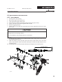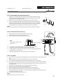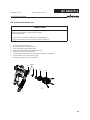
1
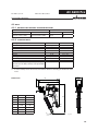
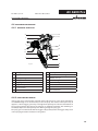
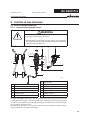
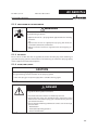
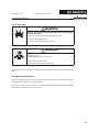
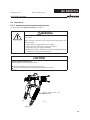
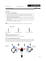
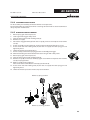
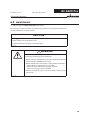
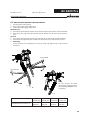
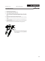
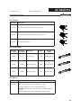
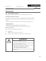
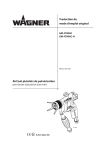
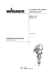
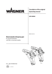
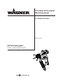
Translation of the original Operating manual AC 4600 Professional Edition 06/2012 AirCoat spray guns for flat - and round jet nozzles B_02695 II 2G X (Atex 95) EDITION 06/2012 PART NO. DOC394871 AC 4600 Pro OPERATING MANUAL Contents 1 1.1 1.2 ABOUT THESE INSTRUCTIONS Languages Warnings, notes and symbols in these instructions 5 5 5 2 2.1 2.1.1 2.1.2 2.1.3 2.2 2.2.1 2.2.2 2.2.3 2.2.4 2.2.5 2.2.6 2.3 2.4 2.4.1 2.4.2 2.4.3 2.4.4 2.5 GENERAL SAFETY INSTRUCTIONS Safety instructions for the operator Electrical equipment Personnel qualifications A safe work environment Safety instructions for staff Safe handling of WAGNER spray units Earth the unit Paint hoses Cleaning Handling hazardous liquids, varnishes and paints Touching hot surfaces Correct use Use in an explosion hazard area Correct use Explosion protection identification Maximum surface temperature Safety instructions German regulations and guidelines 6 6 6 6 6 6 7 7 7 8 8 8 8 9 9 9 9 9 9 3 3.1 3.2 3.3 3.4 3.5 3.6 3+2 YEARS GUARANTEE FOR PROFESSIONAL FINISHING Scope of guarantee Guarantee period and registration Handling Exclusion of guarantee Additional regulations CE-conformity 10 10 10 10 11 11 12 4 4.1 4.1.1 4.2 4.2.1 4.2.2 4.3 4.3.1 4.3.2 4.4 4.4.1 4.4.2 DESCRIPTION Fields of application, using in accordance with the instructions Processible materials Scope of delivery Variant with nozzle ACF3000 11/40 Variant without nozzles Data Materials of the parts transporting paint Technical data Functional description Design of spray gun Functions of the gun 13 13 13 13 13 13 14 14 14 15 15 15 5 5.1 5.1.1 5.1.2 STARTING UP AND OPERATING Installation and connection Typical AirCoat spraying system Ventilation of the spray booth 16 16 16 17 3 EDITION 06/2012 PART NO. DOC394871 AC 4600 Pro OPERATING MANUAL Contents 5.1.3 5.1.4 5.1.5 5.2 5.3 5.3.1 5.3.2 5.4 5.4.1 5.4.2 5.4.3 5.4.4 5.4.5 Air supply Fluid (paint) hoses Earthing Preparation of paints Starting-up General rules for handling the spray gun Preparation for starting up Works Start-up for spraying Adjusting the spray pattern Changing the AirCoat nozzle Cleaning aircoat nozzle Eliminate nozzle clogging 17 17 18 18 19 19 20 21 21 21 22 23 23 6.0 6.1 6.2 6.3 6.4 6.4.1 6.4.2 6.4.3 6.4.4 6.5 6.6 MAINTENANCE Finishing work and cleaning Replacing the material hose or air hose Changing or cleaning filter insert Replacing parts on the valve rod Disassembling Replacement of valve rocker seals Replacing the rod seal (35) Assembly Replacing the nozzle seal Replacing the „air“ sealing ring 24 25 26 28 30 30 31 31 31 32 33 7 TROUBLE SHOOTING AND SOLUTION 34 9 9.1 9.1.1 9.1.2 9.2 9.3 9.4 9.5 9.6 9.7 ACCESSORIES Round jet nozzle cap Nozzle inserts RXX Nozzle screwed connection compl. AirCoat nozzles ACF3000 Air caps Filter insert Hoses Swivels Miscellaneous 35 35 35 35 36 38 38 38 39 39 10 10.1 10.2 SPARE PARTS How to order spare parts? Spare parts list AC4600 Professional 40 40 41 4 EDITION 06/2012 AC 4600 Pro PART NO. DOC394871 OPERATING MANUAL 1 ABOUT THESE INSTRUCTIONS This operating manual contains information on the operation, repair and maintenance of the unit. Always observe these instructions when operating the unit. This equipment can be dangerous if it is not operated in accordance with this manual. Compliance with these instructions constitutes an integral component of the warranty agreement. 1.1 LANGUAGES 4HISOPERATINGMANUALISAVAILABLEINTHEFOLLOWINGLANGUAGES ,ANGUAGE 0ART.O ,ANGUAGE 'ERMAN %NGLISH 394870 &RENCH $UTCH 394872 )TALIAN 3PANISH 394874 $ANISH 3WEDISH 394876 1.2 0ART.O 394871 394873 394875 394877 WARNINGS, NOTES AND SYMBOLS IN THESE INSTRUCTIONS Warning instructions in this manual point out particular dangers to users and equipment and state measures for avoiding the hazard. These warning instructions fall into the following categories: DANGER Danger - imminent danger. Non-observance will result in death or serious. This line warns of the hazard! Possible consequences of failing to observe the warning instructions. The signal word points out the hazard level. SIHI_0100_GB WARNING Warning - possible danger. Non-observance can result in death or serious injury. This line warns of the hazard! Possible consequences of failing to observe the warning instructions. The signal word points out the hazard level. SIHI_0103_GB Caution - a possibly hazardous situation. Non-observance can result in minor injury. The measures for preventing the hazard and its consequences. CAUTION This line warns of the hazard! Possible consequences of failing to observe the warning instructions. The signal word points out the hazard level. SIHI_0101_GB Notice - a possibly hazardous situation. Non-observance can cause material damage. The measures for preventing the hazard and its consequences. The measures for preventing the hazard and its consequences. SIHI_0102_GB NOTICE This line warns of the hazard! Possible consequences of failing to observe the warning instructions. The signal word points out the hazard level. ➞ The measures for preventing the hazard and its consequences. Note - provide information on particular characteristics and how to proceed. 5 EDITION 06/2012 PART NO. DOC394871 AC 4600 Pro OPERATING MANUAL 2 GENERAL SAFETY INSTRUCTIONS 2.1 SAFETY INSTRUCTIONS FOR THE OPERATOR Keep these operating instructions to hand near the unit at all times. Always follow local regulations concerning occupational safety and accident prevention. 2.1.1 ELECTRICAL EQUIPMENT Electrical plant and unit To be provided in accordance with the local safety requirements with regard to the operating mode and ambient influences. May only be maintained by skilled electricians or under their supervision. Must be operated in accordance with the safety regulations and electrotechnical regulations. Must be repaired immediately in the event of problems. Must be put out of operation if they pose a hazard. Must be de-energized before work is commenced on active parts. Inform staff about planned work, observe electrical safety regulations. 2.1.2 PERSONNEL QUALIFICATIONS %NSURETHATTHEUNITISOPERATEDANDREPAIREDONLYBYTRAINEDPERSONS 2.1.3 A SAFE WORK ENVIRONMENT Make sure that the floor in the area where you are working is derivable in accordance with EN 61340-4-1. Ensure that all persons within the working area wear derivable shoes. Ensure that during spraying, persons wear derivable gloves so that they are earthed via the handle of the spray gun. Customer to provide paint mist extraction units conforming to local regulations. Ensure that the following components of a safe working environment are available: – Material/air hoses adapted to the working pressure – Personal safety equipment (breathing and skin protection) Ensure that there are no ignition sources such as naked flame, glowing wires or hot surfaces in the vicinity. Do not smoke. 2.2 SAFETY INSTRUCTIONS FOR STAFF Always follow the information in these instructions, particularly the general safety instructions and the warning instructions. Always follow local regulations concerning occupational safety and accident prevention. 6 EDITION 06/2012 PART NO. DOC394871 AC 4600 Pro OPERATING MANUAL 2.2.1 SAFE HANDLING OF WAGNER SPRAY UNITS The spray jet is under pressure and can cause dangerous injuries. Avoid injection of paint or cleaning agents: Never point the spray gun at people. Never reach into the spray jet. Before all work on the unit, in the event of work interruptions and functional faults: – Switch off the energy/compressed air supply. – Secure the spray gun against actuation. – Relieve the pressure from the spray gun and unit. – By functional faults: Identify and correct the problem, proceed as described in chapter „Trouble shooting“. In the event of skin injuries caused by paint or cleaning agents: Note down the paint or cleaning agent that you have been using. Consult a doctor immediately. Avoid danger of injury through recoil forces: Ensure that you have a firm footing when operating the spray gun. Only hold the spray gun briefly in any one position. 2.2.2 EARTH THE UNIT Depending on the electrostatic charge and the flow speed of the spray, an electrostatic charge may occur in the equipment. This could cause a spark or flame on discharging. Ensure that the unit is earthed for every spraying operation. Earth the work pieces being painted. Ensure that all persons inside the working area are earthed, e.g. that they are wearing derivable shoes. When spraying, wear derivable gloves to earth yourself via the spray gun handle. 2.2.3 PAINT HOSES Ensure that the hose material is chemically resistant to the sprayed materials. Ensure that the material hose is suitable for the pressure generated in the unit. Ensure that the following information is visible on the high pressure hose: – Manufacturer – Permissible operating overpressure – Date of manufacture. The electrical resistance of the complete high pressure hose must be less than 1 MOhm. 7 EDITION 06/2012 PART NO. DOC394871 AC 4600 Pro OPERATING MANUAL 2.2.4 CLEANING De-energize the unit electrically. Disconnect the pneumatic supply line. Relieve the pressure from the unit. Ensure that the flash point of the cleaning agent is at least 5 K above the ambient temperature. To clean, use only solvent-free cloths and brushes. Never use hard objects or spray on cleaning agents with a gun. An explosive gas/air mixture forms in closed containers. When cleaning units with solvents, never spray into a closed container. Earth the container. 2.2.5 HANDLING HAZARDOUS LIQUIDS, VARNISHES AND PAINTS When preparing or working with paint and when cleaning the unit, follow the working instructions of the manufacturer of the paints, solvents and cleaning agents being used. Take the specified protective measures, in particular wear safety goggles, protective clothing and gloves, as well as hand protection cream if necessary. Use a mask or breathing apparatus if necessary. For sufficient health and environmental safety: Operate the unit in a spray booth or on a spraying wall with the ventilation (extraction) switched on. Wear suitable protective clothing when working with hot materials. 2.2.6 TOUCHING HOT SURFACES ➞ Touch hot surfaces only if you are wearing protective gloves. ➞ When operating the unit with a coating material with a temperature of > 43 °C; 109.4 °F: - Identify the unit with a warning label that says „Warning - hot surface“. Order No. 9998910 Information label 9998911 Safety label 2.3 CORRECT USE 7!'.%2ACCEPTSNOLIABILITYFORANYDAMAGEARISINGFROMINCORRECTUSE 5SETHEUNITONLYTOWORKWITHTHEMATERIALSRECOMMENDEDBY7!'.%2 /PERATETHEUNITONLYASANENTIREUNIT $ONOTDEACTIVATESAFETYEQUIPMENT 5SEONLY7!'.%2ORIGINALSPAREPARTSANDACCESSORIES 8 EDITION 06/2012 PART NO. DOC394871 AC 4600 Pro OPERATING MANUAL 2.4 USE IN AN EXPLOSION HAZARD AREA 2.4.1 CORRECT USE 4HEUNITISSUITABLEFORWORKINGLIQUIDMATERIALSINACCORDANCEWITHTHECLASSIlCATIONINTO EXPLOSIONCLASSES 2.4.2 EXPLOSION PROTECTION IDENTIFICATION As defined in the Directive 94/9/CE (ATEX 95), the unit is suitable for use in areas where there is an explosion hazard. II 2G X CE: Ex: II: 2: G: X: Communautés Européennes Symbol for explosion protection Unit class II Category 2 (Zone 1) Ex-atmosphere gas See: "Special Notes" in the operating manual 2.4.3 MAXIMUM SURFACE TEMPERATURE X: The maximum surface temperature corresponds to the permissible material temperature. This and the permissible ambient temperature can be found in the Technical Data. 2.4.4 SAFETY INSTRUCTIONS 3AFEHANDLINGOF7!'.%2SPRAYUNITS -ECHANICALSPARKSCANFORMIFTHEUNITCOMESINTOCONTACTWITHMETAL )NANEXPLOSIVEATMOSPHERE $ONOTKNOCKORPUSHTHEUNITAGAINSTSTEELORRUSTYIRON $ONOTDROPTHESPRAYGUN 5SEONLYTOOLSTHATAREMADEOFAPERMITTEDMATERIAL )GNITIONTEMPERATUREOFTHECOATINGMATERIAL %NSURETHATTHEIGNITIONTEMPERATUREOFTHECOATINGMATERIALISABOVETHEMAXIMUM SURFACETEMPERATURE -EDIUMSUPPORTINGATOMIZING 4OATOMIZETHEMATERIALUSEONLYWEAKLYOXIDIZINGGASESEGAIR #LEANING )F THERE ARE DEPOSITS ON THE SURFACES THE UNIT MAY FORM ELECTROSTATIC CHARGES &LAMES OR SPARKSCANFORMIFTHEREISADISCHARGE 2EMOVEDEPOSITSFROMTHESURFACESTOMAINTAINCONDUCTIVITY 2.5 GERMAN REGULATIONS AND GUIDELINES See chapter 3.3 9 EDITION 06/2012 PART NO. DOC394871 AC 4600 Pro OPERATING MANUAL 3 3+2 YEARS GUARANTEE FOR PROFESSIONAL FINISHING 3.1 SCOPE OF GUARANTEE All Wagner professional colour application devices (hereafter referred to as products) are carefully inspected, tested and are subject to strict checks under Wagner quality assurance. Wagner exclusively issues extended guarantees to commercial or professional users (hereafter referred to as „customer“) who have purchased the product in an authorised specialist shop, and which relate to the products listed for that customer on the Internet under www.wagner-group.com/profi-guarantee. The buyer‘s claim for liability for defects from the purchase agreement with the seller as well as statutory rights are not impaired by this guarantee. We provide a guarantee in that we decide whether to replace or repair the product or individual parts, or take the device back and reimburse the purchase price. The costs for materials and working hours are our responsibility. Replaced products or parts become our property. 3.2 GUARANTEE PERIOD AND REGISTRATION The guarantee period amounts to 36 months. For industrial use or equal wear, such as shift operations in particular, or in the event of rentals it amounts to 12 months. Systems driven by petrol or air are also guaranteed for a 12 month period. The guarantee period begins with the day of delivery by the authorised specialist shop. The date on the original purchase document is authoritative. For all products bought in authorised specialist shops from 01.02.2009 the guarantee period is extended to 24 months providing the buyer of these devices registers in accordance with the following conditions within 4 weeks of the day of delivery by the authorised specialist shop. Registration can be completed on the Internet under www.wagner-group.com/profi-guarantee. The guarantee certificate is valid as confirmation, as is the original purchase document that carries the date of the purchase. Registration is only possible if the buyer is in agreement with having the data being stored that is entered during registration. When services are carried out under guarantee the guarantee period for the product is neither extended nor renewed. Once the guarantee period has expired, claims made against the guarantee or from the guarantee can no longer be enforced. 3.3 HANDLING If defects can be seen in the materials, processing or performance of the device during the guarantee period, guarantee claims must be made immediately, or at the latest within a period of 2 weeks. The authorised specialist shop that delivered the device is entitled to accept guarantee claims. Guarantee claims may also be made to the service centres named in our operating instructions. The product has to be sent without charge or presented together with the original purchase document that includes details of the purchase date and the name of the product. In order to claim for an extension to the guarantee, the guarantee certificate must be included. The costs as well as the risk of loss or damage to the product in transit or by the centre that accepts the guarantee claims or who delivers the repaired product, are the responsibility of the customer. 10 EDITION 06/2012 PART NO. DOC394871 AC 4600 Pro OPERATING MANUAL 3.4 EXCLUSION OF GUARANTEE Guarantee claims cannot be considered - for parts that are subject to wear and tear due to use or other natural wear and tear, as well as defects in the product that are a result of natural wear and tear, or wear and tear due to use. This includes in particular cables, valves, packaging, jets, cylinders, pistons, means-carrying housing components, filters, pipes, seals, rotors, stators, etc. Damage due to wear and tear that is caused in particular by sanded coating materials, such as dispersions, plaster, putty, adhesives, glazes, quartz foundation. - in the event of errors in devices that are due to non-compliance with the operating instructions, unsuitable or unprofessional use, incorrect assembly and/or commissioning by the buyer or by a third party, or utilisation other than is intended, abnormal ambient conditions, unsuitable coating materials, unsuitable operating conditions, operation with the incorrect mains voltage supply/frequency, over-operation or defective servicing or care and/or cleaning. - for errors in the device that have been caused by using accessory parts, additional components or spare parts that are not original Wagner parts. - for products to which modifications or additions have been carried out. - for products where the serial number has been removed or is illegible - for products to which attempts at repairs have been carried out by unauthorised persons. - for products with slight deviations from the target properties, which are negligible with regard to the value and usability of the device. - for products that have been partially or fully taken apart. 3.5 ADDITIONAL REGULATIONS The above guarantees apply exclusively to products that have been bought by authorised specialist shops in the EU, CIS, Australia and are used within the reference country. If the check shows that the case is not a guarantee case, repairs are carried out at the expense of the buyer. The above regulations manage the legal relationship to us concludingly. Additional claims, in particular for damages and losses of any type, which occur as a result of the product or its use, are excluded from the product liability act except with regard to the area of application. Claims for liability for defects to the specialist trader remain unaffected. German law applies to this guarantee. The contractual language is German. In the event that the meaning of the German and a foreign text of this guarantee deviate from one another, the meaning of the German text has priority. J. Wagner GmbH Division Professional Finishing Otto Lilienthal Strasse 18 88677 Markdorf Federal Republic of Germany Wagner professional guarantee (Status 01.02.2009) 11 EDITION 06/2012 PART NO. DOC394871 AC 4600 Pro OPERATING MANUAL 3.6 CE-CONFORMITY Herewith we declare that the supplied version of AC 4600 Pro (blue) AC 4600 Pro (green) AC 4600 Pro (red) GM 4600 Pro Box Complies with the following guidelines: 98/37/EG 94/9/EG Applied standards, in particular: DIN EN ISO 12100-1, 2004-04 DIN EN ISO 14121,2007-12 DIN EN ISO 12100-2, 2004-04 DIN EN ISO 3746, 1995-12 DIN EN 1127-1, 2008-02 DIN EN 13463-1, 2002-04 DIN EN 1953, 1998-12 DIN EN ISO 13732-1, 2006-12 Applied national technical standards and specifications, in particular: a) b) c) d) e) BGR 500 BGR 500 BGR 104 TRBS 2153 BGR 180 f ) BGI 740 g) ZH 1/406 Part 2, Chap. 2.29„Using coating materials“ Part 2, Chap. 2.36„Working with liquid ejection devices“ Explosion protection rules Avoiding ignition risks Setting up for cleaning with solvents for cleaning workpieces with solvents Painting rooms and equipment Guidelines for liquid ejection devices Note: All titles can be ordered from Heymanns Publishing House in Cologne, or they are to be found in the Internet. txt 00141 GB CE Certificate of Conformity The certificate is enclosed with this product. The certificate of conformity can be reordered from your WAGNER representative, quoting the product and serial number. Part number: 398892 12 EDITION 06/2012 PART NO. DOC394871 AC 4600 Pro OPERATING MANUAL 4 DESCRIPTION 4.1 FIELDS OF APPLICATION, USING IN ACCORDANCE WITH THE INSTRUCTIONS The gun is suitable for atomising liquid materials, particularly coating materials, using the AirCoat process. 4.1.1 PROCESSIBLE MATERIALS Top-coat paints, primer paints, corrosion protection solvents, textured paints, lyes, staining solvents, clear paints, parting solvents, etc. on a solvent or water basis. If you want to spray other working materials than the aforementioned, turn please to a Wagner agency. WARNING Hot coating substances! Burns Wear antistatic protective gloves. When operating the unit with a coating material with a temperature greater than 43 °C; 109.4 °F: Identify the unit with a warning sticker "Warning - hot surface". SIHI_0019_GB Note: Please contact your local WAGNER dealer and the paint manufacturer if you encounter application problems. 4.2 SCOPE OF DELIVERY These AirCoat gun is available with three different variants. 4.2.1 VARIANT WITH NOZZLE ACF3000 11/40 Qty Part No. Description 1 394150 AC 4600 Professional (blue) 1 394151 AC 4600 Professional (red) 1 394152 AC 4600 Professional (green) 4.2.2 VARIANT WITHOUT NOZZLES Qty Part No. Description 1 394156 AC 4600 Professional (blue) 1 394157 AC 4600 Professional (red) 1 394158 AC 4600 Professional (green) The standard equipment for each variant includes: Qty Part No. Description 1 398892 CE-conformity 1 394870 Operating manual German 1 see chap. 1 Operating manual for the other language For special versions the delivery note applies. 13 EDITION 06/2012 AC 4600 Pro PART NO. DOC394871 OPERATING MANUAL 4.3 DATA 4.3.1 MATERIALS OF THE PARTS TRANSPORTING PAINT Metal Plastic Tungsten carbide Stainless steel 1.4305 POM FPM Stainless steel 1.4301 Stainless steel 1.4104 PTFE PA 4.3.2 TECHNICAL DATA Description Maxi. air inlet pressure Maxi. material pressure Paint connection Air connection Filter insert ** Weight pH range of the material Maxi. temperature material Maxi. temperature air Units MPa/ psi/ bar MPa/ psi/ bar Inch Inch Mesh g/ oz pH °C/ °F °C/ °F dB(A) Sound level at 0.3 MPa; 3 bar; 43.5 psi air pressure and 11 MPa; 110 bar; 1549 psi material pressure*** Value 0.8/ 120/ 8 25/ 3625/ 250 NPSM1/4 G1/4“ 100 671 / 23.7 3.5 - 9 55/ 131 43/ 109 < 82 ** Other filter types see chapter 9.4 *** A rated sound pressure level measured at 0.5m distance according to DIN EN ISO 3746 -1995. C E A Dimensions Dim. mm inch A 181 7.13 B 248 9.76 C 48 1.88 D 160 6.30 E 38.5 1.52 F - NPSM1/4“ G - G1/4“ B D G F B_02696 14 EDITION 06/2012 AC 4600 Pro PART NO. DOC394871 OPERATING MANUAL 4.4 FUNCTIONAL DESCRIPTION 4.4.1 DESIGN OF SPRAY GUN B C A J I E D H K M L F N G B_02697 Description Description A Suspension hook H Union nut with nozzle guard B Shaping air regulator I Nozzle / Air cap C Spring cover J Gun housing D Trigger guard K Filter housing E Trigger safety L Handle tube F Air connection M Swivel Air G Paint connection N 4.4.2 Swivel Material FUNCTIONS OF THE GUN If the trigger (D) is operated with released locking (E), first the air valve opens. Atomizing air to flow through via air connection (F) to the air cap (I). The material valve opens only if approx. 1/2 of the trigger guard way are bridged. The quantity of air for the atomization of the jet spray becomes preset over the external air automatic controller. The atomizing air control (B) adjusts the total quantity of air flowing trough the spray gun. The spray gun is rendered safe with the trigger safety catch (E). Turn the trigger safety catch in the spraying direction and fasten in the groove. 15 EDITION 06/2012 AC 4600 Pro PART NO. DOC394871 OPERATING MANUAL 5 STARTING UP AND OPERATING 5.1 INSTALLATION AND CONNECTION 5.1.1 TYPICAL AIRCOAT SPRAYING SYSTEM WARNING Incorrect installation/operation! Risk of injury and damage to equipment When putting into operation and for all work, read and follow the operating instructions and safety regulations for the additionally required system components. SIHI_0050_GB E D G F M Profe ssion al C B I K H A J L B_02673 G AirCoat Gun A Paint-pump H High-pressure fluid hose B Pressure air shut off valve I High pressure filters/ Relief valve C Pressure regulator J Return D Air pressure regulator with filter K Stand trolley E Earthing cable L Suction system Air hose, el. conductive M Compressed air main F The pray gun 4600AC Professional must be used a part of a spraying system. The spraying system shown in the figure is only one example of an electrostatic Aircoat spraying system. It is not an actual system design. Contact your Wagner distributor for assistance in designing a system to meet your needs. The operating instructions and the safety regulations for the additional system components used must be read before starting-up. 16 EDITION 06/2012 PART NO. DOC394871 AC 4600 Pro OPERATING MANUAL 5.1.2 VENTILATION OF THE SPRAY BOOTH WARNING Toxic and/or flammable vapor mixtures! Risk of poisoning and burns Operate the unit in a spraying booth approved for the working materials. -or Operate the unit on an appropriate spraying wall with the ventilation (extraction) switched on. Observe national and local regulations for the outgoing air speed. SIHI_0028_GB 5.1.3 AIR SUPPLY The use of an air filter with the air regulator (D) ensures that only dry, clean atomising air gets into the spray gun! Dirt and moisture in the atomising air reduce the spraying quality and the appearance of the finished piece. 5.1.4 FLUID (PAINT) HOSES CAUTION Impurities in the spraying system! Spray gun blockage, materials harden in the spraying system Flush the spray gun and paint supply with a suitable cleaning agent. SIHI_0001_GB DANGER Bursting hose, bursting threaded joints! Danger to life from injection of material Ensure that the hose material is chemically resistant. Ensure that the spray gun, threaded joints and material hose between the unit and the spray gun is suitable for the pressure generated in the unit. Ensure that the following information can be seen on the high pressure hose: - Manufacturer - Permissible operating pressure - Date of manufacture. SIHI_0029_GB 17 EDITION 06/2012 PART NO. DOC394871 AC 4600 Pro OPERATING MANUAL 5.1.5 EARTHING WARNING Discharge of electrostatically charged components in atmospheres containing solvents! Explosion hazard from electrostatic sparks or flames Earth all unit components. Earth the workpieces being painted. SIHI_0027_GB WARNING Heavy paint mist if earthing is insufficient! Risk of poisoning Insufficient paint application quality Earth all unit components. Earth the workpieces being painted. SIHI_0003_GB Any material containers and the unit must be connected by a potential equalisation (earth) cable. 5.2 PREPARATION OF PAINTS The viscosity of the paints is of great importance. The best results are obtained with paints between 80 and 260 milli Pascal x Sec (mPas). Please also read the technical data sheet for the paint for optimal processing, viscosity adjustment and intermixing of the material. 18 EDITION 06/2012 PART NO. DOC394871 AC 4600 Pro OPERATING MANUAL 5.3 STARTING-UP 5.3.1 GENERAL RULES FOR HANDLING THE SPRAY GUN ➞ Observe general safety instructions in chapter 2. WARNING Unintentional putting into operation! Risk of injury Before all work on the unit, in the event of work interruptions and functional faults: Switch off the energy/compressed air supply. Relieve the pressure from the spray gun and unit. Secure the spray gun against actuation. By functional faults: Identify and correct the problem, proceed as described in chap „Trouble shooting“. SIHI_0065_GB CAUTION Cleaning agent in the air duct! Functional faults caused by swollen seals Always point the spray gun down when cleaning. Ensure that neither paint nor cleaning agent enters the air duct. SIHI_0005_GB Trigger safety catch in on (safe) position Air B_02700 Material 19 EDITION 06/2012 PART NO. DOC394871 AC 4600 Pro OPERATING MANUAL 5.3.2 PREPARATION FOR STARTING UP 1. 2. 3. 4. 5. Secure the spray gun. Connect material hose to the spray gun and material supply system. Connect air hose to spray gun and to oil-free, dry air supply with regulator. Insert suitable gun filter. Place the nozzle into the nozzle seal. Fit the air cap over the nozzle, ensuring that the location flats (X) are in line. Fit the union nut with nozzle guard and tighten by hand. 6. Visually check the permissible pressures for all the system components. 7. Make sure that the unit and all other conductive parts within the work area are earthed. 8. Set material pressure at 100 bar; 10 MPa; 1450 psi and use a suitable medium (solvent or water) to check that connections do not leak. x B_02261 Note: Pull the trigger and then release, checking that the gun closes cleany. 9. Relieve spray gun and unit pressure and secure the spray gun. WARNING Operating the gun with a coating material with a temperature higher than 43°C; 109.4°F Burns from hot surface (to 60°C; 140°F) Wear antistatic protective gloves: Identify the spray gun with a warning label that says „Warning - hot surface“( Part No. 9998910 or 9998911). SIHI_0135_GB 20 EDITION 06/2012 PART NO. DOC394871 AC 4600 Pro OPERATING MANUAL 5.4 WORKS 5.4.1 START-UP FOR SPRAYING 1. Start up with material supply set to approx. 8 MPa; 80 bar; 1160 psi operating pressure 2. Spray (release trigger safety catch and pull trigger) and check the atomisation. 3. Set the fluid pressure to the point where a further increase in fluid pressure would significantly improve fluid atomization. 4. Open air pressure controller for the atomizer air and adjust so as to achieve optimal atomization. (The interrelation between spray pattern and atomizer air is shown in the figure below). 5. Use the shaping air controller on the gun to adjust the shaping air to atomizer air ratio, until the optimal spray pattern is achieved. Note: Repeat point 4 and 5 until the optimum spray pattern is reached (process iterative). Spray pattern B_00071 No atomizing air Too little atomizing air Correct amount of air Note The paint output volume can be changed by: Changing the material pressure or Fitting another flat jet nozzle (see chap. 5.4.3 and chap. 9). • • 5.4.2 ADJUSTING THE SPRAY PATTERN The spray pattern can be adjusted to suit the object being sprayed using the fan air regulator. The illustration below shows the influence of the shaping air regulator on the spraying pattern. Other nozzle sizes can be used to obtain larger or smaller spraying patterns. Shaping air fully open Shaping air fully closed B_02262 21 EDITION 06/2012 AC 4600 Pro PART NO. DOC394871 OPERATING MANUAL 5.4.3 CHANGING THE AIRCOAT NOZZLE CAUTION Defective AirCoat nozzle! Insufficient paint application quality Do not use sharp-edged objects to treat hard metal on the AirCoat nozzle. SIHI_0020_GB 1. 2. 3. 4. 5. Relieve spray gun and unit pressure. Secure gun with trigger safety catch. Screw off the union nut (A). Remove air cap (B). Press AirCoat nozzle (C) out of the air cap (B) by hand and brush with cleaning solvent until all remaining paint has been dissolved. 6. Mounting: Place AirCoat nozzle (C) in nozzle seal (D). 7. Fit the aircap (B) over the nozzle (C), ensuring that the location flats (X) are in line. 8. Fit the union nut with nozzle guard (A) and tighten by hand. x B_02261 D B C A B_02701 22 EDITION 06/2012 AC 4600 Pro PART NO. DOC394871 OPERATING MANUAL 5.4.4 CLEANING AIRCOAT NOZZLE For disassembly and assembly of AirCoat nozzles see chapter 5.4.3. The AirCoat nozzle (C) can be placed into a cleaning solvent which has been recommended by the paint manufacturer. 5.4.5 1. 2. 3. 4. 5. 6. 7. 8. 9. 10. 11. 12. 13. 14. 15. 16. ELIMINATE NOZZLE CLOGGING Relieve spray gun and unit pressure. Secure gun with trigger safety catch. Unscrew the union nut with nozzle guard (A). Remove air cap (B). Pull out the clogged nozzle (C) from the air cap (B), reverse it and replace it into nozzle seal (D). Fit the aircap (B) over the nozzle (C), ensuring that the location flats (X) are in line. Fit the union nut with nozzle guard (A) over the air cap (B) onto the spray gun and tighten by hand. Switch the material pressure back on. Turn the safety catch to the spraying position and briefly pull trigger. When the blockage has been flushed out secure the gun with safety catch. Relieve spray gun and unit pressure. Unscrew the union nut with nozzle guard (A). Remove air cap (B) and reverse nozzle (C) again. Clean nozzle and replace on the nozzle seal (D) in spray position. Refit air cap (B) on the nozzle (C). Take care that the nozzle fitted is correctly (see flat side X). Fit the union nut with nozzle guard (A) over the air cap (B) onto the spray gun and tighten by hand. Switch the material pressure and the air pressure back on. x B_02261 Nozzle in „spray“ position D C B A Nozzle in „cleaning“ position B_02702 23 EDITION 06/2012 PART NO. DOC394871 AC 4600 Pro OPERATING MANUAL 6.0 MAINTENANCE ➞ Observe general safety instructions in chapter 2. The spray gun and the unit must be cleaned every day. The cleaning solvent used for this must be suitable for the spray material. CAUTION Cleaning agent in the air duct! Functional faults caused by swollen seals Never immerse the spray gun in cleaning agent. SIHI_0066_GB WARNING Incorrect maintenance/repair! Risk of injury and damage to the equipment Repairs and part replacement may only be carried out by specially trained staff or a WAGNER service center. Before all work on the unit and in the event of work interruptions: - Switch off the energy/compressed air supply. - Relieve the pressure from the spray gun and unit. - Secure the spray gun against actuation. Observe the operating and service instructions when carrying out all work. SIHI_0004_GB 24 EDITION 06/2012 PART NO. DOC394871 AC 4600 Pro OPERATING MANUAL 6.1 FINISHING WORK AND CLEANING DANGER Exploding gas/ air mixture! Danger to life from flying parts and burns Never spray into a closed container. Earth the container. SIHI_0008_GB CAUTION Cleaning agent in the air duct! Functional faults caused by swollen seals Always point the spray gun down when cleaning. Ensure that neither paint nor cleaning agent enters the air duct. SIHI_0005_GB WARNING Explosive atmosphere! Explosive gases are produced when aluminium comes into contact with halogenized hydrocarbons To clean aluminium, do not use liquids containing halogenized hydrocarbons. SIHI_0009_GB Note: Methylene chloride is not recommended as a flushing or cleaning solvent with this gun or any system components. 1. 2. 3. 4. 5. Relieve spray gun and unit pressure. Secure gun with trigger safety catch. Connect cleaning supply. Remove AirCoat -jet nozzle and clean separately (see chapter 5.4.3). Pressurize the cleaning supply to approx. 4 MPa; 40 bar; 580 psi and thoroughly flush the spray gun. 6. Relieve spray gun and unit pressure. 7. Secure gun with trigger safety catch. 8. Clean gun body with a cleaning agent recommended by the manufacturer, and dry with a cloth. 25 EDITION 06/2012 AC 4600 Pro PART NO. DOC394871 OPERATING MANUAL 6.2 REPLACING THE MATERIAL HOSE OR AIR HOSE 1. Finishing work and cleaning. 2. Relieve spray gun and unit pressure. 3. Secure gun with trigger safety catch. Material hose 4. Place open-ended wrench wrench size A on flats of paint connection and counterhold. 5. Turn nut to the right with open-ended wrench wrench size B and unscrew material hose. Air hose 4. Place open-ended wrench wrench size D on flats of air connection and counterhold. 5. Turn nut to the right with open-ended wrench wrench size C and unscrew air hose. 6. Mounting: Fit the material hose respectively air hose by hand and tighten with 2 open-ended wrenches. Counterhold D C Counterhold A Note: Do not unscrew the filter housing. The nut must only be unscrewed by WAGNER- Service-Agency. B B_02703 B_02704 Description AC 4600 Professional NPS 1/4“ Key A Key B Key C Key D wrench size wrench size wrench size wrench size 17 mm 0.67 inch 19 mm 0.75 inch 17 mm 0.67 inch 14 mm 0.55 inch 26 EDITION 06/2012 AUSGABE 01/2008 BESTELLNUMMER PART NO. DOC394871 DOC394870 AC 4600 Pro OPERATING MANUAL BETRIEBSANLEITUNG 27 EDITION 06/2012 PART NO. DOC394871 AC 4600 Pro OPERATING MANUAL 6.3 CHANGING OR CLEANING FILTER INSERT Close Loosen Counterhold D Loosen E Description B A AC 4600 Professional NPS 1/4“ Key D Key E wrench size wrench size 13 mm 0.51 inch 17 mm 0.67 inch X C "? B_02705 28 EDITION 06/2012 PART NO. DOC394871 AC 4600 Pro OPERATING MANUAL 1. 2. 3. 4. 5. 6. 7. 8. Finishing work and cleaning. Relieve spray gun and unit pressure. Secure gun with trigger safety catch. Losen complete swivel by hand through turning at the handle tube (C) and drive out downward together with the material hose. Pull filter insert (A) out of the filter housing (B). Flush swivel, filter housing and filter insert (A) with cleaning agent. Push in cleaned or new filter insert (A) with cone (X) upward into the filter housing. Put handle tube with female hexagon on swivel and screw from down over the filter insert onto the filter housing by hand. Note: Do not unscrew the filter housing. The nut must only be unscrewed by WAGNER - Service-Agency. B_02704 29 EDITION 06/2012 AC 4600 Pro PART NO. DOC394871 OPERATING MANUAL 6.4 REPLACING PARTS ON THE VALVE ROD 6.4.1 1. 2. 3. 4. 5. 6. 7. DISASSEMBLING Finishing work and cleaning. Relieve spray gun and unit pressure. Secure gun with trigger safety catch. Unscrew spring cover (5) and remove compression springs (2) and (3). Loosen screw (22) and remove together with nut (20). Remove trigger guard (21). Loosen sealing screw (10) with single open-end wrench (100) with wrench size 7 mm; 0.28 inches. CAUTION Unsuitable tool! Damage to seals and sealing surfaces Do not hold the valve rod with pliers or a similar tool. SIHI_0006_GB 8. Carefully pull the complete valve rod (B) together with sealing screw out of the gun housing (A) toward the rear. 9. Hold the clamping sleeve (4) with open-end wrench (101) wrench size 6 mm; 0.24 inches and loosen the collet chuck (18) with open-end wrench (102) wrench size 5 mm; 0.20 inches. 10. Carefully pull the valve rod (34) out toward the front. Replace the relevant parts. 87.9 mm ±0.15 B 5 2 102 101 A 3 5 Nm ±1 3.69 lbft 20 100 21 4 85 18 22 19 10 12 11 34 50 51 52 83 53 B_02706 30 EDITION 06/2012 AC 4600 Pro PART NO. DOC394871 OPERATING MANUAL 6.4.2 REPLACEMENT OF VALVE ROCKER SEALS 1. Support valve tappet (50) with single open-end wrench with wrench size 13 mm; 0.51 inches and unscrew cover (53) with single open-end wrench with wrench size 7 mm; 0.28 inches. 2. Remove air valve seal (51) and seal (52) and replace with new seals. 3. Screw valve tappet (50) and cover (53) together by hand. Carefully tighten in small increments with open-end wrench with wrench size 7 mm; 0.28 inches and with wrench size 13 mm; 0.51 inches until a slight resistance is perceptible when moving the valve rod (34) in the valve tappet. Note: The seal (52) can be pulled out of the cover (53) with the help of an eyebolt. 6.4.3 50 51 52 53 B_02274 REPLACING THE ROD SEAL (35) 1. Carefully pull the rod seal (35) out of the gun housing. 2. Clean sealing surfaces in the gun housing. 3. Mount new rod seal (35) to the rod seal tool (84). 22 Note Installation position of the rod seal (35) 84 Spraying direction 35 21 B_02688 4. Insert rod seal tool (84) together with rod seal (35) into the hole. 5. Fit trigger guard (21) with screw (22) to body of gun and 6. Carefully push the tool with the rod seal (35) over the trigger guard (21) into the recess in the housing. 7. Remove trigger guard (21), screw (22) and rod seal tool (84). 6.4.4 B_02268 ASSEMBLY 1. Fit seal collar (11) to valve rod (14), together with inserted O-ring (12) and sealing screw (10). 2. Push completely assembled valve tappet (19) onto valve rod (14). 3. Insert preassembled valve rod into the collet chuck (18) as far as the stop. 4. Fix clamping sleeve (4) with wrench size 6 mm; 0.24 inches, screw the preassembled valve rod to the clamping sleeve and tighten (open-end wrench with wrench size 5 mm; 0.20 inches). 5. Carefully insert the complete valve rod (B) into the gun housing. 6. Screw in sealing screw (10) but do not tighten yet. 7. Position trigger guard (21) and secure with screw (22) and nut (20). 8. Insert compression springs (3) and (2) and screw on the spring cover (5). 9. Carefully tighten the seal collar (11, 12) by turning the sealing screw (10). Ensure that the trigger guard moves easily. 10. Start up in accordance with chapter 5.3. Note: Only use silicone and resin free grease. 31 EDITION 06/2012 PART NO. DOC394871 AC 4600 Pro OPERATING MANUAL 6.5 REPLACING THE NOZZLE SEAL CAUTION Defective nozzle seal! Material sprays into the air cap next to the nozzle Risk of contamination Do not clean the nozzle seal with sharp-edged objects. Replace the nozzle seal if the sealing surface is damaged. SIHI_0021_GB 1. 2. 3. 4. 5. 6. 7. 8. Finishing work and cleaning. Relieve spray gun and unit pressure. Secure gun with trigger safety catch. Unscrew the union nut with nozzle guard (33). Remove air cap (36) and nozzle (13). Carefully release the nozzle seal (17) with the help of a screwdriver. Fit new nozzle seal to valve housing (16). Continue assembly in the reverse order. 14 (F) 16 17 13 36 33 B_02707 32 EDITION 06/2012 AC 4600 Pro PART NO. DOC394871 OPERATING MANUAL 6.6 REPLACING THE „AIR“ SEALING RING CAUTION Forming air and atomizer air not separate! Poor spray pattern Spray jet cannot be adjusted Treat the distributor seal (F) with care. SIHI_0030_GB 1. 2. 3. 4. 5. 6. 7. 8. 9. 10. Finishing work and cleaning. Relieve spray gun and unit pressure. Secure gun with trigger safety catch. Unscrew the union nut with nozzle guard (33). Remove air cap (36) and nozzle (13). Remove defective sealing ring (14/F) with the help of pipe tongs or with a large screwdriver. Mounting: Fit new distributor seal (14/F) to air cap (36). Place air cap in body of gun together with sealing ring (14). Attach union nut (33) and screw in until the sealing ring snaps into place in the mounting groove (snap hearable). Demount union nut (33) and air cap (36) and complete spray gun according to paragraph 5.4.3. 13 / 2 36 33 14 (F) 0 1 B_02708 33 EDITION 06/2012 AC 4600 Pro PART NO. DOC394871 OPERATING MANUAL 7 TROUBLE SHOOTING AND SOLUTION Functional fault Cause Remedy Insufficient material discharge Nozzle too small Select larger nozzle Poor spray pattern see chapter 9 Material pressure to low Increase material pressure Filter of gun or highpressure filter at pump clogged Clean or replace filter Nozzle is clogged Nozzle cleaning Valve stem defective Replace valve rod Wrongly adjusted atomizing air Readjust atomizing air Nozzle to large Select smaller nozzle 6.3 5.4.5 6.4 5.4.1 9.1 Material pressure to low Increase pressure at pump Valve rod leaks (Paint- or air path) Spray gun will not shut-off correctly Material viscosity to high Thin material in accordance with the manufacturer‘s instructions Partial nozzle blockage Nozzle cleaning 5.4.5 Wrongly adjusted atomizing air Readjust the atomizing air 5.4.1 Aircap faulty (blocked holes, damaged seal) Clean or replace air cap Wrong aircap type Replace as required aircap (solvent / water based) Paint seal (packing) Adjust or replace packing or damaged or worn, valve replace valve stem complete stem damaged 6.4 Air valve seals damaged Replace air valve seals 6.4 Pretension to low Re tighten sealing screw Worn valve seat / valve ball Replace parts Packing-screw too tight, Replace the seals or packing stuck with dried paint 6.4 6.4 34 EDITION 06/2012 AC 4600 Pro PART NO. DOC394871 OPERATING MANUAL 9 ACCESSORIES 9.1 ROUND JET NOZZLE CAP 9.1 Part No. Description 394180 Round jet nozzle cap (without nozzle insert) 9.1.2 B_02276 9.1.1 9.1.1 NOZZLE INSERTS RXX Part No. Description Marking Volume flow* Jet-ø ** 132720 Nozzle insert R11 11 0.16; 160 approx. 250; 9.84 132721 Nozzle insert R12 12 0.22; 220 approx. 250; 9.84 132722 Nozzle insert R13 13 0.27; 270 approx. 250; 9.84 132723 Nozzle insert R14 14 0.34; 340 approx. 250; 9.84 132724 Nozzle insert R15 15 0.38; 380 approx. 250; 9.84 132725 Nozzle insert R16 16 0.43; 430 approx. 250; 9.84 132726 Nozzle insert R17 17 0.48; 480 approx. 250; 9.84 132727 Nozzle insert R18 18 0.53; 530 approx. 250; 9.84 132728 Nozzle insert R19 19 0.59; 590 approx. 250; 9.84 132729 Nozzle insert R20 20 0.65; 650 approx. 250; 9.84 132730 Nozzle insert R21 21 0.71; 710 approx. 250; 9.84 132731 Nozzle insert R22 22 0.77; 770 approx. 250; 9.84 B_02277 * Volume flow in ml/min; cc/min water at 10 MPa; 100 bar; 1450 psi. ** Jet width in mm; inches at a distance of 30 cm; 11.8 inches from the object and at a pressure of 10 MPa; 100 bar; 1450 psi, synthetic resin paint, 20 DIN4 seconds. 9.1.2 NOZZLE SCREWED CONNECTION COMPL. Part No. Description 132922 Nozzle screwed connection compl. B_02278 35 EDITION 06/2012 AC 4600 Pro PART NO. DOC394871 OPERATING MANUAL 9.2 AIRCOAT NOZZLES ACF3000 B_02280 Sprayangle 379107 07/10 0.007-0.18 100 379207 07/20 0.007-0.18 200 379209 09/20 0.009-0.23 200 0 379309 09/30 0.009-0.23 30 379409 09/40 0.009-0.23 400 379509 09/50 0.009-0.23 500 379609 09/60 0.009-0.23 600 379111 11/10 0.011-0.28 100 379211 11/20 0.011-0.28 200 379311 11/30 0.011-0.28 300 379411 11/40 0.011-0.28 400 379511 11/50 0.011-0.28 500 379611 11/60 0.011-0.28 600 379113 13/10 0.013-0.33 100 0 379213 13/20 0.013-0.33 20 379313 13/30 0.013-0.33 300 379413 13/40 0.013-0.33 400 379513 13/50 0.013-0.33 500 379613 13/60 0.013-0.33 600 379813 13/80 0.013-0.33 800 379115 15/10 0.015-0.38 100 0 379215 15/20 0.015-0.38 20 379315 15/30 0.015-0.38 300 379415 15/40 0.015-0.38 400 379515 15/50 0.015-0.38 500 379615 15/60 0.015-0.38 600 379815 15/80 0.015-0.38 800 379217 17/20 0.017-0.43 200 0 379317 17/30 0.017-0.43 30 379417 17/40 0.017-0.43 400 379517 17/50 0.017-0.43 500 379617 17/60 0.017-0.43 600 379817 17/80 0.017-0.43 800 Recommended edge filter Use Natural paint Transparent lacquer Oils Synthetic resin paints PVC paint Paints Undercoat Priming paint Filler 100 mesh Diameter of bore inch; mm 200 mesh Marking Filler Rustproofing paint Rustproofing paint Latex paint 60 mesh Part No. 36 EDITION 06/2012 AC 4600 Pro PART NO. DOC394871 OPERATING MANUAL B_02280 379219 Marking 19/20 Diameter of bore inch; mm 0.019-0.48 Sprayangle Recommended edge filter Use Rustproofing paint Latex paint 0 20 0 379319 19/30 0.019-0.48 30 379419 19/40 0.019-0.48 400 379519 19/50 0.019-0.48 500 379619 19/60 0.019-0.48 600 379819 19/80 0.019-0.48 800 379221 21/20 0.021-0.53 200 379421 21/40 0.021-0.53 400 379521 21/50 0.021-0.53 500 379621 21/60 0.021-0.53 600 379821 21/80 0.021-0.53 800 379423 23/40 0.023-0.58 400 379623 23/60 0.023-0.58 600 379823 23/80 0.023-0.58 800 379425 25/40 0.025-0.64 400 379625 25/60 0.025-0.64 600 379825 25/80 0.025-0.64 800 379427 27/40 0.027-0.69 400 379627 27/60 0.027-0.69 600 379827 27/80 0.027-0.69 800 379429 29/40 0.029-0.75 400 379629 29/60 0.029-0.75 600 379829 29/80 0.029-0.75 800 379431 31/40 0.031-0.79 400 379631 31/60 0.031-0.79 600 379831 31/80 0.031-0.79 800 379435 35/40 0.035-0.90 400 379635 35/60 0.035-0.90 600 379835 35/80 0.035-0.90 800 Mica paint Zinc dust coating Rustproofing paint Distemper 60 mesh Part No. 37 EDITION 06/2012 AC 4600 Pro PART NO. DOC394871 OPERATING MANUAL 9.3 AIR CAPS Part No. Description 394910 Air cap LV compl. (red) for low viscosity paints B_02257 394911 Air cap HV compl. (blue) for high viscosity paints B_02256 394912 Air cap compl. (green) B_02709 9.4 FILTER INSERT Part No. for 1 piece Part No. for 10 piec. 34383 97022 43235 97023 Filter type Mesh Use for nozzles Gun filter rot 200 0.007“ - 0.015“ Gun filter yellow 100 0.015“ - 0.019“ "? "? 34377 97024 Gun filter white 50 0.017“ - 0.021“ "? 9.5 HOSES Part No. Description 9984595 9984596 Hose set AC Material DN3; Air DN6 7.5 m; 24.61 ft Hose set AC Material DN3; Air DN6 10 m; 32.81 ft Consisting of Material-, Air- and protective hose. Material: NPSM1/4“; DN 3 mm; ID 0.12 inch; 27 MPa; 270 bar; 3916 psi Air: G1/4“; DN 6 mm; ID 0.24 inch; 0.8 MPa; 8 bar; 116 psi 38 EDITION 06/2012 PART NO. DOC394871 AC 4600 Pro OPERATING MANUAL 9.6 SWIVELS Part No. Description 347706 Swivel for paint connection (NPSM 1/4“) B_02712 364938 Swivel for air connection G1/4“ B_02687 9.7 MISCELLANEOUS Part No. Description 9997001 Nozzle cleaning brush 394942 Service set AC 4600 Professional 394904 Conversion kit 16 MPa; 160 bar; 2320 ps 394905 Conversion kit 25 MPa; 250 bar; 3625 psi 367560 Double connection NPSM1/4“ (outside thread) for paint hose extension 9985720 Double nipple G1/4“ (outside thread) for air hose extension B_02685 B_02686 394090 Nozzle extension AC 300 (not approved for use in explosive areas) B_02713 39 EDITION 06/2012 PART NO. DOC394871 AC 4600 Pro OPERATING MANUAL 10 SPARE PARTS 10.1 HOW TO ORDER SPARE PARTS? Always supply the following information to ensure delivery of the right spare part: Part Number, description and quantity The quantity need not be the same as the number given in the „Quantity“ column. This number merely indicates how many of the respective parts are used in each sub assembly. The following information is also required to ensure smooth processing of your order: - Address for the invoice Address for delivery Name of the person to be contacted in the event of any queries Type of delivery required (air freight or mail, sea route or overland route, etc.) Marks in spare parts lists Note to column „K“ in the following spare parts lists. U = Wearing parts Note: No liability is assumed for wearing parts L = Not part of standard equipment, available, however, as additional extra. WARNING Incorrect maintenance/repair! Risk of injury and damage to the equipment Repairs and part replacement may only be carried out by specially trained staff or a WAGNER service center. Before all work on the unit and in the event of work interruptions: - Switch off the energy/compressed air supply. - Relieve the pressure from the spray gun and unit. - Secure the spray gun against actuation. Observe the operating and service instructions when carrying out all work. SIHI_0004_GB 40 EDITION 06/2012 PART NO. DOC394871 AC 4600 Pro OPERATING MANUAL 10.2 SPARE PARTS LIST AC4600 PROFESSIONAL Spare parts list AC 4600 Professional Part No. Pos K Qty Description 1 1 394150 AC 4600 Professional; NPSM1/4“ (blue) compl. 1 1 394151 AC 4600 Professional; NPSM1/4“ (red) compl. 1 1 394152 AC 4600 Professional; NPSM1/4“ (green) compl. 2 1 9999501 Screw spring Paint 3 1 9999500 Screw spring Air 4 1 2312140 Tension sleeve 5 1 394333 Spring cover 25 MPa; 250 bar; 3625 psi 6 1 394924 Air tappet complete 1 2311320 Valve rod unit assy. 8 ◆ 10 1 394327 Sealing screw 11 ✭ 12 ✭ ◆ 1 394328 Gasket ◆ 1 9971445 O-ring 13 ◆ 1 379411 Nozzle ACF3000 11/40 (other nozzle sizes see chapter 9.2) 14 ✭ 15 ✭ ◆ 1 394339 Sealing ring ◆ 1 9974245 O-ring 16 ✭ 17 ✭ ◆ 1 394922 Valve seat compl. ◆ 1 394338 Seal Nozzle 18 1 2312149 Chuck 19 1 394257 Valve tappet compl. 20 1 394318 Nut 21 1 394601 Trigger 22 1 394319 Screw 23 1 394334 Safety catch 24 1 9935088 Cylindrical shaft 34 ✭ 35 ✭ ◆ 1 394920 Valve rod compl. ◆ 36 36 ◆ ◆ 1 1 1 394323 394910 394911 Rod seals Air cap LV compl. (red) Air cap HV compl. (blue) 36 ◆ 1 394912 Air cap (green) 1 394309 Valve tappet 1 179338 Air valve seal 50 51 ✭ ◆ ◆ = Wearing part ✭ = Included in service set ● = Not part of standard equipment for spray gun. Available, however, as additional extra 41 EDITION 06/2012 AC 4600 Pro PART NO. DOC394871 OPERATING MANUAL Detail B 55 6 62 56 57 58 59 60 80 61 63 5 2 3 8 20 82 B 36 14 21 16 22 23 13 15 35 36 17 24 101 102 84 69 65 5 Nm ±1 3.69 lbft 100 4 70 64 68 11 1 36 66 18 85 19 67 10 12 34 B_02749 50 52 83 53 51 Mounting materials Pos K Part No. Description 80 ● 9992831 Loctite 542 81 ● 9992833 Loctite 638 green 82 ● 9992590 Loctite 222 83 ● 9992698 Vaseline white PHHV II 84 ✭● 394342 Tool valve rod seal 85 ● - Molykote 42 EDITION 06/2012 PART NO. DOC394871 AC 4600 Pro OPERATING MANUAL Spare parts list AC 4600 Professional Part No. Pos K Qty Description 1 179395 Seal 52 ✭ ◆ 53 ✭ 55 56 57 58 59 60 61 62 63 64 ◆ 1 394322 Cap ◆ 1 1 1 1 1 1 1 1 1 1 394336 128327 132516 132351 394308 394337 132... 394180 132922 43235 65 ✭ 66 ✭ ◆ 1 364340 Nozzle body Sealing nipple Nozzle screw connection compl. Nozzle screw connection holder Union nut Nozzle nut Nozzle insert R (various dimensions see chap. 9.1.1) Round jet nozzle cap (see chap. 9.1) Nozzle screw connection compl. Filter insert yellow, 100 mesh (other filter types see chapter 9.2) Seal filter ◆ 1 43590 Compression spring 67 68 69 70 ◆ 1 1 1 1 1 347706 364349 364938 394615 394942 Swivel compl. paint Handle tube Swivel Air Filter tube AC 4600 Pro NPS 1/4“ Service set AC 4600 Professional ● ◆● ◆● ● ● ● ◆● ● ◆● ◆ ◆ = Wearing part ✭ = Included in service set ● = Not part of standard equipment for spray gun. Available, however, as additional extra 43 EDITION 06/2012 PART NO. DOC394871 AC 4600 Pro OPERATING MANUAL Germany J. WAGNER GmbH Otto-Lilienthal-Str. 18 Postfach 1120 D- 88677 Markdorf Telephone: +49 7544 5050 Telefax: +49 7544 505200 E-Mail: [email protected] Switzerland J. WAGNER AG Industriestrasse 22 Postfach 663 CH- 9450 Altstätten Telephone: +41 (0)71 757 2211 Telefax: +41 (0)71 757 2222 E-Mail: [email protected] Belgium WSB Finishing Equipment Veilinglaan 56/58 B- 1861 Wolvertem Telephone: +32 (0)2 269 4675 Telefax: +32 (0)2 269 7845 E-Mail: [email protected] / HP www.wsb-wagner.eu Denmark WAGNER Industrial Solution Scandinavia Viborgvej 100, Skærgær DK- 8600 Silkeborg Telephone: +45 70 200 245 Telefax: +45 86 856 027 E-Mail: [email protected] United Kingdom WAGNER Spraytech (UK) Ltd. Haslemere Way Tramway Industrial Estate GB- Banbury, OXON OX16 8TY Telephone: +44 (0)1295 265 353 Telefax: +44 (0)1295 269861 E-Mail: [email protected] France J. WAGNER France S.A.R.L. Parc de Gutenberg - Bâtiment F8 8, voie la Cardon F- 91127 Palaiseau-Cedex Telephone: +33 1 825 011 111 Telefax: +33 1 698 172 57 E-Mail: [email protected] Netherlands WSB Finishing Equipment B.V. De Heldinnenlaan 200 NL- 3543 MB Utrecht Italy WAGNER COLORA S.r.l Via Fermi, 3 I- 20875 Burago di Molgora (MB) Telephone: +31 (0) 30 241 4155 Telefax: +31 (0) 30 241 1787 E-Mail: [email protected] / HP www.wsb-wagner.eu Telephone: +39 039 625021 Telefax: +39 039 6851800 E-Mail: [email protected] Australia WAGNER Spraytech Australia PTY.Ltd. 14-16 Kevlar Close Braeside, Vic. 3195 Telephone: 03 9587 2000 Telefax: E-Mail: Austria J. WAGNER GmbH Otto-Lilienthal-Str. 18 Postfach 1120 D- 88677 Markdorf Telephone: +49 (0) 7544 5050 Telefax: +49 (0) 7544 505200 E-Mail: [email protected] Sweden WAGNER Industrial Solutions Scandinavia Skolgatan 61 SE- 568 31 Skillingaryd Telephone: +46 (0) 370 798 30 Telefax: +46 (0) 370 798 48 E-Mail: [email protected] Spain WAGNER Spraytech Iberica S.A. Ctra. N- 340, Km. 1245,4 E- 08750 Molins de Rei (Barcelona) Telephone: +34 (0) 93 680 0028 Telefax: +34 (0) 93 668 0156 E-Mail: [email protected] Ireland Mark John Ltd. 50 C Robinhood Industrial Estate Clondalkin Co. Dublin Telephone: 51 61 22 E-Mail: New Zealand WAGNER Spraytech (NZ) Ltd. Auckland Office 308 Church Street Te Papapa, Auckland Telephone: (9) 641 169 E-Mail: www.wagner-group.com/profi 44 EDITION 06/2012 AUSGABE 01/2008 BESTELLNUMMER PART NO. DOC394871 DOC394870 AC 4600 Pro OPERATING MANUAL BETRIEBSANLEITUNG 45 EDITION 06/2012 AUSGABE 01/2008 BESTELLNUMMER PART NO. DOC394871 DOC394870 AC 4600 Pro OPERATING MANUAL BETRIEBSANLEITUNG 46 ED FI CERT I /RDERNUMBER 394871 'ERMANY *7!'.%2'MB( /TTO,ILIENTHAL3TR 0OSTFACH $-ARKDORF 4ELEPHONE 4ELEFAX %-AILSERVICESTANDARD WAGNERGROUPCOM 3WITZERLAND *7!'.%2!' )NDUSTRIESTRASSE 0OSTFACH #(!LTSTËTTEN 4ELEPHONE 4ELEFAX %-AILREPCH WAGNERGROUPCH WWWWAGNERGROUPCOM