1
i i
ASSEMBLY, OPERATING
AND
PARTS LIST FOR
CRAFTSMAN
10
INSTRUCTIONS
INCH
wMODEL
ACCRAaARM
RADIAL
NUMBER
SAW
113.29003
The Model Number will be found on a plate attached
to your saw,
at the left side of the base. Always mention the Model Number in all
correspondence regarding the CRAFTSMAN ACCRA-ARM
RADIAL SAW
or when ordering repair par_.
HOW
TO
ORDER
REPAIR
PARTS
All parts listed herein may be ordered through SEARS, ROEBUCK AND
CO. or SIMPSONS-SEARS LIMITED. When ordering parts by mall from
the mail order house which serves the territory in which you live, selling
prices will be furnished on request or parts will be shipped at prevailing
prices and you will be billed accordingly.
WHEN
ORDERING
INFORMATION
REPAIR PARTS, ALWAYS
AS SHOWN
GIVE THE FOLLOWING
IN THIS LIST:
1. The PART NUMBER
3. The MODEL NUMBER
2. The PART NAME
4. The NAME of Item--RADIAL
COAST
TO
COAST
SERVICE
FOR
YOUR
CRAFTSMAN
113.29003
SAW
NATION-WEDE,
FROM
SEARS
ACCRA-ARM
RADIAL
SAW
SEARS, ROEBUCK AND CO. and
SIMPSONS-SEARS LIMITED in Canada
back up your investment with quick,
expert mechanical service and genuine CRAFTSMAN replacement parts.
If and when you need repairs or service, call on us to protect your investment in this fine piece of equipment.
SEARS,
I
IN
ROEBUCK
CANADA,
AND
SIMPSONS_,SEAR5
CO.-
U. S. A.
L_MITED
'CRAFTSMAN
ACCRA-ARIVL,
|(_INCH
RADIAL
SAW,
MODEL
NO.
I "_;_._:_003
31
/
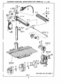
FOR PARTS LIST--SEE
Figuro W
a,i
i
2
PAGE
3
CP_SP/L_N
ACCP_-AP._
10_RNCH
RADIAL
SAW,
MODEl.
NO.
113.29003
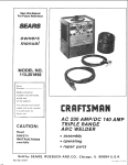
_d_ part_ illu_ted
in Figures 1 through 4 and listed under part numbers may be ordered through any Sears mfall or
teal! order store. Order parts by mail from the mall order store which serves the territory in which you live. In several
B_'tances part numbers are listed for COMPLETE ASSEMBUESo AI! parts are shipped prepaid w_in the I_m_ of the ¢an_
finentol United States.
WHEN
ORDERING
REPAIR PARTS ALWAYS
GIVE
THE FOLLOWING
INFORMATION:
I. THE PART NUMBER.
2. THE PART NAME.
3. THE MODEL
4. THE NAME
NUMBER 113.29003.
OF ITEM--RADIAL
SAW.
Do not use Ref. Numbers when ordering Repair Parts, always use Part Numbers.
FIGURE
Ref. No.
Part Non
I
Description
1
2
3
30469
30470
5.1374
,4
5
6
7
30472
30473
5.602
5.1243
8
9
S-1385
30474
10
11
S-1336
5.1255
12
30475
13
5-1337
14
30476
Radla| Arm
15
16
30671
5-1393
Column Tube Assembly
17
5-127
18
30479
19
30661
20
5-1342
21
22
30662
30482
Adapter Plug
Cord with Plug
PARTS
Ref. No.
LIs'r
Description
Part No.
*Pan Hd Mach Screw 8_32x5/16
23
24
5.1266
30483
_'Pan Hd Type 23 Screw 6-32 x 1/4
Cord Clamp
25
26
30484
30485
Cover Plate Assembly
*Pan Hd Moch ,Screw 10-32 X 3/8
27
28
30704
30654
_Pan Hd Mach Screw 6-32 x 1/4
29
30
31
32
33
34
30655
30489
30490
30491
5-t265
304?2
35
5-1387
36
30493
37
5.1216
38
30494
39
9-3240
40
41
42
43
30495
3540
9,3247
9-3220
Arbor Wrench
tDado Set
44
45
46
30496
9.29007
9-2536
tMotding
_Fiber Washer .140 x _250 x 1/32
Indicator #I
_Fil Hd Mach Screw I/4-28x
1
*Med Lock Washer I/4 SAE
Radial Arm Cap
_Pan Hd Tyloe B Sheet Metal 5crow
#8 x 3/4""
*Hex Hd Cap screw 3/8-16x3/4
elnternal Shakeproof Lockwasher 12-20
Arm Latch
Brake Shoe
*Socket Hd Cap ,Screw 5/16-18 x 5/8
Arm Lock Screw
Arm Lock Pin
Sw_h Key
Switch Cover
Switch
Trim
Arm Latch Shah Assemb|y
Retaining Ring
Spring Support Washer
Arm Latch Spring
Trim C¢_p
*Pan Hd Moth Screw 10-32x3/4
Handle
*Truss Hd Mach Screw 1/4-20 x 1-7/8
with Lockwasher
Wing Nut
*Steel Washer 11/32 x 7/8 x 1/16
Collar
tl0"
Kromedge Chisel Tooth Saw
Blade
Shaft Nut
tMordlng Cutter Head
Shaft Wrench
Cutter Guard
1Work Light
* Standard hardware ffem -- may be purchased locally.
"/"Stock item- may be secured through the Hardware Department_ of most Sears or SlmpsonsMolt Order Houses.
Sear_ Retail Stores or
NOTE: Shipping and handling charges for _tandard hardware items (identified by*) such as nuts, s_crew_,washers, etco
make buying these items by mall uneconomical. To avoid sblpptng and handling charges, you may obtain most
of these locally.
l
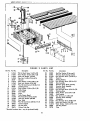
FaGURE
1Ref.Hoe Part No.
1
2
3
4
5
6
7
8
9
10
11
12
13
14
15
16
17
18
19
20
21
5-1346
S-1284
5-1255
5-t258
30497
5-1216
5-1343
5-1347
30498
$-1214
30501
30499
30500
30502
S-1348
S-1349
30503
S-1350
30672
30673
30674
PARTS
De_r_i:_on
Ref. No.
*Rd Hd Mace Screw I/4-20x7/8
_'Steel Washer 17/64 x 5/8 x 1/32
*Med Lock Washer I/4 5AE
*Hex Nut 1/4-20x7/t6x3!16
Channel
*Steel Washe_ 11/32x7/8_I/16
*Med Lock Washer 5/16 5AE
*Hex Hd Mace Screw 5/16-18 X 1/2
Adjusting Screw
_Steel Washer 17/64 x 1/2 x 1/32
Table Clamp
Front Table
Fence
Table Spacer Board
_Hex Nut 3/8-16 x 9/16 x 21/64
Med Lock Washer 3/8 SAE
Rear Tab|e
*Hex Hd Mace Screw 3/B-16 x 1-1/8
* Standard hardware
Column Support
Sac Set Screw
Column Tube Key
item-
LIIST
may be purchased to¢olly_
4
Part No,
22
23
2.4
25
26
27
28
29'
30
31
32
33
34
35
36
37
38
39
40
30509
30510
5-1353
30511
30512
5-1354
30676
3O5O8
30678
30515
5-1355
30516
S-1356
30675
5-1389
30518
30517
5-1359
5-1358
41
42
43
S-1375
30604
30718
.Description
End t_lay Washer #8 (as re€I'd)
E|evatlon ShaFt Be=rlng Bracket
+He× Hd Moch Screw 1/4-20x 3/4
Piv_ Pin
l],earing Bracket
_Hex Hd Mace Screw 3/8.16 x 5/8
Base Assembly
Elevation Crank Shaft Assembly
Elevation Shaft Assembly
Retaining Plate
+Hex Hc_ Mock Sc_re_ 5116-18x7/8
Retaining Ring
tSteel Washer .515 x 7/7 x 1/32
Stud Fastener
"Sac Set Screw 1/4-20x3/8
Elevation Crank Assembly
Nameplate
*Hex Hd Mace S_rew 10-32 x 3/8
_Med Lock Washer #10 SAE
_'5teel Washer 13/64 x 7/16 x t/16
Oil Sling Washer
Plug
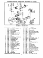
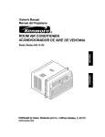
Figure 3
...........
,
u,,,,
,, ,.
"_-SS
i
i,,,,.............
FIGURS
Ref. blo_ Part No.
1
2
3
4
5
6
7
8
9
10
11
12
13
14
15
16
17
18
19
20
21
22
23
24
25
26
27
28
29
30
31
30519
5-1361
30679
5-1343
30521
30657
5-1392
30680
30524
30527
30682
5-1363
30683
30684
30685
30686
30536
30687
30681
30615
30688
5-1394
30538
30539
30540
30541
30542
30543
30544
30545
30689
:_ PARTS
Description
Swivel Latch Pin Handle
*Hex Hd Mach 5<:rew 5/16-16 x 1-I/2
RetainingPlate
*Med Lock Washer 5/16 SAE
Swivel Latch Sp_ing
Swivel Latch Pin
*Steel Washer .328 x 3/4 x 1/16
BailRetainer
Carriage BallRace, ImP1hand
Ball
Speed Nut
*Hex Hd Math Screw 5/16-18 x 2-1/4
Rip Scale Indicator
Carriage Cover, left hand
Eccentric Bushing Sc.mw
Eccentric Bushing
Carriage Lock Knob Assembly
Carriage Lock Shoe
Ball Retainer, r'_ghl hand
Carrlage Ball Race, right hand
Carriage Cover, right hand
*Pan Hd Math Screw 8-32x3/8
Saw Guard Assembly
Discharge Elbow
Wing Screw
Anti-Kick Back Pawl A_.sernbly
X-Washer
Anti,Kick Back Pawl
Rod
Crow Pin
Bevel Latch Pin
* ,_landard hardware item _ may be purchased locally,
5
LIST
Ref. No.
Part No.
32
33
34
35
36
37
38
39
40
41
42
43
44
45
46
47
48
49
50
51
52
53
54
55
56
57
58
59
60
61
62
30690
30548
30547
30546
30505
5-1390
30.567
30566
30618
30565
30691
30660
5-1366
S-1255
30562
30692
30558
30557
63
5-,1372
30663
30556
30606
30664
30551
30552
5-1391
5-1385
30559
S-1365
30693
30592
Description
Latch Pin Handle Retainer
Latch Pin Spring
Disk
Retaining Ring #2
Hex "L'" Wrench 1/8 ocro"_ flats
_Soc Cup Point Set Screw 1/4-20 x 1
Bumper #2
Yoke Clamp Assembly
- Dust Cover
Bumper
Corrlage
Latch Pin Housing
*Hex Hd Moch :Screw 1/4-20x7/t6
_Med Lock Washer 1/4 SA.E
Motor Support Bearing
Yoke
Lock Screw
Yoke Clamp Handle Assembly
Index Handle _rake Shoe
Expander
Bevel Index Handle
Index Handle Washer
Pressure Pad
Bevel Lock Knob Assembly
Hex "L" Wrench 7/32 acro. fiats
*Pan Hd Math Screw 6-32x3/16
_Fiber Washer .140 X .250 x 1/32
Indicator #2
*Sac Hd Cap Screw 5/16.18 x 1-1/2
Latch Pin Handle
Bevel Scale
_#2x 1/8 Type U Drive Screw
8 1623
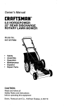
"\
\
\
\
I
I
J
•..._-_...--20
/
/
1
1_/
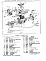
BLACK
T0
/
11 12
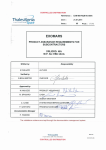
GREENTO GREEHON PLUGAND CORD{SEEiTEM3 FiG I)
WHffETO SWFICH=3
BLACKTO SWIICH=1
F_gore 4
FIGURE
Ref. No.
1
2
3
4
Part No.
__,T_em.
30696
5-t367
30697
30570
5
5-1371
6
7
O
30571
30572
30719
*Steel Washer 1-9/16 x 1-27/32
x .010 (as req'd)
Bearing
Bearing Retainer Plate
End Shletd #2
30574
S.1368
30575
30698
30577
Hog Ring
*Fiber Washer .380x
Insulating Bushing
Assembled Rotor
Baffle Plate
9
10
11
12
13
14
15
16
17
18
5-1227
30578
_
30580
30720
4
PARTS
9".s
DescHptlon
Motor (Less Guard Stud)
Stator Screw
*Pan Hd Much Screw With Lockwasher
Stator .Screw @2
Guard Stud
9/16,_ 1/32
LiST
Ref. No.
19
20
21
22
23
Part No.
30573
5-109
30582
30613
30583
24
25
26
27
28
5-1285
30700
5-1369
30586
30677
29
30
31
32
33
30588
$-1370
30701
30590
30619
"Description
Wire Connector
*Hex Nut 8-32 x 11/32 x 1/8
Shaft Cap
Card Clamp #2
Grommet
*Pan Hd Much Screw 8-32 x 3/8
Capacitor Clamp
*Pun Hd Much Screw 6-32 x 5/16
Capacitor
Protector
Relc_
*Pan Hd Much Screw 6-32 x 7/16
Assembled Lead #1
Assembled Lead @2
#16 AWG U.L Approved
WL,o S-1/2"
*Pan Hd Much Screw 8-32 x 1/4
Cord
Assembled Staler _,'_?
5wing Washer
End Shield
34
None
StanduTd hardware item - may be purchased locally,
6
30702
30670
Nameplate
Operating Instructions & Parts List
for Craftsman Aco'ra-Arm 10" Radial
Sow, Model 113.29003
Your
I.
2.
3o
4_
5.
6_
7.
8_
9.
10_
11.
12,
13,
14,
15.
16o
17o
18.
19.
Arbor Wrench
Shaft Wrench
Table Clamp
Adapter Plug
Yoke Clamp Handle
Radial Arm Indicator
Carriage Lock Knob
Rip Scale Indicator
Swivel Latch Pin Knob
Latch Pin Handle
Switch Key
Arm Latch Handle
Bevel Index Handle
Discharge Elbow
Anti Kick Back Pawl Assembly
Bevel Lock Knob
Bevel Index Scale and indicator
Elevation
Crank
Hex "L" Wrenches
Figure
5
ASSEM BLI N G -ADJ USTIN G
CONNECTING
For 230 volt operation, see connecting instructionson motor
nameptateo Also see the "Warning Label" on the rear of
the saw base°
THE MOTOR TO THE POWER SUPPLY
Motor Spec_cations
"'IMPORTANT" The fat!owing wire sizes ore recommended
for connecting the motor to o power source for TROUBLE
FREE OPERATION.
115/230 volt, 10/5 amps, 3450 RPM, 60 cycle, alternating
current (AoC. only) single phase, non-reverslbteo Rotation:
clockwlse viewing saw blade end of motor shaft.
The motor as shipped is connected for 115 volts_ For 115
volt operation see Figures 6 and 7 for connecting plug
and cord from saw into 115 volt receptacle.
Length of
Concluctor
Wife Size R_quired
(Ame_iconWire Gaug_ No,)
115
Safety Precaution
The saw motor is equipped with a manual reset, therme]
oveHoad protector. If during operation this protector opens
the line, immediately turn the switch "Off". The protector
can be closed again after the motor has cooled by firmly
pushing the red button on the capacitor cover until the
protector snaps into the running position. Do not tap or
strike the reset button_ This protector is not intended to
take the place of a fuse as the protector will not provide
protection against overloads or short circuits in the lines
leading to the motor. The motor should not be operated on
a load which ca usesthe protector to open the line frequently°
For circuit protection use a "Fustat" or "'Fusetran" fuse
--15 ampere fuse for 115 volt operation and 7½ ampere fuse fop 230 volt operation.
Volt
Lines
50
feet
or
tess
No,
12
100
feet
or
less
No.
10
• 100
feet
to 150
feet
No,
8
150
feet
to 200
f_et
No.
6
200
feet
to 400
f_et
He.
4
50
100
100
150
200
feet
feet
feet
feet
feet
or
or
to
to
to
230 Volt Lines
less
less
150 feet
200 feet
400 feet
No_ 14
Hoe 12
No. 10
No.
8
No_ 6
For circuitsof greater length the wire size must be increased
proporfiohally.
ALWAYSGROUND
PIGTAIL
_--_'_------_'_
TO
115 VOLT
SUPPLY LINE
SUPPLY
115 VOLTt|NE
PLUa
FROM
AND
SAW
CO_D
_
_)_
|
GROUND WtlE
PLUG
AND
CORD
FROM SAW
METAL t_ECEPTACLE _OX
MUST _E GROUHDED
TO
A COLD WATER
PIPE OR
TO THE ELECTRICAL
GROUND
OF THE INCOM|NG
"_
ADAFTER
GI_OUND LLtO
PLUG
POWER
_ITEM4, P_GUeE
S_
Figure
Figure 6
7
7
LINES
_OUHTING
THE SAW TO A WORK BENCH
The saw should be placed on a _itoble sturdy work bench
and posltlor,ed so that the elevation crank (figure B) is flee
to i'otate_ The ba_ of the saw must be mounted to a flat
•.urfoce on the work bench to prevent distortion of the saw
ase_The nuts, screws,and washers which attach the wooden
_ipping
skids to the saw base may be reed to secure the
saw base to the work bench. Check that saw is level or
sloped slightly to the rear so that carriage when undamped,
does not run ffwe]y to the front end of the radial arm.
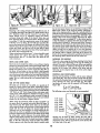
INSTALLATION
OF THE TABLE AND FENCE
1. Turn elevation crank to robe motor clear of shipping
brackets_
2. Remove shipping brackets from base.
3o Place front table on channels with notch in table forward and down as shown in Figure 8o
4_ Align holes in front table with three forward mounting holes in channels_ See Figure 8.
5o Assemble six machine screws and washers through six
holes as shown_
6_ Attach six lockwashers and nuts. Before tightening nuts
securely push table evenly toward rear of saw_ Tighten
nuts.
7, Lay fence in vertical position behind front table.
B Lay table _oacer board behind fence.
9_ Lay rear table with cut-out section forward behind table
spacer board.
10. lnstaff table damps as shown and tighten securely
against edge of rear table.
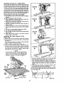
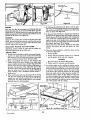
ADJUSTING THE TABLE PARALLEL TO THE
RADIAL ARM
1o Remove saw guard with holding washer and wing nut.
2_ Remove shaft nut and one loose collar on motor shaft°
See Figure 11.
. Insert arbor wrench between collars on motor shaft.
Figure 9. Tighten shaft nut by hand.
4. Tighten radial arm handle (item 12, figure 5)_
5_ Loosen carriage lock knob (item 7, figure 5) and turn
elevation crank until end of arbor wrench just touches
the tobte top thus permitting the wrench to be swung
back and forth_ See Position 1, Figure 9. Mark this spot
and Positions 2, 3 and 4 with a pencil.
NOTE
Do not turn the elevation crank throughout the remainder of this procedure as the radial arm must
remain at the same height above the table while
checking at Positions 1, 2, 3 and 4 of Figure 9,
POSITION
1
POSITION
2
POSITION
3
POSITION
4
Figure 9
6. Pull motor to Position 2. Wrench when moved back and
forth should just contact table tap as in step 4.
7. Turn arm latch handle (item 12, figure 5) counterclockwise and pull out. Move arm to Position 3 of Figure 9.
Tighten radial arm handle and repeat procedure of
step 6.
ft. Move radial arm to Pasltlon 4 of Figure 9, tighlen radio|
arm handle and repeat above procedure.
If contact between the wrench and the table top is not the
same at all four positions the table can be leveled as follows: (See Figure 10)o
3
1
1_ Loo_n
Tne
Qamplng
_or_w'_ _wn_
mJ _tl
_m
:_IUAICII_
UM" :_AW ISI.AU= _
In" IAnLC lur
1. Place edge of combination square or accurate steel
square on table top and position as shown in Figure 13.
Square must be held firmly against table tap°
2. When blade is _uare to the table no light will be v_ible
between square and face of saw blade. Do not allow
square to rest on saw teeth.
If light is visible between steel square and face of sow
blade adjust as follows:
a. Loosen bevel lock knob (Item I, figure 13). Use 7/32
hex "L" wrench and sllghfly loosen four socket head
screws (item 2, figure 13).
b. Hold motor shaft at one end and tilt motor in proper
direction until saw blade is square to table top. See
Step 2 above_
c. Retlghten socket head screws (Item 2, figure 13) and
bevel lock knob (Item 1, figure 13).
d. Recheck blade _uareness to table top since tightening of screws may have shifted motor.
e. Indicator (item 3, figure 13) should read 0 ° on bevel
index scole_If not, loosen screw and adjust indicator.
Retlghten screw.
CHECKING COLUMN TUBE KEY
if excessive radla| arm movement is noticed even though the
arm is locked in position, check the fit of the column tube
key (Item 2, figure 14) and the keyway in the column tube.
_€;,nne'ls
• (item 2).
2. Adiust nuts (Item 3) by alternating loosening and tightening so that the channels are moved up or down an the
a_justing screws (Item 4) in the desired direction.
3. When channels are properly adjusted the arbor wrench
wifl just contact the table top when swung back and forth
at Positions 1, 2, 3, and 4 of Figure 9_ Tighten clamping
screws (Item 1). Recheck the four positions to insure that
no change has occurred.
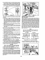
ATTACHING
THE SAW BLADE
1. Remove shaft nut and one loose col|arm
2. Place saw blade on motor shaft taking care that saw
blade teeth are in some direction as shown in Figure 11_
3. Replace other loose coltar and shaft nut° Smooth face
of €ol|or must be away from saw blade.
,4. Use arbor wrench (item 1, figure 12 on motor shaft nut
and shaft wrench (Item 2, figure 12) on slot in motor shaft
to tighten shaft nut.
CAUTION:
SHAFT NUT
HAS LEFT
HAND
THREADS
To Loosen Shaft Nut
" ° "_
Figure 11
Figure
CAUTION:
SHAFT NUT
HAS LEFT
HAND THREADS
1. Adjust by loosening the socket set screw (Item I, figure
14), using the 7/16 hex "'L'" wrench°
2. Pressvigorously against the rear of the column tube key
(Item 2, figure 14) or C-clamp the key while slightly
rocking the radial arm back and forlh. This causes the
key to seat properly in the keyway°
3o Tighten the set screw (item 1, figure 1`4) securely whffe
maintaining pressure on the key°
SQUARING THE CROSS CUT TRAVEL TO THE FENCE
1_ Set radial arm at 0 ° index position and tighten arm
latch handle_ See Page 11 "Angular
Movement and
Locking of the Radial Arm" for the most positive and
ro Tighten
Figure
Shaft
12
14
Nut
accurate sewings at an index Posilion,
2
Figure
Figure 13
9
15
2o Lay combination square or accurate steel square against
fence as shown in Figure 15 and position until it just
contacts a blade tooth (See A, figure 15). Mark this tooth.
3_ When the carriage is moved back and forth on radial
arm saw toofi_"A" should iust touch square at all po_itions.
Figure
17
CHECKING THE SAW BLADE FOR HEEL
(LEFT AND RIGHT)
tf saw tooth "A" does not touch square as in step 3, adjust
as fellows:
a. If saw tooth "A" (Figure 15) moves away from the square
when moving the blade from the rear to the front of the
table, completely loosen the three screws holding the
table to the channel on the |efthand side of the table
_nd slightly loosen those on the right side of the tableo
Slightiy tighten the left table clamp (Item 1, Position 4,
Figure 9)_
bo Tighten all table screws first, then both table damps.
Recheck blade squareness again.
c. Reverse this procedure if tooth "'A" moves into the square
when moving the saw blade from the rear to the front
of the table.
Using a scrap piece of one-lnch lumber approximately six
inches wide, lay it on the table against the fence on the left
side of the blade. Position the board ta permit a three-inch
piece to be cut from the right end holding the beard firmly
against the fence wffh the left hand. Turn the key switch
"On" and commence the cut by pulling the saw forward
through the board until the front half of the saw blade clear_
as _hown in View A_ Turn the switch "Off" and atlow the
saw blade to come to a complete _op while the rear portion
of the blade is r_itl in contact with the wood, Marks on the
face of the board indicate left heeling. Check face of cut
board. See View A_ To check for right beefing repeat the
same cut from the right side of the blade. Check for heel
marks° See View B.
tn some cases, the above adjustment may not be sufficient.
if this is the case, adjust as follows:
_. Remove three screws (Item 1 and 2, figure 16), indicator
(Item 3) and radial arm cap (Item 4).
b_ Turn arm latch handle 1/2 turn counterc!ockwi_ to release brake, Do not pull out_
c. Slightly loosen (do not remove) two hex head screws
(Item 5) inside of column tube,
do Move radial arm in proper direction to make saw tooth
"'A" (Figure 15) follow edge of square when checking.
e. Retightee hex head screws (Item 5, figure 16) and arm
latch handte.
f. Recheck blade tooth "A" travel with square.
g_ After blade is square to fence reassemble radial arm
cap and indicator using screws (item 1 and 2, figure 16).
Set indicator at 0 °.
PRELIMINARY CROSS-CUT AT THE 0 _ POSITION
1o Attach saw guard (Item 1, figure 17) washer (item 2) and
wing nut (Item 3) to motor and motor s_tud(Item ,4).
2. Pull motor forward of fence so that blade is flee to rotate°
3. Lower radio1 arm untff sow blade just clears table top.
,4. Tighten carriage lock knob (Item 5, figure 17).
CAUTION
Before cutting always be sure that the arm latch
handle is locked fully clockwlse. (Item 8, figure 17.)
5. Plug in power cord to receptacle.
6. Insert switch key (Item 6, figure 17) and turn "On".
7. Lower rodial arm until blade cuts into tabte top 1/32".
THIS tS ALL THAT IS NECESSARY°
NOTE
The piece of wood must be held firmly against the
fence and not permitted to move while the saw
blade is coming to a stop°
_0
"r_VEL
,_OE _U_VEL
%.
/_LnK
IN
DOA_O
St,ADE
HEELING
TO LEFT
_'_ :ll _'''
_
Exaggerated
ktAf_
_
VIEVV
A
View
V|_
B.
of Heeling
IN
_AIO
BLADE HEELING
TO li:IGHr
Condition
To correct for heeling (left or right) proceed as fallows:
1o Remove left hand carriage cover (Item 1, figure 18)o
To cut a blade clearance groove in the table and fence hold
the bevel index handle (item 7, figure 17) with the left hand
and loosen the carriage lock knob (Item 5, figure 17) with
he right hand. Slowly pull the motor with the left hand out
to the e_reme end of travel and then push the motor back
through the fence to the e_treme rear posltion_Turn the key
Jwitch "OFF",
Figure 1 8
10
5. Refighten the two hex head machine screws (item 3,
figure 18) and relock the yoke by pushing the yoke clamp
handle toward the rear of the saw.
6. Recheck for left and right heel as before.
7o When the heeling condition is corrected the face of the
board will shaw no marks when cut from either side
of the blade.
B° Replace carriage cover_
2.* Loosen yoke clamp handle (item 2, figure 18) by pulling
the. handle horizontally toward the front of the saw.
3. Slightly loosen the two hex head machine _rews (item 3,
figure 18).
4. Rotate the yoke (item 4, figure 18) very slightly oppo_ite
to the direction of heel. (For left heel, rotate yoke clockwise; forrightheel rotateyoke counterclockwise.)
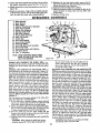
CONTROLS
OPERATING
1.
2.
3_
4.
5o
6.
7.
8.
9.
10.
1 Io
12.
13_
14_
15.
16.
17.
18.
19.
Arbor Wrench
Shaft Wrench
Table Clamp
Adapter Plug (Except in Canada)
Yoke Clamp Handle
Radial Arm Indicator
Carriage
Lock Knob
Rip Scale Indicator
Swivel Latch Pin Knob
Latch Pln Handle
Switch Key
Arm Latch Handle
Bevel Index Handle
Discharge Elbow
Anti Kick Back Pawl Assembly
Bevel Lock Knob
Bevel Index Scale and indicator
Elevation Crank
Hex "'L" Wrenches
NOTE:
WHEN ORDERING REPAIR PARTS
REFER TO PARTS LIST FOR CORRECT PART NUMBER.
14----.._
Figure
the arm latch handle (at end of radial arm) to
prevent damaging the arm lock pln_ If damage
occurs, the radial arm wiff not index properly at
0 ° and 45_ left or right.
MOVEMENT AND POSITION OF THE MOTOR IN THE
YOKE are,controlled by the latch pln handle (item 10, figure
19) and beveZ lock knob (Item 16, figure 19). The bevel scale
indicates the angular position of the motor with respect to
the horizontal from 0 _ to 90 ° in either vertical pos'rtionoThe
latch pin handle automatically indexes the motor at 0 °, 45 °,
and 90 ° up and da'_n. Lift to release. At any other position the latch pin handle isnot engaged. The bevel lock knob
locks the motor to the yoke when the motor is in any position. Locking is clockwise; unlocking is counterclockwise.
MOVEMENT AND POSITION OF THE YOKE are controffed by the swivel latch pin knob (Item 9, figure 19) and
the yoke clamp handle (Item 5, figure 19). The swivel latch
pin automatically indexes the yoke at each 90 ° position and
two 45 ° positions_ Lift to release_ The yoke clamp handle
locks the yoke to the carriage in any position. Pull to release.
Push to tighten. When "in Ripping" it may be desirable to
have more flee table in front of the saw blade than is ohtainable when the radial arm is at the 0 ° posltlon_ With
the blade in th normal cross-cut position index the radial
arm to 45 ° left and lock it. Then loosen the yoke clamp
handle and index tile yoke 45 ° clockwise_ Redamp the
yoke clamp handle. The added free table space is now to
the right of the blade and ripping should be done from the
right side of the table. The reverse is also true for "Out
Ripping" by indexing the radial arm 45 ° right and indexing the yoke ,45° countercTackwlse_ The added table space
is now ta the left of the blade and ripping should be done
from the left s_de of the table.
CAUTION: Under these two conditions the In-Rip
and Out-Rip scales cannot be used.
RAISING AND LOWERING
THE RADIAL ARM is accomplished by the elevation crank (Item 18, figure 19). One
complete turn of this handte will raise or lower_the radial
€l/'m
_9
_,_".
LOCKING THE CARRIAGE TO THE RADIAL ARM
is
accomplished by the carriage lock knob (Item 7, figure 19).
Turn the knob clockwise to lock; counterclockwise to unlock.
ANGULAR MOVEMENT AND LOCKING OF THE RADIAL
ARM are controlled by the arm latch handle (item 12,
figure 19). The radial arm can be rotated 360 ° and locked
in any position. The arm is unlocked from any position by a
slight counterclockwise rotation of the arm latch handle
and is locked in any position by rotating the arm latch
handle clockwise until tight. The radial arm has positive
stops at 0 ° and 45 ° left and right, and is released from
these index positions by unlocking and pulling out the arm
latch handle (Item 12, figure 19). Due to positive arm
locking at the index positions, the arm latch handle
may be difficult to pull out. A few turns to the left will
release i|.
For most positive and accurate settings at the index positions, the following is recommended:
1. if the radio1 arm is already indexed, unlock and pull
out the arm latch handle and move the radial arm off
of the index position. Release the arm latch handle.
2. Before moving the radial arm to the desired index position, turn the arm latch handle (item 12, figure 19) just
1/4 turn counterclockwise from the locked position.
3. Move the radia! arm into the index position (do not
bump or jar) and hit the face of the arm latch handle
solidly with the palm of the hand.
4. Lock the radial arm by turning the arm latch handle tufty
clecl_,vise.
CAUTION:
When moving the radial arm in any
direction beyond _° left or right, always pull out
11
Figure
1. Adjust by loosening the socket set screw (item I, figure
22), using the 7/16 hex "t" wrench.
2. Prexs vigorously against the rear of the column tube key
(Item 2, figure 14) or C-clamp the key while slightly
rocking the radial arm back and forth_ This causes the
key to seat properly in the keywoTo
3, Tighten the set screw (Item 1, figure 22) securely while
maintaining pressure on the key.
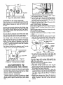
ADJUSTMENT
OF RiPSCALEINDICATORS
Whenthefenceis in itsnormalposition
(nextto thefront
table),indextheyoke90 ° from the €_oss-cut position so
that the blade
is between the motor and the fence° Lock
YOKE CLAMP HANDLE ADJUSTMENT
The normal locking position of the yoke clamp handle (item
1, View A_ figure 23) is midway between the two sides of
the yoke.
When the handle strikesthe yoke before locking, the handle
may be adjusted as follows:
1. Remove sow guard and blade.
2. Set yoke clamp handle to Position A, Figure 23. (Mid
Move the molar along the radial arm uoti_ the blade, when
spun by hand, just _uches the front face of the fence (See
Figure 20)° The indicator (Item 8, figure 19) on the "In-Rip"
scale should now read 0. If not, shift the position of the indica|at to read 0.
The same indicator should also read correctly on the "'OutRip" scale when the blade is in the out-rip positlon_ This
indicator should be reset with any blade change.
way.)
3. Remove lock screw (Item 3).
4o With off-set screw driver turn slotted end of the yoke
clamp (Item 2) counterclockwise until a slight snugness
of the yoke clamp handle is felt at Position A, Figure 23.
The "Out-Rip"
scale on the left side of the radial arm is
only used when the fence is in its extreme rear position
against the table clamps and the blade is in the out-rlp
position. The some method of adjustment is used for this
cote indicator except that the blade is positioned as shown
so that 9°° is measured between the fence and the nearest
blade tooth. (See Figure 2I).
NOR/€_
a___s
L LOCKING
G _osmoN ou_ To WEAR
1710N
..-..3._
_
""
LOOSENED
_SITION
LOOSENED
The indicator should then be adjusted to read 9" an the
"Out-Rip" _cale on the left side of the radial arm_
POSitION
MEASURE
FROM FENCE
TO NEAREST BI.J_DE
TOOTH
Figure 23
A
NO_U,_,_OC_NG POSlnON
5o To replace lock screw align holes in yoke clamp with
hole in yoke by a slight odiustment of yoke clamp using
off-set screw driver° Insert lock screw and tighten.
CARRIAGE
hEAR
To test for looseness in the carriage, firm|y grasp the carriage (Item 1, figure 24) at the levet of the baff races and
apply a firm rocking motion.
Noticeable looseness may be adiusted as follows:
1. Remove sow guard and blade.
2o Place block of wood on table under motor and turn
elevation crank until weight of motor just rests on block.
3. Remove carriage lock knob assembly (Item 2, figure 24)
and carriage cover (Item 3, figure 24).
4. Loosen 3 hex head machine screws (item 1, figure 25),
eccentric hold-down screw (Item 2, figure 25) and two
adjusting set screws in the holes on the side of the carriage (Items 5, figure 2S)o Use 1/8 hex "L" wrench on
set screws,
5_ Rotate eccentric bushing (Item 3, figure 25) clockwise to
obtain snug fit. The bali retainer (Item 4, figure 25)
should be guided at both ends by hand to prevent
cocking°
T,/_ LEg._
I
Figure 21 .-Out-Rip
Position of Blade
ADJUSTMEHT$
TO
COMPENSATE FOR WEAR
Even though the finest materials and procidon workmanship
have been u_ed to minimize wear it is reasonable to expect
some wear. Adjustments have been built into your Croft_
man sow to reduce or eliminate this wear.
COLUMN
TUBE KEY ADJUSTMENT
:f excessive radlat arm movement is noticed even though
,t_e arm is locked in position, check the fit of the column
tube key (item 2, figure 22) and the key'way in the column
tuber
12
Do not lubricate bevel latch pin (Item 31, figure 3) in yoke.
DO not lubricate between radial arm cap (Item 12, figure 1)
and radial arm_
6. Retlghten all hex head scTew and _ntric
bold-down
_rew. (Do not allow eccentric bushing to rotate when
ttlghtenlng.)
7. Correct adjustment exists when there is no play between
the carriage and radial arm, and yet the carriage moves
freely. After adjustment is completed snugly tighten the
two adjusting set screws. Caution: Do not o_rtlghten.
8. Replace carriage cove_ and lock knob ossernbly_
PERIODICALLY LUBRICATE THESE POINTS
Use SAE No. 10-30 Auto Engine Oilo
Apply a few drops of all along the swivel latch pin (item 6,
figure 3) only ff the pin has a tendency to stick.Remove the
left-hand carriage cover and use all sparingly to prevent it
from getting on the ball bearings or races.
A light film of oil can be wiped on the face of the column
tube (Item 15, figure 1) and keyway to lubricate the fit
between this part and the key and column support (Items
21 and 19, figure 2).
Apply a few drops of all to the bearing surfaces of the
elevation crank shaft assembly (Item 29, figure 2). An othng
hole is provided in the elevaffon shaft bearing bracket (Item
23, figure 2) to facilitate the lubrication of the rear bearing
support.
The thread on the elevation shaft assembly (Item 30, figure
2) can be lubricated through the oiling hole in the center
of the radial arm cap (Item 12, figure I).
STANDARDSAW OPERATIONS
CROSS, CUI"rlNG
Crass-cuttlng is the sawing of wood across the grain. Planks
ore milled with the grain running the length of the plank_ If
a straight cross-cut is desired, the board is placed on the
saw table against the fence so that the grain is parallel to
the fence. See Figure 26.
PROPEROPERATINGPROCEDURES
DRESS PROPERLY -- Operation of the saw is simple, safe
and easy-when properly done. Always be atert_ Do not
wear a tie or other loose artlcles. Keep long sleeves down
with cuffs fastened or wear short sleeves. NEVER STOP
BEING CAREFUL. One moment of inattention can cost you
a painful injury.
NOTE
When cross-cuttlng normal pieces of lumber, the
long end of the board should be placed to the left
of the saw blade as the board is normally held by
the left hand during operation_
AVOID
AWKWARD
HAND POSITIONS-*Do
not get
hands into a position in which a sudden slip can cause them
to move into the saw blade. NEVER OPERATE THE SAW
WITH THE ARMS IN A CROSSED POSITION. Never hold
work on right side of blade with left hand while pulling saw
with the right hand Do not attempt flee-hand cros_.cuttlngo
Use a push stickwhen hand gets too close to the blade in o
ripping position.
NEVER TWIST WORK --Twisting work will bind blade and
cause a kickback_
Safety Precaution
The motor is shipped with a shaft cap (Item 21,
figure 4) threaded onto the stub end of the motor
shaft_ When this shaft end of the motor is not being
used, this cap should always be in place.
The radial arm must be positioned at 0 ° as indicated by the
radial arm position indicator. The arm latch handle must be
indexed and tightened_ See page 11 "Angular Movement
and Locking of the Radial Arm" far the most accurate setting
at the 0 ° index position. The yoke must be indexed at the 0 °
position, making the saw blade perpendicular to the rip
fence, and the yoke clamp handle placed in the locked pos_..
fion. The bevel •index handle must be positioned
at 0 o , €IS
indicated by the bore| scale, and Iocked_ Turn the elevation
crank to lower the saw until the btade teeth are approxlmately 1/32" below the table surface in the saw slot
made when performing the "PREI.IMINARY CROSS-CUT
AT THE 0 ° POSITION". Push the saw carriage to the rear
of the radial arm so the blade is behind the rip fence. Adjust
the saw guard so the bottom is parallel to the table and set
the antl-klckback pawl assembly so it iust clears the board
to be cut. Turn the switch key "On" to start the saw motor.
Hold the board firmly against the rip fence with the left hand
and grasp the bevel index handle with the right hand. The
cut is then made by pulling the carriage forward until the
LUBR|CATriON
Your saw is a fine machine and should be given the best of
care. If kept clean and properly lubricated, it will give many
years of trouble-free service° Before describing the various
points which may periodically require lubrication, IT 15
MORE IMPORTANT TO FIRST MENTION THE VARIOUS
SPOTS WHICH SHOULD NOT BE LUBRICATED°
NO
LUBRICATION
REQUIRED
Do not lubricate any ball races or any ball bearings.
Do not lubrTcate bearing fit of bevel index handle (Item 52,
figure 3) in yoke.
Do not lubricate the motor bearings° These are sealed ball
bearings and require no added lubrication.
13
At the opposite end of the guard, loosen the wing screw
holding the anti-kickback pawl assembty and lower the
assembly until the tips of the pawls are 7/8" below the top
_Jrface of the board to be cu/_ Retighten the wing screw
saw _lode cuts through the work_
The carriage will tend to move toward the operator so be
,prepared to restrain it by keeping your arm straight from
fife shoulder to the wrist, When the cut is complete, the saw
should be returned to the back of the radial arm and the
swltch key turned "Off".
it will be noticed, that the
saw blade tends to feed itself through
the work
due to the rotation of the blade and the direction of
feed. Therefore, the operator should develop the habit
of holding his right arm straight from the shoulder
to the wrlst_ After this method is used a few times the operator will find that it is necessary to roll or rotate the body
from the waist up. If this method is followed, it will become
apparent that very little effort is required on the pert of the
operator to move the saw blade through the work, and in
most cases, the right arm is used merely to control the rate of
feed of the saw through the board_ It will also be found that
when cross-cuttlng a thick board it wilt be necessary to retard
movement of the saw through the work. By holding the right
arm (right hand normally grips the saw handle) _alght, the
operator can easily control the rate of feed, thus prever_ing
the saw blade from overfeeding and stalling the saw motor.
This must be avoided whenever possible. In some casesit may
become necessary to cross-cut tong boards which extend
over the saw table on one, or both sides. This can cause
buckling of the board and bind the sow during the cut, To
eliminate th;s condition the ends of the board should be sup-
IN-RIPPING--In-rip
refers to a posltion when the blade is
between the motor and the fence and parallel to the fence.
See Figure 28. To place the sow in this position, unlock the
yoke, disengage the swivel latch pin and rotate the yoke 90 °
clockwise (viewing it from the carriage) until the swivel latch
pin automatically indexes the yoke 90% Relock the yoke.
See "'Adjustment of Pointers" to check accuracy of "lnoRip"
scale reading. Position the motor on the radial arm until the
pointer on the "In-Rip" scale indicates the desired width of
the finished cut board_ Tighten the carriage lock knob securely. Position the discharge elbow on the guard _o that
sawdust will be blown toward the rear of the saw. Turn the
saw "'On" end lower the saw blade until it cuts into the table
top about 1/32",, Turn the saw "Off"°
Haw adjust the
saw guard and anti.kickback pawl assembly as described
in the paragraph "Ripping".
The board to be ripped
must be fed into the saw blade from the right side of
the table, therefore, the normal position for the operator
is also at the right side of the table. With the left hand safely
clear of the blade and holding the board to be ripped down
against the table and against the face of the fence as a
guide, use the right hand to feed the board into the saw. The
left hand should remain stationary, serving as a guide only.
As the right hand approaches the left hand, hold a push stick
with the right hand to complete the cut° Do not leave a long
board unsupported so that the spring of the board causes it
to shift on the table_ A support like that described in "Cross_
Cutting" can be used to support the board behind the blade;
and if the board is very long, use another support in front of
the saw° R_pped boards up to 8_" wide can be cut in
the In-Rip posltiom
ported. Figure 27 illustrates a typical support which can be
made and used to facilitate cross<utting of long lumber°
RIPPING
Ripping is the sawing of wood with the grain. It is always
done with the help of the fence as a guide to position and
maintain the work at the correct width for the cut_ Because
the work is pushed along the fence, it must have a reason..
ably straight edge to make sliding contact with the fence°
Also, the work must make solid contact wlth the table sa that
it will not wobble or rock. Provide a straight edge, even if
this means temporary nailing of an auxiliary straight edge
board to the work_ If work piece is warped, torn the hollow
side down.
Use of the sow guard is always recommended; and the arrtikicEback paw! assembly shou|d always be used in both in-rip
or our-rip operations, Before ripping and after the saw has
been positioned prior to cutting, the saw guard and antikickback pawl assembly must be properly adjusted_ Loosen
the wing nut holding the guard to the motor and lower the
nose of the guard to within _" above the top surface of
the board to be cu_. Refighten the wing n_ securely.
OUT-RIPPING-_Ouf_rip refers to a position when the motor
is between the blade and the fence° Normally, this position
is only used when the width of the required ripped board
cannot be cut from the in-rip position. Ripped boards up to
181,_°' wide can be cut in the out_rlp position when the
fence is against the front table. If the fence is moved to the
extreme rear position against the table clamps, ripped
boards up to 25,%" wide can be cut_ To place the saw
in the out.rip position, the yoke must be rotated and indexed
90 ° counterclockwise from the crossocutposition and locked..
The same procedure far sawing is used except that now
the operator stands at the left side of the table and a push
stick is normally nat required°
CAUTION
The nose of the guard refers to that end of the
guard which is opposite to the end which mounts the
anti-kickback pawl assembly. Always rlp from the
nose of the guard. See Warning [.abel on guard.
F;gure 27
NOTE
For added table space in front of the blade see
"Movement and Position of the Yoke".
Figure 2B
14
Figure 29
Figure 31
RESAWING
two or mare passes_Space cuts so that they oveddp a trifle.
Dado work is done in the cross-cut position. Ploughing is
done in the ripping position. If the rip or plough position is
used the saw guard and anti-kickback pawl assembly should
be adjusted as described in the paragraph "RIPPING". Rabbeting is done in the vertical position. See Figure 31. When
rabbeting, the motor is indexed 90 ° to the vertlcat position
so that the blades are between the table tap and the motor
and the yoke is indexed 90 o clockwise and locked° The sow is
moved back on the radio1 arm and locked to the arm when
the amount of the blade extending forward of the fence is
equal to the depth of the rabbet desired, tf the depth of the
rabbet is large, do not attempt to cut it in one operation.
Lower the radial arm until the blades are in a position to cut
the desired width of rabbet in the edge of the board, The
bottom of the saw guard should be parallel to the fence and
the discharge elbow directed to the rear of the sown
Resowing is the cutting of thick boards into thinner ones_ It
is a ripping operatiano See Figure 29. Smalt boards-up to
2½" maximum wldth--can be resawed in one pass; but
larger boards up to S" maximum require two passes,
one pass along each edge of the board.r When two cuts
from opposite edges are required, these should be made
to overlap _,_" from the approximate center of the board_
If the first cut is too deep, the kerf will close and bind the
saw an the second cut, with danger of kickback° Also, when
the kerf closes, the two sides of the cut are na longer parallel
to the saw blade, and the saw will cut into them to spoil
their appearance_ Keep the same face af the board against
the fence when making both cuts.
When cutting boards thicker than 4"° a fence should be used
which extends 3½" above the table topr When cutting
boards thicker than 5", cut both sides and finish the cut
wlth a hand saw_
BEVEL AND
MOLDING
OR SHAPING
Th_swork is done using the Craftsman Molding Cutter Head
and a set of cutters depending on the type of molding cut
desired. This work is done with the saw in the some position
as that described for rabbetlng_ See Figure 32. Since the
position of the cutters with respect to the fence and the
table top can be adjusted any or all of the cutter shapes
can be used.
MITER CUTS
Bevel cuts can be made from either a crass-cuttingor ripping
position by tilting the blade to the desired angle. Miter cuts
can be made only from a cross-cutting position when the
blade and radial arm are at some angle other than 90 = to
the fence° A bevel miter cut is a cut which is both beveled
arid mitered. This cut is made with the blade and radial arm
set at the desired miter angle to the fence and then the blade
only is tilted with respect ta the table top to the desired beve!
angle. This cut is also referred to as a compound miter, See
Figure 30_
USE OF THE DADO
Figure 32
ROUTING
AND
DOVETAILING
Routing and dovetailing are done with the motor indexed
and locked 90 ° from the horizanta! except that this time
the externally threaded stub end opposite the normal blade
end is between the "motor and the table top. The foffowing chucks will mate with this external ½-20 thread: (See
Figure 33)°
0 '° to 1/,_" Key Chuck
5/64" to I/2" Key Chuck
HEAD
The dado saw or head, as it is called, is a special set of
blades for cutting grooves and dados_ Craftsman 8" Krom.
edge Dada Set can be purchased at any Sears Retail Store
or Mall Order House. The head consistsof two autside blades
I/8" thick, six 1/8" thick chipper blades and Paper washers for' 1/t6" width adjustments. With these blades, grooves
of 1/8", 1/4", and additional widths increased in steps of
1/t6" up to a maximum of 13/16" wide can be cut. Outside
blades con be used alone, chippers cannot°
The followlng routers and dovetails are recommended:
1/8" muter
1/4'" router
3/8" router
1/2" router
5/8" router
3/8" dovetail
1/2 °° dovetoff
When using the moxlmum width of dado of 13/16" on
the motor shaft, the outside Ioo_e collar (Item 38, Figure 1)
must not be used. The width of the dado can be reduced
while using the loose collar and two or more passes can be
made with the work to obtain the desired width of cut°
Whenever two or more chippers are used, stagger the cutting ends as evenly as possible around the clrcumference_
Fractlanat adjustments in thickness of the head can be made
by using paper washers between the outside blades and
chippers° Dado head operations are much the same as those
with a standard blade-but the dado head takes a bigger
bite, so that the work-place should be held more firmly.
When a groove wider than the dado head is needed, make
Figure 33
Routing may be done by either moving the work wffh a
stationary router or by clamping the work to the table and
moving the router. Always approach the router bit from the
left hand side af the saw.
15
Figure 36
Figure 25
4. A scale may be attached to the fence to aid the operat'or when measuring lengths during cToss-cutoperations.
This can be accomplished by ta_ing a yard stick to the
fence as shown° See Figure 36_
BOiUNG
Your saw can also be €onveded 1o a horZzonta| drill for
boring by using one of the recommended c_ucks ahd the
proper drill For drilling holes on an angle the radial arm
d_ould be positioned to the desired angle while the work is
parallel to the fence, See Figure34.
S. In the event that the fence is warped and cannot be
straightened by tightening the table clamps proceed as
follows: Remove the fence and replace with a temporary
fence made from a straight piece of scrap lumber_ Proceed to cut slot_ in the original fence where the gap
between the fence and front table was determined to be
the greatest_ See Figure 37 for slotting.
Replace the fence, after slotting, behind the front table
with the dots toward the rear and tighten the tabte
damps_
SANDING
Using the 10" sanding disc mounted on the saw end of the
motor, you can convert your saw into a sander which can be
operated in any position° The loose collars should be used
on both sides of the sanding disc°
STABILIZING
WASHERS
FOR THIN
bLADES
Stabilizlng washers should be used with thin btades for
improved appearance of the finish cuts.
6. There are three positions in which the fence can be
located. See Figure 38.
HELPFUL HINTS
1_ The life of the laminated saw table can be greatly lengthened if a 1¼,,piece of plywood istacked to the table top
after leveling Then all cutting can be done in the added
plebe of plywood instead of the laminated table.
_. There is a posslbility that during or after shipment, the
wooden front tab|e; spacer board, or rear table might
became slightly warped Lay a straight edge across the
surface of the table and check for gaps or high spots on
the table. Any portions of the table which are not fiat
should be planed and sanded until flat Sanding can be
done by using one of the two key chucks referred to
under "'Routing" and a Craftsman moulded rubber 7"
sanding disc_
2. When sanding the table top (See Figure 35) oI" routing
with the work stationary, the arm lock pln can be prevented from automotlcally indexing at 0 ° and 45 ° by
rotating the arm latch handle about 6 turns counterclockwise from the locked position_
I. Normal position.
2. Position used for maximum cross-cut an 1" material
and for greater bevel and miter capacity°
CAUTION
Rip scales cannot be used in this F_>sltlon.
3_ Position used for maximum out-Hp capQcff',/.
7. An auxiliary table top for molding or shaping can be
constructed slmffar to Figure 39_ Note the shape of the
back guide fence against which your work p_eceis moved°
A cut-out 5" wide should be made at the center of this
guide fence to give adequate clearance for the molding
head and cutters. Also a wider clearance marked "'A°'
should be made to allow for the radial saw motor. Be
sure the front edge of the auxiliary table is parallel with
the surface of the guide fence. With the auxiliary table
top thus completed it is ready for use by merely damplng it into position with "C °' clamps.
2_4
EDGES
rA_LALLEL
-- I,._A_°_ LONG
I
I
!
Figure 37
_,_
_
16
lAD IAL SAW
TABLE