1
Operator's
Manual
®
For Garden Tractors
with 23" Tires
Model No. 486.24414
CAUTION:
Before using this product,
read this manual and follow all Safety
Rules and Operating Instructions.
CAUTION:
DO NOT use this Dozer Blade
on Lawn Tractors or on Garden Tractors with
less than 23-inch diameter tires.
•
,,
•
•
,,
Safety
Assembly
Operation
Maintenance
Parts
HVIPORTANT:
For Missing Parts or
Assembly Questions Call 866-576-8388
Sears,
Roebuck and Co., Hoffman
Estates, IL 60179 U.S.A.
www,sears,com/craftsman
PRINTED IN U.S.A.
FORM NO. 49810 (10/05)
SAFETY RULES .............................................................
2
MAINTENANCE
...........................................................
16
WARRANTY ...................................................................
2
CARTON CONTENTS ....................................................
8
TROUBLESHOOTING ..................................................
STORAG E ....................................................................
16
17
FULL SIZE HARDWARE CHART ................................ 4-5
ACCESSORIES ............................................................
17
ASSEMBLY ................................................................
18
19
6-13
OPERATION .................................................................
14
REPAIR PARTS iLLUSTRATiON .................................
REPAIR PARTS MST ...................................................
SERVICE AND ADJUSTMENTS ..................................
15
PARTS ORDERING/SERVICE
.................. BACK COVER
Any power equipment can cause injury if operated improperly or if the user does not understand how to operate the equipment.
Exercise caution at all times when using power equipment.
1.
2.
3.
4.
Read the tractor and dozer blade owners manuals and know how to operate your tractor before using the tractor with
the dozer blade attachment.
Never operate the tractor and dozer blade without wearing proper clothing suited to weather conditions and operation of
controls.
Never allow children to operate the tractor and dozer blade. Do not allow adults to operate without proper instructions.
Always begin with transmission in first (low) gear and gradually increase speed as required.
V
Look for this symbol to point out important safety precautions, it means -- Attention!! Become
alert!! Your safety is involved.
ONE YEAR FULL WARRANTY
When operated and maintained according to the instructions supplied with it, if this Dozer Blade fails due to a defect in
material or workmanship within one year from the date of purchase, call I°800°4°MYoHOME® to arrange for free repair (or
replacement if repair proves impossible).
If this product is used for commercial or rental purposes, this warranty applies for only 90 days from the date of purchase.
This warranty gives you specific legal rights, and you may also have other rights which vary from state to state.
Sears, Roebuck and Co., D817WA, Hoffman Estates, IL 60179
The mode! number and serial numbers wil! be found on a
decal attached to the dozer blade.
You should record both the serial number and the date of
purchase and keep in a safe place for future reference.
MODEL NUMBER:
SERIAL NUMBER:
DATE OF PURCHASE:
486.24414
4
\
\
11
14
\
15
17
i
I
18
\
\
19
/
\,
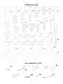
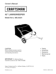
CARTON CONTENTS
1, Grip Assembly
2, Trigger with Cable
3, Left Side Plate
4, Right Side Plate
5, Blade Assembly
6,
7,
8,
Attachment Rod
Handle Guide
Blade Pivot Bracket
9, Trip Spring (2)
10, Lift Link (2)
11_ Skid Shoe (2)
12, Lift Rod
13, Pivot Plate
14, Upper Lift Handle
15, Lower Lift Handle
16,
17,
18,
19,
20,
Lift Bracket
Angle Lock Bar (2)
Frame Assembly
Handle Assembly
Contro! Cable
SHOWN FULL SiZE
I
i-
H
C
B
A
,¢
/
/
3
i
I..........
M
I............ i
--4
/
I........ 3
,.K
i
I.........
i
[........
t
T
...........
/1
/
Q
l.............
I
Z
W
X
/
/
Y
/
I
I
I
I
EE
J
\
\
DD
CC
BB
/
_\\\\
\\\\
\
\
/
FF
\
\
I
/
\
/.f ...........
_
\
\
\,
\
I
\
I
\\\\\\\
\\\\\\_
I
/
/
\\\
NOT SHOWN FULL SmZE
KK
GG
/
JJ
....
LL
/
MM
NN
J
OO
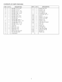
CONTENTS OF PARTS PACKAGE
REFo
QTY.
A
B
C
D
E
F
G
H
I
J
K
L
M
N
O
P
Q
R
S
T
U
2
2
2
2
2
4
2
2
1
6
2
6
1
2
4
4
10
3
1
2
1
DESCRiPTiON
Hex Bolt, 1/2" x 2o3/4"
Hex Bolt, 1/2" x 2"
Hex Bolt, 1/2" x 1ol/2"
Hex Bolt, 5/16" x 1o3/4"
Hex Bolt, 3/8" x 1ol/4"
Hex Bolt, 3/8" x 1"
Hex Bolt, 5/16" x 3/4"
Hex Bolt, 3/8" x 3ol/2
Shoulder Bolt
Carriage Bolt, 3/8" x 1"
Carriage Bolt, 3/8" x 1ol/4"
Carriage Bolt, 5/16" x 1
Hex Bolt, 5/16" x 1ol/2"
Hex Bolt, 1/4" x 1ol/2"
Cotter Pin
Nylock Nut, 1/2"
Ny!ock Nut, 3/8"
Nylock Nut, 1/4"
Whizlock Hex Nut, 3/8"
Hex Jam Nut, 5/16"
Long Spacer
REF.
QTY.
V
W
X
Y
Z
AA
BB
CC
DD
EE
FF
GG
HH
II
JJ
KK
LL
MM
NN
OO
11
4
4
2
4
1
2
6
6
4
4
1
2
2
2
7
2
1
1
1
DESCRiPTiON
Nylock Nut, 5/16"
Hex Nut, 1/2"
Hex Nut, 3/8"
Short Spacer
Lock Washer, 3/8"
Oval Screw, #10 x 1"
Washer
Washer, 1/2" Large
Washer, 5/8" SAE
Washer, 1/2"
Washer, 5/16"
Cable Mount Bracket
Nylon Tie
Clevis Pin
Plastic Cap
Haircotter Pin
Cable End Fitting
Extension Spring
Spring Pin
Plastic Grip
TOOLSREQUIRED
FORASSEMBLY
(1)
(1)
(1)
(1)
(1)
(1)
(1)
,
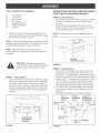
iNSTRUCTiONS
FORTRACTORS WITH SINGLE
FRONT DECK SUSPENSION BRACKET
7/16"Wrench
1/2"Wrench
9/16"Wrench
3/4"Wrench
Adjustable
Wrench
PhillipsScrewd
river
Hammer
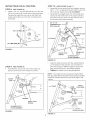
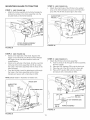
STEP 2: (SEE FIGURE 2)
Remove the tractor hood. Refer to your tractor owners
manual for instructions on how to properly remove
the hood.
,
Remove
a!lpartsandhardwarepackages
fromthe
carton.Layoutpartsandhardware
andidentifyusing
theillustrations
onpages3 and4.
Remove the browning shield from the front of the
tractor as shown. Hold onto the shield as you remove
the second bolt to prevent it from falling.
NOTE: Reinstall the browning shield before using your
tractor.
NOTE: Notallofthesuppliedpartsandhardware
willbe
neededforoneparticulartractor.Unneeded
itemsmaybe
discarded
afterassemblyhasbeencompleted.
NOTE: Righthand(RH)andlefthand(LH)are
determined
fromtheoperator'spositionwhileseatedon
thetractor.
\
\
REMOVE
BROWNUNG
FIGURE 2
untilthetractorengine,
mufflerandexhaust
CAUTION:
Donot beginassembling
deflectorhavebeenallowed
tocooloff.
STEP 3: (SEE FIGURE 3)
,
Fasten the R.H. side plate (bend facing out) to the
front three holes indicated in the tractor frame. Use
three 3/8" x 1" carriage bolts (J) and three 3/8" nylock
nuts (Q). Fasten the rear of the side plate to the frame
using a 5/16" x 1" carriage bolt (L) and a 5/16" ny!ock
nut (V). If there is an engine mounting plate (shown
with dotted lines) that prevents the side plate from
resting flat against the tractor frame, use three large
1/2" washers (CC) as shims between the side plate
and the frame. Tighten all bolts. Repeat for the LH.
side plate.
,
Reinstai! the browning shield removed in figure 2.
STEP 1 : (SEE FIGURE 1)
,
SHUELD
Look under the front of your tractor. If there is a single
mower deck suspension bracket located underneath
the middle of the front axle, continue on to step 2. If
your tractor does not have a mower deck suspension
bracket underneath the middle of the front axle, skip
to step 5 on page 7 for tractors with dua! suspension
brackets.
5/16"
5/16"
ENGmNE
LARGE
CARRmAGE
x t"
MOUNTmNG
WASHER
BOLT
PLATE
(IF
(L)
NYLOCK
--_
NUT (V)
J
/
3/8" NYLOCK
NUT (Q)
"_---_
BRACKET
318" x 1" CARRIAGE
"--_--J"
BOLT
FIGURE 1
FIGURE 3
6
(J)
1/2"
(CO)
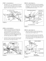
STEP 4: (SEE FIGURE 4)
,
Place a 1/2" washer (EE) and then a short spacer (Y)
onto a 1/2" x 1-1/2" hex bolt (C). Instal! the bolt in the
bottom hole at the front of the R. H. side plate and secure
it with a 1/2" nylock nut (P). Repeat for the L.H. side
plate,
Skip to step 8 on page 8.
STEP 6: (SEE FIGURE 6)
,
Fasten the R.H. side plate (bend facing out) to the two
holes indicated in the tractor frame. Use two 3/8" x 1"
hex bolts (F) and 3/8" lock washers (Z). If the bolts
insert loosely into the tractor frame, use two 3/8" nylock
nuts (Q) on the inside of the frame. Repeat for the LH.
side.
3/8" NYLOCK NUT (Q)
(IF NEEDED)
1/2" X 1ol/2"
HEX BOLT (C)
\
3/8" x 1"
\
h
\
"\
HEX BOLT (F)
_j
SPACER (Y)
1/2" WASHER (EE)
1/2" NYLOCK
NUT (P)
FIGURE 4
FIGURE 6
iNSTRUCTiONS
FOR TRACTORS WITH
FRONT DECK SUSPENSION BRACKETS
STEP 7: (SEE FIGURE 7)
,
Place a 1/2" washer (EE) and then a short spacer (Y)
onto a 1/2" x 1-1/2" hex bolt (C). Install the bolt in the
bottom hole at the front of the R.H. side plate and secure
it with a 1/2" nylock nut (P). Repeat for the LH. side
plate.
Go to step 8 on page 8.
DUAL
STEP 5: (SEE FIGURE 5)
,
Remove bolts from holes shown in illustration if they
are present.
REMOVE
FROM
BOLTS
THESE
HOLES
HEX BOLT (C)
SPACER (Y)
1/2" NYLOCK
1/2" WASHER (EE)
X\
FRONT
SUSPENSmON
BRACKET
\
FIGURE 5
FIGURE 7
NUT (P)
iNSTRUCTiONS
FOR ALL TRACTORS
STEP 10: (SEE FIGURE 10 and 11)
STEP 8: (SEE FIGURE 8)
',
Install a 1/2" x 2" hex bolt (B) and two 1/2" hex nuts
(W) in the outer hole in each side of the pivot plate.
Temporarily adjust the hex nuts so that both bolt
heads extend about an inch and a half above the
pivot plate.
',
Assemble the two angle lock bars together using a
3/8" x 1ol/4" carriage bolt (E) and a 3/8" nylock nut
(Q) in the top square hole& Do not tighten.
',
Assemble the straight hook end of the angle lock
spring into the small holes in the angle lock bars.
Insert the lock bars down into the lock bar slot in
the channel pivot plate assembly.
3/8" X 1ol/4"
CARRIAGE BOLT
(TOP HOLE) (E)
\
3/8" NYLOCK
1/2" X 2" BOLT (B)
ANGLELOCK
)
FRONT
,©
"o
112" HE× NUTS (W)' _
io
c
LOCKBAR
SLOT
FIGURE 8
ANGLE LOCK
SPR_NG
SPRRNG
P_N
HOLE
CHANNEL/PIVOT
PLATE
ASSEMBLY
FIGURE 10
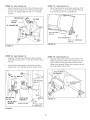
STEP
,,
9:
Align the angle lock bars with the welded bracket
on the bottom of the channel, Use a hammer to
drive the spring pin (NN) through the angle lock
bars and into the slot in the welded bracket.
Tighten the nylock nut on the carriage bolt.
(SEE FIGURE 9)
Assemble the round hook end of the angle lock
spring into the hole in the washer as shown,
NOTE: The angle lock bars should pivot freely, When
they are pulled all the way back the pivot plate assembly
should be unlocked and free to pivot to the right or left
notches.
-_,_FRONT
ANGLE
LOCK BARS
Q
G
@
WASHER
ANGLELOCK
SPRmNG
LOCK
BARS
CHANNEUPIVOT
PLATE ASSEMBLY
1/4"' X l"'
SPRING PIN (NN}
FIGURE 9
FIGURE 11
8
STEP 11: (SEE FIGURE 12)
o
Assemble a 3/8" x 1ol/4" carriage bolt (E) through
the cable mount bracket (GG) and then mount it
from the left side to the square holes in the angle
lock bars, Secure the bracket at the angle shown in
figure 14 with a 3/8" nylock nut (Q).
STEP 13: (SEE FIGURE 14)
Attach the cable end fitting (LL) and the long spacer
(U) to the left hand hole in the channel and lift bracket
using a 1/4" x 1ol/2" hex bolt (N) and 1/4" nylock nut
(R)=Tighten, keeping the cable end fitting aligned
with the threaded end of the cable.
CABLE MOUNT BRACKET
3/8" NYLOCK NUT (Q)
_
LOCK-_._I
_
I /
/,
BRACKET
1/4" X 1-1/2"
HEX BOLT (N)
CABLE
END
FiTTiNG
(ll)
LONG
(GG)
SPACER(U)
CHANNEL
O
cKET
FIGURE 12
1/4" NYLOCK NUT (R)
FIGURE 14
STEP 12: (SEE FIGURE 13)
Select the control cable with two threaded ends,
Select the threaded end that has no rubber cap
or nuts and assemble a 5/16" hex jam nut (T)
approximately 3/4" onto the threads, Insert the
threaded end of the cable through the round hole
in the cable mount bracket (GG) and secure it with
another 5/16" hex jam nut (T). Tighten the second
nut while keeping the first nut in place.
Assemble the ball end of the cable wire up through
the hole in a cable end fitting (LL) and then slide it
back inside the curled edge of the fitting.
STEP
14:
(SEE FIGURE 15)
Attach the lift bracket to the right hand hole in the
channel, next to the long spacer, Use a 5/16" x 3/4"
hex bolt (G) and 5/16" nylock nut (V).
Attach the frame assembly to the channel assembly.
Fit one side of the frame assembly onto the 3/4" rod
of the channel and then fit the other side onto the rod.
Secure each side with a 3/4" washer (BB) and a 1/8"
x 1ol/4" cotter pin (O).
ASSEMBLY
FRAME
5/16" X 3/4" BOLT (G)
LIFT BRACKET
]
BALL END
ROD
5/16" BEX
(T)
5116" NYLOCK
NUT (V)
FIGURE 13
FIGURE 15
314"WASHER (BB)
118" x 1-114"
COTTER PIN (O)
STEP 15: (SEE FIGURE 16)
,
STEP 17: (SEE FIGURE 18)
,
Attach the skid shoes to the blade using four 5/18"
x 1" carriage bolts (L), 5/18" fiat washers (FF) and
5/18" nylock nuts (V), Do not tighten yet,
Attach the ends of the lift rod to the lift bracket on the
channel and the welded arm on the frame assembly.
Use two 1/2" washers (EE) and 1/8" x 1ol/4" cotter
pins (O).
WELDED ARM
LIFT ROD
COTTER
PIN (0)
_!
112" WASHER (EE)
1
5116" x 1" CARRIAGE
BOLT (L)
FIGURE 18
FIGURE 16
STEP 18: (SEE FIGURE 17)
,
STEP 18:
Assemble the blade pivot bracket to the pivot plate
assembly using two 3/8" x 1" bolts (F) and 3/8" nylock
nuts (Q),
,
Assemble the handle guide to the frame assembly
using a 5/16" x 3/4" bolt (G) and 5/16" ny!ock nut (V),
3/8" NYLOOK
/
NUT (Q)
/
BLADE PIVOT
BRACKET
PIVOT PLATE
ASSEMBLY
HANDLE
GUIDE
FIGURE 19
5116" X 3/4"
BOLT (G)
FIGURE 17
10
(SEE FIGURE 19}
Align the channel pivot plate assembly behind the
blade and guide the ends of the mounting rod, one
end at a time, into the holes at the bottom of the
blade mount gussets. Secure the mounting rod with
two large hairpin cotters (KK).
STEP 19: (SEE FIGURE 20)
,
STEP 21: (SEE FIGURE 22)
Slide the handle assembly through the handle guide
so that the flattened end rests on the blade pivot
bracket,
insert each 3/8" x 3ol/2" hex bolt (H) into a blade trip
spring.
Assemble a 3/8" hex nut (X) onto the end of each 3/8"
x 3-1/2" hex bolt (H) leaving the nut about 2" from the
end of the bolt.
Secure the end of the handle to the top side of the
blade pivot bracket with the shoulder bolt (I) on top
and a 3/8" hex whiz!ock nut (S) underneath.
3/8" HEX NUT (X)
Secure cable to handle tube with a plastic tie (HH)
near bottom of handle. Cut off extra plastic on end.
CONTROL
CABLE
3/8" X 3-1/2"
HEX BOLT (H)
BLADE
TRmP SPRING
TIE (HH)
\
FIGURE 20
3/8"HEX
NUT (S)
/
STEP 20: (SEE FIGURE 21)
,
Hook the spring assemblies into the spring mount
ears on the pivot plate, Insert the end of each bolt
up through the hobs in the top of the blade and
assemble a 3/8" hex nut (X) onto each trip spring,
Tighten both nuts on each bolt so that approximately
1" of the bolt extends through the top of the blade,
FIGURE
Assemble the plastic caps (JJ) onto the bolts.
PIVOT
BRACKET
HANDLE
TUBE
22
STEP 22:
,
Adjust the stop bolts in the pivot plate so that the
bolts extend equally 1ol/2" above the pivot plate,
creating tension on the spring assemblies.
HEX
BLADE
(SEE FIGURE 23)
Remove the rubber cap and the first jam nut from
the threaded end of the control cable and slide them
onto the control cable wire, Adjust the second jam nut
on the threads so that it is approximately 3/4" from
end, Assemble threaded end of cable through the
cable mount ear and secure it with the first jam nut,
Reinstall the rubber cap onto the threaded cable end,
HANDLE
ASS'Y.
NUT (X)
HANDLE
GUIDE
BOLT
_PRmNG
MOUNT EAR
FIGURE
21
FIGURE
11
23
STEP 23:
(SEE FIGURE 24)
STEP 25: (SEE FIGURE 26)
o Attach the lower lift handle to the right side of the
frame assembly using two 5/16" x 1o3/4" hex bolts (D)
and 5/16" nylock nuts (V),
Assemble grip (OO) to grip assembly.
Assemble grip assembly to handle assembly using a
5/16" x 1-1/2" hex bolt (M) and 5/16" nylock nut (V).
Assemble the ball end of the cable wire (shown in
figure 23) up through the hole in a cable end fitting
(LL) and then slide it back inside the curled edge of
the fitting.
Assemble cable end fitting (LL) over 1/4" weld bolt on
grip assembly and secure with one 1/4" nylock nut (R)
and then back nut off 1/2 turn.
LmFT HANDLE
NOTE: Do not over tighten 1/4" nylock nut, cable end
fitting must pivot freely.
5116" NYLOCK
-"_'_'-@ .....
'
NUT (V)
1/4" WELD DOLT
5/16"
X 1-3/4"
HEX DOLT
GRmP ASSEMBLY
CABLE END
FreTTING (LL)
GRmP (OO)
1/4" NYLOCK
k_
FIGURE
BRACKET
26
NUT (R)
HANDLE
ASSEMBLY
LIFT
(D)
STEP 26: (SEE FIGURE 27)
Insta!l the trigger assembly to the lift handle using an
oval screw (AA).
Connect the hooked end of the cable wire into the
index lift rod. Insta!l the threaded end of the cable into
the notch in the top of the lift bracket, ptacing one jam
nut on each side of the notch with the lock washer
below the notch.
5/16" NYLOCK
NUT (V)
5/16" X 1ol/2"
HEX BOLT (M)
CABLE
FIGURE 24
Adjust the jam nuts so that when the trigger on the lift
handle is squeezed, the bottom of the index lift rod
raises enough to release from the latched position.
The index lift rod should also lower far enough to lock
in the latched position when the trigger is released.
Secure cable to handle with a plastic tie (HH) to
prevent cable from interfering with tractor. Cut off
extra plastic on end of tie.
STEP 24: (SEE FIGURE 25)
,
Assemble the upper lift handle onto the lower lift
handle and fasten using a 1/4" x 1-1/2" bolt (N) and
1/4" nylock nut (R),
OVAL ii...._%
SCR "_/
]
LUFTRELEASE
CABLE
1/4" x 1ol/2"
BOLT (N)
TRIGGED
.E×NOT
ASSEMDL¥
--
L°cK
I -.b,WADHEB
NUT (D)
l
([4
......
FIGURE 25
FIGURE 27
12
UNDEX
I
-"_""'_
UFT
ROD
MOUNTING
BLADE TO TRACTOR
STEP 3: (SEE FIGURE 30)
,
STEP 1 : (SEE FIGURE 28}
,
Attach the frame assembly to the frame brackets by
sliding the notches in the frame assembly onto the
shouJder boJts on the frame brackets.
Attach the small holes of the Jift Jinks to the weJded
pins on the frame bracket and secure with haircotter
pins (KK), The lift link should angle to the inside,
HA{RCOTTER
PmN
(KK)
L9
LUFTLiNK
ATTACH FRA[tvIE ASSEMBLY
TO SHOULDER
BOLTS
FIGURE 30
FIGURE 28
STEP 2: (SEE FIGURE 29)
,
,
,
Stand on the right side of the blade. Squeeze the
trigger on the lift handle and Jiftthe handle. Release
the trigger, but do not al!ow handle to lower into
locked position.
Stand on the left side of the blade. Grip the round bar
at the top of the frame assembly and lift up to align
the hoJes in the frame assembly with the holes in the
frame brackets.
From the left side, insert the attachment rod through
the holes in the frame assembly and the frame
brackets and secure with a haircotter pin (KK).
STEP 4: (SEE FIGURE 31)
,
Attach the lift Jinks to the frame assembly:
A. Insert a clevis pin (ll) through the frame assembly
from the outside.
B.
C.
D.
Place two 5/8" washers (DD) onto the clevis pin.
PJace the end of the lift tink onto the cJevis pin.
Place a 5/8" washer (DD) onto the clevis pin
and secure with a haircotter pin (KK).
NOTE: Blade hidden in illustration for better view.
ROUND
BAR
HAIROOTTER
PIN (KK)
LiFT
LiFT LmNK
HAIRCOTTER
CLEVUS
PiN (m0
FIGURE 31
FIGURE 29
13
FRAME
ASSEMBLY
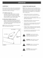
CONTROLS
USING "['HE DOZER BLADE
Become familiar with all of the controls and adjustments
on the tractor and dozer blade before operating. Refer to
tractor owners manual for tractor controls. Controls for
operating dozer blade are as follows:
NOTE: Wheel weights and tire chains should be used
with your dozer to improve traction. For additional traction,
install wheel weight on rear of draw bar using a weight
bracket kit and one wheel weight from a wheel weight kit.
These accessories are available at your nearest Sears
retail or catalog sales.
LmFT HANDLE: (Figure 32)
Located on right hand side of tractor. To raise the
dozer blade, push the lift handle down until blade
locks in the up position. To lower the dozer blade,
push down slightly on the lift handle, depress trigger
and then lift up on handle to lower the blade.
Prepare the tractor engine for cold weather by
following the instructions furnished with the tractor.
Inspect the area to be worked carefully before
operating the dozer blade. Avoid pipes, roots, curbs or
other heavy obstructions.
BLADE ANGLE HANDLE: (Figure 32)
Located on the left hand side of tractor. When dozer
blade is in the up position, depress grip assembly
and push or pul! on handle to swivel blade to the right
or left. Release grip assembly to lock the blade in the
left, center or right position.
Always begin transmission in first (low) gear and
gradually increase speed as required.
Operate tractor at reduced speed when dozer blade
trip springs are locked out. Refer to Service and
Adjustment section.
NOTE: Always raise dozer blade and lock in up position
before moving blade angle handle.
GRiP
,
If blade is stored in heated area, allow tractor blade
to adjust to outdoor temperature before operating to
reduce icing on the metal surfaces.
,
For improved show removal performance, coat the
blade with automotive type paste wax.
ASSEMBLY
LtFT
LIFT HANDLE
TRIGGER
BLADE
CAUTION: Know the terrain, Avoid
exceptionally sharp slopes or drop-offs
which may be hidden by the snow,
ANGLE
HANDLE
WARNING:
Hidden objects can cause
sudden stops or change in direction
WARNING:
FIGURE
32
Never run the dozer blade
into heavy material at high speed.
CAUTION: Always tower blade to
ground before leaving tractor
14
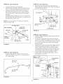
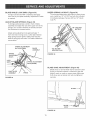
BLADE ANGLE LOCK BARS: (Figure 33)
if angle lock bars DO NOT completely disengage
from slots in pivot plate assembly, adjustment of cable
is required,
DOZER SPRING LOCKOUT: (Figure 34)
To lock dozer blade spring trip action for heavy dozer
work, }nsta!l two 1/2" x 2o3/4" hex bolts (A) (included
in hardware package,) Secure with two 1/2" nylock
nuts (P).
ADJUST BLADE SPRINGS: (Figure 33)
To change spring tension, stand in front of blade
assembly and adjust the nuts at the upper end of the
springs= Turn counter clockwise to decrease tension
and clockwise to increase tension=
!/2"
NYLOOK
NUTS(P)
Adjust spring adjustment nuts approximately 1"
from end when moving snow or other light material,
Keep spring tension light for safety, This frees the
blade to spring trip and return if a hidden obstacle is
encountered.
SPRmNG ADJUSTMENT
NUTS
BLADE
(OUTSIDE)
1[2" X 2_314"
HEX BOLTS (A)
ASSEMBLY
SPRUNG
FIGURE 34
ADJUSTMENT
BOLTS
LOCK
BARS
SPRING
ADJUSTMENT
NUTS (INSRDE)
PIVOT PLATE
ASSEMBLY
FIGURE
BLADE SHOE ADJUSTMENT:
(Figure 35)
Blade shoes on end of blade may be raised for clean
dozing on smooth surfaces or lowered to raise the
blade to work on rough or uneven areas, Make sure
both shoes are set evenly and nuts are tightened
securely
CABLE
33
FIGURE 35
15
CUSTOMER
,
RESPONSIBtLmTIE$
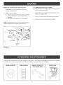
Read and follow the maintenance schedule and the maintenance procedures listed in this section,
MAINTENANCE
SCHEDULE
//__/',,_//_
Fill in dates
as you
complete
regular
service.
__/_
Check for loose fasteners
X
Check scraper and shoes for wear
Clean Blade
Lubricate Blade
_x_"
Service Dates
_ X .................
X
X
X
CHECK FOR LOOSE FASTENERS
,
During the operating season, check al! bolts, nuts and
hairpin cotters to be sure they are secure.
BLADE
ASSEMBLY
CHECK SCRAPER AND SHOES FOR WEAR
,
During the operating season, check the scraper and
shoes for wear before each use. After extensive use
and wear, the scraper bar may be reversed to utilize
the unused top edge. See figure 36.
CLEAN BLADE
•
During the operating season, clean the blade off after
each use. Touch up any bare metal with paint or
apply a light coat of grease or rust preventive.
SCRAPER
BAR
LUBRICATE BLADE
Oil al! pivot points each season so they will work
freely.
PROBLEM
Blade is difficult to raise.
Blade is difficult to pivot.
Blade will not unlock to pivot.
FIGURE
CABRtAGEBO_S
AND NUTS
36
CAUSE
CORRECTION
Lift mechanism is binding.
Lubricate pivot points.
Handle tube is binding on lift rod.
Lubricate lift handle rod.
Lock mechanism is out of adjustment
and is not disengaging.
Refer to the Operation section on
page 14.
16
REMOVING DOZER BLADE FROM TRACTOR
RECOMMENDATIONS WHEN STORING
When the dozer is not being used, remove all dirt and
rust and touch up with paint.
1_ Lower blade to ground with blade in the center
(straight ahead) position.
,
Apply a light coat of grease or rust prevention to the
blade and oil pivot points.
Refer to figure 37 below:
A, Remove cotter pins and lift links from side plates,
B, Remove attachment rod from blade frame
assembly,
C, Pull blade frame assembly from side plates,
,
Store in an area where it is protected from weather.
,
Store in a dry area, protected from weather.
NOTE: Frame brackets do not require removal unless a
different attachment is mounted to front of tractor,
ATTACHMENT
COTTER
,
\
\
\
UFT LmNK
CLEVmS
PIN
FIGURE 37
These and other accessories are recommended for use with your unit, Call 1-800-4-MyoHOME®to find out if they are available,
if available, they may be purchased at most Craftsman outlets or by calling I°800°4-MyoHOME®,
TIRE CHAUNS
WEIGHT BRACKET
FOR DRAW BAR
17
SNOW CAB
/
1
m
l
20
73_
19_
86
71
\
_._
\
\
21
/
A
"50
7
89
70
/
24
'33
©
26
/
©
22
m
Rim
76
49
49
23
49
\e.
55
5
l
\
©
N
m
r
m
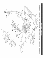
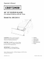
REPAIR PARTS FOR MODEL 486.24414RER
NO.
1
2
3
4
5
6
7
8
9
10
11
12
14
15
16
17
18
19
2O
21
22
23
24
25
26
27
28
29
3O
31
32
33
34
35
36
37
38
39
4O
41
42
43
44
45
46
PART NO.
65379
25701
44326
43682
47810
23639
R3132J
62556
65358
710-0741
1540-162
40436
40598
49264
49265
47674
49912
7071
65348
49808
65359
24312
741-0192
43093
43601
47368
47369
63773
732-0306
IR19131316
142
48049
43063
43840
43064
43086
25666
65436
65403
65402
49819
47066
726-0178
746-0260
43343
QTY.
1
2
12
2
19
1
2
1
1
1
2
1
1
1
1
1
1
1
1
1
1
2
2
1
1
1
1
1
1
3
1
1
2
2
4
4
1
1
1
1
1
1
2
2
7
RER
NO.
DESCRIPTION
48" Blade Ass'y.
Skid Shoe Bracket
Carriage Bolt, 5/16-18 x 1"
Carriage Bolt, 5/16-18 x 1-1/4"
Ny!ock Hex Nut, 5/16"
Wear Plate 48"
Skid Shoe
Pivot Plate Ass'y.
Channel Ass'y.
Hex Bolt 3/4-10 x 3=1/2"
Washer 3/4"
Hex Jam Nut, 3/4-10
Hex Lock Nut, 3/4-10
Lift Handle Tube (Lower)
Lift Handle Tube (Upper)
Tube Plug
Trigger & Lift Cable Ass'y.
Handle Grip
Handle Ass'y.
Control Cable
Lift Ass'y.
Mounting Bracket
Flange Bearing (w/Fiats)
Cotter Pin, 1/8 x1-1/2"
Washer, 1.59" x 1.032" x 0.60"
Spring Pin, 5/16" x 1-3/4"
Spring Pin, 3/16" x 1-3/4"
Bracket Handle Lift Ass'y.
Compression Spring
Washer, 3/8" x 13/16" x 1/16"
Cotter Pin, 1/8" x 3/4"
Index Lift Rod
Hex Bolt, 5/16" x 1"
Hex Bolt, 5/16" x 1-1/4"
Hex Lock Nut, 5/16"
Lock Washer, 5/16"
Spacer Bracket
Tube Guide Bracket Ass'y.
Side Plate (Left Hand)
Side Plate (Right Hand)
Lift Rod
Attachment Rod
Nylon Tie
Cable End Fitting
Haircotter Pin, 3/32" x 2-5/16"
19
47
48
49
50
51
52
53
54
55
56
57
58
59
60
61
62
63
64
65
66
67
68
69
70
71
72
73
74
75
76
77
78
79
80
81
82
83
84
85
86
87
88
89
48" DOZER BLADE
PART NO.
QTY.
43510
710-0305
HA21362
47189
43001
712-0256
41596
712-0206
711-0309
R19212113
R19172410
43087
43081
43648
49266
47364
43020
712-3083
R19171616
25688
43003
43349
05762
43348
48106
23658
43085
43084
43182
43010
44072
43350
43009
24298
25725
R9466R
44071
43015
44074
62561
23151
23646
731-0869
49810
2
2
10
3
4
2
2
4
2
6
6
2
6
2
1
2
2
4
4
1
4
1
1
1
1
1
1
2
2
4
1
6
2
1
2
2
2
4
2
1
2
1
1
1
DESCRIPTION
Hex Bolt, 1/2" x 2=3/4"
Carriage Bolt, 3/8" x 1-1/4"
Nylock Hex Nut, 3/8"
Nylock Hex Nut, 1/4"
Hex Bolt, 3/8" x 1"
Hex Jam Nut, 5/16"
Hex Bolt, 1/2" x 2"
Hex Nut, 1/2"
Clevis Pin, 5/8" x 1.2"
Washer, 5/8" SAE
Washer, 1/2" x 1-1/2"
Hex Bolt, 3/8" x 1=1/4"
Washer, 5/16"
Hex Bolt, 1/4" x 1=1/2"
Oval Screw, #10 x 1"
Spacer, .52" x .75" x .4"
Hex Bolt, 1/2" x 1=1/2"
Nylock Nut, 1/2"
Washer, 1/2" x 1" (Small)
Lift Rod Bracket
Lock Washer, 3/8"
Spring Pin, 1/4" x 1"
Cable Mount Bracket
Extension Spring
Shoulder Bolt
Spacer, .39" x .56" x .62"
Hex Bolt, 5/16" x 1-1/2"
Hex Bolt, 5/16" x 1-3/4"
Hex Bolt, 5/16" x 3/4"
Cotter Pin, 1/8" x 1=1/4"
Whizlock Hex Nut, 3/8"
Carriage Bolt, 3/8" x 1"
Washer, 3/4"
Lift Bracket
Lift Link
Trip Spring
Hex Bolt, 3/8" x 3=1/2"
Hex Nut, 3/8"
Plastic Cap
Release Grip Ass'y.
Angle Lock Bar (Short)
Blade Pivot Bracket
Plastic Grip
Owners Manual
iiiiiiiiiiiiiiiii
iiiiiiiiiiiiiiiiii
For repair-in
your home-of
all major brand appliances,
lawn and garden equipment, or heating and cooling systems,
no matter who made it, no matter who sold it!
:::::::::::::::::
iiiiiiiiiiiiiiiiii
For the replacement
parts, accessories
and
owner's manuals that you need to do-it-yourself.
:::::::::::::::::
iiiiiiiiiiHHHH
For Sears professional
installation
of home appliances
and items like garage door openers and water heaters.
1-800-4-MY-H O ME® (1-800-469-4663)
www.seors.°o
www.sears.°o
Our Home
For repair of carry-in items like vacuums, lawn equipment,
and electronics, call or go on-line for the location of your nearest
Sears Parts & Repair Center.
1-800-488-1222
...................
...................
CCC::
CCC::
Call anytime,
day or night (U.S.A. only)
www.sears.com
To purchase a protection agreement (U.S.A.)
or maintenance agreement (Canada)on a product serviced
1-800-827-6655
(U.S.A.)
1-800-361-6665
Pard pedir servicio de reparaciOn
® Registered
(Canada)
en frangais:
1-888-SU-HOGAR®
1.800.LE.FOYERMC
(1-800-533-6937)
(1-888-784-6427)
www.sears.ca
a domicilio,
:::::::::::::::::ii
Au Canada pour service
by Sears:
Trademark
y pard ordenar
/ TM Trademark
piezas:
/ SM Service
Mark of Sears
Brands,
® Marca Registrada / TMMama de F_brica / SMMarca de Servicio de Sears
Mc Marque de commerce / MD Marque dCpos_e de Sears Brands, LLC
!!!!!!!!!!!!!!!!ii!i
LLC
Brands,
LLC
® Sears Brands, LLC