1
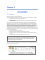
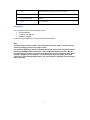
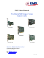
EMS User Manual
The XtremeRGB Range of Video
Capture Cards
XtremeRGB-Ex1
XtremeRGB-Ex2
XtremeRGB-II
XtremeRGB-Ex4+
XtremeRGB-Ex8
Electronic Modular Solutions Limited
Kendal House, 20 Blaby Road, S. Wigston,
Leics., LE18 4SB, England
Tel: +44 (0) 116 2775730
Fax: +44 (0) 116 2774973
Email: [email protected]
Web: www.ems-imaging.com
10 Nov 2009
Contents
Chapter 1
Safety Instructions ................................................................................................................................ 3
Chapter 2
Introduction .......................................................................................................................................... 4
Chapter 3
XtremeRGB-Ex1................................................................................................................................... 5
Chapter 4
XtremeRGB-Ex2................................................................................................................................. 14
Chapter 5
XtremeRGB-II ..................................................................................................................................... 22
Chapter 6
XtremeRGB-Ex8................................................................................................................................. 32
Chapter 7
XtremeRGB-Ex4+ .............................................................................................................................. 40
Chapter 8
EMS Limited ....................................................................................................................................... 51
Chapter 9
Index .................................................................................................................................................. 53 Chapter 1
Safety Instructions
To prevent damage to your EMS product or injury to personnel operating the equipment, please read
the following safety precautions prior to operation. These instructions should be made available to all
those who will use and operate EMS products.
Power Supply
All EMS products require a mains power supply. This power supply must be disconnected when
equipment is being upgraded or relocated.
Cables
Do not expose cables to any liquids; doing so may cause a short circuit which could damage the
equipment. Do not place heavy objects on top of any cables as this can cause damage and possibly
lead to exposed live wires.
Ventilation
All computer equipment should be located in a well ventilated area. All ventilation holes on the
computer casing must be kept clear of any obstruction at all times. Failure to do so will result in the
system over heating and damaging your equipment.
Working Environment
The equipment should be located in an environment free from dust, moisture and extreme changes in
temperature and should be placed on a stable and solid work surface. Liquids (hot/cold drinks etc)
should not be placed near the equipment as spillage could cause serious damage.
Gas/Flammable Liquids
Electronic equipment should never be used in the presence of gas or any flammable liquid, doing so
could result in an explosion or serious fire.
Smoke/Unusual Smells
Should you notice smoke or unusual smells being emitted from your computer, turn off and unplug the
system from the mains supply. The system should then be passed to a qualified technician for
inspection. Continued operation could result in personal injury and damage to property.
Maintenance
Maintenance should only be carried out by competent technicians, any EMS plug-in cards that are
physically damaged should be returned to EMS for repair using EMS RMA procedures.
Disposal
At the end of life all EMS products should be disposed of as per local laws and regulations dictate. In
UK contact EMS to arrange disposal. Our WEE registration number is WEE/AA0005ZR.
Chapter 2
Introduction
The EMS XtremeRGB range of video capture cards HD, HDMI, VGA/ RGB or DVI video sources in
real time enabling you to view data from PCs, MACs, industrial / medical equipment, cameras and
other video equipment. The XtremeRGB-Ex8 and XtremeRGB-Ex4+ captures PAL, SECAM and
NTSC in both composite and S-Video.
The Windows® software provided with the cards allows the signal to be captured and displayed on
your desktop or recorded and saved to your hard drive.
Windows Media Encoder® may also be used to stream video across a network or save the video to
disk. Windows Media Player® can be used to display the stream or the video that has previously been
saved.
Using our SDK, you can produce or customise your own application programs.
Chapter 3
XtremeRGB-Ex1
FCC Compliance XtremeRGB-Ex1
Federal Communications Commission Statement
This device complies with FCC Rules Part 15. Operation is subject to the following two conditions:
•
This device may not cause harmful interference, and
•
This device must accept any interference received, including interference that may cause
undesired operation
This equipment has been tested and found to comply with the limits for a Class B digital device,
pursuant to Part 15 of the FCC Rules. These limits are designed to provide reasonable protection
against harmful interference in a commercial, industrial or business environment. This equipment
generates, uses and can radiate radio frequency energy and, if not installed and used in accordance
with the manufacturers instructions, may cause harmful interference to radio communications.
However, there is no guarantee that interference will not occur in a particular installation. If this
equipment does cause harmful interference to radio or television reception, which can be determined
by turning the equipment off and on, the user is encouraged to try to correct the interference by one or
more of the following measures:
•
Re-orient or relocate the receiving antenna
•
Increase the separation between the equipment and the receiver
•
Connect the equipment to an outlet on a circuit different from that to which the receiver is
connected
•
Consult the dealer or an experienced radio/TV technician for help
Warning! Any changes or modifications to this product not expressly approved by
the manufacturer could void any assurances of safety or performance and could
result in violation of Part 15 of the FCC Rules.
Reprinted from the Code of Federal Regulations #47, part 15.193.1993. Washington DC: Office of the Federal Register, National Archives and
Records Administration, US Government Printing Office.
DECLARATION OF CONFORMITY
Per FCC Part 2 Section 2. 1077(a)
Responsible Party Name:
EMS Limited
Address:
Leicester, England
Phone:
+44116-2775730
Hereby declares the product:
Product Name:
RGB Video Capture PCIe Card
Model Number:
XtremeRGB-Ex1
Conforms to the following specifications:
FCC Part 15 Subpart b
Class A Digital Device
Supplementary Information:
This device has been shown to be in compliance with and was tested in accordance with
the measurement procedures specified in the Standards & Specifications listed above and
as indicated in the measurement report number: 7G0507GUS3
Representative Persons Name: Tony Jones, Operations Director
Signature:
Date: 22 May 2008
Introduction – XtremeRGB-Ex1
The XtremeRGB-Ex1 a single channel PCIe capture card can capture:
•
Component HD up to 1080P at 60 frames per second (Requires optional Component HD-DVI adapter)
•
HDMI up to 1080P (Requires optional Component HD-DVI adapter, Audio not supported, HDCP not supported)
•
DVI up to 1920 x 1200
•
RGB/VGA up to 2048 x 1536
The data is stored in a 32MB frame buffer on the card in real time. The data is transferred using PCI
bus master DMA with scatter gather.
The data can be transferred to system memory or to off-screen memory on a EMS graphics card.
Models
XtremeRGB-Ex1 - A single channel PCIe x4 low profile capture card.
Specification
•
Board Format
PCIe x4 low profile card, 68.9mm x 167.6mm
PCIe bus master with scatter gather DMA providing maximum data rate of
480MB/s
•
Connectors
One DVI-I Type connector
•
Maximum Sample Rate:
170 Mpixels per second analog RGB or 165MHz DVI
•
Video Sampling:
Analog RGB: 24 bits per pixel / 8-8-8 format
•
Video Capture Memory:
32MB per channel (updated in real time). Triple buffered
•
Analog RGB Mode Support:
640 x 480, 800 x 600, 1024 x 768, 1280 x 1024, 1600 x 1200, 1920 x 1080,
2048 x 1536, Custom modes
•
DVI Single Link Mode Support:
640 x 480, 800 x 600, 1024 x 768, 1280 x 1024, 1600 x 1200, 1920 x 1080,
1920 x 1200 and Custom modes
•
HD Modes
1080p, 1080i, 720p, 567p, 480p and 480i using a Component HD connector
(HDCP not supported)
•
Input Mode Detection:
Automatic detection of input modes in hardware enabling the tracking of mode
changes in the source signal
•
Pixel Transfer Formats:
RGB: 5-5-5, 5-6-5 or 8-8-8 pixels
YUV 4:2:2 modes: UYVY, YUY2 or YVYU
MONO: 8bit
•
Update Rate:
User defined, captured frame rate will match the source providing max data
rate (480MB/s) is not exceeded.
Triple buffered to eliminate tearing artifacts
•
Video Format Options:
Analog RGB plus HSync and VSync (5 wire)
Analog RGB with Composite Sync (4 wire)
Analog RGB with Sync on Green (3 wire)
DVI Single Link
•
Operating System Support
Windows® XP, Windows® Vista, Windows® Server 2003, Windows® Server
2008 and Windows® 7 (x86 and x64 Operating Systems)
•
Power Requirements
Max current at +3.3V – 0.25A
Max current at +12V – 0.5A
Max power – 6.8 Watts
•
Operating Temperature:
0 to 35 deg C
•
Storage Temperature:
-20 to 70 deg C.
•
Relative Humidity
5% to 90% non-condensing
•
Analog Input Range:
Min 0.5Vpp
•
Input Offset:
+/-2V
•
Hsync:
15kHz - 110kHz
•
Vsync:
No hardware limits, typically 25Hz - 200Hz for real signals
Max 1.0Vpp
•
Separate Sync Polarity:
Positive or Negative. (Separate H & V sync, Composite Sync)
•
Sync On Green Polarity:
Negative
•
Inputs:
75 Ohm terminated
Unpacking
Your packing box should contain the following items:
•
•
•
1 x DVI to VGA Adapter
1 x low profile card bracket
Installation CD ROM
If there are any discrepancies, you should contact EMS immediately.
Note:
All plug-in cards are static sensitive and are packed in anti-static material. Please keep the
card in its packaging until you are ready to install.
It is recommended that you do not discard the packing box until you are completely satisfied
with the XtremeRGB-Ex1 capture card and it is fully installed and working correctly. We also
recommend that you make a note of the serial number of the card in a prominent place before
the card is plugged into the computer. This should hasten any query should you need to
contact our Technical Support Department. The serial number is displayed on the card itself
and the box label.
Installing the Capture Card
You are likely to need a flat blade and a Phillips head screwdriver for the installation of the capture
card; it would be useful to have these to hand before you begin.
Installing the card is a simple process, follow the steps below to be up and running in a few minutes:
•
Power down the PC (including peripherals), switch off at the mains and disconnect all the
cables connected to the computer, noting the positions for accurate reconnection. Remove
the PC cover
•
Locate a vacant PCIe (x4 or above) slot for the XtremeRGB-Ex1 on the motherboard and
remove the backing plate (retain all screws). If in doubt consult your motherboard
documentation to correctly identify a PCIe (PCI-express) slot. If the card is forced into
a 32 or 64 bit PCI or PCI-X slot it will be irreparably damaged when the system is
powered up and the warranty will be void.
•
Remove the card from its packaging and secure it firmly into the empty PCIe slot. Extreme
care should be taken when securing the card into the slot as some motherboards may
have components that impede the siting of the card
•
Screw the card bracket to the back panel of the PC and replace the cover
•
Re-connect all cables to the PC
•
Connect the cable(s) distributing the RGB/DVI signals to the connectors on the XtremeRGB
card located on the back panel.
•
Power up the PC and commence the software installation.
Connections
The XtremeRGB-Ex1 has one DVI-I type connector.
The card is connected using:
•
DVI-D Cable
•
DVI-A Cable
•
Analog VGA (RGB) cable (adapter supplied)
•
HDMI cable (adapter supplied as optional)
•
Component HD cable (adapter supplied as optional)
Connect one end of the cable to the source. Connect the other end of the cable to DVI-I type
connector located on the XtremeRGB-Ex1 card in your computer.
DVI to VGA adapters are supplied for use with an analog VGA (RGB) Cable.
Installing Multiple Cards
Up to 32 cards can be installed in a system providing a maximum of 32 capture channels.
Combinations of all XtremeRGB capture cards in the same machine are supported by the driver.
In order to control the order in which the driver uses the cards, it is recommended when installing
multiple cards that the J5 links on the XtremeRGB-Ex1 are configured. Each card should be
configured as follows:
DirectShow
If you change the link ordering after installation you must run dplinks.exe. This program will update
the existing input names used by the windows DirectShow interface.
To run the dplinks program open the Run by clicking on Start/Run and type dplinks and then
press Enter.
The program will run, however no notifications are displayed.
Firmware Upgrades
The XtremeRGB-Ex1 cards allow firmware upgrade to be completed on site rather than returning the
card to EMS. Whenever a firmware upgrade is performed, LK4 MUST BE FITTED on the
XtremeRGB-Ex1. To perform the upgrade, follow the step-by-step instructions provided by the
upgrade application.
In the unlikely event that something goes wrong during the upgrade process (e.g. System power
outage) it is possible to revert to the factory settings by powering down the system, temporarily
removing LK4 then powering up the system with the link removed. Once the system has rebooted,
replace the LK4 link (whilst the system is powered up) and restart the firmware upgrade process.
It should be noted that the latest driver installation program includes an automatic firmware update, if
required. Therefore, prior to installing the application and driver, ensure that LK1/ LK4 is fitted.
Extended Display Identification Data (EDID) - Disable Links
EDID is data provided by a display monitor and sent to the graphics device detailing the monitor’s
capabilities thereby enabling a system to identify the type of monitor that is attached.
The graphics device installed on your machine will see the card as a monitor and will expect to
receive the EDID data from the card.
However, in rare circumstances it may be necessary that the XtremeRGB-Ex1 does not report an
EDID of any kind. In this instance EDID support can be disabled by removing link LK3 on the
XtremeRGB-Ex1
Software Installation
The XtremeRGB-DVI software (driver and application) is installed by inserting the CD that was
shipped with your card into your CD ROM drive. The installation process should start automatically.
Should the CD fail to autorun use Explorer to browse the CD, locate then double click on install.exe
file e.g. d:/install.exe and click on Install Software… and follow the installation wizard instructions as
prompted.
Regular software updates are available from our website: www.ems-imaging.com
Also available on the EMS CD:
•
The Release Notes - The release notes contain the latest information on the XtremeRGBEx1 including:
•
Installation instructions.
•
Release history
•
Known problems
•
Troubleshooting
•
The application Help File - Instructions on how to use the application. The help file is in
CD:\XtremeRGB Manual\XtremeRGB_help.pdf
•
Test patterns to assist in setting up an analog RGB / DVI source (see help file topic How to
set up an RGB / DVI Source)
Application Overview
The application displays the source in a window; it has the following features:
•
Scales the data to fit in the window
•
Ability to set up sources accurately (settings automatically saved)
•
Save a single frame to a file in one of the following formats:
BMP, JPEG, GIF, TIFF, PNG
•
Print a single frame
•
Record and playback captured data using DirectShow
•
Maintain the aspect ratio of the displayed data
•
Cropping
•
Display text over the data (on-screen display)
•
Command line interface
•
Help file documenting all features
Note:
The supplied drivers and software require that you are using:
•
Windows® XP, Windows® Vista, Windows® Server 2003, Windows® Server 2008 or
Windows® 7 (x86 and x64 Operating Systems)
•
CD / DVD ROM Drive
Using the card with other EMS products
The XtremeRGB-Ex1 captures the data and stores it in an on-board video buffer. This data is then
copied using DMA to the host system for display, storage or streaming.
When a EMS graphics card is used, the XtremeRGB-Ex1 transfers the data directly to the graphics
card thereby increasing performance. The XtremeRGB-Ex1 sends the relevant portions of each
captured image to each display channel and instructs each channel to use its graphics engine to
render the data. This fully utilises the hardware and dramatically increases performance.
When a Direct3D compatible graphics card is used the data can be transferred direct to the graphics
card in a similar manner to the EMS graphics card with the added benefit of non-tearing captures.
When the data is displayed on a non EMS graphics card, the XtremeRGB-Ex1 sends the data to
system memory or direct to the graphics card, dependant on the software used for display.
Chapter 4
XtremeRGB-Ex2
FCC Compliance – XtremeRGB-Ex2
Federal Communications Commission Statement
This device complies with FCC Rules Part 15. Operation is subject to the following two conditions:
This device may not cause harmful interference, and
This device must accept any interference received, including interference that may cause undesired
operation
This equipment has been tested and found to comply with the limits for a Class B digital device,
pursuant to Part 15 of the FCC Rules. These limits are designed to provide reasonable protection
against harmful interference in a commercial, industrial or business environment. This equipment
generates, uses and can radiate radio frequency energy and, if not installed and used in accordance
with the manufacturers instructions, may cause harmful interference to radio communications.
However, there is no guarantee that interference will not occur in a particular installation. If this
equipment does cause harmful interference to radio or television reception, which can be determined
by turning the equipment off and on, the user is encouraged to try to correct the interference by one or
more of the following measures:
Re-orient or relocate the receiving antenna
Increase the separation between the equipment and the receiver
Connect the equipment to an outlet on a circuit different from that to which the receiver is connected
Consult the dealer or an experienced radio/TV technician for help
Warning! Any changes or modifications to this product not expressly approved by
the manufacturer could void any assurances of safety or performance and could
result in violation of Part 15 of the FCC Rules.
Reprinted from the Code of Federal Regulations #47, part 15.193.1993. Washington DC: Office of the Federal Register, National Archives and
Records Administration, US Government Printing Office.
DECLARATION OF CONFORMITY
Per FCC Part 2 Section 2. 1077(a)
Responsible Party Name:
EMS Limited
Address:
Leicester, England
Phone:
+44116-2775730
Hereby declares the product:
Product Name:
RGB Video Capture PCIe Card
Model Number:
XtremeRGB-E2
Conforms to the following specifications:
FCC Part 15 Subpart B
Class A Digital Device
Supplementary Information:
This device has been shown to be in compliance with and was tested in accordance with
the measurement procedures specified in the Standards & Specifications listed above and
as indicated in the measurement report number: 7G0507GUS3
Representative Persons Name: Tony Jones, Operations Director
Signature:
Date: 22 May 2008
Introduction – XtremeRGB-Ex2
The XtremeRGB-Ex2, a dual channel PCIe capture card can capture:
•
Component HD up to 1080P at 60 frames per second (Requires optional Component HD-DVI adapter)
•
HDMI up to 1080P (Requires optional Component HD-DVI adapter, Audio not supported, HDCP not supported)
•
DVI up to 1920 x 1200
•
RGB/VGA up to 2048 x 1536
The data is stored in a 32MB frame buffer on the card in real time. The data is transferred using PCI
bus master DMA with scatter gather.
The data can be transferred to system memory or to off-screen memory on a EMS graphics card.
Models
XtremeRGB-Ex2 - A dual channel PCIe x4 low profile capture card.
Specification
•
Board Format
PCIe half size plug-incard card, 110mm x 170mm
PCIe bus master with scatter gather DMA providing maximum data rate of
480MB/s
•
Connectors
Two DVI-I Type connectors
•
Maximum Sample Rate:
170 Mpixels per second analog RGB or 165MHz DVI
•
Video Sampling:
Analog RGB: 24 bits per pixel / 8-8-8 format
•
Video Capture Memory:
64MB (updated in real time). Triple buffered
•
Analog RGB Mode Support:
640 x 480, 800 x 600, 1024 x 768, 1280 x 1024, 1600 x 1200, 1920 x 1080,
2048 x 1536, Custom modes
•
DVI Single Link Mode Support:
640 x 480, 800 x 600, 1024 x 768, 1280 x 1024, 1600 x 1200, 1920 x 1080,
1920 x 1200, Custom modes
•
HD Modes
1080p, 1080i, 720p, 567p, 480p and 480i using a Component HD connector
(HDCP not supported)
•
Input Mode Detection:
Automatic detection of input modes in hardware enabling the tracking of mode
changes in the source signal
•
Pixel Transfer Formats:
RGB: 5-5-5, 5-6-5 or 8-8-8 pixels
YUV 4:2:2 modes: UYVY, YUY2 or YVYU
MONO: 8bit
•
Update Rate:
User defined, captured frame rate will match the source providing max data
rate (480MB/s) is not exceeded.
Triple buffered to eliminate tearing artifacts
•
Video Format Options:
Analog RGB plus HSync and VSync (5 wire)
Analog RGB with Composite Sync (4 wire)
Analog RGB with Sync on Green (3 wire)
DVI Single Link
•
Operating System Support
Windows® XP, Windows® Vista, Windows® Server 2003, Windows® Server
2008 and Windows® 7 (x86 and x64 Operating Systems)
•
Power Requirements
Max current at +3.3V – 0.25A
Max current at +12V – 1.2A
Max power – 15 Watts
•
Operating Temperature:
0 to 35 deg C
•
Storage Temperature:
-20 to 70 deg C.
•
Relative Humidity
5% to 90% non-condensing
•
Analog Input Range:
Min 0.5Vpp
•
Input Offset:
+/-2V
•
Hsync:
15kHz - 110kHz
•
Vsync:
No hardware limits, typically 25Hz - 200Hz for real signals
Max 1.0Vpp
•
Separate Sync Polarity:
Positive or Negative. (Separate H & V sync, Composite Sync)
•
Sync On Green Polarity:
Negative
•
Inputs:
75 Ohm terminated
Unpacking
Your packing box should contain the following items:
•
The XtremeRGB-Ex2
•
2 x DVI to VGA Adapters
•
Installation CD ROM
If there are any discrepancies, you should contact EMS immediately.
Note:
All plug-in cards are static sensitive and are packed in anti-static material. Please keep the
card in its packaging until you are ready to install.
It is recommended that you do not discard the packing box until you are completely satisfied
with the XtremeRGB-Ex2 capture card and it is fully installed and working correctly. We also
recommend that you make a note of the serial number of the card in a prominent place before
the card is plugged into the computer. This should hasten any query should you need to
contact our Technical Support Department. The serial number is displayed on the card itself
and the box label.
Installing the Capture Card
You are likely to need a flat blade and a Phillips head screwdriver for the installation of the capture
card; it would be useful to have these to hand before you begin.
Installing the card is a simple process, follow the steps below to be up and running in a few minutes:
•
Power down the PC (including peripherals), switch off at the mains and disconnect all the
cables connected to the computer, noting the positions for accurate reconnection. Remove
the PC cover
•
Locate a vacant PCIe (x4 or above) slot for the XtremeRGB-Ex2 on the motherboard and
remove the backing plate (retain all screws) If in doubt consult your motherboard
documentation to correctly identify a PCIe (PCI-express) slot. If the card is forced into
a 32 or 64 bit PCI or PCI-X slot it will be irreparably damaged when the system is
powered up and the warranty will be void.
•
Remove the card from its packaging and secure it firmly into the empty PCIe slot. Extreme
care should be taken when securing the card into the slot as some motherboards may
have components that impede the siting of the card
•
Screw the card bracket to the back panel of the PC and replace the cover
•
Re-connect all cables to the PC
•
Connect the cable(s) distributing the HD/HDMI/RGB/DVI signals to the connectors on the
XtremeRGB-Ex2 card located on the back panel.
•
Power up the PC and commence the software installation.
Connections
The XtremeRGB-Ex2 card has two DVI-I type connectors for two separate, simultaneous inputs. The
top connector is referred to as Channel 1, the bottom connector, Channel 2.
Connect to the source using:
•
DVI-D Cable
•
DVI-A Cable
•
Analog VGA (RGB) cable (adapter supplied)
•
HDMI cable (adapter supplied as optional)
•
Component HD cable (adapter supplied as optional)
Connect one end of the cable to the source. Connect the other end of the cable to DVI-I type
connector located on the XtremeRGB-Ex2 card in your computer.
DVI to VGA adapters are supplied for use with an analog VGA (RGB) Cable.
Installing Multiple Cards
Up to 32 cards can be installed in a system providing a maximum of 64 capture channels using the
XtremeRGB-Ex2. Combinations of XtremeRGB capture cards in the same machine are supported by
the driver.
In order to control the order in which the driver uses the cards, it is recommended when installing
multiple cards that the J5 links on the XtremeRGB-Ex2 are configured. Each card should be
configured as follows:
DirectShow
If you change the link ordering after installation you must run dplinks.exe. This program will update
the existing input names used by the windows DirectShow interface.
To run the dplinks program open the Run by clicking on Start/Run and type dplinks and then
press Enter.
The program will run, however no notifications are displayed.
Firmware Upgrades
The XtremeRGB-Ex2 cards allow firmware upgrade to be completed on site rather than returning the
card to EMS. Whenever a firmware upgrade is performed, LK1 MUST BE FITTED on the
XtremeRGB-Ex2. To perform the upgrade, follow the step-by-step instructions provided by the
upgrade application.
In the unlikely event that something goes wrong during the upgrade process (e.g. System power
outage) it is possible to revert to the factory settings by powering down the system, temporarily
removing LK1 then powering up the system with the link removed. Once the system has rebooted,
replace the LK1 link (whilst the system is powered up) and restart the firmware upgrade process.
It should be noted that the latest driver installation program includes an automatic firmware update, if
required. Therefore, prior to installing the application and driver, ensure that LK1 is fitted.
Extended Display Identification Data (EDID) - Disable Links
EDID is data provided by a display monitor and sent to the graphics device detailing a monitors
capabilities thereby enabling a system to identify the type of monitor that is attached.
The graphics device installed on your machine will see the card as a monitor and will expect to
receive the EDID data from the card.
However, in rare circumstances it may be necessary that the XtremeRGB-Ex2 does not report an
EDID of any kind. In this instance EDID support can be disabled by removing links LK2 or LK3.
Removing the LK2 link will disable the EDID function on Channel 1 and removing LK3 will disable the
EDID function on Channel 2.
Software Installation
The XtremeRGB software (driver and application) is installed by inserting the CD that was shipped
with your card into your CD ROM drive. The installation process should start automatically.
Should the CD fail to autorun use Explorer to browse the CD, locate then double click on install.exe
file e.g. d:/install.exe and click on Install Software… and follow the installation wizard instructions as
prompted.
Regular software updates are available from our website: www.ems-imaging.com
Also available on the EMS CD:
•
The Release Notes - The release notes contain the latest information on the XtremeRGBEx2
•
Installation instructions.
•
Release history
•
Known problems
•
Troubleshooting
•
The application Help File - Instructions on how to use the application. The help file is in
cd:/XtemeRGB_manual/XtremeRGB_help.pdf
•
Test patterns to assist in setting up an analog RGB / DVI source (see help file topic How to
set up an RGB / DVI Source)
Application Overview
The application displays the analog RGB / DVI source in a window; it has the following features:
•
Scales the analog RGB / DVI data to fit in the window
•
Ability to set up analog RGB / DVI sources accurately (settings automatically saved)
•
Save a single frame to a file in one of the following formats:
BMP, JPEG, GIF, TIFF, PNG
•
Print a single frame
•
Record and playback captured data using XtremeRecoder and XtremePlayer
•
Maintain the aspect ratio of the displayed RGB / DVI data
•
Cropping
•
Display text over the analog RGB / DVI data (on-screen display)
•
Command line interface
•
Help file documenting all features
Note:
The supplied drivers and software require that you are using:
•
Windows® XP, Windows® Vista, Windows® Server 2003, Windows® Server 2008 or
Windows® 7 (x86 and x64 Operating Systems)
•
CD / DVD ROM Drive
Using the card with other EMS products
The XtremeRGB-Ex2 captures the HD/HDMI/analog RGB/DVI data and stores it in an on-board video
buffer. This data is then copied using DMA to the host system for display, storage or streaming.
When a EMS graphics card is used, XtremeRGB-Ex2 transfers the data directly to the graphics card
thereby increasing performance. The XtremeRGB-Ex2 sends the relevant portions of each captured
image to each display channel and instructs each channel to use its graphics engine to render the
data. This fully utilises the hardware and dramatically increases performance.
When a Direct3D compatible graphics card is used the data can be transferred direct to the graphics
card in a similar manner to the EMS graphics card with the added benefit of non-tearing captures.
When the RGB/DVI data is displayed on a non EMS graphics card, the XtremeRGB-Ex2 sends the
data to system memory or direct to the graphics card, dependant on the software used for display.
Chapter 5
XtremeRGB-II
FCC Compliance
Federal Communications Commission Statement
This device complies with FCC Rules Part 15. Operation is subject to the following two conditions:
•
This device may not cause harmful interference, and
•
This device must accept any interference received, including interference that may cause
undesired operation
This equipment has been tested and found to comply with the limits for a Class B digital device,
pursuant to Part 15 of the FCC Rules. These limits are designed to provide reasonable protection
against harmful interference in a commercial, industrial or business environment. This equipment
generates, uses and can radiate radio frequency energy and, if not installed and used in accordance
with the manufacturers instructions, may cause harmful interference to radio communications.
However, there is no guarantee that interference will not occur in a particular installation. If this
equipment does cause harmful interference to radio or television reception, which can be determined
by turning the equipment off and on, the user is encouraged to try to correct the interference by one or
more of the following measures:
•
Re-orient or relocate the receiving antenna
•
Increase the separation between the equipment and the receiver
•
Connect the equipment to an outlet on a circuit different from that to which the receiver is
connected
•
Consult the dealer or an experienced radio/TV technician for help
Warning! Any changes or modifications to this product not expressly approved by
the manufacturer could void any assurances of safety or performance and could
result in violation of Part 15 of the FCC Rules.
Reprinted from the Code of Federal Regulations #47, part 15.193.1993. Washington DC: Office of the Federal Register, National Archives and
Records Administration, US Government Printing Office.
DECLARATION OF CONFORMITY
Per FCC Part 2 Section 2. 1077(a)
Responsible Party Name:
EMS Limited
Address:
Leicester, England
Phone:
+44116-2775730
Hereby declares the product:
Product Name:
RGB Video Capture PCI-X Card
Model Number:
XtremeRGB-II
Conforms to the following specifications:
FCC Part 15 Subpart B
Class B Digital Device
Supplementary Information:
This device has been shown to be in compliance with and was tested in accordance with
the measurement procedures specified in the Standards & Specifications listed above and
as indicated in the measurement report number: 03U2396-1
Representative Persons Name: Tony Jones, Operations Director
Signature:
Date: 17 January 2008
Introduction
The XtremeRGB-II, a dual channel PCI-X capture card can capture:
•
Component HD up to 1080P at 60 frames per second (Requires optional Component HD-DVI adapter)
•
HDMI up to 1080P (Requires optional Component HD-DVI adapter, Audio not supported, HDCP not supported)
•
DVI up to 1920 x 1200
•
RGB/VGA up to 2048 x 1536
The data is stored in a 32MB frame buffer on the card in real time. The data is transferred using PCI
bus master DMA with scatter gather.
The data can be transferred to system memory or to off-screen memory on a EMS graphics card.
Models
XtremeRGB-II - A dual channel PCI-X capture card.
Specification
•
Board Format
64 bit, up to 66MHz PCI-X, half size plug-in card 105mm x 170mm.
PCI bus master with scatter gather DMA providing maximum data rate of
480MB/s
•
Connectors
Two DVI-I Type connectors
•
Maximum Sample Rate:
170 Mpixels per second analog RGB or 165MHz DVI
•
Video Sampling:
Analog RGB: 24 bits per pixel / 8-8-8 format
•
Video Capture Memory:
64MB (updated in real time). Triple buffered
•
Analog RGB Mode Support:
640 x 480, 800 x 600, 1024 x 768, 1280 x 1024, 1600 x 1200, 1920 x 1080,
2048 x 1536, Custom modes
•
DVI Single Link Mode Support:
640 x 480, 800 x 600, 1024 x 768, 1280 x 1024, 1600 x 1200, 1920 x 1080
Custom modes
•
HD Modes
1080p, 1080i, 720p, 567p, 480p and 480i using a Component HD connector
(HDCP not supported)
•
Input Mode Detection:
Automatic detection of input modes in hardware enabling the tracking of mode
changes in the source signal
•
Pixel Transfer Formats:
RGB: 5-5-5, 5-6-5 or 8-8-8 pixels
YUV 4:2:2 modes: UYVY, YUY2 or YVYU
MONO: 8bit
•
Update Rate:
User defined, typically up to 60 frames per second, limited by available PCI-X
or PCIe bandwidth
Triple buffered to eliminate tearing artifacts
•
Video Format Options:
Analog RGB plus HSync and VSync (5 wire)
Analog RGB with Composite Sync (4 wire)
Analog RGB with Sync on Green (3 wire)
DVI Single Link
•
Operating System Support
Windows® XP, Windows® Vista, Windows® Server 2003, Windows® Server
2008 and Windows® 7 (x86 and x64 Operating Systems)
•
Power Requirements
Max current at +3.3V – 0.5A
Max current at +5V – 1.7A
Max power - 10 Watts
•
Operating Temperature:
0 to 35 deg C
•
Storage Temperature:
-20 to 70 deg C.
•
Relative Humidity
5% to 90% non-condensing
•
Analog Input Range:
Min 0.5Vpp
•
Input Offset:
+/-2V
•
Hsync:
15kHz - 110kHz
Max 1.0Vpp
•
Vsync:
No hardware limits, typically 25Hz - 200Hz for real signals
•
Separate Sync Polarity:
Positive or Negative. (Separate H & V sync, Composite Sync)
•
Sync On Green Polarity:
Negative
•
Inputs:
75 Ohm terminated
Unpacking
Your packing box should contain the following items:
•
•
•
The XtremeRGB-II
2 x DVI to VGA Adapters
Installation CD ROM
If there are any discrepancies, you should contact EMS immediately.
Note:
All plug-in cards are static sensitive and are packed in anti-static material. Please keep the
card in its packaging until you are ready to install.
It is recommended that you do not discard the packing box until you are completely satisfied
with the XtremeRGB-II capture card and it is fully installed and working correctly. We also
recommend that you make a note of the serial number of the card in a prominent place before
the card is plugged into the computer. This should hasten any query should you need to
contact our Technical Support Department. The serial number is displayed on the card itself
and the box label.
7
Installing the Capture Card
You are likely to need a flat blade and a Phillips head screwdriver for the installation of the capture
card; it would be useful to have these to hand before you begin.
Installing the card is a simple process, follow the steps below to be up and running in a few minutes:
•
Power down the PC (including peripherals), switch off at the mains and disconnect all the
cables connected to the computer, noting the positions for accurate reconnection. Remove
the PC cover
•
Locate a vacant PCI-X slot for the XtremeRGB-II on the motherboard and remove the backing
plate (retain all screws). If in doubt consult your motherboard documentation to
correctly identify a PCIe (PCI-express) slot. If the card is forced into a 32 or 64 bit PCI
or PCI-X slot it will be irreparably damaged when the system is powered up and the
warranty will be void.
•
Remove the card from its packaging and secure it firmly into the empty PCI-X slot. Extreme
care should be taken when securing the card into the slot as some motherboards may
have components that impede the siting of the card
•
Screw the card bracket to the back panel of the PC and replace the cover
•
Re-connect all cables to the PC
•
Connect the cable(s) distributing the HD/HDMI/RGB/DVI signals to the connectors on the
XtremeRGB card located on the back panel.
•
Power up the PC and commence the software installation.
Connections
The XtremeRGB-II has two DVI-I type connectors for two separate, simultaneous inputs. The top
connector is referred to as Channel 1, the bottom connector, Channel 2.
Connect to the source using:
•
DVI-D Cable
•
DVI-A Cable
•
Analog VGA (RGB) cable (adapter supplied)
•
HDMI cable (adapter supplied as optional)
•
Component HD cable (adapter supplied as optional)
Connect one end of the cable to the source. Connect the other end of the cable to DVI-I type
connector located on the XtremeRGB-II card in your computer.
DVI to VGA adapters are supplied for use with an analog VGA (RGB) Cable.
Installing Multiple Cards
Up to 32 cards can be installed in a system providing a maximum of 64 capture channels using the
XtremeRGB-II. Combinations of XtremeRGB capture cards in the same machine are supported by
the driver.
In order to control the order in which the driver uses the cards, it is recommended when installing
multiple cards that the J6 Links are configured. Each card should be configured as follows:
DirectShow
If you change the link ordering after installation you must run dplinks.exe. This program will update
the existing input names used by the windows DirectShow interface.
To run the dplinks program open the Run by clicking on Start/Run and type dplinks and then
press Enter.
The program will run, however no notifications are displayed.
Firmware Upgrades
The XtremeRGB-II card allow firmware upgrades to be completed on site rather than returning the
card to EMS. Whenever a firmware upgrade is performed, LK1 MUST BE FITTED on the
XtremeRGB-II. To perform the upgrade, follow the step-by-step instructions provided by the upgrade
application.
In the unlikely event that something goes wrong during the upgrade process (e.g. System power
outage) it is possible to revert to the factory settings by powering down the system, temporarily
removing LK1 then powering up the system with the link removed. Once the system has rebooted,
replace the LK1 link (whilst the system is powered up) and restart the firmware upgrade process.
It should be noted that the latest driver installation program includes an automatic firmware update, if
required. Therefore, prior to installing the application and driver, ensure that LK1 is fitted.
Extended Display Identification Data (EDID) - Disable Links
EDID is data provided by a display monitor and sent to the graphics device detailing monitors
capabilities thereby enabling a system to identify the type of monitor that is attached.
The graphics device installed on your machine will see the card as a monitor and will expect to
receive the EDID data from the card.
However, in rare circumstances it may be necessary that the XtremeRGB-II does not report an EDID
of any kind. In this instance EDID support can be disabled by removing links LK2 or LK3.
Removing the LK2 link on the XtremeRGB-II card will disable the EDID function on Channel 1 and
removing LK3 will disable the EDID function on Channel 2.
Software Installation
The XtremeRGB software (driver and application) is installed by inserting the CD that was shipped
with your card into your CD ROM drive. The installation process should start automatically.
Should the CD fail to autorun use Explorer to browse the CD, locate then double click on install.exe
file e.g. d:/install.exe and click on Install Software… and follow the installation wizard instructions as
prompted.
Regular software updates are available from our website: www.ems-imaging.com
Also available on the EMS CD:
•
The Release Notes
•
Installation instructions.
•
Release history
•
Known problems
•
Troubleshooting
•
The application Help File - Instructions on how to use the application. The help file is in
cd:/XtremeRGB Manual/XtremeRGB_help.pdf
•
Test patterns to assist in setting up an analog RGB / DVI source (see help file topic How to
set up an RGB / DVI Source)
Application Overview
The application displays the analog RGB / DVI source in a window; it has the following features:
•
Scales the analog RGB / DVI data to fit in the window
•
Ability to set up analog RGB / DVI sources accurately (settings automatically saved)
•
Save a single frame to a file in one of the following formats:
BMP, JPEG, GIF, TIFF, PNG
•
Print a single frame
•
Record and playback captured data using XtremeRecoder and XtremePlayer
•
Maintain the aspect ratio of the displayed RGB / DVI data
•
Cropping
•
Display text over the analog RGB / DVI data (on-screen display)
•
Command line interface
•
Help file documenting all features
Note:
The supplied drivers and software require that you are using:
•
Windows® XP, Windows® Vista, Windows® Server 2003, Windows® Server 2008 or
Windows® 7 (x86 and x64 Operating Systems)
•
CD / DVD ROM Drive
Using the card with other EMS products
The XtremeRGB-II captures the HD/HDMI/ RGB/DVI data and stores it in an on-board video buffer.
This data is then copied using DMA to the host system for display, storage or streaming.
When a EMS graphics card is used, the XtremeRGB-II transfers the data directly to the graphics card
thereby increasing performance. The XtremeRGB-II sends the relevant portions of each captured
image to each display channel and instructs each channel to use its graphics engine to render the
data. This fully utilises the hardware and dramatically increases performance.
When a Direct3D compatible graphics card is used the data can be transferred direct to the graphics
card in a similar manner to the EMS graphics card with the added benefit of non-tearing captures.
When the data is displayed on a non EMS graphics card, the XtremeRGB-II sends the data to system
memory or direct to the graphics card, dependant on the software used for display.
Chapter 6
XtremeRGB-Ex8
FCC Compliance
Federal Communications Commission Statement
This device complies with FCC Rules Part 15. Operation is subject to the following two conditions:
•
This device may not cause harmful interference, and
•
This device must accept any interference received, including interference that may cause
undesired operation
This equipment has been tested and found to comply with the limits for a Class A digital device,
pursuant to Part 15 of the FCC Rules. These limits are designed to provide reasonable protection
against harmful interference in a commercial, industrial or business environment. This equipment
generates, uses and can radiate radio frequency energy and, if not installed and used in accordance
with the manufacturers instructions, may cause harmful interference to radio communications.
However, there is no guarantee that interference will not occur in a particular installation. If this
equipment does cause harmful interference to radio or television reception, which can be determined
by turning the equipment off and on, the user is encouraged to try to correct the interference by one or
more of the following measures:
•
Re-orient or relocate the receiving antenna
•
Increase the separation between the equipment and the receiver
•
Connect the equipment to an outlet on a circuit different from that to which the receiver is
connected
•
Consult the dealer or an experienced radio/TV technician for help
Warning! Any changes or modifications to this product not expressly approved by
the manufacturer could void any assurances of safety or performance and could
result in violation of Part 15 of the FCC Rules.
Reprinted from the Code of Federal Regulations #47, part 15.193.1993. Washington DC: Office of the Federal Register, National Archives and
Records Administration, US Government Printing Office.
DECLARATION OF CONFORMITY
Per FCC Part 2 Section 2. 1077(a)
Responsible Party Name:
EMS Limited
Address:
Leicester, England,
Phone:
+44116-2775730
Hereby declares the product:
Product Name:
SD Video Capture PCI-e x4 Card
Model Number:
XtremeRGB-Ex8 (DGC 144)
Conforms to the following specifications:
FCC Part 15 Subpart (b)
Class A Digital Device
Supplementary Information:
This device has been shown to be in compliance with and was tested in accordance with
the measurement procedures specified in the Standards & Specifications listed above and
as indicated in the measurement report number: 9G2498GUS2
Representative Persons Name: Tony Jones, Operations Director
Signature:
Date: 20 Aug
Introduction – XtremeRGB-Ex8
The XtremeRGB-Ex8 is an eight channel PCI express video capture card. The card supports PAL,
NTSC and SECAM in both composite and S-video input formats, supports de-interlaced video capture
and allows display at 25/30 frames/sec for real-time video overlays.
The Windows® software provided with the card allows the analog video signal to be captured and
displayed on your desktop.
Windows Media Encoder® may also be used to stream video across a network or save the video to
disk. Windows Media Player® can be used to display the stream or the video that has previously been
saved.
Hardware Overview
The XtremeRGB-Ex8 is an eight channel PCIe capture card and can capture up to 8x 720x576x16bit
from eight simultaneous capture channels for real time video overlays.
•
Four Lane PCI express video capture card
•
Eight simultaneous capture channels
•
Support for any mix of NTSC,PAL SECAM
•
Eight composite/S-Video video inputs
•
32MB on board frame buffer
•
Auto video mode and no-signal detection
•
Daisy chain input to output with selectable termination
•
High performance DMA with scatter gather
•
Data Transfer at 480MB/s
•
Supports up to 16 windows with any mix of input channels
•
SDK available for OEM customers
Models
XtremeRGB-Ex8
Specification
•
Card Format :
4 lane PCI express 110x170mm (approx)
•
Connectors:
Two 26 Way D Connectors
•
Maximum Capture Resolution:
8x 720x576x16bit
•
Frame Buffer Memory:
64MB (updated in real time).
•
Supported Video Formats:
PAL, NTSC and SECAM
•
Operating System Support:
Windows® XP Professional (x86 and x64), Windows® Server 2003 (x86 and
x64), Windows Vista® (x86 and x64), Windows® Server 2008 (x86 and x64)
and Windows 7
•
Max Number of Cards per
System:
16 (128 capture channels)
•
Max current at +3.3V:
0.25A
•
Max current at +12V:
0.6A
•
Operating Temperature:
0 to 35 deg C
•
Storage Temperature:
-20 to 70 deg C.
•
Relative Humidity:
5% to 90% non-condensing
•
MTBF:
100,000hrs
Unpacking
Your packing box should contain the following items:
•
•
•
XtremeRGB-Ex8
BNC16 Input Cable
Installation CD ROM
If there are any discrepancies, you should contact EMS immediately.
Note:
All plug-in cards are static sensitive and are packed in anti-static material. Please keep the
card in its packaging until you are ready to install.
It is recommended that you do not discard the packing box until you are completely satisfied
with the XtremeRGB-Ex8 video capture card and it is fully installed and working correctly. We
also recommend that you make a note of the serial number of the card in a prominent place
before the card is plugged into the computer. This should hasten any query should you need
to contact our Technical Support Department. The serial number is displayed on the card
itself and the box label.
Installing the XtremeRGB-Ex8 Capture Card
You are likely to need a flat blade and a Phillips head screwdriver for the installation of the capture
card; it would be useful to have these to hand before you begin.
Installing the card is a simple process, follow the steps below to be up and running in a few minutes:
•
Power down the PC (including peripherals), switch off at the mains and disconnect all the
cables connected to the computer, noting the positions for accurate reconnection. Remove
the PC cover
•
Locate a vacant PCIe (x4 or above) slot on the motherboard and remove the backing plate.
(retain all screws) If in doubt consult your motherboard documentation to correctly
identify a PCIe (PCI-express) slot. If the card is forced into a 32 or 64 bit PCI or PCI-X
slot it will be irreparably damaged when the system is powered up and the warranty
will be void.
•
Remove the card from its packaging and secure it firmly into the empty PCIe slot. Extreme
care should be taken when securing the card into the slot as some motherboards may
have components that impede the siting of the card
•
Screw the card bracket to the back panel of the PC and replace the cover
•
Re-connect all cables to the PC
•
Connect the BNC16 Input cable
•
Power up the PC and commence the software installation
Connections
The XtremeRGB-Ex8 has two 26 Way D- type connectors. Either connector can be used to input
video signals using a 16-way splitter cable (provided). The splitter cable consists of 16 BNC sockets
numbered 1-16, connected to a 26-way D connector. To connect a video input, connect the
Composite/S-Video Luma and Chroma as indicated in the table below.
Input
Composite/S-Video Luma =
BNC Connector
Chroma = BNC Connector
1
1
9
2
3
4
5
6
7
8
2
3
4
5
6
7
8
10
11
12
13
14
15
16
Video Passthrough
By connecting a second BNC16 Input Cable (available from EMS) to the second XtremeRGB-Ex8
connector it is possible to daisy-chain the video signals to another device. In this case the video will
normally be terminated on the downstream device; therefore, the inbuilt terminations on the
XtremeRGB-Ex8 should be disabled by removing the links as shown in the following table:
Video Input
1
2
3
4
5
6
7
8
Termination Links
J2+J6
J7+J9
J12+J13
J10+J11
J14+J17
J15+J16
J18+J21
J19+J20
Installing Multiple Cards
Up to 16 cards can be installed in a system providing a maximum of 128 capture channels.
In order to control the order in which the driver uses the cards, it is recommended when installing
multiple cards that the J5 links on the XtremeRGB-Ex8 are configured. Each card should be
configured as follows:
DirectShow
If you change the link ordering after installation you must run dplinks.exe. This program will update
the existing input names used by the windows DirectShow interface.
To run the dplinks program open the Run by clicking on Start/Run and type dplinks and then
press Enter.
The program will run, however no notifications are displayed.
Firmware Upgrades
The XtremeRGB-Ex8 card allow firmware upgrade to be completed on site rather than returning the
card to EMS. Whenever a firmware upgrade is performed, LK4 MUST BE FITTED on the
XtremeRGB-Ex8. To perform the upgrade, follow the step-by-step instructions provided by the
upgrade application.
In the unlikely event that something goes wrong during the upgrade process (e.g. System power
outage) it is possible to revert to the factory settings by powering down the system, temporarily
removing LK4 then powering up the system with the link removed. Once the system has rebooted,
replace the LK4 link (whilst the system is powered up) and restart the firmware upgrade process.
It should be noted that the driver installation program (Version 01.07.00 and above) includes an
automatic firmware update, if required. Therefore, prior to installing the application and driver,
ensure that LK4 is fitted.
Software Installation
The XtremeRGB software (driver and application) is installed by inserting the CD that was shipped
with your card into your CD ROM drive. The installation process should start automatically.
Should the CD fail to autorun use Explorer to browse the CD, locate then double click on install.exe
file e.g. d:/install.exe and click on Install Software… and follow the installation wizard instructions as
prompted.
Regular software updates are available from our website: www.ems-imaging.com
Also available on the EMS CD:
•
The Release Notes
•
Installation instructions.
•
Release history
•
Known problems
•
Troubleshooting
•
The application Help File - Instructions on how to use the application. The help file is in
cd:/XtremeRGB Manual/XtremeRGB_help.pdf
Application Overview
The application displays the video source in a window; it has the following features:
•
Scales the video data to fit in the window
•
Save a single frame to a file in one of the following formats:
BMP, JPEG, GIF, TIFF, PNG
•
Print a single frame
•
Record and playback captured data using DirectShow
•
Maintain the aspect ratio of the displayed video data
•
Cropping
•
Display text over the video data (on-screen display)
•
Command line interface
•
Help file documenting all features
Note:
The supplied drivers and software require that you are using:
•
Windows® XP PRO/Server 2003/Server 2008, Windows®Vista or Windows® 7
•
CD / DVD ROM Drive
Using the card with other EMS products
The XtremeRGB-Ex8 captures video data and stores it in an on-board video buffer. This data is then
copied using bus master DMA to the host system for display, storage or streaming.
When a EMS graphics card is used, the XtremeRGB-Ex8 transfers the data directly to the graphics
card thereby increasing performance. The XtremeRGB-Ex8 sends the relevant portions of each
captured image to each display channel and instructs each channel to use its graphics engine to
render the data. This fully utilises the hardware and dramatically increases performance.
When a Direct3D compatible graphics card is used the data can be transferred direct to the graphics
card in a similar manner to the EMS graphics card with the added benefit of non-tearing captures.
When the video data is displayed on a non EMS graphics card, the XtremeRGB-Ex8 sends the data
to system memory or direct to the graphics card, dependant on the software used for display.
Chapter 7
XtremeRGB-Ex4+
FCC Compliance
Federal Communications Commission Statement
This device complies with FCC Rules Part 15. Operation is subject to the following two conditions:
•
This device may not cause harmful interference, and
•
This device must accept any interference received, including interference that may cause
undesired operation
This equipment has been tested and found to comply with the limits for a Class A digital device,
pursuant to Part 15 of the FCC Rules. These limits are designed to provide reasonable protection
against harmful interference in a commercial, industrial or business environment. This equipment
generates, uses and can radiate radio frequency energy and, if not installed and used in accordance
with the manufacturers instructions, may cause harmful interference to radio communications.
However, there is no guarantee that interference will not occur in a particular installation. If this
equipment does cause harmful interference to radio or television reception, which can be determined
by turning the equipment off and on, the user is encouraged to try to correct the interference by one or
more of the following measures:
•
Re-orient or relocate the receiving antenna
•
Increase the separation between the equipment and the receiver
•
Connect the equipment to an outlet on a circuit different from that to which the receiver is
connected
•
Consult the dealer or an experienced radio/TV technician for help
Warning! Any changes or modifications to this product not expressly approved by
the manufacturer could void any assurances of safety or performance and could
result in violation of Part 15 of the FCC Rules.
Reprinted from the Code of Federal Regulations #47, part 15.193.1993. Washington DC: Office of the Federal Register, National Archives and
Records Administration, US Government Printing Office.
DECLARATION OF CONFORMITY
Per FCC Part 2 Section 2. 1077(a)
Responsible Party Name:
EMS Limited
Address:
Leicester, England,
Phone:
+44116-2775730
Hereby declares the product:
Product Name:
SD Video/RGB/DVI Capture PCI-e x4 Card
Model Number:
XtremeRGB-Ex4+ (DGC 151)
Conforms to the following specifications:
FCC Part 15 Subpart (b)
Class A Digital Device
Supplementary Information:
This device has been shown to be in compliance with and was tested in accordance with
the measurement procedures specified in the Standards & Specifications listed above and
as indicated in the measurement report number: 9G2498GUS2
Representative Persons Name: Tony Jones, Operations Director
Signature:
Date: 20 Aug
Introduction – XtremeRGB-Ex4+
The XtremeRGB-Ex4+ is an ideal solution for applications that require the capture of up to four SD
video sources and a single Component HD/HDMI/RGB/DVI source simultaneously. Typical
applications include:
•
Viewing Analog or DVI sources from PCs, MACs, Industrial/medical equipment, cameras and
other video equipment
•
Streaming video applications
•
Video/Data Wall Controllers
The XtremeRGB-Ex4+ is a four channel PCI express video capture card. The card supports PAL,
NTSC and SECAM in both composite and S-video input formats, supports de-interlaced video capture
and displays at 25/30 frames/sec for real-time video vindows.
In addition, the XtremeRGB-Ex4+ is also a single channel PCIe capture card, able to capture:
•
Component HD up to 1080P at 60 frames per second (Requires optional Component HD-DVI adapter)
•
HDMI up to 1080P (Requires optional Component HD-DVI adapter, Audio not supported, HDCP not supported)
•
DVI up to 1920 x 1200
•
RGB/VGA up to 2048 x 1536
The data is stored in two 32MB frame buffers on the card in real time. The data is transferred using
PCI bus master DMA with scatter gather. The data can be transferred to system memory, to offscreen memory on a EMS graphics card or via Direct 3D to third party graphics cards.
Windows Media Encoder® may also be used to stream video across a network or save the video to
disk. Windows Media Player® can be used to display the stream or the video that has previously been
saved.
Hardware Overview
•
Four channel SD Video and a single channel RGB/DVI/Component video capture card
•
Four Lane PCIe interface with a maximum data rate of 480MB/sec
•
Maximum analog RGB capture resolution of 2048 x 1536 x 24bit
•
Maximum DVI capture resolution of 1920 x 1200 x 24bit
•
HD modes (using a Component-DVI connector, HDCP not supported)
•
Four SD capture channels for PAL/NTSC, SECAM (composite or S-Video inputs)
•
On card processor for real time mode and sync detection
•
Support for multiple cards allowing up to 32 SD capture channels and 8 DVI-I capture
channels. (8 cards)
•
Direct DMA driver software and streaming driver
•
High quality down scaling
•
Support for YUV 4:2:2, RGB 5:5:5, 5:6:5 and 8:8:8 video formats
•
High performance DMA to system memory or direct to graphics memory with scatter gather
•
Support for separate H/V sync, Composite sync or Sync on Green
•
Support for Windows® XP/Vista/Server 2003/Server 2008/Windows 7
Models
XtremeRGB-Ex4+
Specification
•
Board Format:
PCI-e x4 plug-in card, 110mm x 204mm
PCI-e bus master with scatter gather DMA providing maximum data rate of 480MB/s
•
Connectors:
One DVI-I type connector and one D-type connector for SD inputs
•
Maximum Sample Rate:
(RGB/DVI)
170Mpixels per second analog RGB or 165 MHz DVI
•
Video Sampling:
RGB: 24 bits per pixel / 8-8-8 format
Video: 16bits per pixel/YUV format
•
SD Maximum Capture
Resolution:
720x576x16bit
•
Video Capture Memory:
64 MB, triple buffered
•
Analog RGB Mode Support:
640x480, 800x600, 1024x768, 1280x1024, 1600x1200, 1920x1080, 2048x1536,
custom modes.
•
DVI Single Link Mode Support:
640 x 480, 800 x 600, 1024 x 768, 1280 x 1024, 1600 x 1200, 1920x1080, 1900 x
1200, and custom modes.
•
HD Modes
1080p, 1080i, 720p, 576p, 576i, 480p and 480i using a Component HD-DVI Adapter
(HDCP not supported).
•
Input Mode Detection:
Automatic detection of input modes in hardware, enabling the tracking of mode
changes in the source signal.
•
Pixel Output Formats:
RGB: 5-5-5, 5-6-5 or 8-8-8 (24bit/32bit) pixels.
YUV: 4:2:2
•
Update Rate:
User defined, captured frame rate will match the source providing max data rate
(480MB/s) is not exceeded.
Analog modes up to 340MHz pixel clock can be captured using dual-pass sampling
Multi-buffered to eliminate tearing artifacts
•
Video Format Options:
Analog RGB plus HSync and VSync (5 wire).
Analog RGB with Composite Sync (4 wire).
Analog RGB with Sync on Green (3 wire).
DVI Single Link.
PAL, NTSC, SECAM or S-Video for SD inputs
•
Operating System Support
Windows® XP Professional (x32 and x64), Windows® Server 2003 (x32 and x64),
Windows Vista® (x32 and x64), Windows® Server 2008 (x32 and x64) and
Windows7®
Unpacking
Your packing box should contain the following items:
•
•
•
•
XtremeRGB-Ex4+
BNC16 Input Cable
DVI-VGA Adapter
Installation CD ROM
If there are any discrepancies, you should contact EMS immediately.
Note:
All plug-in cards are static sensitive and are packed in anti-static material. Please keep the
card in its packaging until you are ready to install.
It is recommended that you do not discard the packing box until you are completely satisfied
with the XtremeRGB-Ex4+ video capture card and it is fully installed and working correctly.
We also recommend that you make a note of the serial number of the card in a prominent
place before the card is plugged into the computer. This should hasten any query should you
need to contact our Technical Support Department. The serial number is displayed on the
card itself and the box label.
Installing the XtremeRGB-Ex4+ Capture Card
You are likely to need a flat blade and a Phillips head screwdriver for the installation of the capture
card; it would be useful to have these to hand before you begin.
Installing the card is a simple process, follow the steps below to be up and running in a few minutes:
•
Power down the PC (including peripherals), switch off at the mains and disconnect all the
cables connected to the computer, noting the positions for accurate reconnection. Remove
the PC cover
•
Locate a vacant PCIe (x4 or above) slot on the motherboard and remove the backing plate.
(retain all screws) If in doubt consult your motherboard documentation to correctly
identify a PCIe (PCI-express) slot. If the card is forced into a 32 or 64 bit PCI or PCI-X
slot it will be irreparably damaged when the system is powered up and the warranty
will be void.
•
Remove the card from its packaging and secure it firmly into the empty PCIe slot. Extreme
care should be taken when securing the card into the slot as some motherboards may
have components that impede the siting of the card
•
Screw the card bracket to the back panel of the PC and replace the cover
•
Re-connect all cables to the PC
•
Connect the BNC16 Input cable
•
Power up the PC and commence the software installation
Connections
The XtremeRGB-Ex4+ has two connectors. The top connector is a DVI-I connector and the bottom
connector is a D-Type connector.
The DVI-I Connector
Connect to the source using:
•
DVI-D Cable
•
DVI-A Cable
•
Analog VGA (RGB) cable (adapter supplied)
•
HDMI cable (adapter supplied as optional)
•
Component HD cable (adapter supplied as optional)
Connect one end of the cable to the source. Connect the other end of the cable to DVI-I type
connector (top connector) located on the XtremeRGB-Ex4+ card in your computer.
DVI to VGA adapters are supplied for use with an analog VGA (RGB) Cable.
D-Type Connector
Connect SD inputs using the 16-way splitter cable (provided). The splitter cable consists of 16 BNC
sockets numbered 1-16, connected to a 26-way D connector. To connect a video input, connect the
Composite/S-Video Luma and Chroma as indicated in the table below.
Input
Composite/S-Video Luma =
BNC Connector
Chroma = BNC Connector
1
1
9
2
3
4
2
3
4
10
11
12
Installing Multiple Cards
Up to 8 cards can be installed in a system providing a maximum of 32 SD capture channels and 8
DVI-I capture channels.
In order to control the order in which the driver uses the cards, it is recommended when installing
multiple cards that the J6 links on the XtremeRGB-Ex4+ are configured. Each card should be
configured as follows:
DirectShow
If you change the link ordering after installation you must run dplinks.exe. This program will update
the existing input names used by the windows DirectShow interface.
To run the dplinks program open the Run by clicking on Start/Run and type dplinks and then
press Enter.
The program will run, however no notifications are displayed.
Firmware Upgrades
The XtremeRGB-Ex4+ card allows firmware upgrades to be completed on site rather than returning
the card to EMS. Whenever a firmware upgrade is performed, LK1 MUST BE FITTED on the
XtremeRGB-Ex4+. To perform the upgrade, follow the step-by-step instructions provided by the
upgrade application.
In the unlikely event that something goes wrong during the upgrade process (e.g. System power
outage) it is possible to revert to the factory settings by powering down the system, temporarily
removing LK1 then powering up the system with the link removed. Once the system has rebooted,
replace the LK1 link (whilst the system is powered up) and restart the firmware upgrade process.
It should be noted that the driver installation program includes an automatic firmware update, if
required. Therefore, prior to installing the application and driver, ensure that LK1 is fitted.
Extended Display Identification Data (EDID) - Disable Links
EDID is data provided by a display monitor and sent to the graphics device detailing monitors
capabilities thereby enabling a system to identify the type of monitor that is attached.
The graphics device installed on your machine will see the card as a monitor and will expect to
receive the EDID data from the card.
However, in rare circumstances it may be necessary that the XtremeRGB-Ex4+ does not report an
EDID of any kind. In this instance EDID support can be disabled by removing links LK3.
Removing the LK3 link on the XtremeRGB-Ex4+card will disable the EDID function on the DVI/RGB
channel.
Software Installation
The XtremeRGB-Ex4+ software (driver and application) is installed by inserting the CD that was
shipped with your card into your CD ROM drive. The installation process should start automatically.
Should the CD fail to autorun use Explorer to browse the CD, locate then double click on install.exe
file e.g. d:/install.exe and click on Install Software… and follow the installation wizard instructions as
prompted.
Regular software updates are available from our website: www.ems-imaging.com
Also available on the EMS CD:
•
The Release Notes - The release notes contain the latest information on the XtremeRGBEx1 including:
•
Installation instructions.
•
Release history
•
Known problems
•
Troubleshooting
•
The application Help File - Instructions on how to use the application. The help file is in
cd:/XtremeRGB Manual/XtremeRGB_help.pdf
•
Test patterns to assist in setting up an analog RGB / DVI source (see help file topic How to
set up an RGB / DVI Source)
Application Overview
The application displays the video source in a window; it has the following features:
•
Scales the video data to fit in the window
•
Save a single frame to a file in one of the following formats:
BMP, JPEG, GIF, TIFF, PNG
•
Print a single frame
•
Record and playback captured data using DirectShow
•
Maintain the aspect ratio of the displayed video data
•
Cropping
•
Display text over the video data (on-screen display)
•
Command line interface
•
Help file documenting all features
Note:
The supplied drivers and software require that you are using:
•
Windows® XP PRO/Server 2003/Server 2008 or Vista
•
CD / DVD ROM Drive
Using the card with other EMS products
The XtremeRGB-Ex4+ captures video data and stores it in an on-board video buffer. This data is
then copied using bus master DMA to the host system for display, storage or streaming.
When a EMS graphics card is used, the XtremeRGB-Ex4+ transfers the data directly to the graphics
card thereby increasing performance. The XtremeRGB-Ex4+ sends the relevant portions of each
captured image to each display channel and instructs each channel to use its graphics engine to
render the data. This fully utilises the hardware and dramatically increases performance.
When a Direct3D compatible graphics card is used the data can be transferred direct to the graphics
card in a similar manner to the EMS graphics card with the added benefit of non-tearing captures.
When the video data is displayed on a non EMS graphics card, the XtremeRGB-Ex4+ sends the data
to system memory or direct to the graphics card, dependant on the software used for display.
Chapter 8
EMS Limited
EMS has a long and very successful history in the computer graphics industry. EMS has been
designing and supplying high performance, high quality graphics display systems to the world’s
largest and most demanding companies and institutions since 1982. EMS was one of the founding
companies of multi-screen Windows acceleration using single and multi board solutions. Now using
the very latest display technology EMS offers some of the world’s leading multi screen graphics
accelerators for the most demanding applications.
As new technology advances, so we at EMS improve the performance and functionality of both our
hardware and software to give our customers more. Following a continuous development program,
we pride ourselves on our support and responsive nature towards all our customers and their
changing needs. As more sophisticated equipment and techniques become readily available, so we
are there to exploit the power and potential that this technology presents.
Technical Support
Users can access our technical support line using, email, and the Support page on the EMS Website,
usually with a response within 24 hours (excluding weekends).
www.ems-imaging.com
Via Email:
Send an email to [email protected] with as much information about your system as
possible. To enable a swift response we need to know the following details:
•
Specification of the PC - including processor speed
•
Operating System
•
Application Software
•
EMS Hardware / Software
•
The exact nature of the problem - and please be as specific as possible
Please quote version and revision numbers of hardware and software in use wherever possible.
Copyright Statement
© EMS Ltd., England, 2009
EMS Limited claims copyright on this documentation. No part of this documentation may be reproduced,
released, disclosed, stored in any electronic format, or used in whole or in part for any purpose other than stated
herein without the express permission of EMS Limited.
Whilst every effort is made to ensure that the information contained in this User Manual is correct, EMS Limited
make no representations or warranties with respect to the contents thereof, and do not accept liability for any
errors or omissions. EMS reserves the right to change specification without prior notice and cannot assume
responsibility for the use made of the information supplied. All registered trademarks used within this
documentation are acknowledged by EMS Limited.
UK Headquarters and Main Sales Office
Electronic Modular Solutions Limited
Kendal House, 20 Blaby Road
S. Wigston, Leics., LE18 4SB, England
Tel: +44 (0) 116 2775730
Fax: +44 (0) 116 2774973
Email: [email protected]
Web: www.ems-imaging.com
Chapter 9
Index
BMP, 13, 21, 30, 38, 49
Board Format, 25, 35, 43
Channel 1, 19, 27
Channel 2, 19, 27
Connectors, 25, 35, 43
EMS, 50
DMA, 13, 21, 31, 39, 49
drivers, 13, 21, 30, 38, 49
DVI Mode Support, 8, 17, 25
DVI to VGA adapters, 10, 19, 27, 45
DVI to VGA Adapters, 9
DVI-I type connectors, 19, 27, 36, 45
EDID, 12, 20, 29, 48
Firmware Upgrade, 12, 20, 29, 38, 48
French Office, 51
GIF, 13, 21, 30, 38, 49
Hardware Overview, 34
Help File, 12, 20, 30, 38, 48
Input Mode Detection, 8, 17, 25, 35
Install Software, 12, 20, 30, 38, 48
Installation instructions, 12, 20, 30, 38, 48
Installing, 10, 18, 27, 36, 45
J5 links, 11, 19, 37, 47
J6 Links, 28
JPEG, 13, 21, 30, 38, 49
LK2 link, 20, 29, 48
LK4, 12, 38, 48
Main Sales Office, 51
Maximum Sample Rate, 8, 17, 25, 35, 43
Media Encoder, 4, 34, 42
Media Player, 4, 34, 42
Models, 7, 16, 24, 34
Operating System Support, 8, 17, 25, 35, 43
Operating Temperature, 8, 17, 25, 35
packing box, 9, 18, 26, 35, 44
PCI slot, 10, 18, 27, 36, 45
Pixel Display Formats, 8, 17, 25, 43
PNG, 13, 21, 30, 38, 49
Relative Humidity, 8, 17, 25, 35
Release Notes, 12, 20, 30, 38, 48
RGB Mode Support, 8, 17, 25, 43
SDK, 4
software, 12, 20, 30, 38, 48
Specification, 8, 17, 25, 35
Storage Temperature, 8, 17, 25, 35
technical support, 50
Test patterns, 12, 20, 30, 48
TIFF, 13, 21, 30, 38, 49
UK Headquarters, 51
Update Rate, 8, 17, 25, 43
Video Capture Memory, 8, 17, 25, 35, 43
Video Format, 8, 17, 25, 43
Video Sampling, 8, 17, 25, 43
XtremeRGB-Ex4+, 49