1
PRO SERIES
USER MANUAL
FOR THE
PS 4379
FOUR CHANNEL LOUDSPEAKER MASTER STATION
CONTENTS
1.0
2.0
3.0
4.0
5.0
6.0
7.0
8.0
9.0
10.0
11.0
12.0
13.0
14.0
SAFETY INSTRUCTIONS…………………………….….......3
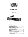
GENERAL DESCRIPTION ..............................................4
UNPACKING .....................................................................4
MECHANICAL INSTALLATION...........................................4
MAINS POWER...................................................................5
FRONT PANEL CONTROLS...........................................6-9
REAR PANEL CONTROLS..........................................10-11
INTERNAL CONTROLS...............................................12-14
MODES..............................................................................15
CABLING...........................................................................16
PARTY LINE, TECHNICAL CONCEPT.............................17
WARRANTY......................................................................17
TECHNICAL SPECIFICATIONS.......................................17
DESIGN CRITERIA...........................................................18
2
User Manual PS 4379 - Issue 1 © 2007 ASL Intercom, Utrecht, The Netherlands
1.0 IMPORTANT SAFETY INSTRUCTIONS !
Please always follow these instructions to help ensure
against injury to yourself and damage to the system.
1)
Read all safety and operatinginstructions
before you operate the apparatus.
2)
Retain all safety and operating instructions
for future reference.
3)
Heed all warnings on the apparatus and in the
safety and operating instructions.
4)
Follow all installation, operating and use
instructions.
5)
Unplug the apparatus from the AC power out
let before cleaning. Use only a damp cloth for
cleaning the exterior of the apparatus.
6)
Do not use accessories or attachments not
recommended by the manufacturer, as they
may cause hazards and void the warranty.
7)
Do not operate this apparatus in high
humidity areas or expose it to water or
moisture.
8)
Do not place the apparatus on an unstable
cart, stand, tripod, bracket or table. The appa
ratus may fall, causing serious personal injury
and damage to the apparatus.
9)
10)
Do not block or cover any openings in the
apparatus. These are provided for ventilation
and protection from overheating. Never place
the apparatus near any heat sources such as
radiators, heat registers, stoves, or other
apparatus (including amplifiers) that produce
heat. Do not place the apparatus in an
enclosure such as a cabinet without proper
ventilation.
Operate the apparatus using only the type of
power source indicated on the marking label.
Unplug the apparatus' power cord by gripping
the power plug, not the cord.
11)
Insert the plug properly. Do not defeat the
safety purpose of the polarized or groundingtype plug. An American polarized AC line plug
has two blades with one wider than the other.
This plug will fit only one way into the power
outlet. This is a safety feature. If you are
unable to insert the plug fully into the outlet,
try reversing the plug. If the plug still fails to fit,
contact an electrician to replace the obsolete
outlet. A grounding type plug has two blades
and a third grounding prong. The wide blade
or the third prong are provided for your safety.
If the provided plug does not fit into your out
let, consult an electrician to replace the
obsolete outlet.
12)
Route power supply cords so that they are not
likely to be walked on or pinched by items
placed upon or against them. Pay particular
attention to cords at plugs, convenience
receptacles, and the point where they exit
from the apparatus.
13)
Do not overload wall outlets or extension
cords, as this can result in a risk of fire or
electrical shock.
14)
Unplug this apparatus during lightning storms
or when unused for long periods of time.
15)
Never insert objects of any kind into the
apparatus through openings, as the objects
may touch dangerous voltage points or short
out parts. This could cause fire or electrical
shock.
16)
Refer all servicing to qualified service
personnel. Servicing is required when the
apparatus has been damaged in any way,
such as when the power-supply cord or plug is
damaged, liquid has been spilled or objects
have fallen into the apparatus, the apparatus
has been exposed to rain or moisture, does
not operate normally, or has been dropped.
User Manual PS 4379 - Issue 1 © 2007 ASL Intercom, Utrecht, The Netherlands
3
2.0
GENERAL DESCRIPTION
The PS 4379 is designed to be a four channel loudspeaker
master unit in an ASL Intercom system and can be used in
portable as well as fixed applications.
It incorporates a power supply, auxiliary inputs, program
input, headset connector, loudspeaker and a gooseneck
microphone, stage announce output, IFB Mode, Paging
Mode, Near Station Mode and Extended Mode (see section
9 for further explanation of each Mode) and provides full
duplex communications within an ASL intercom system. The
PS 4379 RM model has a small built-in electret microphone.
The power supply supplies power to a max. of 40 Beltpacks
or 20 Speaker Stations.
Each channel has a Volume (listen level) control, a Talk and
Call button with LED indicators and a two-stage sidetone
trimmer. A master volume controls the total speaker/headset
volume.
The unit is equipped with a limiter for the gooseneck microphone, allowing the user to speak close into the microphone
without giving rise to overload and distortion. Loudspeaker
dimming is automatic when the microphone is active. Private
conversation may be carried out via the headset connector
with a headset or telephone handset. When a headset is
connected, both gooseneck microphone and speaker are
switched of automatically. The speaker can be then switch
on again with the Speaker on/off button.
As an option, a XLR-6 headset connector can be fitted for
binaural use of the headset. By setting internally mounted
jumpers, each of the 4 channels can be assigned to either
the left or the right headset can, or to both headset cans.
An electronically balanced input allows volume controlled
monitoring of the audio signal. This is for local use only, it
will not appear on the intercom lines.
Special attention has been paid to the intelligibility of speech.
By applying low noise/high speed op-amps, a speech presence filter and a specially developed high power bridged
headphone amplifier, communication is very comfortable
even in environments with high background noise level.
There is a separate amplifier for the loudspeaker.
The unique CALL system provides both a flashing red LED
and a very distinctive and characteristic sound signal. A
short push of the CALL button will make the LED flash. The
Call sound signal (buzzer) will be activated when holding the
button for two seconds. In case the sound signal is undesirable, all buzzers can be muted with the "All buzzers
on/off" button and the volume of the buzzer can be adjusted
at the front panel.
The pre-amplified microphone signal is electronically balanced available at a 3 pin male XLR. This signal can be sent to
paging systems.
Fully electronic switching increases reliability and allows for :
- 'soft' microphone ON switching, latched or
momentary
- remote Mic Mute facility.
- automatic speaker attenuation (adjustable), when
the microphone is activated.
3.0 UNPACKING
The shipping carton contains the parts listed below:
`
* The PS 4379
* power cable
* User manual
* 2 x Fuses
* 19" rackmount flares
If any are missing, contact your dealer.
ASL has taken great care to ensure this product reaches you
in flawless condition.
After unpacking the unit please inspect for any physical
damage to the unit, and retain the shipping carton and
relevant packing materials for use should the unit need
returning.
If any damage has occured, please notify your dealer immediately so that a written claim can be initiated. Please also
refer to the guarantee section of this manual.
4.0 INSTALLATION
This PS 4379 will form part of an existing or new intercom
system, and connection to it is straightforward.
Adequate ventilation must be provided by allowing sufficient
space around the sides and rear of the unit to ensure free
circulation of air. Forced cooling is not required. The power
supply is mounted on the bottom of the unit, and after a period of time it will feel hot to the touch at the bottom. This is
normal, and should be no cause for alarm.
To connect the PS 4379 onto the intercom system, use professional flexible microphone cable with 2 wires and 1 shield
only.
4
Connect the system intercom cables into the LINE connector
sockets on the rear panel. Finally, when private conversation
is desired, connect the headset plug into the headset connector on the front of the front panel.
The PS 4379 is fully protected against mis-wiring (reverse
power) or short circuit in the interconnect cables.
A special kit is included for mounting the PS 4379 in a 19"
rack, taking 2U of rack-space.
User Manual PS 4379 - Issue 1 © 2007 ASL Intercom, Utrecht, The Netherlands
5.0 MAINS POWER
The PS 4379 may be connected to the mains power outlet to
which other audio equipment is connected. The outlet should
have a clean earth. Avoid using mains power outlets, which
also power dimmer controlled lighting equipment.
Before connecting the unit to its AC power source, check if
the mains voltage of the unit (100 V - 240 V) is in accordance with your local mains voltage.
WARNING
This appliance must be earthed
IMPORTANT
The wires in this mains lead are colour coded in accordance
with the following code:
As the colours of the wires in the mains lead may not correspond with the coloured markings identifying the terminals in
your plug, proceed as follows:
-
-
The wire that is coloured green-and-yellow must be
connected to the terminal in the plug, which is
marked with the letter "E", or by the ground symbol,
or is coloured green.
The wire that is coloured blue must be connected to
the terminal that is marked with the letter "N" or
coloured black.
The wire that is coloured brown must be connected
to the terminal that is marked with the letter "L" or
coloured red.
Those units that are supplied to the North American market
will have an integral moulded 3-pin connector, which is provided to satisfy required local standards.
green and yellow / safety ground
blue
/ neutral
brown
/ live
5.1 POWERING UP
Powering up procedure:
-
Make sure that the power switch at the back of the
unit is OFF.
-
Connect the power cord to the rear of the station.
-
Plug the other end of the power cord into a
PROPERLY GROUNDED outlet.
-
Turn on the power with the red button. The red
overload LED will light up for about 3 seconds, then
extinguishes and the green power LED will switch
on, indicating the station is active.
For further installation and operation see the concerning
sections.
5.2 SAFETY EARTHING
The green-and-yellow wire of the mains cord must always be
connected to the electrical installation safety earth or ground.
It is essential for personal safety as well as for proper operation of the PS 4379 and the other connected stations. This
wire is internally connected to all exposed metal surfaces.
Any rack framework into which this unit
might be mounted shall be connected to the same grounding
circuit.
The PS 4379 employs professionally designed audio input
and output circuits which do not require the disconnection of
any safety earth for the avoidance of hum loops.
5.3 MAINS POWER SETTING
The unit has a switch mode power supply and accepts mains voltages from 100 - 240 VAC (50 / 60 Hz).
Mains Fuse
For all voltages : T 1250.
User Manual PS 4379 - Issue 1 © 2007 ASL Intercom, Utrecht, The Netherlands
5
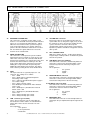
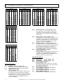
6.0 FRONT PANEL CONTROLS & CONNECTOR
1
LISTEN LEVEL control knobs
These knobs preset the listen level for each
channel separately.
2
TALK buttons
These buttons allow you to talk to each channel
separately or simultaneously.
The large green LED is lit when the talk function for
that channel is activated. Should one talk to a channel
which is in IFB or PAGING mode by pressing and
holding that TALK button, the other lit TALK buttons
will switch off for as long as the IFB / PAGING mode
TALK button is pressed (for further explanation of the
Modes see section 9). To talk to an IFB / PAGING
channel and additionally to a intercom channel, one
should also press and hold the TALK button of the
intercom channel. If in IFB mode and one would like
to talk to all channels of which the TALK LEDs are lit,
than this can be achieved by setting the corresponding, internal dip switch "IFB and TALK" to 'on' (see
8.0 Internal controls / Dip switches).
Latched switching:
When a TALK button is pressed shortly, the
microphone signal is sent to the chosen channel and
the TALK button latches electronically. When pressed
again, the Talk function will switch off.
Momentary switching:
When holding a TALK button pressed while talking,
the microphone signal will be sent to the chosen
channel until the button is released. Then the talk f
unction will switch off automatically.
`
3
6
CALL buttons
These push buttons activate the call system, for each
channel separately.
A momentary push will sent a visual CALL signal to all
stations connected to the intercom channel and the call
LEDS will start flashing. When holding the CALL
buttons for 2 seconds the buzzer will be activated, if
there is no buzzer mute on this channel. After the
CALL button is released the LEDS will continue to flash
for further 2 seconds.
4
TALK to ALL
When the TALK to ALL button is pressed and held,
one will talk to all intercom channels simultaneously
and the green LEDs of all channels will light up except for the channels which are in IFB or PAGING
mode. To also include the channels which are in IFB or
PAGING mode, the dip switch IFB and TALK ALL has
to be switched to 'on' (see 8.0 Internal controls / Dip
switches).
5
CALL ALL
When the CALL ALL button is pressed shortly a
visual call signal is sent to all channels and the red
LEDs will start flashing. When holding the CALL
buttons for 2 seconds the buzzer will be activated,
should no buzzer mute be activated for that channel.
After the CALL button is released the LEDs will
continue to flash for further 2 seconds. Channels which
are in IFB or PAGING mode do not receive CALL
signals.
6
MASTER VOLUME
This knob adjusts the volume of the speaker or
headset.
7
STAGE ANNOUNCE
This push button routes the microphone signal
directly to a line level output at the back of the unit.
The microphone signal will not be sent to the intercom
channel even if the TALK LEDs are lit. This can be
changed by setting the corresponding internal dip
switch (STAGE ANN. and TALK) to 'on' (see section
8.0 Internal controls / Dip switches).
The Aux signal can also be routed to the STAGE
ANNOUNCE output by setting the corresponding dip
switch (AUX and STAGE ANN.) to 'on' (see section
8.0). In EXTENDED Mode only the microphone signal
of the Master unit will be routed to the STAGE
ANNOUNCE output of the master. This can be
changed by setting the corresponding dip switch
(Stage announce mic. Select) to 'on'(see section 8.0) in
which case each unit will use its own Stage Announce
output and microphone.
User Manual PS 4379 - Issue 1 © 2007 ASL Intercom, Utrecht, The Netherlands
6.0 FRONT PANEL CONTROLS & CONNECTOR continued
8
SPEAKER ON/OFF
With this button the speaker can be switched on or
off. The LED within the button will light up if the
speaker is switched on. If the speaker has been
switched on when a headset was connected, the
speaker will automatically switch off. By pushing the
speaker on/off button, the speaker will switch back on
and the audio can be heard over both the speaker and
the headset. When disconnecting the headset, the last
setting of the speaker will remain.
9
SIDETONE LEVEL trimmers
These trimmers (one for each channel) adjust the level
of your own voice as it is heard over the speaker or
headset. It prevents the speaker from feeding back into
the gooseneck microphone.
Adjustment procedure for all sidetone trimmers:
- set trimmer in start position : fully clockwise.
- switch off the microphone of all connected
(speaker!) stations (TALK button).
- switch on the microphone of the PS 4379.
- turn up volume.
- speak into the headset microphone.
- adjust the listen level to a minimum by turning the
sidetone trimmers.
Adjusting the sidetone does not affect the level of your
voice as it is heard by other stations.
10
11
SPEAKER ATTENUATOR trimmer
This trimmer allows you to dim the speaker
automatically, when the gooseneck microphone is
switched on. It prevents:
- unit feedback if sidetone rejection is not sufficient.
- system feedback or a 'hollow' sound when the
gooseneck microphones of other speaker stations
on the same channel are activated simultaneously.
Adjustment procedure :
- switch off TALK buttons.
- inject an audio signal on an intercom channel.
- turn up volume.
- activate microphone and adjust the desired amount
of attenuation.
The speaker attenuator has no effect when a headset
is used and the speaker is switched off.
12
BUZZER VOLUME trimmer
This trimmer adjusts the volume of the internal buzzer.
The buzzer is activated if you press a CALL of the
PS 4379 (or if a CALL button of any other station is
pressed to which the PS 4379 is connected), for
longer than 2 seconds, and if the buzzers on these
channels are not muted.
13
PGM VOLUME
This knob adjusts the volume of the PGM input. The
signal of the PGM input can only be heard on the
PS 4379 and does not appear on the intercom lines.
SIDETONE HI trimmers
These trimmers (one for each channel) control the
rejection in the high frequency range. It compensates
the capacity of the interconnecting cables. It prevents
the speaker from feeding back
into the gooseneck microphone (unit feedback). For
adjustment procedure see above in point 9.
Manual PS 4379 - Issue 1 © 2007 ASL Intercom, Utrecht, The Netherlands
7
6.0 FRONT PANEL CONTROLS & CONNECTOR continued
14
HEADSET connector
A XLR-4 type connector for the connection of a local
headset when private conversation is desired.
The headset must have a can impedance of 200 ohms
(or greater), or each a minimum of 400 ohm when in
parallel. The headset microphone may be of the dyna
mic or electret type.
Pin assignments :
1.
Shield mic. (GND)
2.
mic. +
3.
phones +
4.
phones
When connecting a headset, speaker and gooseneck
microphone will be switched off automatically. The
speaker can be switched on again by pushing the
SPEAKER on/off button. The PS 4379 can optionally
be equipped with a XLR-6 headset connector for
binaural use. Jumpers on the front PCB board inside
determine the destination of the listen signals on the
headset.
Each listen signal of the four channels can independently be placed:
on the left or right can.
on both cans.
15
GOOSENECK MICROPHONE
A high quality electret noise cancelling microphone.
A limiter prevents the mic pre-amp from clipping when
speaking close in the microphone. The microphone is
automatically disabled when a headset is used.
16
17
8
LOUDSPEAKER
A high quality loudspeaker driven by a 1.3 Watt
amplifier. The speaker will switch off as soon as a
headset is connected. It can be switched on again by
pressing the Speaker on/off switch.
AUX (per channel)
By pushing the aux button of a channel, the auxiliary
signal is routed to the corresponding channel. With
these pushbuttons the auxiliary input can be routed to
any or all channels separately. (To adjust the volume
of the auxiliary, see point 17 AUX Level / IFB DIM.
18
AUX LEVEL / IFB DIM
With this knob the Volume of the AUXILlARY and
the dim factor of the IFB can be set for each
channel separately.
- AUX LEVEL
The auxiliary can be assigned to any or all of the
four intercom channels. The auxiliary volume for
each channel can be adjusted separately by
pushing and holding -for example- the AUX
button of channel A for 2 seconds till the light
starts flashing. The AUX level can now be
adjusted on the AUX Level knob and is confirmed
by pushing the AUX LEVEL knob. The volume
setting is indicated on the LED bar (see point 18).
- IFB DIM
With the IFB DIM you adjust the dim factor of the
IFB auxiliary when talking over that channel.
Factory setting is that the auxiliary volume will
reduce by 50 %. This can be adjusted with the
IFB DIM knob for each channel separately. If for
example channel A has been selected to be an IFB
channel the dim factor can be adjusted by
pushing and holding the IFB button A for 2 seconds
till the light starts flashing. The IFB dim factor can
now be adjusted on the IFB DIM Level
knob and confirmed by pushing the knob. The dim
factor is indicated on the LED bar (see point 18).
19
AUX LEVEL / IFB DIM FACTOR LED BAR
This LED Bar indicates the settings of all DIM factors
and Auxiliary volumes as described in the equivalent
sections.
20
ALL MIC MUTE
With this pushbutton all microphones of the connected
stations and of the PS 4379 can be switched off. Each
user station can activate the talk function again by
pushing a TALK button.
21
ALL BUZZER MUTE
With this button all buzzers of the connected stations
and of the PS 4379 can be muted.The buzzers stay
muted until the ALL BUZZERMUTE button is switched
off again.
User Manual PS 4379 - Issue 1 © 2007 ASL Intercom, Utrecht, The Netherlands
6.0 FRONT PANEL CONTROLS & CONNECTOR continued
22 SET UP LOCK
The setup of the AUX, IFB and Buzzer mutes can be
locked by pushing a small pin into the SETUP lock. It
will be unlocked by pushing it again. When pushing and
holding the set up lock, the light intensity of the LEDs of
the MIC MUTE-, BUZZER MUTE-, AUX- and IFB LEDs,
can be increased by turning the AUX level / IFB Dim
knob. In "Near Station" mode (see section 9.0 Modes)
one can adjust the dim factor per channel by pushing
and holding the set up lock as well as the TALK button
of the required channel and turning the AUX level / IFB
Dim knob. The dim factor will be shown on the Aux
level/ IFB dim LED bar.
23 SYSTEM LINK LEDs (per channel)
These LEDs illuminate if another ASL Intercom System
has been connected to the PS 4379 through the
"System Link" connector at the corresponding channel.
The Line Impedance is now provided by the other
Intercom system and the internal line impedance for
that channel is switched off. The Buzzer mute function
on the system-linked channels can now only be
controlled by the connected system, while the Buzzer
Mute on the channels which are not in System link will
still be controlled by the PS 4379. The Mic Mute signals
given by the other Intercom system are also sent to the
user stations which are connected to the PS 4379 on the
channel which is in system link. If a Mic Mute is given by
the PS 4379, it is only sent to its own channels and does
not mute the microphones of the other Intercom System.
24 ON / OVERLOAD LEDs (per channel)
These LEDs will indicate the status of each channel.
The LEDs will illuminate green if power is supplied by
the internal power supply.
The LEDs will flash red, when the corresponding
channel is reaching an overload. In this case the
channel is still functioning but will shut off, if further units
are added. If all LEDs are flashing the complete system
is close to going into overload and should additional
units be added, the channel will shut down. The LEDs
will go constantly red, when too many units have been
connected or if there is a short circuit on the corresponding channel. If all LEDs are lit red and one or more
channels are switched off, a master overload occurred.
In this case the channel with the lowest load will switch
off. If that is not sufficient the next channel will switch off
- and so on. The circuit-breaker resets automatically 3
seconds after the cause of the overload has been
removed, and restores line power automatically.
The LED will also light up red for a few seconds every t
time mains power is switched on.
25 MIC MUTE (per channel)
With these pushbuttons the microphones of the
connected stations can be switched off for each channel
separately. Each user station can activate its microphone again by pushing the TALK button.
26 BUZZER MUTE (per channel)
With these pushbuttons the buzzers of all stations
connected to that channel can be muted, until the
BUZZER MUTE button is switched off again.
27 IFB (per channel)
With these pushbuttons a channel can be put into IFB
Mode. This is used for monitoring purposes and one
way communication from i.e. a director or producer to a
talent. If a channel is put into IFB mode, the AUX button
of that channel will switch on automatically and the
auxiliary signal of the IFB auxiliary input will be routed to
that channel. If no IFB-Auxiliary is needed, it can be
switched off by switching off the aux button of that
channel. The AUX-input can also be routed to an IFB
channel by switching the corresponding dip switch (IFB
or AUX input for IFB) to 'on' (see section 8.0 Internal
controls / Dip switches).
The TALK button of an IFB channel will be momentary
and not latching and must be pressed while talking.
When pressing the TALK button of an IFB channel, the
aux volume will be dimmed automatically by 50 %. This
dim factor can be adjusted (see point 17 AUX Level /
IFB DIM).
The TALK buttons of the intercom channels will switch
off for as long as the IFB TALK button is pushed. This
can be changed by setting the corresponding internal dip
switch (IFB and TALK) to 'on' (see section 8.0 Internal
controls / Dip switches).
TO INCREASE LED LIGHT INTENSITY OF MIC MUTE,
BUZZER MUTE, AUX AND IFB see point 21 'Set up lock'.
User Manual PS 4379 - Issue 1 © 2007 ASL Intercom, Utrecht, The Netherlands
9
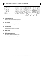
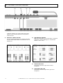
7.0 REAR PANEL CONTROLS & CONNECTOR
28
EXTENDED STATION LINK
This connector is used when 2 units (either 2 x PS
4379 or 1 x PS 4379 with PS 4379) should be linked to
form a 10 or 12 channel unit. When linked, 1 station
will be the master with an active speaker and gooseneck /electret microphone. The speaker and microphone of the other unit will be switched off. The CALL
ALL and TALK ALL signals will also be sent to the
channels of the extended unit.
29
NEAR STATION LINK
This connector is used to prevent system feedback
when two PS 4379 / PS 4379 are used close to each
other in the same room. This connection will dim the
listening level should the 'near station' talk on the same
channels the 'linked' station is listening to. The dim
factor can be adjusted per channel by pressing and
holding the 'set up lock' button and pressing and
holding the TALK button of the channel. The adjustment is done by turning the Aux level/ IFB dim knob.
30
31
10
GPIO
This 9-pin connector is a general purpose in - out
connector. The settings are as follows:
- Pin 1 = GND
- Pin 2 = GPIO output 1 (default=microphone
functioning, active = high)
- Pin 3 = output 2 (default=External power supply is
used, active = high)
- Pin 4 = Relay common contact
- Pin 5 GPIO input 2 (default=mic mute all button,
active = low)
- Pin 6 = GPIO input 1 (default=buzzer mute all
button, active = low
- Pin 7 = GPIO input 3 (default=tall all button,
active = low
- Pin 8 = Relay normally open contact
- Pin 9 = Relay normally open contact
LINE connector (per channel)
These XLR-3 connectors are for connecting the
PS 4379 to the remote stations, via standard microphone cable. There are two connectors for each
channel.
Pin assignments:
1. 0V / ground
2. +30 V power wire
3. Audio wire
32
SYSTEM LINK connector
Input for the cable of an external party-line Intercom
system which has its own power supply. If any or all of
the channels are to be connected to another intercom
system, then these connectors will accept the
communication signals from the other system without
impedance problems and without using power from the
other system.
33
LIFT / GROUND switch
With these switches the pin 1 of either the AUX input,
Program input or IFB input XLRs are lifted from ground
when in 'Lift' position.
34
AUX INPUT connector (auxiliary)
This XLR female connector is electronically balanced
and used to connect a line level signal which can be
routed to any intercom channel by using the AUX
buttons.
Pin assignments:
1.
0V / ground
2.
Signal +
3.
Signal -
35
PROGRAM INPUT connector
This XLR female connector is electronically balanced
and used to connect a line level signal which will be
routed to the loudspeaker of the PS 4379 only.
36 IFB INPUT connector (AUX)
This XLR female connector is electronically balanced
and used to connect a line level signal which will be
routed to the channels which are in IFB mode.
Pin assignments:
1.
0V / ground
2.
Signal +
3.
Signal 37
MIC DIRECT OUT
This XLR3 male connector is electronically balanced
and outputs the pre-amplified microphone signal at line
level.
User Manual PS 4379 - Issue 1 © 2007 ASL Intercom, Utrecht, The Netherlands
7.0 REAR PANEL CONTROLS & CONNECTOR continued
38
STAGE ANNOUNCE OUT
This XLR 3 male connector is electronically balanced
and outputs the pre-amplified microphone signal at line
level when the STAGE ANNOUNCE button is used.
39
EXT. SPEAKER
An external speaker can be connected to this 6,3 mm
Jack. In this case the internal speaker switches off and
the audio is sent to the external speaker.
40
DC POWER INPUT
These two connectors allow an external 12-28V DC
5A, input as a back-up for the internal mains power
supply, or should no 110/240 V mains supply be
available.
41
POWER ON/OFF
This switch is used to switch on the internal power
supply.
42
MAINS POWER CONNECTION
Mains inlet with built in fuse holder. 90 -240 V AC,
50 - 60 Hz.
Power consumption 200 Watt, Fuse: 4 Amp slow blow.
User Manual PS 4379 - Issue 1 © 2007 ASL Intercom, Utrecht, The Netherlands
11
No. 5
12
RESERVED
1
TALK Momentary Ch. A
RESERVED
2
TALK Momentary Ch. B
PAGING Channel A
TALK Momentary Ch. C
PAGING Channel B
Dip D
4 3
TALK Momentary Ch. D
5
IFB and TALK (factory setting = 'off')
If this dip switch is in 'on' position, and one presses
and holds the TALK button of the IFB Channel, the
microphone signal will also be sent to all intercom
channels of which the TALK LED is lit. (For IFB
functions see section 9.0 MODES)
PAGING and TALK (factory setting = 'off')
If this dip switch is in 'on' position, and one presses
and holds the TALK button of the PAGING channel,
the microphone signal will also be sent to all
intercom channels of which the TALK LED is lit.
(For PAGING functions see section 9.0 MODES)
STAGE ANNOUNCE and TALK
(factory setting = 'off')
If this dip switch is in 'on' position, and one presses
and holds the STAGE ANNOUNCE button the
microphone signal will also be sent to all intercom
channels of which the TALK LED is lit.
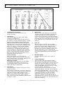
DIP SWITCH BLOCK B
No. 6
No. 5
No. 4
DIP SWITCH BLOCK A
No. 6
6
No. 3
1
Mic mute block
Reserved
Speaker dim and STAGE ANN.
2
1
IFB and TALK ALL (factory setting = 'off')
If the dip switch is in 'on' position, and the TALK
ALL button is pushed and held, the microphone
signal will also be routed to the channels which are
in IFB mode.
No. 1
Reserved
Stage announce mic. Select
Dip F
4 3
AUX and STAGE ANN.
5
2
No. 4
No. 2
6
Dip C
4 3
PAGING Channel C
5
PAGING Channel D
CALL Receive Channel A
6
RESERVED
1
RESERVED
2
CALL Receive Channel B
CALL Receive Channel C
RESERVED
Dip B
4 3
CALL Receive Channel D
RESERVED
STAGE ANN. and TALK
1
IFB-or AUX-input for IFB Ch. C
2
IFB-or AUX-input for IFB Ch. A
5
PAGING AND TALK
6
IFB-or AUX-input for IFB Ch. B
1
IFB and TALK
2
Dip E
4 3
IFB and TALK ALL
5
Dip A
4 3
IFB-or AUX-input for IFB Ch. D
PAGING and TALK ALL
6
RESERVED
5
RESERVED
6
PGM DIM
8.0 INTERNAL CONTROLS / DIP SWITCHES
PGM Dim
(factory setting = 'off')
If this dip switch is in 'on' position the program
volume will dim to zero when a TALK LED is lit.
PAGING and TALK ALL
(factory setting = 'off')
If this dip switch is in 'on' position, and the TALK
ALL button is pushed and held, the microphone
signal will also be routed to the channels which are
in paging mode. The CALL signal will also be sent
to these channels. (For PAGING functions see
section 9.0 MODES).
No. 3
No. 2
No. 1
RESERVED
(factory setting = 'off')
RESERVED
(factory setting = 'off')
CALL RECEIVE Channel D
(factory setting = 'off')
If this dip switch is in 'on' position, the corresponding channel will still receive a CALL signal even if
the channel is switched off.
CALL RECEIVE Channel C
(factory setting = 'off') (Same as for No. 4)
CALL RECEIVE Channel B
(factory setting = 'off') (Same as for No. 4)
CALL RECEIVE Channel A
(factory setting = 'off') (Same as for No. 4)
User Manual PS 4379 - Issue 1 © 2007 ASL Intercom, Utrecht, The Netherlands
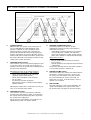
8.0 INTERNAL CONTROLS / DIP SWITCHES
DIP SWITCH BLOCK C
DIP SWITCH BLOCK F
No. 6
No. 5
No. 4
No. 6
No. 3
No. 2
No. 1
RESERVED (factory setting = 'off')
RESERVED (factory setting = 'off')
PAGING Channel D
(factory setting = 'off')
If this dip switch is in 'on' position, the
corresponding channel will be set to PAGING
mode. (For PAGING functions see point 9.0
MODES)
PAGING Channel C (factory setting = 'off')
(Same as for No. 4)
PAGING Channel B (factory setting = 'off')
(Same as for No. 4)
PAGING Channel A (factory setting = 'off')
(Same as for No. 4)
No. 5
DIP SWITCH BLOCK D
No. 6
No. 5
No. 4
No. 3
No. 2
No. 1
RESERVED (factory setting = 'off')
RESERVED (factory setting = 'off')
TALK MOMENTARY Channel D
(factory setting = 'off')
If this dip switch is in 'on' position, the
corresponding TALK button of that channel will be
set to momentary only.
TALK MOMENTARY Channel C
(factory setting = 'off')
(Same as for No. 4)
TALK MOMENTARY Channel B
(factory setting = 'off')
(Same as for No. 4)
TALK MOMENTARY Channel A
(factory setting = 'off')
(Same as for No. 4)
No. 4
DIP SWITCH BLOCK E
No. 6
No. 5
No. 4
No. 3
`
No. 2
No. 1
RESERVED (factory setting = 'on')
RESERVED (factory setting = 'on')
IFB or AUX INPUT for IFB Channel D
(factory setting = 'on')
If this dip switch is switched off, the auxiliary of the
AUX input is routed to the IFB channel.
IFB or AUX INPUT for IFB Channel C
(factory setting = 'on')
(Same as for No. 4)
IFB or AUX INPUT for IFB Channel B
(factory setting = 'on')
(Same as for No. 4)
IFB or AUX INPUT for IFB Channel A
(factory setting = 'on')
(Same as for No. 4)
No. 3
No. 2
No. 1
STAGE ANNOUNCE MIC. SELECT
(factory setting = 'off')
This dip switch is only for use in EXTENDED mode
(See section 9 MODES). If the dip switch is in 'off'
position, the gooseneck or headset microphone and
the Stage Announce output of the master unit is
used. If the dip switch is in 'on' position, the micro
phone and stage Announce output of the unit is
used, of which the STAGE ANNOUNCE button is
pressed.
SPEAKER DIM and STAGE ANNOUNCE
(factory setting = 'off')
In 'off' position the Speaker of the PS 4379 will not
reduce in volume when the STAGE ANNOUNCE
button is pressed. In 'on' position, the Speaker and
Program volume will be dimmed to zero as long as
the STAGE ANNOUNCE button is pressed.
STAGE ANNOUNCE and AUXILIARY
(factory setting = 'off')
In 'off ' position, no aux signal will be sent to the
STAGE ANNOUNCE output. In 'on' position, the
Aux signal will be sent to the STAGE ANNOUNCE
output. When pressing and holding the STAGE
ANNOUNCE button, the AUX volume will be
dimmed to a set level. This dim factor is set by
pressing and holding the STAGE ANNOUNCE
button and turning the AUX level / IFB dim knob.
The set level will be shown on the AUX level / IFB
LED bar. The dim factor is stored by shortly
pressing the AUX level / IFB knob.
By first pressing the STAGE ANNOUNCE button,
releasing it and pressing and holding it again within
1 second, the AUX level LED bar will show the
volume setting of the Auxiliary. This can be then
adjusted by turning the AUX level / IFB Dim knob.
RESERVED
RESERVED
MIC MUTE BLOCK
(factory setting = 'off')
When in SYSTEM LINK and the dip-switch is in 'off'
position the mic mute signals of the connected
intercom system will be routed to the outputs of the
PS 4379. If the dip-switch is in 'on ' position, the
Mic Mute signals of the connected intercom signals
will not be detected by the PS 4379 and not routed
to the outputs of the unit.
User Manual PS 4379 - Issue 1 © 2007 ASL Intercom, Utrecht, The Netherlands
13
8.0 INTERNAL CONTROLS continued
Inside the unit there are several controls that can be
adjusted. These internal controls are located on the
main PC board.
43
14
BINAURAL JUMPER SETTING
For each channel separately, these jumpers determine
how the audio of that channel can be heard in case of
binaural use.
44
PGM ROUTING JUMPERS
With these two jumpers you can determine, for binaural
applications, how the PGM signal is controlled and
where it is to be sent to.
45
HEADSET MIC GAIN
This trimmer controls the gain of the headset
microphone.
46
GOOSENECK MIC GAIN
This trimmer controls the gain of the gooseneck
microphone.
User Manual PS 4379 - Issue 1 © 2007 ASL Intercom, Utrecht, The Netherlands
9.0 MODES
IFB Mode
This mode is used for one way 1 to 1 communication,
e.g. director to talent. The talent will constantly listen to
the IFB Aux signal or the AUX signal if the corresponding dip switch is in 'off' position (see point 8
internal controls / dip switches). The director can talk
over the Aux signal by pushing and holding the IFB
TALK button. The AUX volume will be dimmed to a set
IFB dim factor and the microphone signal will be added
to the IFB line.
To set the AUX volume see 'AUX BUTTON' (point 4.0
No. 17 )To set the IFB dim factor see 'IFB Button'
(point 4.0 No. 17)
In IFB mode the buzzer and mic mute buttons are
disabled.
PAGING Mode
This mode is used for one way communication to
dressing rooms etc. and can be 1 person to many. An
AUX signal can be sent to paging receivers of which
users can adjust their own listen volume. When the
TALK button of the PAGING channel is pressed and
held, it will override the volume setting of the receivers
to a preset volume. The AUX signal will be dimmed by
the preset PAGING Dim factor and the MIC signal of
the PS 4379 will be added. For information on how to
adjust the AUX volume, see: 'AUX Button' . The DIM
factor is set by pressing and holding the TALK button
and turning the AUX level / IFB dim knob. The set level
will be shown on the AUX level / IFB LED bar.
In PAGING Mode the Buzzer mute on this channel is
automatically activated and the buzzer mute button and
mic mute are disabled. Should the channel be in both
PAGING mode and System Link, the buzzer mute
button will be disabled but the buzzer mute will not be
activated. The PS 4379 will assume that the buzzer
mute is activated by the connected intercom station.
EXTENDED STATION Mode
Two stations (PS 4379 and/or PS 6379) can be linked
to form one station of 8 - 12 channels. One unit will be
the master unit and will have an active speaker and
microphone. The speaker and gooseneck microphone
of the other unit (slave) will be switched off. The head
sets will continue to work on both units. Which station
will be master is decided by the link cable. The link
cable has a master and a slave connector and the unit
connected to the master connector will be the master
unit.
The TALK to ALL, CALL ALL, BUZZER MUTE ALL and
MIC MUTE ALL buttons will function on both units.
The STAGE ANNOUNCE of the slave unit will be
routed to the Stage Announce output of the master
unit. To also use the microphone and STAGE
ANNOUNCE output of the slave unit, the dip switch
'Stage Announce mic select' has to be put into 'on'
position (see section 8 internal controls / Dip switches).
To connect 2 stations as "EXTENDED STATION', an
Extended Station 379 A link cable is needed.
To connect 3 stations you need an Extended Station
379 A and a Extended Station 379 B cable.
NEAR STATION Mode
Multiple PS 4379 or PS 6379 stations in one room can
be linked as 'NEAR STATIONS'. When linked, the
listen levels will be dimmed if a near station is talking
on the lines your own station is listening to. For
example: 3 stations are mounted in a directors room
and all 3 stations have the same 4 channels available.
Station 1 talks to channel A and the listening volume of
channel A will be dimmed by the set dim factor on
station 2 + 3 to prevent system feedback. This will only
be the case if the speakers are switched on. For
information on how to change the NEAR STATION
DIM factor, please see point 4.0 No. 20)
To connect 2 stations as "NEAR STATIONS', a Near
Station 379 A link cable is needed.
To connect 3 stations you need a Near Station 379 A
and a Near Station 379 B cable.
User Manual PS 4379 - Issue 1 © 2007 ASL Intercom, Utrecht, The Netherlands
15
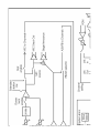
10.0 CABLING
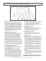
For the PRO Series Intercom system the interconnecting cables are of the shielded two-conductor
microphone cable type and the intercom line
connectors are of the XLR-3 type. Audio and Call
signals are on XLR pin 3, DC power is on XLR pin 2.
XLR pin 1 is connected to the shield of the cable which
functions as the common return for audio and power.
Since the audio signal is transferred in an unbalanced
*
way, certain rules have to be obeyed when installing
the cables of an intercom network. This is to avoid
earth loops and to minimize power loss and the
possible effect of electromagnetic fields.
These rules are:
- Use high quality (multipair) cable.
For interconnecting user stations, power supplies and
accessories in an ASL Intercom network, use high
quality shielded two conductor (minimum 2x 0.30 mm2)
microphone cable only.
In case of a multi channel intercom network, use high
quality microphone 'multipair' cable only, each pair
consisting of two conductors (minimum 2x 0.15 mm2)
with separate shield. Multipair cable should also have
an overall shield.
- Use flexible cables.
Use flexible single and multipair microphone cable
instead of cable with solid cores, especially when the
cable is subjected to bending during operation or
installation.
- Separate cable screen to XLR pin 1.
The screen of each separate microphone cable and/or
the screen of each single pair in a multipair cable,
should be connected to pin 1 of each XLR-3 connector.
Do not connect this cable screen to the metal housing
of the connector or to metal wall boxes (outlets).
See page 10 for Earthing Concept.
- Cable trunks, connection boxes and overall
multipair cable screen to clean earth.
Metal cable trunks, metal connection boxes and overall
multipair cable screen should be interconnected and, at
one point (the 'central earthing point') in the intercom
network only, be connected to a clean earth or a safety
earth.
See page 10 for Earthing Concept.
- Keep metal connection boxes and cable trunks
isolated from other metal parts.
Metal housings for intercom cables and connectors
should be mounted in such a way that they are isolated
from other metal cable and connector housings and
from any other metal construction parts.
*
16
- Keep cables parallel as much as possible.
When two (multi channel) units in a network are
connected by more than one cable, make sure that
these cables are parallel to each other over the whole
distance between those units. When using multipair
cable, parallelism is ensured in the best possible way.
- Avoid closed loops.
Always avoid that cables are making a loop. So-called
'ring intercom' should not physically be cabled as a
ring. All cable routes should have a 'star' configuration,
with the central earthing point (usually close to the
power supply position) as the centre of the star.
- Keep cables away from electromagnetic sources.
Keep intercom cables away from high energy cables,
e.g. 110/220/380V mains power or dimmer controlled
feeds for spotlights.
Intercom cables should cross energy cables at an
angle of 90° only.
Intercom cables should never be in the same trunking
as energy cables.
- Place power supply in a central position.
In order to avoid unacceptable power losses, place the
power supply as close as possible to where most
power consumption occurs or, in other words, most
user stations are placed.
- Connect ASL power supply to a 'clean' mains
outlet.
The ASL power supply may be connected to the mains
power outlet to which other audio equipment is
connected. Avoid using mains outlets which also power
dimmer controlled lighting systems.
In case of more complex installations, don't hesitate to
contact us. Please sent us a block diagram of the
planned network with a list of all user stations and their
positions, and we are happy to advise you on cabling lay
out.
See Party Line, Technical Concept
User Manual PS 4379 - Issue 1 © 2007 ASL Intercom, Utrecht, The Netherlands
11.0 PARTY LINE, TECHNICAL CONCEPT
ASL's PRO Series offers a complete two way ('full
duplex') communications system.
Users of the system are connected via a 'party line'.
Master stations (with built-in power supply), beltpacks,
speaker stations and power supplies are interconnected via standard microphone cable. One wire is
used as an audio line, one as a power line and the
screen of the cable functions as earth/return.
Current drive is used for signal transfer. Each station
utilises a current amplifier to amplify the microphone
signal and place it on the common audio line where,
due to the constant line impedance (situated in the
power supply between XLR pin 3 and 1), a signal
voltage is developed which can be further amplified
and sent to headphones or loudspeakers.
This principle has three advantages:
- the use of a single audio line allows several
stations to talk and listen simultaneously.
- due to the high bridging impedance offered by each
station, the number of stations 'on line' has no
influence on the level of the communications signal.
- power and audio to the intercom stations use the
same cable.
The Call signal is also sent as a current on the audio
line. It develops a DC potential over the line impedance
which will be sensed by each station and interpreted as
a Call signal.
12.0 WARRANTY
This unit is warranted by ASL Intercom against defects
in materials and workmanship for a period of two years
from date of purchase.
Faults arising from misuse, unauthorised modifications
or accidents are not covered by this warranty. If the
unit is faulty it should be sent in it's original packing, to
the supplier or your local ASL dealer, with shipping
prepaid. A note must be included stating the faults
found and a copy of the original suppliers invoice.
13.0 TECHNICAL SPECIFICATIONS
POWER SUPPLY
Mains voltage 100 - 240 V AC 50/60 Hz (auto select)
DC output voltage
+30V +/- 2% DC
Max. output current
2.5A continuous / 3.5A peak
Circuit breaker delay time
0.2 sec
Automatic reset time
3.0 sec
MIC. PREAMP
gooseneck microphone type noise cancelling electret
headset mic. impedance
200 ohms
gain
40 dB - 60 dB (adjustable internally)
presence filter
+6 dB at 5 kHz
frequency response
200 Hz 15 kHz ( 3 dB)
V electret mic
+9 V DC
Limiter range (gooseneck mic)
30 dB
HEADPHONES DRIVER AMP
max. load
100 ohms
max. output level
normal 17 V rms (200 ohms)
binaural
2 x 8.5V rms (400 ohms)
max. output power
normal 1 W rms (200 ohms)
binaural 2 x 0.2 W rms (400 ohms)
SPEAKER DRIVER AMP
speaker impedance
max. output power
PROGRAM INPUT
Input impedance
Nominal input level
Max. input level
47 Kohms
-12dbu to + 6 dBu
+ 16 dBu
AUX INPUT
Input impedance
Gain
Nominal input level
Max. input level
11 Kohms
0 dB (line level)
-20 dBu to + 10 dBu (line level)
+21 dBu (line level)
INTERCOM LINE DRIVER
max. output current
output impedance
SIDETONE
rejection
Email: [email protected]
Website: http://www.asl-inter.com
3 mA rms
> 150 Kohms
0 30dB adjustable
BUZZER
max. SPL
DIMENSIONS AND WEIGHT
Width / Height/ Depth
weight
THIS PRODUCT WAS DESIGNED, DEVELOPED
AND MANUFACTURED BY:
ASL INTERCOM BV
UTRECHT, THE NETHERLANDS.
25 ohms
2.9 W rms
100 dBA
420 x 88 x 180 mm
4,200 Kg
GENERAL SYSTEM SPECIFICATIONS
intercom line impedance
350 ohms (1kHz)
2.2Kohms (DC)
intercom line audio level nom. 18 dBu max. +4 dBu
dynamic range
80 dB
call sent signal
+2.8 mA
call receive signal threshold
+2.4 V DC
supply voltage
+30 V DC (12 V to 32 V)
mic mute power interrupt time
0.1 sec
Note: 0 dBu = 775 mV into open circuit
ASL reserve the right to alter specifications without
further notice.
User Manual PS 4379 - Issue 1 © 2007 ASL Intercom, Utrecht, The Netherlands
17
14.0 DESIGN CRITERIA
Applications / Environment of use
ASL Pro Series equipment is designed for use as a
wired communications system in theatres, in Radio/TV
production facilities, in factories, and in utilities com
plexes such as airports, railway stations and coach
terminals.
ASL equipment can be used outdoors in normal
weather conditions. In conditions with excessive cold
(<-10° C), heat (>50° C) or humidity (>85%), ASL
equipment might not perform properly.
ASL equipment is not designed to be used under
water, or in situations where explosion safe equipment
is specified by authorities.
Emission
ASL Pro Series equipment does not generate high fre
quency (HF) signals. An ASL power supply can
generate a weak magnetic field caused by the power
transformer. To avoid possible negative affects, keep
ASL power supplies at a safe distance from equipment
which is very sensitive to magnetic fields.
Immunity
ASL Pro Series is designed on the base of low
impedance signal transport. User stations and power
supplies are to be connected via low capacity cabling
with an overall screen (also see Cabling section).
Therefore, HF signals are adequately rejected to
maintain an intelligible communication, unless strong
electro-magnetic fields (exceeding 3 V/m) are in the
direct vicinity of the interconnecting cables.
ASL 19" rack mount units are housed in a 1 mm steel
enclosure (closed construction), which offers, by
nature, the highest possible rejection of electromagnetic fields
ASL speaker stations (PS 130/230/430) are housed in
an enclosure made of 1 mm steel with ABS side
panels, which offers adequate rejection of electromagnetic fields.
ASL beltpacks are housed in an ABS enclosure and
are slightly more sensitive to electro-magnetic fields.
Negative effects in the performance of beltpacks can
be avoided when keeping them at a safe distance from
equipment which might radiate strong electro-magnetic
fields, such as transmitters antennas and dimmers.
18
User Manual PS 4379 - Issue 1 © 2007 ASL Intercom, Utrecht, The Netherlands
User Manual PS 4379 - Issue 1 © 2007 ASL Intercom, Utrecht, The Netherlands
19
20
User Manual PS 4379 - Issue 1 © 2007 ASL Intercom, Utrecht, The Netherlands
User Manual PS 4379 - Issue 1 © 2007 ASL Intercom, Utrecht, The Netherlands
User Manual PS 4379 - Issue 1 © 2007 ASL Intercom, Utrecht, The Netherlands


![User Manual PS 260 [ASL]](http://vs1.manualzilla.com/store/data/005812810_1-b4fa2f2c5a395900ef391b5dff7111b5-150x150.png)
![User Manual PS 260 [ASL]](http://vs1.manualzilla.com/store/data/005985662_1-3f2d644a9ec4c6b19392498f7dfdae07-150x150.png)