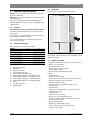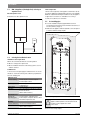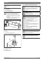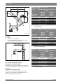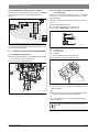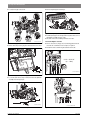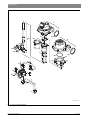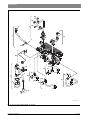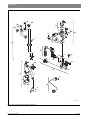
1
WARNING: Improper installation, set-up, modification, operation or maintenance of the heating system can cause personal injury and property damage. Follow these instructions precisely. If you require assistance or further information, contact a trained and certified installer or the gas supply company. WARNING: The operating instructions are part of the technical documents that must be handed over to the owner or operator of the heating system. Explain to the owner or operator how to use the heating system using the operating instructions. Make sure that they are familiar with all required information for the safe and proper operation of the heating system. NOTICE: In Massachusetts, this appliance must be installed by a licensed plumber or gas fitter. These instructions are available in English and French. Please keep these instructions for future reference. 6 720 806 992-00-1O Residential Gas Condensing Boiler Greenstar ZBR16-3A... | ZBR21-3A... | ZBR28-3A... | ZBR35-3A... | ZBR42-3A... | ZWB28-3A... | ZWB35-3A... | ZWB42-3A... 6 720 806 992 (2013/07) CA/US Installation and Service Instructions for Contractors 2 | Contents 5.8.1 Installation of the exhaust and air intake system . . . . . 5.8.2 Approved examples of horizontal and vertical venting installation . . . . . . . . . . . . . . . . . . . . . . . . . . . . . . . . . . . 5.8.3 Vent and combustion air pipe lengths . . . . . . . . . . . . . . 5.9 Testing gas and water connections for leaks . . . . . . . . Contents 1 Key to symbols and safety instructions . . . . . . . . . . . . . . . . . . 3 1.1 Key to symbols . . . . . . . . . . . . . . . . . . . . . . . . . . . . . . . . . 3 1.2 General safety instructions . . . . . . . . . . . . . . . . . . . . . . . 3 6 2 3 4 5 Scope of delivery . . . . . . . . . . . . . . . . . . . . . . . . . . . . . . . . . . . . . 5 2.1 ZBR - Residential boiler for space heating and loading of indirect fired DHW tanks . . . . . . . . . . . . . . . . . . . . . . . . . 5 2.2 ZWB - Residential combi boiler for space heating and DHW generation . . . . . . . . . . . . . . . . . . . . . . . . . . . . . . . . . . . . 6 Information about the appliance . . . . . . . . . . . . . . . . . . . . . . . . 7 3.1 Proper use . . . . . . . . . . . . . . . . . . . . . . . . . . . . . . . . . . . . . 7 3.2 Overview of boiler types . . . . . . . . . . . . . . . . . . . . . . . . . 7 3.3 Rating plate . . . . . . . . . . . . . . . . . . . . . . . . . . . . . . . . . . . . 7 3.4 Appliance description . . . . . . . . . . . . . . . . . . . . . . . . . . . 7 3.5 Accessories . . . . . . . . . . . . . . . . . . . . . . . . . . . . . . . . . . . . 8 3.6 Product dimensions and minimum clearances . . . . . . . . 9 3.7 Appliance layout heating boiler ZBR..-3A . . . . . . . . . . . 10 3.8 Appliance layout combi boiler ZWB..-3A . . . . . . . . . . . 12 3.9 Electrical wiring heating boiler ZBR..-3A . . . . . . . . . . . 14 3.10 Electrical wiring combi boiler ZWB..-3A . . . . . . . . . . . . 16 3.11 Technical data heating boiler ZBR16-3A... . . . . . . . . . . 18 3.12 Technical data heating boiler ZBR21-3A... . . . . . . . . . . 19 3.13 Technical data heating boiler ZBR28-3A... . . . . . . . . . . 20 3.14 Technical data heating boiler ZBR35-3A... . . . . . . . . . . 21 3.15 Technical data heating boiler ZBR42-3A... . . . . . . . . . . 22 3.16 Technical data combi boiler ZWB28-3A... . . . . . . . . . . 23 3.17 Technical data combi boiler ZWB35-3A... . . . . . . . . . . 24 3.18 Technical data combi boiler ZWB42-3A... . . . . . . . . . . 25 3.19 Condensate composition . . . . . . . . . . . . . . . . . . . . . . . . 26 Regulations . . . . . . . . . . . . . . . . . . . . . . . . . . . . . . . . . . . . . . . . . 26 4.1 Compliance with standards and regulations . . . . . . . . . 26 4.2 Operating limits of the boiler . . . . . . . . . . . . . . . . . . . . . 26 4.3 Additional regulations for installation in Massachusetts . . 27 Installation . . . . . . . . . . . . . . . . . . . . . . . . . . . . . . . . . . . . . . . . . . 5.1 Notes on installation and operation . . . . . . . . . . . . . . . . 5.1.1 Notes on installation and operation . . . . . . . . . . . . . . . . 5.1.2 Other important information . . . . . . . . . . . . . . . . . . . . . 5.2 Comparing the size of the integrated expansion vessel . . . . . . . . . . . . . . . . . . . . . . . . . . . . . . . . . . . . . . . 5.3 ZBR..-3A appliances (heating boilers): Selecting an expansion vessel . . . . . . . . . . . . . . . . . . . . . . . . . . . . . . 5.4 Selecting the installation location . . . . . . . . . . . . . . . . . 5.5 Pre-installing pipes . . . . . . . . . . . . . . . . . . . . . . . . . . . . . 5.6 Mounting the appliance . . . . . . . . . . . . . . . . . . . . . . . . . 5.7 Installing a low water cut off (LWCO) . . . . . . . . . . . . . . 5.8 Connecting flue gas accessories . . . . . . . . . . . . . . . . . . 6 720 806 992 (2013/07) 28 28 28 29 29 30 30 30 32 32 33 7 34 38 40 41 Making the electrical connections . . . . . . . . . . . . . . . . . . . . . . 6.1 General notes . . . . . . . . . . . . . . . . . . . . . . . . . . . . . . . . . 6.2 Low voltage electrical connections in the Heatronic boiler control . . . . . . . . . . . . . . . . . . . . . . . . . . . . . . . . . 6.2.1 Open the Heatronic boiler control . . . . . . . . . . . . . . . . . 6.2.2 Connecting the outdoor temperature sensor . . . . . . . . 6.2.3 Connecting the DHW tank temperature sensor (only heating boiler ZBR..-3A) . . . . . . . . . . . . . . . . . . . . . . . . 6.2.4 Connecting additional accessories . . . . . . . . . . . . . . . . 6.3 Electrical connections in the junction box (120 VAC) . 6.3.1 Mounting rails for junction box . . . . . . . . . . . . . . . . . . . 6.3.2 Connecting an external heating zone pump or DHW recirculation pump . . . . . . . . . . . . . . . . . . . . . . . . . . . . 6.3.3 DHW tank loading pump or 3-way valve with spring return (only heating boiler ZBR..-3A) . . . . . . . . . . . . . . 6.3.4 Connecting mains power supply . . . . . . . . . . . . . . . . . . 6.4 Connecting the LWCO device . . . . . . . . . . . . . . . . . . . . 41 41 Commissioning . . . . . . . . . . . . . . . . . . . . . . . . . . . . . . . . . . . . . . 7.1 Before operating the appliance . . . . . . . . . . . . . . . . . . . 7.2 Switching the appliance ON/OFF . . . . . . . . . . . . . . . . . 7.3 Setting up space heating . . . . . . . . . . . . . . . . . . . . . . . . 7.4 Programming the FW 200 heating control unit . . . . . . 7.5 After commissioning . . . . . . . . . . . . . . . . . . . . . . . . . . . 7.6 ZBR..-3A appliances (heating boilers) with DHW tank: Setting the DHW temperature . . . . . . . . . . . . . . . . . . . 7.7 ZWB..-3A appliances (combi boilers): Setting the DHW temperature . . . . . . . . . . . . . . . . . . . 7.8 Setting manual summer mode . . . . . . . . . . . . . . . . . . . . 7.9 Setting frost protection . . . . . . . . . . . . . . . . . . . . . . . . . 7.10 Activating the key pad lock . . . . . . . . . . . . . . . . . . . . . . 47 47 48 48 48 48 42 42 42 42 43 44 44 44 45 45 46 49 49 49 50 50 8 ZBR..-3A appliances (heating boiler) with DHW tank: Thermal disinfection . . . . . . . . . . . . . . . . . . . . . . . . . . . . . . . . . 50 9 Boiler circulator . . . . . . . . . . . . . . . . . . . . . . . . . . . . . . . . . . . . . 51 9.1 Pump anti-seize protection . . . . . . . . . . . . . . . . . . . . . . 51 9.2 Changing the pump curve of the boiler pump . . . . . . . . 51 10 Heatronic boiler control settings . . . . . . . . . . . . . . . . . . . . . . . 10.1 Guideline to service functions . . . . . . . . . . . . . . . . . . . . 10.2 Overview of the service functions . . . . . . . . . . . . . . . . . 10.2.1 First service level (press and hold the service button until it lights up) . . . . . . . . . . . . . . . . . . . . . . . . . . . . . . . 10.2.2 Second service level (at first service level, service button lights up, press ECO button and key pad lock button simultaneously until 8.A appears) . . . . . . . . . . 52 52 52 52 53 Greenstar Key to symbols and safety instructions | 3 10.3 Description of the service functions . . . . . . . . . . . . . . . 53 10.3.1 First service level . . . . . . . . . . . . . . . . . . . . . . . . . . . . . . 53 10.3.2 Second service level . . . . . . . . . . . . . . . . . . . . . . . . . . . 57 17 Commissioning log for the appliance . . . . . . . . . . . . . . . . . . . 75 18 Spare parts . . . . . . . . . . . . . . . . . . . . . . . . . . . . . . . . . . . . . . . . . 77 11 Gas type conversion . . . . . . . . . . . . . . . . . . . . . . . . . . . . . . . . . 11.1 Converting to a different gas type . . . . . . . . . . . . . . . . . 11.2 Installation location higher than 2,000 feet (610 m) above sea level . . . . . . . . . . . . . . . . . . . . . . . . . . . . . . . 11.3 Setting the gas-air ratio (CO2 or O2) . . . . . . . . . . . . . . . 11.4 Dynamic gas pressure test . . . . . . . . . . . . . . . . . . . . . . 59 59 59 60 61 12 Flue gas test . . . . . . . . . . . . . . . . . . . . . . . . . . . . . . . . . . . . . . . . 62 12.1 Emissions test button . . . . . . . . . . . . . . . . . . . . . . . . . . 62 12.2 Measuring CO content of flue gas . . . . . . . . . . . . . . . . . 62 Index . . . . . . . . . . . . . . . . . . . . . . . . . . . . . . . . . . . . . . . . . . . . . . 93 1 Key to symbols and safety instructions 1.1 Key to symbols Warnings Warnings in this document are identified by a warning triangle printed against a grey background. 13 Environmental responsibility/disposal . . . . . . . . . . . . . . . . . . 62 14 Inspection and maintenance . . . . . . . . . . . . . . . . . . . . . . . . . . 14.1 Description of various steps . . . . . . . . . . . . . . . . . . . . . 14.1.1 Calling up the latest fault (service function 6.A) . . . . . 14.1.2 Fresh water filter (only combi boiler ZWB..-3A) . . . . . 14.1.3 Plate type heat exchanger (only combi boiler ZWB..-3A) . . . . . . . . . . . . . . . . . . . . 14.1.4 Checking the electrodes . . . . . . . . . . . . . . . . . . . . . . . . 14.1.5 Burner servicing . . . . . . . . . . . . . . . . . . . . . . . . . . . . . . . 14.1.6 Heat exchanger block inspection and cleaning . . . . . . 14.1.7 Condensate trap cleaning . . . . . . . . . . . . . . . . . . . . . . . 14.1.8 Checking the mixer diaphragm . . . . . . . . . . . . . . . . . . . 14.1.9 Expansion vessel . . . . . . . . . . . . . . . . . . . . . . . . . . . . . . 14.1.10Setting the boiler water pressure . . . . . . . . . . . . . . . . . 14.1.11Testing system water quality . . . . . . . . . . . . . . . . . . . . . 14.1.12Inspecting electrical wiring . . . . . . . . . . . . . . . . . . . . . . 14.2 Checklist for inspection and maintenance . . . . . . . . . . 62 63 63 63 63 64 65 65 67 67 67 67 67 67 68 15 Readings on the display . . . . . . . . . . . . . . . . . . . . . . . . . . . . . . 69 16 Faults . . . . . . . . . . . . . . . . . . . . . . . . . . . . . . . . . . . . . . . . . . . . . . 16.1 Troubleshooting . . . . . . . . . . . . . . . . . . . . . . . . . . . . . . . 16.2 Faults that are shown on the display . . . . . . . . . . . . . . . 16.3 Faults that are not shown on the display . . . . . . . . . . . 16.4 Check sensor values . . . . . . . . . . . . . . . . . . . . . . . . . . . 16.4.1 Outdoor temperature sensor . . . . . . . . . . . . . . . . . . . . . 16.4.2 Additional supply temperature limiter . . . . . . . . . . . . . 16.4.3 Supply temperature sensor, External supply temperature sensor, DHW tank temperature sensor, DHW temperature sensor . . . . . . . . . . . . . . . . . . . . . . . 16.5 Replacement code plug . . . . . . . . . . . . . . . . . . . . . . . . . Greenstar 70 70 71 73 74 74 74 Keywords at the start of a warning indicate the type and seriousness of the ensuing risk if measures to prevent the risk are not taken. The following keywords are defined and can be used in this document: • NOTICE indicates that property damage may occur. • CAUTION indicates that personal injury may occur. • WARNING indicates that severe personal injury may occur. • DANGER indicates that severe personal injury or death may occur. Important information Important information for the proper use of the boiler is also provided in this manual. You will find the information with a symbol shown on the left and bordered by horizontal lines above and below the text. Additional symbols Symbol Explanation ▶ Sequence of steps Cross-reference to other points in this document or to other documents • Listing/list entry – Listing/list entry (2nd level) Table 1 1.2 General safety instructions If you hear gas leaking ▶ Leave the building immediately. ▶ Prevent others from entering the building. ▶ Notify the police and fire department from outside the building. ▶ From outside the building, call the gas supply company and a trained and certified installer or service company. 74 74 6 720 806 992 (2013/07) 4 | Key to symbols and safety instructions If you smell gas ▶ Turn off the gas shut-off valve. ▶ Open windows and doors ▶ Do not touch any electrical switch, telephone, and do not use outlets. ▶ Extinguish all open flames. ▶ Do not smoke! ▶ Do not use lighters! ▶ Warn all occupants of the building that they need to leave the building. ▶ Do not ring doorbells! ▶ Notify the police and fire department from outside the building. ▶ From outside the building, call the gas supply company and a trained and certified installer or service company. If you smell flue gas ▶ Switch off the heating system by shutting off the emergency shut-off switch. ▶ Open windows and doors. ▶ Call a trained and certified installer or service company. DANGER: Risk of fatal injury from failing to consider your own safety! ▶ Never risk your own life. Your own safety must always take the highest priority NOTICE: Risk of appliance damage from improper operation of the boiler! ▶ Only use the boiler for its intended purpose. ▶ Only operate the boiler if it has been installed and maintained per the instructions provided in the Installation Manual. ▶ Do not attempt to operate an appliance if any part of it is not in working order or is damaged. ▶ Use only original spare parts! The use of parts not supplied by the manufacturer may cause damage to the boiler, other property and personal injury. Also, boiler damage caused by the use of unauthorized parts is not covered by the warranty. DANGER: Risk of fire when soldering and brazing! ▶ Take appropriate protective measures when soldering and brazing around combustible and flammable material. NOTICE: ▶ The installation must comply with all applicable national, state, and local codes, rules, and regulations. ▶ The operator is responsible for the operational safety and regulatory compliance of the heating system. ▶ In the Commonwealth of Massachusetts, the appliance must be installed by a licensed plumber or gas fitter. ▶ The venting system must not feed into or route through another air extraction duct. ▶ The venting system must be inspected annually. All parts that show any signs of damage or corrosion must be replaced. ▶ Never close off or reduce the size of the combustion air openings. ▶ The boiler must not be operated until any obstructions have been removed. DANGER: Risk of personal injury or death from explosion! ▶ Work on gas components may only be carried out by a trained and certified installer or service company. ▶ Appliance installation, the connection of gas and vent piping, initial commissioning, electrical connections, and service and maintenance must only be carried out by a trained and certified installer or service company. DANGER: Risk of personal injury or death from fire! ▶ Do not use flammable or combustible material in the boiler room. ▶ It is recommended not to store any items within 16 inches (415mm) of the appliance CAUTION: Appliance damage from contaminated combustion air! ▶ Keep the combustion air free of corrosive substances, e.g. halogenated hydrocarbons from painting operations or beauty salons. ▶ Keep combustion air free from dust and lint, e.g. from laundry or agricultural operations. ▶ If clean room air is not available, fresh outdoor combustion air must be provided DANGER: Risk of personal injury or death from electric shock. ▶ Before removing the front panel, disconnect the heating system from the electrical power supply by shutting off the emergency shutoff switch or the heating system circuit breaker. ▶ It is not enough to switch off the control panel. Power to the panel must be disconnected! Ensure that the power is not restored unintentionally by following proper lock out/tag out procedures. ▶ Only qualified electricians are permitted to carry out electrical work. DANGER: Safety devices! ▶ Never shut off safety valves! ▶ Hot water may escape from the safety valve at any time when the appliance is running. DANGER: Risk of personal injury or death after a flood! ▶ Do not attempt to operate an appliance if any part of it has been under water. ▶ An appliance that was subject to flooding must be replaced. DANGER: Risk of personal injury or death from flue gas poisoning! NOTICE: ▶ Do not install a thermostatic flue gas damper downstream of the draft hood. ▶ Do not tamper with, remove, or attempt to repair the blocked vent switch. ▶ When replacing the blocked vent switch, install the new part in the original location. ▶ A blocked vent switch tripping more than once indicates a problem with the venting system or chimney which must be repaired immediately. ▶ Ensure none of the vent pipes and chimneys are damaged or blocked. ▶ Connect only one appliance to each venting system or chimney. ▶ Upon completion of the installation, these instructions should be handed to the owner and operator of the appliance. ▶ The installer must instruct the owner and operator on the functionality of the components and the proper operation of the boiler and the heating system. ▶ The boiler must be serviced annually including the main burner, ignition burner, the entire venting system, and the combustion air supply. All parts that show any signs of damage or corrosion must be replaced. 6 720 806 992 (2013/07) Greenstar Scope of delivery | 5 2 Scope of delivery 2.1 ZBR - Residential boiler for space heating and loading of indirect fired DHW tanks 1 2 Contents of package 1: 1 Gas condensing boiler 2 Set of documents for appliance 3 Mounting bracket with mounting kit 4 Gas conversion kit 5 Adapter for connection of a LWCO 3 4 5 6 7 8 Contents of package 2: 6 Rail with connection box 7 Flue adapter1) 8 DHW tank temperature sensor (NTC) 9 Hydraulics connection plate with mounting kit 10 External supply temperature sensor (NTC) 11 Outdoor reset control FW 200 with mounting kit and outdoor temperature sensor 12 Set of documents for outdoor reset control FW 200 9 10 11 12 6 720 641 933-22.2O Fig. 1 Scope of delivery heating boiler ZBR..-3A 1) Concentric vent kit available as accessory. Greenstar 6 720 806 992 (2013/07) 6 | Scope of delivery 2.2 ZWB - Residential combi boiler for space heating and DHW generation 1 2 Contents of package 1: [1] Gas condensing boiler [2] Set of documents for appliance [3] Mounting bracket with mounting kit [4] Gas conversion kit [5] Adapter for connection of a LWCO 3 4 5 6 7 Contents of package 2: [6] Rail with connection box [7] Flue adapter1) [8] Hydraulics connection plate with mounting kit [9] External supply temperature sensor (NTC) [10] Outdoor reset control FW 200 with mounting kit and outdoor temperature sensor [11] Set of documents for outdoor reset control FW 200 8 9 10 11 6 720 641 933-04.2O Fig. 2 Scope of delivery combi boiler ZWB..-3A 1) Concentric vent kit available as accessory. 6 720 806 992 (2013/07) Greenstar Information about the appliance | 7 3 3.3 Information about the appliance Rating plate The rating plate is located at the right side of the appliance. ZBR appliances are residential boilers for central heating and loading of an indirect fired DHW tank. ZWB appliances are residential combi boilers for central heating and on demand DHW heating. The appliances comply with South Coast Air Quality Management District (SCAQMD) 2012 requirements: (Type-1) 14 Ng/J NOx (and/or 20 ppm at 3% O2). 3.1 Proper use The Greenstar boiler is not for use in CSD-1 commercial installation. The appliance may only be installed in closed loop hot water central heating systems. Any other purpose is considered improper use. Any resulting damage is excluded from the manufacturer's warranty. The commercial and industrial use of the appliance for generating process heat is not permitted. 3.2 Overview of boiler types Table 2 describes the meaning of the model number: ZBR16-3 ZBR21-3 ZBR28-3 ZBR35-3 ZBR42-3 ZWB28-3 ZWB35-3 ZWB42-3 A A A A A A A A 23 23 23 23 23 23 23 23 Table 2 Appliance types Z W B R 16 21 28 35 42 -3 A 23 Central heating appliance DHW heating Condensing technology Constant temperature control Output up to 54,600 BTU/hr (16 kW) Output and DHW output up to 71,600 BTU/hr (21 kW) Output and DHW output up to 95,500 BTU/hr (28 kW) Output and DHW output up to 119,400 BTU/hr (35 kW) Output and DHW output up to 143,300 BTU/hr (42 kW) Version Fan-supported appliance Natural gas (NG) 6 720 641 933-84.2O Fig. 3 The rating plate contains the appliance output, model number, approval data and serial number. 3.4 • • • • • • • • • • • • • • • • • • • • • • • • • Greenstar Position of the rating plate Appliance description Appliance for wall installation, regardless of chimney and room size Outdoor reset control FW 200 Intelligent boiler pump control Heatronic boiler control with 2-wire BUS Three-speed boiler circulator Automatic air vent (combi boiler ZWB..-3A only) Display Automatic ignition Continuously-controlled output Full protection via the Heatronic with flame rod and solenoid valves No minimum circulating water flow rate required Suitable for radiant floor heating Flue adapter for flue gas and combustion air with test ports Variable speed fan Gas premix burner Temperature sensor and temperature control for space heating Supply temperature sensor Temperature limiter Safety relief valve, pressure gauge Expansion vessel (combi boiler ZWB..-3A only) Connection possibility for DHW tank temperature sensor (NTC) (heating boiler ZBR..-3A only) Flue gas temperature limiter DHW priority (combi boiler ZWB..-3A only) Motorized 3-way valve (combi boiler ZWB..-3A only) Hydraulics connection plate 6 720 806 992 (2013/07) 8 | Information about the appliance 3.5 Accessories Here you will find a list of typical accessories for this appliance. Refer to the Bosch Product Catalog for a complete overview of all available accessories. • FB 100 room control • Modules for system expansions: – ISM2 for solar systems (DHW heating, space heating support, pool heating) – IPM2 for one or two heating zones with pump control and motorized mixing capability – ICM for cascading up to 4 boilers – optional concentric vent kit available for horizontal direct vent terminations 6 720 806 992 (2013/07) Greenstar Information about the appliance | 9 Product dimensions and minimum clearances ≥ 4" * (102 mm) * ≥ 4" * (102 mm) * 17-21/64" (440 mm) 33-15/32" (850 mm) 3-11/32" (85 mm) ≥ 15" (381 mm) 3.6 ≥ 4" ** (102 mm) ** 33-15/16" (862 mm) 1 2 7-7/8" (200 mm) 13-57/64" (353 mm) 1-3/16" (30 mm) 33-27/64" (849 mm) ≥ 4" * (102 mm) * 9-29/64" (240 mm) 3 6 720 641 933-01.2O Fig. 4 [1] [2] [3] (*) (**) Dimensions and minimum clearances (front view, rear view, side view) Appliance jacket Service cover Hydraulics connection plate Zero clearance from combustibles permitted, but 4" (102 mm) recommended for serviceability Distance to door, if mounted inside a closet Greenstar 6 720 806 992 (2013/07) 10 | Information about the appliance 3.7 Appliance layout heating boiler ZBR..-3A 27 28 26 25 29 24 23 22 21 20 30 31 32 19 18 33 17 16 34 35 15 14 36 13 37 38 39 40 1 12 11 10 9 2 3 4 5 41 min 6 7 8 6 720 641 933-02.2O Fig. 5 Appliance layout heating boiler ZBR..-3A 6 720 806 992 (2013/07) Greenstar Information about the appliance | 11 Key to Fig. 5: [1] Heatronic boiler control [2] ON/OFF switch [3] Burner flame indicator [4] Service button [5] Emissions test button [6] Boiler high limit dial [7] Mounting socket for outdoor reset controls [8] DHW thermostat [9] Key pad lock [10] ECO button [11] Reset button [12] Display [13] Condensate trap [14] Test ports for inlet gas pressure [15] Adjustment screw, minimum gas volume [16 ] Maximum gas adjuster [17] Flue gas temperature limiter [18] Combustion air intake [19] Exhaust pipe [20] Boiler supply pipe [21] Connection for optional low water cut off (LWCO) [22] Additional supply temperature limiter [23] Manual air bleeder [24] Gas/air premix chamber [25] Fan [26] Bracket [27] Wall hanging bracket [28] Exhaust pipe [29] Sight glass [30] Set of electrodes [31] Supply temperature sensor [32] Boiler block temperature limiter [33] Inspection and cleanout cover [34] Condensate collector [35] Boiler circulator [36] Pump speed switch [37] Condensate drain hose [38] Drain cock [39] Pressure relief valve (heating zone) [40] Safety relief valve discharge hose [41] Boiler water pressure gauge Greenstar 6 720 806 992 (2013/07) 12 | Information about the appliance 3.8 Appliance layout combi boiler ZWB..-3A 29 30 28 27 26 31 25 24 23 32 33 22 34 21 35 20 19 36 18 37 17 16 38 15 39 40 41 42 43 44 14 13 1 12 11 10 9 2 3 4 5 45 min 6 7 8 6 720 641 933-03.2O Fig. 6 Appliance layout combi boiler ZWB..-3A 6 720 806 992 (2013/07) Greenstar Information about the appliance | 13 Key to Fig. 6: [1] Heatronic boiler control [2] ON/OFF switch [3] Burner flame indicator [4] Service button [5] Emissions test button [6] Boiler high limit dial [7] Mounting socket for outdoor reset controls [8] DHW thermostat [9] Key pad lock [10] ECO button [11] Reset button [12] Display [13] Condensate trap [14] Test ports for inlet gas pressure [15] Adjustment screw, minimum gas volume [16] DHW temperature sensor [17] Plate-type heat exchanger [18] Automatic air vent [19] Maximum gas adjuster [20] Flue gas temperature limiter [21] Combustion air intake [22] Supply pipe [23] Connection for optional low water cut off (LWCO) [24] Additional supply temperature limiter [25] Gas/air premix chamber [26] Expansion vessel [27] Fan [28] Bracket [29] Wall hanging bracket [30] Exhaust pipe [31] Sight glass [32] Set of electrodes [33] Supply temperature sensor [34] Boiler block temperature limiter [35] Inspection and cleanout cover [36] Condensate collector [37] Flow meter [38] 3-way valve [39] Drain cock [40] Condensate drain hose [41] Boiler circulator [42] Pump speed switch [43] Pressure relief valve (heating zone) [44] Safety relief valve discharge hose [45] Boiler water pressure gauge Greenstar 6 720 806 992 (2013/07) 14 | Information about the appliance 3.9 Electrical wiring heating boiler ZBR..-3A 19 20 18 16 6 21 17 23 15 9 22 8 5 5 6 7 24 3 4 4 LP NP 1 2 3 7 B 4 2 2 LS NS L F A 10 11 8 8 L 9 7 1 N N 9 B 4 6 14 25 13 Fig. 7 12 6 720 641 933-23.2O Electrical wiring diagram heating boiler ZBR..-3A 6 720 806 992 (2013/07) Greenstar Information about the appliance | 15 Key to Fig. 7: [1] Ignition transformer [2] Boiler high limit dial [3] 120 VAC connection [4] DHW tank primary pump or 3-way valve 1) [5] External heating pump for unmixed heating circuit (secondary circuit) 2) or DHW recirculation pump 2) [6] Fuse T 6.3 A (120 VAC) [7] DHW thermostat [8] External safety high limit or low water cut off (LWCO) [9] BUS connection, e.g. heating control [10] Room thermostat – dry contact [11] Outdoor temperature sensor [12] Code plug [13] Diagnostic interface [14] ON/OFF switch [15] Gas valve [16] Fan [17] Flue gas temperature limiter [18] Supply temperature sensor [19] Flame rod electrode [20] Ignition electrode [21] Boiler block temperature limiter [22] DHW tank temperature sensor (NTC) [23] Boiler circulator [24] Additional supply temperature limiter [25] External system supply temperature sensor 1) Set the service function 1.F, page 53 2) Set the service function 5.E, page 56 Greenstar 6 720 806 992 (2013/07) 16 | Information about the appliance 3.10 Electrical wiring combi boiler ZWB..-3A 18 19 17 15 6 20 16 22 21 23 14 9 24 8 4 3 4 5 6 7 25 LP NP 1 2 3 6 B 4 2 2 F LS NS A 9 10 6 8 7 L 9 7 1 N 8 B 4 5 13 26 12 Fig. 8 11 6 720 641 933-24.2O Electrical wiring diagram combi boiler ZWB..-3A 6 720 806 992 (2013/07) Greenstar Information about the appliance | 17 Key to Fig. 8: [1] Ignition transformer [2] Boiler high limit dial [3] 120 VAC connection [4] External heating pump for unmixed heating circuit (secondary circuit) 1) or DHW recirculation pump 1) [5] Fuse T 6.3 A (120 VAC) [6] DHW thermostat [7] External safety high limit or low water cut off (LWCO) [8] BUS connection, e.g. heating control [9] Room thermostat – dry contact [10] Outdoor temperature sensor [11] Code plug [12] Diagnostic interface [13] ON/OFF switch [14] Gas valve [15] Fan [16] Flue gas temperature limiter [17] Supply temperature sensor [18] Flame rod electrode [19] Ignition electrode [20] Boiler block temperature limiter [21] DHW temperature sensor [22] Boiler circulator [23] 3-way valve (Space heating/DHW heating) [24] Flow meter (turbine) [25] Additional supply temperature limiter [26] External system supply temperature sensor 1) Set the service function 5.E, page 56 Greenstar 6 720 806 992 (2013/07) 18 | Information about the appliance 3.11 Technical data heating boiler ZBR16-3A... Input/Output Max. input rate 180/79 °F (82/26 °C) Max. output rate 104/86 °F (40/30 °C) Max. output rate 122/86 °F (50/30 °C) Max. output rate 176/140 °F (80/60 °C) Min. input rate 180/79 °F (82/26 °C) Min. output rate 104/86 °F (40/30 °C) Min. output rate 122/86 °F (50/30 °C) Min. output rate 176/140 °F (80/60 °C) Gas connection value Natural Gas – Hs = 1,010 BTU/ft3 (37.3 MJ/m3) Liquid Propane Gas – HD-S = 2,500 BTU/ft3 (93.1 MJ/m3) Permissible inlet gas pressure NG LPG (propane) Flue gas Flue gas mass flow at maximum/minimum nominal output Flue gas temperature 176/140 °F (80/60 °C) at maximum/minimum nominal heat input Flue gas temperature 104/86 °F (40/30 °C) at maximum/minimum nominal heat input CO2 at max. nominal output CO2 at minimum nominal output Condensate Max. condensate quantity (tR = 86 °F (30 °C)) pH level, approx. General Voltage Frequency Max. power consumption (central heating mode) Max. power consumption (Stand-by) Sound pressure level Max. supply temperature Max. permissible operating pressure (PMS) heating Permissible ambient temperature Nominal water capacity (heating) Weight (without packaging) Dimensions, W x H x D Unit BTU/hr (kW) BTU/hr (kW) BTU/hr (kW) BTU/hr (kW) BTU/hr (kW) BTU/hr (kW) BTU/hr (kW) BTU/hr (kW) NG 57,200 (16.8) 54,900 (16.1) 54,300 (15.9) 50,800 (14.9) 12,900 (3.8) 12,600 (3.7) 12,600 (3.7) 11,300 (3.3) LPG (propane) 56,400 (16.5) 55,300 (16.2) 54,600 (16.0) 51,200 (15.0) 21,500 (6.3) 21,500 (6.3) 21,500 (6.3) 19,400 (5.7) ft3/hr (m3/h) ft3/hr (m3/h) 56 (1.6) – – 22 (0.6) in. W.C. (mbar) in. W.C. (mbar) 3.5-10.5" (8.7-26.1) – – 8-13" (19.9-32.3) gps 6.8/1.7 6.7/2.6 °F ( °C) 136/133 (58/56) 136/133 (58/56) °F ( °C) 99/88 (37/31) 99/88 (37/31) % % 9.4 8.6 11.0 10.4 gph (l/h) 0.32 (1.2) 4.8 0.32 (1.2) 4.8 VAC Hz W W dB(A) °F ( °C) psi (bar) °F ( °C) Gal (L) lbs. (kg) inch (mm) 120 120 60 60 205 205 <6 <6 33 33 194 (90) 194 (90) 30 (2.07) 30 (2.07) 32 - 122 (0 - 50) 32 - 122 (0 - 50) 0.925 (3.5) 0.925 (3.5) 103.6 (47) 103.6 (47) 17-21/64" × 33-15/32" × 13-57/64" (440 × 850 × 353) Table 3 Technical data heating boiler ZBR16-3A... 6 720 806 992 (2013/07) Greenstar Information about the appliance | 19 3.12 Technical data heating boiler ZBR21-3A... Input/Output Max. input rate 180/79 °F (82/26 °C) Max. output rate 104/86 °F (40/30 °C) Max. output rate 122/86 °F (50/30 °C) Max. output rate 176/140 °F (80/60 °C) Min. input rate 180/79 °F (82/26 °C) Min. output rate 104/86 °F (40/30 °C) Min. output rate 122/86 °F (50/30 °C) Min. output rate 176/140 °F (80/60 °C) Gas connection value Natural Gas – Hs = 1,010 BTU/ft3 (37.3MJ/m3) Liquid Propane Gas – HD-S = 2,500 BTU/ft3 (93.1MJ/m3) Permissible inlet gas pressure NG LPG (propane) Flue gas Flue gas mass flow at maximum/minimum nominal output Flue gas temperature 176/140 °F (80/60 °C) at maximum/minimum nominal heat input Flue gas temperature 104/86 °F (40/30 °C) at maximum/minimum nominal heat input CO2 at max. nominal output CO2 at minimum nominal output Condensate Max. condensate quantity (tR = 86 °F (30 °C)) pH level, approx. General Voltage Frequency Max. power consumption (central heating mode) Max. power consumption (Stand-by) Sound pressure level Max. supply temperature Max. permissible operating pressure (PMS) heating Permissible ambient temperature Nominal water capacity (heating) Weight (without packaging) Dimensions, W x H x D Unit BTU/hr (kW) BTU/hr (kW) BTU/hr (kW) BTU/hr (kW) BTU/hr (kW) BTU/hr (kW) BTU/hr (kW) BTU/hr (kW) NG 79,200 (23.2) 74,700 (21.9) 74,000 (21.7) 70,300 (20.6) 24,600 (7.2) 23,900 (7.0) 23,900 (7.0) 21,800 (6.4) LPG (propane) 77,500 (22.7) 74,700 (21.9) 74,000 (21.7) 70,300 (20.6) 40,100 (11.7) 39,900 (11.7) 39,600 (11.6) 36,200 (10.6) ft3/hr (m3/h) ft3/hr (m3/h) 78 (2.2) – – 31 (0.9) in. W.C. (mbar) in. W.C. (mbar) 3.5-10.5" (8.7-26.1) – 8-13" (19.9-32.3) gps 9.4/3.2 9.2/4.8 °F ( °C) 145/133 (63/56) 145/133 (63/56) °F ( °C) 115/90 (46/32) 115/90 (46/32) % % 9.4 8.6 11.0 10.4 gph (l/h) 0.5 (1.8) 4.8 0.5 (1.8) 4.8 VAC Hz W W dB(A) °F ( °C) psi (bar) °F ( °C) Gal (L) lbs. (kg) inch (mm) 120 120 60 60 205 205 <6 <6 39 39 194 (90) 194 (90) 30 (2.07) 30 (2.07) 32 - 122 (0 - 50) 32 - 122 (0 - 50) 0.925 (3.5) 0.925 (3.5) 103.6 (47) 103.6 (47) 17-21/64" × 33-15/32" × 13-57/64" (440 × 850 × 353) Table 4 Technical data heating boiler ZBR21-3A... Greenstar 6 720 806 992 (2013/07) 20 | Information about the appliance 3.13 Technical data heating boiler ZBR28-3A... Input/Output Max. input rate 180/79 °F (82/26 °C) Max. output rate 104/86 °F (40/30 °C) Max. output rate 122/86 °F (50/30 °C) Max. output rate 176/140 °F (80/60 °C) Min. input rate 180/79 °F (82/26 °C) Min. output rate 104/86 °F (40/30 °C) Min. output rate 122/86 °F (50/30 °C) Min. output rate 176/140 °F (80/60 °C) Gas connection value Natural Gas – Hs = 1,010 BTU/ft3 (37.3MJ/m3) Liquid Propane Gas – HD-S = 2,500 BTU/ft3 (93.1MJ/m3) Permissible inlet gas pressure NG LPG (propane) Flue gas Flue gas mass flow at maximum/minimum nominal output Flue gas temperature 176/140 °F (80/60 °C) at maximum/minimum nominal heat input Flue gas temperature 104/86 °F (40/30 °C) at maximum/minimum nominal heat input CO2 at max. nominal output CO2 at minimum nominal output Condensate Max. condensate quantity (tR = 86 °F (30 °C)) pH level, approx. General Voltage Frequency Max. power consumption (central heating mode) Max. power consumption (Stand-by) Sound pressure level Max. supply temperature Max. permissible operating pressure (PMS) heating Permissible ambient temperature Nominal water capacity (heating) Weight (without packaging) Dimensions, W x H x D Unit BTU/hr (kW) BTU/hr (kW) BTU/hr (kW) BTU/hr (kW) BTU/hr (kW) BTU/hr (kW) BTU/hr (kW) BTU/hr (kW) NG 100,800 (29.5) 93,800 (27.5) 93,100 (27.3) 89,400 (26.2) 24,600 (7.2) 23,900 (7.0) 23,900 (7.0) 21,800 (6.4) LPG (propane) 98,600 (28.9) 93,800 (27.5) 93,100 (27.3) 89,400 (26.2) 40,100 (11.7) 39,900 (11.7) 39,600 (11.6) 36,200 (10.6) ft3/hr (m3/h) ft3/hr (m3/h) 99 (2.8) – – 39 (1.1) in. W.C. (mbar) in. W.C. (mbar) 3.5-10.5" (8.7-26.1) – 8-13" (19.9-32.3) gps 12.0/3.2 11.6/4.8 °F ( °C) 147/133 (64/56) 147/133 (64/56) °F ( °C) 117/90 (47/32) 117/90 (47/32) % % 9.4 8.6 11.0 10.4 gph (l/h) 0.6 (2.3) 4.8 0.6 (2.3) 4.8 VAC Hz W W dB(A) °F ( °C) psi (bar) °F ( °C) Gal (L) lbs. (kg) inch (mm) 120 120 60 60 205 205 <6 <6 39 39 194 (90) 194 (90) 30 (2.07) 30 (2.07) 32 - 122 (0 - 50) 32 - 122 (0 - 50) 0.925 (3.5) 0.925 (3.5) 103.6 (47) 103.6 (47) 17-21/64" × 33-15/32" × 13-57/64" (440 × 850 × 353) Table 5 Technical data heating boiler ZBR28-3A... 6 720 806 992 (2013/07) Greenstar Information about the appliance | 21 3.14 Technical data heating boiler ZBR35-3A... Input/Output Max. input rate 180/79 °F (82/26 °C) Max. output rate 104/86 °F (40/30 °C) Max. output rate 122/86 °F (50/30 °C) Max. output rate 176/140 °F (80/60 °C) Min. input rate 180/79 °F (82/26 °C) Min. output rate 104/86 °F (40/30 °C) Min. output rate 122/86 °F (50/30 °C) Min. output rate 176/140 °F (80/60 °C) Gas connection value Natural Gas – Hs = 1,010 BTU/ft3 (37.3MJ/m3) Liquid Propane Gas – HD-S = 2,500 BTU/ft3 (93.1MJ/m3) Permissible inlet gas pressure NG LPG (propane) Flue gas Flue gas mass flow at maximum/minimum nominal output Flue gas temperature 176/140 °F (80/60 °C) at maximum/minimum nominal heat input Flue gas temperature 104/86 °F (40/30 °C) at maximum/minimum nominal heat input CO2 at max. nominal output CO2 at minimum nominal output Condensate Max. condensate quantity (tR = 86 °F (30 °C)) pH level, approx. General Voltage Frequency Max. power consumption (central heating mode) Max. power consumption (Stand-by) Sound pressure level Max. supply temperature Max. permissible operating pressure (PMS) heating Permissible ambient temperature Nominal water capacity (heating) Weight (without packaging) Dimensions, W x H x D Unit BTU/hr (kW) BTU/hr (kW) BTU/hr (kW) BTU/hr (kW) BTU/hr (kW) BTU/hr (kW) BTU/hr (kW) BTU/hr (kW) NG 131,900 (38.6) 122,800 (36.0) 121,800 (35.7) 116,700 (34.2) 36,000 (10.5) 35,100 (10.3) 34,800 (10.2) 31,700 (9.3) LPG (propane) 129,100 (37.8) 122,800 (36.0) 121,800 (35.7) 116,700 (34.2) 46,400 (13.6) 46,100 (13.5) 45,700 (13.4) 42,000 (12.3) ft3/hr (m3/h) ft3/hr (m3/h) 130 (3.7) – – 52 (1.5) in. W.C. (mbar) in. W.C. (mbar) 3.5-10.5" (8.7-26.1) – – 8-13" (19.9-32.3) gps 15.7/4.5 15.2/5.6 °F ( °C) 162/135 (72/57) 162/135 (72/57) °F ( °C) 127/91 (53/33) 127/91 (53/33) % % 9.4 8.6 11.0 10.4 gph (l/h) 0.8 (3.1) 4.8 0.8 (3.1) 4.8 VAC Hz W W dB(A) °F ( °C) psi (bar) °F ( °C) Gal (L) lbs. (kg) inch (mm) 120 120 60 60 205 205 <6 <6 44 44 194 (90) 194 (90) 30 (2.07) 30 (2.07) 32 - 122 (0 - 50) 32 - 122 (0 - 50) 0.925 (3.5) 0.925 (3.5) 103.6 (47) 103.6 (47) 17-21/64" × 33-15/32" × 13-57/64" (440 × 850 × 353) Table 6 Technical data heating boiler ZBR35-3A... Greenstar 6 720 806 992 (2013/07) 22 | Information about the appliance 3.15 Technical data heating boiler ZBR42-3A... Input/Output at elevation 0 - 2000 feet (0 - 610 m) Max. input rate 180/79 °F (82/26 °C) Max. output rate 104/86 °F (40/30 °C) Max. output rate 122/86 °F (50/30 °C) Max. output rate 176/140 °F (80/60 °C) Min. input rate 180/79 °F (82/26 °C) Min. output rate 104/86 °F (40/30 °C) Min. output rate 122/86 °F (50/30 °C) Min. output rate 176/140 °F (80/60 °C) Input/Output at elevation 2000 - 4500 feet (611 - 1372 m) above sea level Max. input rate 180/79 °F (82/26 °C) Max. output rate 104/86 °F (40/30 °C) Max. output rate 122/86 °F (50/30 °C) Max. output rate 176/140 °F (80/60 °C) Input/Output at elevation 4500 - 7000 feet (1373 - 2134 m) above sea level Max. input rate 180/79 °F (82/26 °C) Max. output rate 104/86 °F (40/30 °C) Max. output rate 122/86 °F (50/30 °C) Max. output rate 176/140 °F (80/60 °C) Gas connection value Natural Gas – Hs = 1,010 BTU/ft3 (37.3MJ/m3) Liquid Propane Gas – HD-S = 2,500 BTU/ft3 (93.1MJ/m3) Permissible inlet gas pressure NG LPG (propane) Flue gas Flue gas mass flow at maximum/minimum nominal output Flue gas temperature 176/140 °F (80/60 °C) at maximum/minimum nominal heat input Flue gas temperature 104/86 °F (40/30 °C) at maximum/minimum nominal heat input CO2 at max. nominal output CO2 at minimum nominal output Condensate Max. condensate quantity (tR = 86 °F (30 °C)) pH level, approx. General Voltage Frequency Max. power consumption (central heating mode) Max. power consumption (Stand-by) Sound pressure level Max. supply temperature Max. permissible operating pressure (PMS) heating Permissible ambient temperature Nominal water capacity (heating) Weight (without packaging) Dimensions, W x H x D Unit BTU/hr (kW) BTU/hr (kW) BTU/hr (kW) BTU/hr (kW) BTU/hr (kW) BTU/hr (kW) BTU/hr (kW) BTU/hr (kW) NG 151,600 (44.4) 137,500 (40.3) 137,500 (40.3) 134,400 (39.4) 36,000 (10.5) 35,500 (10.4) 35,100 (10.3) 31,700 (9.3) LPG (propane) 148,300 (43.5) 137,500 (40.3) 137,500 (40.3) 134,400 (39.4) 46,400 (13.6) 46,400 (13.6) 46,100 (13.5) 42,000 (12.3) BTU/hr (kW) BTU/hr (kW) BTU/hr (kW) BTU/hr (kW) 136,440 (40.0) 123,750 (36.3) 123,750 (36.3) 120,960 (35.5) 139,402 (40.9) 129,250 (37.9) 129,250 (37.9) 126,336 (37.0) BTU/hr (kW) BTU/hr (kW) BTU/hr (kW) BTU/hr (kW) 125,828 (36.9) 114,125 (33.5) 114,125 (33.5) 111,552 (32.7) 129,021 (37.8) 119,625 (35.1) 119,625 (35.1) 116,928 (34.3) ft3/hr (m3/h) ft3/hr (m3/h) 149 (4.2) – – 59 (1.7) in. W.C. (mbar) 3.5-10.5" (8.7-26.1) in. W.C. (mbar) – – 8-13" (19.9-32.3) gps 18.0/4.5 17.5/5.6 °F ( °C) 171/135 (77/57) 171/135 (77/57) °F ( °C) 133/91 (56/33) 133/91 (56/33) % % 9.4 8.6 11.0 10.4 gph (l/h) 0.9 (3.5) 4.8 0.9 (3.5) 4.8 VAC Hz W W dB(A) °F ( °C) psi (bar) °F ( °C) Gal (L) lbs. (kg) inch (mm) 120 120 60 60 205 205 <6 <6 45 45 194 (90) 194 (90) 30 (2.07) 30 (2.07) 32 - 122 (0 - 50) 32 - 122 (0 - 50) 0.925 (3.5) 0.925 (3.5) 103.6 (47) 103.6 (47) 17-21/64" × 33-15/32" × 13-57/64" (440 × 850 × 353) Table 7 Technical data heating boiler ZBR42-3A... 6 720 806 992 (2013/07) Greenstar Information about the appliance | 23 3.16 Technical data combi boiler ZWB28-3A... Input/Output Max. input rate 180/79 °F (82/26 °C) Max. output rate 104/86 °F (40/30 °C) Max. output rate 122/86 °F (50/30 °C) Max. output rate 176/140 °F (80/60 °C) Output rate domestic hot water (DHW), 113 °F (45 °C) Output rate domestic hot water (DHW), 140 °F (60 °C) Min. input rate 180/79 °F (82/26 °C) Min. output rate 104/86 °F (40/30 °C) Min. output rate 122/86 °F (50/30 °C) Min. output rate 176/140 °F (80/60 °C) Gas connection value Natural Gas – Hs = 1,010 BTU/ft3 (37.3MJ/m3) Liquid Propane Gas – HD-S = 2,500 BTU/ft3 (93.1MJ/m3) Permissible inlet gas pressure NG LPG (propane) Expansion vessel Pre-charge pressure Total contents DHW Max. DHW flow rate Nominal DHW flow rate (at 140 °F (60 °C) outlet temperature) Outlet temperature Max. cold water inlet temperature Max. approved DHW pressure Minimum water pressure Flue gas Flue gas mass flow at maximum/minimum nominal output Flue gas temperature 176/140 °F (80/60 °C) at maximum/minimum nominal heat input Flue gas temperature 104/86 °F (40/30 °C) at maximum/minimum nominal heat input CO2 at max. nominal output CO2 at minimum nominal output Condensate Max. condensate quantity (tR = 86 °F (30 °C)) pH level, approx. General Voltage Frequency Max. power consumption (central heating mode) Max. power consumption (Stand-by) Sound pressure level Max. supply temperature Max. permissible operating pressure (PMS) heating Permissible ambient temperature Nominal water capacity (heating) Weight (without packaging) Dimensions, W x H x D Unit BTU/hr (kW) BTU/hr (kW) BTU/hr (kW) BTU/hr (kW) BTU/hr (kW) BTU/hr (kW) BTU/hr (kW) BTU/hr (kW) BTU/hr (kW) BTU/hr (kW) NG 100,800 (29.5) 93,800 (27.5) 93,100 (27.3) 89,400 (26.2) 93,600 (27.4) 91,400 (26.8) 24,600 (7.2) 23,900 (7.0) 23,900 (7.0) 21,800 (6.4) LPG (propane) 98,600 (28.9) 93,800 (27.5) 93,100 (27.3) 89,400 (26.2) 93,600 (27.4) 91,400 (26.8) 40,100 (11.7) 39,900 (11.7) 39,600 (11.6) 36,200 (10.6) ft3/hr (m3/h) ft3/hr (m3/h) 99 (2.8) – – 39 (1.1) in. W.C. (mbar) in. W.C. (mbar) 3.5-10.5" (8.7-26.1) – – 8-13" (19.9-32.3) psi (bar) Gal (L) 10.9 (0.75) 3.17 (12) 10.9 (0.75) 3.17 (12) gpm (l/min) gpm (l/min) °F ( °C) °F ( °C) psi (bar) psi (bar) 2.64 (10) 2.03 (7.7) 104 - 140 (40 - 60) 140 (60) 150 (10.3) 4.35 (0.3) 2.64 (10) 2.03 (7.7) 104 - 140 (40 - 60) 140 (60) 150 (10.3) 4.35 (0.3) gps 12.0/3.2 11.7/4.9 °F ( °C) 147/133 (64/56) 147/133 (64/56) °F ( °C) 117/90 (47/32) 117/90 (47/32) % % 9.4 8.6 11.0 10.4 gph (l/h) 0.6 (2.3) 4.8 0.6 (2.3) 4.8 VAC Hz W W dB(A) °F ( °C) psi (bar) °F ( °C) Gal (L) lbs. (kg) inch (mm) 120 120 60 60 205 205 <6 <6 39 39 194 (90) 194 (90) 30 (2.07) 30 (2.07) 32 - 122 (0 - 50) 32 - 122 (0 - 50) 0.925 (3.5) 0.925 (3.5) 110.2 (50) 110.2 (50) 17-21/64" × 33-15/32" × 13-57/64" (440 × 850 × 353) Table 8 Technical data combi boiler ZWB28-3A... Greenstar 6 720 806 992 (2013/07) 24 | Information about the appliance 3.17 Technical data combi boiler ZWB35-3A... Input/Output Max. input rate 180/79 °F (82/26 °C) Max. output rate 104/86 °F (40/30 °C) Max. output rate 122/86 °F (50/30 °C) Max. output rate 176/140 °F (80/60 °C) Output rate domestic hot water (DHW), 113 °F (45 °C) Output rate domestic hot water (DHW), 140 °F (60 °C) Min. input rate 180/79 °F (82/26 °C) Min. output rate 104/86 °F (40/30 °C) Min. output rate 122/86 °F (50/30 °C) Min. output rate 176/140 °F (80/60 °C) Gas connection value Natural Gas – Hs = 1,010 BTU/ft3 (37.3MJ/m3) Liquid Propane Gas – HD-S = 2,500 BTU/ft3 (93.1MJ/m3) Permissible inlet gas pressure NG LPG (propane) Expansion vessel Pre-charge pressure Total contents DHW Max. DHW flow rate Nominal DHW flow rate (at 140 °F (60 °C) outlet temperature) Outlet temperature Max. cold water inlet temperature Max. approved DHW pressure Minimum water pressure Flue gas Flue gas mass flow at maximum/minimum nominal output Flue gas temperature 176/140 °F (80/60 °C) at maximum/minimum nominal heat input Flue gas temperature 104/86 °F (40/30 °C) at maximum/minimum nominal heat input CO2 at max. nominal output CO2 at minimum nominal output Condensate Max. condensate quantity (tR = 86 °F (30 °C)) pH level, approx. General Voltage Frequency Max. power consumption (central heating mode) Max. power consumption (Stand-by) Sound pressure level Max. supply temperature Max. permissible operating pressure (PMS) heating Permissible ambient temperature Nominal water capacity (heating) Weight (without packaging) Dimensions, W x H x D Unit BTU/hr (kW) BTU/hr (kW) BTU/hr (kW) BTU/hr (kW) BTU/hr (kW) BTU/hr (kW) BTU/hr (kW) BTU/hr (kW) BTU/hr (kW) BTU/hr (kW) NG 131,900 (38.6) 122,800 (36.0) 121,800 (35.7) 116,700 (34.2) 120,500 (35.3) 118,700 (34.8) 36,000 (10.5) 35,100 (10.3) 34,800 (10.2) 31,700 (9.3) LPG (propane) 129,100 (37.8) 122,800 (36.0) 121,800 (35.7) 116,700 (34.2) 120,500 (35.3) 118,700 (34.8) 46,400 (13.6) 46,100 (13.5) 45,700 (13.4) 42,000 (12.3) ft3/hr (m3/h) ft3/hr (m3/h) 130 (3.7) – – 52 (1.5) in. W.C. (mbar) in. W.C. (mbar) 3.5-10.5" (8.7-26.1) – – 8-13" (19.9-32.3) psi (bar) Gal (L) 10.9 (0.75) 3.17 (12) 10.9 (0.75) 3.17 (12) gpm (l/min) gpm (l/min) °F ( °C) °F ( °C) psi (bar) psi (bar) 3.963 (15) 2.6 (10) 104 - 140 (40 - 60) 140 (60) 150 (10.3) 4.35 (0.3) 3.963 (15) 2.6 (10) 104 - 140 (40 - 60) 140 (60) 150 (10.3) 4.35 (0.3) gps 15.7/4.5 15.2/5.6 °F ( °C) 162/135 (72/57) 162/135 (72/57) °F ( °C) 127/91 (53/33) 127/91 (53/33) % % 9.4 8.6 11.0 10.4 gph (l/h) – 0.8 (3.1) 4.8 0.8 (3.1) 4.8 VAC Hz W W dB(A) °F ( °C) psi (bar) °F ( °C) Gal (L) lbs. (kg) inch (mm) 120 120 60 60 205 205 <6 <6 44 44 194 (90) 194 (90) 30 (2.07) 30 (2.07) 32 - 122 (0 - 50) 32 - 122 (0 - 50) 0.925 (3.5) 0.925 (3.5) 110.2 (50) 110.2 (50) 17-21/64" × 33-15/32" × 13-57/64" (440 × 850 × 353) Table 9 Technical data combi boiler ZWB35-3A... 6 720 806 992 (2013/07) Greenstar Information about the appliance | 25 3.18 Technical data combi boiler ZWB42-3A... Input/Output at elevation 0 - 2000 feet (0 - 610 m) Unit Max. input rate 180/79 °F (82/26 °C) BTU/hr (kW) Max. output rate 104/86 °F (40/30 °C) BTU/hr (kW) Max. output rate 122/86 °F (50/30 °C) BTU/hr (kW) Max. output rate 176/140 °F (80/60 °C) BTU/hr (kW) Output rate domestic hot water (DHW), 113 °F (45 °C) BTU/hr (kW) Output rate domestic hot water (DHW), 140 °F (60 °C) BTU/hr (kW) Min. input rate 180/79 °F (82/26 °C) BTU/hr (kW) Min. output rate 104/86 °F (40/30 °C) BTU/hr (kW) Min. output rate 122/86 °F (50/30 °C) BTU/hr (kW) Min. output rate 176/140 °F (80/60 °C) BTU/hr (kW) Input/Output at elevation 2000 - 4500 feet (611 - 1372 m) above sea level Max. input rate 180/79 °F (82/26 °C) BTU/hr (kW) Max. output rate 104/86 °F (40/30 °C) BTU/hr (kW) Max. output rate 122/86 °F (50/30 °C) BTU/hr (kW) Max. output rate 176/140 °F (80/60 °C) BTU/hr (kW) Output rate domestic hot water (DHW), 113 °F (45 °C) BTU/hr (kW) Output rate domestic hot water (DHW), 140 °F (60 °C) BTU/hr (kW) Input/Output at elevation 4500 - 7000 feet (1373 - 2134 m) above sea level Max. input rate 180/79 °F (82/26 °C) BTU/hr (kW) Max. output rate 104/86 °F (40/30 °C) BTU/hr (kW) Max. output rate 122/86 °F (50/30 °C) BTU/hr (kW) Max. output rate 176/140 °F (80/60 °C) BTU/hr (kW) Output rate domestic hot water (DHW), 113 °F (45 °C) BTU/hr (kW) Output rate domestic hot water (DHW), 140 °F (60 °C) BTU/hr (kW) Gas connection value Natural Gas – Hs = 1,010 BTU/ft3 (37.3MJ/m3) ft3/hr (m3/h) 3 3 Liquid Propane Gas – HD-S = 2,500 BTU/ft (93.1MJ/m ) ft3/hr (m3/h) Permissible inlet gas pressure NG in. W.C. (mbar) LPG (propane) in. W.C. (mbar) Expansion vessel Pre-charge pressure psi (bar) Total contents Gal (L) DHW Max. DHW flow rate gpm (l/min) Nominal DHW flow rate (at 140 °F (60 °C) outlet temperature) gpm (l/min) Outlet temperature °F ( °C) Max. cold water inlet temperature °F ( °C) Max. approved DHW pressure psi (bar) Minimum water pressure psi (bar) Flue gas Flue gas mass flow at maximum/minimum nominal output gps Flue gas temperature 176/140 °F (80/60 °C) at maximum/minimum nominal °F ( °C) heat input Flue gas temperature 104/86 °F (40/30 °C) at maximum/minimum nominal °F ( °C) heat input CO2 at max. nominal output % CO2 at minimum nominal output % NG 151,600 (44.4) 137,500 (40.3) 137,500 (40.3) 134,400 (39.4) 137,500 (40.3) 135,800 (39.8) 36,000 (10.5) 35,500 (10.4) 35,100 (10.3) 31,700 (9.3) LPG (propane) 148,300 (43.5) 137,500 (40.3) 137,500 (40.3) 134,400 (39.4) 137,500 (40.3) 135,800 (39.8) 46,400 (13.6) 46,400 (13.6) 46,100 (13.5) 42,000 (12.3) 136,440 (40.0) 123,750 (36.3) 123,750 (36.3) 120,960 (35.5) 123,750 (36.3) 122,220 (35.8) 139,402 (40.9) 129,250 (37.9) 129,250 (37.9) 126,336 (37.0) 129,250 (37.9) 127,652 (37.4) 125,828 (36.9) 114,125 (33.5) 114,125 (33.5) 111,552 (32.7) 114,125 (33.5) 112,714 (33.0) 129,021 (37.8) 119,625 (35.1) 119,625 (35.1) 116,928 (34.3) 119,625 (35.1) 118,146 (34.6) 149 (4.2) – – 59 (1.7) 3.5-10.5" (8.7-26.1) – – 8-13" (19.9-32.3) 10.9 (0.75) 3.17 (12) 10.9 (0.75) 3.17 (12) 3.963 (15) 3.61 (11.4) 104 - 140 (40 - 60) 140 (60) 150 (10.3) 4.35 (0.3) 3.963 (15) 3.61 (11.4) 104 - 140 (40 - 60) 140 (60) 150 (10.3) 4.35 (0.3) 18.0/4.5 17.5/5.6 171/135 (77/57) 171/135 (77/57) 133/91 (56/33) 133/91 (56/33) 9.4 8.6 11.0 10.4 Table 10 Technical data combi boiler ZWB42-3A... Greenstar 6 720 806 992 (2013/07) 26 | Regulations Input/Output at elevation 0 - 2000 feet (0 - 610 m) Condensate Max. condensate quantity (tR = 86 °F (30 °C)) pH level, approx. General Voltage Frequency Max. power consumption (central heating mode) Max. power consumption (Stand-by) Sound pressure level Max. supply temperature Max. permissible operating pressure (PMS) heating Permissible ambient temperature Nominal water capacity (heating) Weight (without packaging) Unit NG LPG (propane) gph (l/h) – 0.9 (3.5) 4.8 0.9 (3.5) 4.8 VAC Hz W W dB(A) °F ( °C) psi (bar) °F ( °C) Gal (L) lbs. (kg) inch (mm) Dimensions, W x H x D 120 120 60 60 205 205 <6 <6 45 45 194 (90) 194 (90) 30 (2.07) 30 (2.07) 32 - 122 (0 - 50) 32 - 122 (0 - 50) 0.925 (3.5) 0.925 (3.5) 110.2 (50) 110.2 (50) 17-21/64" × 33-15/32" × 13-57/64" (440 × 850 × 353) Table 10 Technical data combi boiler ZWB42-3A... 3.19 Condensate composition 4.1 The condensate volume and ingredients may change with regionally and seasonally varying gas quality and air quality. Typically the following ingredients and concentrations can be expected: The installation must conform to the requirements of the authority having jurisdiction or, in the absence of such requirements, to the latest edition of the National Fuel Gas Code, ANSI Z223.1./NFPA 54. In Canada, installation must be in accordance with the requirements of CAN/CSA B149.1, Natural Gas and Propane Installation Code. Substance Ammonium Lead Cadmium Chrome Halogenated hydrocarbons Hydrocarbons Copper Nickel Mercury Sulfate Zinc Tin Vanadium pH-value Value in ppm (mg/l) 1.2 0.01 0.001 0.005 0.002 0.015 0.028 0.1 0.0001 1 0.015 0.01 0.001 4.8 Table 11 Typical condensate composition 4 Regulations Observe all rules, regulations, standards and guidelines applicable to the installation and operation of this appliance in your country. In the Commonwealth of Massachusetts, this appliance must be installed by a licensed plumber and gas fitter. Valves external to the boiler must be fitted with T-handles and condensate piping must be installed in accordance with the State Plumbing Code. 6 720 806 992 (2013/07) Compliance with standards and regulations This wall mounted condensing gas boiler complies in its design and mode of operation with the American National Standard ANSI Z21.13/ CSA4.9, latest edition for Gas Fired Low Pressure Steam and Hot Water Boilers. Other confirmed approvals and certifications are indicated by labels on the boiler. Where required by the authority having jurisdiction, the installation must conform to the Standard for Controls and Safety Devices for Automatically Fired Boilers, ANSI/ASME CSD-1. Install CO detectors per local regulations. Boiler requires yearly maintenance ( chapter 14, page 62). 4.2 Operating limits of the boiler The heat exchanger has been designed and certified in accordance with the ASME Boiler and Pressure Vessel Code, Section IV. Maximum boiler temperature Maximum operating pressure 194 °F (90 °C) 30 psi (2.07 bar) Table 12 Operating limits The hot water distribution system must comply with all applicable codes and regulations. When replacing an existing boiler, it is important to check the condition of the entire hot water distribution system to ensure safe operation. Common practice calls for inspecting an existing system in its entirety and bringing it up to code. All pipework should be properly cleaned and flushed. Greenstar Regulations | 27 4.3 Additional regulations for installation in Massachusetts (a) For all side wall horizontally vented gas fueled equipment installed in every dwelling, building or structure used in whole or in part for residential purposes, including those owned or operated by the Commonwealth and where the side wall exhaust vent termination is less than seven (7) feet [2150 mm] above finished grade in the area of the venting, including but not limited to decks and porches, the following requirements shall be satisfied: • INSTALLATION OF CARBON MONOXIDE DETECTORS. At the time of installation of the side wall horizontal vented gas fueled equipment, the installing plumber or gasfitter shall observe that a hard wired carbon monoxide detector with an alarm and battery back-up is installed on the floor level where the gas equipment is to be installed. In addition, the installing plumber or gasfitter shall observe that a battery operated or hard wired carbon monoxide detector with an alarm is installed on each additional level of the dwelling, building or structure served by the side wall horizontal vented gas fueled equipment. It shall be the responsibility of the property owner to secure the services of qualified licensed professionals for the installation of hard wired carbon monoxide detectors. – In the event that the side wall horizontally vented gas fueled equipment is installed in a crawl space or an attic, the hard wired carbon monoxide detector with alarm and battery back-up may be installed on the next adjacent floor level. – In the event that the requirements of this subdivision can not be met at the time of completion of installation, the owner shall have a period of thirty (30) days to comply with the above requirements; provided, however, that during said thirty (30) day period, a battery operated carbon monoxide detector with an alarm shall be installed. • APPROVED CARBON MONOXIDE DETECTORS. Each carbon monoxide detector as required in accordance with the above provisions shall comply with NPA 720 and be ANSI/UL 2034 listed and IAS certified. • SIGNAGE. A metal or plastic identification plate shall be permanently mounted to the exterior of the building at a minimum height of eight (8) feet above grade directly in line with the exhaust vent terminal for the horizontally vented gas fueled heating appliance or equipment. The sign shall read, in print size no less than one-half (½) inch in size, “GAS VENT DIRECTLY BELOW. KEEP CLEAR OF ALL OBSTRUCTIONS”. • INSPECTION. The state or local gas inspector of the side wall horizontally vented gas fueled equipment shall not approve the installation unless, upon inspections, the inspector observes carbon monoxide detectors and signage installed in accordance with the provisions of 248 CRM 5.08(2)(a) 1 through 4. instructions provided by the manufacturer for the installation of the equipment and venting shall include: • Detailed instructions for the installation of the venting system or the venting system components; and • A complete parts list for the venting system design or venting system. (d) MANUFACTURERS REQUIREMENTS - GAS EQUIPMENT VENTING SYSTEM NOT PROVIDED. When the manufacturer of Product Approved side wall horizontally vented gas fueled equipment does not provide the parts for the venting of flue gases, but identifies special venting systems, the following requirements shall be satisfied by the manufacturer: • The referenced special venting systems shall be included with the appliance or equipment installation instructions; and • The special venting systems shall be Product Approved by the Board, and the instructions for that system shall include a parts list and detailed installation instructions. (e) A copy of all instructions for all Product Approved side wall horizontally vented gas fueled equipment, all venting instructions, all parts lists for venting instructions, and/or venting design instructions shall remain with the appliance or equipment at the completion of the installation. (b) EXEMPTIONS: The following equipment is exempt from 248 CRM 5.08(2)(a) 1 through 4: • The equipment listed in Chapter 10 entitled “Equipment Not Required To Be Vented” in the most current edition of NFPA 54 as adopted by the board; and • Product Approved side wall horizontally vented gas fueled equipment installed in a room or structure separate from the dwelling, building or structure used in whole or in part for residential purposes. (c) MANUFACTURERS REQUIREMENTS - GAS EQUIPMENT VENTING SYSTEM REQUIRED. When the manufacturer of Product Approved side wall horizontally mounted gas equipment provides a venting system design or venting system components with the equipment, the Greenstar 6 720 806 992 (2013/07) 28 | Installation Recirculation pump/DHW recirculation lines 5 Installation DANGER: Explosion! ▶ Close the gas cock prior to working on the gas train. ▶ Check for gas leaks after carrying out work on the gas train. Installation, power connection, connection on the gas and flue gas side and commissioning must only be carried out by a contractor certified for such work by the state or local jurisdiction or the local gas or power utility. 5.1 Notes on installation and operation When installing and operating the heating system observe the following: • The elevation of the installation location above sea level must be taken into account ( Chapter 11.2). • Follow all local building regulations regarding the installation conditions on site. • The local building regulations regarding air supply and venting systems and the chimney flue connection. • Electrical code requirements for connection to the electrical power supply. • The technical regulations of the gas company regarding the connection of the gas burner to the local gas main. • The regulations and standards relating to the DHW heating system. 5.1.1 Notes on installation and operation Total length DHW/recirculation line 33 ft (10 m) 33 - 66 ft (10 - 20 m) 66 - 98 ft (20 - 30 m) Flow rate 0.66 gpm (2.5 l/min) 0.92 gpm (3.5 l/min) 1.32 gpm (5 l/min) Table 13 Recommended flow rates Use service function 6.d, to determine the current flow rate ( page 56). Electrical connection of the DHW recirculation pump ( page 44). Connect the DHW recirculation line with the cold water inlet as close as possible to the Hydraulics connection plate. Open vented heating systems ▶ Convert open vented heating systems into closed systems. Gravity heating systems ▶ Connect the appliance to the existing piping system via a low-loss header with a sludge separator. Galvanized radiators or pipes. To prevent gas formation: ▶ Do not use galvanized radiators or pipes. Plastic pipework Fill and make-up water for the heating system If using plastic pipework for the heating system (eg.underfloor/radiant heating), the type of pipe that should be used must be oxygen tight. Unsuitable fill and make-up water can result in the heating system scaling up or failing prematurely. Use of a room temperature control Recommended steps for commissioning a new or retrofit boiler installation Water Chemistry Guidelines ▶ Flush the system with clean water. ▶ Isolate the boiler, fill the system with fresh water and a boiler cleaner, run for 30 minutes to 1 hour. Under no circumstances may boiler cleaner be pumped through the boiler. ▶ Thoroughly flush the system with fresh water. Ensure all zones and loops are flushed. ▶ Empty out sediment traps. ▶ Systems containing antifreeze not approved by Bosch, must be completely flushed to ensure no old fluid remains. ▶ Fill the system with fresh water and the proper amount of inhibitor. ▶ Verify the pH is within the proper range. ▶ Add additional inhibitor if pH is not within the proper range. ▶ Check pH annually. ▶ If using antifreeze, fill with approved antifreeze and fresh water. ▶ Always follow the cleaner, antifreeze, or additive manufacturer’s instructions. ▶ Do not mix different manufacturer’s products ▶ Follow manufacturer’s data to determine the anti-freeze ratio for the desired freeze protection temperature. 6 720 806 992 (2013/07) ▶ Do not install thermostatic valves on radiators in the primary room. NOTICE: Primary-secondary piping or a low loss header Radiant floor, panel radiator, multi zone and application systems exceeding 70' (21 m) of 3/4" baseboard at a 20°F delta T and a flow rate of 4.0 gpm plus the necessary supply and return piping, require primarysecondary piping or a low loss header for hydraulic separation of the system from the boiler. NOTICE: Insufficient antifreeze can accelerate corrosion. ▶ Follow manufacturer's instructions on antifreeze concentration. ▶ Frost protection level has to be checked annually during the regular scheduled maintenance of the condensing boiler. NOTICE: System damage! ▶ It is the installer's responsibility to ensure that the heating system is compatible with the boiler type and size installed. ▶ pH-value of the heating water to be kept between 7 and 8.5. Greenstar Installation | 29 The following anti-freeze fluids and concentrations have been approved: Chemical Name Nalco (Varidos) FSK Fernox Alphi 11 Intercool NFP-50 AA Antifrogen N NoBurst AL Concentration 22 - 55 % Observe manufacturer's instructions 0 - 39 % Observe manufacturer's instructions 0 - 55 % • Inspect the sewer pipes for suitability before disposing of untreated boiler condensate into them. • Verify with the local authority that disposing of untreated boiler condensate into public sewer systems is permitted. 5.2 Comparing the size of the integrated expansion vessel Table 14 Anti-freeze The following diagrams allow verifying that the integrated expansion vessel has sufficient capacity for the intended application, or if an additional expansion vessel is needed (not for radiant floor heating). Corrosion inhibitors The following standard conditions were used: The following anti-corrosion agents are approved: • Precharge volume 20% of the rated volume in the expansion vessel • Differential to the safety valve of 7.25 psi (0.5 bar) • Precharge pressure of the expansion vessel equal to the static system height above the boiler • Maximum operating pressure: 30 psi (2.07 bar) Chemical Name Fernox F1 Nalco 77381 Sentinel X 100 Concentration Observe manufacturer's instructions 1-2% 1.1 % Table 15 Corrosion inhibitors 200 ▶ System fluid pH must be maintained between 7 and 8.5 to prevent system damage. ▶ Use only untreated water to fill the system. ▶ Do not use TSP (tri-sodium phosphate). ▶ Do not use fill water treated with salt bedding type exchangers (ion exchanger). ▶ Never introduce non-approved boiler treatment or similar additives. ▶ Only use fill water with a hardness below 7 grains. ▶ Filling with chlorinated water is acceptable if chlorine levels are below 100 ppm. ▶ Do not use inhibitors or other additives unless listed in this document. ▶ Consult a local water treatment specialist for recommendations if any of the above is outside the stated ranges. ▶ When using oxygen permeable PEX, the system must be separated from the boiler by a heat exchanger. ▶ A correctly sized and working expansion vessel must be installed. ▶ Do not exceed the maximum permissible fl ow rate through the boiler. Excessive flow can cause erosion damage to the heat exchanger. ▶ Eliminate System Leaks Continuous addition of make-up water will constantly add oxygen to the system and lead to corrosion. All system leaks must be repaired. 180 Boiler sealer This boiler is not approved for use with boiler sealer. LPG To protect the appliance against high pressure (ANSI/Z223.1/NFPA54 (National fuel gas code) or CAN/CSA B 149.1 (Natural Gas and Propane installation code)): ▶ Install a pressure regulator with a safety valve. 5.1.2 Other important information • The installation of this boiler must comply with all national and local code and regulations. • Only operate this boiler with the combined air/flue system specifically designed and approved for it. • Only use approved venting systems per the manufacturer's instructions. • Do not dispose of untreated boiler condensate in septic systems. Greenstar B I tV/°F 160 140 120 III 100 80 II A 0 20 40 60 80 VA/gal Fig. 9 100 120 6720641933-13.1O Operating capacity of the expansion vessel in °F and gallons 90 tV/°C B I 80 70 60 50 III 40 30 II A 0 75 150 225 VA/l 300 375 450 6720641933-27.1O Fig. 10 Operating capacity of the expansion vessel in °C and liters Key to Fig. 9 and Fig. 10: [I] Precharge pressure 7.25 psi (0.5 bar) (default setting) [II] Precharge pressure 10.9 psi (0.75 bar) [III] Precharge pressure 14.5 psi (1.0 bar) tV Supply temperature in °F ( °C) VA System capacity in gallons (liters) A Within operating capacity of the expansion vessel (left of the relevant curve) B Additional expansion vessel required (right of the relevant curve) ▶ If results are borderline: Determine precise vessel sizes. ▶ If the results are to the right of the curve: Install additional expansion vessel. 6 720 806 992 (2013/07) 30 | Installation 5.3 ZBR..-3A appliances (heating boilers): Selecting an expansion vessel External expansion vessel ▶ Determine size of the expansion vessel. Surface temperature The max. surface temperature of this appliance is below 185 °F (85 °C). According to ANSI/Z223.1/NFPA43 (National fuel gas code) and CAN/ DAS B 149.1 (Natural Gas and Propane installation code), the appliance is approved for zero clearance to combustibles. For servicing a clearance of 4" (102 mm) is recommended. 5.5 Pre-installing pipes ▶ Secure the installation template (supplied with the technical documentation) to the wall; observe the minimum side clearances of 4 inches (102 mm) ( page 9). ▶ Drill holes for the appliance and for the hydraulics connection plate in accordance with the mounting template. ( 17 11/18 in. ) 6 720 641 933-20.2O Fig. 11 Sample installation - expansion vessel 5.4 Selecting the installation location Installation location requirements Observe the current national and local codes and regulations. ▶ Observe country-specific requirements. ▶ Observe installation instructions of the venting system accessories and their clearances. Combustion air To avoid corrosion, keep the supply of combustion air free of corrosive substances; contained in solvents, paints, adhesives, propellants and domestic cleaning agents. Degreasing bath Printing shops Hair salons Household sources Cleaning and degreasing agents Trichloroethylene, tetrachloroethylene, fluorinated hydrocarbons Perchloroethylene, trichloroethylene, methylchloroform Trichloroethylene Aerosol propellants, hydrocarbons containing fluorine and chlorine (difluorodichloromethane) Perchloroethylene, methylchloroform, trichloroethylene, methylene chloride, carbon tetrachloride, hydrochloric acid Workshop Solvents and thinners Various chlorinated hydrocarbons Aerosols Chlorofluorinated hydrocarbons (difluorodichloromethane) Table 16 Corrosive materials 6 720 806 992 (2013/07) 6 720 641 933-45.2O Industrial sources Chemical cleaning Fig. 12 Mounting template NOTICE: For walls with insufficient load capacity, the appliance and the hydraulics connection plate must be mounted on a sheet of plywood or similar reinforcement. ▶ Remove the mounting template. Greenstar Installation | 31 ▶ Secure the hydraulics connection plate and the mounting bracket with the mounting kits supplied. 1 3/8" (35 mm) 1 31/32" (50 mm) 5 1/8" (130 mm) 10 15/64" (260 mm) = = 6 720 641 933-15.1O Fig. 15 Hydraulics connection plate for heating boiler ZBR..-3A (top view) 1 3/16" (30 mm) 7 7/8" (200 mm) = 1 2 = 3 4 5 6 720 641 933-90.1O Fig. 16 Hydraulics connection plate for combi boiler ZWB..-3A (front view) 6 720 641 933-30.1O Fig. 13 Mounting of the hydraulics connection plate and the mounting bracket [1] [2] [3] [4] [5] Heating supply, R 1" NPT DHW, R 3/4" NPT Gas, R 3/4" NPT Cold water, R 3/4" NPT Heating return, R 1" NPT 1 = 2 3 1 3/8" (35 mm) = 5 1/8" (130 mm) 1 31/32" (50 mm) 1 3/16" (30 mm) 7 7/8" (200 mm) 10 15/64" (260 mm) 6 720 641 933-89.1O = = Fig. 14 Hydraulics connection plate for heating boiler ZBR..-3A (front view) [1] [2] [3] Heating supply, R 1" NPT Gas, R 3/4" NPT Heating return, R 1" NPT Greenstar 6 720 641 933-14.1O Fig. 17 Hydraulics connection plate for combi boiler ZWB..-3A (top view) ▶ Determine pipe size for the gas supply. ▶ To fill and drain the system, install a fill and drain valve at the lowest point. 6 720 806 992 (2013/07) 32 | Installation 5.6 Mounting the appliance 5.7 NOTICE: Residue, metal shavings, and contaminants in the piping can damage the appliance. ▶ Flush the piping thoroughly and completely to remove all residue. ▶ Follow the instructions with respect to water quality ( Chapter 5.1, page 28). ▶ Remove packaging, observing all notes and symbols. ▶ On the rating plate, check the identification of the target country and suitability for the gas type supplied by the local gas utility company ( page 10). Installing a low water cut off (LWCO) The boiler is equipped with several sensors that prevent firing or running the boiler in case of low water pressure or low water levels. Nevertheless code may require the installation of a separate low water cut off (LWCO). The boiler is equipped with a dedicated port for installation of a LWCO on the supply pipe inside the boiler cabinet. This location represents the minimum water level for safe operation of the boiler. The LWCO device must be specified for an ambient temperature of 176 °F (80 °C) and a water temperature of 250 °F (121 °C). It needs a dry contact. The following LWCO is approved with the boiler: • Hydrolevel Safgard 1100 The device is available at most Bosch wholesalers. It requires an external 24VAC 20VA transformer provided on site. Removing the cover The cover is secured with two screws against unintentional removal (electrical safety). ▶ Always keep the cover secured with these screws. ▶ Undo screws (step 1). ▶ Lift strap (step 2) and remove cover toward the front (step 3). 2 If other LWCO devices are to be used, they must be installed external to the boiler. The Hydrolevel Safgard 1100 is installed in the supply pipe to the left of the heat exchanger. ▶ Disconnect the boiler from power by shutting off the emergency shutoff switch or disengaging the heating system circuit breaker. ▶ Drain the boiler. ▶ Remove the safety clip from the dummy plug in the supply pipe (step 1). ▶ Pull off the dummy plug (step 2) and place with the boiler documentation. ▶ Ensure the O-ring remains in place on the pipe. ▶ Lubricate the O-ring. 3 2 1 1 6 720 641 933-64.1O Fig. 19 Installing a LWCO device - removing dummy plug 1 6 720 641 933-96.2O Fig. 18 Remove the cover Hanging the appliance ▶ Place flat gaskets on the connections of the hydraulic bracket. ▶ Hang appliance on the mounting bracket. ▶ Tighten the union nuts on the pipe connections. 6 720 806 992 (2013/07) Greenstar Installation | 33 ▶ Screw the LWCO as far as possible into LWCO adapter located in the boiler accessory kit. Follow the Hydrolevel Safgard 1100 instructions. In case of using the twin pipe adaptor: The twin pipe adaptor is supplied with the boiler kit as standard. ▶ Install the vent flange and gasket with the screws enclosed. 3 6 720 641 933-64.1O Fig. 20 Installing a LWCO device - LWCO adapter 2 ▶ Push the adapter with the LWCO onto the pipe (step 1) and secure with the clip (step 2). 1 Ø1 6 720 612 737-01.1O Ø1 > Ø2 Ø2 Fig. 22 Attaching the vent flange and gasket [1] [2] [3] Gasket Vent flange Screws ▶ Insert the flue gas adapter as far as it will go into the vent flange and align it. 1 2 3 2 6 720 641 933-65.3O Fig. 21 Installing a LWCO device – securing with a clip ▶ Connect the wires of the LWCO ( chapter 6.4, page 46). 4 The LWCO is positioned upright for technical reasons. Tests have shown that all air will bleed from the pipe during commissioning and full functionality is established. If fault d3 is displayed when commissioning the boiler, purge the boiler properly and check the boiler water pressure. 5.8 Connecting flue gas accessories Optional vent systems are: • Twin pipe PVC / CPVC 2" / 3" • Twin pipe PP 3" (80 mm) (M&G DuraVent PolyPro GreenVent system) • Concentric PP 3" / 5" (80/125 mm) (M&G DuraVent PolyPro GreenVent system) Greenstar 1 6 720 641 933-85.1O Fig. 23 Flue gas adapter [1] [2] [3] [4] Vent flange Flue gas adapter Combustion air test port Flue gas test ports ▶ Tighten the screws. 6 720 806 992 (2013/07) 34 | Installation 5.8.1 Installation of the exhaust and air intake system To avoid premature wear of the gaskets DO NOT use lubricants. NOTICE: ▶ Vent connectors serving appliances vented by natural draft shall not be connected to any portion of mechanical draft systems operating under positive pressure. In case of open venting: ▶ Use basket on the air intake. In case of concentric venting system: As an alternative to twin pipe venting, a bespoke telescopic concentric vent kit can be obtained as an accessory from Bosch Thermotechnology for a horizontal direct vent wall termination. This vent system can be used for vent lengths of 2 feet to 3 feet (610 mm to 915 mm). For more details on connecting the flue system, refer to the installation instructions for the flue kit. 1 L 2 6 720 806 992-02.1O NOTICE: Burner damage! ▶ Avoid drawing in combustion air excessively loaded with dust or airborne particles. DANGER: ▶ Ensure that the flue pipes and seals are not damaged. ▶ Use only sealing compounds (primer and glue) approved with the vent material. ▶ Never install a barometric nor a thermally controlled vent damper with this boiler. ▶ Connect only one boiler to each flue system or chimney flue. ▶ Do not route the flue system piping through or inside another duct that is used for exhausting air or other flue gases. ▶ The condensate trap must be primed at all times. Failure to do so may allow combustion gases to escape into boiler room. ▶ External insulation on plastic vent pipe is prohibited. Fig. 24 Horizontal venting system (telescopic concentric vent kit) [1] [2] L Intake Exhaust 2 feet to 3 feet (610 mm to 915 mm) Consult local and state codes pertaining to special building code and fire department requirements. Adhere to national code requirements. ▶ Install the concentric vent adaptor with the screws enclosed. Observe the listed maximum lengths of vent system, which are boiler model dependent ( chapter 5.8.3). 2 1 4 3 6 720 806992-01.1O Fig. 25 Installing the concentric vent adaptor [1] [2] [3] [4] Concentric vent adaptor Screws Combustion air test port Flue gas test port 6 720 806 992 (2013/07) Greenstar Installation | 35 Direct vent installations (sealed combustion) For direct vent applications all applicable items below must be met. Vent termination must be at least 1 foot (305 mm) above grade, anticipated snow line or roof surface (Canada 1-1/2 feet (457 mm) minimum) ( fig. 27 [YA], page 37). Vent termination must be at least 7 feet (2135 mm) above a public walkway ( fig. 27 [X5], page 37). Ensure that condensate spilling from the termination does not create a hazard or a nuisance. X Vent termination must be 3 feet (915 mm) above any forced air intake within 10 feet (3 050 mm) ( fig. 27 [1], [YB], page 37). Do not extend exposed vent pipe outside the building beyond recommended distance. Condensate could freeze and block vent pipe. 2 Vent should terminate at least 3 feet (915 mm) away from adjacent walls, inside corners and 5 feet (1 525 mm) below roof overhang ( fig. 27 [X2], [X4], page 37). 1 X It is not recommended to terminate vent above any door or window, condensate can freeze causing ice formations. Do not use chimney as a raceway if another boiler or fireplace is vented into or through chimney. X X 6 720 641 933-19.1O Fig. 26 Vent and combustion air pipe position of a sealed combustion system [1] [2] X Intake Exhaust At least 1 foot (305 mm) The termination shall terminate at least 1 foot (305 mm) below, 1 foot (305 mm) horizontally from or 1 foot (305 mm) above any door, window or gravity air inlet into any building ( fig. 27 [2], [X1], [X3], page 37). Pipe cement/primer ZWB42-3A PVC CPVC ZWB35-3A PP 3" (80 mm) vent or air pipe M&G/ DuraVent PolyPro GreenVent 3"/5" (80/125 mm) concentric M&G/ DuraVent PolyPro GreenVentt ZWB28-3A PP 3" (76 mm) Vent or air pipe and fitting X X X X X X X X X X X X X X X X X X X X X X X X X X X X X X X X X X X X X X ANSI Cat IV X X X X X X X ANSI/ASTM D2564 ANSI/ASTM F493 X X X X X X X X X X X X X X ZBR35-3A PP 2" (50 mm) Vent or air pipe and fitting All PP/PVC/CPVC combustion air and vent pipe materials and fittings must comply with the following and must be UL approved venting material: ZBR28-3A PP Item NOTICE: Damage of 2 inch PVC pipes. ▶ For ZBR42-3A and ZWB42-3A use 2 inch CPVC-pipes or 3 inch pipes. ZBR16-3A Material PVC schedule 40, 80 PVC-DWV CPVC schedule 40, 80 PVC schedule 40, 80 PVC-DWV CPVC schedule 40, 80 The exhaust pipe must be properly supported and pitched a minimum of ¼ inch (6.35 mm) per foot back to the boiler. This allows the condensate to properly drain. ZBR42-3A If multiple boilers are installed in a row, allow at least 1 foot (305 mm) clearance between the vent termination of one and the combustion air intake of the other. All PVC/CPVC vent pipes must be glued, except for the flue gas adapterpipe connection. X X X X X X X X X X X X X X X X X X X X X ANSI Cat IV United states ANSI/ASTM D1785 ANSI/ASTM D2665 ANSI/ASTM F441 ANSI/ASTM D1785 ANSI/ASTM D2665 ANSI/ASTM F441 Canada ANSI Cat IV BH Gas venting systems, ULC S636 1) ANSI Cat IV Table 17 Materials for pipe 1) Components of the certified vent systems must not be interchanged with other vent systems or unlisted pipe fittings. Plastic components, and specified primers and glues of the certified vent system must be from a single system manufacturer and not intermixed with other system manufacturer's vent system parts. Greenstar 6 720 806 992 (2013/07) 36 | Installation Roof terminals Ø 3" / Ø 5" (Ø 76/125 mm) Ø 3" / Ø 5" (Ø 76/125 mm) Ø 3" / Ø 5" (Ø 80/125 mm) Material concentric PVC concentric CPVC concentric PP Supplier IPEX System 636 IPEX System 636 Duravent Part number 196006 197009 3PPS-VK Table 18 Roof terminals Wall terminals Ø 3" (Ø 76 mm) 90 °-elbow with inlet screen Ø 3" (Ø 76 mm) twin pipe termination Ø 3" (Ø 76 mm) single pipe termination Ø 3" / Ø 5" (Ø 80/125 mm) Bosch Greenstar Horizontal Telescopic Terminal Kit Flue System / Materials parallel stainless steel PVC (elbow) stainless steel (screen) PP PP M&G Dura Vent Poly Pro Green Vent System Supplier Flex-L IPEX (elbow) Langly Wire (screen) Duravent Duravent Bosch Part number 46546901 UL-S636 approval (elbow) L2594 (screen) 3PPS-HTP 3PPS-HST 7738003218 Table 19 Wall terminals NOTICE: ▶ DO NOT use cellular core pipe. ▶ DO NOT use PVC when using anti-freeze in the primary circuit of the boiler. Use CPVC or stainless steel only! NOTICE: ▶ Vent terminations must keep the following minimum clearances from electric meters, gas meters, regulators and relief equipment: 4 feet (1220 mm) [Canada 6 feet (1830 mm)] horizontally and in no case above and below, unless a horizontal distance of 4 feet (1220 mm) [Canada 6 feet (1830 mm)] is maintained. 6 720 806 992 (2013/07) Greenstar Installation | 37 3 X1 3 X3 X3 X2 X1 YB X2 X3 X5 X1 X4 3 YA 3 YA 1 2 6 720 641 933-17.1O Fig. 27 Vent and combustion air pipe position Direct vent (sealed combustion): [1] Forced Air Inlet [2] Gravity Air Inlet [3] Exhaust terminal X1 1 foot (305 mm) X2 3 feet (915 mm) X3 1 foot (305 mm) X4 5 feet (1 525 mm) X5 7 feet (2 135 mm) above public walkway YA At least 1 feet (305 mm) above grade and snow line YB Exhaust terminal must be at least 3 feet (915 mm) above forced air inlet within 10 feet (3 050 mm) Fan assisted appliance (non-sealed combustion): [1] Forced Air Inlet [2] Gravity Air Inlet [3] Exhaust terminal X1 1 foot (305 mm) X2 3 feet (915 mm) X3 4 feet (1 220 mm) X4 5 feet (1 525 mm) X5 7 feet (2 135 mm) above public walkway YA At least 1 foot (305 mm) above grade and snow line YB Exhaust terminal must be at least 3 feet (915 mm) above forced air inlet within 10 feet (3 050 mm) Greenstar 6 720 806 992 (2013/07) 38 | Installation NOTICE: ▶ Place pipe supports every 5 feet (1 525 mm) of horizontal and vertical run, beginning with support near boiler. ▶ The condensate must be disposed of in accordance with applicable rules. ▶ Periodic cleaning of the vent terminal and air-intake screens is mandatory. ▶ Avoid locating vent terminals near equipment or building features which can be subject to degradation from exhaust gases. ▶ If multiple boilers are installed in a row, allow at least 1 foot (305 mm) clearance between the vent termination of one and the combustion air intake of the other. ≥ 4" (102 mm) ≥ 12" (305 mm) 5.8.2 Approved examples of horizontal and vertical venting installation 2 1 2 1 6 720 641 933-63.2O 1 Fig. 30 Horizontal venting system (sealed combustion) 2 3 2 6 720 641 933-06.2O Fig. 28 Horizontal venting system (room air only) 1 2 1 2 2 ≥ 4" (102 mm) 6 720 641 933-05.2O Fig. 31 Horizontal venting system (sealed combustion) 6 720 641 933-62.2O Fig. 29 Horizontal venting system (room air only) Key to Fig. 28 and Fig. 29: [1] Intake [2] Exhaust 6 720 806 992 (2013/07) Key to Fig. 30 and Fig. 31: [1] Intake, behind exhaust [2] Exhaust [3] Wall termination Greenstar Installation | 39 Y 1 2 6 720 641 933-09.2O Fig. 32 Vertical venting system (sealed combustion) X X Y Y 1 2 1 2 6 720 641 933-10.1O 6 720 641 933-07.1O Fig. 33 Vertical venting system (room air only) Fig. 34 Vertical venting system (sealed combustion) Key to Fig. 32, Fig. 33 and Fig. 34: [1] Intake [2] Exhaust [3] Concentric termination X Greater than 12 inches (305 mm) Y 12 inches (305 mm) above maximum snow level or at least 24 inches (610 mm) whichever is greater Greenstar 6 720 806 992 (2013/07) 40 | Installation X X Y X Y 1 Installations Fig. 28, 29, 30, 32, 33 and 35 Separate terminations 2" PIPE Maximum straight vent pipe length allowed for Ø 2" pipe ZBR16-3A ZBR35-3A ZBR21-3A ZWB35-3A ZBR28-3A ZBR42-3A Number of 90 ° ZWB28-3A ZWB42-3A elbows used 1 81 ft (24.6 m) 65 ft (19.8 m) 2 76 ft (23.1 m) 57 ft (17.3 m) 3 71 ft (21.6 m) 48 ft (14.6 m) 4 66 ft (20.1 m) 40 ft (12.2 m) 5 61 ft (18.6 m) 32 ft (9.8 m) 6 56 ft (17.1 m) 23 ft (7.0 m) Table 20 Vent and combustion air pipe lengths with 2" diameter and separate terminations 2 6 720 641 933-08.1O Fig. 35 Vertical venting system (sealed combustion) [1] [2] X Y Intake Exhaust Greater than 12 inches (305 mm) 12 inches (305 mm) above maximum snow level or at least 24 inches (610 mm) whichever is greater Installations Fig. 31 Stainless steel wall termination 2" PIPE Maximum straight vent pipe length allowed for Ø 2" pipe ZBR16-3A ZBR35-3A ZBR21-3A ZWB35-3A ZBR28-3A ZBR42-3A Number of 90 ° ZWB28-3A ZWB42-3A elbows used 1 76 ft (23.1 m) 60 ft (18.3 m) 2 71 ft (21.6 m) 52 ft (15.9 m) 3 66 ft (20.1 m) 43 ft (13.1 m) 4 61 ft (18.6 m) 35 ft (10.7 m) 5 56 ft (17.1 m) 27 ft (8.2 m) 6 51 ft (15.6 m) 18 ft (5.5 m) Table 21 Vent and combustion air pipe lengths with 2" diameter and the stainless steel wall termination 1/4" per foot (50 mm per meter) 6 720 641 933-78.1O Fig. 36 Horizontal venting system (telescopic concentric vent kit) 5.8.3 Vent and combustion air pipe lengths 3" (76 mm) Vent and combustion air pipe For all installation situations and for all appliances the maximum vent and combustion air pipe length is 100 feet each, with no more than 8 elbows each. Installations Fig. 34 Concentric termination 2" PIPE Maximum straight vent pipe length allowed for Ø 2" pipe ZBR16-3A ZBR35-3A ZBR21-3A ZWB35-3A ZBR28-3A ZBR42-3A Number of 90 ° ZWB28-3A ZWB42-3A elbows used 1 66 ft (20.1 m) 47 ft (14.3 m) 2 61 ft (18.6 m) 38 ft (11.6 m) 3 56 ft (17.1 m) 30 ft (9.1 m) 4 51 ft (15.6 m) 22 ft (6.7 m) 5 46 ft (14.1 m) 13 ft (4.0 m) 6 41 ft (12.5 m) 5 ft (1.5 m) Table 22 Vent and combustion air pipe lengths with 2" diameter and the concentric termination 2" (50 mm) Vent and combustion air pipe The maximum combined vent and combustion air pipe length ( tab. 20, 21 and 22) depend on the installation situation, the appliance type and the number of elbows used. 6 720 806 992 (2013/07) Greenstar Making the electrical connections | 41 Ø 3" / Ø 5" (Ø 80/125 mm) Concentric venting system The maximum concentric pipe length ( tab. 23) depends on the installation situation, the appliance type and the number of elbows used. Installations Fig. 36 Ø 3" / Ø 5" (Ø 80/125 mm) CONCENTRIC PIPE Maximum straight vent pipe length allowed for Ø 3" / Ø 5" (Ø 80/125 mm) concentric pipe ZBR16-3A ZBR35-3A ZBR21-3A ZWB35-3A ZBR28-3A ZBR42-3A Number of 90 ° ZWB28-3A ZWB42-3A elbows used 1 50 ft (15.2 m) 44 ft (13.4 m) 2 44 ft (13.4 m) 38 ft (11.6 m) 3 38 ft (11.6 m) 32 ft (9.8 m) 4 32 ft (9.8 m) 26 ft (7.9 m) 5 26 ft (7.9 m) 20 ft (6.1 m) 6 20 ft (6.1 m) 14 ft (4.3 m) Table 23 Pipe lengths with Ø 3" / Ø 5" (Ø 80/125 mm) diameter and termination Fitting Equivalent ft 3 6 45 ° elbow 90 ° elbow m 0.91 1.82 Table 24 Concentric pipe friction loss equivalent for fittings Example: • Model: ZBR28-3A • 90 ° elbows used: 2 • 45 ° elbows used: 2 Maximum straight vent pipe allowed: 38ft (11.6 m) 5.9 Testing gas and water connections for leaks NOTICE: System damage! Pressure, control and safety equipment may be damaged by excessive pressure. ▶ When you carry out a leakage test, make sure that no pressure, control or safety equipment is installed that cannot be isolated from the test pressure. ▶ The boiler and its dedicated shutoff valve must be disconnected from the gas supply piping system during any pressure testing of that system at test pressures in excess of 14" W.C. (35 mbar). 6 Making the electrical connections 6.1 General notes DANGER: Risk of electric shock! ▶ Before working on the power supply (120 VAC), disconnect the boiler from the grid by shutting off the emergency shutoff switch or disengaging the heating system circuit breaker. Take measures to prevent accidental reconnection. ▶ It is not sufficient to simply shut off the controls. ▶ Observe all applicable electrical codes and regulations. Electrical components must be installed by a trained and certified electrician and the installation must meet the National Electric Code as well as all applicable local codes and regulations. The boiler must be properly electrically grounded in accordance with the requirements of the authority having jurisdiction or, in the absence of such requirements with the National Electrical Code, ANSI/NFPA 70 and/or the Canadian Electrical Code Part I, CSA C221.1, Electrical Code. Provide a dedicated circuit breaker for the boiler and heating system rated at least 15A. All line voltage wiring must use at least AWG14 size cables. All appliance modulation, control and safety components are tested and pre-wired for use. Observe safety precautions and all rules and regulations required by local code and the National Electric Code. Fuses The appliance is protected with a fuse. It is located on the circuit board ( Fig. 8, page 16). Replacement fuses can be found on the back of the cover ( Fig. 38). Controls and modules For installation and electrical connection of controls and modules, see the installation instructions of the accessory. Water connections ▶ Open the heating supply and return valves and fill the heating system. ▶ Check all connections for leakage (test pressure: Max. 30 psi (2.07 bar) on the pressure gauge). Gas line ▶ Close the gas shutoff valve to protect the gas valve from damage. ▶ Check all connections for leakage (test pressure: Max. 60" W.C. (150 mbar)). ▶ Release pressure. Greenstar 6 720 806 992 (2013/07) 42 | Making the electrical connections 6.2 Low voltage electrical connections in the Heatronic boiler control 6.2.1 Open the Heatronic boiler control ▶ Secure the cable with the strain relief. F A NOTICE: Small pieces of wire can cause shorts and damage the electronics. ▶ Always strip cables away from electronics. ▶ Unhook the clip (step 1) and fold the Heatronic down (step 2). 1 6 720 641 933-35.1O Fig. 39 Electrical wiring outdoor temperature sensor 6.2.3 Connecting the DHW tank temperature sensor (only heating boiler ZBR..-3A) Wire the DHW tank temperature sensor directly to the appliance terminals. The sensor is provided with the appliance. 2 6 720 641 933-72.1O Do not exceed a sensor cable length of 33 feet (10 m). Fig. 37 Fold the Heatronic down ▶ Remove screws (step 1), unhook cable and remove cover (step 2). 1 1 ▶ Punch out plastic insert. ▶ Plug connector into the circuit board. ▶ Insert the cable of the DHW tank temperature sensor. ▶ Secure the cable with the strain relief. 2 1 6 720 641 933-86.1O Fig. 38 Remove the cover 6.2.2 Connecting the outdoor temperature sensor ▶ Connecting the controls automatically establishes the internal communications BUS connection ( see installation instructions for the controls). ▶ Punch out plastic insert. ▶ Connect cable of the outdoor temperature sensor according to Fig. 39. ▶ Insert cable for the outdoor temperature sensor. 6 720 806 992 (2013/07) 6 720 641 933-73.1O Fig. 40 Electrical connections DHW tank temperature sensor Greenstar Making the electrical connections | 43 6.2.4 Connecting additional accessories Connecting the supply temperature sensor (e.g. for low-loss header or system supply pipe) ▶ For splash-proof (IP) strain relief, cut the grommet to match the diameter of the cable. Do not exceed a sensor cable length of 33 feet (10 m). Supply temperature sensor for system supply pipe ( Fig. 43 [2]) must be installed in closest vicinity with boiler supply Tee. 3 4 6 720 641 933-91.1o Fig. 41 Cut off grommets 2 ▶ Feed cable through strain relief and connect accordingly. ▶ Secure the cable on the strain relief. 1 5 ϑ Bosch room controls Connect only Bosch room controls to the internal BUS of this boiler. For installation and electrical connection of the FB 100 remote control, see installation instructions for the remote control. Connecting temperature guard TB 1 (external manual reset high limit or low water cut off (LWCO)) This connection allows the installation of external safety switches. • External manual reset high limit • Low water cut-off (LWCO) • Radiant overheat protection ≤ 4" (102 mm) 6 720 641 933-97.1o Fig. 43 Mounting supply temperature sensor right next to boiler supply [1] [2] [3] [4] [5] System secondary line – supply pipe 1-1/2" Supply temperature sensor for system supply pipe Boiler primary line – supply pipe 1" Boiler primary line – return pipe 1" System secondary line – return pipe 1-1/2" B LP NP B 4 2 LS NS 1 F 9 A 8 7 TB1 ϑ 1 2 C 6 720 641 933-44.1O Fig. 42 Electrical wiring TB1 When the temperature guard trips, central heating and DHW modes are interrupted. 6 720 612 664-25.2O Fig. 44 Electrical wiring of external supply temperature sensor The service function 7.d connection of an external supply temperature sensor is automatically set to 01 ( page 57). Greenstar 6 720 806 992 (2013/07) 44 | Making the electrical connections Connecting Third party room thermostats or zone controls A voltage free (dry contact) third party room thermostat or heat demand from a relay panel can be used to send an ON/OFF signal to the appliance. B LP NP Without accessories the appliance offers the connection of one heating zone pump, one circulator of an unmixed heating circuit, or one DHW recirculation pump. The pump used must have the following connection values: 120 VAC, max. 2 A. B ▶ Route cable from pump to appliance. ▶ Insert cable into the junction box as shown in Fig. 48. ▶ Connect cable to the black plug according to Fig. 47. 4 2 LS NS 6.3.2 Connecting an external heating zone pump or DHW recirculation pump 1 F 9 A 8 7 1 1 2 ϑ 2 3 6 720 641 933-70.1O 4 Fig. 45 Electrical wiring third party room thermostat or zone control To communicate a heat demand the third party room thermostat or zone control must connect pins 2 and 4. 6.3 Electrical connections in the junction box (120 VAC) 6.3.1 Mounting rails for junction box ▶ Hold the rail against the appliance from below (step 1) and fasten with the screws from the outside or inside (step 2). ▶ Loosen junction box from the rail (step 3). Fig. 47 Attach plug (external pump) [1] [2] [3] [4] L (120 VAC, 60 Hz) PE (GND, Ground) N (Neutral) Black plug (in the junction box upon delivery) ▶ Connect black plugs and insert grommet until stop. 2 L 1 L 2 6 720 641 933-41.1O L N PE ite wh ins z Ma /60H 0V 2 1 N PE d re age p r Sto k pum tan N PE ck bla pump atingI II5I03 e II 1 CH ed h I II7I37 70 8 mix for 6 720 641 933-40.1O Fig. 48 Cable connected (external pump) 3 Fig. 46 Mounting rails for junction box 6 720 641 933-42.2O ▶ Use service function 5.E, to set connection to 01 (DHW recirculation pump) ( page 56) -or▶ Use service function 5.E to set connection to 02 (external heating zone pump in an unmixed heating circuit) ( page 56). -or▶ Use service function 5.E to set connection to 03 (external heating pump) ( page 56). The DHW recirculation pump is controlled by the Bosch FW 200. 6 720 806 992 (2013/07) Greenstar Making the electrical connections | 45 6.3.3 DHW tank loading pump or 3-way valve with spring return (only heating boiler ZBR..-3A) The pump used must have the following connection values: 120 VAC, max. 2 A. ▶ Route cable from pump or 3-way valve to appliance. ▶ Insert cable into the junction box as shown in Fig. 50. ▶ Connect cable to the red plug according to Fig. 49. 6.3.4 Connecting mains power supply ▶ Route the power cable (AC 120 V, 60 Hz) from the emergency shutoff switch to the boiler. ▶ Insert cable into the junction box as shown in Fig. 52. ▶ Connect cable to the white plug according to Fig. 51. 1 2 3 1 2 3 4 4 6 720 641 933-36.1O 6 720 641 933-37.1O Fig. 49 Attach plug (external DHW tank loading pump or 3-way valve) [1] [2] [3] [4] L (120 VAC, 60 Hz) PE (GND, Ground) N (Neutral) Red plug (in the junction box upon delivery) Fig. 51 Attach plug (mains power supply) [1] [2] [3] [4] L (120 VAC, 60 Hz) PE (GND, Ground) N (Neutral) White plug (in the junction box upon delivery) ▶ Connect white plugs and insert grommet until stop. ▶ Connect red plugs and insert grommet until stop. L N PE e L whit s z in Ma /60H 0V 12 N PE d L re age p r Sto k pum tan N PE k L blac mp ting III 3 pu ea III 1 50 CH ed h I II7I37 70 8 mix for L L N PE ite wh ins z Ma /60H 0V 12 N PE d re age p r Sto k pum tan N PE ck bla pump atingII II5I03 e I 1 H C ed h I II7I37 70 8 mix for 6 720 641 933-39.1O 6 720 641 933-38.1O Fig. 50 Cable connected (external DHW tank loading pump or 3-way valve) Fig. 52 Cable connected (mains power supply) ▶ Mount junction box on the rail. ▶ Mount the 3-way valve for space heating operation when deenergized, and DHW tank loading when energized. ▶ Use service function 1.F to set pump mode. ( page 53). Greenstar 6 720 806 992 (2013/07) 46 | Making the electrical connections 6.4 Connecting the LWCO device ▶ Connect the leads labeled SWITCH CONTACT (yellow) to the TB1 temperature guard ( Fig 42, page 43) on the Heatronic. NOTICE: System damage or malfunction! ▶ Ensure the air box remains air-tight when routing the LWCO cable to the outside. ▶ Do not route the LWCO cable through the ignition cable grommet as appliance malfunction may occur. 1 2 3 4 5 6 ▶ Punch a hole (maximum diameter 3/16" (5 mm)) through the fan cable grommet (steps 1 – 3) and run the LWCO cable through it. 6 720 641 933-67.1O Ø ≤ 3/16" (~ 5 mm) 1 2 Fig. 54 Wires of a LWCO device with LWCO adapter [1] [2] [3] [4] [5] [6] LWCO device (Hydrolevel Safgard 1100) BOILER GROUND (green) SWITCH CONTACT (yellow) SWITCH CONTACT (yellow) 24V HOT (red) 24V COMMON (white) 3 6 720 641 933-87.1O Fig. 53 Punch a hole in fan cable grommet for LWCO cable ▶ Install a 24VAC 20VA transformer near the boiler. ▶ Follow LWCO manufacturer’s instructions. ▶ Connect the lead labeled BOILER GROUND (green) to pin 2 (center, Fig. 51 [2]) of the white plug in the boiler junction box. ▶ Connect the leads labeled 24V HOT (red) and 24V COMMON (white) to the external 24VAC transformer. 6 720 806 992 (2013/07) Greenstar Commissioning | 47 7 Commissioning 1 3 2 5 4 6 7 9 8 eco reset 10 11 12 18 17 16 15 14 13 19 6 720 641 933-25.1O Fig. 55 Overview of the controls [1] [2] [3] [4] [5] [6] [7] [8] [9] [10] [11] [12] [13] [14] [15] [16] [17] [18] [19] Emissions test button Service button Burner operation indicator lamp ON/OFF power switch Key pad lock ECO button Reset button Display Automatic air vent (ZWB..-3A combi boilers only) Boiler water pressure gauge DHW thermostat Safety relief valve discharge hose Condensate drain hose Heating return pipe Cold water pipe (ZWB..-3A combi boilers only) Gas pipe DHW pipe (ZWB..-3A combi boilers only) Supply pipe Boiler high limit dial Greenstar 7.1 Before operating the appliance NOTICE: Commissioning without being properly filled and purged will damage the appliance. ▶ Only operate this appliance after ensuring there is sufficient water in the boiler and the system. ▶ Adjust the expansion vessel pre-charge pressure to the static head of the heating system ( page 29). ▶ Open radiator and zone valves (as applicable). ▶ Open heating supply and return valves, fill heating system to 14.5 to 21.75 psi (1 - 1.5 bar) and close fill valve. ▶ Bleed all air from the system. ▶ If the boiler water pressure has dropped, fill the heating system again to 14.5 to 21.75 psi (1 to 1.5 bar). ▶ On ZBR..-3A appliances (heating boilers) with a DHW tank, open the cold water supply and open a DHW tap until water runs out. ▶ Verify that the gas type specified on the rating plate is the same as the gas type used. ▶ Open the gas cock. 6 720 806 992 (2013/07) 48 | Commissioning 7.2 Switching the appliance ON/OFF With radiant floor heating, limit the maximum permissible supply temperature as recommended by the manufacturer. Startup ▶ Switch the appliance ON using the ON/OFF switch. The display indicates the supply temperature of the hot water in °F. If necessary, convert to °C ( Service function 0.E: Metric or US customary units, page 57) ▶ In order to set the maximum supply temperature, turn the boiler high limit dial . reset 2 1 4 5 6 max eco 6 720 613 896-05.1O 3 3 3 4 2 2 5 1 Fig. 56 Switching the appliance ON/OFF 4 e 6 1 6 max min max 6 720 641 933-53.2O When the appliance is switched ON for the first time, it performs a once-only purging sequence. This involves the heating zone pump switching on and off at intervals (for approx. 4 minutes). The display shows in alternation with the supply temperature. Fig. 57 Switch on heat If the burner is operating, the burner operation indicator lamp is illuminated. 7.4 Observe the operating instructions for the heating control included in the scope of delivery. There you can read: ▶ How to set the operating mode and the heating curve for outdoor reset controls ▶ How to adjust the room temperature ▶ How to heat economically and comfortably ▶ How the control can be mounted in the boiler or in the living space ▶ Open the automatic vent [9] (only combi boiler ZWB..-3A) and close it again when the purging sequence has finished ( page 47). If the display shows in alternation with the supply temperature, the trap filling function is active ( page 56). Shutdown ▶ Switch appliance OFF using the ON/OFF switch. The display goes out. ▶ If the appliance is taken out of service for a longer period: Observe frost protection ( Section 7.9). 7.3 Programming the FW 200 heating control unit 9 12 h 15 18 6 Setting up space heating 3 24 h 21 Set the maximum supply temperature based on the structure's heat loss on design day. Boiler high limit dial 1 2 3 4 5 6 max Typical supply temperatures approx. 95 °F (35 °C) approx. 109 °F (43 °C) approx. 122 °F (50 °C) approx. 140 °F (60 °C) approx. 153 °F (67 °C) approx. 167 °F (75 °C) approx. 194 °F (90 °C) Sample application Frost protection 6 720 612 660-07.3TT Fig. 58 FW 200 heating control 7.5 Radiant floor heating system Panel radiator system Cast iron radiator system After commissioning ▶ Check flue path for tightness. ▶ Check gas supply dynamic pressure ( page 61). ▶ Check that condensate is being discharged from the condensate hose. If that is not the case, switch the appliance first OFF and then ON again using the ON/OFF switch. That activates the trap filling sequence ( page 56). Repeat the procedure several times until condensate starts running out. ▶ Complete commissioning report ( page 75). Baseboard and convector system Table 25 Typical supply temperatures 6 720 806 992 (2013/07) Greenstar Commissioning | 49 7.6 ZBR..-3A appliances (heating boilers) with DHW tank: Setting the DHW temperature ▶ Set the DHW temperature on the DHW thermostat . The set DHW temperature flashes on the display for 30 seconds. 3 2 1 4 3 2 5 6 max 1 7.7 ZWB..-3A appliances (combi boilers): Setting the DHW temperature ▶ Set the DHW temperature on the DHW thermostat . The set DHW temperature flashes on the display for 30 seconds. reset reset eco eco 3 4 e 2 1 6 4 3 2 5 6 1 max max 4 e 6 max 6 720 641 933-54.1O 6 720 641 933-55.1O Fig. 59 Set the DHW temperature (heating boiler ZBR..-3A) Fig. 60 Set the DHW temperature (combi boiler ZWB..-3A) DHW thermostat min e max DHW thermostat min e max Typical DHW temperatures approx. 59 °F (15 °C) approx. 131 °F (55 °C) approx. 158 °F (70 °C) Table 26 Typical DHW temperatures for heating boiler ZBR..-3A WARNING: Danger of scalding! ▶ In normal operation, it is recommended to limit the DHW temperature to 122 °F (50 °C) to limit the risk of scalding. ▶ Install a tempering valve if running DHW temperatures above 104 °F (40 °C). ▶ Only use temperatures up to 158 °F (70 °C) for thermal disinfection ( page 50). If there is reason for concern for contamination from bacteria such as legionella, consider setting the DHW thermostat to at least “e” (131 °F (55 °C)). This setting ensures an economical and comfortable DHW generation. Consult your local water department or municipality for further information. ECO button The default setting is DHW priority; the ECO button is not lit. In order to switch between DHW tank priority and alternating operation, press the ECO button. • DHW priority First, the DHW tank is heated up to the set temperature. The appliance then goes into heating mode. Therefore, it can happen that space heating is interrupted for a while and the room temperature may drop. DHW tank priority guarantees highest DHW comfort. • Alternating operation The appliance switches between space heating mode and DHW mode. This prevents the room from cooling off too much. Alternating operation guarantees an even room temperature with somewhat less DHW convenience. Typical DHW temperatures approx. 104 °F (40 °C) approx. 122 °F (50 °C) approx. 140 °F (60 °C) Table 27 Typical DHW temperatures for combi boiler ZWB..-3A ECO button Pressing and holding the ECO button until it lights up switches between Comfort mode and Economy mode. • Comfort mode (default setting) The appliance is continually maintained at the set temperature. Consequently, DHW draws are immediate, however the appliance may run even if no DHW is being drawn. • Economy mode, ECO button lights up – DHW is only generated when DHW is drawn. – On demand: Quickly open and close a DHW tap to signal the appliance to heat to the selected temperature. After a short wait DHW will be available. The DHW on demand signal allows maximum gas and water savings. 7.8 Setting manual summer mode In summer mode or warm weather shut down (WWSD), the heating zone pump and consequently central heating are switched off. DHW generation remains active following the DHW program. See also the warm weather shutdown (WWSD) feature in the operating instructions for the heating control included in the scope of delivery. NOTICE: Heating system at risk of freezing. In manual summer mode, only the appliance is protected from freezing. ▶ Observe frost protection measures where there is a risk of frost ( Chapter 7.9). ▶ Make a note of the setting of the boiler high limit dial Greenstar . 6 720 806 992 (2013/07) 50 | ZBR..-3A appliances (heating boiler) with DHW tank: Thermal disinfection ▶ Turn the boiler high limit dial counterclockwise to . reset reset eco eco 4 3 3 5 2 1 e 2 min max 3 6 1 6 4 5 1 max e 2 6 1 6 max max min 6 720 615 065-13.1O 6 720 615 065-17.1O Fig. 61 Summer mode Fig. 64 Key pad lock For further information, see the operating instructions for the heating control included in the scope of delivery. Unlocking the key pad: 7.9 4 3 2 Setting frost protection ▶ Press the key pad lock button until the display shows only the supply temperature. Frost protection of the heating system: ▶ Leave the appliance switched ON; set the boiler high limit to at least 95 °F (35 °C) (position 1, Tab. 25, page 48). eco 5 1 e 2 6 1 6 ▶ Carry out thermal disinfection only outside the normal hours of use, or install a tempering valve. max min max WARNING: Risk of scalding! Hot water can result in severe scalding. 4 3 3 ZBR..-3A appliances (heating boiler) with DHW tank: Thermal disinfection Thermal disinfection covers the DHW system including the taps. For solar DHW tanks, the solar portion of the tank is not covered. reset 2 8 6 720 641 933-68.1O Fig. 62 Frost protection of the heating system -or- If you want to leave the appliance switched OFF: ▶ Mix Bosch-approved anti-freeze into the heating water ( Tab. 14, page 28) and drain the DHW circuit. For further information, see the operating instructions for the heating control included in the scope of delivery. ▶ Close all DHW taps. ▶ Advise occupants of the risk of scalding if no tempering valve is installed. ▶ Set the time and DHW temperature accordingly on the heating control with DHW program. ▶ Set any DHW recirculation pump to continuous operation. ▶ Turn DHW thermostat clockwise to max (approx. 158 °F (70 °C)). reset Frost protection of the DHW tank: eco ▶ Leave the appliance switched ON; set the boiler high limit to at least 95 °F (35 °C) (position 1, Tab. 25, page 48). ▶ Turn the DHW thermostat counterclockwise to min (59 °F (15 °C)). 3 4 2 1 3 2 5 6 max 1 4 e 6 max 6 720 615 065-10.1O reset Fig. 65 Thermal disinfection eco 3 2 1 4 3 5 2 6 max 1 min e 6 max 6 720 641 933-69.1O Fig. 63 Frost protection for the DHW tank 7.10 Activating the key pad lock The key pad lock affects the boiler high limit dial, the DHW thermostat, and all buttons except the ON/OFF switch, emissions test button, and reset button. It can be used to limit unauthorized access to the boiler. ▶ Wait until the maximum temperature has been reached. ▶ Open all DHW taps, from the nearest to the one furthest away, and draw off hot water until it reaches a minimum of 158 °F (70 °C) at all taps for at least 3 minutes. ▶ Reset the DHW thermostat, DHW recirculation pump, and heating control to standard operation. Thermal disinfection can also be carried out automatically and on a regular basis; see operating instructions for the heating control included in the scope of delivery. Activating the key pad lock: ▶ Press the key pad lock button until and the heating supply temperature are alternating on the display. 6 720 806 992 (2013/07) Greenstar Boiler circulator | 51 9 Boiler circulator 9.1 Pump anti-seize protection 25 20 H / ft This function prevents the heating zone pump from seizing up following longer idle periods. The appliance will briefly run the pump at least every 24 hours after its last activation. 4 15 10 3 5 9.2 Changing the pump curve of the boiler pump 2 1 The speed of the boiler pump can be changed using the dial on the pump. 0 0 1 2 25 3 4 5 6 . V / gpm 7 8 7 6 5 15 4 4 10 5 3 2 1 H/m H / ft 20 3 3 2 1 1 0 0 1 2 3 4 5 . V / gpm 6 7 8 6 2 0 0 7 400 800 . V / l/h 1200 1600 6 720 641 933-61.1O Fig. 67 Pump curve of the boiler pump combi boiler ZWB..-3A 5 4 H/m 4 4 3 2 3 1 2 1 0 0 200 400 600 800 1000 1200 1400 1600 . V / l/h Key to Fig. 66 and Fig. 67: [1] Residual head pressure at speed 1 [2] Residual head pressure at speed 2 [3] Residual head pressure at speed 3 (default setting) [4] Head pressure of the boiler pump by itself (at speed 3) H Head pressure in feet of head (m) Circulating water volume in gallons per minute (l/h) V In order to save as much energy as possible and keep any water circulation noises to a minimum, select the lowest possible pump speed. 6 720 641 933-59.1O Fig. 66 Pump curve of the boiler pump heating boiler ZBR..-3A Greenstar 6 720 806 992 (2013/07) 52 | Heatronic boiler control settings 10 ▶ Press and hold the service button until it illuminates. The display shows a code such as 1.A (first service level). Press the ECO button and key pad lock button simultaneously until the code 8.A appears (second service level). ▶ On the second service level, select the service function 8.E and value 00. The appliance restarts with the default settings. Heatronic boiler control settings 10.1 Guideline to service functions The Heatronic allows easy setting and testing of many appliance functions. For an overview of service functions, see Chapter 10.2 on page 52. 3 reset 2 1 eco 3 3 4 2 1 4 2 5 1 6 max 4 5 e 6 max min 6 720 641 933-52.1O Fig. 68 Overview of the controls [1] [2] [3] [4] [5] Emissions test button Service button Display ECO button, service functions “up” Key pad lock, service functions “down” Selecting a service function The service functions are subdivided into two levels: The 1st level includes service functions up to 0.E, the 2nd level includes service functions starting with 8.A. ▶ Press and hold the service button until it illuminates. The display shows a code such as 1.A (first service level). ▶ Repeatedly press the key pad lock button or ECO button to scroll to the desired service function. ▶ Press and release the emissions test button . The emissions test button will light up and the display shows the setting for the selected service function. Adjust Value ▶ Repeatedly press the key pad lock button or ECO button to adjust the value up or down. ▶ Record the value in the commissioning log ( page 75). Saving the value ▶ Press and hold the emissions test button (value saved). until the display shows The unit automatically exits the service level if no button is pressed for 15 minutes. Exiting the service function without saving values ▶ Briefly press the emissions test button . The light of the emissions test button will go out. Restoring factory settings In order to reset all values for the service levels 1 and 2 to the factory setting: 6 720 806 992 (2013/07) 10.2 Overview of the service functions 10.2.1 First service level (press and hold the service button until it lights up) Service function Display 1.A Maximum space heating output 1.b Maximum DHW output 1.E Pump mode for space heating operation 1.F Pump mode 2.A Heating circuit pump lockout time 2.b Maximum supply temperature 2.C Purging function 2.d Thermal disinfection 2.F Operating mode 3.A Automatic anti-cycle function 3.b Set anti-cycle time 3.C Switching differential (hysteresis) 3.d Minimum output (heating and DHW) 3.E Cycle time, keeping DHW hot 3.F Constant DHW period 4.b Maximum heat exchanger temperature 4.d Audible fault warning tone 4.E Appliance type 4.F Condensate trap filling sequence 5.A Reset inspection interval 5.b Fan post purge time 5.E Functionality of black plug in boiler junction box 5.F Set inspection interval 6.A Display the latest fault code 6.b Room temperature control, current voltage, terminal 2 6.C Supply temperature required by outdoor reset control 6.d Current DHW turbine flow rate 7.A Indicator lamp for burner operation / faults 7.b 3-way valve in center position 7.d Connecting an external supply or low-loss header temperature sensor 7.E Building drying function 0.A Do not use this setting! 0.d Altitude adjustment 0.E Metric or US customary units Page 53 53 53 53 54 54 54 54 54 54 55 55 55 55 55 55 55 55 56 56 56 56 56 56 56 56 56 56 57 57 57 57 57 57 Table 28 Service functions, 1st level Greenstar Heatronic boiler control settings | 53 10.2.2 Second service level (at first service level, service button lights up, press ECO button and key pad lock button simultaneously until 8.A appears) Service function Display 8.A Software version 8.b Code plug number 8.C GFA Gas burner control status 8.d GFA Gas burner control fault 8.E Restore boiler to factory settings 8.F Permanent ignition 9.A Constant mode 9.b Current fan speed 9.C Current boiler output 9.d Set fan start speed 9.E Turbine signal delay 9.F Heating zone pump post purge A.b Display DHW temperature A.C Display DHW tank temperature b.F Solar DHW backup heating delay C.d Display current heat demand Page 57 57 57 57 58 58 58 58 58 58 58 58 58 58 58 58 Table 29 Service functions, 2nd level 10.3 Description of the service functions 10.3.1 First service level Service function 1.A: Maximum space heating output Some gas supply companies offer a performance-dependent basic price. The output can be limited in percent between the minimum and maximum nominal output to suit the specific heat demand. Even if the heating output has been limited, the maximum nominal output is still available for DHW generation. ▶ Select service function 1.A. ▶ Select heat output in MBH (kW) and determine associated setting in percent (%). ▶ Enter the setting ( 10.1). ▶ Save the setting ( 10.1). ▶ Record the set heat output in the commissioning log ( page 75). ▶ Exit the service functions. The display returns to the supply temperature. Default setting is the maximum nominal output: 100 (100 %). Service function 1.b: Maximum DHW output The hot water output can be adjusted between the minimum and maximum DHW outputs to suit the heat transfer capacity of the DHW tank coil. ▶ Select service function 1.b. ▶ Select the DHW output in MBH (kW) and determine the associated setting in percent (%). ▶ Enter the setting ( 10.1). ▶ Save the setting ( 10.1). ▶ Record the set DHW output in the commissioning log ( page 75). ▶ Exit the service functions. The display returns to the supply temperature. Default setting is the maximum nominal output: 100 (100 %). Service function 1.E: Pump mode for space heating operation If an outdoor temperature sensor for an outdoor reset control is connected, pump control mode 04 is automatically set. • Pump control mode 00 (automatic mode): The BUS control controls the central heating pump. • Pump control mode 01: For heating systems without control. The supply temperature controls the central heating pump. When there is a demand for heat, the central heating pump and the burner start up. • Pump control mode 02: Do not use. • Pump control mode 03: The central heating pump runs continuously (exceptions: See heating control operating instructions). • Pump control mode 04: Intelligent control of central heating pump in heating systems with outdoor reset control. The heating zone pump is only switched on when needed. Default setting is 00. Service function 1. F: Pump mode (only heating boiler ZBR..-3A) NOTICE: System damage or boiler malfunction! ▶ Never change the setting of this service function on combi boiler ZWB..-3A appliances. Based on this setting, the pump connected to the Heatronic or 3-way valve are controlled according to the configuration of the heating system. The following settings are possible: • Pump mode 00: The appliance is used only as central heating boiler. • Pump mode 01: A 3-way valve for DHW tank loading is connected in boiler circuit before low loss header (see also service function 2.A). • Pump mode 02: Do not use this setting! • Pump mode 03: A DHW tank pump is connected on the system side after the low loss header. In DHW mode, DHW tank loading pump runs. In space heating mode, DHW tank loading pump does not run. Default setting is 03. Greenstar 6 720 806 992 (2013/07) 54 | Heatronic boiler control settings Service function 2.A: Heating circuit pump lockout time (only heating boiler ZBR..-3A) NOTICE: System damage or boiler malfunction! ▶ Never change the setting of this service function on combi boiler ZWB..-3A appliances. This setting is only active if Service function 1. F: Pump mode is set to 01 (3-way valve). Service function 2.d: Thermal disinfection (legionella protection) WARNING: Risk of scalding! Hot water can result in severe scalding. ▶ Carry out thermal disinfection only outside the normal hours of use. ▶ Install a tempering valve if this function is enabled permanently. When this service function is enabled, the DHW is permanently heated to approx. 158 °F (70 °C) if the DHW temperature dial has been turned clockwise to max. During the runtime of an external 3-way valve actuator, the space heating pump is blocked. Select the run time of the 3-way valve actuator between 01 - 24 (10 - 240) seconds according to the manufacturer's documentation. The following settings are possible: • 00: Thermal disinfection not enabled • 01: Thermal disinfection enabled Default setting is 24 (240 seconds). Default setting is 00 (disabled). Service function 2.b: Maximum supply temperature Service function 2.F: Operating mode The values of this service function displayed depend on the setting of the service function 0.E: With this service function, you can temporarily change the appliance's operating mode. Service function 0.E is set to 00 (metric units): • The maximum supply temperature can be adjusted between 35 and 88 (35 - 88 °C). The following settings are possible: • 00: Default mode; the appliance runs according to control settings. • 01: The appliance runs for 15 minutes at minimum output. The display shows 2.F. When this service function is aborted or has been active for 15 minutes, the appliance reverts to default mode. • 02: The appliance runs for 15 minutes at maximum output. The display shows 2.F. When this service function is aborted or has been active for 15 minutes, the appliance reverts to default mode. Service function 0.E is set to 01 (US customary units): • The maximum supply temperature can be adjusted between 96 and 190 (96 - 190 °F). Default setting is 190 (190 °F (88 °C)). Default setting is 00. Service function 2.C: Purging function When the appliance is switched ON for the first time, it performs a once-only purging sequence. This involves the heating zone pump switching on and off at intervals (for approx. 4 minutes). The display shows in alternation with the supply temperature. This service function allows activating the purging function manually, e.g. after servicing. The following settings are possible: • 00: Purging function off • 01: Purging function is switched on and after completion automatically reset to 00 • 02: Purging function is permanently on and is not reset to 00 Service function 3.A: Automatic anti-cycle function If an outdoor reset control is connected, there is no need to adjust this setting on the appliance. The control automatically optimizes the anti-cycle time. Use service function 3.A to set the automatic adaptation of the anti-cycle time. This can be required in case of unfavorably-dimensioned heating systems. Short cycling may increase boiler and system wear and tear, increase emissions, reduce comfort, and should be avoided. With auto-adaptation of the anti-cycle time disabled, the anti-cycle time must be set using service function 3.b ( page 55). The following settings are available: • 00: Automatic adaptation of the anti-cycle time is disabled • 01: Automatic adaptation of the anti-cycle time is enabled Default setting is 00 (switched off). Default setting is 00 for heating boilers ZBR..-3A appliances, otherwise 01. 6 720 806 992 (2013/07) Greenstar Heatronic boiler control settings | 55 Service function 3.b: Set anti-cycle time Only if the automatic anti-cycle time is disabled (service function 3.A) will this function be active. If an outdoor reset control is connected, there is no need to adjust this setting on the appliance. The control automatically optimizes the anti-cycle time. The anti-cycle time can be set from 00 to 15 (0 to 15 minutes). With 00, the anti-cycle lock is switched off. The shortest possible switching interval is 1 minute (recommended for single zone or forced air heating systems). Service function 3.F: Constant DHW period (only combi boiler ZWB..-3A) NOTICE: System damage or boiler malfunction! ▶ Never change the setting of this service function on heating boiler ZBR..-3A appliances. The constant DHW period specifies how long the space heating mode remains disabled after DHW is drawn. The duration for keeping DHW hot can be set from 00 to 30 (0 to 30 minutes). Default setting is 01 (1 minute). Default setting is 03. Service function 3.C: Switching differential Only if the automatic anti-cycle time is disabled (service function 3.A) will this function be active. If an outdoor reset control is connected, there is no need to adjust this setting on the appliance. The control automatically optimizes this setting. The switching differential is the permitted boiler differential from the target supply temperature. It can be set in increments of 1 °F (0.5 °C). The minimum supply temperature is 95 °F (35 °C). Service function 0.E is set to 00 (metric units): • You can set the switching differential between 00 and 30 (0 - 30 °C). Service function 0.E is set to 01 (US-customary units): • You can set the switching differential between 00 and 54 (0 - 54 °F). Default setting is 18 (18 °F (10 °C)). Service function 3.d: Minimum output (heating and DHW) The output for heating and DHW can be set to any level in percent between the minimum and maximum nominal output. The default setting is the minimum nominal output (heating and DHW) and varies according to appliance. Service function 4.b: Maximum heat exchanger temperature (only combi boiler ZWB..-3A) NOTICE: System damage or boiler malfunction! ▶ Never change the setting of this service function on heating boiler ZBR..-3A appliances. This function can be used to reduce limestone built-up in the heat exchanger, which increases with temperature. The maximum heat exchanger temperature can be set in steps of 1 °F (0.5 °C). Service function 0.E is set to 00 (metric units): • The maximum temperature for keeping the heat exchanger hot can be set from 40 to 65 (40 to 65 °C). Service function 0.E is set to 01 (US-customary units): • The maximum temperature for keeping the heat exchanger hot can be set from 104 to 150 (104 to 150 °F). Default setting is 140 (140 °F (60 °C)). Service function 4.d: Audible fault warning tone The appliance can be set to sound an audible alarm to alert the operator of a fault present. The audible warning tone can be deactivated with the service function 4.d. • 00: Warning tone off • 01: Warning tone on Default setting is 01 (ON). Service function 3.E: Cycle time, keeping DHW hot (only combi boiler ZWB..-3A) NOTICE: System damage or boiler malfunction! ▶ Never change the setting of this service function on heating boiler ZBR..-3A appliances. This service function is only active in comfort mode. It specifies the time from completion of preheating or DHW demand until the next time the plate-type heat exchanger is heated up. This prevents the plate-type heat exchanger from overheating. Service function 4.E: Appliance type This service function displays the appliance type detected. Possible displays are: • 00: Central heating only • 01: Combi appliance • 02: DHW tank temperature sensor (NTC) connected to Heatronic. • 03: DHW tank thermostat connected to Heatronic. • 04: Stratified DHW tank • 05: Tank with NTC return The cycle time can be set from 20 to 60 minutes. Default setting is 20 (20 minutes). Greenstar 6 720 806 992 (2013/07) 56 | Heatronic boiler control settings Service function 4.F: Condensate trap filling sequence DANGER: Risk of flue gas poisoning! If the condensate trap is not filled, flue gas may escape from the dry trap. ▶ Only deactivate the trap filling sequence for servicing purposes. ▶ When servicing is complete, reactivate the trap filling function. Service function 5.F: Set inspection interval This service function allows setting the number of months after which the 'service due' reminder appears on the display alternating with the supply temperature. The number of months can be set from 00 - 72 (0 to 72 months). Default setting is 00 (disabled). If U0 appears on the display, the function was already set via the FW200 control. The trap filling sequence ensures that the condensate trap is filled after initial installation or after a longer downtime of the appliance. The trap filling sequence is activated if: • The appliance is switched OFF using the ON/OFF switch • The burner has not been in use for at least 28 days • You are switching between summer and winter mode Service function 6.A: Display the latest fault code The next time there is a demand for heat in central heating or hot water mode, the appliance is held at low output for 15 minutes. The trap filling sequence remains active until the appliance has completed 15 minutes of operation at low output. The display shows in alternation with the supply temperature. Service function 6.b: Room temperature control, current voltage, terminal 2 The following settings are available: • 00: Condensate trap filling sequence is off. • 01: Trap filling program at the lowest output. • 02: Trap filling sequence at set minimum output. Default setting is 01. Use this service function to display the most recent fault code. The current voltage of the analog control at terminal 2 is displayed. Possible displays are: • 00 - 24: 0 V to 24 V in increments of 1 V Service function 6.C: Supply temperature required by outdoor reset control This service function allows displaying the current target supply temperature set by the outdoor reset control. Service function 5.A: Reset inspection interval This function enables resetting the indication on the display after completing inspection/servicing of the appliance. Default setting 00. Service function 5.b: Fan post purge time Service function 6.d: Current DHW turbine flow rate (only combi boiler ZWB..-3A) NOTICE: System damage or boiler malfunction! ▶ Never change the setting of this service function on heating boiler ZBR..-3A appliances. This service function allows setting the time the fan purges after the burner is shut off. The current flow rate of the DHW turbine is displayed. The post purge time can be set from 01 to 18 (10 - 180 seconds). Service function 0.E is set to 00 (metric units): • 0.0. - 99.9.: 0.0 to 99 l/min in increments of 0.1 l/min Default setting is 03 (30 seconds). Service function 5.E: Functionality of black plug in boiler junction box With this service function you can set the functionality of the black plug in the boiler junction box ( page 45). The following settings are possible: • 00: Off - black connector in junction box is disabled (120VAC output deactivated). • 01: DHW recirculation pump enabled - see FW200 instructions on how to set a recirculation pump program. • 02: External heating zone pump in heating circuit without 3-way valve controlled by FW 200. • 03: External heating zone pump in heating circuit without mixer controlled by Heatronic running in parallel with boiler pump in central heating mode Service function 0.E is set to 01 (US-customary units): • 0.0. - 99.9.: 0.0 to 99 gpm in increments of 0.1 gpm Service function 7.A: Indicator lamp for burner operation / faults With this service function you can activate and deactivate the indicator lamp for burner operation (continuously illuminated) and faults (flashing). The following settings are possible: • 00: Off • 01: On (burner operation) and flashing (fault present) Default setting is 00. Default setting is 03. 6 720 806 992 (2013/07) Greenstar Heatronic boiler control settings | 57 Service function 7.b: 3-way valve in center position Service function 0.d: Altitude adjustment After the value 01 has been saved, the 3-way valve moves to the center position. This allows draining the system completely and removing the motor easily. Input and output rates are reduced at higher altitudes due to thin air with reduced oxygen levels. When you exit this service function, the appliance returns to setting 00. Service function 7.d: Connecting an external supply or low-loss header temperature sensor Presence of an external supply or low loss header temperature sensor is automatically detected by default; you do not need to change any settings. If a sensor is disconnected, change the setting back to the default setting 00. The following settings are available: • 00: Once-only automatic detection of a sensor • 01: External supply temperature sensor connected to Heatronic. • 02: External supply temperature sensor connected to IPM2. Default setting is 00. Service function 7.E: Building drying function This service function allows you to start and stop the building drying function. Never confuse the appliance building drying function with the slab drying function of the outdoor reset control FW200. ZBR42-3A... and ZWB42-3A... appliances are derated at 3 % per 1000 feet (305 m). ZBR16-3A..., ZBR21-3A..., ZBR28-3A..., ZBR35-3A..., ZWB28-3A... and ZWB35-3A... appliances offer altitude adjustment which compensates for the effects of thin air, and are therefore NOT derated up to 6000 feet (1829 m). Above 6000 feet (1829 m) a rate of 3 % per 1000 feet (305 m) applies. This service function is used to adjust the fan speed for high altitude operation. The following settings are available: • 00: Normal • 01: Medium • 02: High Setting 00 01 02 Elevation above sea level 0 ft – 2,000 ft (0 m – 610 m) 2,001 ft – 4,500 ft (611 m – 1 372 m) above 4,500 ft (1 372 m) Table 30 Altitude adjustment (service function 0.d) Default setting is 00. Service function 0.E: Metric or US customary units With this service function you can set if Metric or US customary units are displayed on the boiler. The following settings are available: • 00: °C, l/min (metric units) • 01: °F, gpm (US-customary units) When the building drying function is on, you cannot adjust the appliance gas settings. Default setting is 01. 10.3.2 Second service level The following settings are available: • 00: Off • 01: Heating operation only in accordance with the appliance or control setting, i.e. all other heat demands are blocked. Default setting is 00. Service function 0.A: Do not use this setting! Default setting is 00 (disabled). Service function 8.A: Software version The current software version is displayed. Service function 8.b: Code plug number The last four digits of the code plug number are shown. The code plug determines the appliance functions. If the appliance has been converted from natural gas to LPG (or vice versa), the code plug must be replaced. Service function 8.C: GFA Gas burner control unit status Internal parameter. If you are on the line with Bosch Technical Support you may be asked for this number. Service function 8.d: GFA Gas burner control unit fault Internal parameter. Greenstar 6 720 806 992 (2013/07) 58 | Heatronic boiler control settings Service function 8.E: Restore boiler to factory settings This function allows resetting all parameters of the boiler including all service functions to their factory settings. ▶ Press and hold the service button until it illuminates. The display shows a code such as 1.A (first service level). ▶ Press and hold ECO button and key pad lock button simultaneously until a service function, e.g. 8.A, is displayed (second service level). ▶ Repeatedly press the key pad lock button or ECO button until service function 8.E is displayed. ▶ Press and release the emissions test button . The emissions test button lights up and the display shows 00. ▶ Press and hold the emissions test button until the display shows . All settings are reset and the appliance restarts with the default settings. ▶ Reset altered service functions to the settings recorded in the commissioning log ( page 75). Default setting is 50. Service function 9.E: Turbine signal delay (only combi boiler ZWB..-3A) NOTICE: System damage or boiler malfunction! ▶ Never change the setting of this service function on heating boiler ZBR..-3A appliances. This service function allows setting a time delay to prevent the appliance starting up as a result of transient pressure spikes in the water supply. Through spontaneous pressure change in the water supply, the flow meter (turbine) can signal that DHW is being drawn and cause the burner to come on unnecessarily. The turbine signal delay can be set from 02 to 08 (0.5 seconds to 2 seconds) in increments of 0.25 seconds. Default setting is 04 (1 second). Service function 8.F: Permanent ignition Service function 9.F: Heating zone pump post purge NOTICE: Ignition transformer damage. ▶ Never leave this function on for longer than 2 minutes at a time. This function enables permanent ignition without gas supply to test the performance of all ignition related components. The following settings are available: • 00: Off • 01: On Default setting is 00. Service function 9.A: Constant mode This function sets one operating mode permanently ( Service function 2.F: Operating mode, page 54). The following settings are available: • 00: Default mode: the appliance runs according to control settings. • 01: The appliance runs permanently at minimum output. The display shows 9.A. • 02: The appliance runs permanently at maximum output. The display shows 9.A. This service function allows setting a pump post purge time after the end of the heat demand from the external control. The pump post purge time can be set from 01 to 10 (1 to 10 minutes). Default setting is 03. Service function A.b: Display DHW temperature This service function allows displaying the current DHW temperature. Service function A.C: Display DHW tank temperature This service function allows displaying the temperature of the DHW tank temperature sensor. Service function b.F: Solar DHW backup heating delay (only combi boiler ZWB..-3A) For systems with a solar thermal DHW tank in series before the DHW line of the combi boiler. DHW heating by the boiler will be suppressed expecting that solar thermal DHW will reach the hot water temperature sensor prior eliminating the need to run the boiler. Set the heating delay in accordance with system conditions. Default setting is 00. Service function 9.b: Current fan speed This service function allows you to display the current fan speed in revolutions per second (1/s). Service function 9.C: Current boiler output If this setting is enabled, the DHW demand signal is no longer available page 49. The start delay can be set between 00 to 50 (0 to 50 seconds) in increments of 1 second. Default setting is 00. This service function displays the current boiler output (in percent (%)). Service function C.d: Display current heat demand Service function 9.d: Set fan start speed At higher elevations the boiler fan may need to spin faster upon startup to ensure reliable ignition every time. The start speed of the boiler fan can be set from 45 to 77 revolutions per second (1/s). 6 720 806 992 (2013/07) Available displays are: • 00: No heat demand • 01: Space heating demand present • 02: DHW heat demand present Greenstar Gas type conversion | 59 11 Gas type conversion DANGER: Personal injury and property damage ▶ This conversion shall only be performed by a trained and certified installer in accordance with the manufacturer‘s instructions and all applicable codes and requirements of the authority having jurisdiction. ▶ If the information in these instructions is not followed exactly, or the installation, adjustment, modification, operation or maintenance is carried out by an unqualified person, a fire, explosion or generation of large amounts of carbon monoxide may result causing property damage, personal injury or loss of life. ▶ Before carrying out electrical work: Disconnect the installation from the power supply at the emergency shutoff switch or by disengaging the heating system circuit breaker. Take measures to prevent accidental reconnection. ▶ The installer is responsible for the proper conversion of this appliance. ▶ The conversion is not complete until the operation of the converted appliance is checked as specified in these instructions. ▶ Replace the code plug in the Heatronic with the code plug from the gas conversion kit. 6 720 641 933-57.1O Fig. 69 Replacing the code plug ▶ Affix the gas type label from the gas conversion kit to the appliance. The gas-air ratio must always be set on the basis of a CO2 or O2 reading taken at maximum nominal output and minimum nominal output using an electronic flue gas analyzer. Adjustment to different flue systems using throttle discs or baffles is not necessary. 6 720 641 933-58.2O NG • Appliances are set at the factory to Wobbe index 1,333 BTU/ft3 (49.6 MJ/m3) at 60 °F (15 °C), 30" Hg (1016 hPa) and 7.0" W.C. (17.4 mbar) gas supply pressure and sealed. Fig. 70 Affixing the gas type label ▶ Always adjust the gas-air ratio (CO2 or O2, Section 11.3) after converting to a different gas type and measure the CO content of the flue gas ( Section 12). 11.1 Converting to a different gas type DANGER: Explosion! ▶ Close the gas cock prior to working on the gas train. ▶ Check for gas leaks after carrying out work on the gas train. A gas conversion kit is included in the scope of delivery. ▶ Fold the Heatronic down. ▶ Check the number on the code plug from the gas conversion kit (Code plug number table 43, page 74). 11.2 Installation location higher than 2,000 feet (610 m) above sea level Input and output rates are reduced at higher altitudes due to thin air with reduced oxygen levels. ZBR42-3A... and ZWB42-3A... appliances are derated at 3 % per 1000 feet (305 m). ZBR16-3A..., ZBR21-3A..., ZBR28-3A..., ZBR35-3A..., ZWB28-3A... and ZWB35-3A appliances offer altitude adjustment which compensates for the effects of thin air, and are therefore NOT derated up to 6000 feet (1829 m). Above 6000 feet (1829 m) a rate of 3 % per 1000 feet (305 m) applies. The Bosch Greenstar boiler is factory set for installation below 2000 feet (610 m) above sea level. ▶ Correction of the fan speed curve of the burner: Use service function 0.d to adjust the elevation setting ( page 57). Greenstar 6 720 806 992 (2013/07) 60 | Gas type conversion 11.3 Setting the gas-air ratio (CO2 or O2) ▶ Adjust the gas throttle to match the CO2 or O2 level for maximum nominal output according to table 31. ▶ Switch the appliance OFF using the ON/OFF switch. ▶ Remove the cover ( page 32). ▶ Switch the appliance ON using the ON/OFF switch. ▶ Open one of the flue gas test ports. 6 7 2 0 6 1 2 6 5 9 -3 8 .1 R Fig. 73 Set CO2 or O2 level for maximum nominal output Gas type NG LPG (propane) Maximum nominal output CO2 O2 9.4 % 4.0 % 11.0 % 4.2 % Minimum nominal output CO2 O2 8.6 % 5.5 % 10.4% 5.1 % Table 31 CO2 or O2 values at maximum and minimum nominal output 6 720 641 933-79.1O Fig. 71 Open one of the flue gas test ports ▶ Insert the probe approx. 2-3/4 inches (70 mm) into the test port and seal around it. ▶ Press and hold the emissions test button until it lights up. The display shows the supply temperature alternating with = maximum set output in heating mode. ▶ Briefly press the emissions test button . The display shows the supply temperature in alternation with = maximum nominal output. ▶ Measure the CO2 or O2 level and the CO content of the flue gas ( Section 12). ▶ Briefly press the emissions test button . The display shows the supply temperature in alternation with = minimum nominal output. ▶ Measure the CO2 or O2 level and the CO content of the flue gas ( Section 12). ▶ Remove the sealed screw ( Fig. 74, [3]) from gas valve adjustment screw ( Fig. 74, [2]) and set CO2 or O2 level for minimum nominal output. 3 ▶ On the gas throttle, break the seal at the slot and remove the cap. 2 2 . 1 6 720 641 933-81.1O 1 . Fig. 74 Set CO2 or O2 level for minimum nominal output 6 7 2 0 6 1 2 6 5 9 -3 7 .1 R Fig. 72 Remove seal from the gas throttle 6 720 806 992 (2013/07) ▶ Re-check settings at maximum and minimum nominal output and readjust if necessary. ▶ Repeatedly press the emissions test button until the light goes out. The display returns to the supply temperature. ▶ Record the CO2 or O2 levels and the CO content of the flue gas in the commissioning log. ▶ Reinstall the screw ( Fig. 74, [3]) to cover the gas valve adjustment screw. Greenstar Gas type conversion | 61 ▶ Remove flue gas probe and close the flue gas test port properly. 11.4 Dynamic gas pressure test ▶ Switch the appliance OFF and close the gas shut-off valve. ▶ Loosen the screw in the test port for gas inlet pressure ( Fig. 74, [1]) and connect a pressure gauge ( Fig. 76). 6 720 614 090-34.2O Fig. 76 Dynamic gas pressure test port 6 720 641 933-80.1O Fig. 75 Close flue gas test ports ▶ Turn on the gas cock and switch the appliance ON. ▶ Press and hold the emissions test button until it lights up. The display shows the supply temperature alternating with = maximum set output in heating mode. ▶ Briefly press the emissions test button . The display shows the supply temperature in alternation with = maximum nominal output. ▶ Check the required inlet gas pressure according to table 32. Gas type NG LPG (propane) Nominal pressure " W.C. (mbar) 7 (17.4) 11 (27.4) Permissible pressure range for maximum nominal output " W.C. (mbar) 3.5-10.5 (8.7-26.1) 8-13 (19.9-32.3) Table 32 Inlet gas pressure Do not operate the appliance if the measured value is below or above these values. Determine the cause and eliminate the fault. If this is not possible, block the appliance on the gas side and notify the gas supplier. ▶ Repeatedly press the emissions test button until the light goes out. The display returns to the supply temperature. ▶ Switch the appliance OFF, turn off the gas cock, remove the pressure gauge and tighten the screw in the test port for gas inlet pressure. ▶ Reinstall the cover. Greenstar 6 720 806 992 (2013/07) 62 | Flue gas test 12 Flue gas test 13 12.1 Emissions test button The following appliance outputs can be selected by pressing the emissions test button until it lights up: 3 4 2 1 3 5 6 max Packaging eco All packaging materials used are environmentally-friendly and recyclable. Old appliances e 6 1 min Environmental responsibility is one of the fundamental company policies of the Bosch Group. We regard quality of performance, economy and environmental responsibility as equal objectives. Environmental protection laws and regulations are strictly adhered to. To protect the environment, we use the best possible technology and materials taking into account economic points of view. reset 4 2 Environmental responsibility/disposal max 6 720 641 933-51.1O Old appliances contain resources that must be submitted for recycling. The components are easy to separate and the plastics are marked. This allows the various components to be sorted for appropriate recycling or disposal. Fig. 77 Press the emissions test button • = Maximum set output in heating mode ( Maximum heating output, page 53) • = Maximum nominal output • = Minimum nominal output You have 15 minutes to complete the tests. After that, the appliance returns to default mode. 12.2 Measuring CO content of flue gas 14 Inspection and maintenance Regular service and maintenance are recommended for a long service life of the appliance, for efficient and economical operation, and to keep the environmental impact as low as possible. Owners/operators are encouraged to sign a service and maintenance contract with a trained and certified installer for annual servicing and maintenance of the boiler. DANGER: Explosion! ▶ Close the gas cock prior to working on the gas train. ▶ Check for gas leaks after carrying out work on the gas train. Use a multiport flue gas probe for the measurements. ▶ Open one of the flue gas test ports ( Fig. 71). ▶ Insert the flue gas probe approx. 2-3/4 inches (70 mm) into the test port and seal around it. ▶ Press the emissions test button to select = maximum nominal output. ▶ Measure the CO levels. DANGER: Risk of flue gas poisoning. The CO level in the flue gas must be below 200 ppm (air free). ▶ If 9.4 Vol.%1) CO2 and a CO level under 200 ppm (af) can not be achieved due to the gas supplied, use a lower CO2 level with CO emissions under 200 ppm (af) instead. 1) 9.4 Vol.% with NG and 11.0 Vol.% with LPG (propane) ▶ Repeatedly press the emissions test button until the light goes out. The display returns to the supply temperature. ▶ Remove flue gas probe and close the flue gas test port properly ( Fig. 75). 6 720 806 992 (2013/07) DANGER: Risk of flue gas poisoning. ▶ Check for leaks after carrying out work on the venting system. DANGER: Risk of electric shock! ▶ Always disconnect the appliance from the mains power before performing any work. Disconnect the emergency shutoff switch or disengage the heating system circuit breaker. Take measures to prevent accidental reconnection. NOTICE: Insufficient antifreeze can accelerate corrosion. ▶ Frost protection level has to be checked annually during the regular scheduled maintenance of the condensing boiler. Greenstar Inspection and maintenance | 63 Heat exchanger NOTICE: Damage to the coating of the heat exchanger. ▶ Cleaning of the heat exchanger should not be necessary until five years after the initial commissioning. ▶ Only use a Bosch cleaning blade or Bosch cleaning brush ( page 92). ▶ Only clean heat exchanger if soiling is clearly visible. 14.1.2 Fresh water filter (only combi boiler ZWB..-3A) ▶ Close cold water tap. ▶ Depressurize the cold water pipe. ▶ To access the filter remove the safety clip (step 1), pull out the pipe (step 2), and remove the filter from the pipe (step 3). ▶ If necessary, clean with plastic brush under running water. 1 Heatronic boiler control In case of a component defect, a fault is shown on the display. The Heatronic boiler control monitors all safety and control components. NOTICE: The Heatronic boiler control can be damaged by leaking water. ▶ Cover the Heatronic prior to working on water filled components. 3 Notes on installation and operation 2 An overview of the faults can be found on page 71. 6 720 641 933-92.1o • The following analytical tools are needed for service and maintenance: – Electronic flue gas analyzer for CO2, O2, CO, and flue gas temperature – Pressure gauge 0 to 12 inches W.C. (0 to 30 mbar) – pH Test strips – Glycol tester of antifreeze is being used • Special tools are not required. • Approved lubricants are: – For parts touched by water: Unisilkon L 641 (part-# 8 709 918 413 0) – or fittings: HFt 1 v 5 (part-# 8 709 918 010 0). ▶ Use part-# 8 719 918 658 0 as heat conducting paste. ▶ Use only genuine Bosch spare parts. ▶ Request spare parts ( Section 18, page 77). ▶ Replace removed gaskets and O-rings with new ones. Fig. 78 Filter in fresh water pipe (combi boiler ZWB..-3A only) 14.1.3 Plate type heat exchanger (only combi boiler ZWB..-3A) If the DHW output on the combi boiler is significantly reduced: ▶ Check filter in the cold water pipe for contamination ( Fig. 63). ▶ Depressurize the appliance. ▶ Remove plate type heat exchanger and replace -or▶ Descale with descaling agent approved for stainless steel (Grade 316-1.4401). To remove the plate type heat exchanger: ▶ Unplug electrical connections. ▶ Remove hose from safety relief valve. After the inspection/maintenance ▶ Re-tighten all loosened threaded connections. ▶ Restart the appliance ( page 47). ▶ Check all connections for leaks. ▶ Check the gas-air ratio and adjust if necessary ( page 60). 14.1 Description of various steps 14.1.1 Calling up the latest fault (service function 6.A) ▶ Select service function 6.A ( page 56). An overview of the faults can be found on page 71. 6 720 641 933-46.2O Fig. 79 Unplugging electrical connections / removing hose from safety relief valve Greenstar 6 720 806 992 (2013/07) 64 | Inspection and maintenance ▶ Loosen/remove pipe connections. ▶ Remove the plate type heat exchanger. 6 720 641 933-50.2O Fig. 83 Removing the plate heat exchanger ▶ Install new plate type heat exchanger with new gaskets and reconnect the hydraulic assembly in reverse order. ▶ Check all connections used during maintenance for leaks. 6 720 641 933-47.2O Fig. 80 Removing pipe connections ▶ Remove the boiler pressure gauge from the Heatronic boiler control. 14.1.4 Checking the electrodes ▶ Remove electrode set ( page 10 / 12) including gasket and check electrodes for contamination; clean or replace, if required. ▶ Reinstall electrode set with new gaskets and check for leaks. 2-1/4 + 3/4 ft.-lbf. (3 + 1 Nm) 6720641933-28.1O 6 720 641 933-48.2O Fig. 84 Reinstalling the electrode set Fig. 81 Removing the boiler pressure gauge ▶ Loosen the quick releases (steps 1 and 2) and remove the hydraulic assembly in its entirety (step 3). 2. Gas/Gaz? 1. 1. 3. Fig. 82 Removing the hydraulic assembly 6 720 806 992 (2013/07) 6 720 641 933-49.2O 6 720 613 354-02.2O Fig. 85 Check for leaks Greenstar Inspection and maintenance | 65 14.1.5 Burner servicing 14.1.6 Heat exchanger block inspection and cleaning DANGER: Fire danger! ▶ Only operate the burner while installed in a boiler. ▶ Remove burner lid (steps 1 - 4). 4 2 NOTICE: Damage to the coating of the heat exchanger. ▶ Cleaning of the heat exchanger should not be necessary until five years after the initial commissioning. ▶ Only use a Bosch cleaning blade and Bosch cleaning brush ( page 92). ▶ Only clean heat exchanger in case if soiling is clearly visible. ▶ Remove the inspection cover ( page 10) and any sheet metal insert below, if installed. ▶ Determine degree of soiling of the heat exchanger through visual inspection. If mechanical cleaning is required: 3 For cleaning the heat exchanger, Bosch offers the service accessory kit which includes main heat exchanger gaskets, the heat exchanger brush and heat exchanger cleaning blade (part-# 7719001998). 1 ▶ Remove the condensate trap (steps 1 and 2) and place a suitable container underneath. 6 720 641 933-95.1o Fig. 86 Removing the burner cover ▶ Remove burner and clean its components. 1 2 6 720 641 933-93.1o 7 181 465 330-08.2R Fig. 88 Removing the condensate trap Fig. 87 Burner ▶ Reinstall burner in reverse order, including a new gasket if necessary. ▶ Adjust the gas-air ratio ( page 60). Greenstar 6 720 806 992 (2013/07) 66 | Inspection and maintenance ▶ With the cleaning blade, clean the heat exchanger block from the bottom to the top. ▶ Rinse the heat exchanger with water from the top. 2 6 720 612 664-18.1R Fig. 91 Rinsing the heat exchanger ▶ Clean the condensate tray (with reversed brush). 6 720 641 933-71.1O Fig. 89 Cleaning the heat exchanger with the cleaning blade ▶ Clean the heat exchanger block with the brush from top to bottom. 6 720 610 332-75.2R Fig. 92 Cleaning the condensate tray ▶ Rinse the heat exchanger with water from the top. ▶ Clean the condensate trap connection. ▶ Close the inspection opening again using a new gasket and tighten the screws with approx. 3.69 ft.-lbf. (5 Nm). 6 720 612 563-14.1O Fig. 90 Cleaning the heat exchanger with the cleaning brush ▶ Remove burner ( Chapter 14.1.5 “Burner servicing”). 6 720 806 992 (2013/07) Greenstar Inspection and maintenance | 67 14.1.7 Condensate trap cleaning ▶ Remove condensate trap (steps 1 and 2) and check heat exchanger orifice for clear passage. ▶ Insert the diaphragm into the fan connector. Ensure the diaphragm is oriented properly. The diaphragm flaps must open upwards. ▶ Close the mixer unit. 14.1.9 Expansion vessel 1 Annual inspection of the expansion vessel is required. ▶ Depressurize the appliance. ▶ If necessary, adjust the expansion vessel pre-charge pressure to the static head of the heating system ( page 29). 14.1.10Setting the boiler water pressure 2 Display on the pressure gauge 14.5 psi (1 bar) Minimum filling pressure (when system is cold) 14.5 psi to Optimal filling pressure 21.75 psi (1 bar to 1.5 bar) 30 psi (2.07 bar) Maximum pressure at maximum heating water temperature must not be exceeded (safety valve will spill). Table 33 Operating pressure 6 720 641 933-93.1o Fig. 93 Removing the condensate trap ▶ Remove and clean the condensate trap lid. ▶ Check condensate hose and clean if necessary. ▶ Fill the condensate trap with approx. 1 cup (1/4 l) of water and reinstall it. ▶ If the indicator is below 14.5 psi (1 bar) when the system is cold, top up the water. The indicator must be between 14.5 psi (1 bar) and 21.75 psi (1.5 bar). If using a hose to fill the heating system, prefill the hose with water to prevent air being introduced into the system. 14.1.8 Checking the mixer diaphragm ▶ Open the mixer unit. ▶ Carefully remove the diaphragm from the fan air intake and check for contamination and cracks. ▶ If the pressure is not held, check the expansion vessel and heating system for leaks. 14.1.11Testing system water quality ▶ Take a representative sample of the system water and analyze pH using a pH meter or pH test strips. pH-value 7-8.5 4.5-7 3 Water preparation Not needed Required Table 34 Water preparation for filling and maintaining the heating system (pH-value) ▶ If the value is outside of the permitted range, drain the system, flush, and refill with fresh water to prevent system damage or leaks. ▶ If the fill water does not meet the requirements of page 28, treat the water to bring it within the permissible range. ▶ If antifreeze is being used in the system, check the frost protection properties to ensure the site specific requirements are met. 1 14.1.12Inspecting electrical wiring ▶ Check electrical wiring for mechanical damage and replace defective cables. 2 6 720 641 933-94.1o Fig. 94 Opening the mixer unit Greenstar 6 720 806 992 (2013/07) 68 | Inspection and maintenance 14.2 Checklist for inspection and maintenance ▶ Use this form to guide you through the service and maintenance procedure. Fill out each step according to the findings and work performed. Date 1 Latest fault code from service function 6.A ( page 63). 2 Fresh water inlet filter (Combi boiler ZWB appliances only) ( page 63). 3 Visual inspection of the combustion air pipes and vent pipes. 4 Dynamic gas pressure ( page 61). inches W.C. (mbar) 5 Gas-air ratio at min./max. nominal output ( page 60). min. % max. % 6 Gas and water-side leak test ( page 41). 7 Inspect electrodes ( page 64). 8 Inspect heat exchanger block ( page 65). 9 Check burner ( page 65). 10 Inspect diaphragm in mixer unit ( page 67). 11 Clean condensate trap ( page 67). 12 With the system depressurized, check the expansion vessel pre-charge pressure vs. the static head of the heating system. psi (bar) 13 Check the heating system filling pressure. psi (bar) 14 Inspect electrical wiring for damage. 15 Check settings of the heating control. 16 Check set service functions according to commissioning report ( page 75). Table 35 Maintenance and inspection checklist 6 720 806 992 (2013/07) Greenstar Readings on the display | 69 15 Status code Description Acknowledge by pressing any button (except reset). Readings on the display The boiler display can provide the following information (Tab. 36 and 37): Value displayed Number or letter, dot followed by letter Letter followed by number or letter Three numbers (199) One number (displayed for longer) followed by two numbers (displayed briefly) Two dashes followed by two pairs of numbers Two letters followed by two pairs of numbers Table 36 Display readings Description Service function ( Tab. 28 / 29, page 52) Fault code ( Tab. 38, page 71) (exception: b.A = service function) Decimal value, e.g. supply temperature Decimal figure (three digits); first digit is shown alternating with two last digits (e.g. 2.69..69 for 269) Code is shown in three stages: 1. Two dashes 2. First two digits 3. Last two digits (e.g. -- 10 04) Code is shown in three stages: 1. Two letters 2. First two digits 3. Last two digits (e.g. CF 10 20) Range Acknowledge by pressing two buttons simultaneously Acknowledge by pressing and holding for more than 3 seconds (Save function). 00..199 0..999 The display shows the supply temperature in alternation with . The appliance works for 15 minutes at the minimum nominal output, service function 2.F. The display shows the supply temperature in alternation with . The appliance works with the set maximum output in heating mode, service function 1.A. 1000 ... 9999 The display shows the supply temperature in alternation with . The appliance works for 15 minutes at the maximum nominal output, service function 2.F. The air purging function is active, service function 2.C The display shows the supply temperature in alternation with . The trap filling sequence is active, service function 4.F. The display shows the supply temperature alternating with : Service reminder, service function 5.A. The display shows the supply temperature in alternation with . The pump may have seized, fault E.9. The display shows the supply temperature in alternation with . The temperature gradient limiter was triggered. Excessive supply temperature increase: Heating mode is suspended for two minutes. Slab drying function of the FW200 outdoor reset control ( operating instructions) or building drying function ( service function 7.E) are activated. Key pad lock enabled. To unlock the key pad, press until the supply temperature is shown on the display. Table 37 Special displays Greenstar 6 720 806 992 (2013/07) 70 | Faults 16 If the fault persists: ▶ Check the PCB and replace if required. Adjust the service functions in accordance with the commissioning report ( page 75). Faults 16.1 Troubleshooting DANGER: Explosion! ▶ Close the gas cock prior to working on the gas train. ▶ Check for gas leaks after carrying out work on the gas train. DANGER: Risk of flue gas poisoning. ▶ Check for leaks after carrying out work on the venting system. DANGER: Risk of electric shock! ▶ Always disconnect the appliance from the mains power before performing any work. Disconnect the emergency shutoff switch or disengage the heating system circuit breaker. Take measures to prevent accidental reconnection. WARNING: Danger of scalding! Hot water can scald. ▶ Drain the appliance before working on components that are water filled. NOTICE: The Heatronic boiler control can be damaged by leaking water. ▶ Cover the Heatronic prior to work on water filled components. The Heatronic boiler control monitors all safety and control components. If a fault arises during operation, an audible warning tone sounds. Press a button to mute the warning sound. The display indicates a fault code (e.g. ) and the reset button flashes. If the reset button is flashing: ▶ Press the reset button and hold it until appears on the display. The appliance starts up again and the current supply temperature is displayed. If the reset button is not flashing: ▶ Switch the appliance OFF and ON again. The appliance starts up again and the current supply temperature is displayed. An overview of the faults can be found on page 71. An overview of the status codes can be found on page 69. 6 720 806 992 (2013/07) Greenstar Faults | 71 16.2 Faults that are shown on the display Display A7 A8 Ad b1 b2/b3/b4/ b5/b6 b7 C6 CC d3 Description DHW temperature sensor defective. Elimination ▶ Check temperature sensor and leads for interruptions or shorts, and replace if defective. ▶ Insert code plug correctly; replace if defective. Communication fault. ▶ Check BUS communications wiring, replace if defective. ▶ Check control, replace if defective. DHW tank temperature not detected. ▶ Check DHW tank temperature sensor and connecting lead, replace if defective. ▶ Reset the boiler to the factory default settings ( service function 8.E), reset the IPM 2 (if installed) to the factory default settings and carry out the automatic The DHW tank temperature sensor was recognized system configuration. before the connection was lost. Code plug not detected. Internal data error. ▶ Insert code plug correctly; replace if defective. ▶ Reset boiler to factory default setting ( service function 8.E). Fault in the burner controls. Fan not running. Outdoor temperature sensor not recognized. ▶ Reset boiler to factory to default setting ( service function 8.E). ▶ Check fan leads and fan, replace if defective. ▶ Check outdoor temperature sensor and leads for interruptions, replace if defective. ▶ Verify the outdoor temperature sensor is connected to terminals A and F. ▶ Check temperature sensor and leads for interruptions or shorts, and replace if defective. ▶ Temperature guard TB1 has tripped. Check if jumper across 8-9 or PR-P0 is missing. ▶ Reset external temperature limiter (if installed).Reset LWCO (if installed). Temperature high limit defective. External guard has tripped. d5 Temperature limiter locked out. External supply temperature sensor defective (low-loss header). E2 The external supply temperature sensor was recognized on the BUS and then reconnected to the appropriate terminal. Supply temperature sensor defective. E3 Additional supply temperature sensor defective. E9 Heat exchanger safety high limit or flue gas temperature limiter has tripped. ▶ Check temperature sensor and leads for interruptions or shorts, and replace if defective. ▶ Check whether only one temperature sensor is connected; otherwise remove second temperature sensor. ▶ Reset the boiler to the factory default settings ( service function 8.E), reset the IPM 2 (if installed) to the factory default settings and carry out the automatic system configuration. ▶ Check temperature sensor and leads for interruptions or shorts, and replace if defective. ▶ Check temperature sensor and leads for interruptions or shorts, and replace if defective. ▶ Check flue gas safety high limit and leads for interruptions or shorts, and replace if defective. ▶ Check heat exchanger safety high limit and leads for interruptions or shorts, and replace if defective. ▶ Check the operating pressure. ▶ Check temperature limit; replace if defective. ▶ Check pump capacitor; replace pump if defective. ▶ Check PCB fuse, replace if blown (6.3 A fuse according to IEC default). ▶ Purge the appliance ▶ Check heat exchanger on the DHW side; replace if clogged. Table 38 Faults shown on the display Greenstar 6 720 806 992 (2013/07) 72 | Faults Display EA Description No flame detected. F0 GFA: Safety time expired. Internal fault F1 F7 Internal data error. Flame detected even when burner is off. FA After switching gas off: Flame is detected. Fd Reset button pressed by mistake. Temperature gradient limiter: Temperature rise too fast Elimination ▶ Check that ground lead is properly connected, replace if defective. ▶ Check that gas cock is open. ▶ Check inlet gas pressure; correct if needed. ▶ Check power supply. ▶ Check electrodes for visual damage; replace if defective. ▶ Check flue gas system; clean or repair if defective. ▶ Check gas/air ratio; correct if out of range. ▶ Check gas valve; replace if defective. ▶ In room air operation, check air supply or ventilation apertures. ▶ Clean the condensate trap. ▶ Remove diaphragm at fan inlet connection and check for contamination or cracks. ▶ Check heat exchanger for soiling ( Chapter 14.1.6, page 65). ▶ Check gas cock; replace if defective. ▶ Insert code plug correctly; replace if defective. ▶ Press reset for 3 seconds and release. When the button is released, the appliance will restart. ▶ Check electrical plug-in contacts and ignition leads; replace PCB if defective. ▶ Check gas/air ratio; correct if out of specification. ▶ Reset boiler to the factory default setting ( service function 8.E). ▶ Check electrodes; replace if defective. ▶ Check flue gas system; clean or repair if defective. ▶ Check PCB for moisture; dry if needed. ▶ Check gas cock; replace if defective. ▶ Clean condensate trap. ▶ Check electrodes and leads; replace if defective. ▶ Check flue gas system; clean or repair if needed. ▶ Press reset button again. ▶ Check cable harness to safety high limit and gas cock for ground connection. ▶ Fully open service shut-off valves. ▶ Check electrical connection between heating zone pump and Heatronic. ▶ Check pump plug connection per installation instructions. ▶ Manually test operation of heating zone pump and replace if defective. ▶ Set pump speed correctly to match maximum output. Table 38 Faults shown on the display 6 720 806 992 (2013/07) Greenstar Faults | 73 16.3 Faults that are not shown on the display Appliance faults Combustion noise too loud; rumbling noises Flow noises Heating-up takes too long Flue gas readings incorrect; CO levels too high Violent ignition, poor ignition DHW has unpleasant odor or has a dark color Set supply temperature (e.g. of the FW200 control) exceeded Condensate in air box DHW temperature is not reached (combi boiler ZWB..-3A only) Heatronic is flashing (i.e. all buttons, all display segments, burner indicator etc. are flashing) Elimination ▶ Insert code plug correctly; replace if defective. ▶ Check gas type. ▶ Check inlet gas pressure; adjust if defective. ▶ Check flue gas system; clean or repair if defective. ▶ Check gas/air ratio in the combustion air and flue gas; replace gas valve if defective. ▶ Set pump speed correctly to match maximum output. ▶ Set pump mode. ▶ Set pump speed correctly to match maximum output. ▶ Set pump mode. ▶ Check gas type. ▶ Check inlet gas pressure; adjust if defective. ▶ Check flue gas system; clean or repair if defective. ▶ Check gas/air ratio in flue gas; replace gas valve if defective. ▶ Check gas type. ▶ Check inlet gas pressure; adjust if defective. ▶ Check power supply. ▶ Check electrodes for visual damage; replace if defective. ▶ Check flue gas system; clean or repair if defective. ▶ Check gas/air ratio; replace gas valve if defective. ▶ Check gas valve; replace if defective. ▶ Check burner; replace if required. ▶ Perform thermal disinfection of the DHW circuit. ▶ Replace sacrificial anode in the tank (if installed). ▶ Consult local water department. ▶ Switch off automatic anti-cycle timer, i.e., set value to 0. ▶ Set the required anti-cycle timer, e.g. default setting of 3 minutes. ▶ Insert diaphragm in the mixer unit per installation instructions; replace if defective. ▶ Insert code plug correctly; replace if defective. ▶ Check whether voltage (120 VAC) is present between terminal 1 and terminal 3; repair if defective. ▶ Check turbine; replace if defective. ▶ Replace fuse Si 3 (24 V) (6.3 A fuse according to IEC default). Table 39 Faults not shown on the display Greenstar 6 720 806 992 (2013/07) 74 | Faults 16.4 Check sensor values 16.4.1 Outdoor temperature sensor Temperature °F ( °C ) Testing tolerance 10% – 4 ( – 20) 3 ( – 16) 10 ( – 12) 17 ( – 8) 24 ( – 4) 32 (0) 39 (4) 46 (8) 50 (10) 59 (15) 68 (20) 77 (25) Resistance [ ] 2,392 2,088 1,811 1,562 1,342 1,149 984 842 781 642 528 436 Table 40 Resistance table outdoor temperature sensor 16.4.2 Additional supply temperature limiter Temperature °F ( °C) Testing tolerance 10% 32 (0) 50 (10) 68 (20) 86 (30) 104 (40) 122 (50) 140 (60) 158 (70) 176 (80) 194 (90) 212 (100) Resistance [ ] 33,555 21,232 13,779 9,128 6,205 4,298 3,025 2,176 1,589 1,177 886 Table 41 Resistance table supply temperature limiter Temperature °F ( °C) Testing tolerance 10% 131 (55) 140 (60) 149 (65) 158 (70) 167 (75) 176 (80) 185 (85) 194 (90) 203 (95) 212 (100) Resistance [ ] 3,856 3,243 2,744 2,332 1,990 1,704 1,464 1,262 1,093 950 Table 42 Resistance table NTCs 16.5 Replacement code plug Appliance ZBR16-3A NG ZBR16-3A LPG ZBR21-3A NG ZBR21-3A LPG ZBR28-3A NG ZBR28-3A LPG ZBR35-3A NG ZBR35-3A LPG ZBR42-3A NG ZBR42-3A LPG ZWB28-3A NG ZWB28-3A LPG ZWB35-3A NG ZWB35-3A LPG ZWB42-3A NG ZWB42-3A LPG Order number 8 714 432 501 0 8 714 432 506 0 8 714 432 528 0 8 714 432 529 0 8 714 432 502 0 8 714 432 507 0 8 714 432 503 0 8 714 432 508 0 8 714 432 504 0 8 714 432 509 0 8 714 432 520 0 8 714 432 521 0 8 714 432 524 0 8 714 432 525 0 8 714 432 500 0 8 714 432 505 0 Table 43 Code plugs for all appliances 16.4.3 Supply temperature sensor, External supply temperature sensor, DHW tank temperature sensor, DHW temperature sensor Temperature °F ( °C) Testing tolerance 10% 68 (20) 77 (25) 86 (30) 95 (35) 104 (40) 113 (45) 122 (50) Resistance [ ] 14,772 11,981 9,786 8,047 6,653 5,523 4,608 Table 42 Resistance table NTCs 6 720 806 992 (2013/07) Greenstar Commissioning log for the appliance | 75 17 Commissioning log for the appliance Home owner/operator: Last name, first name Number, Street Telephone/fax ZIP code, town System installer: Order number: (Complete a separate log for every appliance!) Appliance type: FD (Date of manufacture): Date commissioned: Individual appliance Installation location: Basement | Attic | Garage | other: ft2 (m2) Room air only: Number and size of ventilation openings Vent pipe routing: Twin pipe system | Concentric pipe system | Room air | Sealed combustion PVC | CPVC | PP | 2" | 3" Total length: Approx. ...... ft (m) | Elbows 90 °: ...... Qty | Elbows 15 - 45 °: ......Qty Flue tightness test completed: yes | no CO2 value in the combustion air at maximum nominal output: % O2 value in the combustion air at maximum nominal output: % Notes regarding under or over pressure operation: Gas setting and flue gas test: Gas conversion: NG | LPG (propane) Inlet gas pressure Selected maximum output: Gas flow rate at maximum nominal output: Net calorific value HiB (per gas supplier): CO2 at max. nominal output: O2 at maximum nominal output: CO at maximum nominal output: " W.C. (mbar) Gas static supply pressure: " W.C. (mbar) MBH (kW) Selected minimum output: MBH (kW) gpm (l/min) Gas flow rate at minimum nominal output: gpm (l/min) MBTU/ft3 (kWh/m3) % CO2 at minimum nominal output: % O2 at minimum nominal output: ppm CO at minimum nominal output: % % ppm Flue gas temperature at maximum nominal output: °F ( °C) Flue gas temperature at minimum nominal output: °F ( °C) Maximum measured supply temperature: °F ( °C) Minimum measured supply temperature: °F ( °C) System hydraulics: Low-loss header, type: Additional expansion vessel Heating pump: Size/pre-charge pressure: Primary secondary piping Automatic air vent present? yes | no DHW tank/type/number/heating surface output: System hydraulics checked, notes: Greenstar 6 720 806 992 (2013/07) 76 | Commissioning log for the appliance Modified service functions: (Select the modified service functions and enter the values here.) Example: Service function 7.d changed from 00 to 01 Heating control: FW 200 FB 100 × ...... Qty, coding heating zone(s): ISM 2 IPM 2 × ...... Qty, coding heating zone(s): Other: Heating control programmed, notes: Documented the modified settings of the heating control in the control operating/installation instructions The following work has been carried out: Electrical connections checked, notes: Condensate trap filled Carry out a combustion air/flue gas test Function check carried out Tightness test carried out on the gas and water sides Commissioning includes checking the settings, a visual heating leak test and a functional check of the boiler and control. The system installer conducts a test of the heating system. This system has been checked to the extent described. ___________________________________________________________ Name of service installing contractor The documents have been handed over to the home owner/operator. The home owner/operator has been instructed regarding safety and operation of the boiler and accessories, including the need for regular scheduled maintenance. __________________________________________________________ Date, owner/operator signature Affix the test report here. ____________________________________________________________ Date, system installer's signature 6 720 806 992 (2013/07) Greenstar Spare parts | 77 18 Spare parts ZWB28-3A ZWB35-3A ZWB42-3A ZBR35-3A ZBR28-3A ZBR21-3A ZBR16-3A Designation Group 1 - Sheet metal Group 2 - Burner/Heat exchanger Group 3 - Gas valve Group 4 - Pipes combi boiler ZWB..-3A Group 5 - Pipes heating boiler ZBR..-3A Group 6 - Control box Group 7 - Hydraulic block combi boiler ZWB..-3A Group 8 - Accessories for service/installation ZBR42-3A ▶ Order spare parts by name and part number using the spare parts list. Spare parts list page 78 page 80 page 82 page 84 page 86 page 88 page 90 page 92 Table 44 Spare part groups Greenstar Greenstar 6 720 806 992 (2013/07) 78 | Spare parts 6 720 641 933-102.2O Fig. 95 Group 1 - Sheet metal Greenstar 6 720 806 992 (2013/07) Greenstar ZWB35-3A ZWB42-3A ZBR35-3A ZBR28-3A ZBR21-3A ZWB28-3A 23 Designation Outer jacket complete Front cover Screw M5X22 (10x) Trade mark badge Expansion vessel Washer 18.6 X 13.5 X 1.5 (10x) Brass adapter Flue connection Bracket Washer 80 mm Adapter USA Silencer complete Gasket Throttle disc Flue pipe gasket Latch (1x) Damper (2x) Junction box USA ZBR - heating boiler Junction box USA ZWB - combi boiler Connection kit ZWB - combi boiler Connection kit ZBR - heating boiler ZBR16-3A Item ( Fig. 95) 1 2 3 4 5 7 8 9 10 12 13 16 17 18 19 20 21 22 ZBR42-3A Spare parts | 79 Order number 8 718 222 866 0 8 718 222 827 0 8 713 403 026 0 8 716 011 807 0 8 715 407 328 0 8 710 103 045 0 8 710 103 209 0 8 710 735 296 0 8 711 304 860 0 8 711 004 232 0 8 718 226 289 0 8 710 725 353 0 8 711 004 278 0 8 710 100 209 0 8 722 933 330 0 8 718 224 302 0 8 718 224 267 0 8 737 701 425 0 8 737 701 563 0 8 718 661 616 0 8 718 661 617 0 Table 45 Group 1 - Sheet metal Greenstar Greenstar 6 720 806 992 (2013/07) 80 | Spare parts 19 21 20 17 20 18 15 16 14 13 4 9 14 16 19 22 23 1 12 8 11 5 7 6 22 10 9 23 4 3 2 6 720 641 933-103.3O Fig. 96 Group 2 - Burner/Heat exchanger Greenstar 6 720 806 992 (2013/07) Greenstar ZBR28-3A ZBR35-3A ZBR42-3A ZWB28-3A ZWB35-3A ZWB42-3A 2 3 4 5 6 7 8 9 10 11 12 13 14 15 16 17 18 19 20 21 22 23 Designation Heat exchanger block (incl. set of gaskets) incl. flue gas and condensate collector (item 4) Nut Set of gaskets Flue gas and condensate collector Temperature limit sensor Return pipe nut and safety pin Temperature sensor Cover Gasket Shield Clip (10x) Set of electrodes complete Flame viewing window Gasket (10) Burner Burner gasket Top burner cover complete Attachment nuts, washers, safety pins (set of 2) Gasket Bracket Attachment bolt complete Temperature limiter assy Heat exchanger gasket ZBR21-3A Item ( Fig. 96) 1 ZBR16-3A Spare parts | 81 Order number 8 737 701 797 0 8 713 301 196 0 8 710 103 206 0 8 718 006 944 0 8 722 963 858 0 8 719 928 487 0 8 714 500 087 0 8 711 000 262 0 8 710 103 153 0 8 718 003 836 0 8 710 100 190 0 8 718 107 089 0 8 715 600 018 0 8 711 004 264 0 8 718 006 658 0 8 711 004 168 0 8 715 416 029 0 8 710 305 296 0 8 729 000 183 0 8 718 005 603 0 8 710 305 297 0 8 710 506 267 0 8 710 103 155 0 Table 46 Group 2 - Burner/Heat exchanger Greenstar Greenstar 6 720 806 992 (2013/07) 82 | Spare parts 1 2 16 20 13 17 14 15 3 16 18 21 19 12 19 11 9 19 10 4 9 29 29 9 7 8 6 720 641 933-104.1o Fig. 97 Group 3 - Gas valve Greenstar 6 720 806 992 (2013/07) Greenstar ZWB42-3A ZWB28-3A ZBR42-3A ZBR35-3A ZWB35-3A 7 8 9 10 11 12 13 14 15 16 17 18 19 20 21 29 ZBR28-3A 4 Designation Fan RG130 USA Diaphragm Air limiter Air limiter Gas valve USA, incl. 9 Washer 18.3x24.3 (item 4) and Port screw (item 29). Gas pipe below USA Fibre gasket 25x30x1.5 (10x) Washer 18.3x24.3 (10x) Pipe Gas pipe top USA O-ring (10x) Gas pipe Cover Safety clip 18mm (10x) Gasket Fan RG128 USA O-ring (10x) Screw m4x6 taptite zc pl p/h Air limiter Connecting flange Port screw ZBR21-3A Item ( Fig. 97) 1 2 3 ZBR16-3A Spare parts | 83 Order number 8 718 226 185 0 8 715 505 928 0 8 710 505 210 0 8 710 505 212 0 8 718 226 391 0 8 718 225 756 0 8 710 103 014 0 8 710 103 161 0 8 718 221 063 0 8 718 225 762 0 8 710 205 103 0 8 710 735 387 0 8 712 305 092 0 8 716 771 169 0 8 729 000 183 0 8 718 226 184 0 8 722 880 175 0 2 914 411 424 0 8 718 220 416 0 8 710 506 279 0 8 718 222 744 0 Table 47 Group 3 - Gas valve Greenstar Greenstar 6 720 806 992 (2013/07) 84 | Spare parts 28 11 12 29 9 7 24 12 11 5 13 10 8 10 6 6 23 22 25 11 14 16 11 3 15 18 21 1 27 26 27 20 17 15 2 19 7 20 7 4 6 720 641 933-105.1o Fig. 98 Group 4 - Pipes combi boiler ZWB..-3A Greenstar 6 720 806 992 (2013/07) Greenstar ZWB28-3A ZWB35-3A ZWB42-3A ZBR42-3A ZBR35-3A ZBR28-3A Designation Condensate trap complete Cup incl. gasket Drain hose Drain Tee Expansion vessel connecting pipe complete Safety clip 10mm (10x) Gasket 18.6 X 13.5 X 1.5 (10x) O-ring 12.5x3 WRAS / KTW (10x) Supply pipe USA ZWB - combi boiler Gasket 18.5x24.3 (10x) O-ring 17x4 (10x) Safety clip (10x) Upper heating return pipe complete Lower heating return pipe complete Fibre gasket 23.9 X 17.2 X 1.5 (10x) Safety clip inlet adapter Fresh water inlet pipe Safety clip supply sensor DHW outlet pipe Wire form spring 18mm (10x) Supply pipe Pressure gauge USA complete O-ring 2.62 x 6.02 ID EPDM (10x) Gasket 1" (10x) O-ring 26.34 x 5.33 (5X) Gasket set O-ring 13.87 x 3.53 (10X) Adapter LWCO Temperature sensor ZBR21-3A Item ( Fig. 98) 1 2 3 4 5 6 7 8 9 10 11 12 13 14 15 16 17 18 19 20 21 22 23 24 25 26 27 28 29 ZBR16-3A Spare parts | 85 Order number 8 710 506 271 0 8 710 506 273 0 8 710 703 178 0 8 710 735 076 0 8 710 735 318 0 8 716 771 167 0 8 710 103 045 0 8 716 107 437 0 8 737 701 821 0 8 716 771 259 0 8 716 771 154 0 8 711 200 024 0 8 710 735 324 0 8 710 735 396 0 8 710 103 043 0 8 716 106 432 0 8 710 735 430 0 8 716 106 488 0 8 710 735 427 0 8 716 771 169 0 8 710 735 428 0 8 718 226 104 0 8 716 140 810 0 8 710 103 046 0 8 710 205 098 0 8 710 103 154 0 8 716 771 155 0 8 718 226 386 0 8 714 500 117 0 Table 48 Group 4 - Pipes combi boiler ZWB..-3A Greenstar Greenstar 6 720 806 992 (2013/07) 86 | Spare parts 26 25 30 28 29 19 9 9 20 22 18 21 9 9 8 16 15 13 9 9 17 14 12 11 12 23 10 1 24 9 3 6 2 7 5 4 6 720 641 933-106.2O Fig. 99 Group 5 - Pipes heating boiler ZBR..-3A Greenstar 6 720 806 992 (2013/07) Greenstar ZWB42-3A ZBR42-3A ZWB35-3A ZBR35-3A ZWB28-3A ZBR28-3A Designation Condensate trap complete Cup incl. gasket Drain hose Drain Tee Pressure gauge USA complete Safety clip 10mm (10x) O-ring 2.62 x 6.02 ID EPDM (10x) Supply pipe USA ZB complete Gasket 1" (10x) PRV group USA complete USA Safety clip 18mm (10x) Safety clip 10mm (10x) Dummy plug Safety relief valve USA 30 psi O-ring 13.87x3.53 (10x) PRV drain adapter and hose complete Fill and drain valve Pump ZBR USA complete - heating boiler Adapter pipe Gasket 18.6 X 13.5 X 1.5 (10x) Pump power cord USA Plug complete O-ring 26.34 x 5.33 (5X) Gasket set Temperature sensor Air vent valve Adapter LWCO O-ring 17 x 4 (10x) Safety clip (10x) ZBR21-3A Item ( Fig. 99) 1 2 3 4 5 6 7 8 9 10 11 12 13 14 15 16 17 18 19 20 21 22 23 24 25 26 28 29 30 ZBR16-3A Spare parts | 87 Order number 8 710 506 271 0 8 710 506 273 0 8 710 703 178 0 8 710 735 076 0 8 718 226 104 0 8 716 771 167 0 8 716 140 810 0 8 737 701 819 0 8 710 103 046 0 8 718 226 182 0 8 716 771 169 0 8 716 771 167 0 8 718 226 183 0 8 737 703 427 0 8 716 771 155 0 8 710 725 760 0 8 738 505 955 0 8 718 226 172 0 8 710 735 450 0 8 710 103 045 0 8 718 660 838 0 8 713 301 152 0 8 710 205 098 0 8 710 103 154 0 8 714 500 117 0 8 716 838 449 0 8 718 226 386 0 8 716 771 154 0 8 711 200 024 0 Table 49 Group 5 - Pipes heating boiler ZBR..-3A Greenstar Greenstar 6 720 806 992 (2013/07) 88 | Spare parts 10 8 35 8 8 7 4 8 12 20 8 1 3 9 6 31 2 30 11 13 16 22 23 24 17 21 15 14 25 6 720 641 933-107.3O Fig. 100 Group 6 - Control box Greenstar 6 720 806 992 (2013/07) Greenstar 11 12 13 14 15 16 17 20 21 22 23 24 25 30 31 35 – – – – – – – – – – – – – – ZBR28-3A ZBR35-3A ZBR42-3A ZWB28-3A ZWB35-3A ZWB42-3A Designation Heatronic control unit complete Dial Blind cover Top cover Set of connectors Main circuit board Plastic screw (10x) Backpanel Code plug 2501 (ZBR16-3A NG) Code plug 2502 (ZBR21-3A NG) Code plug 2502 (ZBR28-3A NG) Code plug 2503 (ZBR35-3A NG) Code plug 2504 (ZBR42-3A NG) Code plug 2520 (ZWB28-3A NG) Code plug 2524 (ZWB35-3A NG) Code plug 2500 (ZWB42-3A NG) Code plug 2506 (ZBR16-3A LPG) Code plug 2503 (ZBR21-3A LPG) Code plug 2507 (ZBR28-3A LPG) Code plug 2508 (ZBR35-3A LPG) Code plug 2509 (ZBR42-3A LPG) Code plug 2521 (ZWB28-3A LPG) Code plug 2525 (ZWB35-3A LPG) Code plug 2505 (ZWB42-3A LPG) Front cover Grommet (10x) Fan harness Ignition harness Ground cable Pump power cord USA Cable harness ZWB - combi boiler Cable harness ZBR - heating boiler Fuse Internal main power cord complete (white plug) Internal tank loading pump power cord complete (red plug) Internal system pump power cord complete (black plug) DHW tank temperature sensor System supply temperature sensor FW200 Bosch USA en-us, fr, es, de Outdoor temperature sensor Clip Gas conversion kit ZBR16-3A from LPG (31) to NG (23) Gas conversion kit ZBR21-3A from LPG (31) to NG (23) Gas conversion kit ZBR28-3A from LPG (31) to NG (23) Gas conversion kit ZBR35-3A from LPG (31) to NG (23) Gas conversion kit ZBR42-3A from LPG (31) to NG (23) Gas conversion kit ZWB28-3A from LPG (31) to NG (23) Gas conversion kit ZWB35-3A from LPG (31) to NG (23) Gas conversion kit ZWB42-3A from LPG (31) to NG (23) Gas conversion kit ZBR16-3A from NG (23) to LPG (31) Gas conversion kit ZBR21-3A from NG (23) to LPG (31) Gas conversion kit ZBR28-3A from NG (23) to LPG (31) Gas conversion kit ZBR35-3A from NG (23) to LPG (31) Gas conversion kit ZBR42-3A from NG (23) to LPG (31) Gas conversion kit ZWB28-3A from NG (23) to LPG (31) Gas conversion kit ZWB35-3A from NG (23) to LPG (31) Gas conversion kit ZWB42-3A from NG (23) to LPG (31) ZBR21-3A Item ( Fig. 100) 1 2 3 4 6 7 8 9 10 ZBR16-3A Spare parts | 89 Order number 8 717 207 928 0 8 716 011 785 0 8 711 000 302 0 8 717 207 680 0 8 714 404 348 0 8 748 300 651 0 8 713 403 029 0 8 613 560 409 0 8 714 432 501 0 8 714 432 528 0 8 714 432 502 0 8 714 432 503 0 8 714 432 504 0 8 714 432 520 0 8 714 432 524 0 8 714 432 500 0 8 714 432 506 0 8 714 432 529 0 8 714 432 507 0 8 714 432 508 0 8 714 432 509 0 8 714 432 521 0 8 714 432 525 0 8 714 432 505 0 8 737 702 329 0 8 710 506 185 0 8 718 660 837 0 8 716 106 799 0 8 716 106 980 0 8 718 660 838 0 8 718 226 066 0 8 718 226 067 0 8 744 503 045 0 8 737 701 320 0 8 737 701 321 0 8 737 701 322 0 8 737 701 343 0 8 737 700 289 0 8 718 226 215 0 8 747 207 101 0 8 718 225 176 0 8 737 701 741 0 8 737 704 884 0 8 737 701 742 0 8 737 701 743 0 8 737 701 744 0 8 737 701 745 0 8 737 704 867 0 8 737 701 740 0 8 737 701 747 0 8 737 704 883 0 8 737 701 748 0 8 737 701 749 0 8 737 701 750 0 8 737 701 751 0 8 737 704 684 0 8 737 701 746 0 Table 50 Group 6 - Control box Greenstar Greenstar 6 720 806 992 (2013/07) 90 | Spare parts 3 6 5 4 2 2 7 9 2 8 2 10 2 15 12 13 12 17 11 13 14 16 2 1 9 26 12 12 22 42 9 6 45 45 29 21 28 23 47 21 25 26 9 24 2 14 18 2 19 37 13 11 35 41 27 29 12 40 31 5 36 29 46 38 34 39 39 33 33 30 4 10 32 6 720 641 933-108.2O Fig. 101 Group 7 - Hydraulic block combi boiler ZWB..-3A Greenstar 6 720 806 992 (2013/07) Greenstar ZWB35-3A ZWB42-3A ZBR42-3A ZBR35-3A ZBR28-3A ZWB28-3A 39 40 41 42 45 46 47 Designation Flat plate heat exchanger 20 plates Flat plate heat exchanger gasket 15mm Supply manifold complete Screw M5x32 Rubber bushing Gasket 18.5x24.3 (10x) DHW temperature sensor O-ring 7.75x2.1 (10x) Safety clip 10mm (10x) Screw & Gasket assembly M5x30 O-ring 12.5x3 WRAS / KTW (10x) Safety clip 18mm (10x) Safety clip 13mm (1x) Dummy plug complete O-ring 13.87 x 3.53 (10x) PRV Tee complete O-ring 17 x 4 (10x) Boiler pump USA complete Safety clip pump O-ring 23x4 (10x) Air vent valve Return assembly complete Safety clip supply sensor Pressure relief valve DHW O-ring 2.62 x 6.02 ID EPDM (10x) Drain valve Pressure relief valve USA complete O-ring 13.87x3.53 (10x) Safety clip inlet adapter Diverter valve assembly Diverter valve actuator motor Screw M5 Stainless Flow turbine adapter Flow turbine complete DHW filter insert O-ring 22x3 EPDM (10x) Flow regulator 15 l/m 4 gpm Flow regulator 10 l/m 2.6 gpm Silencer body Dummy plug complete O-ring (10x) O-ring 12.5x3 WRAS / KTW (10x) O-ring 17x4 (10x) Diverter valve housing PRV drain adapter and hose complete ZBR21-3A Item ( Fig. 101) 1 2 3 4 5 6 7 8 9 10 11 12 13 14 15 16 17 18 19 21 22 23 24 25 26 27 28 29 30 31 32 33 34 35 36 37 38 ZBR16-3A Spare parts | 91 Order number 8 716 108 212 0 8 716 106 435 0 8 716 106 356 0 8 716 771 687 0 8 716 106 425 0 8 716 771 259 0 8 714 500 081 0 8 710 205 080 0 8 716 771 167 0 8 716 106 452 0 8 716 107 437 0 8 716 771 169 0 8 716 106 549 0 8 716 106 566 0 8 716 771 155 0 8 715 502 114 0 8 716 771 154 0 8 718 226 173 0 8 716 106 438 0 8 716 771 353 0 8 716 106 445 0 8 716 106 844 0 8 716 106 488 0 8 717 401 029 0 8 716 140 810 0 8 716 771 432 0 8 737 703 427 0 8 716 771 155 0 8 716 106 432 0 8 716 106 845 0 8 716 106 847 0 8 716 106 848 0 8 716 106 433 0 8 716 107 223 0 8 716 106 486 0 8 716 106 747 0 8 716 105 869 0 8 737 702 418 0 8 716 106 485 0 8 716 106 567 0 8 716 107 436 0 8 716 107 437 0 8 716 771 154 0 8 716 112 786 0 8 710 725 760 0 Table 51 Group 7 - Hydraulic block combi boiler ZWB..-3A Greenstar Greenstar 6 720 806 992 (2013/07) ZBR42-3A ZWB28-3A ZWB35-3A ZWB42-3A Brush set WB5 Cleaning blade WB5 Grease HFT1V5 Grease Unisilkon L641 Heat conducting paste ZBR35-3A – – – – – ZBR28-3A Designation SAK3 – Heat exchanger service accessory kit (main heat exchanger gaskets, heat exchanger brush, heat exchanger cleaning blade) ZBR21-3A Item – ZBR16-3A 92 | Spare parts Order number 7 719 001 998 7 719 002 502 7 719 002 503 8 709 918 010 0 8 709 918 413 0 8 719 918 658 0 Table 52 Group 8 - Accessories for service/installation Greenstar 6 720 806 992 (2013/07) Greenstar Index | 93 Index A Accessories ............................................................................... 8 Anti-freeze .............................................................................. 28 Appliance description ................................................................. 7 Appliance details ........................................................................ 9 Accessories .......................................................................... 8 Minimum clearances .............................................................. 9 Technical data - ZBR16-3A... ................................................................ 18 - ZBR21-3A... ................................................................ 19 - ZBR28-3A... ................................................................ 20 - ZBR35-3A... ................................................................ 21 - ZBR42-3A... ................................................................ 22 - ZWB28-3A... ............................................................... 23 - ZWB35-3A... ............................................................... 24 - ZWB42-3A... ............................................................... 25 ZBR..-3A appliance layout..................................................... 10 ZWB..-3A appliance layout .................................................... 12 Appliance information ................................................................. 7 Appliance layout ZBR..-3A ............................................................................ 10 ZWB..-3A ........................................................................... 12 Automatic anti-cycle time (service function 3.A) ........................... 54 B Bleeding.................................................................................. 47 Bleeding function................................................................. 54 C Call up last fault saved ............................................................... 63 Call up latest fault code ............................................................. 56 Changing the sensor curve of the heating pump ............................ 51 Check gas supply dynamic pressure ............................................ 61 Checking the electrical wiring ..................................................... 67 Checking the flue system ........................................................... 62 Checklist for inspection and maintenance .................................... 68 Combustion air......................................................................... 30 Commissioning ........................................................................ 47 Bleeding ............................................................................. 47 Commissioning log ................................................................... 75 Condensate composition ........................................................... 26 Condensate trap....................................................................... 67 Connecting 3-way valve (ZBR only) ......................................................... 45 DHW tank ........................................................................... 42 Supply temperature sensor ................................................... 43 Tank primary pump (ZBR only) .............................................. 45 Corrosion inhibitors .................................................................. 29 D Details about the appliance Proper use ........................................................................... 7 Scope of delivery................................................................... 5 Technical specifications - ZBR16-3A................................................................... 18 - ZBR21-3A................................................................... 19 - ZBR28-3A................................................................... 20 - ZBR35-3A................................................................... 21 - ZBR42-3A................................................................... 22 - ZWB28-3A... ............................................................... 23 - ZWB35-3A... ............................................................... 24 - ZWB42-3A... ............................................................... 25 Type overview....................................................................... 7 DHW circulation....................................................................... 28 Dimensions ............................................................................... 9 Disposal ................................................................................. 62 E ECO button ............................................................................. Electrical connection ................................................................ 3-way valve (ZBR only)......................................................... Connecting accessories........................................................ Connecting LWCO device ..................................................... Connecting power supply ..................................................... DHW circulation pump ......................................................... DHW tank........................................................................... Heating control, remote control units ..................................... Supply temperature sensor................................................... Tank primary pump (ZBR only) .............................................. Temperature limiter ............................................................. Electrical connections Temperature limiter ............................................................. Electrical wiring ZBR..-3A............................................................................ ZWB..-3A... ........................................................................ Energy saving .......................................................................... Environmental responsibility ..................................................... Expansion vessel...................................................................... 43 14 16 48 62 67 F Fault codes ............................................................................. 70 Faults..................................................................................... 70 Not shown on the display...................................................... 73 Shown on the display ........................................................... 71 First service level ..................................................................... 53 Flue gas accessories................................................................. 33 Frost protection....................................................................... 50 Fuses .......................................................................... 14, 16, 41 G Gas and water connections........................................................ Gas type ................................................................................. Adjustment......................................................................... Conversion......................................................................... Conversion kit..................................................................... Gas/air ratio ............................................................................ Gravity heating systems ............................................................ Greenstar 49 67 45 43 46 45 44 42 43 43 45 44 41 59 59 59 59 60 28 6 720 806 992 (2013/07) 94 | Index H O Heating control ........................................................................ 48 Heatronic Service functions ..................................................... 52–58, 63 Settings.............................................................................. 52 Old appliances......................................................................... 62 Open vented heating systems .................................................... 28 Operating conditions .............................................. 18–20, 23–25 Operating pressure of the boiler ................................................. 67 Overview of the service functions ............................................... 52 I Information about the appliance ................................................... 7 Inspection and maintenance ...................................................... 62 Inspection and maintenance steps Call up last fault saved .......................................................... 63 Checking electrodes............................................................. 64 Checking the burner............................................................. 65 Checking the electrical wiring ................................................ 67 Checking the expansion vessel............................................... 67 Checking the heat exchanger block......................................... 65 Cleaning condensate trap...................................................... 67 Plate-type heat exchanger (ZWB..-3A) .................................... 63 Setting the boiler water pressure............................................ 67 Installation .............................................................................. 28 Installation location .............................................................. 30 Pre-installing pipes .............................................................. 30 Installation location Combustion air.................................................................... 30 Heating appliance ................................................................ 30 Higher than 2000 feet (610 m) above sea level........................ 59 Installation location requirements .......................................... 30 Surface temperature ............................................................ 30 K Key pad lock ............................................................................ 50 L Liquified propane gas................................................................ 59 Low water cut off...................................................................... 32 LPG .................................................................................. 29, 59 M Mains fuse ................................................................... 14, 16, 41 Maintenance and inspection log book .......................................... 68 Making the electrical connections ............................................... 41 Measuring CO content of flue gas ................................................ 62 Minimum clearances ................................................................... 9 Mounting the appliance ............................................................. 32 N Natural gas .................................................................. 18–25, 59 NG ............................................................................. 18–25, 59 Nominal heating output Maximum............................................................................ 53 Minimum ............................................................................ 55 Notes on inspection and maintenance ......................................... 62 6 720 806 992 (2013/07) P Packaging ............................................................................... 62 Piping systems, galvanized ........................................................ 28 Plastic pipework ...................................................................... 28 Proper use ................................................................................ 7 Protective measures for flammable building materials and built-in furniture ............................................................................ 30 Pump anti-seizing protection ..................................................... 51 R Radiators, galvanized ............................................................... Recycling ................................................................................ Regulations ............................................................................. Requirements for the installation location .................................... Room temperature-controlled control ......................................... 28 62 26 30 28 S Scope of delivery ....................................................................... 5 Sealant................................................................................... 29 Second service level ................................................................. 57 Service functions 3-way valve in center position (service function 7.b) ...........................................................57 Adaptation to elevation above sea level (service function 0.d) ...........................................................57 Anti-cycle time (service function 3.b) ...........................................................55 Appliance type (service function 4.E) ...........................................................55 Audible warning tone (service function 4.d) ...........................................................55 Bleeding function (service function 2.C) ...........................................................54 Building drying function (service function 7.E) ...........................................................57 Code plug number (service function 3.b) ...........................................................57 Condensate trap filling sequence (service function 4.F) ...........................................................56 Connecting an external supply temperature sensor (service function 7.d) ...........................................................57 Constant mode (service function 9.A) ...........................................................58 Current fan speed (service function 9.b) ...........................................................58 Current heat demand (service function C.d) ...........................................................58 Current heating output (service function 9.C) ...........................................................58 Current turbine flow rate (only ZWB..-3A) (service function 6.d) ...........................................................56 DHW heating delay (solar module) Greenstar Index | 95 (service function b.F) .......................................................... 58 DHW output (service function 1.b) .......................................................... 53 DHW temperature (service function A.b) .......................................................... 58 Display inspection (service function 5.F) .......................................................... 56 Fan post purge time (service function 5.b) .......................................................... 56 GFA fault (service function 8.d) .......................................................... 57 GFA status (service function 8.C) .......................................................... 57 Indicator lamp for burner operation / faults (service function 7.A) .......................................................... 56 Last fault saved (service function 6.A) .....................................................56, 63 Maximum heating output (service function 1.A) .......................................................... 53 Maximum supply temperature (service function 2.b) .......................................................... 54 Metric or US customary units (service function 0.E) .......................................................... 57 Minimum heating/DHW output (service function 3.d) .......................................................... 55 Operating mode (service function 2.F) .......................................................... 54 Permanent ignition (service function 8.F) .......................................................... 58 Pump control mode for heating operation (service function 1.E) .......................................................... 53 Pump lockout time (only ZBR..-3A) (service function 2.A) .......................................................... 54 Pump mode (only ZBR..-3A) (service function 1.F) .......................................................... 53 Pump post purge time (heating) (service function 9.F) .......................................................... 58 Reset service reminder (service function 5.A) .......................................................... 56 Restore appliance (Heatronic 3) to factory settings (service function 8.E) .......................................................... 58 Set connection NP - LP (service function 5.E) .......................................................... 56 Set start speed 1 (service function 9.d) .......................................................... 58 Software version (service function 8.A) .......................................................... 57 Supply temperature required by outdoor reset control (service function 6.C) ...................................................................... 56 Switching differential (service function 3.C) .......................................................... 55 Temperature at tank temperature sensor (service function A.C) .......................................................... 58 Turbine signal delay (only ZWB..-3A) (service function 9.E) .......................................................... 58 Voltage terminal 2 Greenstar (service function 6.b) ...........................................................56 Service level First service level ................................................................ 53 Second service level ............................................................ 57 Set connection NP - LP.............................................................. 56 Settings Changing sensor curve of the heating pump............................. 51 Shutdown ............................................................................... 48 Spare Parts ............................................................................. 77 Steps for inspection and maintenance......................................... 63 Summer mode......................................................................... 49 Surface temperature ................................................................ 30 Switching the appliance OFF ..................................................... 48 Switching the appliance ON ....................................................... 48 T Technical data ................................................................... 18–25 ZBR16-3A.......................................................................... 18 ZBR21-3A.......................................................................... 19 ZBR28-3A.......................................................................... 20 ZBR35-3A.......................................................................... 21 ZBR42-3A.......................................................................... 22 ZWB28-3A... ...................................................................... 23 ZWB35-3A... ...................................................................... 24 ZWB42-3A... ...................................................................... 25 Technical specifications ...................................................... 18–25 Testing gas line ........................................................................ 41 Testing water connections......................................................... 41 Thermal disinfection................................................................. 50 Turning the space heating ON .................................................... 48 Type of gas................................................................................ 7 Type overview ........................................................................... 7 W Water Chemistry Guidelines ...................................................... 28 Z ZBR..-3A................................................................................. 10 ZWB..-3A................................................................................ 12 6 720 806 992 (2013/07)