1
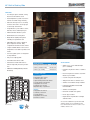
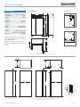
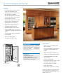
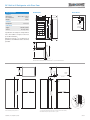
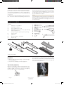
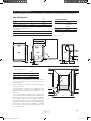
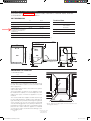
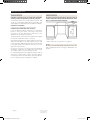
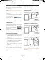
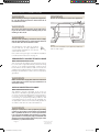
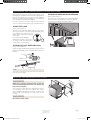
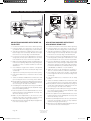
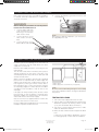
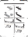
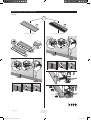
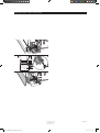
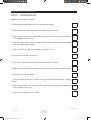
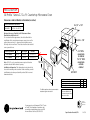
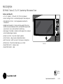
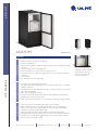
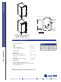
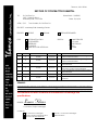
Thomco Job # 3064 RECORD OF CONTRACTOR SUBMITTAL TO: So Cal Gas Co. 1801 S. Atlantic Blvd., Monterey Park, CA 91754 ATTN / C/O: Submittal #: 114530-01 Date: 10/14/14 Tom Souders, So Cal Gas Co. PROJECT: Monterey Park Learning Center PRIORITY: URGENT NORMAL FOR: INFORMATION ONLY AS REQUESTED REFERENCE YOUR FILES SUBMITTALS FOR APPROVAL RESPONSE REQUIRED SENT BY: No. COPIES SPECIFICATION DATED 1 5 114530 10/14/14 2 5 114530 10/14/14 3 5 114530 10/14/14 4 5 114530 10/14/14 5 5 114530 10/14/14 6 1 114530 10/14/14 HAND DELIVER U.S. MAIL ELECTRONIC FAX OTHER DESCRIPTION Sub Zero QRBI-48S Side-By-Side Refrigerator Product Data Submittal Sub Zero QRBI-36RG Beverage Refrigerator Product Data Submittal Asko D5634XKLS ADA Dishwasher Product Data Submittal GE Profile PEB7226SF/EH 2.2 C.U. F.t. Microwave Product Data Submittal U-Line ULI-030 ADA151M Ice Maker Product Data Submittal Appliance Electronic Product Data Submittal REMARKS: _____________________________________________________________________________________ PLEASE REVIEW, STAMP AND RETURN AT LEAST (3) COPIES TO THE GENERAL CONTRACTOR. _____________________________________________________________________________________ This submittal has been reviewed for conformance to drawings and specifications. SIGNED: Louis Kloss Louis Kloss, Project Manager COPIES TO: A/E of Record or Designer Thomco Project Superintendent Thomco File: Submittal File Owner / Construction Manager: Subcontractor: 48" Built-In Side-by-Side subzero.com FEATURES •Four design options: framed, overlay, flush inset and stainless steel. •Dual refrigeration system ensures the freshest food and energy efficiency. •Electronic microprocessor constantly monitors entire unit to ensure proper food storage environment. •Air purification system reduces odors, bacteria, viruses and ethylene gas. •Advanced water filtration system. •Illuminated touch control panel. •Bright interior lighting throughout, including storage drawer area. •Adjustable door shelves, spill-proof glass refrigerator shelves, dairy compartment and wire freezer shelves. •Crisper and deli drawers form a lowertemperature zone ideal for produce and meats. •Soft-close glide system on refrigerator storage drawers. •Easy-access flip-up grille. •Informational freshness cards. •Automatic ice maker with max ice feature temporarily increases production. •ENERGY STAR® qualified (excludes BI-48S/O). ACCESSORIES MODEL OPTIONS Overlay (framed, flush inset) BI-48S/O Stainless (tubular handle) BI-48S/S/TH Stainless (pro handle) BI-48S/S/PH INTERIOR FEATURES REFRIGERATOR •Framed front panels in white or stainless steel. •Flush inset panels in stainless steel with tubular or pro handles. 4 Adjustable glass shelves 1 Stationary glass shelf 1 High-humidity drawer with divider 2 Storage drawers with divider 3 Adjustable door shelves 2 Stationary door shelves Adjustable dairy compartment •Custom front panel mounting kit. FREEZER •Stainless steel kickplate. 3 Adjustable wire shelves 1 Stationary solid shelf 3 Storage drawers 5 Adjustable door shelves Automatic ice maker Model BI-48S •Grilles for 83" or 88" finished height (84" is standard). •Side panel in white or stainless steel. •Stainless steel tubular and pro handles. •Full-length standard and extended framed handles. •Retrofit kit for 600 series panels. •Dozen egg container. •Replacement air purification cartridge and water filter. Accessories available through an authorized Sub-Zero dealer. For local dealer information, visit the find a showroom section of our website, subzero.com. 48" Built-In Side-by-Side subzero.com DIMENSIONS SPECIFICATIONS PRODUCT Dimensions Door Clearance Weight ELECTRICAL 26 3/16" (665) 48" (1219) 48"W x 84"H x 24"D 30 1/2" 630 lb 7" E (178) 6" CAPACITY (152) Refrigerator Freezer 19.1 cu ft 9.8 cu ft 75 1/2" (1918) FROM FLOOR 84" (2134) RIGHT SIDE OF OPENING ELECTRICAL Supply Service 73 3/4" 115 VAC, 60 Hz 15 amp circuit (1873) PLUMBING PLUMBING Supply Pressure 1/ 4" OD copper, braided stainless steel or PEX tubing 35–120 psi RIGHT SIDE OF OPENING HEIGHT DIMENSIONS ± 1/2" (13) 23 7/8" (606) 4" (102) Specifications are subject to change without notice. Visit subzero.com/specs for the most up-to-date information. 18" (457) 23 7/8" 3" (76) (606) Dimensions may vary ± 1/8" (3). Dimensions in parentheses are millimeters unless otherwise specified. 8 3/8" 11 5/8" (213) (295) 6" (152) AREA EXTENDS 1/2" (13) FORWARD ON FLOOR 30" (762) 2 3/8" (60) Dimensions based on stainless steel model. For flush inset, add 1/2" (13) to door clearance dimensions. STANDARD INSTALLATION FLUSH INSET INSTALLATION 26 3/16" 24" (610) OPENING DEPTH (665) FLUSH INSET DEPTH 2 3/16" (56) FINISHED CLEATS* TOP VIEW TOP VIEW 11/4" 1/4" (6) 83 3/4" (2127) OPENING HEIGHT 47 1/2W " (1206) OPENING WIDTH (32) 84" (2134) FLUSH INSET HEIGHT 50" W (1270) FLUSH INSET WIDTH 11/4" (32) 4" (102) 3" (76)* TYPICAL SIDE VIEW NOTE: Shaded line represents profile of unit. FRONT VIEW SIDE VIEW 2 3/16" (56) FRONT VIEW *3" (76) typical depth. Shaded areas will be visible and should be finished to match cabinetry. NOTE: Shaded line represents profile of unit with 3/4" (19) panel. ©Sub-Zero, Inc. all rights reserved. 6/2014 36" Built-In All Refrigerator with Glass Door subzero.com FEATURES •Four design options: framed, overlay, flush inset and stainless steel. •Triple-pane, UV-resistant glass door— high altitude glass available. •Electronic microprocessor constantly monitors entire unit to ensure proper food storage environment. •Air purification system reduces odors, bacteria, viruses and ethylene gas. •Illuminated touch control panel. •Bright interior lighting throughout, including storage drawer area. •Adjustable spill-proof glass shelves. •Crisper and deli drawers form a lowertemperature zone ideal for produce and meats. •Soft-close glide system on refrigerator storage drawers. •Easy-access flip-up grille. •Informational freshness cards ACCESSORIES MODEL OPTIONS Overlay (framed, flush inset) BI-36RG/O Stainless (tubular handle) BI-36RG/S/TH Stainless (pro handle) BI-36RG/S/PH Specify RH or LH door. INTERIOR FEATURES REFRIGERATOR 4 1 1 2 Adjustable glass shelves Stationary glass shelf High-humidity drawer with dividers Storage drawers with dividers •Grilles for 83" or 88" finished height (84" is standard). •Flush inset and dual flush inset panels in stainless steel with tubular or pro handle. •Side panel in white or stainless steel. •Stainless steel tubular and pro handles. •Full-length standard and extended framed handles. •Stainless steel kickplate. •Dual installation kit with or without dual wide grille—84" finished height. Model BI-36RG •Retrofit kit for 600 series panels. •Dozen egg container. •Replacement air purification cartridge. Accessories available through an authorized Sub-Zero dealer. For local dealer information, visit the find a showroom section of our website, subzero.com. 36" Built-In All Refrigerator with Glass Door subzero.com DIMENSIONS SPECIFICATIONS PRODUCT Dimensions Door Clearance Weight ELECTRICAL 26 3/16" (665) 36" (914) 36"W x 84"H x 24"D 37 3/4" 430 lb 7" E (178) 6" CAPACITY (152) Refrigerator 23.4 cu ft 84" ELECTRICAL Supply Service 75 1/2" (1918) FROM FLOOR (2134) 73 3/4" 115 VAC, 60 Hz 15 amp circuit RIGHT SIDE OF OPENING (1873) Specifications are subject to change without notice. Visit subzero.com/specs for the most up-to-date information. Dimensions may vary ± 1/8" (3). Dimensions in parentheses are millimeters unless otherwise specified. HEIGHT DIMENSIONS ± 1/2" (13) 4" (102) 23 7/8" (606) 23 7/8" (606) 14 1/8" (359) 37 1/4" (946) 2 3/8" (60) Dimensions based on stainless steel model. For flush inset, add 1/2" (13) to door clearance dimensions. STANDARD INSTALLATION FLUSH INSET INSTALLATION 26 3/16" 24" (610) OPENING DEPTH (665) FLUSH INSET DEPTH 2 3/16" (56) FINISHED CLEATS* TOP VIEW TOP VIEW 11/4" 1/4" (6) 83 3/4" (2127) OPENING HEIGHT 351/W 2" (902) OPENING WIDTH (32) 84" (2134) FLUSH INSET HEIGHT 38"W (965) FLUSH INSET WIDTH 11/4" (32) 4" (102) 3" (76)* TYPICAL SIDE VIEW NOTE: Shaded line represents profile of unit. FRONT VIEW SIDE VIEW 2 3/16" (56) FRONT VIEW *3" (76) typical depth. Shaded areas will be visible and should be finished to match cabinetry. NOTE: Shaded line represents profile of unit with 3/4" (19) panel. ©Sub-Zero, Inc. all rights reserved. 9/2014 D5634XLHS/TH Tubular handle Features PROGRAMS Heavy wash Delicate wash Quick wash Super quick Eco wash Rinse and dry Rinse and hold OPTIONS Product overview Product:Dishwasher Size:XL Mode of installation:Built-in Energy class:A++ Product:Built-in dishwasher Dimensions of the product (W×H×D):24” × 32 1/4” × 22 7/8” (610 × 819 × 581 mm) Delayed start: 24 h High temperature Long dry CLEANING SYSTEMS Self cleaning filters AquaLevel™ Sensor DRYING SYSTEM Specifications Turbo Drying™ GENERAL COMFORT/EASY OF USE Display type:LED display Number of programs:9 Noise level:48 dB(A) Number of baskets:2 Max loading height upper basket:9 1/16 (230 mm) Max loading height lower basket:12 3/16 (310 mm) Fault indication Rinse-aid indication Time remaining indicator DIMENSIONS AND INSTALLATION Height:32 1/4 (819 mm) Width:24 (610 mm) Depth:22 7/8 (581 mm) Length inlet hose:66 1/8 (1680 mm) Length outlet hose:41 3/4 (1060 mm) Cord length:46 7/16 (1180 mm) Weight net:108 lbs Weight gross:112 lbs SAFETY AquaSafe™ SteamSafe™ KidLock™ - lock the door BASKETS Upper: Premium Lower: Exclusive TECHNICAL INFORMATION Connection rating:1300 W Current:15 A Voltage:120 V CONSUMPTION Wash performance:A Estimated yearly energy consumption:231 kWh Energy consumption/cycle:1,07 kWh ASKO Appliances North America - PO Box 44848 - MADISON WI 53744 Customer Support: CALL US TOLL FREE AT 800-898-1879 DISHWASHER INSTALLATION INSTRUCTIONS T!tions before installing N A T R O IMP f these instruc ll o Read a washer. h is d the AUTOMATIC HIGH LOOP The drain hose is fastened to the back of the machine at the best height. To eliminate potential drain problems, leave this hose in place. CONTENTS INTRODUCTION2 WHAT YOU NEED 2 3 XXL DISHWASHERS UNIT DIMENSIONS PREPARING THE LOCATION 3 3 ADA AND XL DISHWASHERS 4 4 4 UNIT DIMENSIONS PREPARING THE LOCATION CORNER INSTALLATION EASYINSTALL CONNECTIONS WATER SUPPLY DRAIN CONNECTIONS ELECTRICAL CONNECTIONS PREPARING THE DISHWASHER FOR INSTALLATION MOVING THE MACHINE INTO PLACE CONNECTING THE ELECTRIC CABLE CONNECTING THE WATER SUPPLY FASTENING THE DISHWASHER TO THE CABINET INSTALLING THE TOE KICK INSTALLATION CHECKLIST 5 5 6 7 8 9 9 11 11 12 12 16 SAVE THESE INSTRUCTIONS FOR FUTURE REFERENCE 461328 Install DW90 USA EN Rev 01.indd 1 2014-01-16 10:25:52 Introduction Read these instructions carefully and completely before you install the machine. The installation should be carried out by a qualified person who is familiar with all local codes and ordinances for electrical and plumbing connections. has to be done before you move the machine into place. If a dishwasher is being installed in this area for the first time, most of the cabinet work, plumbing, and electrical NOTE: Cosmetic damage must be reported to the ASKO dealer within five days from the date of purchase. As soon as you unpack the dishwasher, thoroughly check it for cosmetic damage. If you are replacing an old dishwasher, you must check the plumbing connection and wiring before you move the new dishwasher into place. what you need TOOLS 1) Phillips No. 2 screwdriver 2) Flat blade screwdriver 3) Torx screwdriver size T 20 4) Adjustable wrenches (if you use copper fittings) 5) Open-ended wrench (1/2˝ [12 mm], 5/8˝ [16 mm] and 1˝ [24 mm]) 6) Tape measure 7) Spirit level 8) Electric drill with 1-1/2˝ drill bit 9) Keyhole saw MATERIALS SUPPLIED 4 * * 5 * * 6 8 3 2 2x 2x 1" (25 mm) * 1 * 7 9 4x / 3x * Only select models. MATERIALS • Minimum 3/8˝ OD copper tubing of sufficient length for your installation • Shut-off valve and fittings for water supply line The dishwasher is shipped with the high loop drain hose, inlet hose and electrical cord attached and ready to be connected. Please do not remove the high loop connection for the drain line. Tip Guards (optional) When it is not possible to attach the dishwasher to the cabinet or the underside of the counter top, you should install tip guards to prevent the machine from tipping when you open the door. Sold individually. Tip Guards (P/N 8070851) Page 2 461328 Install DW90 USA EN Rev 01.indd 2 Customer Care Center 1-800-898-1879 www.askona.com 2014-01-16 10:25:53 XXL DISHWASHERS D5434XXL W/B/S, D5624XXLS, D5634XXLHS, D5654XXLHS, D5894XXLHS, D5894AXXLHS UNIT DIMENSIONS U.S. Metric Technical Data Height (Adjustable)* 34-3/8˝ to 36-1/2˝ 873 mm to 927 mm Electricity 120V, 60Hz, 15 amp Width 24˝ 610 mm Water pressure Depth (Includes high loop) 22-7/8˝ 581 mm DepthW/handle 24-7/8˝ (D5634XXLHS, D5654XXLHS, D5894XXLHS) 632 mm 4.2 - 140 psi, 0.03-1.0 MPa, 0.3-10 Bar Heating element 1200 watt Depth W/Door Open 49-1/2˝ 1257 mm Max loading 1300 watt Weight 110 Ib 50 kg * Total height can be reduced by 1/2˝ (13 mm) by removing upper trim, and lowering side trim (2). 49-1/2" 1257 mm 24-7/8"; 632 mm D5634XXLHS, D5654XXLHS, D5894XXLHS 22-7/8" 581 mm 5-3/8" to 7-3/8" 137 mm to 187 mm *34-3/8" to 36-1/2" *873 mm to 927 mm 24" 610 mm 2-7/8" 73 mm Door 3-3/8" 86 mm 2" 50 mm 9" 229 mm PREPARING THE LOCATION Width 24˝ 610 mm Depth 24˝ 610 mm The best place for your dishwasher is in the kitchen near the sink. This makes it easier to connect the water and drain supply lines. A built-in dishwasher must be enclosed on the top, both sides and the back. The electrical and water supplies should enter through the area indicated by the shading on the illustration at right. Preferably, they should come through the right side of the machine. The access hole must be round and smooth and no bigger than 1-1/2˝ (38 mm) in diameter. If the partition is metal, it needs to be covered with an edge protector. Use caution when the appliance is installed or removed, to reduce the likelihood of damage to the power-supply cord. Customer Care Center 1-800-898-1879 www.askona.com 461328 Install DW90 USA EN Rev 01.indd 3 5-3/8" 136 mm 61 24" 0 m m The power-supply receptacle for the appliance shall be installed in a cabinet or on a wall adjacent to the undercounter space in whitch the appliance is to be installed. 873-927 mm Metric 873 to 927 mm 34-3/8" to 36-1/2" minimum U.S. 34-3/8˝ to 36-1/2˝ Height 10 4" 51 2" 2 m m m m Cutout Dimensions 24" 610 mm Page 3 2014-01-16 10:25:54 ADA AND XL DISHWASHERS D5424ADA W/B/S, D5634ADAHS, D5424XL W/B/S, D5624XLCS, D5434XL W/B/S, D5454XL S, D5634XLHS, D5638XLHS, D5644XLCS UNIT DIMENSIONS U.S. Metric Technical Data Height (Adjustable)* 32-1/4˝ to 34˝ 819 mm to 864 mm Electricity 120V, 60Hz, 15 amp Width 24˝ 610 mm Water pressure Depth (Includes high loop) 22-7/8˝ 581 mm DepthW/handle (D5634ADAHS, D5624XLCS, D5634XLHS, D5638XLHS, D5644XLCS) 24-7/8˝ 632 mm 4.2 - 140 psi, 0.03-1.0 MPa, 0.3-10 Bar Heating element 1200 watt Max loading 1300 watt Depth W/Door Open 48-3/8˝ 1229 mm Weight 108 Ib 49 kg * 32-1/4˝ (819 mm) height requires removal of top trim, and lowering side trim (2). 48-3/8" 1229 mm 24-7/8"; 632 mm DepthW/handle 24" 610 mm 5-3/8" to 8-1/8" 137 mm to 206 mm 32-1/4"* to 34" 819* mm to 864 mm 22-7/8"; 581 mm 2-7/8" 73 mm Door 3-3/8" 86 mm 2" 50 mm 9" 229 mm PREPARING THE LOCATION Height *32-1/4˝ to 34˝ 819 to 864 mm Width 24˝ 610 mm Depth 24˝ 610 mm The best place for your dishwasher is in the kitchen near the sink. This makes it easier to connect the water and drain supply lines. A built-in dishwasher must be enclosed on the top, both sides and the back. 5-3/8" 136 mm The electrical and water supplies should enter through the area indicated by the shading on the illustration at right. Preferably, they should come through the right side of the machine. The access hole must be round and smooth and no bigger than 1-1/2˝ (38 mm) in diameter. If the partition is metal, it needs to be covered with an edge protector. Use caution when the appliance is installed or removed, to reduce the likelihood of damage to the power-supply cord. Page 4 461328 Install DW90 USA EN Rev 01.indd 4 61 24" 0 m m The power-supply receptacle for the appliance shall be installed in a cabinet or on a wall adjacent to the undercounter space in whitch the appliance is to be installed. *819-864 mm Metric *32-1/4" to 34" minimum U.S. 10 4" 51 2" 2 m m m m Cutout Dimensions 24" 610 mm * 32-1/4˝ (819 mm) height requires removal of top trim, and lowering side trim (2). Customer Care Center 1-800-898-1879 www.askona.com 2014-01-16 10:25:55 CORNER INSTALLATION If the dishwasher is installed in a corner, there must be a minimum clearance of 2˝ (50 mm) from the side wall so the door can open. 2˝ clearance EASYINSTALL CONNECTIONS PEX tubing with 3/8˝ compression fitting PEX tubing has a 95-year spec life. Fits American dishwasher water supply valves. Be sure to install the O-Ring which is attached to the PEX tubing in a plastic bag. Drain hose boot Ready to be cut to desired drain connection. Only one clamp required. Electrical cord 120 volts, 15 amp cord is supplied with the dishwasher. WARNING! Do not use an extension cord for this appliance. Customer Care Center 1-800-898-1879 www.askona.com 461328 Install DW90 USA EN Rev 01.indd 5 Page 5 2014-01-16 10:25:56 WATER SUPPLY WARNING! Plumbing connections must comply with applicable sanitary, safety and plumbing codes in your area. The machine can be connected to either a hot (max. 160 °F, 70 °C) or cold water supply. We recommend a cold water supply. The water pressure should be 4.2-140 psi. WARNING! In order to prevent heat damage to the inlet valve, all solder connections must be made before the water line is connected to the dishwasher. Connect to cold water... If you use oil or electricity to heat your home. Connect to hot water (max 160 °F, 70 °C)... If you use district heating, solar power, or geothermal power to heat your home. Choosing a hot water connection cuts program times and reduces the dishwasher’s electricity consumption. The dishwasher comes with a 6-foot PEX water supply line that has a 3/8˝ NPT female connection. After determining where the water supply line will enter under the sink, drill a 1-1/2˝ (38 mm) access hole and run the line to the approximate inlet valve location shown in the figure below. The water line inlet valve is on the right rear of the machine. For service convenience, a shut-off valve (not supplied) should be installed in the supply line in an easily accessible location, such as, beneath the sink. 1. Water supply 2. Water supply valve to dishwasher (not supplied) NOTE: Be sure to run the PEX tubing through the hole to the sink compartment before moving the dishwasher into position. It is important that the water supply line and the shut off valve have a sufficient flow volume. At least 3 gallons (12 liters) per minute must be able to pass through the line. The water pressure should be 4.2-140 psi. Page 6 461328 Install DW90 USA EN Rev 01.indd 6 Customer Care Center 1-800-898-1879 www.askona.com 2014-01-16 10:25:56 DRAIN CONNECTIONS ASKO provides a 7/8˝ (22 mm) diameter corrugated drain hose which is connected to the back of the unit to form a high loop. NOTE: Do not use any fittings anywhere in the drain line that are less than 7/8˝ (22 mm) OD. THREE WAYS TO INSTALL DRAIN CONNECTIONS A) Typical connection to sink plumbing before trap (high loop drain) The access hole for the drain line should be 1-5/8˝ (41 mm)2˝ (50mm) max. The end of the drain line is 1/2˝ (12 mm), but it is adjustable to 7/8˝, 3/4˝, 5/8˝ (22 mm, 19 mm, and 16 mm). If the drain connection is larger than 1/2˝ (12 mm), you can easily cut the drain line to fit the connection. 508 The illustrations to the right show three ways to connect the drain supply line. THE HIGH LOOP The high loop is necessary for proper draining. Therefore, all ASKO dishwashers have the drain hoses attached to the drain pump and fastened to the top back of the unit, as illustrated. This gives the drain hose an automatic high loop, which is necessary for proper draining. The drain hose is fastened at the best high loop height. B) Connection to air gap then to the trap To eliminate potential drain problems, simply leave this hose in place. 508 DO NOT REMOVE THE HIGH LOOP ATTACHED TO THE BACK OF THE DISHWASHER! IMPORTANT THINGS TO REMEMBER: ♦ Failure to provide the proper drain connection height (minimum of 20˝ (508 mm) above the bottom of the dishwasher base) or a 20˝ (508 mm) high loop will result in improper drainage, which will damage the machine. ♦ No part of the drain hose should be higher than 35˝ (889 mm) from the bottom of the dishwasher. ♦ The drain hose can be extended to a maximum length of 10 feet (3048 mm). Joints and jointed tubes, if any, must have a minimum 7/8˝ (22 mm) OD. ♦ If the drain line is going to be connected to a waste disposer, be sure to remove the knockout or plug from the fitting on the disposer before connecting the drain line. ♦ Do not use fittings smaller than 7/8˝ (22 mm) OD; otherwise the water may not drain properly. When the installation is ready, open the supply valve to pressurize the fill system. Then check that all connections are tight and there are no leaks. C) Connection to waste disposer with air gap 508 NOTE: Don’t forget to remove the knockout or plug from the disposer fitting. Customer Care Center 1-800-898-1879 www.askona.com 461328 Install DW90 USA EN Rev 01.indd 7 Page 7 2014-01-16 10:25:56 ELECTRICAL connections WARNING! Before working on wiring for any electrical appliance, be sure the electrical power has been turned off at the breaker/fuse box. WARNING! Do not use an extension cord for this appliance. WARNING! Disconnect the electrical power supply and place a tag at the disconnect switch indicating that you are working on the circuit. WARNING! 7 185 Electrical and grounding connections must comply with the applicable portions of the national electrical code and/or other local electrical codes. NOTE: Access holes should be 1-1/2˝ (38 mm) in diameter with no sharp edges. The dishwasher comes with an electrical cord for 120 volts, 15 amp supplied. This cord should be plugged into the 120 volt outlet under the sink. If the cord is not long enough, or if a hard-wire installation is needed, follow instructions on page 11. PERMANENTLY-CONNECTED APPLIANCE Grounding instructions This unit must be grounded to operate properly. It must be connected to a grounded metal, permanent wiring system, or an equipment-grounding conductor must be run with the circuit conductors and connected to the equipment-grounding terminal or lead of the appliance. Damage to the dishwasher could occur if it is not properly grounded. WARNING! Make sure the water supply line, drain line and branch circuit wiring do not touch any exposed terminals of dishwasher wiring. CORD-CONNECTED APPLIANCE Grounding instructions This appliance must be grounded. In the event of a malfunction or breakdown, grounding will reduce the risk of electric shock by providing a path of least resistance for electric current. This appliance is equipped with a cord having an equipment-grouding conductor and a grounding plug. The plug must be plugged into an appropriate outlet that is installed and grouded in accordance with all local codes and ordinances. WARNING! Improper connection of the equipment-grounding conductor can result in a risk of electric shock. Check with a qualified electrican or service representative if you are in doubt whether the appliance is properly grounded. Do not modify the plug provided with the appliance, if it will not fit the outlet, have proper outlet installed by a qualified electrician. Page 8 461328 Install DW90 USA EN Rev 01.indd 8 Customer Care Center 1-800-898-1879 www.askona.com 2014-01-16 10:25:57 PREPARING THE DISHWASHER FOR INSTALLATION At this point the styrofoam, plastic wrap, and the wood pallet (base) should be removed from the dishwasher. Now is an excellent time to inspect for any shipping damage. Should you find any damage, you should report it to your dealer or builder immediately. Be sure to remove the toe kick and toe kick insulation (only on certain models) from the top of the dishwasher. Attach the supplied door sealing (Only certain models.) This strip is an essential part of the Turbo Dry Express system and must be installed to ensure an optimum seal between the dishwasher tank and door. 1 SLIDES FOR LEGS (Only certain models.) The unit comes with white plastic slides for the legs to protect the kitchen floor from being damaged when you slide the unit into place. The slides simply snap onto the bottom of the legs. Use caution when sliding the dishwasher into place. The protective slides could cause damage to certain types of soft flooring. 3 2 1 Attach the light shielding film (Only certain models.) Attach the light shielding film (packed in the document bag) to the underside of the countertop above the touch buttons. 2 NOTE: The surface on which the protective film is to be attached must be clean and dry. Moving the machine into place WARNING! Make sure you put the protective slides on the legs to prevent damaging the floor when you slide the unit into place (see page 9). As you do this, feed the drain line and inlet hose into the access hole(s) in the side of the cabinet. Use caution when sliding the dishwasher into place. The protective slides could cause damage to certain types of soft flooring. WARNING! Be careful of sharp edges. Customer Care Center 1-800-898-1879 www.askona.com 461328 Install DW90 USA EN Rev 01.indd 9 Page 9 2014-01-16 10:25:59 Moving the machine into place Rear foot Front feet 1˝ (24 mm) 1˝ (24 mm) Adjusting machines with three or four feet Adjusting machines with FRONT ADJUSTABLE REAR Foot 1. Position the machine in front of the cabinet opening. 1. Position the machine in front of the cabinet opening. 2. Push the plastic feet into place on all steel feet (included in document bag). (Only certain models.) 2. Push the plastic feet into place on all steel feet (included in document bag). (Only certain models.) 3. Start by measuring the height from the floor to the bottom edge of the counter top. Measure the height from the floor to the top edge of the dishwasher. 3. Start by measuring the height from the floor to the bottom edge of the counter top. Measure the height from the floor to the top edge of the dishwasher. 4. Loosen the lock nuts on the dishwasher’s steel feet using a 5/8˝ (16 mm) open-ended wrench. Screw the lock nuts down as close to the floor as possible. 4. Loosen the lock nuts on the dishwasher’s front steel feet using a 5/8˝ (16 mm) open-ended wrench. Screw the lock nuts down as close to the floor as possible. 5. Make the height adjustment while the dishwasher is in front of the opening. Adjust all feet by turning them clockwise to raise or counterclockwise to lower the dishwasher. 5. Lean the dishwasher forwards a little and roughly adjust the rear foot by turning the adjustment screw at the front clockwise to raise and counterclockwise to lower the dishwasher (see illustration above). Use a flat-bladed screwdriver or a 1/4˝ nut driver. 6. Check that the height of the machine corresponds to the height from the floor to the bottom edge of the counter top. 7. Tighten the lock nuts (lock nut) on the rear feet (foot). 8. Pull out the drain hose to ensure there are no sharp bends. 9. Start to feed water and drain lines and electric cord (if necessary) into the access hole(s) in the cabinet. 10.Gently slide the unit into the dishwasher opening. As you do this, feed the drain line and inlet hose into the access hole(s) in the side of the cabinet. 11.If installing in a metal cabinet, the hole(s) for the drain hose and connection pipe must be fitted with edge protectors/rubber grommets. 12.Place the spirit level on the dishwasher door to check that the machine is level and adjust if necessary. The door must be fully closed! 13.Make any final adjustments to the front feet. (The machine may have an inclination of 3/16˝ (5 mm) maximum without affecting its performance.) 14.When the front feet are properly adjusted, tighten the lock nuts to the base pan. Page 10 461328 Install DW90 USA EN Rev 01.indd 10 6. Adjust the front feet by turning them clockwise to raise or counterclockwise to lower the dishwasher. 7. Check that the height of the machine corresponds to the height from the floor to the bottom edge of the counter top. 8. Pull out the drain hose to ensure there are no sharp bends. 9. Start to feed water and drain lines and electric cord (if necessary) into the access hole(s) in the cabinet. 10.Gently slide the unit into the dishwasher opening. As you do this, feed the drain line and inlet hose into the access hole(s) in the side of the cabinet. 11.If installing in a metal cabinet, the hole(s) for the drain hose and connection pipe must be fitted with edge protectors/rubber grommets. 12.Place the spirit level on the dishwasher door to check that the machine is level and adjust if necessary. The door must be fully closed! 13.Make any final adjustments to the feet. (The machine may have an inclination of 3/16˝ (5 mm) maximum without affecting its performance.) 14.When the feet are properly adjusted, tighten the lock nuts on the front feet to the base pan. Customer Care Center 1-800-898-1879 www.askona.com 2014-01-16 10:26:01 CONNECTING THE ELECTRIC CABLE If the cord is not long enough, or if a hard-wire installation is needed, follow the steps below to complete the electrical connection. 4. Connect ground wire to ground connection screw on the bottom. WARNING! Before starting this procedure, be sure the power is turned off at the breaker/fuse box. 1. Connect supply cable with a UL-listed strain relief bushing (if nonmetallic cable is to be used). 2. Connect branch circuit white lead to N lead on filter. NOTE: When doing a hard-wire installation, you must remove the supplied power cord. 3. Connect branch circuit black lead to L lead on filter. CONNECTING THE WATER SUPPLY In order to prevent heat damage to the inlet valve, all solder connections must be made before the water supply line is connected. Flush the water supply line prior to connecting it to the water fill tube. The unit has a float switch in the base pan to protect against flooding. If the inlet valve connection is not seated properly, water may leak into the base pan and activate the float switch. Water connection should be carried out by a qualified professional. It is important that the water supply line and the shut-off valve have a sufficient flow volume. At least 3 gallons (12 liters) per minute must be able to pass through the line. Connect the machine using the accompanying supply hose. Water pressure should be 4.2-140 PSI. There should be a shut off valve on the water pipe. If the pipes are newly installed, it may be wise to flush them through so that any debris is washed away. Otherwise, debris can clog the filter in the machine’s water intake and cut off the water supply. Only use the inlet hose supplied with the machine. Do not reuse old or other loose inlet hoses. Use the supplied O ring and tighten the connection by hand plus a quarter turn with a wrench. 1. Water supply 2. Water supply valve to dishwasher (not supplied) NOTE: Be sure to run the PEX tubing through the hole leading to the sink compartment before moving the dishwasher into position. TESTING for leaks 1. Turn on the water supply and check for leaks. 2. Turn the power on at breaker/fuse box and test the dishwasher operation by running a Rinse & Hold cycle. (This should take about six minutes.) 3. Turn off the electrical power and check for leaks under the dishwasher and sink. 4. Make sure that no kinks have developed in the drain lines. If there are no leaks and the dishwasher seems to be working properly, continue with the installation. Customer Care Center 1-800-898-1879 www.askona.com 461328 Install DW90 USA EN Rev 01.indd 11 Page 11 2014-01-16 10:26:01 FastenING the dishwasher to the cabinet It’s necessary to fasten the dishwasher to the cabinet so it won’t tilt when the door is opened or if something heavy is placed on the door. Use only the stainless steel screws provided with the machine. 1 1. Use option A for U.S. or European standard installations. Use option 3 B only for European standard installations, or U.S. installations 2 where there is a hard counter-top such as tile or marble. 4x / 3x 2. When the machine is properly attached, check that the feet are tight against the floor and that the machine is level. 4 2x 5 2x NOTE: When it is not possible to attach the dishwasher to the cabinet or the underside of the counter top, you should install tip guards to prevent the machine from tipping when you open the door. Sold individually. 1" (25 mm) NOTE: Be sure to use white spacers to keep from over-tightening the mounting screws. Tip Guards (P/N 8070851) INSTALLING THE TOE KICK ? 6 7 Type A See page 13 Page 12 461328 Install DW90 USA EN Rev 01.indd 12 Type B See page 14 Customer Care Center 1-800-898-1879 www.askona.com 2014-01-16 10:26:02 INSTALLING THE TOE KICK type A ? 8 9 Insulation material Insulation material 1. 1. 2. The toe kick is attached with two screws that can only be adjusted vertically. 2. 3. The toe kick is attached with two screws that can only be adjusted vertically. NOTE: or NOTE: or Customer Care Center 1-800-898-1879 www.askona.com 461328 Install DW90 USA EN Rev 01.indd 13 Page 13 2014-01-16 10:26:05 INSTALLING THE TOE KICK type B ? 8 9 Insulation material Insulation material 1. 1. 2. 2. 3. Page 14 461328 Install DW90 USA EN Rev 01.indd 14 Customer Care Center 1-800-898-1879 www.askona.com 2014-01-16 10:26:07 INSTALLING THE TOE KICK 4. 5. x x 6. Customer Care Center 1-800-898-1879 www.askona.com 461328 Install DW90 USA EN Rev 01.indd 15 Page 15 2014-01-16 10:26:09 INSTALLATION CHECKLIST Asko - Dishwasher Appliance Installation Checklist • Remove packaging and check for cosmetic damages. • Remove the information packets from inside the dishwasher. • Attach any accessories as required by the installation. Fill strips, light shielding film, supplied door sealing... • Attach the drain line using the largest section of the disposer boot allowable. Leave the high loop in place. • Attach the PEX fill hose. Don’t forget to use the O-ring. • Plug the dishwasher into the wall. • Turn on the water and check the fill line connections for leaks. • Slide the unit into the cabinet and level the machine front to rear, and left to right. • Mount the unit to the cabinet. • Turn the power to the unit on and start a cycle. Make sure there are no drain leaks. • Show the customer their warranty card, and help them locate the model and serial number on the unit. • Leave all user books for consumer. Page 16 461328 Install DW90 USA EN Rev 01.indd 16 Art. No 461328 Rev. 01 Customer Care Center 1-800-898-1879 www.askona.com 2014-01-16 10:26:09 PEB7226SF/EH GE Profile™ Series 2.2 Cu. Ft. Countertop Microwave Oven Dimensions and Installation Information (in inches) Exterior Dimensions (in inches) W x H x D 25-1/2" ± 1/8" 24-1/8 x 14 x 19-3/4 Optional Accessory Trim Kits for GE Microwave Ovens (Available at additional cost) For a custom built-in appearance, these kits allow built-in installation of the countertop microwave oven into a wall or cabinet alone and are U.L. approved for installation over a GE single electric wall oven. These kits should not be installed over a gas wall oven. Accessory trim kits "Z" Max Height Trim Kits 30" Deluxe 29-3/4" 19-1/8" JX7230SFSS 27" Deluxe 26-3/4" 19-1/8" JX7227SFSS Note: 120V, 60-cycle, grounded power receptacle location optional on back within cabinet opening. A 16-3/4" ± 1/8" C B 19-1/8" Trim Kit Installation Information: This information is not intended to be used for installing unit described. Before installing, consult installation instructions packed with product/kit for current dimensional data. 22" MIN. receptacle in cabinet 19-1/2" MIN. receptacle outside cabinet Bra cke t 36" MIN.* Z Cabinet overlap requirements 30" 27" A - Overlap of trim kit over top of cabinet 1" 1" B - Overlap of trim kit over bottom of cabinet 1-3/8" 1-3/8" C - Overlap of trim kit over sides of cabinet 2-1/8" 5/8" *For ADA compliance, the microwave must be installed no higher than 36-1/4". Accessory Trim Kits ™ JX7230 For answers to your Monogram,® Cafe Series ™ or Profile Series appliance questions, visit JX7227 our website at geappliances.com or call GE Answer Center® service, 800.626.2000. Note: Allow an additional inch of clearance beyond trim frame on all sides Listed by Underwriters Laboratories Z 29-3/4" 26-3/4" Specification Revised 5/14 240379 PEB7226SF/EH GE Profile™ Series 2.2 Cu. Ft. Countertop Microwave Oven Features and Benefits • 2.2 cu. ft. capacity - 1100 watts (IEC-705 test procedure) • Sensor cooking controls - Automatically adjusts time and power • Optional built-in trim kit - Custom appearance and built-in convenience • Weight and time defrost - Simply enter the weight of the food, and the oven automatically sets the optimal defrosting time and power level or set your desired time for defrosting • Extra-large 16" turntable - Rotates food throughout the cycle and accommodates large cookware • Instant on controls - One-touch instant operation • Control lockout - Helps prevent accidental activation • Add 30 seconds - Add 30 seconds of microwave cooking time • Kitchen timer - Minute timer helps keep you on track • Model PEB7226SFSS – Stainless steel • Model PEB7226EHES - Slate PEB7226SF Listed by Underwriters Laboratories Specification Revised 5/14 240379 1A0D7A5 1W 5 1CMS ADA151M Stainless Black ADA S e ri e s PERFORMANCE • Daily ice rate of up to 25 lbs of crescent ice • Stores up to 25 lbs of ice • Uses less than 3 gallons of water to produce 25 lbs of ice, conserving both energy and water • Uses less energy than a 75 watt light bulb • Perfect size crescent ice cubes (1/2"W x 3/4"H x 2-1/2"L) • Mechanical control monitors ice making operation to ensure maximum daily ice production • Manual defrost • UL residential and commercial listings Interior / Exterior • 32" height meets ADA height requirement • No drain required, easy and inexpensive to install and requires only a 1/4" outside diameter water line • Stainless steel wrap door with black end caps on stainless model must be ordered left or right hand hinged • Black door model is field reversible • Standard commercial stainless steel handle is interchangeable with professional handle option on stainless steel model • Black vinyl clad textured cabinet is more resistant to scratching, peeling and flaking INTEGRATION ICE MAKERS FEATURES • Unit can be built-in or freestanding providing a custom aesthetic • Black model will accept a 1/4" insert panel to match with surrounding decor • Allow a 2-1/2" clearance on hinged side for 90° door opening when installed adjacent to a wall (for stainless steel model) • Allow 1/4" width overall for proper installation (see back side for details) • No additional clearance around sides, top or rear of unit is needed for ventilation • Durable, factory installed leveling legs provide a more precise undercounter fit • Do not obstruct front grille air flow No ice shortages here. Produces up to 25 pounds of crescent ice (1/2" W x 3/4" H 2-1/2" L) per day. No drain required. 8900 North 55th Street Milwaukee, Wisconsin 53223 414.354.0300 Fax 414.354.7905 u-line.com 7 51 B V A1D0 A 5 1E M 23"* 32" 15" *Add 3/4” To Depth For Water Line Clearance 23"* 23-3/4" Minimum 32" to 33" 4" 1-3/4"* W E 32" 3-9/16"* 1-7/8"* 15-1/4" *Can Vary Up To +1” Depending On Height Of Leveler Legs Legend: E - Electrical W - Water 15" *Add 3/4” To Stainless Depth For Water Line Clearance ADA151MS Model and ADA151MB Black Model * Add 3/4" for water line clearance DIMENSIONS AND SPECIFICATIONS ICE MAKERS Overall Dimensions ADA15IM Height Width Depth – black model With stainless steel handle 32" (81.2) 15" (38.1) 23" (69) 24-7/8" (63) Shipping weight 86 lbs (39 kg) Running amps Maximum start-up amps Amps pertain to voltage rating 2.5 18.0 110/115 volt, 60 Hz Capacities: Approximate daily ice production Ice storage Manual defrost Up to 25 lbs Up to 25 lbs Stainless Right-hand U-ADA15IMS-00 Stainless Left-hand U-ADA15IMS-01 Black U-ADA15IMB-00 Optional in 220/230 voltage, 50/60 Hz On the 220/230 volt models, amps are decreased by approximately 50 percent. Please visit www.u-line.com for installation guide. All specifications are subject to change without notice. 8900 North 55th Street Milwaukee, Wisconsin 53223 414.354.7905 414.354.0300 Fax 414.354.7905 u-line.com