1
Analog and Digital I/O RF Telemetry System
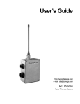
RTU-150/450 Radio Telemetry Units
TECHNICAL SPECIFICATIONS
Document Features
1.
2.
3.
4.
5.
6.
7.
8.
9.
10.
11.
12.
13.
14.
15.
16.
17.
FCC Regulations
RITRON Warranty
Cautions
Introduction
Operation
General Specifications
Interconnects
Software Configuration
Mounting Information
Power
Serial Link
I/O Mapping
Digital Inputs
Digital Outputs
Analog Inputs
Analog Outputs
Theory of Operation
1
OWNER INFORM ATION
1. FCC REGULATIONS
1.1. LICENSING
The FCC requires you to obtain a station license for your DATAFLOW RTU system before using it, but does
not require an operation license or permit. The station licensee is responsible for ensuring that the
transmitter power, frequency and deviation are within the limits specified by the station license. The
licensee is also responsible for the proper operation and maintenance of the radio equipment. This includes
checking the transmitter frequency and deviation periodically, using appropriate methods.
Your RITRON dealer can help you obtain a FCC license. To get a FCC license for VHF or UHF frequencies,
submit FCC application Form 600.
1.2. SAFETY ST ANDARDS
The FCC (with its action in General Docket 79-144, March 13, 1985) has adopted a safety standard for
human exposure to radio frequency electromagnetic energy emitted by FCC regulated equipment. RITRON
observes these guidelines, and recommends that you do also:
1.
2.
3.
4.
DO NOT hold the DATAFLOW RTU such that the antenna is very close to or touching
exposed parts of the body, especially the face or eyes, while transmitting.
DO NOT operate radio equipment near electrical blasting caps or in an explosive
atmosphere.
DO NOT allow children to play with any radio equipment that contains a transmitting device.
Repair of RITRON products should be performed only by RITRON authorized personnel.
2. RIT RON, INC. LIMIT ED WARRANT Y
2.1. WHAT THIS WARRANT Y COVERS
RITRON, INC. ("RITRON") provides the following warranty against defects in material and/or workmanship
in RITRON DATAFLOW RTU’s, Rechargeable Batteries and Accessories under normal use and service
during the applicable warranty period (as stated below). "Accessories" means antennas, chargers, modules,
cables and connectors. Rechargeable batteries will be replaced during the applicable warranty period only if
leakage occurs or the batteries drop below 75% of rated capacity.
WHAT IS COVERED FOR
HOW LONG
WHAT RITRON WILL DO
RITRON DATAFLOW RTU
1 year parts/labor *
During the first year after purchase
RITRON will refund your purchase
price or repair or replace the defective
product, at RITRON’s option, parts
and labor included at no charge to
you.
RITRON DATAFLOW RTU
Rechargeable Batteries
1 year *
RITRON will replace the defective
batteries.
RITRON DATAFLOW RTU
Accessories
90 days*
RITRON will repair or replace the
defective accessory, at RITRON’s
option, parts and labor included at
no charge to you.
* After date of purchase
2.2. WHERE THE WARRANT Y IS VALID
This warranty is valid only within the United States, the District of Columbia, and Puerto Rico.
2
3. CAUT IONS
1.
2.
3.
4.
5.
6.
7.
8.
9.
ALL DIGITAL INPUTS, ANALOG INPUTS, ANALOG OUTPUTS, AND MEASUREMENTS OF THE DATAFLOW RTU ARE
REFERENCED TO GROUND. DO NOT USE THE DATAFLOW RTU WITH EQUIPMENT THAT REQUIRES COMPLETE
ISOLATION.
ALL DATAFLOW RTU DIGITAL OUTPUTS ARE ISOLATED LATCHING RELAYS. DO NOT EXCEED CONTACT RATINGS
OF THESE RELAYS.
EXCITATION VOLTAGE AND LOAD DRIVE VARY FROM MANUFACTURER TO MANUFACTURER. CONSULT THE
MANUFACTURER DOCUMENTATION BEFORE CONNECTING THE SENSORS OR INDICATORS TO THE DATAFLOW
RTU.
DATAFLOW RTU CASE IS CONNECTED TO GROUND.
DATAFLOW RTU SYSTEMS REQUIRE AN FCC LICENSE. PRIOR TO OPERATION CONTACT RITRON FOR LICENSING
INFORMATION.
THE FREQUENCY DEVIATION IS CONTROLLED BY VARIABLE RESISTOR R131. THIS DEVIATION ADJUSTMENT
SHOULD ONLY BE PERFORMED BY AUTHORIZED RITRON PERSONNEL USING THE APPROPRIATE METHODS AND
TEST EQUIPMENT.
DO NOT SHORT THE RED WIRE (PIN 6) OF CONNECTOR J105 TO GROUND.
DO NOT SHORT THE RED WIRE (PIN 5) OF CONNECTOR J101 TO GROUND.
IF AN INTERNAL BATTERY IS INSTALLED DO NOT SHORT THE ORANGE WIRE (PIN 7) OF CONNECTOR J105 TO
GROUND. PERFORMING ANY OF THESE ACTIONS WILL DESTROY THE FUSE (F101) LOCATED ON THE DATAFLOW
RTU CONTROL BOARD.
DO NOT OPERATE THE DATAFLOW RTU WITHOUT AN ANTENNA OR SUITABLE LOAD.
TO DO SO MAY DAMAGE THE TRANSMITTER.
4. INT RODUCTION
4.1 The DATAFLOW RTU from RITRON is a complete wireless telemetry system designed to deliver
industrial instrumentation signals from a source to other instruments via radio frequency communications.
The DATAFLOW RTU allows you to access industrial measuring devices in remote locations without
running wires, installing microwave links or leasing a telephone line. RITRON DATAFLOW RTU and
MODBUS radio communications equipment replaces these methods.
4.2 This manual is intended to provide information needed for the installation and operation of RITRON
DATAFLOW RTU systems. The intended readers are people familiar with industrial instrumentation. A basic
understanding of radio communications is helpful.
5. OPERATION
5.1 DATAFLOW RTU is a radio telemetry system that operates on either UHF-FM (450-470 MHz with a
transmitter power of 2 Watts or 5 Watts) or VHF-FM (150 to 165 MHz, 136 to 151 MHz and 160 to 174 MHz
with a transmitter power of 5 Watts). An RTU system operating in the UHF-FM band at 2 Watts with
directional antennas and 50-foot towers has an effective range of 20 to 25 miles over level terrain. Changes
in the frequency of operation, transmitter power, terrain and antenna structure will affect the range of the
link.
3
6 GENERAL SPECIFICATIONS
6.1 SYSTEM SPECIFICAT IONS:
FCC ID:
RTU-150 - AIERIT04-150
RTU-450 - AIERIT04-450
10K8FID
Maximum of 6
programmable from 0 to 5 V
programmable from 0 to 5 V
2 isolated latching relays
2.0A 30VDC
.5A 110VDC
.5A 125VAC
Maximum of 6
0-5 VDC
0-20 mA
8 bits
Maximum of 2
0-5 VDC
0-20 mA
8 bits
FSK, 1200 BPS, proprietary ManchesterEncoded data format
RS-485; 1200, 2400, 4800, or 9600 BPS;
ASCII; for programming – external control
utilizes RTU Modbus protocol
10-16 VDC 300uA sleep, 100 mA receive
1.5A low power transmit
2.5A high power transmit
Diecast Aluminum, Weather resistant
4.5" x 3.5" x 2.2"
1.4 lb.
-30 to +60 degrees Centigrade
Emission designator:
Digital Inputs:
LOW:
HIGH:
Digital Outputs:
UL/CSA rating:
Analog Inputs:
Voltage Mode Range:
Current Loop Mode Range:
Resolution:
Analog Outputs:
Analog Voltage Mode Range:
Current Loop Mode Range:
Resolution:
Radio Communications:
Serial Communications:
Power Requirements:
Housing:
Dimensions (L x W x H):
Weight:
Operating Temperature:
6.2 DT X SPECIFICAT IONS:
T RANSMITTER
Bandspread:
Freq. Stability:
RF Power Out:
RF Output Z:
Mod. Dist.:
20 MHz
5 PPM
5 W, programmable to 2 W
50 Ohms
< 4%
RECEIVER
Bandspread:
Freq. Stability
Sensitivity:.
RF Input Z:
Selectivity:
Mod. Input Z:
100 K Ohms
Audio Dist.:
20 MHz
5 PPM
3 mV
50 Ohms
70 dB @ 30 KHz
65 dB @ 25 KHz
< 3%
7. INTERCONNECTS
7.1 The DATAFLOW RTU has a water resistant aluminum housing. This enclosure also provides bulkhead
circular connectors and one antenna port.
4
7.1.1 BULKHEAD CONNECTORS:
CONNECTOR
Ext Pwr/Serial: `
PIN
1
2
3
4
5
6
7
NAME
A
B
GND
LDR
GND
VI
B+
DESCRIPTION
Serial Pair A
Serial Pair B
Loader Ground
Loader Connected/Program Enable
Power Ground
Power In to Controller and Radio
From Internal Battery
User Input/Output:
1
2
3
4
5
6
7
8
9
10
11
12
13
14
15
16
17
18
R11
R12
R21
R22
PWR
GND
S1
GND
S2
GND
S3
GND
S4
GND
S5
GND
S6
GND
Relay 1 Contact 1
Relay 1 Contact 2
Relay 2 Contact 1
Relay 2 Contact 2
Power Out
Power Out Ground
Input 1
Input 1 Ground
Input 2
Input 2 Ground
Input 3
Input 3 Ground
Input 4
Input 4 Ground
Input/Output 1
Input/Output 1 Ground
Input/Output 2
Input/Output 2 Ground
7.2 Interface cables, part numbers 06001123 (power/serial J-105 cable) and 06001124 (input/output J-101
cable) may be purchased. These cables provide the user with 6-foot long, weather resistant, color-coded
cables designed specifically for use with DATAFLOW RTU.
7.2.1 The Power/Serial Cable is a 7-wire cable built using an 8-contact receptacle; one contact is left empty.
7.2.2 The I/O cable is an 18-wire cable using an 18-contact receptacle. The user is to make the I/O
Connector connections by soldering a 22 gauge (or smaller) wire.
7.2.3 The RF Antenna Cable connector is a SO-239.
8. SOFT WARE CONFIGURAT ION
8.1 All DATAFLOW RTUs contain identical hardware; the software configuration of a unit makes it perform a
particular task. This programmable configuration can be changed using any PC compatible computer,
DATAFLOW RTUs Programming Software and DATAFLOW RTU Programming Cable.
9. MOUNT ING INFORMATION
9.1 The DATAFLOW RTU housing is an aluminum enclosure. The enclosure has four pilot holes drilled into
the back corners of the case; the holes are tapped with four (4) #6 - 32 x 3/8 long thread-forming screws.
The DATAFLOW RTU is shipped with these screws installed in the case. A T-15 Torx© drive tool is required
to remove the screws.
9.1.1 You can use the holes in the back of the enclosure to mount the DATAFLOW RTU directly to a
surface. The four thread-forming screws can be used to secure the case to the surface, if desired, by
removing the screws and reusing them. Alternately, four #6 -32 machine screws may be used; ensure they
do not extend more than 5/16" into the case.
9.1.2 Optional mounting bracket RITRON part number 25104600 is available for DATAFLOW RTU. To
install this bracket to the case, remove and save the four thread-forming screws described in the above
5
paragraph to attach the mounting bracket to the case. Be sure the narrow portion of the keyhole is
positioned towards the top (UHF antenna connector) of the DATAFLOW RTU.
10. POWER
10.1 The RTU power source is a user-provided external power supply meeting the following criteria:
Between 10 VDC and 16 VDC with 12 VDC nominal; Has less than 1 V peak-to-peak of ripple; Provides 1.5
A with the transmitter in low power (2 W) setting; Provides 2.5 A with the transmitter in high (5 W) power
setting.
10.1.1 Connect the positive side of the power supply to J105 pin 6. Connect the negative side of the power
supply to J105 pin 5. The negative side of the power supply is considered to be GROUND and is the
REFERENCE to which all inputs, outputs, and measurements are to be made. GROUND is connected to
the case.
10.2 You may purchase the DATAFLOW RTU with an eight-cell internal battery holder (power option 1). In
this option, internal AA batteries are used as the power source. CAUTION: When installing the batteries, be
sure to match polarities of the batteries with the battery holder. Not matching polarities can damage the
RTU.
10.2.1 The battery voltage appears at pin 7 of J105, and is not connected directly to the input power of the
RTU control board. With jumper PJ106 installed, the battery is jumpered to the input power. With jumper
PJ106 not installed, an external connection is required between pin 6 and 7, which allows the user to install
an external ON/OFF switch to the RTU while using internal power.
10.3 J101 pin 5 is connected to the RTU power source, and J101 pin 6 is connected to GROUND. This
power supply provides excitation voltage to external equipment with maximum current draw of .25 A.
10.4 Fuse F101 (X3.2 - Y0.1) is a 40-gauge tined wire designed to open at 2.5A. If this fuse is destroyed,
replace it with nothing larger than 40-gauge wire.
11. SERIAL LINK
11.1 J105 pins 1 and 2 comprises the pair of differential lines used for the RS-485 link. This link provides the
user access to change the software configuration, and allows the RTU to be controlled by an external
computer via RTU Modbus Protocol. The baud rate of this link is programmable between 1200, 2400, 4800,
and 9600 BPS.
12. I/O MAPPING
12.1 I/O mapping is the connection of one DATAFLOW RTU input to (another) DATAFLOW RTU output via
radio communication. The current mapping scheme allows any input of any DATAFLOW RTU to be sent to
any output of any other DATAFLOW RTU.
12.2 A digital output being used as a warning indicator is not available for mapping to an input of another
unit; hence, a DATAFLOW RTU having a digital output used in this manner can have only one digital signal
sent to it.
12.3 It is not recommended to use the analog output as a warning indicator. If used, it is not available to be
mapped to an input of another unit, meaning a DATAFLOW RTU having an analog output used in this
manner can have only one analog signal sent to it. NOTE: Be sure to not exceed the load drive capability if
an analog output is used for a warning indicator.
13. DIGIT AL INPUTS
13.1 The maximum 6 digital inputs are defined as pins 7, 9, 11, 13, 15 and 17 of J101. (NOTE: Pins 15 and
17 are inputs only if jumpers PJ101 and PJ102 are configured as inputs.) Inputs are to be considered either
HIGH or LOW. The following table defines the characteristics of the input pin. The absolute limits are the
safe operating region. Operation outside of this region can damage the device. A HIGH state may also be
obtained by letting the input pin float, and a LOW state my be obtained by connecting the input pin to
6
GROUND. The threshold level between HIGH and LOW is programmed with DATAFLOW RTU
Programming Software.
PARAMET ER
HIGH
LOW
ABSOLUTE LIMITS
MINIMUM
programmable V
Programmable k ohm
0V
0 ohm
-2 V
MAXIMUM
5V
infinite ohm
programmable V
programmable k ohm
7V
13.1.1 You can invert the input state of a RTU unit, which will cause a DATAFLOW RTU reading a switch as
HIGH to transmit the switch status as HIGH to another DATAFLOW RTU. Inversion allows a NORMALLY
OPEN switch to control a NORMALLY OPEN relay output without external circuitry.
14. DIGIT AL OUTPUT S
14.1 The two digital outputs are defined to be pins 1-3 and 2-4. These outputs are two dry-contact closure
latching relays. They are either OPEN or CLOSED and are controlled by the DATAFLOW RTU software.
The following table defines the characteristics of the relay. The UL/ CSA power rating is the safe operating
region. Operation outside of this region can damage the device.
PARAMET ER
OPEN
CLOSED
UL/CSA POWER RATING
MINIMUM
1 M ohm
MAXIMUM
1 ohm
2A 30 VDC
.5A 110 VDC
.5A 125 VAC
14.1.1 The relays can be programmed to have both initial and fail-safe conditions. The initial condition forces
the relays to a desired state at power on of the device. The fail-safe condition forces the relays to a desired
state if a RF data link problem is detected. For details on how to set these conditions see the DATAFLOW
RTU Software/Programmers Manual.
14.2 If a digital output is used for a warning indicator it is not available to be mapped to the corresponding
digital input of the other unit. This means that if a digital output is used for a warning indicator only one
digital signal may be sent to that DATAFLOW RTU.
14.3 Because the relays are latching relays they retain the state they are in if power to the DATAFLOW RTU
is lost; they will not go to OPEN state during power outage.
15. ANALOG INPUTS
15.1 The maximum 6 analog inputs are defined as pins 7, 9, 11, 13, 15 and 17. (NOTE: Pins 15 and 17 are
inputs only if PJ101 and PJ102 are configured as inputs.). These inputs can be of two types: voltage or
current loop. These inputs are used to digitize the analog signal and transmit it to another DATAFLOW RTU.
15.1.1 If the signal to be read is a voltage source, the input pin is ready as is. The following table defines the
characteristics of the input pin working as a voltage input. Absolute limits defines the safe operating region;
operating outside this region can damage the device.
PARAMET ER
INPUT RANGE
SOURCE IMPEDANCE
ABSOLUTE LIMITS
MNIMUM
0V
-2 V
MAXIMUM
5V
1000 ohm
7V
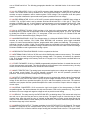
15.1.2 If the signal to be transmitted is a 0 - 20mA current source, the input pin must have a 250W resistor
placed between the pin and GROUND. The following table defines the characteristics of the input pin
working as a current input. Absolute limits defines the safe operating region. Operating outside this region
can damage the device. See below for an example of connecting a current loop sensor to the DATAFLOW
RTU.
7
PARAMET ER
INPUT RANGE
SOURCE IMPEDANCE
ABSOLUTE LIMITS
MINIMUM
0 mA
-8 mA
MAXIMUM
20 mA
(Ev-5)/.02 ohm
28 mA
15.2 All analog inputs are non-isolated. All analog measurements are referenced to GROUND. Take care
when connecting the DATAFLOW RTU to external sensors.
15.3 The user can invert the input state of a DATAFLOW RTU if desired, which will cause a DATAFLOW
RTU that reads an analog signal as full scale to transmit the signal status as a 0 scale to another
DATAFLOW RTU. This inversion allows a positive transfer function signal to control a negative transfer
function signal without external circuitry.
15.4 Sensor excitation voltage may be supplied by the DATAFLOW RTU using the J101 pin 5 Power Out
pin. For this configuration, make sure to not exceed the maximum current drive of the pin, and ascertain
your sensor will operate on a supply voltage of Vsupply-5Volts.
16. ANALOG OUTPUT S
16.1 The two analog outputs are defined to be pins 15 and 17. (NOTE: Pins 15 and 17 are outputs only if
PJ101 and PJ102 are configured as outputs.). These outputs are two low power outputs hardware
configured as either a voltage source or a current sink. All analog outputs are referenced to GROUND.
16.1.1 If the output pin is desired to be a voltage source, correctly set the hardware configuration. The pin is
to be hardware-configured as an output and as a voltage source. The following table defines the
characteristics of the output pin set as a voltage source. Attempting to drive a load less than the minimum
will cause incorrect output and possibly damage the device.
PARAMET ER
OUTPUT RANGE
LOAD RESISTANCE
MINIMUM
0V
1000 ohm
MAXIMUM
5V
16.1.2 If the output pin is desired to be a current sink, correctly set the hardware configuration. The pin is to
be hardware configured as an output and as a current source. The following table defines the characteristics
of the output pins set as a current sink. Attempting to drive a load less than the minimum will cause incorrect
output and possibly damage the device.
PARAMET ER
OUTPUT RANGE
LOAD RESISTANCE
MINIMUM
0 mA
MAXIMUM
20 mA
(Ev-5.5)/.02 ohm
16.2 The analog outputs can be programmed to have both initial and fail-safe conditions. The initial
condition forces the output to a desired state at power ON of the device. The fail-safe condition forces the
output to a desired state if a RF data link problem is detected. Refer to DATAFLOW RTU
Software/Programmers Manual for details on setting these conditions.
16.3 Meter excitation voltage may be provided by the DATAFLOW RTU using the Power Out pin 5 of
connector J101. If the Power Out pin is used as the excitation supply make sure that the maximum current
drive of the pin 5 is not exceeded and that your indicator will operate on a supply voltage of Vsupply5.5Volts.
16.4 It is not recommended to use the analog output as a warning indicator. If used, it is not available to be
mapped to the corresponding analog input of the other unit, meaning that a DATAFLOW RTU having an
analog output used in this manner can have only one analog signal sent to it. NOTE: Be sure to not exceed
the load drive capability if an analog output is used for a warning indicator.
17. T HEORY OF OPERATION
17.1 The DATAFLOW RTU control board performs many functions. It is used to program and control the
DTX RF board. It is the real-world interface for the telemetry inputs and outputs. It communicates to devices
8
over a RS-485 serial link. The following paragraphs describe how individual blocks of the control board
operate.
17.1.1 +5V REGULATOR: IC101 is a DC-to-DC converter which changes the VUNREG input voltage to
+5VDC. The +5VDC value is set by resistors R101, R102, and R103 with FB = 2.50V (pin 13). This IC also
contains an output comparator used to monitor system +5VDC voltage. This comparator shuts the system
down if low power is detected to prevent abnormal system operation due to low voltage.
17.1.2 VREG REGULATOR: IC112 is a DC-to-DC converter which changes the VUNREG input voltage to
+8.5VDC. The +8.5VDC value is set by resistors R148 and R149 with ADJ = 1.23V (pin 5). This IC also
contains an ENABLE pin (pin 1) which allows the microprocessor to turn this regulator ON and OFF. With
5V applied to the ENABLE pin, the regulator is ON; with 0V applied to the ENABLE pin, the regulator is
OFF.
17.1.3 4 Hz. INTERRUPT CLOCK: IC102 provides a 4 Hz. clock to the microprocessor, which functions as
an interrupt timer to make the microprocessor read all the digital and analog inputs. The 4 Hz. rate is made
by dividing the 32768 Hz. crystal (Y101). To save power, IC102 is not run at full +5V. Diodes CR103 and
CR104 are used to decrease the supply voltage to IC102.
17.1.4 MICROPROCESSOR. IC105 The microprocessor is a Motorola MC68HC705B16. This 8-bit MCU
contains an on-chip oscillator, CPU, RAM, ROM, EEPROM, A/D converters, pulse length modulated
outputs, I/O, serial communications interface, programmable timer system and watchdog. The processor is
running at a speed of 4 MHz. (Y102). The real world inputs are connected to the processor through PD0 PD5. PD6 is used to measure VUNREG voltage. Resistors R122 and R123 are used to scale this voltage.
PLMA and PLMB are used to generate the analog outputs.
17.1.5 DES ENCRYPTION PROCESSOR. IC106 is not placed at this time.
17.1.6 EXTERNAL RAM. IC108 is a 32,768 word x 8-bit CMOS static random access memory. This external
memory is used to store incoming and outgoing message traffic. This memory is backed-up by capacitor
C126. Q101 disables writing to the memory when the +5V supply is low. This prevents unwanted data to be
written to the RAM.
17.1.7 PORT EXPANDER. IC109 is a CHMOS programmable peripheral interface. It extends the amount of
I/O the microprocessor can handle. This chip connects the microprocessor to the external memory, the relay
drivers, the serial communications driver, and the RF board controls.
17.1.8 INPUT PROTECTION. The analog inputs are protected against over voltage and negative voltage as
well as being current limited. The circuitry between connector J101 and the processor provides this
protection. This circuitry should not change the incoming signal.
17.1.9 OUTPUT CONVERSION. PLMA and PLMB are used to generate the analog outputs. Connected to
each output is a two pole RC filter used to convert the pulse length modulation into a DC voltage. This DC
voltage is then fed into an operational amplifier (IC114) to add drive capability to the circuit. The resistors,
transistors, and jumpers after the operational amplifier are used to convert the output to either a voltage or a
current output.
17.1.10 SERIAL CONVERTER. IC110 converts the logic level signals of the microprocessor to RS-485
compatible signals. The devices between this chip and connector J105 are for protection only. They protect
the device from over voltage and negative voltage as well as provide current limiting.
17.1.11 RELAYS. The relays used by the DATAFLOW RTU are latching relays. This means each relay has
two coils, one to open the relay and one to close the relay. The signal to open or close the relay is a short
duration pulse. After this pulse the relay is "latched" in that state with no further current draw through the
relay coil. This allows reduced current draw by the DATAFLOW RTU. This also means that if power is lost to
the unit the relays stay in their last state.
17.1.12 MODULATION OUTPUT. The data modulation for the DATAFLOW RTU is Bi-Phase M. This output
modulation is produced by the microprocessor (IC105 pin 2) with a logic level amplitude (0 or 5 Volts).
Variable resistor R131 is used to scale this output causing the modulation level to be set. .The signal is then
9
passed through a low-pass filter (IC107) with a cut-off frequency of 1500 Hz. The purpose of this filter is to
round-off the edges of the square wave input.
17.1.13 MODULATION INPUT. The data modulation for the DATAFLOW RTU is Bi-Phase M. The received
data from the RF board is first run through a low-pass filter (IC107) to clean-up the wave. This signal is then
squared-up by a comparator (IC107). This signal is then finally decoded by a software decoder in the
microprocessor.
17.2 See the applicable RITRON DTX manual for the RF board theory of operation. When using the DTX
manual in support of the DATAFLOW RTU only the RF portion is valid. Disregard all references to the DTX
control board.
10