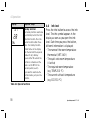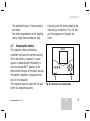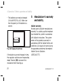
1
For the owner and heating engineer
Operating and Installation Manual
VRT 340f
Room temperature thermostat
GB
VRT 340f
Contents
Contents
Notes on the documentation . . . . . . 4
Storage of the documents .................... 4
Symbols used ........................................... 4
Safety . . . . . . . . . . . . . . . . . . . . . . . . . 5
4.1 Setting the operating modes ...... 9
4.2 Setting the current day and
time ................................................... 12
4.3 Setting the heating times ............ 13
4.4 Setting the room temperature ... 15
4.5 Activating special functions ........ 16
4.6 Info level ........................................... 18
4.7 Changing the battery .................... 19
Operating manual. . . . . . . . . . . . . . . . 6
1
Overview of the equipment . . . . . 6
2
Overview of the display . . . . . . . 7
3
Description of the appliance . . . 8
4
Operation. . . . . . . . . . . . . . . . . . . 8
2
5
Manufacturer’s warranty and
liability . . . . . . . . . . . . . . . . . . . .20
6
Recycling and disposal . . . . . . . . 21
Operating and installation manual VRT 340f
Contents
Installation instructions . . . . . . . . . .22
Notes on the installation and
operation . . . . . . . . . . . . . . . . . . .22
7.1 CE label ............................................. 22
7.2 Intended use.................................... 23
10 Electrical installation . . . . . . . . .28
10.1 Connecting the receiver ............... 29
7
Safety instructions and
regulations . . . . . . . . . . . . . . . . . 24
8.1 Safety instructions ........................ 24
8.2 Regulations ...................................... 25
11
11.1
11.2
11.3
Start-up . . . . . . . . . . . . . . . . . . . . 29
Installer level ................................... 31
Service/diagnostics level .............. 34
Handing over the appliance
to the owner .................................... 36
12
Troubleshooting . . . . . . . . . . . . . 37
13
Technical data . . . . . . . . . . . . . . . 38
14
Vaillant Service . . . . . . . . . . . . . 39
8
9
9.1
9.2
9.3
Installation . . . . . . . . . . . . . . . . . 25
Place of installation ....................... 25
Fitting the receiver ........................ 26
Mounting the room temperature
thermostat ....................................... 27
Operating and installation manual VRT 340f
GB
3
Notes on the documentation
Notes on the documentation
The following information is intended to
help you throughout the entire
documentation.
Other documents apply in combination
with this installation and operation
manual.
We accept no liability for any damage
caused by failure to observe these
instructions.
Storage of the documents
Please pass on this operating and
installation manual to the owner of the
system in order for him/her to store it so
4
that it is available whenever it is
required.
Symbols used
Please observe the safety instructions in
this manual for the installation of the
appliance.
Danger!
Immediate risk of serious injury
or death
Caution!
Potentially dangerous situation
for the product and environment.
Operating and installation manual VRT 340f
Notes on the documentation, safety
Note!
Useful information and
instructions.
• Symbol for a necessary task
Operating and installation manual VRT 340f
Safety
The room temperature thermostat must
be installed by a suitably qualified
heating engineer, who is responsible for
adhering to the existing standards and
regulations.
We accept no liability for any damage
caused by failure to observe these
instructions.
GB
5
1 Overview of the device
Operating manual
1
Overview of the equipment
1
2
Key
1 Display
2 Dial (turn and click)
I Info button
F Special functions button
P Programming key/installer level
Abb. 1.1 Overview of equipment
6
Operating manual VRT 340f
Overview of the display 2
2
Overview of the display
8
7
3
1
2
9
10
6
5
4
Key
1 Installer level and service/diagnostics level
2 Info level
3 Timer programming
4 Time/temperature display
5 Days of the week
6 Actual temperature
7 Operating modes
8 Special functions
9 Heating circuit symbol
10 Hot water symbol
Fig. 2.1 Overview of the display
Operating manual VRT 340f
GB
7
3 Device description, 4 Operation
3
Description of the
appliance
The VRT 340f is a room temperature
thermostat with a weekly heating
program for connecting to modulating
Vaillant boilers. The connection between
the room temperature thermostat and
the heating unit is by radio.
The VRT 340f enables you to specify the
room temperature using heating
programs. In addition, you can set the
special functions, such as the party
function, as well as the time control of a
hot water storage.
8
4
Operation
The operating principle is based on the
three buttons and an dial (Vaillant "turn
and click“ operating concept).
The display normally shows the current
operating mode (e.g. and ), or, if
activated, the respective special function
and the current room temperature, the
day of the week, the time and the
heating circuit symbol, if heating is
required.
Operating manual VRT 340f
Operation 4
4.1
Setting the operating modes
Table 4.1 provides you with an overview
of the operating modes you can select.
• When the room temperature
thermostat is in normal display mode.
press the dial once – the symbol for
the selected mode flashes in the
display.
• Turn the dial until the desired
operating mode appears on the
display.
The display switches back to normal
mode after five seconds.
Operating manual VRT 340f
GB
9
4 Operation
Symbol
10
Meaning
Heating
Automatic:
The operation of the heating circuit
changes between the operation modes
Heating and Energy Saving in
accordance with the time programme set
on the room temperature thermostat.
Heating:
The heating circuit is operated according
to the room temperature, regardless of the
programme set on the room temperature
thermostat.
Energy Saving:
The heating circuit is operated according
to the energy saving temperature "ECO“,
regardless of the programme set on the
room temperature thermostat.
Hot water
The operation of the hot water storage
cylinder changes between heating up and
OFF according to the time programme set
on the regulator.
The hot water symbol is displayed if the
time window is active.
Operating manual VRT 340f
Operation 4
Symbol
Meaning
Heating
Off:
Off:The heating circuit is off, provided that
the frost protection function (if the room
temperature is below 5°C) is not activated.
Hot water
The boiler is not heated up, regardless of
the set timer programme. The hot water
symbol is not displayed.
Table 4.1 Operating modes
Operating manual VRT 340f
GB
11
4 Operation
4.2
Setting the current day and
time
To set the current time and day of the
week with the display in normal mode,
you must perform the following steps:
• Press the dial until a day of the week
starts flashing.
• Turn the dial until you see the current
day of the week.
MO = Monday
TU = Tuesday
WE = Wednesday
TH = Thursday
FR = Friday
SA = Saturday
SU = Sunday
• Press the dial. The hours start flashing.
12
• Turn the dial until the required hour is
displayed.
• Press the dial. The minutes start
flashing.
• Turn the dial until the required minutes
are displayed.
The display switches back to normal
mode after five seconds.
If the calendar is activated on the
installer level, you can set the day,
month and year in the same way after
you set the time. This allows automatic
switching from winter to summer time.
Operating manual VRT 340f
Operation 4
4.3 Setting the heating times
The room temperature thermostat is
equipped with a basic program (see table
4.2).
You can adapt the default basic
programme to suit your needs.
There are five steps to setting the times
you want.
Time
window
Current day / Start
Block of days time
H1
M0 - FR
6:00
22:00
H2
—
—
—
1. Press the programming button P
2. Select the timer programme (heating
or hot water).
3. Select the time window
4. Select the current day or week block
5. Set the start time.
6. Set the end time.
End
time
H3
—
—
—
H1
SA
7:30
23:30
H2
—
—
—
H3
—
—
—
H1
SU
7:30
22:00
H2
—
—
—
H3
—
—
—
You can define three time windows for
each day.
Table 4.2 Default basic programme - heating
Operating manual VRT 340f
GB
13
4 Operation
For clarification, the individual steps are
shown again in the following table:
Display
Required steps
Press the programming
button P. The cursor (black
triangle) marks the value
which can be changed ( ),
which also flashes.
Turn the dial until the tap
symbol appears.
Press the dial. The cursor
marks the value which can
be changed (H1), which also
flashes.
Select the desired time
window by turning the dial.
Settings: H1, H2, H3
14
Display
Required steps
Press the dial. The cursor
marks the week block
display, which also flashes.
Select a block programme
or a single day of the week
by turning the dial.
Settings:
MO - SU
MO - FR
SA - SU
MO = Monday
TU = Tuesday
WE = Wednesday
TH = Thursday
FR = Friday
SA = Saturday
SU = Sunday
Operating manual VRT 340f
Operation 4
Display
Required steps
Press the dial. The cursor
marks the start time and the
hour display flashes.
Select the start time by
turning the dial. Press
the dial again to set the
minutes.
Press the dial. The cursor
marks the end time and the
hour display flashes.
Select the end time by
turning the dial. Press
the dial again to set the
minutes.
Table 4.3 Setting time windows
Operating manual VRT 340f
If necessary, you can switch the room
temperature thermostat from the week
programme to a daily programme.
• With the display in normal mode, press
the F button for about 10 seconds.
When you programme time windows,
days of the week will no longer be
displayed.
4.4 Setting the room temperature
The current room temperature is shown
in the basic display.
You can set the room temperature
directly from the basic display.
You can also set or change the set-back
temperature "ECO“ in the basic display.
GB
15
4 Operation
Setting the required room temperature
directly
• Turn the dial (with the display in
normal mode).
The set temperature display disappears,
the sun symbol is displayed in the
operating mode level and the set room
temperature is displayed in the multifunction level (e.g. TEMP 20 °C).
• You can set the required room
temperature directly (after about 1
second) to the desired value by turning
the dial.
The display switches back to normal
mode after five seconds.
16
Setting the set-back temperature
"ECO“
• Press the dial several times until ECO
appears in the multifunction display
along with a set value.
The set-back temperature is displayed
and starts flashing.
• Turn the dial until the required setback temperature is displayed (e.g.
ECO 15,0 °C).
The display switches back to normal
mode after five seconds.
4.5 Activating special functions
You can access the special functions
using the F button. You can activate the
following functions:
Operating manual VRT 340f
Operation 4
Display
Required steps
Quick veto
The quick veto function
allows you to adjust the room
temperature for a short time
(until the next time window).
Press the special function
button F - the quick veto
symbol appears in the display
along with the quick veto room
temperature.
Turn the dial until the quick
veto temperature you want is
displayed. The display switches
back to basic mode after 10
seconds and the function is
activated. To deactivate the
function, all you need to do is
press the F button.
Operating manual VRT 340f
Display
Required steps
Party function
When you activate the party
function the heating phase is
continued beyond the next setback phase. Press the special
function button three times
- the party symbol flashes in the
display for ten seconds and the
function is activated.
The function is deactivated
automatically by reaching the
next heating phase.
If you want to deactivate the
function before, just press the F
button. This function can only be
activated in automatic mode .
GB
17
4 Operation
Display
Required steps
Holiday function
The holiday function deactivates
the controller, but not the frost
protection function. Press the
special function button three
times - the holiday function
symbol flashes in the display.
Turn the dial until the required
number of day's holiday
appears. After 10 seconds the
function is activated and the
mode is set to OFF for the
selected period (see 4.1).
If you want to deactivate the
function before, just press the
F button.
4.6 Info level
Press the info button to access the info
level. The info symbol appears in the
display as soon as you open the info
level. Each time you press the button,
different information is displayed:
- The name of the room temperature
thermostat (VRT 340f )
- The quick veto room temperature
(if active)
- The required room temperature
(e.g. TEMP 20.0 °C)
- The current set-back temperature
(e.g. ECO 15.0 °C)
Table 4.4 Special functions
18
Operating manual VRT 340f
Operation 4
- The day/month/year (if the calendar is
activated)
- The timer programmes set for heating
(every single time window per day)
4.7 Changing the battery
The regulator checks the battery
condition itself, and the normal working
life of the battery is approx. 1.5 years.
Approx. 4 weeks before the battery is
fully discharged BATT appears in the
multifunction display of the basic display.
The battery chamber is located on the
back of the regulator.
The regulator must be taken off the wall
plinth to change the battery.
Operating manual VRT 340f
• Carefully push the locking hook to the
side using a screwdriver (Fig. 4.1) and
pull the regulator off towards the
front.
Fig. 4.1 Releasing the locking hook
GB
19
4 Operation, 5 Works guarantee and liability
• The batteries can now be changed
(2x AAA-LR03; Fig. 4.2). Make sure
that the polarity of the batteries is
correct.
Fig. 4.2 Changing the batteries
If the batteries are not changed in time,
the regulator switches over to operating
mode "Heating"
, to prevent the
installation from freezing up.
20
5
Manufacturer’s warranty
and liability
Vaillant warranty
We only grant a Vaillant manufacturers
warranty if a suitably qualified engineer
has installed the system in accordance
with Vaillant instructions. The system
owner will be granted a warranty in
accordance with the Vaillant terms and
conditions. All requests for work during
the guarantee period must be made to
Vaillant Service Solutions
(0870 060 777).
Operating manual VRT 340f
Recycling and disposal 6
6
Recycling and disposal
Both your Valliant room temperature
thermostat VRT 340f and its packaging
consist mainly of recyclable raw
materials.
Packaging
Please leave the disposal of the
transport packaging to the qualified
servicing company which installed the
appliance.
Appliance
Do not dispose of your Valliant room
temperature thermostat or any of its
accessories with the household waste.
Make sure the old appliance and any
accessories are disposed of properly.
Operating manual VRT 340f
GB
21
7 Information on installation and operation
Installation instructions
7
Notes on the installation
and operation
The assembly, electrical connection and
the settings in the device as well as the
commissioning must be carried out only
by a suitably qualified heating engineer.
Check the site of installation before
fitting the unit with regard to possible
radio interference by electrical
equipment or building influences which
may affect the functioning. If the radio
signal route is compromised then an
alternative installation site must be
chosen.
22
7.1
CE label
The CE label shows that the VRT 340f
room temperature thermostat, when
connected to Vaillant boilers, meets the
basic requirements of the Council of
Europe's directive 89/336/EEC on
electromagnetic compatibility and the
low voltage directive 73/23/EEC.
Installation instructions VRT 340f
Information on installation and operation 7
7.2
Intended use
The VRT 340f room temperature
thermostat is a state-of-the-art appliance
which has been constructed in
accordance with recognised safety
regulations. Nevertheless, there is still a
risk of death or serious injury to the user
or others or of damage to the device and
other property in the event of improper
use or use for which it is not intended.
The VRT 340f room temperature
thermostat is designed to control a
heating system with or without a hot
water system or circulation pump
according to time and location, in
connection with Vaillant modulating
heating equipment.
Installation instructions VRT 340f
The connection between the room
temperature thermostat and the heating
unit is by radio.
Any other use or extended use is
considered to be improper. The
manufacturer or supplier is not liable for
any resulting damage. The user alone
bears the risk.
Use includes observance of the
operating and installation manuals and
all other applicable documents, as well
as adherence to the maintenance and
inspection conditions.
Caution!
Any improper use is forbidden.
GB
23
8 Safety instructions and regulations
8
Safety instructions and
regulations
The unit must be installed by a suitably
qualified heating engineer, who is
responsible for adhering to the existing
standards and regulations. We accept no
liability for any damage caused by failure
to observe these instructions.
24
8.1
Safety instructions
Danger!
Risk of fatal electric shock from
touching live connections.
Before working on the appliance,
turn off the power supply and
secure against restart.
Only remove the room
temperature thermostat from
the wall mounting or from the
plinth when it is potential free.
Installation instructions VRT 340f
Safety instructions and regulations 8, Installation 9
8.2
Regulations
Use standard commercial cables for
wiring.
- Minimum cross-section of the wires:
0.75 mm2
The room temperature thermostat may
only be installed in dry rooms.
All wiring must be in accordance with
Building Regulations Part P and BS 7671
(IEE Wiring Regulations), and must be
carried out by a suitably qualified person.
Installation instructions VRT 340f
9
Installation
9.1
Place of installation
The room temperature thermostat must
be installed to ensure that it can
properly record the room temperature
(away from heat traps, not mounted on
cold walls etc.).
The best place for installation is usually
in the main living room on an inside wall
at approx. 1.5 m height. There, the room
temperature thermostat should able to
record the circulating air, unhindered by
furniture, curtains or other objects.
Choose a location where the room
temperature thermostat is not affected
by draughts from doors or windows,
GB
25
8 Safety instructions and regulations, 9 Installation
or by heat sources such as radiators,
chimney walls, televisions and direct
sunlight. All the radiator valves in the
room where the thermostat is installed
must be fully open.
• Push the receiver into the chute until
it clicks in position.
-2
9.2 Fitting the receiver
The connection of the receiver with the
heating unit is by a plug connector
having four connections.
• Remove the blanking plate (1) in the
front of the switchgear cabinet and
insert the receiver (2) into the chute
which is revealed so that the pins on
the back of the upper section fit into
the receptacles.
26
2
1
-2
-3
-3
VRC-VCC
VRC-VCC
1
0
2
3
bar
Fig. 9.1 Heating unit and fitting the receiver in
the switchgear box
Installation instructions VRT 340f
Installation 9
9.3
Mounting the room temperature
thermostat
Check the site of installation before
fitting the unit with regard to possible
radio interference by electrical
equipment or building influences which
may affect the functioning. If the radio
signal route is compromised then an
alternative installation site must be
chosen.
• Pull the room temperature thermostat
(1) off the wall plinth (3).
• Drill two holes (2) of 6 mm diameter
(as shown in fig. 9.2) and put in the
supplied wall plugs.
• Attach the wall plinth to the wall with
the two screws provided.
Installation instructions VRT 340f
• Insert the batteries supplied into the
battery compartment at the back of
the regulator (Fig. 9.2, Item 4). Make
sure that the polarity of the batteries
is correct.
GB
27
9 Installation, 10 Electrical installation
1
2
3
4
10 Electrical installation
The electrical connection may only be
carried out by a suitably qualified
heating engineer.
Danger!
Risk of fatal electric shock from
touching live connections. Before
carrying out work on the
controller, switch off the power
supply and secure it against
being switched on again.
Fig. 9.2 Mounting the room temperature
thermostat
28
Installation instructions VRT 340f
Electrical installation 10, Start-up 11
10.1 Connecting the receiver
The boiler is controlled via a four-core
connecting cable.
After correct insersion of the receiver
into the front of the switchgear box, the
room temperature thermostat is ready
for operation.
Also follow the instructions for the
boiler.
Do not remove the jumper between
terminals 3 and 4 on the boiler.
Installation instructions VRT 340f
11
Start-up
Certain system parameters have to be
set in order for them to comply with the
prevailing conditions.
These system parameters are all
together on one operating level and
should only be set by the heating
engineer.
The service/diagnostics level is also
intended for the engineer and is
designed to help during servicing.
The receiver is fitted with three status
LEDs which provides the following
information to the system:
GB
29
11 Start-up
LED Display Condition Function
green
ON
normal function
off
Fault (e.g. no power supply or fault see red LED)
no radio signal
OK
flashing No radio connection with the sender for more than one hour (e.g. poor
connection, weak battery in the sender...)
Operation in frost protection function:
- Hot water function switched on:
- Setting point for heating mode: 50 °C
red
yellow
off
normal function
flashing
Manual mode:
- Hot water function switched on
- Setting point for heating mode: 50 °C (the manual mode
automatically switches to normal mode if a correct radio connection is
made with the sender.
flashing
Radio connection is made with the sender
Table 11.1 Status display of the receiver
30
Installation instructions VRT 340f
Start-up 11
Use the button
to switch from
automatic to manual operation in the
event of a fault. The hot water system is
released and the feed temperature set
value for the heating is 50 °C. Manual
operation mode is retained until the next
time the radio signal is received.
Turn the dial to set the values you want.
When you press the P button the display
returns to basic mode.
11.1
Installer level
Press the P button to access the installer
level.
• Press the P button for approx. 10
seconds.
The spanner symbol and the first
parameter appear in the display.
• Press the dial. You can select all the
system parameters in turn.
Installation instructions VRT 340f
GB
31
11 Start-up
You can select and change the following
parameters:
Display
Set by turning the dial
Set-back temperature
Factory setting: 15 °C
Setting range: 5 ... 30° C
Correction of current room
temperature
Adjustment of the displayed
value by up to max.
+/- 3 °C
Factory setting: 0 °C
32
Display
Set by turning the dial
Two-point/analogue
operation
2-point/analogue mode
change-over.
The room temperature
thermostat is set in the
factory as a 2-point
regulation system (set
value 0). You can set it to
analogue mode by changing
the parameter to 1.
Installation instructions VRT 340f
Start-up 11
Display
Set by turning the dial
Control characteristics/
route adjustment
For optimum adaptation to
the room size or radiator
configuration
Factory setting: 0
Adjustment range: -5 ... +5
(positive values: slow
reaction speed of the room
temperature thermostat;
negative values: faster
reaction speed of the room
temperature thermostat)
Display
Set by turning the dial
Day setting
For activation of the
calendar
Month setting
For activation of the
calendar
Year setting
For activation of the
calendar
Table 11.2 System parameters
Installation instructions VRT 340f
GB
33
11 Start-up
11.2 Service/diagnostics level
Access the service/diagnostics level by
pressing the P button and the dial.
• Press the P button and the dial
simultaneously for approx. 3 seconds.
First, a heating request for 50 °C is
triggered to test communication with the
boiler. Then you can select all the test
options by pressing or rotating the dial.
When you press the P button the display
returns to basic mode.
34
Installation instructions VRT 340f
Start-up 11
You can select the following tests:
Dial
Press and
push P
button for 3
seconds.
Test
Heating request
Test procedure
A preset value of 50°C is simulated. The burner on the boiler
starts up and the pump starts (only up to the maximum supply
temperature of the boiler).
Press
Radio route
Display RF On
Press
Display test
All display elements are displayed.
Press
Software version
The software version is displayed.
Table 11.3 Service/diagnostic level
Installation instructions VRT 340f
GB
35
11 Start-up
Restoring the default settings
• To restore the controller to its default
condition, press the P button for 15
seconds.
11.3
Handing over the appliance to
the owner
The owner of the room temperature
thermostat must be instructed about its
functions and how to operate it.
• Hand over the manuals intended for
the owner as well as the documents of
the appliance.
• Go through the operating manual with
him and answer his questions.
36
• Draw special attention to the safety
instructions which the owner must
follow.
• Tell the owner to keep the manuals
near the room temperature
thermostat.
Installation instructions VRT 340f
Troubleshooting 12
12 Troubleshooting
The room temperature thermostat
signals the following fault conditions:
Fault signal
Meaning
Troubleshooting
RF Err
No radio connection to the radio
receiver on the heating unit
Check the site of installation
BATT
low battery condition, replacement
required
Replace the batteries.
Table 12.1 Fault signals
Installation instructions VRT 340f
GB
37
13 Technical data
13
Technical data
Description
Operating voltage
Maximum permissible ambient temperature
Battery working life
Transmission frequency
Transmission capacity
Current consumption
Minimum cross-section of the connection lines
Level of protection
Protection rating for regulator
Dimensions
Height/width/depth
Unit
V
°C
Months
MHz
mW
mA
mm2
mm
Sender
3V (2xAAA)
50
approx. 18
868,35
0,5
≤ 1 (readiness)
0,75
IP 20
III
Receiver
24
50
IP 20
III
97/146/27
85/148/30
868,35
≤ 15 (readiness)
Table 13.1 Technical data
38
Installation instructions VRT 340f
Vaillant Service 14
14 Vaillant Service
Vaillant Service
To ensure regular servicing, it is strongly
recommended that arrangements are
made for a Maintenance Agreement.
Please contact Vaillant Service Solutions
(0870 6060 777) for further details.
Installation instructions VRT 340f
GB
39
Kent ME2 4EZ
[email protected]
0020029346_00 GB 07 2006
Vaillant Ltd
Vaillant House
Medway City Estate
Trident Close
Rochester
Telephone 01634 292300
Fax 01634 290166
www.vaillant.co.uk