1
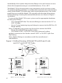
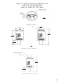
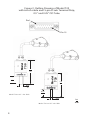
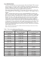
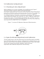
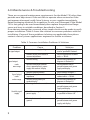
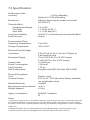
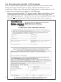
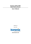
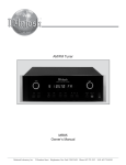
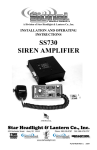
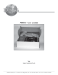
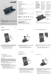
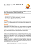
MODEL 730
CE and RoHS Compliant
OPERATING INSTRUCTIONS
1-800-257-3872 TOLL FREE
1-978-264-0292 FAX
[email protected] EMAIL
www.setra.com WEB
Setra offers a complete line of
products for these industries:
Industrial
HVAC
Test & Measurement
Barometric
Ultra High Purity/Sanitary
Vacuum
Contents
1.0 Introduction ..............................................................................................1
2.0 Mechanical Installation .........................................................................1
3.0 Electrical Installation ...............................................................................5
4.0 Operation ....................................................................................................7
5.0 Calibration and Adjustment of Zero Output.................................8
5. 1 Checking & Zero Adjustment .....................................................8
5. 2 Span (Full Scale) Adjustment and Calibration ...................9
6.0 Maintenance & Troubleshooting ......................................................9
7.0 Specifications......................................................................................... 10
8.0 Returning Products for Repair ....................................................... 11
9.0 Warranty & Limitation of Liability .................................................. 12
1.0 Introduction
Setra’s Model 730 capacitance manometer is a temperature compensated,
absolute pressure transducer designed for accurate and repeatable vacuum measurements. Various full scale ranges are available from 10 Torr up
to 1000 Torr. The units of measurement may be specified in Torr (mmHg),
mBar, kPa, or PSIA.
The Model 730 operates from a 12-30 VDC power supply and provides
a 0-10 VDC signal output that is linear with pressure and independent of
gas composition. It can also be supplied with a 0-5 VDC output, which
operates from 9-30 VDC power supply. The Model 730 is pin for pin
compatible with competitive capacitance manometers. Superior
EMI/RFI performance is achieved by the use of a metal case in conjunction with surge and ESD suppression components and RFI filtering on the
inputs and outputs. The Model 730 has easy access to multi-turn
potentiometers for fine zero adjustments. Inconel is used for all wetted
materials for compatibility with corrosive gases. A wide range of process
connections are available.
The high accuracy pressure sensing element used in the Model 730 is
Setra’s patented variable capacitance sensor. A centrally located
feedthrough
assembly supports a circular electrode in close proximity to the back surface of the diaphragm. Together, the electrode and diaphragm form a variable capacitor within a small reference vacuum chamber. As the pressure
increases, the diaphragm deflects and the gap between the electrode and
diaphragm reduces, causing an increase in the capacitance. This change in
capacitance
is detected and converted to a highly accurate linear DC electronic signal
by Setra’s high frequency precision diode bridge circuit.
Excellent zero stability and barometric insensitivity is achieved through
the patented sensor design. The Model 730 sensor contains no fragile or
complex parts as found in ceramic based capacitance manometers. The all
welded construction eliminates stability issues inherent in other designs
due to frictional contact between dissimilar materials.
2.0 Mechanical Installation
Remove all packaging material and the protective flange cover and visually
check the Model 730. If the Model 730 appears damaged, notify Setra Systems or your supplier immediately. Retain packaging materials for inspec1
tion. Do not use if damaged. If the Model 730 is not going to be used
immediately, then replace the protective flange cover and store in an area
where the temperature range is controlled between -20 to +85°C.
The Model 730 can be mounted in any orientation on the vacuum system.
To avoid the buildup of debris or condensable material in the measurement
cavity of the Model 730 (which may cause measurement errors), we recommend that you install the Model 730 vertically with the tube facing down.
Outline drawings showing the external dimensions are shown in Figure 1
(see below).
To connect the Model 730 to your system use the appropriate hardware
for the type of fitting:
•
Use a Swagelock® Ultra Torr vacuum fitting to connect to the O.5” or
0.25” OD tube.
• Use an O-ring/centering ring and clamp to connect to the NW16 or 25
flange options.
Note: A stepped O-ring carrier may be used to connect the NW16
flange to an NW10 flange on the system.
• Use a Male 4 VCR™ or 8 VCR™ Face Seal Fitting and sealing
gasket to connect to the female swivel 4 VCR™ or 8 VCR™ Style Face
Seal Fitting.
Note: Tighten fittings in accordance with the manufacturer’s
specifications.
Figure 1: Outline Drawing of Model 730 with 9-pin D-sub
and 0.5” and 0.25” OD Tube.
Pin 1
0.12
3.05
Pin 9
1.50
38.10
2.06
52
2.06
52
in.
mm
0.99
25
0.50
13
2
Model 730 w/0.5” dia. Tube
0.75
19
0.25
6
Model 730 w/0.25” dia. Tube
Figure 2: Outline Drawing of Model 730
with 5-pin Terminal Strip,
and 0.5” and 0.25” OD Tube.
Span
Zero
in.
mm
Pin 1
Mating Connector
.69
17
Pin I
1.50
38
3.41
87
3.05
77
0.99
25
in
mm
Model 730 w/0.5” dia. Tube
Mating Çonnector
Pin 1
3.17
80
0.75
19
Model 730 w/0.25” dia. Tube
3
Figure 3: Outline Drawing of Model 730
with 6-inch cable and15-pin D-sub Terminal Strip,
0.5” and 0.25” OD Tube.
Pin 1
3.24
82
Model
730
Model
730
Pin 15
0.99
25
3.0
76
0.50
13
Model 730 w/0.5” dia. Tube
0.75
19
0.25
13
Model 730 w/0.25” dia. Tube
4
in.
mm
3.0 Electrical Installation
The model 730 operates from a 12-30 VDC regulated power supply for
the 0-10 VDC output version or from a 9-30 VDC regulated power supply
for the 0-5 VDC output version. Either version can be specified with a 5 Pin
terminal strip, 9 Pin D-sub, or 15 Pin D-sub on a 6 inch pigtail. Mating connectors are provided with the terminal strip version. The pinouts for each
option are shown in figures 4, 5, and 6, Page 6.
The ground of any external power supply and readout system should be
the same as the transducer ground (chassis ground) to minimize any possible ground loops, which may effect the performance and stability of the
system.
3.1 Wiring Guidelines
The Model 730 is compliant with the Electro Magnetic Compatibility Directive 2004/108 EC, which tests for radio frequency emissions and immunity,
provided the following wiring guidelines are adhered to:
1. All interconnecting cables must have overall metal braid and foil
shields covering all wires and be properly grounded at each end.
2. The cable connectors must have a metal case and it must be in
direct contact with the cable braided shield for the entire circumference of
the cable. A single wire from the shield to the connector case will not be
effective.
3. The connectors must make good contact, about 0.01 ohms, to the
transducer’s case (chassis).
4. Versions with the 5 pin terminal strip connector option must be
used with a suitable clamp on ferrite such as the Fair-rite part number
0461164281 which is included with each unit. The ferrite should be assembled as close to the connector as possible to meet CE EMI requirements.
5
Fig. 4: Pin-out of 5-Pin
Terminal Strip
Fig. 5: Pin- out of D-sub
9-Pin Connector
Pin 1
0.12
3.05
Span
Zero
Pin 1
in.
mm
Pin 9
1.50
38.10
Pin Location
1
2
3
4
5
Pin 1
Function
+Signal Output
Power Supply Common
Power Supply + VDC
Signal Output Common
Not Used
Pin Location
1
9
4
8
2,3,5,6,7
Function
Power Supply Common
Signal Output Common
+Signal Output
Case Ground
Power Supply +VDC
Fig. 6: Pin-out of Cable Assembly D-sub
15-Pin Connector
Pin 15
Pin Location
2
5
7
12
15
Function
+Signal Output
Power Supply Common
Power Supply + 15 VDC
Signal Output Common
Chassis Ground
1, 3, 4, 6, 8, 9, 10, 11, 13, 14 Not Used
6
4.0 OPERATION
For most accurate pressure measurement, allow the Model 730 to warm
up for at least 15 minutes. After installation, periodically check the zero
output reading to verify correct output. Adjust the zero potentiometer if
incorrect (See Section 5 for zero adjustment instructions).
The signal output of the Model 730 is linear with pressure; e.g., for a 10
VDC FS Model 730, 10 VDC equals 100% FS output; 1 VDC equals 10% FS
output.
Table 1 indicates the lowest pressures recommended for reading and
pressure control for each range of the Model 730. The lowest suggested
pressure for reading is limited by the resolution and the accuracy of the
Model 730. This is directly related to the electrical noise on the signal
output and can be significantly effected by incorrect electrical ground
connection, or connection to an electronically noisy power supply or
readout instrument. Improved results may be obtained if the transducer
is operated in an environment with stable temperature and air flow. The
lowest recommended pressure used for control applications, such as a
closed loop downstream pressure control system, is based on a minimal
signal output of 50 mV.
Note 1: if the unit has been exposed to sudden environmental changes, allow at least 2 hours
before making any adjustments.
Table 1: Recommended Lowest Pressures
Available for Reading & Pressure Control
Recommended Lowest
Recommended Lowest
Full Scale Range
Pressure Reading
Pressure for Control
10 Torr
0.005 Torr
0.05 Torr
7
20 Torr
0.010 Torr
0.10 Torr
50 Torr
0.025 Torr
0.25 Torr
100 Torr
0.050 Torr
0.50 Torr
200 Torr
0.100 Torr
1.00 Torr
1000 Torr
0.500 Torr
5.00 Torr
10 mbar
0.005 mbar
0.05 mbar
100 mbar
0.05 mbar
0.5 mbar
1000 mbar
0.5 mbar
5 mbar
1 kPa
0.0005 kPa
0.005 kPa
2 kPa
0.0010 kPa
0.010 kPa
5 kPa
0.0025 kPa
0.025 kPa
10 kPa
0.0050 kPa
0.050 kPa
20 psia
0.0100 psia
0.100 psia
5.0 Calibration & Adjustment
5. 1 Checking & Zero Adjustment
After installation on a system, the Model 730 should be zeroed. Figure 7
shows the location of the zero adjustment potentiometer.
Note: Before making adjustments be sure to allow the Model 730 to warm up and
pump down sufficiently to the system base pressure. This time will vary depending
on range and system conductance. A minimum of 15 minutes is suggested.
Use a digital voltmeter to view the signal output of the Model 730. Adjust the
signal output of the Model 730 to be 0.001 to –0.001 V. Make this adjustment
at a pressure at least 1/2 decade below the Model 730’s resolution; e.g., for a
10 Torr FS unit the zero pressure should be less than 5E-5 Torr. For a 1000 Torr
unit, a pressure less than 0.050 Torr is acceptable.
Figure 7 : Location of Calibration Adjustment Potentiometers
0.12
3.05
1.50
38.10
5. 2 Span (Full Scale) Adjustment and Calibration
The Zero adjustment is the only adjustment that should be made in the field.
Span (Full Scale) adjustments require a calibrated and certified reference standard and should only be attempted by qualified personnel. Return the Model
730 to Setra Systems for periodic calibration, Span (Full Scale)
Adjustment and Calibration adjustments and servicing.
8
6.0 Maintenance & Troubleshooting
There are no general maintenance requirements for the Model 730 other than
periodic zero adjustment. If the unit fails to operate when received or if the
unit appears damaged, notify Setra Systems or your supplier immediately.
Retain packaging materials for inspection. Do not use if damaged. If the Model
730 is not going to be used immediately then replace the protective flange
cover and store in suitable conditions described in Section 2.
If no obvious damage has occurred, a few simple checks can be made to verify
proper installation. Table 2 shows the solution to common problems with the
installation. If none of these problems/solutions are applicable, then please
contact a Setra Systems applications engineer for further assistance.
Table 2: Common Installation Problems & Solutions
Problem
Cause
Incorrect or no supply voltage
No signal output
Readout display short circuit or
incorrect impedance
Incorrect wiring
Signal output
reads
over-range
Signal output
reads
under-range
Unstable signal
supply
9
Potential difference between
chassis ground of unit , power
supply and readout / display
Solution
Ensure power supply is
used as specified in Section 3.
Ensure impedance of readout
unit is > 10 kΩ
Ensure wiring conforms to
diagrams in Section 3.0
Ensure common chassis
ground between unit, power
supply and display.
Incorrect zero adjustment
Readout display incorrect
impedance
Incorrect wiring polarity to
readout display
Chassis ground not connected
Adjust zero per section 5.1
Ensure impedance of
readout unit is > 10 kΩ .
Ensure wiring conforms to
diagrams in Section 3.0
Ensure common chassis
ground between unit, power
supply and display.
Unstable or unregulated
power supply
Use a regulated power supply
as specified in Section 3.0.
Electrical noise on chassis
ground
Ensure common chassis
ground between unit, power
supply, and display.
7.0 Specifications
Performance Data:
Accuracy 1
Resolution:
± 0.5% of Reading
Optional ± 0.25% of Reading
Infinite. lmited only by output noise level
(≤0.005% FS)
Thermal effect:s
Compensated Range:
Zero Shift:
Span Shift:
Long Term Stability
Proof Pressure:
0 to +50°C
< ± 0.25% FS/50 °C
< ± 1.35% Rdg/50°C
±0.5% FS/Yr, excluding environmental effects
45 psia
Environmental Data:
Operating Temperature:
Storage Temperature:
0 to +80°C
-20 to +85°C
Electrical Data (Voltage):
Connectors:
Excitation/Output:
Output Load:
Power Consumption:
Time Constant:
EMC Performance:
9 Pin D-Sub, 15 Pin D-sub on 6” Pigtail, or
5 pinTerminal Strip
12 to 30 VDC for 0 to 10 VDC output
9 to 30 VDC for 0 to 5 VDC output
>10 KΩ load
< 200 mW
< 20 ms
Complies with EMC Directive 2004/108EC
Physical Description:
Case:
Vacuum Fittings:
Stainless steel
0.25” or 0.5” OD Tube; other fittings available;
see specification sheet
Wetted Materials2:
Inconel®
Measurement cavity volume3: <6.0 cc
Weight (approx):
<250 g
Agency Compliance
EU RoHS Compliant
CE
Notes:
1. Accuracy is expressed as % of reading. However, near Zero, the accuracy is limited by the resolution of the instrument. So, the accuracy is more correctly stated as the greater of ±0.5% reading
or ±0.01% of Full Scale.. (For the optional accuracy, this becomes the greater of ±0.25% reading or
±0.01% FS).
2. Wetted material is for 0.5” tube option only. Other flange options will add stainless steel.
3. Maximum cavity volume including the 0.5” OD tube volume of 0.26 in3 (4.28 cc).
8.0 Returning the Model 730 for Repair
Please contact a Setra application engineer (800-257-3872, 978-263-1400)
before returning unit for repair to review information relative to your
application. Many times only minor field adjustments may be necessary. If it
is necessary to return the unit, please us the following:
When returning the Model 730, please use the “Repair Order Return Form”
(example below) found on our website at http://www.setra.com/tra/repairs/pdf/webrepair.pdf. Note: If the form is not completely filled out, the
unit will not be repaired and will be returned at the owner’s expense.
11
Calibration Services
Setra maintains a complete calibration facility that is traceable to the National
Institute of Standards & Technology (NIST). If you would like to recalibrate or
recertify your Setra pressure transducers or transmitters, please call our Repair
Department at 800-257-3872 (978-263-1400) for scheduling.
9.0 Warranty & Limitation of Liability
SETRA warrants its products to be free from defects in materials and workmanship, subject to the following terms and conditions: Without charge,
SETRA will repair or replace products found to be defective in materials or
workmanship within the warranty period; provided that:
a) the product has not been subjected to abuse, neglect, accident, incorrect wiring not our own, improper installation or servicing, or use in
violation of instructions furnished by SETRA;
b) the product has not been repaired or altered by anyone except SETRA
or its authorized service agencies;
c) the serial number or date code has not been removed, defaced, or otherwise changed; and
d) examination discloses, in the judgment of SETRA, the defect in materials
or workmanship developed under normal installation, use and service;
e) SETRA is notified in advance of and the product is returned to SETRA
transportation prepaid.
Unless otherwise specified in a manual or warranty card, or agreed to in writing and signed by a SETRA officer, SETRA pressure and acceleration products
shall be warranted for one year from date of sale.
The foregoing warranty is in lieu of all warranties, express, implied or statutory, including but not limited to, any implied warranty of merchantability for
a particular purpose.
SETRA’s liability for breach of warranty is limited to repair or replacement, or
if the goods cannot be repaired or replaced, to a refund of the purchase price.
SETRA’s liability for all other breaches is limited to a refund of the purchase
price. In no instance shall SETRA be liable for incidental or consequential
damages arising from a breach of warranty, or from the use or installation of
its products.
No representative or person is authorized to give any warranty other than as
set out above or to assume for SETRA any other liability in connection with
12
SS730 Rev.A 07/29/2008
159 Swanson Road, Boxborough, MA 01719-1304
Tel: 800-257-3872/978-263-1400, Fax 978-264-0292
Email: [email protected], Web: www.setra.com