1
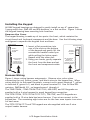
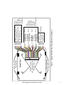
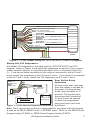
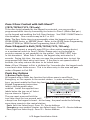
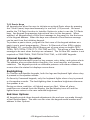
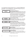
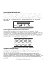
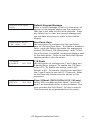
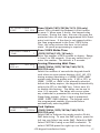
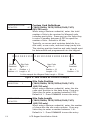
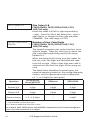
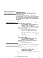
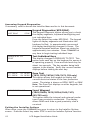
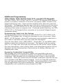
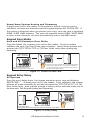
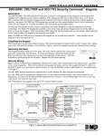
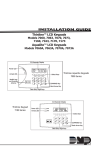
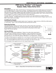
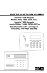
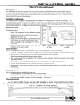
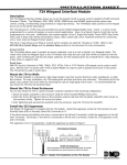
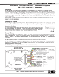
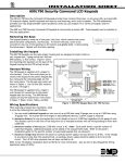
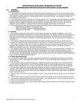
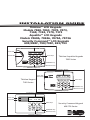
Installation Guide Thinline™ LCD Keypads Models 7060, 7063, 7070, 7073, 7160, 7163, 7170, 7173 Aqualite™ LCD Keypads Models 7060A, 7063A, 7070A, 7073A Security Command™ LCD Keypads 690/690F, 790/790F, 693/793 32-Character Display Power LED ABC PRINTING F R I 2 : 51 AM Armed LED Select Keys 1 2 3 4 5 6 7 8 9 0 CMD Thinline/Aqualite Keypads 7000 Series COMMAND Key Back Arrow Key Data Entry Digit keys 32-Character Display Power LED Armed LED ABC PRINTING F R I 2 : 51 AM Select Keys Thinline Keypad 7100 Series 1 2 3 5 6 7 9 0 4 8 CMD COMMAND Key Back Arrow Key Data Entry Digit keys 32-Character Display Power LED Armed LED ABC PRINTING F R I 2 : 51 AM R A R M E D Select Keys ! 1 ABC 5 MNO 9 2 D EF 6 P Q R 0 3 GH I 7 STU 4 8 V WX COMMAND YZ COMMAND Key Back Arrow Key Data Entry Digit keys Security Command Keypad 690/790 Series JKL © 2007 Digital Monitoring Products, Inc. Information furnished by DMP is believed to be accurate and reliable. This information is subject to change without notice. DMP Keypad Features The DMP Thinline™, Aqualite™, and Security Command™ LCD Keypads offer flexible features and functionality in stylish design choices. Each keypad provides: • Custom 16-character home or business name • Four 2-button Panic keys • AC power LED • Armed LED • 32-character display • Backlit keyboard with easy-to-read lettering • Internal speaker. • Keyboard and logo backlighting turns Red in alarm conditions • Simple harness connection to 4-wire keypad bus • Optional backboxes for conduit or wall-mount applications • The Thinline and Aqualite logo is also backlit. The Models 7070/7070A, 7073/7073A/7170/7173, 790/790F, and 793 keypads provide four fully programmable Class B, Style A protection zones you can program for a variety of burglary and access control applications. The Model 7063/7063A, 7073/7073A/7163/7173, and 693/793 keypads provide a built-in proximity card reader designed to read DMP/HID proximity credentials. The Model 7073/7073A/7173 and 793 keypads provide a door strike relay and allow Wiegand input from HID, DMP, or other external card readers. LCD Keypad Installation Guide 1 Installing the Keypad All DMP keypad housings are designed to easily install on any 4” square box, 3-gang switch box, DMP 695 and 696 backbox, or a flat surface. Figure 1 shows the keypad housing base mounting hole locations. Remove the Cover The keypad housing is made up of two parts: the front, which contains the circuit board and keyboard components and the base. Use the following steps and figures to separate the keypad front and base. Building Wall Thinline or Aqualite Keypad Lift screwdriver handle up toward you to separate keypad cover from base. 1. Insert a flat screwdriver into one of the slots on the bottom of the keypad and gently lift the screwdriver handle toward you while pulling the halves apart. Repeat with the other slot. 2. Using your hands, gently separate the front from the base and set the front and components aside. Building Wall Security Command Keypads Lift screwdriver handle up toward you to separate keypad cover from base. Harness Wiring Figure 1 shows wiring harness assignments. Observe wire colors when connecting the red, yellow, green, and black wires to the keypad bus. When wiring directly to the panel terminals, connect red to panel terminal 7, yellow to terminal 8, green to 9, and black to panel terminal 10. Use 1k Ohm EOL resistors, DMP Model 311, on keypad zones 1 through 4. The 7060/7060A, /7063/7063A/7160/7163, 690/690F, and 693 keypads are supplied with a 4-wire harness for panel keypad bus connection. The 7070/7070A, 7073/7073A/7170/7173, 790/790F, and 793 keypads are supplied with a 12-wire data bus/zone harness. Four wires connect to the keypad bus. The remaining eight wires are for the four zone inputs: two wires for each zone. The 7073/7073A/7173 and 793 keypads are also supplied with one 5-wire output/reader harness. 2 LCD Keypad Installation Guide LCD Keypad Installation Guide 3 Red/White White/Red Brown/White – Zone 1 White/Brown 1K EOL 1K EOL Black – Ground Green – Receive Data Yellow – Send Data Red – Keypad Power Orange White – Zone 3 White/Orange 1K EOL All Keypads – Zone 2 Yellow/White – Zone 4 White/Yellow 1K EOL External Reader/ Door Strike 7073/7073A 7173 and 793 Keypads Zones 1 through 4 7070/7070A, 7073/7073A, 7170/7173, 790/790F, and 793 Keypads Green/White – Connect Reader Data 0 White – Connect Reader Data 1 Orange – Door Strike Normally Open Gray – Door Strike Common Violet – Door Strike Normally Closed Figure 1: Keypad Back Showing Wiring Harness Assignments Surface and Backbox Mounting Holes Combined 4-square and 3-gang switch box Mounting Holes Keypad Back Surface and Backbox Mounting Holes Additional Power Supply If the current draw for all keypads exceeds the panel output, provide additional current by adding a Model 505-12 auxiliary power supply. Connect all keypad black ground wires to the power supply negative terminal. Run a jumper wire from the power supply negative terminal to the panel common ground terminal. Connect all keypad power (+12 VDC) wires to the power supply positive terminal. Do NOT connect the power supply positive terminal to any panel terminal. Refer to the 505-12 Power Supply Installation Guide (LT-0453) for more information. Keypad Bus Monitor For UL Listed fire protective systems, the 893/893A Module must be installed in the XR100/XR500 Series control panel to monitor the keypad bus and sound an audible trouble whenever the keypad bus fails to operate. Refer to the 893/893A Module Installation Sheet (LT-0135). Card Readers When a proximity credential is presented to an internal or external reader, a beep tone is heard and the Power and Armed LEDs blink. This provides both an audible and visual acknowledgement of the credential read. Internal Access Control Reader The 7063/7063A, 7073/7073A/7163/7173, and 793 keypads provide a builtin proximity card reader designed to read DMP/HID 1300 Series proximity credentials. Note: For UL Listed access control applications, the keypad must be installed within the protected area. External Access Control Reader To accept Wiegand data input from HID, DMP, or other external card readers, connect a 12 VDC external reader to the 7073/7073A/7173 or 793 keypad. Connect the Red and Black power wires from the reader to the power wires from the panel. These connect in parallel with the keypad power wires. Connect the Reader (Data 1) wire to the White wire on the 5-wire keypad harness. Connect the Reader (Data 0) wire to the Green/White wire on the 5-wire keypad harness. See Figure 2. Door Strike Relay Specifications (7073/7073A/7173, 793 only) The 7073/7073A/7173 and 793 keypads provide one internal Form C single pole, double throw (SPDT) relay for controlling door strikes or magnetic locks. Three wires on the 5-wire harness, Violet (N/C), Gray (Com), and Orange (N/O), allow you to connect devices to the relay. The Form C relay draws up to 15mA of current and its contacts are rated for 1 Amp at 30 VDC maximum. 4 LCD Keypad Installation Guide Green/White – Connect Reader Data 0 White – Connect Reader Data 1 Orange – Door Strike Normally Open Gray – Door Strike Common Violet – Door Strike Normally Closed Yellow/White 1K EOL White/Yellow – Orange White 1K EOL White/Orange– Zone 4 Zone 3 Request to Exit (option) Red/White – Zone 2 Door Contact (option) 1K EOL White/Red 1K EOL Brown/White – White/Brown Zone 1 7/0 Panic (option) Black – Ground Green – Receive Data Yellow – Send Data Red – Keypad Power External Card Reader To Keypad Bus Figure 2: 12 VDC Reader Wiring for 7073/7073A/7173 and 793 Keypads Wiring the 333 Suppressor One Model 333 Suppressor is included with the 7073/7073A/7173 and 793 keypads. Refer to Figure 3 and install the suppressor across the 5-wire output/ reader harness Common (C) and Normally Open (N/O) or Normally Closed (N/ C). If the device being controlled by the relay is connected to the N/O and C wires, install the suppressor on the N/O and C wires. If the device is connected to the N/C and C wires, install the 333 Suppressor on N/C and C wires. ���������������� ���������� ������������ �������� ������������ Door Strike Relay Operation ��� �������� ������ ������ ��������� ���������� ������������� As soon as the user code sent from the reader is verified by the panel, the keypad door strike relay activates for 5 ������ seconds. During this time, �������������� the access door connected ��������������� � � to Zone 2 must be opened ������������ ������������������ to start the programmed entry/exit timer and zone Figure 3: 5-wire Harness/Suppressor Installation Soft-Shunt. � ��� Note: The 5-second door strike is programmable in the panel when the keypad is used on an XR100/XR500 Series, or XR2500F panel. Refer to the XR100 Series Program Guide (LT-0896) or XR500 Series Program Guide (LT-0679). LCD Keypad Installation Guide 5 Zone 2 Door Contact with Soft-Shunt™ (7073/7073A/7173, 793 only) If the door being released by the keypad is protected, you can provide a programmed shunt time by connecting its contact to Zone 2 (White/Red pair) on the keypad and enabling the Soft-Shunt feature. See ZONE 2 SHUNT later in this document. Door contacts may be N/C or N/O. Note: The Door Strike time is programmable when the keypad is used on an XR100/XR500 Series, or XR2500F panel. Refer to the XR100 Series Programming Guide (LT-0896) or XR500 Series Programming Guide (LT-0679). Zone 3 Request to Exit (7073/7073A/7173, 793 only) You can also connect a normally open PIR (or other motion sensing device) or a mechanical switch to Zone 3 (White/Orange pair) on the keypad to provide a request to exit capability to the system. See ZONE 3 EXIT later in this document. When Zone 3 shorts, the keypad relay activates for 5 seconds. During this time, the user can open the protected door to start the programmed Soft-Shunt entry/exit timer. If the door is not opened within 5 seconds, the relay restores the door to its locked state. Note: A Zone 3 Request to Exit is inhibited for 3 seconds after the keypad reads a card and a door strike occurs. This is to allow entry to the area and pass under a Request-to-Exit PIR. Panic Key Options 2-Button Panic Keys All keypads offer a Panic key function that allows users to send Panic, Emergency, or Fire reports to the central station. In order to use the Panic keys, you must enable the Panic key function in the keypad user menu. See ������������������� Keypad Programming Instructions later in this document when enabled. Install the supplied icon labels below the top row of Select ������ ��������� ���� keys as shown in Figure 4. ���������������������� The user must press and hold the Figure 4: Panic Key Label Placement two Select keys for two seconds until a beep from the keypad is heard. At the beep, the panel sends the following zone alarm reports to the central station: Panic (left two Select keys)—Zone 19 + Device Address Emergency—non-medical (center two Select keys)—Zone 29 + Device Address Fire (right two Select keys)—Zone 39 + Device Address 6 LCD Keypad Installation Guide 7/0 Panic Keys All keypads also allow the user to initiate an optional Panic alarm by pressing the 7 and 0 (zero) keys simultaneously for one-half (1/2) second. You must enable the 7/0 Panic function in Installer Options in order to use the 7/0 Panic keys. See Keypad Programming Instructions later in this document. When enabled, all keypads send a Zone Short message to the panel for the first zone of the keypad address. When the keys are released a Zone Restore message can be sent from the initiating keypad. To produce a panic alarm, program the first zone of the keypad address as a panic type in panel programming. Place a 1k Ohm end-of-line (EOL) resistor, DMP Model 311, across the White/Brown pair of zone wires on models 7070/ 7070A, 7073/7073A/7170/7173, 790/790F and 793. This allows a Zone Restore message to be sent when the keys are released. The 1k Ohm EOL resistor is not required on 7060/7060A, 7063/7063A/7160/7163, or 690/690F keypads. Internal Speaker Operation All keypads emit standard tones for key presses, entry delay, and system alerts. The speaker also provides distinct burglary, fire, zone monitor, and prewarn cadences. The keypads provide an alternate prewarn with alarm cadence that occurs when the status list displays a zone alarm. Backlighting On Thinline and Aqualite keypads, both the logo and keyboard light when a key is pressed or the speaker sounds. On Security Command keypads, only the keyboard lights when a key is pressed or the speaker sounds. The backlighting dims to medium brightness whenever the speaker is on. During an alarm condition, all lighted areas turn Red. When all alarm conditions are cleared from the display, the Red display turns off and the lighted areas return to the user-selected brightness. End-User Options All keypads provide three keypad adjustments the end-user can make through a User Options Menu. The user can also view the keypad model number and address in User Options. LCD Keypad Installation Guide 7 On all keypads press and hold the Back Arrow (<—) and CMD (COMMAND) keys for two seconds to access User Options. The keypad display changes to SET BRIGHTNESS. Use the COMMAND key to display the next Option or press the Back Arrow to exit the User Options function. < < SET BRIGHTNESS SET TONE Set the keypad LCD Display brightness level, Power and Armed LEDs, and the Green keyboard and logo backlighting. Use the left Select key to lower the keyboard and logo brightness and the right Select key to raise the brightness. If the brightness level is lowered, it reverts to maximum intensity whenever a key is pressed. If no keys are pressed, and the speaker has not sounded for 30 seconds, the user-selected brightness level restores. Internal Speaker Tone > Set the keypad internal speaker tone. At the SET TONE display, use the left Select key to lower the tone and the right Select key to raise the tone. SET VOLUME LEVEL < > Internal Volume Level MODEL NUMBER 7073 V303 030805 Model Number KEYPAD ADDRESS 01 8 Backlighting Brightness > Set the keypad internal speaker volume level for key presses and entry delay tone conditions. During alarm and trouble conditions, the volume is always at maximum level. Use the left Select key to decrease the keypad volume and the right Select key to increase the volume. Press the COMMAND key to display the Model Number. The LCD displays the keypad model number and the keypad firmware version and date. The user cannot change this information in User Options. Keypad Address The LCD displays the current keypad address. While in User Options, the user cannot change the keypad address. Press the Back Arrow key to exit the User Options function. LCD Keypad Installation Guide Entering Alpha Characters To enter an alpha character, press the key that has the desired letter written below it. The keypad display shows the number on that key. To change the number to a letter, press the top row Select key that corresponds to the letter location under the key. For example, if you press key number 1, the letters for that key are A, B, and C. Press the first Select key for A, the second Select key for B, the third Select key for C, and the fourth Select key for special characters. A B C ( First Letter Third Letter Second Letter Special Character Figure 5: Entering Alpha Characters Entering Non-Alphanumeric Characters YZ 0 R * -. 8 ST I U L JK ? 7 PQ 4 GH X , 6 F ! 3 DE $ ) 2 # (s pa ce ) ' MN 9 O / AB 5 C ( 1 & Each key also has a special, non-alpha character you may use. These characters are not shown on the keypad. Enter a space by pressing 9 then the third Select key. The following non-alpha characters are available: ( ) ! ? / & $ ‚ (space) ’ starting with the left bracket on the 1 digit key to the blank space and apostrophe on the 9 digit key. Use the 0 digit key to enter - . * # (dash, period, asterisk, or number sign). See Figure 6. VW CMD Figure 6: Keys with Non-Alpha Characters Installer Options Menu All keypads provide Keypad Option and Keypad Diagnostic menus to allow installing and service technicians to configure and test keypad operation. Accessing Installer Options You can only access the Installer Options Menu through the User Options function. Hold down the Back Arrow and COMMAND keys for two seconds to display SET BRIGHTNESS. Enter the code 3577 (INST) and press COMMAND. The display changes to KPD OPT (keypad options) KPD DIAG (keypad diagnostics) and STOP. LCD Keypad Installation Guide 9 The Keypad Options menu allows you to set the keypad address, select Supervised or Unsupervised mode, change the default keypad message, selectively enable the 2-button Panic keys, Soft-Shunt, Request-to-Exit, and set entry card options. Note: All programming options display on all keypads, however, actual operation for some programming options is restricted to the listed keypads. Programming Keypad Options KPD KPD OPT DIAG Keypad Options (KPD OPT) STOP To program keypad options, press the left Select key under KPD OPT. The display changes to CURRENT KEYPAD ADDRESS: # #. CURRENT KEYPAD ADDRESS: 01 Keypad Address KEYPAD MODE: *SUP UNSUP Keypad Mode Set the keypad address from 01 to 05 with the XRSuper6 and XR20, from 01 to 08 with the XR40, XR100 and 01 to 16 with the XR500 Series and XR2500F. The factory default address is set at 01. To change the current address, press any Select key and then enter the new address using the appropriate number keys on the keyboard. It is not necessary to enter a leading zero for addresses 01 to 09. Configure the keypad for either Supervised or Unsupervised operation. Keypads with zones connected to them must be supervised. Supervised keypads cannot share addresses with other keypads. Unsupervised keypads can operate with other unsupervised keypads sharing the same address. Zones cannot be used on unsupervised keypads. To change the current setting, press the Select key under SUP or UNSUP. An asterisk appears next to the selected option. Note: Unsupervised addresses cannot be used when Device Fail Output has a programmed value other than zero. 10 LCD Keypad Installation Guide DEFAULT KEYPAD MSG: Default Keypad Message ARM PANIC KEYS: *PN *EM *FI Arm Panic Keys 7/0 PANIC ENABLE: 7/0 Panic Enter a custom message of up to 16 characters to appear on the keypad display top line whenever that line is not used for any other purpose. Press any Select key to clear the current message and use the data entry keys to enter a new custom display. Use this option to configure the top row Select keys as 2-button Panic keys. To enable or disable a Panic, press the Select key under the appropriate display: PN (Panic), EM (Emergency), and FI (Fire). Once the panic is enabled, an asterisk displays next to the description. Refer to the Panic Key Options section earlier in this document. NO YES ACTIVATE ZONE 2 SHUNT: NO YES Use this option to configure the 7 and 0 keys as a 2-button Panic feature. To enable the 7/0 Panic, select YES. To disable the option, select NO. Default is NO. To operate, simply press and hold the 7 and 0 keys for one-half (1/2) second. Refer to the Panic Key Options section earlier in this document. Zone 2 Shunt (7073/7073A/7173, 793 only) Select YES to enable the Soft-Shunt™ option on zone 2 as described earlier in this document. This zone provides the Soft-Shunt™ for door contacts. This zone must be programmed into the panel. LCD Keypad Installation Guide 11 Zone 2 Soft-Shunt Time ZONE 2 SOFTSHUNT TIME: 40 (7073/7073A/7173, 793 only) Enter the number of Soft-Shunt seconds to elapse before the Soft-Shunt timer expires. Range is from 20 to 250 seconds. Press any top row select key to enter the number of seconds. Once the door strike relay is activated, the user has 5 seconds to open the door connected to zone 2. The zone is then shunted for the programmed time or until the contact restores to normal. Ten seconds after the Soft-Shunt entry/exit time begins, the keypad beeps if the door is still open. If the door remains open when the timer expires a zone open/short is sent to the panel for Zone 2. The default is 40 seconds. Figure 7 shows how the Soft-Shunt works using the default 40 second timer. 5 Second Strike At 30 seconds, 40 the keypad beeps Seconds if door is still open. 40-Second "Soft-Shunt" and entry/exit timer. End of timer. A zone fault is indicated if door is still open. Figure 7: Door Strike Relay Operation Time Line RELOCK ZONE 2 FAULT: NO YES 12 Relock on Zone 2 Fault? (7073/7073A/7173, 793 only) Selecting NO leaves the relay on when Zone 2 faults to an open or short condition during Soft-Shunt. Selecting YES turns the relay off when Zone 2 faults open or short during Soft-Shunt. The default is NO. LCD Keypad Installation Guide ACTIVATE ZONE 3 EXIT: NO YES Zone 3 Exit (7073/7073A/7173, 793 only) ZN 3 REX STRIKE TIME: Zone 3 REX Strike Time ALL?: DELAY: 5 NO YES 2 Select YES to enable the Request to Exit feature on zone 3. When zone 3 shorts, the keypad relay activates. During this time, the user can open the protected door to start the programmed Soft-Shunt entry/exit timer. If the door is not opened within the time programmed in the Zone 3 REX Strike Time, the relay restores the door to its locked state. No panel programming is required. (7073/7073A/7173, 793 only) Enter the number of REX seconds to elapse. Range is from 5 to 250 seconds. Press any select key to enter the number. The default is 5 seconds. Arming/Disarming Wait Time (7063/7063A, 7073/7073A/7163/7173, 693/793 only) Select the number of seconds the keypad should wait when an area system displays ALL? NO YES during arming/disarming or a HOME/SLEEP/AWAY system waits during arming only. If NO or YES, or HOME, SLEEP, or AWAY is not manually selected before the delay expires, the keypad automatically selects the YES or the AWAY key. Select zero (0) to disable this feature. The delay can be one to nine (1-9) seconds. The delay also occurs when any credential is presented for arming the Home/ Sleep/Away system. After a card is presented, HOME SLEEP AWAY displays. The keypad waits the programmed number of seconds before automatically selecting AWAY. CARD OPTIONS DMP CUSTOM Card Options (7063/7063A, 7073/7073A/7163/7173, 693/793 only) Select DMP to indicate the reader sends a 26-bit DMP data string. To save the DMP option, press the left top row Select key under DMP. Default is DMP. Select CUSTOM if using a non-DMP credential. To select CUSTOM press the right top row Select key. LCD Keypad Installation Guide 13 WIEGAND CODE LENGTH: Custom Card Definitions 45 (7063/7063A, 7073/7073A/7163/7173, 693/793 only) When using a custom credential, enter the total number of bits to be received in Wiegand code including parity bits. Press any top row Select key to enter a number between 0-255 to equal the number of bits. Default is 45 bits. Typically, an access card contains data bits for a site code, a user code, and start/stop/parity bits. The starting position location and code length must be determined and programmed into the keypad. 011101011100110101000110011000101 First Bit Received Bit = 0 Position = 0 Site Code Bit = 1 Position = 1 Length = 10 User Code Bit = 0 Position = 11 Length = 20 Last Bit Received Bit = 1 Position = 33 In this example the Wiegand Code Length = 33 bits. Figure 8: Data Stream Bit Location Example SITE CODE POSITION: Site Code Position (7063/7063A, 7073/7073A/7163/7173, 693/793 only) 1 When using a custom credential, enter the site code start position in the data string. Press any Select key to enter a number between 0-255. Default is 1. Press COMMAND to save the entry. SITE CODE LENGTH: Site Code Length 1 (7063/7063A, 7073/7073A/7163/7173, 693/793 only) When using a custom credential, enter the number of characters the site code contains. Press any Select key to enter a number between 1-16. Default is 1. Press COMMAND to save the entry. 14 LCD Keypad Installation Guide USER CODE POSITION: User Code Position (7063/7063A, 7073/7073A/7163/7173, 693/793 only) 1 When using a custom credential, define the User Code start bit position. Press any Select key to enter a number between 0-255. Default is 1. Press COMMAND to save the entry. USER CODE LENGTH: User Code Length 45 (7063/7063A, 7073/7073A/7163/7173, 693/793 only) When using a custom credential, define the number of User Code bits. Press the fourth Select key to enter a custom number. Custom numbers can only be a number between 16-32. Press COMMAND to save the entry. The default is the DMP value of 45. REQUIRE SITE CODE: NO YES Require Site Code (7063/7063A, 7073/7073A/7163/7173, 693/793 only) Press the top row Select key under YES to use a site code and press COMMAND to view the site code entry display. Default is NO. In addition to User Code verification, door access is only granted when any one site code programmed at the SITE CODES entry option matches the site code received in the Wiegand string. You can program up to eight three-digit site codes. Note: A card with a site code greater than three digits cannot be used. Use only cards with threedigit site codes. SITE CODES 1-4 > > > > Site Codes 1-4 (7063/7063A, 7073/7073A/7163/7173, 693/793 only) Enter site codes 1-4 (left to right separated by > sign). Press the Select key below the > sign to add, delete, or change the site code and press COMMAND. Site code range is 0-999. Press the COMMAND key to display SITE CODES 5-8. LCD Keypad Installation Guide 15 Site Codes 5-8 SITE CODES 5-8 > > > > (7063/7063A, 7073/7073A/7163/7173, 693/793 only) Enter site codes 5-8 (left to right separated by > sign). Press the Select key below the > sign to add, delete, or change the site code and press COMMAND. Site code range is 0-999. NO OF USER CODE DIGITS: 5 Number of User Code Digits (7063/7063A, 7073/7073A/7163/7173, 693/793 only) The keypad recognizes user codes from four to six digits in length. Press any Select key to enter the user code digit length being used by the panel. Default is 5. When searching the bit string from the reader for the user code, the digits are identified and read from left to right. When a four-digit user code is selected only the first four digits of the string are read. The table below identifies the panel types, the required operating modes for the arming/disarming feature, and the appropriate code configuration (4, 5, or 6 digits) for each panel. Arms H/A Disarms H/A XR100/XR500 Series/XR2500F N/A 4-digit Arms A/P Disarms A/P N/A 4-digit N/A 4-digit N/A 4-digit Arms Area(s) Disarms Area(s) N/A 4, 5, or 6-digits — N/A 4-digit* Operation XRSuper6 XR20/XR40 4-digit 4-digit 4-digit 4-digit — * During entry delay only — Not available on this panel type N/A Requires additional selection to arm As of March 2005, XR500 Series and XR2500F Command Processor™ Panels recognize a user code with a maximum of six digits. 16 LCD Keypad Installation Guide Degraded Mode DEGRADED MODE RELAY ALWAYS OFF (7063/7063A, 7073/7073A/7163/7173, 693/793 only) This option defines the relay action when communication with the panel has not occurred for five seconds. Press any top row Select key to display CHOOSE ACTION. The default is Relay Always Off. CHOOSE ACTION OFF SITE ANY ON Choose the Degraded Mode Action required. Press the first Select key to choose OFF [Default] (Relay Always Off) — The relay does not turn on when any Wiegand string is received. Off does not affect any REX operation. Press the second Select key to choose SITE (Accept Site Code) — Door access is granted when the Wiegand site code string received matches any site code programmed at SITE CODE ENTRY. For details refer back to the REQUIRE SITE CODE option. Press the third Select key to choose ANY (Any Wiegand Read) — Door access is granted when any Wiegand string is received. Press the fourth Select key to choose ON (Relay Always On) — The relay is always on. CHOOSE ACTION LAST Press the COMMAND key to display the next action. Press the first Select key to choose LAST (Keep Last State) — The relay remains in the same state and does not change when communication is lost. After choosing the action, DEGRADED MODE and the newly defined action display. Programming is now complete. LCD Keypad Installation Guide 17 Accessing Keypad Diagnostics If necessary, refer to Access the Installer Menu earlier in this document. Keypad Diagnostics (KPD DIAG) KPD KPD OPT DIAG STOP The Keypad Diagnostic option allows you to check the display segments, keyboard backlighting and test individual keys. Press the Select key under KPD DIAG. The keypad lights all display segments and illuminates the keyboard in Red. In approximately one second the display backlighting changes to Green. The keypad alternates between these two states for approximately two minutes. Press COMMAND at any time to begin testing individual keys. PRESS KEY TO TEST Test Individual Keys Z1 OPEN Z3 OPEN Zone Test The display changes to PRESS KEY TO TEST. This option tests each key on the keyboard to ensure it is operating properly. Press and hold each key for about two seconds. The key number being held appears in the display. Verify the correct number displays before testing the next key. Z2 OPEN Z4 OPEN INPUT WIEGAND (7070, 7073/7073A/7170/7173, 793 only) This option allows the keypads to display the current electrical status of the four protection zones. The status is shown as OPEN, SHRT, or OKAY. Note: The Zone Test displays on other keypads, but is not operational. Input Wiegand (7063/7063A, 7073/7073A/7163/7173, 693/793 only) This option tests the internal and external reader input from proximity credentials. The display shows OKAY each time a good proximity read is received. Exiting the Installer Options When done, press the COMMAND key once to return to the Installer Options screen. Press the Select key under STOP to exit the Installer Options function. 18 LCD Keypad Installation Guide Additional Programming 7063/7063A, 7073/7073A/7163/7173, and 693/793 Keypads The 7063/7063A, 7073/7073A/7163/7173, and 693/793 keypads allow users to present a proximity credential to the built-in proximity reader located in the keypad backlit logo area. Users can also manually enter their user code into the keypad. The keypad verifies the user code and its authority with the panel. Additionally, the 7073/7073A/7173 or 793 activate the on-board Form C relay releasing a door strike or magnetic lock. To provide added flexibility, the 7073/ 7073A/7173 or 793 Keypads allow connection of an external Wiegand output compatible reader. Programming Cards into the System This programming feature operates on 7063/7063A/7163, 7073/7073A/7173, and 693/793 keypads only. Access the User Menu in one of two ways. When MENU? NO YES displays, choose YES and present your proximity credential to the reader or manually enter your user code into the keypad. From the User Menu, select USER CODES?. Choose ADD. At the ENTER CODE: display, present the credential to the reader. The keypad works by reading the 4, 5, or 6-digit user code from the data sent by the access control reader. For more information, refer to Entry Cards in the programming section of this document and the following User’s Guide section on adding, deleting, and changing user codes. Proximity Credentials Compatibility DMP Keypads with internal proximity readers are compatible with most standard 125Khz Prox credentials available from HID and all DMP proximity credentials. DMP Keypads are not compatible with iClass or other non-HID credentials. There are custom and non-standard credentials from HID that are not compatible with DMP proximity keypads. If you are using HID cards that have not been purchased directly from DMP, it is recommended to thoroughly test the application fully before installation. DMP does not guarantee compatibility with credentials not purchased from DMP. LCD Keypad Installation Guide 19 User’s Guide This User’s Guide covers 7063/7063A, 7073/7073A/7163/7173, and 693/793 keypads and contains three different sections: Keypad Arming and Disarming, Keypad Door Strike, and Keypad Entry Delay. All of the examples displayed assume that CLOSING CODE is YES in panel programming. Note: Figures 9 through 12 show the user presenting their card to the keypad. When an external reader is connected to a 7073/7073A/7173 or 793 keypad, the user presents their card to the reader rather than to the keypad. Keypad Arming and Disarming Area system Arming and Disarming Press COMMAND, the keypad displays ARM DISARM. Press the Select key under either option. The keypad displays ENTER CODE: -. Present your card to the keypad or to an external reader connected to the 7073/7073A/7173 or 793 keypad. Once validated by the system, all areas assigned to your code arm or disarm automatically and the 7073/7073A/7173 or 793 keypad Door Strike relay activates. ABC SECURITY ARM DISARM ABC SECURITY ENTER CODE: – ABC SECURITY ALL? NO YES Select NO to arm or disarm individual areas. Select YES, or simply wait, to automatically arm or disarm all areas for which you are authorized. Figure 9: Area Arming and Disarming All/Perimeter System Arming and Disarming Present your card to the reader or press COMMAND, the keypad displays DISARM? or PERIM ALL PERIM ALL or (when arming). Press the DISARM? Select key under the desired option. The keypad displays ENTER CODE: -. Present your card to the reader. Once validated by the system, the The system arms or disarms the areas and selected areas arm or disarm activates the door strike relay on the 7073, 7073A or 793 keypad. automatically. On 7073/ Figure 10: All Perimeter Arming and Disarming 7073A/7173 or 793 keypads, the Door Strike relay then activates. 20 LCD Keypad Installation Guide Home/Away System Arming and Disarming Present your card to the reader. If the system is armed, once the card is validated, all areas are disarmed and the keypad displays ALL SYSTEM OFF. If the system is disarmed when you present your card, once the card is validated, HOME SLEEP AWAY displays. The user can manually select HOME, SLEEP, AWAY or after a short timeout, all areas automatically arm in the AWAY mode. Keypad Door Strike Area and All/Perimeter Door Strike From the Status List, present your card to the reader. Once the system validates the card, the Door Strike relay activates. Home/Away systems only activate the 7073/7073A/7173 or 793 Door Strike relay when arming and disarming. ABC SECURITY MON 10:20 AM While the keypad displays the Status List, present your access card. Typically, the relay activates for 5 seconds during which time you can open the door. Once you open the door, you have 40 seconds to exit and close the door before the Zone 2 Soft-Shunt expires. Figure 11: Present Access Card Keypad Entry Delay All Systems Once the entry delay starts, the keypad sounds an entry tone and displays ENTER CODE: - . Present your card to the reader. Once validated, the system disarms all areas accessible by you and activates the 7073/7073A/7173 or 793 Door Strike relay. Area systems provide a delay to allow selected areas only to be disarmed. See Keypad Arming and Disarming. ABC SECURITY ENTER CODE: – Entry delay starts. The System disarms the area and activates the Door Strike Relay. Figure 12: Entry Delay LCD Keypad Installation Guide 21 FCC Information This device complies with Part 15 of the FCC Rules. Operation is subject to the following two conditions: (1) This device may not cause harmful interference, and (2) this device must accept any interference received, including interference that may cause undesired operation. Changes or modifications made by the user and not expressly approved by the party responsible for compliance could void the user’s authority to operate the equipment. NOTE: This equipment has been tested and found to comply with the limits for a Class B digital device, pursuant to part 15 of the FCC Rules. These limits are designed to provide reasonable protection against harmful interference in a residential installation. This equipment generates, uses and can radiate radio frequency energy and, if not installed and used in accordance with the instructions, may cause harmful interference to radio communications. However, there is no guarantee that interference will not occur in a particular installation. If this equipment does cause harmful interference to radio or television reception, which can be determined by turning the equipment off and on, the user is encouraged to try to correct the interference by one or more of the following measures: - Reorient or relocate the receiving antenna. - Increase the separation between the equipment and receiver. - Connect the equipment into an outlet on a circuit different from that to which the receiver is connected. - Consult the dealer or an experienced radio/TV technician for help. 22 LCD Keypad Installation Guide Wiring Specifications When planning a keypad bus installation, keep in mind the following specifications: 1. DMP recommends using 18 or 22-gauge unshielded wire for all keypad and LX-Bus circuits. Do Not use twisted pair or shielded wire for LX-Bus and keypad bus data circuits. To maintain auxiliary power integrity when using 22-gauge wire do not exceed 500 feet. When using 18-gauge wire do not exceed 1,000 feet. Install an additional power supply to increase the wire length or add devices. 2. Maximum distance for any one circuit (length of wire) is 2,500 feet regardless of the wire gauge. This distance can be in the form of one long wire run or multiple branches with all wiring totaling no more than 2,500 feet. As wire distance from the panel increases, DC voltage on the wire decreases. 3. Maximum number of devices per 2,500 feet circuit is 40. Note: Each panel allows a specific number of supervised keypads. Add additional keypads in the unsupervised mode. Refer to the panel installation guide for the specific number of supervised keypads allowed. 4. Maximum voltage drop between the panel (or auxiliary power supply) and any device is 2.0 VDC. If the voltage at any device is less than the required level, add an auxiliary power supply at the end of the circuit. When voltage is too low, the devices cannot operate properly. Refer to the LX-Bus/Keypad Bus Wiring Application Note (LT-2031) for more information. Also see the 710/710F Module Installation Sheet (LT-0310). LCD Keypad Installation Guide 23 24 100mA 87mA + 2mA per active zone 100mA + 2mA per active zone 84mA 84mA + 2mA per active zone 120mA + 2mA per active zone 120mA + 2mA per active zone 85mA 72mA + 1.6mA per active zone 85mA + 1.6mA per active zone 77mA 77mA + 1.6mA per active zone 92mA + 1.6mA per active zone 92mA + 1.6mA per active zone 7063/7063A/7163 7070/7070A/7170 7073/7073A/7173 690/690F 790/790F 693 793 87mA 72mA 7060/7060A/7160 ALARM CURRENT NORMAL/ STANDBY CURRENT MODEL LCD Keypad Installation Guide X X X X X FOUR ZONES X X X X X X INTERNAL WIEGAND PROX INPUT READER X X INTERNAL FORM C DOOR STRIKE RELAY Keypad Specifications Specifications Operating Voltage 12 VDC Thinline/Aqualite Dimensions 7” W x 5.25” H x 0.5” D Security Command Dimensions 6.5” W x 5” H x 1” D Compatibility All keypads are compatible with all DMP Command Processor™ panels. Listings and Approvals Underwriters Laboratories (UL) Listed UL 365 Police Connected Burglar UL 609 Local Burglar UL 1023 Household Burglar UL 1076 Proprietary Burglar UL 1610 Central Station Burglar UL 1635 Digital Burglar UL 985 Household Fire Warning UL 864 Fire Protective Signaling California State Fire Marshall (CSFM) New York City (MEA) IC Registration ID: 5251A-PC0086 FCC Part 15 RFID Reader FCC ID: CCKPC0086 — Thinline and Aqualite FCC Part 15 RFID Reader FCC ID: CCK793 — Security Command Accessories Backboxes 695 or 696 Keypad Backbox 777 protective keypad cover Keypad Wiring Harness 300 4-wire harness 300-12 12-wire harness 330 4-wire dual end harness Proximity Credentials 1306P Prox Patch™ 1326 HID ProxCard II® Card 1346 HID ProxKey II® Access Device 300-5 5-wire harness 300-512 12-wire harness, 5 ft. long 1306PW Prox Patch™ 26-Bit 1351 HID ProxPass® Card 1386 HID ISOProx II® Card Proximity Readers for 7073/7073A/7173 and 793 keypads PP-6005B ProxPoint® Plus 30mA Standby 75mA Peak MP-5365 MiniProx™ 20mA Standby 110mA Peak PR-5455 ProxPro II® 25mA Standby 125mA Peak MX-5375 MaxiProx® 200mA Standby 700mA Peak TL-5395 Thinline™ II® 20mA Standby 115mA Peak LCD Keypad Installation Guide 25 Keypad Shortcut Keys Your LCD keypad provides one-button shortcut keys. Holding down a keypad button for two seconds until the tone re-sounds allows you to arm, monitor or reset your system. These options can still be accessed through the User Menu if desired. Sensor Reset (Fire Reset) Away All Monitor (Chime) 1 AB 5 9 C O MN YZ 2 F DE 6 PQ 0 R 3 GH 7 ST 4 I L JK 8 U VW Home X CMD Perimeter Sleep Keypad Shortcut Keys Keypad Key Press Key 1 Press Press Press Press Press Key Key Key Key Key 2 3 5 6 7 Arming System Operation Arm Away for Home/Sleep/Away systems Arm All for All/Perimeter systems Sensor (Fire) Reset on all systems Arm Home for Home/Sleep/Away systems Monitor (Chime) on all systems Arm Perimeter for All/Perimeter systems Arm Sleep for Home/Sleep/Away systems LT-0883 1.01 7401