1
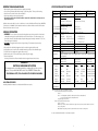
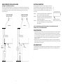
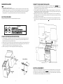
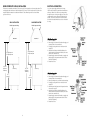
Viking Installation Guide
Viking Range Corporation
111 Front Street
Greenwood, Mississippi 38930 USA
(662) 455-1200
For product information,
call 1-888-VIKING1 (845-4641)
or visit the Viking Web site at
vikingrange.com
Electric Ranges/Rangetops
F1485L EN
(021808J)
IMPORTANT: PLEASE READ AND FOLLOW
•
•
•
•
•
SPECIFICATIONS-ELECTRIC RANGETOP
Before beginning, please read these instructions completely and carefully.
Do not remove permanently affixed labels, warnings, or plates from product. This may void the warranty.
Please observe all local and national codes and ordinances.
Please ensure that this product is properly grounded.
The installer should leave these instructions with the consumer who should retain for local inspector’s use
and for future reference.
Installation must conform with local codes or in the absence of codes, with the National Electrical Code, ANSI/NFPA
70-latest edition. In CANADA: Electrical installation must be in accordance with the current CSA C22.2 Canadian
Electrical Codes Part 1 and/or local codes.
GENERAL INFORMATION
1.
2.
3.
4.
5.
6.
7.
WARNING: The use of cabinets for storage above the appliance may result in potential fire or burn hazard.
Combustible items may ignite, metallic items may become hot and cause burns. If a cabinet storage is to be
provided the risk can be reduced by installing a rangehood that projects horizontally a minimum of 5” (12.7 cm)
beyond the bottom of the cabinets.
WARNING: This appliance shall not be used for space heating. This information is based on safety
considerations.
All openings in the wall behind the appliance in the floor under the appliance shall be sealed.
Keep appliance area clear and free from combustible materials, gasoline, and other flammable vapors.
Disconnect the electric supply to the appliance before servicing.
When removing oven for service and/or cleaning, disconnect AC power supply.
Electrical requirements:
Listed in specifications chart. Electrical installation should comply with national and local codes.
WARNING!!!
ELECTRICAL GROUNDING INSTRUCTIONS
This rangetop must be electrically grounded in accordance with local codes or, in the
absence of codes, with the National Electrical Code, ANSI/NFPA 70-latest edition.
FOR PERSONAL SAFETY, THIS APPLIANCE MUST BE PROPERLY GROUNDED.
BACK TRIM ACCESSORIES
Assembly and installation instructions are included with all back trim accessories.
Description
VERT301-4B
Overall Width
Overall Height
29 7/8” (75.9 cm)
BASE HEIGHT
To top of
glass frame - 7 7/8” (20.0 cm)
ADDITIONS TO BASE HEIGHT
To top of island trim add 1 1/4” (3.2 cm)
To top of backguard add 6” (15.2 cm)
To top of high-shelf add 23 1/2” (59.7 cm)
Overall Depth from To end of:
DERT301-4B
DERT361-5B
29 7/8” (75.9 cm)
BASE HEIGHT
To top of
side trim - 6 1/8” (15.6 cm)
35 7/8” (91.1 cm)
add 0” (0 cm)
add 6” (15.2 cm)
add 23 1/2” (59.7 cm)
Rear
side panel 24” (61.0 cm)
24 7/16” (62.1 cm)
control panel - 25 15/16” (65.9 cm)
26 1/8” (66.35 cm)
knobs 27 7/16” (69.7 cm)
27 5/8” (70.2 cm)
Cutout Width
30” (76.2 cm)
30” (76.2 cm)
36” (91.4 cm)
Cutout Height
7 1/2” (19.1 cm)
5 3/4” (14.6 cm)
5 3/4” (14.6 cm)
Cutout Depth
24” (61.0 cm)
24 7/16” (62.1 cm)
24 7/16” (62.1 cm)
Electrical Connection 40 amp
40 amp
50 amp
Requirements
3-Wire, 240/208 VAC, 60 Hz. Unit is equipped with No. 10 ground wire in conduit. Should be
fused separately.
Maximum Amps
240V- 34.6 amps
240V- 35.0 amps
240V- 45.0 amps
Surface Elements
Left Front
Bridge
Left Rear
Center
Right Front
Bridge
Right Rear
Approximate
Shipping Weight
208V- 29.8 amps
208V- 30.3 amps
208V- 40.0 amps
240V
208V
1500 watts
1125 watts
N/A
N/A
2400 watts
1800 watts
N/A
N/A
1800 watts
1350 watts
800 watts
600 watts
1800 watts
1350 watts
110 lbs. (49.5 kg)
240V
208V
1800 watts
1350 watts
800 watts
600 watts
1800 watts
1350 watts
N/A
N/A
1500 watts
1125 watts
N/A
N/A
2500 watts
1875 watts
52 lbs. (23.4 kg)
240V
208V
1800 watts 1350 watts
800 watts 600 watts
1800 watts 1350 watts
2700 watts 2025 watts
1500 watts 1125 watts
N/A
N/A
2200 watts 1650 watts
63 lbs. (28.4 kg)
Minimum clearances from adjacent combustible construction
•Cooking surfaces and below (36”[91.4 cm] and below)
•Sides- 0”
•Rear- 0” with backguard or highshelf; 0” with island trim and non-combustible wall;
6” (15.2 cm) with island trim and combustible rear wall
•Top grate support - 36” (91.4 cm)
•Above cooking surface (above 36”[91.4 cm])
•Sides- 6” (15.2 cm)
•Within 6” (15.2 cm) side clearance, wall cabinets no deeper than 13” (33.0 cm) must be minimum 18” (45.7 cm)
above cooking surface.
•Wall cabinets directly above product must be minimum 36” (91.4 cm) above cooking surface
It is not recommended to install two or more units side by side.
2
3
SPECIFICATIONS - ELECTRIC RANGE
PROXIMITY TO SIDE CABINET INSTALLATION
Description
VESC306-4B
Overall Width
Overall Height from Bottom
29 7/8” (75.9 cm)
Base Height
To top of glass frame - Min. 35 7/8” (91.1cm) to Max. 37 5/8” (95.6 cm)
[Legs adjust 1 3/4” (4.5cm)]
1. This rangetop may be installed directly adjacent to existing 36” (91.4 cm) high base cabinets. IMPORTANT: The
top grate support MUST be 3/8” (.95 cm) above the adjacent base cabinet countertop.
2. The rangetop CANNOT be installed directly adjacent to sidewalls, tall cabinets, tall appliances, or other side vertical
surfaces above 36” (91.4 cm) high. There must be a minimum of 6” (15.2 cm) side clearance from the rangetop to
such combustible surfaces above the 36” (91.4 cm) counter height.
3. Within the 6” (15.2 cm) side clearance to combustible vertical surfaces above 36” (91.4 cm) , the maximum wall
cabinet depth must be 13” (33.0 cm) and wall cabinets within this 6” (15.2 cm) side clearance must be 18” (45.7 cm)
above the 36” (91.4 cm) high countertop.
4. Wall cabinets above the rangetop must be a minimum of 36” (91.4 cm) above the rangetop cooking surface for the
full width of the rangetop. This minimum height requirement does not apply if a rangehood is installed over the
cooking surface.
Overall Depth from Rear
Electrical Requirements
Maximum Amp Usage
Preheat Rating
Surface Element Rating
Broil Rating
Bake Rating (partial power from
broil element
Convection Cook Rating
Oven Interior Dimension
Approximate Shipping Weight
Additions to Base Height
To top of island trim - add 1 1/4” (3.2 cm)
To top of backguard - add 6” (15.2 cm)
To top of high shelf - add 23 1/2” (59.7 cm)
To end of side panel 24 5/16” (61.8 cm)
To end of control panel 26 1/4” (66.7 cm)
To end of knobs 27 3/4” (70.5 cm)
240-208/120 VAC/60Hz - Connect with locally supplied 3-wire, flexible cord
rated 60 amp 125-250 minimum. Cord must be agency approved for use with
household electric ranges.
240V - 58.5 amps
208V - 50.7 amps
240V - 24.0 amps
208V - 20.8 amps
240V
Left Front
1500 watts
Left Rear
2400 watts
Right Front
1800 watts
Bridge
800 watts
Right Rear
1800 watts
240V
Maxi Broil - (8 Pass)
3000 watts
Mini Broil - (4 Pass)
1250 watts
A
240V - 2935 watts
240V - 2200 watts
Width 23” ( 58.4 cm)
Height 16 1/8” (41.1 cm)
Depth 15 3.8” (39.1 cm)
Overall size - 3.3 cu. ft.
424 lb. (190.8 kg.
Minimum clearances from adjacent combustible construction
•Cooking surface and below (36” [91.4 cm ] and below)
•Sides - 0”
•Rear - 0” with backguard or high shelf; 0” with island trim and non-combustible rear wall; 6” (15.2 cm) with
island trim and combustible rear wall.
•Top grate support - 36” (91.4 cm)
•Above cooking surface (above 36” [91.4 cm])
•Sides - 6” (15.2 cm)
•Within 6” (15.2 cm) side clearance, wall cabinets no deeper than 13” (33.0 cm) must be minimum 18” (45.7 cm)
above cooking surface.
•Wall cabinets directly above product must be minimum 36” (91.4 cm) above cooking surface
•Use range only with factory supplied legs.
4
B
VERT
DERT
A
7 1/2”
19.1 cm)
5 3/4”
(14.6 cm)
B
24”
(61.0 cm)
24 7/16”
(62.1 cm)
ELECTRICAL REQUIREMENTS
Check your national and local codes regarding this unit. This rangetop is supplied with a 3 wire conduit which is
equipped with a No. 10 ground wire. See next section for grounding instructions. This unit should be fused
separately. CAUTION: Be sure the electrical power is off from the breaker box to the junction box until the unit is
installed and ready to operate. The junction box should be located as shown in the drawing and connected to a
suitable ground.
5
WOOD/COMPOSITE OVERLAY INSTALLATION
ELECTRICAL CONNECTION
(Including Custom Ventilator Installation)
With the rangetop positioned in front of the cabinet opening, connect the wire
leads extending from the conduit to the junction box, making sure the neutral
(white) wire is connected to the appropriate terminal. Check your local codes to
see which of the options below should be used in grounding the unit. Do not
use GFI circuit.
The bottom of a standard hood should be 30” (76.2 cm) min to 36” (91.4 cm) max above the ceramic glass surface.
This would typically result in the bottom of the hood being 66” (167.6 cm) to 72” (182.9 cm) above the floor. Refer to
the rangehood installation instructions for further information. These dimensions provide for safe and efficient
operation of the hood.
WALL INSTALLATION
ISLAND INSTALLATION
Wood/Composite Overlay
Wood/Composite Overlay
OPTION 1
OPTION 2
OPTION 3
Metal Hood
Metal Hood
Connnect the neutral (white) wire and the grounding (bare) wire
with the incoming neutral (white) power supply lines.
If the junction box is grounded, untwist the grounding (bare) wire
and attach to the junction box. Attach the neutral (white) wire to
neutral (white) power supply line.
Untwist the grounding (bare) wire and attach it to a suitable
ground. Attach neutral (white) wire to the incoming neutral (white)
power supply line.
Identification Label Location (bottom of unit in left rear corner)
DO NOT USE AN EXTENSION CORD WITH THIS APPLIANCE. SUCH USE MAY RESULT IN A FIRE,
ELECTRICAL SHOCK, OR OTHER PERSONAL INJURY.
FINAL PREPARATION
1. Some stainless steel parts may have a plastic protective wrap which must be peeled off. All stainless steel body
parts should be wiped with hot, soapy water and with a liquid cleaner designed for this material. If build-up
occurs, do not use steel wool, abrasive cloths, cleaners, or powders!! If it is necessary to scrape stainless steel to
remove encrusted materials, soak with hot, wet cloths to loosen the material, then use a wood or nylon scraper.
Do not use a metal knife, spatula, or any other metal tool to scrape stainless steel! Scratches are almost
impossible to remove.
2. The interior of the oven should be washed thoroughly with hot, soapy water to remove film residues and any
installation dust or debris before being used for food preparation, then rinsed and wiped dry. Solutions stronger
than soap and water are rarely needed.
30” (76.2 cm) min
36” (91.4 cm) max
30” (76.2 cm) min
36” (91.4 cm) max
REPLACEMENT PARTS
66” - 72”
(167.6 cm 182.9 cm)
Countertop
Countertop
66” - 72”
(167.6 cm 182.9 cm)
36”
(91.4 cm)
Only authorized replacement parts may be used in performing service on the range. Do not repair or replace any
part of the appliance unless specifically recommended in the manual. All other servicing should be referred to a
qualified technician.
36”
(91.4 cm)
6
7
RANGE INSTALLATION
PROXIMITY TO SIDE CABINET INSTALLATION
Legs
1. This range may be installed directly adjacent to existing 36” (91.4 cm) high base cabinets. IMPORTANT: The top
grate support MUST be 3/8” (.95 cm) above the adjacent base cabinet countertop. This may be accomplished by
raising the unit using the adjustment spindles on the legs.
2. The range CANNOT be installed directly adjacent to sidewalls, tall cabinets, tall appliances, or other side vertical
surfaces above 36” (91.4 cm) high. There must be a minimum of 6” (15.2 cm) side clearance from the range to such
combustible surfaces above the 36” (91.4 cm) counter height.
3. Within the 6” (15.2 cm) side clearance to combustible vertical surfaces above 36” (91.4 cm) , the maximum wall
cabinet depth must be 13” (33.0 cm) and wall cabinets within this 6” (15.2 cm) side clearance must be 18” (45.7 cm)
above the 36” (91.4 cm) high countertop.
4. Wall cabinets above the range must be a minimum of 36” (91.4 cm) above the range cooking surface for the full
width of the range. This minimum height requirement does not apply if a rangehood is installed over the cooking
surface.
1. Legs are packed in styrofoam top pack.
2. Legs should be installed near to where the appliance is to be used, as they are not secure for long transit. After
unpacking the range, raise it about a foot to remove the bottom shipping skid. Keep the unit raised to permit the
legs to be screwed into their couplings and lower it gently to keep any undue strain from the legs and internal
mounting hardware. It is strongly recommended that a pallet or lift jack be used rather than tilting.
BACK TRIM ACCESSORIES
Assembly and installation instructions are included with all back trim accessories.
WARNING
•THIS RANGE CAN TIP
•INJURY TO PERSONS COULD RESULT
•INSTALL ANTI-TIP DEVICE PACKED WITH RANGE
•SEE INSTALLATION INSTRUCTIONS
36” Minimum
(91.4 cm)
STABILITY DEVICE INSTALLATION INSTRUCTIONS
1. The anti-tip bracket is to be attached to the rear wall as shown. The dimension for the bracket location from the
floor is to be determined after the range legs have been adjusted to the proper installation height shown in the
installation instructions and the range has been leveled.
2. Measure from the floor to the bottom of the anti-tip opening located on the back of the range. Measured Dim. (A).
3. Locate the anti-tip bracket on the wall with the top left corner at the measured dimension plus 1/2” from the floor
and the 5-5/8” from where the left side of the range (facing range) is to be located.
4. Slide the range into place. Be sure the anti-tip bracket slides into the anti-tip opening.
6” Minimum
(15.2 cm)
13” Maximum
(33.0 cm)
30” (76.2 cm)
0”
18” Minimum
(45.7 cm)
3/8” (.95 cm)
36”
(91.4 cm)
0”
Anti-tip Bracket
Adjustable Legs
ELECTRICAL REQUIREMENTS
Check your local codes regarding this unit. This range requires 3 wires, 240-208/120 VAC, 60 Hz. See next section for
grounding instructions. It should be fused separately. CAUTION: Be sure the electrical power is off from the breaker
box to the junction box until the range is installed and ready to operate. The junction box should be located as shown
in the drawing and connected to suitable ground. Do not use GFI circuit.
8
9
WOOD/COMPOSITE OVERLAY INSTALLATION
ELECTRICAL CONNECTION
The bottom of a standard hood should 30” (76.2 cm) min to 36” (91.4 cm) max above the ceramic glass surface. This
would typically result in the bottom of the hood being 66” (167.6 cm) to 72” (182.9 cm) above the floor. Refer to the
rangehood installation instructions for additional information. These dimensions provide for safe and efficient
operation of the hood.
Use a 3-wire power supply cord kit rated for 60 amps 125/250 volts with closed loop terminals and marked for use
with ranges. Where local codes do not permit grounding
through neutral, use a 4-wire power supply cord. the cord or
conduit must be secured to the range with the strain relief
bracket. The electrical connection is made at the terminal
block, which is located behind the access door on the back of
the range.
WALL INSTALLATION
ISLAND INSTALLATION
Wood/Composite Overlay
Wood/Composite Overlay
Metal Hood
Metal Hood
30” (76.2 cm) min
36” (91.4 cm) max
30” (76.2 cm) min
36” (91.4 cm) max
66” - 72”
(167.6 cm 182.9 cm)
66” - 72”
(167.6 cm 182.9 cm)
Countertop
36”
Countertop
36”
(91.4 cm)
(91.4 cm)
10
3-Wire Power Supply Cord
1. Remove access door.
2. Remove supply cord strain relief bracket and 3-supply cord
mounting screws on the terminal block.
3. Feed supply cord up thru the hole in the bottom of the
range back.
4. Attach the line #1 (red) and line #2 (black) leads to the
outside terminal and the neutral wire (white) to the center
terminal on the terminal block.
5. Reattach supply cord strain relief bracket over supply cord,
pushing supply cord up toward terminal block to relieve
strain before tightening.
6. Reattach access door.
4-Wire Power Supply Cord
1. Remove access door.
2. Remove supply cord strain relief bracket and 3-supply cord
mounting screws on the terminal block.
3. Remove grounding screw; cut-off and discard ground strap.
4. Feed supply cord up thru the hole in the bottom of the
range back.
5. Attach the ground lead (green) with the ground screw that
was removed in step #3.
6. Attach the line #1 (red) and line #2 (black) leads to the
outside terminal and the neutral wire (white) to the center
terminal on the terminal block.
7. Reattach supply cord strain relief bracket over supply cord,
pushing supply cord up toward terminal block to relieve
strain before tightening.
8. Reattach access door.
11
ELECTRICAL CONNECTION WITH CONDUIT
IMPORTANT: LEVELING/ADJUSTMENTS/ALIGNMENT
Use 1/2” (1.3 cm) trade size conduit with a conduit clamp, 12
AWG/600 volt copper conductor colored red for line 1 and black
for line 2 and 14 AWG/600 volt copper conductor colored white
for neutral with closed loop terminals marked for use with ranges.
Where local codes do not permit grounding through neutral, use a
green 12 AWG copper conductor as directed in the 4-wire
connector directions. The conduit must be secured to the range
with the strain relief bracket. The electrical connection is made at
the terminal block which is located behind the access door on the
back of the range.
Closely follow the procedures below to ensure proper performance and appearance of the range.
3-Wire Power Connection
1. Remove access door.
2. Remove strain relief mounting angle and reattach as shown.
3. Feed 1/2” (1.3 cm) trade size conduit through the hole in the
bottom of the range back and secure to the strain relief bracket
with a conduit clamp.
4. Feed line #1 (red 12 AWG/600v copper conductor), line #2
(black 12 AWG/600v copper conductor) and neutral (white 14
AWG/600v copper conductor) through conduit and attach
closed loop terminals marked of use with range.
5. Remove 3 mounting screws and attach line #1 (red) to the left
terminal line #2 (black) to the right terminal, the neutral wire
(white) to the center terminal.
1. If the floor is smooth and level, level the unit with the screw thread of the legs. Set the high corner of the range so
that the the top of the grate support is 3/8” (.95cm) above the countertop, and level the range to the high corner.
2. If the floor is uneven or has a decided slope, level the unit with metal shims, as the adjustment required may exceed
the thread available in the leg.
3. After the range is properly leveled, the drip tray handle may be aligned by loosening the screws and adjusting the
handle horizontally within the limits provided by the slotted screw holes.
4. A level should be placed across the top of the range and the unit leveled both front-to-back and side-to-side. If it is
not level, burner combustion may be erratic, liquid, or semi-liquid batters will cook at an angle, and the unit may
not function efficiently.
Identification Label Location
(located behind door)
A. Right Side
Front / Back
Adjustable Legs
6. Reattach the access door.
B
4-Wire Power Connection
1. Remove access door.
2. Remove strain relief mounting angle and reattach as shown.
3. Feed 1/2” (1.3 cm) trade size conduit through the hole in the
bottom of the range back and secure to the strain relief bracket
with a conduit clamp.
4. Feed line #1 (red 12 AWG/600v copper conductor), line #2
(black 12 AWG/600v copper conductor), neutral (white 14
AWG/600v copper conductor) and grounding wire (green 12
AWG copper conductor) through conduit and attach closed
loop terminals marked of use with range. (Terminal is not
required on grounding wire if used with ground washer.
5. Remove 3 mounting screws and green grounding screw. Cut
off and discard ground strap. Attach line #1 (red) to the left
terminal, line #2 (black) to the right terminal, the neutral wire
(white) tothe center terminal and the copper ground wire to the
green grounding screw using the ground washer.
6. Reattach the access door.
12
A
B. Left Side
Front / Back
Adjustable Legs
All ranges are tested before leaving the factory. When the range is connected to the electrical service, the installer
should use the “Performance Checklist” for his final checks.
When adjustments are required, contact your dealer/installer for corrections. If assistance is not available, contact
Viking Range Corporation Preferred Service for the nearest authorized service agent at (888) 845-4641. All corrections
to installation are the responsibility of the dealer/installer or end user.
13
PERFORMANCE CHECKLIST
The installer should carry out the following performance checks. Refer to instructions below.
1. Check top surface elements - glow red when turned on.
2. Check hot surface indicator lights - glow red when corresponding element is on.
3. Check oven bake function - bake element on full power.
Convection bake function - bake element is same with the convection fan on.
4. Check convection cook function - convection cook element (behind fan cover) on and convection fan on.
5. Check mini broil function - center broil element on.
6. Check maxi broil function - center and outside broil elements on. Convection broil function is the same as maxi
broil with the convection fan on.
7. Check self-clean function - door will lock and in approximately 30 seconds; the center and outside broil elements
will turn on. Check broil elements through window to make sure they are on, then abort self-clean cycle to unlock
door.
CAUTION: Do not run self-clean cycle for more than 10 minutes with oven racks and rack supports inside oven.
This could cause them to discolor due to the high temperature required for self-cleaning.
FINAL PREPARATION
1. Some stainless steel parts may have a plastic protective wrap which must be removed. The interior of the oven
should be washed thoroughly with hot, soapy water to remove film residues and any installation dust or debris
before being used for food preparation, then rinsed and wiped dry. Solutions stronger than soap and water are
rarely needed.
2. All stainless steel body parts should be wiped with hot, soapy water and with a liquid cleaner designed for this
material. If buildup occurs, do not use steel wool, abrasive cloths, cleaners, or powders! If it is necessary to scrape
stainless steel to remove encrusted materials, soak with hot, wet cloths to loosen the material, then use a wood or
nylon scraper. Do not use a metal knife, spatula, or any other metal tool to scrape stainless steel! Scratches are
almost impossible to remove.
Any adjustments necessary that are a result of the installer not following instructions will be the responsibility of the
installer, dealer, or the end user of the product.
REPLACEMENT PARTS
Only authorized replacement parts may be used in performing service on the range. Do not repair or replace any part
of the appliance unless specifically recommended in the manual. All other servicing should be referred to a qualified
technician.
14
15