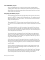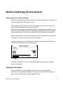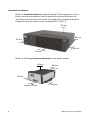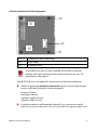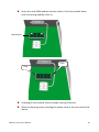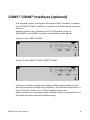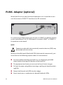
1
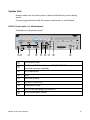
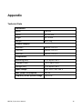
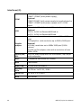
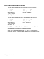
BEETLE /X plus Modular POS System User Manual We would like to know your opinion on this publication. Please send us a copy of this page if you have any constructive criticism. We would like to thank you in advance for your comments. With kind regards, Your opinion: Wincor Nixdorf International GmbH Technical Documentation RD HWD01 Wohlrabedamm 31 D-13629 Berlin E-Mail: [email protected] Order No.: 01750235902A BEETLE /X plus Modulare POS System User Manual Edition September 2012 All brand and product names mentioned in this document are trademarks of their respective owners. Copyright © Wincor Nixdorf International GmbH, 2012 The reproduction, transmission or use of this document or its contents is not permitted without express authority. Offenders will be liable for damages. All rights, including rights created by patent grant or registration of a utility model or design, are reserved. Delivery subject to availability; technical modifications possible. Contents Manufacturer’s Certification .....................................................................1 Tested Safety ................................................................................................ 1 FCC-Class A Declaration ................................................................................ 1 Safety Notes .................................................................................................. 2 Important Notes ........................................................................................... 2 Introduction ..............................................................................................4 About This Manual ........................................................................................ 4 Care Of BEETLE /X plus.................................................................................. 5 Recycling the BEETLE /X plus ........................................................................ 5 Warranty ....................................................................................................... 6 Before Switching On the System ...............................................................7 Unpacking And Checking the System ....................................................... 7 Setting Up the Device ................................................................................... 7 Horizontal Installation .............................................................................. 8 Vertical Installation Of the Equipment ..................................................... 9 Cabling Of the BEETLE /X plus ..................................................................... 10 POS System BEETLE /X plus ..................................................................... 12 Front Side View ........................................................................................... 12 USB (Universal Serial Bus)- A, USB 2.0.................................................... 12 Power Button ......................................................................................... 13 Light-emitting Diode (LED) ..................................................................... 13 Interior View ............................................................................................... 14 Connector Panels .................................................................................... 15 Power Supply .............................................................................................. 15 Power Connector.................................................................................... 16 System Unit ................................................................................................. 17 BEETLE /X plus with a J1- Motherboard ................................................. 17 RJ10/RMT Jack (optional) ....................................................................... 18 D- Sub Plug (COM1) ................................................................................ 18 D- Sub- Jack Power Supplied (COM2*-COM4*) ..................................... 18 DisplayPort (DP) ..................................................................................... 18 DVI-I ........................................................................................................ 19 Mini- DIN (KYBD) .................................................................................... 19 USB (Universal Serial Bus)- A .................................................................. 19 RJ45 (LAN) ............................................................................................... 19 Jack Plug 3.5 mm (IN/OUT/MIC) ............................................................. 20 RJ12 (CASHDR) ........................................................................................ 20 Disconnecting Cables.............................................................................. 21 Storage Media ........................................................................................ 23 Change Of the Hard Disk Drive .................................................................... 23 RAM Modul ............................................................................................ 28 USB- Hub (optional) ............................................................................... 30 COM5*-COM8* Interfaces (optional) ..................................................... 31 PLINK- Adapter (optional) ...................................................................... 32 Starting Up the System ........................................................................... 33 Appendix ................................................................................................ 35 Technical Data ............................................................................................. 35 Interfaces (J1) .............................................................................................. 36 Wall Mounting System ................................................................................ 37 Wall Mounting Power Supply...................................................................... 38 Total Current Consumption Of Interfaces ................................................... 39 Abbreviations ......................................................................................... 40 Manufacturer’s Certification The device complies with the requirements of the EEC directive 2004/108/EC with regard to ‘Electromagnetic compatibility" and 2006/95/EG “Low Voltage Directive”. Therefore, you will find the CE mark on the device or packaging. Tested Safety The POS system BEETLE /X plus has been provided with the symbol for “Tested Safety”. In addition, the BEETLE /X plus has received the UL symbol and cUL symbol. FCC-Class A Declaration This equipment has been tested and found to comply with the limits for a Class A digital device, pursuant to part 15 of the FCC Rules. These limits are designed to provide reasonable protection against harmful interference when the equipment is operated in a commercial environment. This equipment generates, uses, and can radiate radio frequency energy and, if not installed and used in accordance with the instruction manual, may cause harmful interference to radio communications. Operation of this equipment in a residential area is likely to cause harmful interference in which case the user will be required to correct the interference at his own expense. Modifications not authorized by the manufacturer may void users authority to operate this device. This class A digital apparatus complies with Canadian ICES-003. Cet appareil numerique de la classe A est conforme à la norme NMB-003 du Canada. BEETLE /X plus User Manual 1 Safety Notes The device may only be repaired by authorized qualified personnel. Unauthorized opening of the device and inexpertly carried-out repairs may not only seriously jeopardize the safety of the user, but also cancel all warranty and liability agreements. Expansion cards with electrostatically sensitive devices (ESD) can be marked with this sticker. Important Notes The modular POS system BEETLE /X plus conforms to the current safety standards for data processing equipment. If this device is taken from a cold environment into the operating room, moisture condensation may form. The device must be absolutely dry before being put into service; an acclimatization period of at least two hours must therefore be observed. This device is equipped with a safety-tested power cable and may be connected only to a prescribed grounded-contact power socket. When setting up the device, ensure that the power socket on the device and the grounded-contact power socket are easily accessible. To disconnect the device from the supply voltage completely, switch off the device and disconnect the power plug of the system. Ensure that no foreign objects (e.g. office clips) find their way into the device, as this may lead to electric shocks or short-circuits. The ventilation slots of the power supply must remain unobstructed to ensure sufficient ventilation of the equipment. If the equipment is to be fitted, you must ensure that the specified minimum distances are maintained and constant ventilation is provided. Never plug in or unplug data communication lines during thunderstorms. Protect devices from vibrations, dust, moisture and heat. Always dispose of used parts, such as batteries, in an environmentally safe manner. 2 BEETLE /X plus User Manual In emergencies (e.g. damaged housing or damaged power cable, penetration by liquids or foreign bodies), the device must be switched off immediately, the power plug disconnected and the Customer Service of Wincor Nixdorf or your dealer must be notified. The lithium battery must be disposed of in accordance with local regulations for special waste. In case of an improper change of the lithium battery it exist an explosion risk. Your BEETLE system is the result of modern technical innovation. So please see for according structural and technical surroundings to guarantee a faultless and efficient work of your BEETLE. Therefore, you should connect your BEETLE or other IT-devices only to power supply systems with separately guided protective earth conductor (PE). This kind of electricity system is known as TN-S network. Do not use PEN conductors! Please also observe the recommendations of the norm DIN VDE 0100, Part 540, Appendix C2 as well as EN50174-2, §5.4.3.Thus you can help to avoid possible mal functions. You can connect or disconnect USB devices during operation of your BEETLE, provided that these devices comply with the specifications according to usb.org. Other peripheral devices with higher power requirement (such as PoweredUSB printer) should be connected to or disconnected from your BEETLE system only after the BEETLE has been switched off. If you replace a storage medium, make sure that you only use the storage medium recommended or approved by Wincor Nixdorf. BEETLE /X plus User Manual 3 Introduction BEETLE /X plus is the powerful and economical basis for your POS system. Powerful processors ensure a quick processing of all operations. You can connect a variety of different peripheral devices to your BEETLE /X plus and even the choice of the software is not limited to a certain product. This provides you with a considerable degree of flexibility when arranging the configuration of your POS system. The BEETLE can also be connected to a network. Whatever configuration you need: Wincor Nixdorf International GmbH offers the right solution. So, whenever you want to expand your BEETLE /X plus, please contact your Wincor Nixdorf International GmbH branch office or your dealer. About This Manual This documentation is intended to help you to work with the POS system and to serve as a reference work. The detailed table of contents help you find the desired information quickly and easily. Notes in the manual are marked by this symbol. This symbol is used for warnings. The type and scope of application programs depend on the customer’s own selection; therefore, software will not be discussed further in this manual. You will find a description of the BIOS Setup and the Central Processing Unit in a separate manual (“POS Motherboard, J1-CPU”), see http://www.wincor-nixdorf.com/internet/site_EN//EN/ Support/Downloads/POSLotterySystems/Manuals/manuals_node.html. 4 BEETLE /X plus User Manual Care Of BEETLE /X plus Clean your BEETLE /X plus at regular intervals with a suitable plasticsurface cleaner which can be ordered from Wincor Nixdorf International GmbH. Make sure that the power plug is disconnected and that no liquid finds its way into the device. Recycling the BEETLE /X plus Environmental protection does not begin when the time has come to dispose of the BEETLE; it begins with the manufacturer. This product was designed according to our internal norm “Environmental conscious product design and development”. The modular BEETLE /X plus system is manufactured without the use of CFC and CHC and is produced mainly from reusable components and materials. The processed plastics can, for the most part, be recycled. Even the precious metals can be recovered, thus saving energy and costly raw materials. Please do not stick labels onto plastic case parts. This would help us to reuse components and material. You can protect our environment by only switching on your equipment when it is actually needed. If possible, even avoid the stand-by-mode as this wastes energy, too. Also switch your equipment off when you take a longer break or finish your work. At this time, there are still some parts that are not reusable. Wincor Nixdorf International GmbH guarantees the environmentally safe disposal of these parts in a Recycling Center, which is certified pursuant to ISO 9001 and ISO 14001. So don’t discard your BEETLE /X plus system on the garbage when it has served its time, but take advantage of the environmentally smart, up-todate recycling methods! Please contact your competent branch or the Recycling Center Paderborn (for European countries) for information on how to return and reuse devices and disposable materials under the following mail address. BEETLE /X plus User Manual 5 Email: [email protected] or on the internet. We look for ward to your mail. Warranty Wincor Nixdorf guarantees generally a warranty engagement for 12 months beginning with the date of delivery. This warranty engagement covers all damages which occur despite a normal use of the product. Damages because of improper or insufficient maintenance, improper use of the product or unauthorized modifications of the product, inadequate location or surroundings will not be covered by the warranty. For further information on the stipulation consult your contract. All parts of the product which are subject to wear and tear are not included in the warranty engagement. For detailed warranty arrangements please consult your contract documents. Please order spare parts at the Wincor Nixdorf customer service. 6 BEETLE /X plus User Manual Before Switching On the System Unpacking And Checking the System Unpack the components and verify that the scope of delivery is identical to the information on the delivery ticket. The carton contains the basic unit and a country-specific accessories kit. Some ordered composition may be installed. Should you notice any transport damages or discrepancies between package contents and delivery ticket or functional defects please inform your contracting parties or the branch office of Wincor Nixdorf immediately. Please indicate the number of your delivery ticket and delivery ticket position and serial numbers of the respective devices. The serial numbers can be found on the label illustrated below which are located at the bottom side of the housing. Serial number Transport the device only in its original packaging (to protect it against impact and shock). Setting Up the Device Set up the BEETLE /X plus system where it will not be exposed to extreme environmental conditions. Protect the device from vibrations, dust, moisture, heat and strong magnetic fields. BEETLE /X plus User Manual 7 Horizontal Installation Mind the minimum distances indicated below! If the equipment is to be fitted, you also must ensure that the specified minimum distances are maintained and constant ventilation is provided. The immediate ambient temperature of the system must not exceed 40 °C (104 °F). 70 mm 60 mm 20 mm 50 mm 50 mm Mind the following minimum distances for the power supply: 60 mm 60 mm 60 mm approx. 60 mm 8 60 mm BEETLE /X plus User Manual Vertical Installation Of the Equipment 3 Keyholes (Wall mounting) Type Label 4 Rubber Feet If the BEETLE /X plus is to be installed with a HDD in vertical position the right hand side of the system must be on top. For specification see page 37. The BEETLE /X plus is designed for horizontal and vertical installation. Mind the following minimum clearances also for vertical mounting to ensure sufficient ventilation (see also page 8): forward: 50 mm, backward: 60 mm sideways (right): 50 mm sideways (left): 20 mm A surface made of nonflammable material (e.g. concrete or metal) must be located underneath the vertically mounted power supply unit. BEETLE /X plus User Manual 9 Basic Settings Ex works, the BEETLE /X plus is configured to your order. Your configuration must be subsequently adapted to support supplementary devices such as scanners. For more information, contact the Wincor Nixdorf International GmbH branch office responsible for your area. Cabling of the BEETLE /X plus All devices belonging to the modular BEETLE /X plus that have a separate power cable must be connected to the same electric circuit. Make sure that all data cables at the system unit and the peripherals are correctly plugged. Plug one end of the DC cable into the socket of the BEETLE /X plus and the other end to the socket of the external power supply. Plug the connector of the power cable to the power supply and the other end to the wall socket. Shortly press the Power button at the front side to start the system. Never connect data cables when the system is switched on. 10 BEETLE /X plus User Manual Power Button at the Front Side (Standard) Power In at the Back Side of the System Power Button at the Back Side (optional) Power In external Power Supply Power Out to the POS System The power supply can be connected to all conventional power supply networks. It automatically adjusts itself to the particular voltage. For the specified ratings see page 35, »Technical Data«. BEETLE /X plus User Manual 11 POS System BEETLE /X plus Front Side View 2 USB Interfaces Power Button HDD/SSD Power- LED Ventilation Slots (do not cover) USB (Universal Serial Bus)- A, USB 2.0 You can connect several USB peripheral devices to the USB or powered USB interface (12V or 24V). Only connect devices and cables that comply with the valid USB specification. 12 BEETLE /X plus User Manual Power Button When the external power supply is connected to the main power and the DC cable is plugged at the POS system, you can switch on the system with this button. Light-emitting Diode (LED) The LEDs are labelled with: HDD/SSD POWER BEETLE /X plus User Manual upper LED flashes orange read and write access to HDD/SSD lower LED lights orange hibernation, shut down lower LED lights green the device is switched on lower LED flashes green stand by mode 13 Interior View 14 RAM stripe Cooling element for the processor Carrier for Riser Card (for example PCI) Carrier for 2.5” Hard Disk or Solid State Disk Power Button (Standard) Power Button (optional in place of Standard) BEETLE /X plus User Manual Connector Panels Power Supply The external power supply can be connected to all conventional power supply networks. It automatically adjusts itself to the particular voltage. The power supply unit (PSU) carries the 80plus Gold certificate. A Gold certification stands for more than 80% energy efficiency. Power Connector DC Power Out, Current Supply to BEETLE /X plus Status LED At the front side of the BEETLE you will find the Power button which will only turn on the system, when the external power supply is connected to the main power and the DC cable is plugged at the POS system. Pushing (approx. 5 seconds) the Power button at any time will shut down the system. The proper function of the Power button is defined by the settings of the operating system and the BIOS. BEETLE /X plus User Manual 15 The power cord receptacle and the power socket for the printer are located on the back of the BEETLE system. The power pack must be removed or replaced by authorized qualified personnel only. Only replace power packs released by Wincor Nixdorf. To disconnect the device from the supply voltage completely, switch off the device and disconnect the power plug. Power Connector This connector provides the power. Connect the according end of the power cable to this port of the external power supply and the other end to the mains socket. Pull the mains plug to power-off the device. 16 BEETLE /X plus User Manual System Unit Always make sure that the system is switched off when you do cabling works. Connecting peripherals with the system switched on is not allowed. BEETLE /X plus with a J1- Motherboard Example for a connector panel: RJ10 socket, RMT 4 x D-Sub (COM1 interface and COM2*- COM4*Interfaces (power supplied) DP (DisplayPort) DVI-I Mini DIN (KYBD) 4 x USB- A (USB 2.0) RJ45 socket (LAN) 3 x 3,5-mm jack plugs (In/Out/MIC) RJ12 (cashdrawer socket) BEETLE /X plus User Manual 17 RJ10/RMT Jack (optional) You connect the remote (RMT) interface of your POS system via a cable to the RMT interface of the display (BA8X). You use the RMT function by pushing the Power button of the display. The Remote On/Off function (RMT) enables you to wake up a BEETLE system out of either standby/ hibernation or soft-off mode. It also puts a running system into standby / hibernation mode. The activated mode is depending on the settings of the operating system. D- Sub Plug (COM1) Connect for example scales with their own power supply to the COM1 interface. COM1 is designed as a 9-pin D-sub plug. If scales which are not supplied by Wincor Nixdorf International GmbH are connected to the BEETLE /X plus, you must obtain a Wincor Nixdorf licence for the driver software Make sure that the connector is plugged securely into the socket to prevent possible malfunctioning. D- Sub- Jack Power Supplied (COM2*-COM4*) The interface connection is a 9-pin D-sub jack for scanner, user or customer displays without own power supply. Make sure that the connector for a peripheral device is screwed firmly to the socket to prevent possible malfunctioning. Power is supplied via this jack. DisplayPort (DP) DisplayPort is a digital display interface developed by the Video Electronics Standards Association (VESA). The interface is used to connect a video source to a display device such as a computer monitor or DVD player. The DP jack has a the transmission of video signals with a max. resolution of 2560 x 1600 pixel. One of the advantages over DVI is the smaller connector. 18 BEETLE /X plus User Manual DVI-I Via DVI interface a high-resolution LCD monitor can be connected to the BEETLE system. The DVI jack has a transmission of video signals with a max. resolution of 1920 × 1200 pixels/60 Hz. DVI-I transfers digital and analogue image data. Mini- DIN (KYBD) The BEETLE /X plus has a 6-pin mini-DIN jack for connecting a keyboard. Make sure that the connector is plugged firmly into the socket to prevent mal functioning. Power is supplied to the key board via this socket. If you wish to connect an older standard PC keyboard with DIN connector, you must use a special adapter cable, obtainable from the WN branch office responsible for your area. You can connect a mouse in parallel via a Y-cable. USB (Universal Serial Bus)- A You can connect several USB peripheral devices e.g. scanner or scales to the USB. Only connect devices and cables that comply with the valid USB specification. RJ45 (LAN) The system can be connected to a network (LAN) from the back panel. LEDs left LED right LED BEETLE /X plus User Manual lights green Network connection flashes green Date transfer off 10 MBit lights green 100 MBit lights orange 1000 MBit 19 Only connect shielded LAN cables (CAT5 or CATe for 1000 MBit) as these offer a better protection in case of interferences in a network. Jack Plug 3.5 mm (IN/OUT/MIC) Physically the microphone (MIC) and the IN/OUT jacks are identical as all require 3.5 mm phone jack for data transfer. However, they differ concerning the pin assignment so that a faultless transmission is only ensured with the designated connection. Besides a microphone a headset can be used alternatively via this interface. You can set the volume as desired by means of a menu in the BIOS Setup (see chapter "BIOS setup" in the manual “POS Motherboard, J1- CPU”). RJ12 (CASHDR) The power supply unit has one RJ12 socket for connecting a cash drawer. Make sure that the connector is plugged firmly into the socket to prevent malfunctioning. RJ12 plugs lock in when you insert them. Power is supplied to the cash drawer via this socket, P24V +5% / -15%. Connecting daisy chained cash drawers and 12V OEM-drawers is prohibited! Connect cash drawers only (no telephone). 20 BEETLE /X plus User Manual Disconnecting Cables Never unplug a cable by pulling on the cable; always take direct hold of the plug itself. Follow the procedure below when disconnecting cables: Turn off all power and equipment switches. Unplug all power plugs from the grounded-contact power sockets. Unplug all data communication cables from the sockets of the data networks. Unplug all cables from the devices. With MINI-DIN plugs (Wincor Nixdorf), the plug remains inserted until released. Pull the plastic covering from the connecting socket with your thumb. The lock is released. The metal of the plug is visible. RJ12 plugs lock in when you insert them. To release them push the latch under the plug to the top. You loosen the USB-A- connector by pushing the covering of the connector. BEETLE /X plus User Manual 21 The powered USB connector is disengaged by pressing the spring that is marked by an arrow. Manually loosen the knurled screws of the connector. The DisplayPort connector is disengaged by pressing the spring that is marked by an arrow. Manually loosen the knurled screws of the DC connector at the power supply. RJ45 plugs lock in when you insert them. To release them push the latch (see arrow). 22 BEETLE /X plus User Manual Storage Media Following storage media are available one 2.5" SATA hard disk or one 2.5" solid state drives. A solid state disk drive is a data storage drive that uses memory elements in place of a rotating disk to store data. The SSD easily subsitutes the hard disk and emulates a hard disk drive interface. The most SSDs are flash memory based. Change Of the Hard Disk Drive First ensure that the device is switched off and that the power connector is disconnected. Open your BEETLE /X plus. Loosen the two screws at the back side (see arrows). BEETLE /X plus User Manual 23 Lift the top cover at the back side (1) and pull it out of the front guide (2). Loosen the power cable (3) and the data cable (4). 24 BEETLE /X plus User Manual Push the unlocking plate with a screw driver downward. Move the hard disk with the holder out of the carrier. BEETLE /X plus User Manual 25 Handle the hard disk with care when installing it and never touch bare electronics. Put the green holder aside and change the hard disk. Ensure that the settings of the new hard disk are correct. It may also be necessary to change settings in the BIOS (see the manual for the motherboard). Please pay regard to the correct fitting position. Make sure that the metal bolts are corresponding to the stampings in the base plate (see side view). 26 BEETLE /X plus User Manual Side view: Lift hard disk and green holders. Press those together and move the hard disk with the holders into the carrier until it locks into place. Plug the connectors and close the system with the cover. BEETLE /X plus User Manual 27 RAM Module Shut down the system. Unplug the power cord at the rear side of the device. Remove the housing cover. 28 BEETLE /X plus User Manual Insert the new RAM module into the socket. Push the module down until the locking audible clicks in. RAM Module Click Click A coding on the module (notch) avoids a wrong insertion. Close the housing cover and plug the power cord at the rear side of the device. BEETLE /X plus User Manual 29 USB- Hub (optional) There are three 12V and one 24V USB interfaces or six 12V and one 24V USB interfaces on optional available boards. They allow the connection of peripherals such as printers and scanners. Devices like hard drives can also be connected via a USB interface. A mechanical code avoids the plugging of a USB 12V connector into a USB 24V jack. Always use this onboard P-USB 12V (*) to connect a BA82 or BA83 screen with additional options or any other multifunctional screens. 30 BEETLE /X plus User Manual COM5*-COM8* Interfaces (optional) The standard system is configured with three COM* interfaces. An expansion of COM5*/COM6* interfaces is possible via a motherboard connector, version 1. Another option is the installation of a PCI-COM board, version 2. The COM5* up to COM8* interfaces are available via this board. Version 1 with COM5*/COM6* Version 2 with COM5*/COM6*/COM7*/COM8* Scanners, customer and operator displays without power supply of their own are connected to these serial interfaces. The interface connection is a 9-pin D-sub jack. Power (5V or 12V) is supplied via this jack. Make sure that the connector for the customer display is screwed firmly to the socket to prevent possible malfunctioning. BEETLE /X plus User Manual 31 PLINK- Adapter (optional) Would you like to use your functional equipment, so it is possible to connect the screen to PLINK TFT interface via a DP connector. For connecting a display with touch function is COM5* the default position on the motherboard. If a PCI COM board is installed, COM7* or COM8* is the position on the board. NOTE Expansion cards with electrostatically sensitive devices (ESD) may be marked with this sticker. When you handle boards fitted with ESDs (electronical components), you must observe the following aspects under all circumstances: You must always discharge yourself (e. g. by touching a grounded object) before working with boards containing ESDs. The equipment and tools you use must be free of static charges. Pull out the power plug before inserting or pulling out boards containing ESDs. Always hold boards with ESDs by their edges. Never touch pins or conductors on boards fitted with ESDs. 32 BEETLE /X plus User Manual Starting Up the System After installing the BEETLE /X plus, switch on the system by using the Power button on the front panel and the power switch on the power supply. The system first performs an automatic self-test to test its basic functions. For example, you may see the following message (irrespective of processor type) on the monitor: WN „ID xx/xx Date“ xx/xx is the placeholder of the BIOS version number. The system then determines the medium from which the operating system and the application are to be booted. Each medium is assigned a logical drive according to the configuration of your BEETLE /M-II plus. The following media can be assigned a drive: Network Hard disk drive/solid state drive USB drive The logical drives are designated C: and D:. The network is always assigned to the C: drive during the runup procedure. The hard disk can be assigned to the C: or D: drive. The system can only be started from the hard disk if the disk has been configured as the C: drive. Corresponding to the Setup configuration the modular BEETLE /X plus can be booted from the following drives: Hard disk drive C: LAN module with BOOTPROM USB drive Please mind that the storage medium must be system-boot-capable. BEETLE /X plus User Manual 33 If the operating system has started up without error, the application software is automatically booted if necessary. A message is displayed as soon as the BEETLE /X plus is ready for operation. For more detailed information, see the description of your application program. 34 BEETLE /X plus User Manual Appendix Technical Data Dimensions Width 288 mm Depth ca. 265 mm Height ca. 78 mm Weight ca. 3,2 kg Climatic category Class 3K3 DIN IEC 721-3-3 Class 2K2 DIN IEC 721-3-2 Class 1K2 DIN IEC 721-3-1 Temperature Operating (3K3) + 5°C up to + 40°C Transport (2K2) - 25°C up to + 60°C Storage (1K2) + 5°C up to + 40°C Input Voltage 100- 120 V, 200- 240 V Max. power consumption 6A/ 3A Frequency of the system voltage 50/ 60 Hz BEETLE /X plus User Manual 35 Interfaces (J1) Line In/Out, Mic COM1 (w/o power supply), COM2*- COM4* (with power supply), Optional COM5*/COM6* (with power supply) via motherboard or COM5*- COM8* (with power supply) via PCI- COMboard 4 Standard USB + 2 Standard USB at the front side Optional 3x 12V, 1x 24V via PoweredUSB hub or 6x 12V, 1x 24V via PoweredUSB hub 1x DVI-I interface with resolution up to 1920 × 1200 pixel 1x DisplayPort with resolution up to 2560 x 1600 pixel Optional 1x PLINK, resolution up to 1600x 1200 pixel (24 Bit colours) 1x VGA via DVI-adapter cable with a resolution of max. 1920 x 1200 Ports for audio equipment like microphone, mp3 player and loudspeaker PS/2 1 (keyboard and mouse via Y cable) RJ12 Cash drawer RJ45/ LAN 10/100 and 1000 Mbit/s PCI-Bus/ PCIe 1 x PCIe or 1 x PCI 2.1, 32 Bit Serial ATA 2 x SATA II/ 3.0 Gbit/s RJ10 RMT socket COM USB Graphic adapter 36 BEETLE /X plus User Manual Wall Mounting System Dimensions in mm 27,7 5 5,7 5,7 5,7 Ø 10 5,7 210,2 16,1 29,4 BEETLE /X plus User Manual 215 288 37 Wall Mounting Power Supply 4,5 Ø 8,5 116 160 140,5 Dimensions in mm 10 10 232 A horizontal mounting of the external power supply is recommended (see above). 38 BEETLE /X plus User Manual Total Current Consumption Of Interfaces The total current consumption at 5V interfaces must not exceed 5A. Each COM* Each USB Each USB (HUB) TFT/LCD-Display Max. 5A @ 5V = 300mA, in total 500mA = 500mA, in total 2A = 500mA, in total 2A The total current consumption at 12V interfaces must not exceed 5A. Each COM* Each USB Each USB (HUB) TFT/LCD-Display Max. 5A @ 12V = 600 mA, in total 900mA = 1.5A, in total 2A = 1.5A, in total 2A The 24V PoweredUSB interface is provided for the operation of Retail thermo printers. The peak load is accordingly designed. Power loss of additionally implemented PCI- and PCIe- Controllers is – for thermic reasons - limited to 10W for each slot and all together to 20W. BEETLE /X plus User Manual 39 Abbreviations CE CFC CHC COM CPU cUL DIN DP D-Sub DVI-I ESD HDD IEC ISO LAN LED PCI PCIe PEN PLINK POS PS RAM SSD TFT TN-S UL USB VGA WAN WLAN WN 40 European Symbol of Conformity Chlorofluorocarbon Chlorinated hydrocarbon RS 232 Interface Central Processor Unit (for example INTEL Celeron-M) Canadian Registration (Recognized by UL) Deutsches Institut für Normen (German Institute for Standards) DisplayPort D- Shaped Sub miniature Digital Visual Interface integrated Electronically Sensitive Devices Hard Disk Drive International Electrotechnical Commission International Organization for Standardization, Local Area Network Light Emitting Diode Peripheral Component Interconnect Peripheral Component Interconnect express Protective Earth Neutral Conductor Panel-Link Point Of Sales Power Supply Random Access Memory Solid State Disk (flash medium) Thin Film Transistor Terre Neutre- Separé Underwriters Laboratory (standards) Universal Serial Bus Video Graphics Adapter Wide Area Network Wireless Local Area Network Wincor Nixdorf International GmbH BEETLE /X plus User Manual Wincor Nixdorf International GmbH D-33094 Paderborn Order No.: 01750235902A