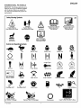
1
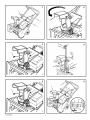
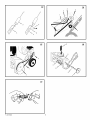
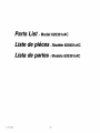
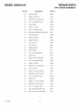
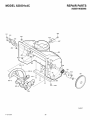
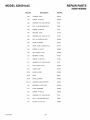
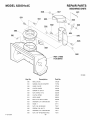
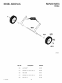
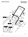
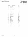
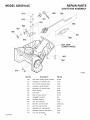
InstructionBook
Manueld'instructions
Manualde instrucciones
Snow Thrower
Model 620301x4C
chasse-neige
module 620301x4C
Quitanieves
modelo 620301x4C
Read and keep this book for future reference. This book contains important information on SAFETY,
ASSEMBLY,OPERATION,AND MAINTENANCE.
Lisez et conservez ce manuel pour r_f_rence. Ce manuel contient des informations importantes
concernant la SECURITE, LE MONTAGE, L'UTILISATIONET L'ENTRETIEN.
Lea y conserve este manual para referenciasfuturas. Este manual contiene informaci6n importante
sobre SEGURIDAD, ENSAMBLAJE, FUNCIONAMIENTO Y MANTENIMIENTO.
F-OO1133M
NOTE: This unit is equipped with an internal combustion engine
and must not be used on or near any unimproved
forest-covered, brush-covered or grass-covered land unless
the engine's exhaust system is equipped with a spark arrester
meeting applicable local or state laws (if any). If a spark arrester
is used, it must be maintained in effective working order by the
operator,
Engine Exhaust, some of its constituents,
and
certain vehicle components
contain or emit
chemicals
known to the State of California to
cause cancer and birth defects or other reproductive harm.
In the State of California, the above is required by law (Section
4442 of the California Public Resources Code), Other states
may have similar laws, Federal laws apply on federal lands. See
an Authorized Service Center for a spark arrester for the
muffler.
Battery posts, terminals
and related accessories contain lead and lead compounds,
chemicals known to the State of California to cause
cancer and birth defects or other reproductive
harm. WASH HANDS AFTER HANDLING.
REMARQUE : cette machine est 6quipee d'un moteur
combustion interne et ne dolt pas etre utilisee sur un terrain
forestier, buissonnant ou herbeux non prepare, a moins que le
dispositif d'echappement soit pourvu d'un pare-etincelles
conforme a la legislation locale ou de 1'etat (le cas 6cheant). Si
un pare-etincelles est utilise, celui-ci dolt etre maintenu en
parfait etat de fonctionnement par I'utilisateur.
Les gaz d'_chappement
du moteur, certains
dl_ments
de leur composition,
ainsi
que
certains organes du vdhicule
contiennent
ou
dmettent
des substances chimiques qui, selon
i'Etat de Californie,
peuvent causer le cancer,
des
malformations
a
la naissance,
ou
repr_sentent
un danger pour la reproduction.
Au sein de I'etat de Californie, la ]oi exige la prise en compte
des precautions mentionnees ci_:lessus (clause 4442 du
California Public Resources Code). D'autres 6tats peuvent
presenter des lois similaires. Les lois federales s'appliquent sur
les terres federales. S'adresser 9 un centre de maintenance
agree pour I'achat d'un pare-etincelles pour I'echappement.
Les bornes
et peles
de batterie
et autres
accessoires
de ce type contiennent du plomb et
des
compos_s
de
plomb,
substances
chimiques
qui, selon
rEtat
de Californie,
peuvent causer ie cancer, des malformations
ia naissance, ou repr_sentent un danger pour ia
reproduction.
NOTA: Esta unidad est9 equipada con un motor de combustien
intern& per Io que no debe usarse sabre o cerca de terreno
baldio, arbolado, herboso o de matorral a menos que el sistema
de escape del motor dispone de un parachispas que cumpla
con las leyes locales o estatales pertinentes (si las hay). Si hay
un parachispas instalado en el motor, el usuario debe
mantenerlo en buenas condiciones de operacien.
€:ste es un requisito legal para el estado de California (Seccien
4442 del Cedigo de Recursos P_blicos de California), Puede
que arras estados tengan leyes similares, En los terrenos
federales se aplican las leyes Federales. Visite un Centre de
servicio autorizado si desea instalar un parachispas para el
sistema de escape.
Fq)O1133M
Las emanaciones
de escape producidas
por
este motor contienen
quimicos
reconocidos
por el Estado de California como carcinbgenos,
tambien pueden producir defectos en los reci6n
nacidos
o causar
otros dahos
al sistema
reproductivo.
Los bornes, terminales y accesorios
relacionados con ia bateria contienen plomo y compuestos del plomo, ademas de sustancias quimicas
que el Estado de California reconoce como carcinbgenas,
ademds estas sustancias
pueden
producir da_os congenitos a los bebds y da_os
al sistema reproductor
humano. DEBE LAVARSE MUY BIEN LAS MANOS DESPUES DE MANiPULAR ESTOS COMPONENTES.
2
_2
5
4
3
4
7
5
/
5
/
F_O1133M
14
3
Z
2
,/
8_
2
2
f
3
1
\
1
1
1
2J%
11
12
2
4
}
5
Fq)O1133M
4
13
14
3
2
1
5
)111111_
6
4
15
3
4
5
1
17
Fq)O1133M
5
ENGLISH
CONTENTS
PRODUCT INFORMATION
OWNER'S INFORMATION
INTERNATIONAL PICTORIALS
ASSEMBLY
OPERATION
MAINTENANCE
MAINTENANCE CHART
TROUBLE SHOOTING CHART
6
6
7
9
10
12
12
14
TWO YEAR LIMITED WARRANTY
Murray, Inc. warrants to the original purchaser
that this unit shall be free from defects in
material and workmanship under normal use
and service for a pedod of Two (2) Year from
the date of purchase; however, this warranty
does not cover engines, accessories (such as
electdc starters) and Normal Wear Parts (except
as noted below) as the companies that
manufacture these items furnish their own
warranties and provide service through their
authorized field service facilities. For additional
information, see the warranties covering these
particular parts. If you are uncertain whether
PRODUCT
INFORMATION
The owner must be certain that all the product
information is included with the unit. This
information includes the INSTRUCTION
BOOKS, the REPLACEMENT PARTS and the
WARRANTIES. This information must be
included to make sure state laws and other laws
are followed.
OWNER'S
INFORMATION
This instruction book is written for a person with
some mechanical ability. Like most service
books, not all the steps are described. Steps on
how to loosen or tighten fasteners are steps
anyone can follow with some mechanical ability.
Read and follow these instructions before you
use the unit.
Know your product: If you understand the unit
and how the unit operates, you will get the best
performance. As you read this manual, compare
the iIIustrations to the unit. Learn the location
and the function of the controls. To help prevent
an accident, follow the operating instructions
Fq)O1133M
your unit contains or is equipped with one or
more of these pads, consult your dealer prior to
purchase. Subject to the terms and conditions
noted in this Limited WarTanty, we shall, at our
option, repair or replace at no cost to the original
purchaser any part covered by this Limited
Warranty during the applicable warranty period.
Normal Wear Parts are defined as drive belts,
augers, shear pins, tires and headlights. These
parts are warranted to be free from defects in
material and workmanship as delivered with the
product. Any claim for repair or replacement of
Normal Wear Parts must be made within thirty
(30) days of the date of purchase. No claims
involving damage caused from material use,
abuse or misuse will be honored.
This Murray, inc. Two (2) Year Limited
Warranty is your exclusive remedy; however,
this warranty is void or does not apply to any
unit that has been tampered with, altered,
misused, abused or used for rental or other
commercial and/or professional
(non-homeowner)
uses. Your warranty does not
cover minor mechanical adjustments which are
not due to any defect in material or
workmanship. For assistance in making such
adjustments, consult your instruction Book.
To make a claim under this Murray, inc. Two (2)
Year Limited Warranty, return the unit (or if
authorized in advance, the defective part) along
with your proof of purchase to an Authorized
Service Center near you. To locate the nearest
Authorized Service Center, call the Central Parts
Distributor for your area shown in the list
provided with your unit or check the Yellow Page
listings in your local telephone directory. If you
return the entire unit, we will repair the unit. ffwe
authorize the return of the defective part only, we
will either replace or repair the part.This Murray,
Inc. Two (2) Year Limited Warranty gives you
specific legal rights, and you may also have
other rights which vary from state to state. This
Limited Warranty is given in lieu of all other
expressed and implied warranties
including
the implied warranty of merchantability
and
warranty of fitness for a particular purpose. If
you need additional information on this written
warranty or assistance in obtaining service,
write:
MURRAY, INC.
Outdoor Power Equipment
Customer Service Department
no. Box 268
Brentwood, Tennessee 37027
1-800-251-8007
and the safety rules. Keep this manual for future
reference.
2.
Follow all the assembly and preparation
instructions.
IMPORTANT: Many units are not assembled
and are sold in cartons. It is the responsibility of
the owner to make sure the assembly instructions in this manual are exactly followed. Other
units are purchased in an assembled condition.
On assembled units, it is the responsibility of the
owner to make sure the unit is correctly assembled. The owner must carefully check the
unit according to the instructions in this manual
before it is first used.
3.
Inspect the unit.
4.
Make sure that the operator of the unit
knows how to correctly use all standard
and accessory equipment.
5.
Operate the unit only with guards, shields,
and other safety items in place and working
correctly.
6.
Correctly
7.
Service the unit only with authorized or approved replacement pads.
8.
Complete
Environmental
WARNING: Look for this symbol to indicate
important safety precautions. This symbol
indicates: "Attention!
Become Alert! Your
Safety Is At Risk."
Responsibility
Of The Owner
The responsibility of the owner is to
follow the instructions below.
1.
Carefully read and foIIow the rules for safe
operation.
6
adjust the unit.
all maintenance
on the unit.
Awareness
•
Do not fill the engine's fuel tank completeIy
full.
•
Drain fuel for off-season
•
Use only unleaded gasoline.
•
Service the air cleaner regularly.
•
Tune-up
•
Keep equipment
condition.
•
Dispose of used engine oil properly.
storage.
the engine regularly.
in efficient operating
ENGLISH
INTERNATIONAL
PICTORIALS
IMPORTANT: The following
pictorials are located on your unit or on literature supplied
with the product. Before you operate the
unit, learn and understand the purpose for
each pictorial.
18
Safety Warning Symbols
DANGER
Thrown Objects.
Keep Bystanders Away,
DANGER
Thrown Objects.
Keep Bystanders Away.
WARNING
Hot Surface
Slow
DANGER
Stop The Engine
Before Unclogging
Discharge Chutet
)
Fast
_
Electric Start
I
0
WARNING
STOP
Control And 0perat_ols
Engine Start
I,I H
Engine Stop
On
Choke Off
Reverse
Throttle
Primer Button
Ignition Key
Electric Starter
Engage
Auger Clutch
Auger Collector
Drive Clutch
Fuel
Discharge
LEFT
Weight Transfer
Lift Handle To Engage
Fq)O1133M
Discharge
RIGHT
DANGER
Avoid Injury From
Rotating Augen Keep
Hands, Feet And
Clothing Awa_
IMPORTANT
Read Owner's Manual
Before Operating
This Machine.
Choke On
O
Weight Transfer
Depress Pedal To Disengage
Transmission
7
Engine Run
Engine Off
N
Neutral
Forward
Ignition Off
Ignition On
Discharge
Oil
DOWN
Discharge
UP
Fuel Oil Mixture
Ignition Key
Insert To Run, Pull Out To Stop.
ENGLISH
Safe Operation Practices for Snow Throwers
As Recommended
By: American National Standards Institute.
IMPORTANT: Safety standards require operator
presence controls to minimize the risk of injury.
Your snow thrower is equipped with such controls. Do not attempt to defeat the function of the
operator presence control under any circumstances.
Training
1.
2.
7.
Never attempt to make any adjustments
while the engine (motor) is running (except
when specifically recommended by manufacturer).
11. Do not clear snow across the face of slopes.
Exercise extreme caution when changing
direction on slopes. Do not attempt to dear
steep slopes.
8.
Let engine (motor) and snow thrower adjust
to outdoor temperatures before starting to
dear snow.
12. Never operate the snow thrower without
proper guards, plates or other safety protective devices in place.
9.
Always wear safety glasses or eye shields
dudng operation or while performing an adjustment or repair to protect eyes from foreign
objects that may be thrown from the snow
thrower'.
13. Never operate the snow thrower near enclosures, automobiles, window wells, drop-offs,
and the like without proper adjustment of the
snow discharge angle. Keep children and
pets away.
Read the operating and service instruction
manual carefully. Be thoroughly familiar with
the controls and the proper use of the equipment. Know how to stop the unit and disengage the controls quickly.
Never allow children to operate the equipment. Never alow adults to operate the
equipment without proper instruction.
3.
Keep the area of operation clear of alI persons, particularly smali chiIdren and pets.
4.
Exercise caution to avoid slipping or falling
especially when operating in reverse.
14. Do not overload the machine capacity by attempting to clear snow at too fast a rate.
Operation
1.
Thoroughly inspect the area where the equipment is to be used and remove all doormats,
sleds, boards, wires, and other foreign objects.
2.
Disengage all clutches before starting the engine (motor).
3.
Do not operate the equipment without wearing adequate winter outer garments. Wear
footwear that will improve footing on slippery
surfaces.
4.
Use an approved fuel container.
b.
Never remove fueI tank cap or add fuel to
a running engine (motor) or hot engine
(motor).
c.
Fill fuel tank outdoors with extreme care.
Never fill fuel tank indoors.
d.
Reptace fuel cap securely and wipe up
spilled fuel.
e.
Never store fuel or snow thrower with fuel
in the tank inside of a building where
fumes may reach an open flame or spark.
Check fuel supply before each use, allowing space for expansion as the heat of the
engine (motor) and/or sun can cause fuel
to expand.
5.
For all units with electric starting motors use
electric starting extension cords certified
CSA/UL Use only with a receptacle that has
been installed in accordance with local inspection authorities.
6.
Adjust the snow thrower height to dear gravel
or crushed rock surface.
Fq)O1133M
16. Never direct discharge at bystanders or aliow
anyone in front of the unit.
Do not use this machine if you are mentally
or physically unable to operate this machine
safely.
17. Disengage power to the collector/impeller
when snow thrower is transported or not in
use.
3.
Do not put hands or feet near or under rotating parts. Keep clear of the discharge opening at all times.
4.
Exercise extreme caution when operating on
or crossing gravel drives, walks or roads.
Stay alert for hidden hazards or traffic.
18. Use only attachments and accessories approved by the manufacturer of the snow
thrower (such as tire chains, electric start kits,
ect.).
19. Never operate the snow thrower without good
5.
6.
Handle fuel with care; it is highly flammable.
a.
15. Never operate the machine at high transport
speeds on slippery surfaces. Look behind
and use care when backing up.
2.
Preparation
1.
Do not operate this machine if you are taking
drugs or other medication which can cause
drowsiness or affect your ability to operate
this machine.
After striking a foreign object, stop the engine
(motor), remove the wire from the spark plug,
thoroughly inspect snow thrower for any
damage, and repair the damage before restarting and operating the snow thrower.
If the unit should start to vibrate abnormally,
stop the engine (motor) and check immediately for the cause. Vibration is generally a
warning of trouble.
7.
Stop the engine (motor) whenever you leave
the operating position, before unclogging the
auger/impeller housing or discharge chute
and when making any repairs, adjustments,
or inspections.
8.
When cleaning, repairing, or inspecting, make
certain the augedimpeIler and all moving
parts have stopped and all controls are disengaged. Disconnect the spark plug wire and
keep the wire away from the spark plug to
prevent accidental starting.
9.
Take all possible precautions when leaving
the snow thrower unattended. Disengage the
auger/impeller, stop engine (motor), and remove key.
10. Do not run the engine (motor) indoors, except
when starting the engine (motor) and for
transporting the snow thrower in or out of the
building. Open the outside doors; exhaust
fumes are dangerous (containing CARBON
MONOXIDE, an ODORLESS and DEADLY
GAS).
8
visibility or light. Always be sure of your footing and keep a firm hold on the handles.
Walk;never run.
20. Do not over-reach. Keep proper footing and
balance at all times.
21. Exercise caution if operating on steep sioping surfaces.
22. This snow thrower is for use on sidewalks,
driveways and other ground level surfaces.
23. Do not use the snow thrower on surfaces
above ground level such as roofs of residences, garages, porches or other such
structures or buiidings.
Maintenance
And Storage
1.
Check shear" bolts and other bolts at frequent
intervals for proper tightness to be sure the
equipment is in safe working condition.
2.
Never store the snow thrower with fuel in the
tank inside a building where ignition sources
are present such as hot water and space
heaters, clothes dryers, and the like. Allow
the engine (motor) to cool before storing in
any enclosure.
3.
Always refer to operator's guide instructions
for important details if the snow thrower is to
be stored for an extended period.
4.
Maintain or replace safety and instruction Iabels, as necessary.
5.
Run the snow thrower a few minutes after
throwing snow to prevent freeze-_p of the
auger/impelIer.
ENGLISH
ASSEMBLY
6. Turn the chute deflector (5) around toward
the front of the snow thrower.
Read and follow the assembly and adjustment
instructions for your snow thrower. All fasteners
are in the parts bag. Do not discard any parts or
material until the unit is assembled.
assembly
maintenance
to the
WARNING: orBefore
doing any
snow thrower, remove the wire
from the spark plug.
l_lL
NOTE: In this instruction
book, left and right
describe the location of a part from the operator's position behind the unit.
NOTE: Torque is measured in foot pounds
(metric N.m). This measurement describes
how tight a nut or bolt must be. The torque is
measured with a torque wrench.
NOTE: Illustrations
begin on page 3.
Tools Required
1
Knife
1
Pliers
How To Remove The Snow
From The Carton
Thrower
1. Locate all parts that are packed separately
and remove from the carton.
2.
Remove and discard the packing materiai
from around the snow thrower.
3. Cut down all four corners of the carton and
lay the side panels fiat.
4.
To Assemble
The Handle
1. Remove the packing material from the upper
and lower handles.
2. (Figure 1) Loosen the knobs (1) on each
side of the handle (2).
Raise the upper handle (2) to the operating
position.. Hold the upper handle (2) apart to
prevent scratching the lower handle.
NOTE: Make sure the cables are not
caught
dle.
between
the upper and lower han-
4. Tighten the knobs (f).
5. (Figure 2) Cut and discard the cable tie (3)
from the lower end of the chute control rod
(4).
The Lower
Chute
3)
For shipping purposes, some models are
shipped with the rear nut and bolt removed from
the lower chute (3). If the lower chute is not attached, assemble as follows.
FUEL MIXTURE CHART (mixture
I
U.S.
I
IMPERIAL
I
2. Tip the lower chute (3) backward until the
hole in the chute ring is aligned with the hole
in the lower chute (3).
3. Attach the lower chute (3) with bolt (f) and
nut (2). Make sure the nut (2) is tight.
St.(Metric
How
To Assemble
The Chute Control
Rod (Figure
4)
1. Remove the cotter pin (1), flat washer (2),
and wave washer (3) from the end of the
chute control rod (4). DO NOT DISCARD.
2. Mount the end of the chute control rod (4)
through the hoIe in the control rod bracket
(5). Make sure the worm gear (6) is aligned
with the notches (7) in the discharge chute
(8).
3.
Fasten the chute control rod (4) to the control rod bracket (5) with cotter pin (1), flat
washer (2), and wave washer (3).
4.
Rotate the chute control rod (4) clockwise
and counterclockwise.
Make sure the discharge chute (8) rotates freely.
How
_k
To Prepare
The Engine
ARNING:
Mix gasoline and oil as follows:
1. Pour one (1) U.S. quart of fresh, clean, unleaded automotive gasoline into a one gallon
size gasoline container.
2. Add 2.6 ounces of clean, high quality, twocycle oil to the gasoline container.
IMPORTANT: Do not use outboard motor
oil or multi-viscosity
oils,such as 10W-30
or 10W_,0.
3.
Install the fuel cap onto the gasoline container. Vigorously shake the gasoline container
to mix the oil with the gasoline.
4. Add an additional three (3) U.S. quarts of
gasoline to the gallon container. Again shake
the gasoline container.
Before
You Operate
Before you operate your new snow thrower,
please review the following checklist:
•
Make sure all assembly instructions
been completed.
have
•
Make sure the discharge
•
Make sure that no loose parts remain in the
carton.
Follow the engine
manufacturer's
for the
type of fuel and instructions
oil to use. Always
use a safety fuel container. Do not smoke
when adding the fuel mixture to the engine.
When inside an enclosure, do not fill the
fuel tank. Before you add the fuel mixture,
stop the engine. Let the engine cool for
several minutes.
See the engine manufacturer's instructions for
the type of fuel and oil to use. Before you use
the unit, read the information on safety, operation, maintenance, and storage.
How To Mix The Fuel Mixture
chute rotates freely.
As you ieam how to propedy use the snow
thrower, pay extra attention to the foilowing important items.
•
Make sure the fuel tank is filled with the
correct mixture o1 gasoline and oil.
•
Become familiar with the location of all
controls and understand their function.
•
Before starting the engine, make sure aii
controls operate correctly.
The two cycle engine, used on this snow threwer, requires a mixture of gasoline and oil for lu-
Do not fill the fuel tank with gasoline that does not have oil mixed in it. Shake the
gasoline container before each filling of the fuel tank.
Oll
(2.6 oz_.
1 U.S. Galton container
Fq)O1133M
50:1)
1. Use the bolt (1) and nut (2) found in the
parts bag to attach the lower chute (3).
DO NOT back over cables.
Remove the packing material from the handle assembly.
How
3.
(Figure
Hold onto the lower handle and pull the snow
thrower off the carton.
CAUTION:
5.
How To Assemble
brication of the bearings and other moving parts.
The correct fuel mixture ratio is 50:1 (2.6 oz. oil
per one gallon of gas - see the Fuel Mixture
Chart). Gasoline and oil must be pre-mixed in a
clean gasoline container'. Always use fresh,
clean, unleaded gasoline.
9
Shake Can
'_-
Add more gas
(3 U. S. Quarts)
I
ENGLISH
OPERATION
How To Start
NOTE: Illustrations
begin on page 3.
Know
Thrower
Your
Snow
(Figure
6)
Read this Instruction Book and safety rules before operation the snow thrower'. Compare the
illustration with your snow thrower to familiarize
yourself with the location of various controls and
adjustments.
snow
thrower
result inofforeign
,_
WARNING:
Thecan
operation
any
objects being thrown into the eyes,
which can result in severe eye damage.
Always wear safety glasses or eye shields
while operating the snow thrower. We recommend standard safety glasses or use a
wide vision safety mask over your glasses.
Chute Deflector (3) - Changes the distance the
snow is thrown.
Discharging
1. To stop discharging
drive lever (5).
Snow
snow, release the auger
2. To stop the engine, turn the ignition key (8)
to the off position.
Discharge Chute (4) - Changes the direction the
snow is thrown.
How
Auger Drive Lever (5) - Starts and stops the auger which propels the snow thrower.
2. To go forward, raise the handle (2) to allow
the rubber auger blades (f) to contact the
ground. Maintain a firm hold on the handle
(2) as the snow thrower starts to move forward. Guide the snow thrower by moving the
handle (2) either left or right. Do not attempt
to push the snow thrower.
Ignition Key (8) - Must be inserted and turned to
the on position to start the engine.
Primer Button (9) - Injects fuel directly into the
carburetor for fast starts in cold weather.
Electric Start Button (10)-On
els, used to start the engine.
electric start mod-
Switch Box (11) - On electric start models, used
to attach a 120 voit electric power cord.
Recoil Starter Handle (12) - Use to manually
start the engine.
Choke Control (14) - Use to start a cold engine.
Spark Plug Access Panel (15) - Remove to access the spark plug.
To Move
Forward
(Figure
8)
1. Hold the auger drive lever (5) against the
handle (2). The auger will begin rotating.
3. To stop, release the auger drive lever (5).
NOTE: If the auger continues to rotate, see
"How To Adjust The Auger Control Cable" in
the Service and Adjustments
section.
Before
Starting
The Engine
1. Before you service or start the engine, famiiiarize yourself with the snow thrower. Be
sure you understand the function and location of all controls.
2.
3.
Make sure that all fasteners are tight.
Make sure the fuel tank is filled with the cor-
4.
rect mixture of gasoline and oil
Become familiar with the location of all controis and understand their function.
5.
Before starting the engine, make sure all
controls operate correctly.
How To Control
The Discharge Of The Snow
Add The Fuel Mixture
charge
of snow
WARNING:
Nevertoward
direct bystanders.
the dis-
,_
before
unclogging
,_
WARNING:
Always the
stopdischarge
the engine
chute or the auger housing and before leaving the snow thrower.
1. (Figure 6) Turn the crank assembly (2) to
change the discharge direction of the snow.
2. (Figure 7) Loosen the wing knob (1) on the
chute deflector (2).
3.
Move the chute deflector (2) up for more
distance or down for less distance.
_k
ARNING:
Follow the engine
manufacturer's
instructions for the
type of fuel and oil to use. Always
use a safety fuel container. Do not smoke
when adding the fuel mixture to the engine.
When inside an enclosure, do not fill the
fuel tank. Before you add the fuel mixture,
stop the engine. Let the engine cool for
several minutes.
(Figure 8) Fill the fuel tank (3) to the full position with a fresh, clean fuel mixture. See "How
To Mix The Fuel Mixture" in the Assembty section.
4. Tighten the wing knob (1).
How To Stop The Engine (Figure 6)
How
To Throw
Snow
(Figure
6)
1. Engage the auger drive lever (5).
2. To stop throwing snow, release the auger
drive lever (5).
F_01133M
(Figure
6)
Models equipped with an Electric Starter
NOTE: An electric starter kit can be added to
recoil start engines. Electric starter kite are
available from your nearest authorized service center.
with a three-wire power cord and
ARNING: The starter is equipped
plug and is designed to operate on
120 volt A.C. household current. The power
cord must be properly grounded at all times
to avoid the possibility
of electrical shock
which can injure the operator. Carefully follow all instructions
in the "How To Start The
_1
How To Stop
(Figure 6)
Crank Assembly (2) - Changes the direction of
the discharge chute.
The Engine
To stop the engine, turn the ignition key (8) to
the off position. Keep the ignition key (8) in a
safe place. The engine will not start without the
ignition key (8).
10
Engine" section. Make sure that your house
wiring is a three-wire grounded system. If
you are not sure, ask a licensed electrician.
If your house wire system is not a
three-wire grounded system, do not use
this electric starter under any conditions. If
your system is grounded but a three-hole
grounded receptacle is not available to start
the engine, have a three-hole grounded receptacle installed by a licensed electrician.
To connect a 120 volt A.C. power cord, always connect the power cord to the switch
box (11) on the engine first. Then, plug the
other end into the three-hole grounded receptacle. When disconnecting the power
cord, always unplug the end from the
three-hole grounded receptacle first.
How To Start A Cold Engine (Figure 6)
1. FilI the fuel tank with a fresh, clean fuel misture. See "How To Mix The Fuel Mixture" in
the Assembly section.
2. Move the choke control to FULL position.
3. Make sure the auger drive lever (5) is in the
disengaged (released) position.
4. Insert the ignition key (8) and turn to the on
position.
5. Move the choke control (14) to the full
choke position.
6. (Electric Start) Connect the power cord to
the switch box (11) located on the engine.
7. (Electric Start) Plug the other end of the
power cord into a three-hole, grounded 120
VOLT, A.C. receptacle. (See the WARNING
in this section).
8. Push the primer button (9). Every time you
push the primer button (9), wait two seconds. For the number of times required to
push the primer button (9), see the engine
manufacturer's instructions.
9.
(Electric Start) Push on the electric start
button (10) until the engine starts. Do not
crank for more than 10 seconds at a time.
The electric starter is thermally protected. If
the electric starter overheates, it will automatically stop and can only be restarted
when it has cooied to a safe temperature. A
wait of about 5 to 10 minutes is required to
allow the electric starter to cool.
10. (Recoil Start) Rapidly pull the recoil starter
handle (12). Do not allow the recoil starter
handle (12) to snap back. Slowly return the
recoil starter handle (12).
11. If the engine does not start in 5 or 6 tries,
See the "Trouble Shooting Chart" Instructions.
12. (Electric Start) When the engine starts, release the electric start button (10) and
move the choke control (14) to 1/2 choke
position. When the engine runs smoothly,
move the choke control (14) to the off position.
ENGLISH
13.(Electric
Start) First disconnect the power
cord from the three-hole receptacle. Then,
disconnect the power cord from the switch
box (11).
NOTE: In temperatures
below 8°F, allow
the engine to warm up for several minutes
before blowing snow.
indoors or in enclosed, poorly venARNING: Never run the engine
tilated areas. Engine exhaust contains carbon monoxide, an odorless and
deadly gas. Keep hands, feet, hair and
loose clothing away from any moving parts
located on the engine or the snow thrower.
The temperature
of muffler and nearby
areas may exceed 150°F. Avoid these
areas.
1. With the engine running, quickly pull the recoil starter handle (12) three or four times
with a continuous full arm stroke. This will
produce a loud clattering sound that is not
harmful to the engine or starter.
2. Stop the engine. Wipe all snow and moisture
from the carburetor cover', control levers and
cables. Also move the choke control (14)
and recoil starter handle (12) several times.
m_l=
How To Start A Warm Engine (Figure
6)
If an engine has been running and is still warm,
leave the choke control (14) in the off position
and do not push the primer button (9). If the
engine fails to start, follow the instructions "How
To Start A Cold Engine".
NOTE: Do not use the primer
start a warm engine.
button (9) to
How To Start An Engine With A Frozen Electric
Starter (Figure 6)
How To Remove
The Auger
3.
4.
If the engine still fails to start, repeat the two previous steps until the engine starts. Then, continue with the directions "How To Start A Cold
Engine".
To help prevent the possible freeze-up of the
recoil starter and of the engine controls, proceed
as follows after each snow removal job.
Fq)01133M
Disconnect the spark plug wire.
Do not place your hands in the auger housing (4) orthe discharge chute (3). Use a
pry bar to remove any snow or debris.
Snow Throwing
Tips
1. This snow thrower will propel itself forward
when the handle is raised enough to cause
the auger blades to contact the ground. The
auger should stop when auger control bar is
released. If it does not stop, see "How To Adjust The Auger Control Cable" in the adjustment section.
below.
2. Quickly release the recoil starter handle
(12). Allow the recoil starter handle (12) to
snap back against the recoil starter.
From
6)
1. Release the auger drive lever (5).
2. Remove the ignition key (8).
2.
1. Pull out the recoil starter handle (12) as far
as possible.
or Debris
(Figure
move snow or debris that may be_k
ARNING: Do not attempt to recome lodged in auger housing
without taking the following
precautions.
If the electric starter is frozen and will not turn
the engine, follow the instructions
Snow
Housing
Most efficient snowthrowing
is accomplished
when the snow is removed immediately after
if falls.
3.
For complete snow removal, slightly overlap
each previous path.
4. Whenever possible, discharge the snow
down wind.
5. The distance the snow will be discharged
can be adjusted by moving the discharge
chute deflector. Raise the deflector for more
distance or lower the deflector for less distance.
6.
In windy conditions, lower thechute deflector
to direct the discharged snow close to the
ground where it is less likely to blow into unwanted areas.
11
7.
For safety and to prevent damage to the
snow thrower, keep the area to be cleated
free of stones, toys and other foreign objects.
8.
Do not use the auger propelling feature when
clearing gravel or crushed rock driveways.
Move the handle down to slightly raise the
auger.
9. The forward speed of the snow thrower is
dependent on the depth and weight of the
snow. Experience will establish the most effective method of using the snow thrower under different conditions.
10.After each snow throwing job, allow the engine to run for a few minutes. The snow and
accumulated ice will melt off the engine.
11. Clean the snow thrower after each use.
12. Remove ice, snow and debris from the entire
snow thrower. Flush with water to remove all
salt or other chemicals. Wipe snow thrower
dry.
Dry And Average
Snow
1. Snow up to eight inches deep can be removed rapidly and easily by walking at a
moderate rate. For snow or drifts of a greater
depth,slow your pace to allow the discharge
chute to dispose of the snow as rapidly as
the auger receives the snow.
2.
W_
Plan to have the snow discharged
rection the wind is blowing.
in the di-
Packed Snow
Move slowly into wet, packed snow. If the wet,
packed snow causes the auger to slow down or
the discharge chute begins to clog, back off and
begin a series of short back and forth jabs into
the snow. These short back and forth jabs, four
to six inches, will "belch" the snow from the
chute.
Snow Banks And Drifts
In snow of greater depth than the unit, use the
same "jabbing" technique described above. Turn
the discharge chute away from the snow bank.
More time will be requited to remove snow of
this type than level snow.
ENGLISH
MAINTENANCE
CUSTOMER
CHART
RESPONSIBILITIES
SERVICE
RECORDS
Fill in dates as you
complete regular
service.
Check And Tighten All Screws and Nuts
Before
Each
Use
'
N/
First
2
Hours
Every
5
Hours
•
Every
10
Hours
.
Every
25
Hours
Each
Season
.
Before
Storage
SERVICE DATES
..
Check Spark Plug
Check Fuel
Drain Fuel
.......
N/
Lubricate Chute Control Flange
MAINTENANCE
How To Adjust
NOTE: Illustrations
If the chute crank will not rotate fully to the left or"
right, adjust as folIows.
begin on page 3.
Use the following maintenance section to keep
your unit in good operating condition. All the
maintenance information for the engine is in the
engine manufacturer's instructions.
Before you
start the engine, read this book.
spection, adjustment
(except
WARNING: Before you make an incarburettor),
or repair, disconnect
the wire from the spark plug.
The Chute
How To Replace The Drive Belt
Crank
1. (Figure 11) Loosen nuts (1).
2.
Move the crank adjusting bracket (2) to
allow 1/8 inch (3ram) clearance (3) between
the notch in the flange (4) and the outer diameter of the worm gear (5).
3. Tighten the nuts (1).
The drive belt is of special construction and
must be replaced with odginaI factory replacement belt available from your nearest authorized
service center.
1.
2.
(Figure 14) Remove the drive belt (1) from
the idler pulley (2).
3.
Remove the drive belt (1) from the engine
pulley (3). Be careful, not to bend the belt
guides (4).
4.
(Figure 15) Remove the drive belt (1) from
the auger pulley (5).
5.
Remove the old drive belt (1).
,_
General Recommendations
The warranty on this snow thrower does not cover items that have been subjected to operator
abuse or negIigence. To receive full value from
the warranty, the operator must maintain the
snow thrower as instructed in this manual.
Some adjustments must be made periodically to
propedy maintain the snow thrower.
After
Each
Check for any loose or damaged parts.
•
Tighten any Ioose fasteners.
•
Check and maintain the auger.
•
Check controls to make sure they are
functioning
All adjustments in the Maintenance
section of
this manual should be checked at least once
each season.
How To Remove The Top Cover
(Figure 9)
1. Remove the five screws (1) from the top
cover (2).
2. Remove the top cover (2).
3. To install the top cover (4), reverse the
above steps.
Cable
2.
(Figure 13) Slide the cable boot (3) offthe
cable adjustment
bracket (4).
3.
Push the bottom of the auger control cable
(5) through the cable adjustment
bracket
(4) until the "Z" hook (6) can be removed.
Remove the "Z" hook (6) from the cable
adjustment
bracket (4). Move the "Z" hook
(6) down to the next adjustment hole.
5. Pull the auger control cable (5) up through
the cable adjustment
bracket (4).
(Figure 9)
1. Lubricate the clute control flange (7). Apply
a clinging type of grease such as Lubriplate.
Fq)O1133M
6. To install the new drive belt (f), reverse the
above steps.
7.
6.
Put the cable boot (3) over the cable adjustment
bracket (4).
7.
(Figure 12) Install the "Z" hook (1) to the
auger drive lever (2).
8. To check the adjustment, start the snow
thrower. Make sure the auger does not rotate
when the auger drive lever is released.
How To Remove
8.
NOTE: One screw (3) is shorter than the other screws• Make sure to install screw (3) in
the correct location•
12
Install belt cover. See "How To Remove The
Belt Cover".
How To Replace
The Auger
(Figure
16)
1. Remove the belt cover. See "How To Remove The Belt Cover".
2.
Remove the drive belt. See "How To Replace
The Drive Belt".
3.
Remove the auger pulley (1) from the auger
shaft (threads are left hand; turn clockwise to
remove).
The Belt Cover
(Figure 10)
1. The belt cover (1) is fastened with ten
screws (2). Remove all ten screws.
2. There are five screws on the front of the belt
cover (1). Three screws on the bottom of the
belt cover (1). Two screws on the top of the
belt cover (1).
Make sure the drive belt (1) is seated properly on the pulleys.
NOTE: When the auger control lever is
engaged, the belt guides (4) must be 1/16"
from the drive belt (1).
4.
3. Remove the belt cover (1).
4. To install the belt cover (1), reverse the
above steps.
Lubrication
Before Storage
Control
1. (Figure 12) Remove the "Z" hook (f) from
the auger drive lever (2).
properly.
If any parts are worn or damaged, replace
immediately.
The Auger
The auger control cable is adjusted at the factory. During normal use, the auger control cabie
can become stretched and the auger drive lever
wiII not properly engage or disengage the auger.
Use
•
•
How To Adjust
Remove the belt cover. See "How To Remove The Belt Cover".
4. To keep the auger (6) from rotating, set a
2"x4" piece of wood (2) on the center
paddle (3) to secure auger (6).
5.
Remove the fasteners from the bearing assembly (4). Remove the bearing assembly
(4) from the auger housing (5).
6.
Slide the auger (6) out of the bearing assembly on the right side of the snow thrower.
7. Tip the auger (6) enough to allow the auger
(6) to slide out of the auger housing (5).
8. To install auger (6), reverse the above steps.
ENGLISH
How
To Replace
The Spark
1. Drain the fuel tank.
Plug
NOTE: This spark ignition system meets all
requirements of the Canadian InterferenceCausing Equipment Regulations.
2.
3.
NOTE: This engine complies with all current
Australian and New Zealand limitations electromagnetic
interference.
The spark plug is housed in the engine compartment under the top cover and cannot be seen
under normal conditions.
1. Remove the top cover. See "How To Remove
The Top Cover".
2. The spark plug and wire are now visible.
3. Remove the spark piug wire.
4. Clean the area around the spark plug base to
prevent dirt from entering the engine when the
spark plug is removed.
5. Remove the spark plug.
6. Check the spark plug. If the spark plug is
cracked, fouIed or dirty, it must be replaced.
7. (Figure 17) Set the gap between the electrodes of the new spark plug at .030 inch. Next,
install the spark plug in the cylinder head and
firmIy tighten. Recommended torque is 18 to
20 foot pounds.
How To Prepare
Storage
The Snow
Thrower
For
while inside a building, near a fire,
ARNING: Do not remove gasoline
or while you smoke. Gasoline
fumes can cause an explosion or a fire.
_lk
Fq)O1133M
Let the engine run until it is out of gasoIine.
Remove the spark plug from the cylinder.
Pour one ounce of oil into the cylinder. Slowly pull the recoil-stad grip so that the oil will
protect the cylinder. Install a new spark plug
in the cylinder.
4. Thoroughly
5.
ciean the snow thrower.
Lubricate all lubrication
tenance section.
points. See the Main-
6.
Be sure that all nuts, bolts and screws are
secureiy fastened. Inspect all visible moving
parts for damage, breakage and wear. Replace if necessary.
7. Cover the bare metal parts ofthe blower
housing and auger with spray rust preventative lubricant.
8.
Put the unit in a building that has good ventilation.
9.
If the machine must be stored outdoors,
block up the snow thrower to be sure the entire machine is off the ground.
10. Cover the snow thrower with a suitable protective cover that does not retain moisture.
Do not use plastic.
How To Order Replacement
Parts
The replacement parts are shown either on the
back pages of this Instruction Book or in a
separate Parts List Book.
Use only manufacturer's authorized or approved
replacement pads. The letter placed on the end
of the part number denotes the type of finish for
13
the part, C for chrome, Z for zinc, a PAfor
purchased assembly, it is important that you
include this when ordering a part. Do not use
attachments or accessories not specifically
recommended for this unit. In order to obtain
proper replacement parts you must supply the
model number (see namepIate).
Replacement pads, except for the engine,
transmission, transaxle or differential, are
available from the store where the product was
purchased, a service shop recommended by the
store or from a "Murray, Inc. Central Parts
Distributor" listed on the back page of this
Instruction Book.
If you are unable to obtain parts or service in the
manner outlined above, then contact:
MURRAY, INC.
Outdoor Power Equipment
Customer Service Department
RO. Box 268
Brentwood, Tennessee 37027
1-800-251-8007
Collect telephone calls will not
be accepted.
Replacement parts for the engine, transaxle, or
transmission, are available from the
manufacturer's authorized service center found
in the yellow pages of the telephone directory.
Also, see the individual engine or transmission
warranties to order replacement pads.
When ordering the following information is
required:
(1) The Model Number
(2) Serial Number
(3) Part Number
(4) Quantity
ENGLISH
TROUBLE
SHOOTING
CHART
TROUBLE
CAUSE
CORRECTION
Difficult starting
Defective spark plug.
Replace spark plug.
Water or dirt in fuel system.
Use carburetor
fresh fuel.
Engine runs erratic
Blocked fuel line, empty gas tank, or stale
gasoline
Clean fuel line; check fuel supply; add fresh
gasoline
Engine stalls
Unit running on CHOKE.
Set choke lever to RUN position.
Engine runs erratic;
Loss of power
Water or dirt in fuel system.
Use carburetor
fresh fuel.
Excessive
Loose parts: damaged impeller
Stop engine immediately and disconnect spark
plug wire. Tighten all bolts and make all
necessary repairs. If vibration continues, have
the unit serviced by a competent repairman.
Drive belt loose or damaged.
Replace drive belt.
Auger drive belt loose or damaged.
Adjust auger drive belt; replace if damaged.
Auger control cable not adjusted correctly.
Adjust auger control cable.
Discharge chute clogged.
Stop engine immediately and disconnect spark
plug wire. Clean discharge chute and inside of
auger housing.
Foreign object lodged in auger
Stop engine immediately and disconnect spark
plug wire. Remove object from auger.
vibration
Unit fails to propel
itself
Unit fails to discharge
Fq)01133M
snow
14
bowl drain to flush and refill with
bowl drain to flush and refill with
PartsList- Model 620301x4C
Listedepi_ces-ModUle
620301x4C
Listadepartes- Modelo620301x4C
F_O1133M
33
MODEL 620301x4C
REPAIR PARTS
ENGINE ASSEMBLY
10
12
11
11
14
25
12
28
14
42
7O 71
40
72
73
47
75
33
45
41
342519E
Key No.
Description
No.
10
(SEE ENGINE MANUAL)
ENGINE
11
SCREW, 5/16-18
180077
12
WASHER
14
WASHER,
28
GUIDE, BELT
313440
28
SCREW
710312
33
SPRING, IDLER BRAKE
165x146
4O
ASSY, iDLER ARM
1501013
41
BOLT
333594
42
NUT, 5/16-18
71391
48
PULLEY, IDLER
48924
46
BOLT, CARRIAGE
45892
47
NUT
590
7O
PULLEY, ENGINE
338849
71
WASHER
25840
72
SCREW, 5/16-24X.75
181595
73
WASHER
120638
78
BELT
X.75
120638
71071
FLAT
OPERATOR'S
Fq)O1133M
Part
760928
MANUAL
34
Fq)O1133M
MODEL 620301x4C
REPAIR PARTS
FRAME COMPONENTS
ASSEMBLY
11
I
112
10
14
113
92
114
9O
92
91
342516
Key
Fq)01133M
Description
No.
Part
No.
8o
FRAME SIDE SUPPORT
RH
760272-853
81
FRAME SIDE SUPPORT
LH
760271-853
9o
ROD, SUPPORT
760169
01
WASHER,
71063
02
NUT, 3/8-16
lOO
BRACKET, GAS TANK
578093-583
lol
SCREW, 1/4-20X.75
180020
lO2
NUT, 1/4-20
782585
11o
TANK, FUEL
111
SCREW, 1/4-14X.88
112
CAP, GAS-RED
1257
113
TUBING 11.50 IN.
327290
114
CLAMP, FUEL LINE
HVSPTLK
71044
REGHEX
REGHEXCTRLK
55381
WAHHTAP
313681
48672
35
MODEL 620301x4C
REPAIR PARTS
TOP COVER ASSEMBLY
172
157
®
170
®
141
143
145
152
127
151
153-
313937
Fq)O1133M
36
MODEL 620301x4C
REPAIR PARTS
TOP COVER ASSEMBLY
Key
Fq)O1133M
Description
No.
Part
No.
12o
COVER, BOTTOM
121
SCREW, 1/4-20Xl
122
WASHER,
124
NUT, 1/4-20
126
COVER, CARB
326212
127
SCREW, 1/4-14X.75
313685
128
NUT, 1/4-10
578109
13o
GROMMET
131
KNOB, STAND TEE
333643
14o
SWITCH, IGNITION
56992
141
WSHER, REGINTLK
313683
142
NUT, 5/8-32 ACC
300193
143
2 KEYS & RING
49643
145
PRIMER, ENGINE
54601
146
HOSE, PRIMER
1259
147
NUT, 1/4-20
271172
18o
COVER, BELT
181
SCREW, 10-24X.50
182
NUT, #10-24
183
SCREW, 1/4-20X.50
313686
184
WASHER,
71067
185
NUT, 1/#-20 TINN
187
SCREW, 1/4-14X.75
188
WASHER,
189
NUT, 1/4-20
17o
COVER, TOP
171
SCREW, 1/4-14X.75
172
WASHER,
173
NUT, 1/4-10
174
SEAL, STRIP AUG HSING FOAM
55379
175
SEAL, STRIP CHUTE & GAS SEAL
55380
302265
.25
313674
FLAT .281X.63X.065
71067
REGHEXCTRLK
SPEED J TYPE
& WASHER,
ROPE GUIDE
REGHEXKEPS
782585
57587
57036
WAHHMA
REGHEXCTRLK
FLAT .281X.63X.065
12342
312300
578107
SLWATAP
FLAT .281X.63X.065
SPEED J TYPE
313685
71067
578109
331099
SLWATAP
FLAT .281X.63X.065
SPEED J TYPE
37
313685
71067
578109
MODEL 620301x4C
REPAIR PARTS
AUGER HOUSING
511
512
488
510
531
534
541
520-2
520-8
520
342517
F_O1133M
38
MODEL 620301x4C
REPAIR PARTS
AUGER HOUSING
Key
Fq)O1133M
Description
No.
Part
No.
48o
HOUSING, ASSY
330312
481
SCREW, 1/4-20X.75
302628
482
WASHER,
71067
483
NUT, 1/4-20
486
SCREW, 1/4-20X.63
11871
487
BRACKET, STOP
331126
488
WASHER,
331211
489
NUT, 1/4-20
490
BLADE, SCRAPER
334031
491
RIVET, OVSET .250DIAX.61LG
577707
492
SCREW, 1/4-20X.75
302628
493
NUT, CNTRLK 1/4-20
302635
51o
BEARING,
577023
511
SCREW, 1/4-20X1.00
710263
512
WASHER,
71067
513
NUT, CNTRLK 1/4-20
302635
52o
AUGER,
302783
FLAT .281X.63X.065
REGHEXCTRLK
FLAT .333X.87X.119
HEX NYLOCK
FLANGE
FLAT .281X.63X.065
ASSY
73826
780029
520-2
BLADE, AUGER
302565
520-6
RIVET
49838
520-8
BLADE, CENTER
335992
520-10
AUGER & BLADE SUPPORT
302552
530
BEARING & PLATE ASSY
583459
531
PLATE, RETAINER
334287
532
SCREW, 1/4-20X.63
579052
533
WASHER,
71067
534
NUT, 1/4-20
541
PULLEY V3L 6.00 O.D.
FLAT .281X.63X.065
REGHEXCTRLK
39
73826
338965
MODEL 620301x4C
REPAIR PARTS
DISCHARGECHUTE
591
\
\
591
\
/603
X
\
X
605
592
/
/
/
604
.......... 590
/
\
/606
\
\
592
JJ
......REF. ITEM
HOUSING
313939
Key
Fq)01133M
Description
No.
Part
No.
580
RING, CHUTE
314239
581
SCREW, #10X.50 HHTAPPST
711752
582
GUIDE, CHUTE
577021
590
CHUTE, LOWER
334234
591
SCREW 1/4-20X.50
313686
592
NUT, CNTRLK 1/4-2
302635
6o0
CHUTE, UPPER
325847
6Ol
WIRE, HINGE
308931
6o2
BOLT, 5/16-18X1.25
6o3
WASHER,
6o4
KNOB, T
6o5
NUT, 5/16-18
6o6
SCREW, 5/16-18X.75
578088
6o7
WASHER,
71071
6o8
NUT, 5/16-18
CARR.
FLAT .349X.69X.066
302843
71071
57171
REGHEX
FLAT .349X.69X.066
REGHEXCTRLK
4O
71037
71391
MODEL 620301x4C
REPAIR PARTS
WHEELS
650
651
660
661
334309
Key
Fq)O1133M
Description
No.
Part
No.
65o
AXLE SHAFT
313678
651
WASHER,
583409
66o
TIRE & RIM
760713
661
WASHER,
583409
662
RING, RET E
FLAT .391X1.OOX1.25
FLAT .391X1.OOX.125
577598
41
MODEL 620301x4C
REPAIR PARTS
HANDLE
ASSEMBLY
764
763
750
752
752
762
753
753
753
752
751
759
755
5HP OPTION
3HP OPTION
342532
Fq)O1133M
42
MODEL 620301x4C
REPAIR PARTS
HANDLE ASSEMBLY
Key
Fq)01133M
Description
No.
Part
No.
740
CABLE, UPPER
760774
741
BRACKET, CABLE ADJ
313441
742
CABLE, LOWER CONTROL
760773
743
BOOT, CLUTCH SPRING
308146
744
SPRING, EXTENSION
165x146
78o
HANDLE, LOWER
313487-853
781
SCREW, 1/4-20Xl
782
WASHER,
783
NUT, 1/4_20
782585
785
BRACKET, CABLE
761486-853
786
BOLT
712234
787
PULLEY
39298
789
NUT, 1/4_20
782585
760
UPPER HANDLE
313489-853
761
BAIL, CONTROL
313308-853
762
BOLT
337584
763
WASHER,
764
KNOB, T 3.00 WD
57171
765
NUT, 5/16-18
71037
313674
.25
71067
FLAT
311936
FORM
43
MODEL 620301x4C
REPAIR PARTS
CHUTE ROD ASSEMBLY
874_
860
...... _<_
853
851
\
i
as?
"857
855
870
REF. ITEM
LOWER HANDLE
/............ 863
864
313942
Key
F_O1133M
Description
No.
Part
No.
85o
ROD, ASSY UPPER CHUTE CONTROL
314996
851
WASHER,
71072
FLAT .406X.81X.066
852
PIN, COTTER .094 DIAX1.09LG
71082
853
WASHER,
CURVED SPRING
313431
855
WASHER,
FLAT .406X.81X.066
71072
856
KNOB, SLEEVE
57082
857
NUT, PUSH
331532
86o
BOLT, EYE 3/8-16X2.00
313712
861
GROMMET, EYE BOLT
148
863
WASHER,
71062
864
NUT, 3/8-16
87o
MDSPTLK
HEXJAM
71045
BRACKET, CHUTE ROTATE
333946-853
871
BOLT, 5/16-18X.75
340720
872
WASHER,
FLAT .349X.69X.066
71071
873
WASHER,
HVSPTLK
71060
874
NUT, 5/16-18
CARR.
.328X.60X.09
REGHEX
44
71037
Fq)O1133M
45
Fq)O1133M
46
F_O1133M
47
MURRAY,INC. CENTRALPARTSDISTRIBUTORS
DISTRIBUTEURSREGIONAUXDE PIECESMURRAY,INC.
DISTRIBUIDORESCENTRALESDE PIEZASDE MURRAY,INC.
BEBCO, INC.
CHILTONAIR COOLED ENGINE
GULF COAST ENGINE, INC.
22212nd.Ave. South
Birmingham,AL 35233
(205) 251-4600
1-800-828-8094
Alabama,Florida,Georgia,PuertoRico
319 4th. Ave.South
P.O.Box 150806
Nashville,TN. 37215
(615) 254-1637
1-800-621-6934
www.chiltoncom
panies.com
Arkansas (countiesClay,Craighead,
Crittendan,Cross,Greene,Jackson,
Lawrence,Lee,Mississippi,Monroe,Phillips,
Poinsett,Randolph,St. Francis,Woodruft),
Mississippi(countiesDesota,Panola,
Quitman,Tate,Tunica),Missouri(counties
Dunkin,New Madrid,Pemiscot),Tennessee,
Virginia (countiesBland,Buchanan,
Dickenson,Lee, Russell,Scott, Smyth,
Tazewell,Washington,Wise)
4202 RussellDr.
P.O.Box9724
CorpusChristi,TX. 78408
(316) 888-6999
1-800-825-6999
Arkansas(countiesHempstead,Howard,
Lafayette,LittleRiver,Miller,Nevada,Pike,
Sevier)NewMexico,Oklahoma, Texas,
Mexico
BILLIOU'S, INC.
1343SouthMainSt.
Porterville,CA. 93257
(559) 784-4102
1-877-245-5468
FAX 1-800-226-7337
Arizona,California, Hawaii,Nevada
BROWN & WISER, INC.
9991S.W.AveryStreet
P.O.Box 1109
Tualatin,OR. 97062
(503) 692-0330
1-800-882-4782
Alaska, Idaho (countiesAda,Adams,
Benewah,Boise,Bonnet,Boundry,Canyon,
Clearwater,Elmore,Gem, Idaho,Kooten,
Latah,Lewis,NezPerce,Owyee,Payette,
Ravalli,Shoshone,Valley,Washington),
Montana(countiesFlathead,Lake,Uncoln,
Mineral,Missoulo,Ravalli,Sanders),Oregon,
Washington
CPT CANADA POWER
TECHNOLOGY LIMITED
161WatlineAvenue
Mississauga,Ontario
L4Z-1P2
1-800-861-9559
(905) 890-6900
101-10411-178Street
Edmon_n, Alberta
T5S 1R5
(780)453-5791
1-800-861-9559
234 MigneronStreet
Ville St-Laurent,Quebec
H4T 1Y7
(514) 731-3559
1-800-861-9559
Canada
ENGINES SOUTHWEST
1255NorthHearne
Shreveport,LA. 71107
PO Box 67
Shreveport,LA. 71161
(318) 222-3871
1-800-388-6995
www.enginessw.com
Arkansas (exceptthese counties:Clay,
Craighead,Crittendan,Cross,Greene,
Hempstead,Howard,Jackson,Lafayette,
Lawrence,Lee,UttleRiver,Miller,Mississippi,
Monroe,Nevada,Phillips,Pike,Poinsett,
Randolph,Sevier,St. Francis,Woodruft)
Louisiana, Mississippi(exceptthese
counties:Desota,Panola,QuitmanTate,
Tunic&)
FRANK EDWARDS CO.
3626 ParkwayBlvd.
WestValley,UT 84120
(801) 736-8060
1-800-318-0201FAX
1-800-570-0491
Colorado, Idaho (countiesBannockBearlake,
Bingham,Blaine,Booneville,Butte,Camas,
Caribou,Cassia,Custer,Franklin,Fremont,
Gooding,Jefferson,Jerome,Lemhi,Uncoln,
Madison,Minidoka,Oneida,Power,Teton,
TwinFalls)Montana(all countiesexcept
Flathead,Lake,Lincoln,Mineral,Missoulo,
Ravalli,and Sanders),Utah,Wyoming
GARDNER, INC.
1150ChesapeakeAve.
Columbus,OH. 43212
(614)488-7951
1-800-848-8946
Indiana, Kentucky, Michigan(exceptupper
Peninsula),Ohio, WesternPennsylvania
with zip codesup to and including16999,
WestVirginia
F-OO1133M
48
OSCAR WILSON ENGINE & PARTS
826 LoneStarDr.
O'Fallon,MO. 63366
(314) 978-1313
1-800-873-6722
Illinois (S.of Hwy.80),Iowa, Kansas,
Missouri(all countiesexceptDunkin,
New Madrid,Pemiscet)Nebraska
R.B.I. CORPORATION
P.O.Box9318
Richmond,VA. 23227
(804) 550-2210
1-800-888-7149
FAX1-800-947-1335
Connecticut, Delaware,Districtof
Columbia,Maine,Maryland,Massachusetts,
NewHampshire,NewJersey,New York,N.
& S. Carolina,Pennsylvaniazips17000& up,
RhodeIsland,Vermont, Virginia(all counties
exceptBland,Buchanan,Dickenson,Lee,
Russell,Scott,Smyth,Tazewell,Washington,
Wise)
WISCONSIN MAGNETO
4727 N. TeutoniaAve.
P.O.Box9218
Milwaukee,Wt. 53209
(414) 445-2800
1-800-733-7388
Illinois (N. of Hwy.80),Michigan(upper
Peninsula),Wisconsin
800 McKinleySt.
Anoka,MN. 55303
(612) 323-7477
1-800-248-4016
Minnesota,North& SouthDakota