1
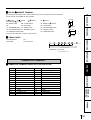
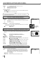
COLOUR VIDEO COPY PROCESSOR
MODEL
CP910E(ID)
OPERATION MANUAL
ALARM
SHEET
PAPER
S-VIDEO
THIS OPERATION MANUAL IS IMPORTANT
TO YOU.
PLEASE READ IT BEFORE USING YOUR
COLOUR VIDEO COPY PROCESSOR.
This video copy processor complies with the requirements of the EC Directive
89/336/EEC, 73/23/EEC and 93/68/EEC.
The electro-magnetic susceptibility has been chosen at a level that gains proper
operation in residential areas, on business and light industrial premises and on
small-scale enterprises, inside as well as outside of the buildings. All places of
operation are characterised by their connection to the public low voltage power
supply system.
INFORMATION
This Class A digital apparatus complies with Canadian ICES-003.
Cet appareil numérique de la classe A est conforme à la norme NMB-003 du Canada.
WARNING :
TO PREVENT FIRE OR SHOCK HAZARD, DO NOT EXPOSE THIS APPLIANCE TO
RAIN OR MOISTURE.
WARNING:
Use the AC power cord according to the recommendations as below so as not to interfere
with radio and television reception.
If you use other cables, it may cause interference with radio and television reception.
Case 1. Connect to the 120V receptacle of the room or the host equipment, in order to comply
with UL1950 and CAN/CSA C22.2 No. 950.
The AC power cord should be UL and CSA approved and consist of type SVT, size
18AWG, shielded, length 1.8m or shorter cord with IEC320/C13 type, 125V 10A or
higher rating connector and NEMA 5-15 type, 125V 10A or higher rating.
Case 2. Connect to the 230V receptacle of the room or the host equipment, in order to comply
with EN60950.
Use the included AC power cord.
CAUTION
RISK OF ELECTRIC SHOCK
DO NOT OPEN
CAUTION: TO REDUCE THE RISK OF ELECTRIC SHOCK,
DO NOT REMOVE COVER (OR BACK)
NO USER-SERVICEABLE PARTS INSIDE
REFER SERVICING TO QUALIFIED SERVICE PERSONNEL.
The lightning flash with arrowhead symbol, within an
equilateral triangle, is intended to alert the user to the
presence of uninsulated "dangerous voltage" within the
product's enclosure that may be of sufficient magnitude to
constitute the risk of electric shock.
The exclamation point within an equilateral triangle is
intended to alert the user to the presence of important
operating and maintenance (servicing) instructions in the
literature accompanying the appliance.
NOTE:
This equipment has been tested and found to comply with the limits for a Class A digital
device, pursuant to Part 15 of the FCC Rules. These limits are designed to provide reasonable
protection against harmful interference when the equipment is operated in a commercial
environment. This equipment generates, uses, and can radiate radio frequency energy and,
if not installed and used in accordance with the instruction manual, may cause harmful
interference to radio communications. Operation of this equipment in a residential area is
likely to cause harmful interference in which case the user will be required to correct the
interference at his or her own expense.
CONTENTS
1
2-4
5
6
7-9
PRECAUTIONS
Contents ................................................................................................
Safety precautions ................................................................................
Special features ....................................................................................
Unpacking .............................................................................................
Features and functions .........................................................................
Front panel ............................................................................................. 7
Rear panel ............................................................................................. 8
Remote control unit ................................................................................ 9
Connections .......................................................................................... 10
FEATURES
Connection with monitor and camera .................................................... 10
Before operation .................................................................................... 11-14
Paper sheet set ......................................................................................
Unlock the printing unit ..........................................................................
Installation of print paper ........................................................................
Installation of ink sheet ..........................................................................
Usage and keeping of paper sheet set ..................................................
11
11
11-12
12-14
14
Before printing ........................................................................................
Printing ...................................................................................................
Display on the monitor screen ............................................................
Memorizing and printing an image ......................................................
Selecting memorized image to print ....................................................
Image size and layout of memory pages ............................................
Multiple copy or continuous printing ....................................................
CONNECTIONS PREPARATION
Printing (Basic) ...................................................................................... 15-18
15
16-18
16
16
17
17
18
Printing (Special) ................................................................................... 19-21
Multi print ...............................................................................................
Separate print ........................................................................................
External remote terminal 1 .....................................................................
External remote terminal 2 .....................................................................
Camera-IN terminal ................................................................................
19
19
20
20-21
21
Setting the functions (Menu chart) ........................................................ 22-23
Monitor display chart .............................................................................. 22-23
24
24-25
26
26
27
27
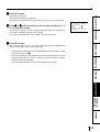
ADJUSTMENTS
MAIN MENU items .................................................................................
Operating MAIN MENU ..........................................................................
COLOR ADJ (Color adjustment) ............................................................
LAYOUT (Layout setting) .......................................................................
PRINT (Print setting) ..............................................................................
MEMORY POSITION (Position setting) .................................................
PRINTING
Adjustments & settings (MAIN MENU) .................................................. 24-27
Adjustments & settings (SERVICE MENU) ........................................... 28-33
Error messages .....................................................................................
Before calling for service .......................................................................
Overcoming paper jams ........................................................................
Cleaning ................................................................................................
Spec & options ......................................................................................
34
35-36
37
38
39
OTHERS
28
28
29
29-30
30
30
30-31
31
31-32
32
32-33
33
TROUBLESHOOTING
SERVICE MENU items ..........................................................................
Operating SERVICE MENU ...................................................................
SYSTEM SETUP (System setting) ........................................................
GAMMA ADJ (Gamma level setting) ......................................................
LAYOUT2 (Layout setting 2) ..................................................................
ANALOG COLOR ADJ (Analog image adjustment) ...............................
INPUT (Input signal setting) ...................................................................
OUTPUT (Output signal setting) ............................................................
KEY SET (Button function setting) .........................................................
RS232C SET (RS-232C setting) ............................................................
REMOTE SET (Remote signal setting) ..................................................
PREVIOUS ERROR(Error display) ........................................................
1
SAFETY PRECAUTIONS
In the interest of safety, please observe the following precautions:
POWER REQUIREMENT
This Colour Video Copy Processor is designed to operate on 100V-120V AC 50/60Hz in U.S.A. and Canada, 220V-240V AC 50/
60Hz in Europe. Never connect to any outlet or power supply having a different voltage or frequency.
WARNING: THIS APPARATUS MUST BE EARTHED.
AVERTISSEMENT: CET APPAREIL DOIT ETRE MIS A LA TERRE.
PROTECTIVE MEASURES
IF ABNORMALITIES ARISE, ....
Use of the unit during emission of smoke or abnormal sounds (without adopting countermeasures) is dangerous. In such a
case, unplug the power cord from the source outlet immediately, and request maintenance service from the sales dealer.
NEVER INSERT ANY OBJECT INTO THE UNIT
Foreign objects of any kind inserted into this unit constitute a safety hazard and can cause extensive damage.
DO NOT PLACE ANYTHING ON THE COLOUR VIDEO COPY PROCESSOR
Heavy objects placed on the Colour Video Copy Processor can cause damage or obstruct proper ventilation.
PROTECT THE POWER CORD
Damage to the power cord may cause fire or shock hazard. When unplugging, hold by the plug only and remove carefully.
DO NOT PLACE WATER CONTAINERS ON THE UNIT
Do not place flower vases, and other water-holding containers on the device. If, for some reason, water seeps to the inside of
the unit, unplug the power cord from the source outlet, and contact the sales dealer. If used without corrective measures, the
unit may be damaged.
“In the interest of safety, avoid handling of liquids near the unit.”
DO NOT REMOVE THE CABINET
Touching internal parts is dangerous, besides, it may lead to malfunction. Contact the sales dealer to carry out internal checks
and adjustments. Before opening the cover for eliminating a jammed paper, etc., be sure to disconnect the power cord plug.
UNPLUG THE POWER CORD DURING A LONG ABSENCE
Turn off the MAIN power switch and unplug the power cord during a long absence.
WHEN TRANSPORTING THE UNIT
When transporting the unit, remove the ink cassette and paper. Make sure to slide the printing unit lock switch to the lock
position.
BE CAREFUL AROUND PRINT PAPER EXIT SLOT
Do not insert your hand or any material into the paper exit slot during printing.
Do not touch the cutter blade inside the paper exit slot.
Otherwise, your finger will be injured.
DO NOT TOUCH THE THERMAL HEAD
Do not touch your hand to the thermal head (located inside the unit).
The thermal head is heated to high temperature.
This may cause injury.
BE CAREFUL WITH THE PRINTING UNIT
Do not move the unit while the printing unit is sliding out. This may cause injury.
Be careful not to catch your finger in the printing unit while the printing unit is being retracted into the unit.
CONNECTION CABLES
Use the provided power cord.
2
INSTALLATION LOCATIONS
PRECAUTIONS
MAINTAIN GOOD VENTILATION
Ventilation slots and holes are provided on the sides of this unit. Place the unit on a hard and level surface and locate at least 4
inches (10cm) from walls to insure proper ventilation. When putting the unit on the system rack, take a space between the unit
and the back of the rack.
UNSUITABLE LOCATIONS
Avoid shaky places or hot-springs areas where hydrogen sulfide and acidic ions are likely to be generated.
FEATURES
PLACES WITH HIGH HUMIDITY AND DUST
Do not place the unit locations with high humidity and dust. They can cause extensive damage. Avoid places where unit is
likely to be exposed to oily fumes and vapors.
PLACES NOT LIKELY TO BE EXTREMELY HOT
CONNECTIONS PREPARATION
Places exposed to direct sunlight, or near heating appliances can attain extremely high temperatures, which may deform the
cabinet, or can become a prime cause of damage.
PLACE THE UNIT ON A HORIZONTAL LEVEL
The unit is likely to be affected if it is placed in slanted conditions or in unstable places.
PROTECT AGAINST DEW FORMATION
In extremely cold regions, if the unit is moved quickly from an extremely cold place to warmer one, dew is likely to be formed.
If dew is formed, printing is not possible.
OPERATING AMBIENT TEMPERATURE RANGE
The operating ambient temperature range is 41°F - 104°F (5°C to 40°C), and humidity of 20% - 80%. When using the unit on
the system rack, be sure to keep this ambient temperature inside the rack.
FOR LONG OPERATING LIFE
Coat flaking and deformation are likely to occur if the unit is wiped with chemical dusters, benzine, thinner or any other solvent, if
rubber or PVC items are left in contact with the unit for extended duration, or if the unit is sprayed with insecticide.
PRINTING
UNSUITABLE MATERIALS FOR THE COLOUR VIDEO COPY PROCESSOR
CARE OF THE CABINET
ADJUSTMENTS
Unplug and clean with a soft cloth slightly moistened with a mild soap and water solution. Allow to dry completely before
operating. Never use petroleum base solutions or abrasive cleaners.
HEAD ABRASION
The thermal head, like the video head, wears out. When it is abraded, it becomes hard to print out fine details of the picture. In
such a case, it is necessary to replace the thermal head. Consult with the sales dealer for replacing the head.
TROUBLESHOOTING
CONNECTING DEVICES
Read thoroughly “Operating Precautions” of the instruction booklets for the devices connected with the Colour Video Copy
Processor.
The power cord must be disconnected after printing is over.
CAUTION ON RELOCATING
When transporting this unit, make sure it is not likely to be subjected to impacts. They can be a prime cause for damage.
Further, make sure to disconnect the power cord from the power outlet, and the cables from the connected devices.
OTHERS
3
SAFETY PRECAUTIONS
OTHER CAUTIONS
Dust or other foreign matter adhering to the print paper or the ink cassette, or deformation resulting from exposure to extremely low or high
temperatures could cause loss of colour, uneven colour or lines, or wrinkles in the print images.
NOTE:
YOUR UNDERSTANDING IS REQUESTED FOR THE LOSS OF IMAGES IN MEMORY DUE TO THE SUDDEN
OCCURRENCE OF A MALFUNCTION.
4
SPECIAL FEATURES
SPECIAL FEATURES
PRECAUTIONS
2 PRINT SIZES ARE AVAILABLE ACCORDING TO THE PURPOSE
2 printing sizes, L size (max.110 x 160 mm) and S size (max.110 x 105 mm), are selectable.
HIGH SPEED PRINTING
Printing speed is approx. 44 seconds (in S size print). Using a rollpaper shortens the time for installing and removing.
LARGE CAPACITY OF PRINTING
POSSIBLE OF A6 SIZE PRINTING IN HIGH QUALITY
High quality print is available in sublimation dye thermal method which is superior in repeatability of images. It also employs 256
gradients and about 16,700,000 colors in each YMC. A6 size printing helps its uses widely.
CONNECTIONS PREPARATION
MULTI PRINT FOR VARIOUS DEMANDINGS
2, 4, 6 and 16 images of multi print are available. Several multi print modes are selectable according to demanding.
UNIQUE COLOR IMAGE CONTROL SYSTEM WITH THE IC CHIP BUILT IN INK SHEET ROLLS
By setting the supplied IC chip to ink cassette, the remaining of ink sheet can be displayed. It also controls the colors of the
printing images.
SUITABLE FOR PHOTO SYSTEM
(1)
(2)
(3)
FEATURES
Maximum number of printing (S size) is 130 printings per a roll paper. The large capacity of rollpaper printing reduces a time of
exchanges.
Input and output control signals from CAMERA-IN/Rear remote interfaces
Image adjusting function such as contrast, brightness, depth etc. of printing image
Capable of storing 3 kinds of setting and adjustment according to each using condition.
PRINTING
ADJUSTMENTS
TROUBLESHOOTING
OTHERS
5
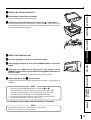
UNPACKING
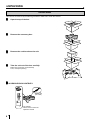
UNPACKING
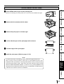
Take the unit out of the box by the following procedures. Make sure to check the contents.
Open the top of the box.
2
Remove the accessory box.
3
Remove the cushion above the unit.
R
EO O
ID SS
R V CE
LO PRO
CO PY
CO
1
R
EO O
ID S S
R V CE
LO PRO
C O PY
CO
4
Take the unit out of the box carefully.
Make sure to keep the unit horizontally.
Then, unwrap the packing.
2 ACCESSORY BOX CONTENTS
DISPLAY
COLOR
ADJUST
PROG.
FIELD
/FRAME
PRINT
Q' ty
MENU
SET
CLEAR
STOP
MEMORY
PAGE
MONITOR
MEMORY
Power cord
(CE cable)
PRINT
COLOUR VIDEO
COPY PROCESSOR
Ink cassette
Wired remote control unit
Operation manual
6
FEATURES & FUNCTIONS
PRECAUTIONS
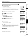
FRONT PANEL
1 2345 6 78 9 A B
ALARM
SHEET
PAPER
S-VIDEO
1 POWER BUTTON (INDICATOR)
Press to turn on power. Press again to turn off power.
When the power is turned on, the indicator illuminates.
2 ALARM INDICATOR
When this unit is overheated, this indicator goes on and
off. When other error occurs, it lights up.
3 SHEET ERROR INDICATOR
When an error concerning ink sheet occurs, this indicator
lights up.
4 PAPER ERROR INDICATOR
Press to print the image memorized by the MEMORY
button. The image on the monitor screen switches to the
picture of the input signal.
8
6
Press to decrease the value of each setting item. To set
the value, select SET with
MENU button and press
PLUS (+) button.
D OPEN BUTTON
Press to slide out the printing mechanism. Open the
mechanism to load paper and ink cassette or to clear a
paper jam.
E TRAY
Holds the printed paper which was come out from the print
outlet. Press down the knob to pull out the tray. Make sure
to pull it out before using this unit.
F REMOTE TERMINAL
G PRINTING UNIT LOCK SWITCH
Connects the remote control unit supplied.
Locks the printing unit.
Shift the switch to the left (LOCK side) to lock and to the
right (UNLOCK side) to unlock.
This unit is locked when shipping. When transporting this
unit, make sure to lock the unit.
7
OTHERS
Press to increase the value of each setting item. To set
the value, select SET with
MENU button and press this
button.
The printed paper comes out here.
Do not put any objects in front of the outlet.
TROUBLESHOOTING
Press for color adjustment. The item will be switched in
order of;
SELECT COLOR/B&W →BRT → CONT → R-SUB → G-SUB
→ B-SUB→ CENTER → CANCEL → SET → SELECT
COLOR/B&W. (When selecting B&W, R-SUB, G-SUB, B-SUB
change to Y-SUB, M-SUB, C-SUB.)
To go back to the normal screen, press PLUS (+) button
while CANCEL or SET is selected.
See page 26.
ADJUSTMENTS
C PRINT OUTLET
This lamp always lights up.
6
A MEMORY BUTTON
B PRINT BUTTON
PRINTING
5 INPUT SIGNAL INDICATOR
6 MENU BUTTON
8 PLUS (+) BUTTON
Switches the display on the monitor. When this button is
pressed, the picture on the monitor screen switches
between the picture of the input signal (source image) and
the memorized image.
When pressing MEMORY button while holding this button,
print paper will be fed and cut automatically, and the
mechanism will be initialized. Make sure to press
MONITOR button first, or a new image will be memorized.
Press to memorize the image to be printed.
When an error concerning print paper occurs, this indicator
lights up.
8
9 MONITOR BUTTON
CONNECTIONS PREPARATION
C
D
E
F
7 MINUS (-) BUTTON
FEATURES
G
FEATURES & FUNCTIONS
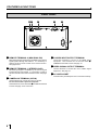
REAR PANEL
12 3
4
5
CAMERA-IN
REMOTE
S-VIDEO/IN S-VIDEO/OUT
VIDEO OUT
AC IN
6
1 REMOTE TERMINAL 2 (MINI DIN 8 PIN)
4 S-VIDEO INPUT/OUTPUT TERMINAL
2 REMOTE TERMINAL 1 (STEREO JACK)
5 VIDEO SIGNAL OUTPUT TERMINAL
Memorizing images and printing is available by the remote
signal inputted through this terminal. It is necessary to
make a circuit for remote control unit to use the function.
See pages 20-21.
Memorizing images is available by the remote signal
inputted through this terminal. It is necessary to make a
circuit for remote control unit to use the function. See page
20.
3 CAMERA-IN TERMINAL (25 PIN)
Use this terminal to connect this unit to a camera.
Do not connect with a personal computer.
This terminal can not be used when S-VIDEO IN terminal
is used. See page 10 for connection.
4
8
3
Use these terminals to connect to S-VIDEO signal
equipment. This terminal can not be used when
CAMERA-IN terminal is used. See page 10.
Use this terminal to connect this unit to VIDEO signal
equipment. See page 10.
6 AC LINE SOCKET
Connects to the provided power cord. Insert the cord firmly.
5 SET BUTTON
12
DISPLAY
COLOR
ADJUST
PROG.
FIELD
/FRAME
PRINT
Q' ty
MENU
SET
STOP
MEMORY
PAGE
MONITOR
MEMORY
PRINT
Press to cancel the printing process and start mechanical
initializing. When pressing these buttons during displaying
the main menu, the service menu will be displayed. When
pressing these buttons during stand-by status, the print
quantity is set to 1.
7 MEMORY PAGE BUTTON
Use to select the image memorized . The memory page is
switched every time this button is pressed. The selected
memory page mark illuminates.
8 PRINT BUTTON
Press to print the image memorized with the MEMORY
button.
9 PROGRAM BUTTON
Press the PROG. button to select between 3 types of user
presets. Functions previously set with the MENU can be
stored into one of 3 memories and recalled. Programs
cannot be changed during printing. The selected program
number is displayed for 3 seconds after pressing this
button. It may take longer to change the program.
A {, }, [, ] BUTTONS
Press to switch black and white / color print.
Use to set the MENU display. Values are increased/
decreased and the cursor position is changed with these
four buttons. See page 24 and 28.
2 FIELD/FRAME BUTTON (LINE ON/OFF)
3 DISPLAY BUTTON
Press to display the set condition on the monitor screen.
Press again to switch off the display.
{
Use to set the number of copies to be printed. Press
to
increase the number and
to decrease the number. The
set number of copies is displayed on the monitor screen
for 3 seconds after pressing these buttons. See page 18.
When pressing
or
button during printing, the counter
becomes “1” and continuous printing is cancelled.
}
{ }
Press to display MAIN MENU used for various settings.
See pages 22-23.
C CLEAR BUTTONS
Press to eliminate all or a part of memorized images.
D MONITOR BUTTON
Press to switch the image of the input signal and the
memorized image being displayed.
E MEMORY BUTTON
Use to memorize the image to be printed. The memorized
image is displayed on the monitor screen, and then the
image of the input signal is displayed.
TROUBLESHOOTING
4 PRINT QUANTITY {, } BUTTONS
B MENU BUTTON
ADJUSTMENTS
Press to switch on/off of the frame showing the print area
on the display. This button is available when LINE of
MEMORY POSITION menu in MAIN MENU is set to ON.
PRINTING
1 COLOR ADJUST BUTTON
CONNECTIONS PREPARATION
CLEAR
6 STOP BUTTONS
3
4
5
6
78
FEATURES
9
A
B
C
DE
Press to display the items of the MENU. Repress to
memorize the values and exit the MENU mode. See pages
22-23.
PRECAUTIONS
REMOTE CONTROL UNIT
OTHERS
9
CONNECTIONS
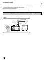
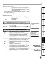
The functions of this unit can be set by the menu screens displayed on the monitor.
Connect this unit with a monitor to check the images to be printed and the images stored in memory.
The following example shows the connection with monitor and camera.
Connect with the necessary signal equipment.
Make sure to turn off the power of the unit and connecting equipment before connection.
CONNECTION WITH MONITOR AND CAMERA
•
•
Make sure to turn off the power before setting.
Never connect CAMERA-IN terminal to a personal computer.
(EXAMPLE)
To S-VIDEO IN terminal
To S-VIDEO OUT terminal
S-VIDEO OUT
To VIDEO IN terminal
To CAMERA-IN
terminal
To VIDEO OUT terminal
VIDEO OUT
Camera
CAMERA-IN
REMOTE
S-VIDEO/IN S-VIDEO/OUT
VIDEO OUT
AC IN
VCP
To camera terminal
10
Monitor (PAL)
BEFORE OPERATION
PRECAUTIONS
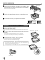
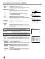
Before printing,
1. Unlock the printing unit. (See below)
2. Install the print paper and ink cassette. (pages 11-14)
PAPER SHEET SET
FEATURES
When using this unit for printing, make sure to use the following types of paper and ink sheet
set.
2 PAPER SHEET SET
Product name
CK900S4P(HX)EU
CK900L4P(HX)EU
Ink sheet size
S size
L size
No. of prints
130
90
Usage
Surface-laminated color print
Surface-laminated color print
CONNECTIONS PREPARATION
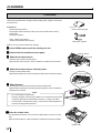
UNLOCK THE PRINTING UNIT
2 RELEASING THE PRINTING UNIT LOCK
1
1 Press down the knob to pull out the tray.
2
2 Shift the printing unit lock switch to the right (UNLOCK). (See page 7.)
PRINTING
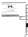
INSTALLATION OF PRINT PAPER
Do not remove the seal on the print paper yet.
Seal
1 Insert the print paper roller with gear on the left.
Press the folder
ADJUSTMENTS
Gear
2
1 as shown right, and set the print paper roller.
2 Set the other side of roller without gear.
TROUBLESHOOTING
1
Front side
OTHERS
1
Left side
Right side
11
BEFORE OPERATION
3 Remove the seal, and insert the edge of the print paper right
arrow marks
below the roller cover with arrow marks towards the front panel.
Make sure to insert the paper straight.
4 Feed the print paper through the paper outlet with your hand.
5 Pull the both side of the print paper to eliminate slack.
Paper
Paper
Paper
INSTALLATION OF INK SHEET
2 INSTALLING THE INK SHEET
Load the ink cassette with the ink sheet roll before inserting the ink cassette into the
printer.
1 Put the ink sheet rollers with flat tops into the holes of ink
colored roller
white roller
cassette.
Put the white roller (rolled with ink sheet) to the ink cassette first.
Then, put the colored roller (without ink sheet) to the ink cassette.
2 Put the other sides of rollers. Set IC at this time.
IC chip with the IC holder is attached to the ink sheet.
Set the IC holder to the ink cassette as shown right.
•
NOTE
Do not remove the IC chip or IC holder from the ink sheet. Removal of the IC
•
will stop the printer from functioning correctly.
Set the projected part of the IC holder to the correct position as shown below.
IC holder
Projected part
12
2 INSTALLING THE INK CASSETTE
PRECAUTIONS
1 Eliminate any slack of the ink sheet.
Hold the colored roller and turn the white roller.
2 Insert the ink cassette with the ink sheet into its compartment.
1
Put the ink cassette of the ink sheet with flat top side to each . Then, set the other
side (with handle) as shown right. When exchanging the ink cassette and so on, remove
1
FEATURES
1
it by holding the handle.(See page 37.)
2
CONNECTIONS PREPARATION
2
2 INSERT THE PRINTING UNIT
1 Push the printing unit until it is locked into place.
2 After plugging the power cord, press POWER button on the front
PRINTING
panel.
3 After the set conditions are displayed on the monitor, press
MEMORY button about 1 second with holding MONITOR button on
the front panel.
ADJUSTMENTS
The print paper is automatically cut after feeding about 10 cm (4 inches).
4 Repeat the above step 3 once or twice.
Fingerprints and dust can be removed by feeding the print paper. The printing unit is
initialized.
NOTE
Make sure to press MONITOR button first for operating
3 and 4.
TROUBLESHOOTING
•
Pressing MEMORY button first operates to memorize the images. When
exchanging the printing paper or ink cassette during using the unit, the
•
recorded images may be erased by pressing MEMORY button first.
Do not feed the print paper more than 2 times. Doing so will not allow the
number of prints indicated on page 11 to be printed.
OTHERS
The installation of print paper and ink cassette is completed.
NOTE
An IC is built in the ink sheet. This is the IC chip, not a battery.
This IC can be thrown away as normal waste.
13
BEFORE OPERATION
NOTE
If the power is turned on and AUTO FEED&CUT on SYSTEM SETUP menu is set to ON,
“SET PAPER” disappears when print paper is set. (For AUTO FEED&CUT setting refer to
page 29.) After inserting ink sheet and closing the printing unit, the print paper is automatically
fed and cut twice.
NOTE
Take the print paper one by one after completing printing. Pull out the tray completely when
using it. If you fail to do so, paper jamming may occur.
Put the tray back when finishing printing.
USAGE AND KEEPING OF PAPER SHEET SET
2 BEFORE PRINTING
•
Fingerprints or dust on the paper’s surface may degrade print quality and cause paper jams.
Immediately after the paper is replaced, 2 images may be printed with a blank part due to
hand’s dust or oil. Refer to Pages 11-12.
•
When print paper is rapidly transferred from a cool place to a hot place, vapor or dew will be
generated on the paper’s surface causing paper jams or degraded print quality. Leave the
print paper in the room to stabilize its temperature before using it.
•
When print paper and ink sheet run out during printing, the printing operation stops and the
error messages such as “CHANGE PAPER” and “CHANGE INK” is displayed on the monitor.
Set new ink sheet or print paper. Refer to Page 34.
2 AFTER PRINTING
•
When the printed paper is touched by a wet hand, the print may be discolored.
•
Fading may occur if the print-face is exposed to organic chemical agents which may affect
print paper (e.g. alcohol, ester, ketone based).
•
Fading will be accelerated upon contact with PVC-based materials (e.g. adhesive tapes,
rubber erasers, etc.).
2 STORAGE
•
•
Avoid storing prints in direct sunlight or places with high humidity.
Leaving the print paper in contact with PVC-based materials causes color of print paper to
•
come off and to be stained.
Never store print paper in places that are close to heater, hot, humid or dusty.
Keep print paper in a place where;
Temperature : 5°C - 30 °C
Humidity
14
: 20 % - 60 %RH
PRINTING (BASIC)
2 SELECTING PRINT SIZE AUTO/S
•
AUTO is selected for initial setting.
•
Select “AUTO” or “S” according to the print size.
AUTO : Selects print size automatically according to the installed ink sheet.
•
S:
Selects S size regardless of the installed ink sheet.
The print size can be set on the menu displayed on the monitor screen.
DISPLAY
PROG.
COLOR
ADJUST
FIELD
/FRAME
PRINT
Q' ty
MENU
SET
CLEAR
FEATURES
•
PRECAUTIONS
BEFORE PRINTING
STOP
Unless the ink sheet size is changed, it is not necessary to select the print size every
time.
1 Press MENU button and MAIN MENU is displayed.
•
•
LAYOUT is displayed.
Normally, “MODE” is selected when opening LAYOUT. When other item is
selected, press
or
button to select “MODE”.
{ }
4 Press [, ] button to select “AUTO” or “S”.
•
Select “AUTO” for normal setting. Select “S” to print S size with L size ink sheet.
MAIN MENU is displayed.
“SAVE PRG 1/2/3/CANCEL” is selected.
•
This menu lets you select a user program memory (1-3) to store your new settings.
6 Press [, ] button to select one of the user memory (1-3) to
memorize the setting.
The program is replaced. In case of keeping the stored program, do not select the user
memory number in which the setting is stored.
LAYOUT
MODE
IMAGES
SIZE
TOP
BOTTOM
LEFT
RIGHT
LAYOUT
MODE
IMAGES
SIZE
TOP
BOTTOM
LEFT
RIGHT
AUTO/S
1/2/4/4D/6/16
: USER
: 0 (0 - -63)
: 0 (0 - -63)
: 0 (0 - -63)
: 0 (0 - -63)
ADJUSTMENTS
•
•
]
]
]
]
MAIN MENU
COLOR
[ ]
INPUT S-VIDEO
LAYOUT
[ ]
PRINT
[ ]
MEMORY POSITION [ ]
SAVE PRG 1 / 2 / 3 / C A N C E L
PRINTING
5 Press SET button.
CONNECTIONS PREPARATION
2 Press {, } button to select “LAYOUT”.
3 Press ] button.
]
]
]
]
MAIN MENU
COLOR
[ ]
INPUT S-VIDEO
LAYOUT
[ ]
PRINT
[ ]
MEMORY POSITION [ ]
SAVE PRG 1 / 2 / 3 / C A N C E L
AUTO/S
1/2/4/4D/6/16
: USER
: 0 (0 - -63)
: 0 (0 - -63)
: 0 (0 - -63)
: 0 (0 - -63)
When CANCEL is selected, the settings are not memorized.
The print size setting is completed.
MAIN MENU
COLOR
[ ]
INPUT S-VIDEO
LAYOUT
[ ]
PRINT
[ ]
MEMORY POSITION [ ]
SAVE PRG 1 / 2 / 3 / C A N C E L
The source image is displayed.
TROUBLESHOOTING
]
]
]
]
7 Press SET button.
MAIN MENU
COLOR
[ ]
INPUT S-VIDEO
LAYOUT
[ ]
PRINT
[ ]
MEMORY POSITION [ ]
SAVE PRG 1 / 2 / 3 / CANCEL
OTHERS
]
]
]
]
15
PRINTING (BASIC)
PRINTING
2 DISPLAY ON THE MONITOR SCREEN
The setting will be displayed on the monitor screen as shown below.
(example)
1
1
3
2
4
This mark illuminates when the memorized image is displayed on the monitor.
When an image from the input signal is displayed, this mark does not illuminate. To
switch the mode, press MONITOR button.
2
These marks show the pages, A and B.
The upper mark shows page A and lower shows B. The mark of the selected page
3
illuminates. To switch the page, press MEMORY PAGE button.
This mark shows color print or black and white print. When black and white print is
4
selected by the B&W of COLOR in MAIN MENU, the mark illuminates.
These marks show the multi image print mode.
From the top to bottom, the mark indicates 1, 2, 4, 6, 16-multi image print.
When 4D mode is selected, the third mark and the marks No. 2 (page numbers)
illuminate. The replacing page illuminates in red.
2 MEMORIZING AND PRINTING AN IMAGE
(When Page Increment is set OFF in the INCREMENT menu)
1 Press MONITOR button to select “MEMORY” on the display.
•
•
The contents of the current memory page will be displayed.
If you do not want to write over the current image, press MEMORY PAGE button to
select another page.
2 Press MONITOR button to select “LIVE ”.
3 When the desired image is shown on screen, press MEMORY
button.
•
The image will be captured and displayed on the screen.
4 Press PRINT button.
16
PRECAUTIONS
2 SELECTING MEMORIZED IMAGE TO PRINT
1 Press MONITOR button to select “MEMORY” on the display.
•
The contents of the current memory page will be displayed.
FEATURES
2 Press the MEMORY PAGE button to select page A or B.
3 Press the PRINT button.
MULTI
CONNECTIONS PREPARATION
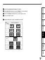
2 IMAGE SIZE AND LAYOUT OF MEMORY PAGES
PRINT EXAMPLE
1
2
PRINTING
4
ADJUSTMENTS
4D
6
TROUBLESHOOTING
16
OTHERS
17
PRINTING (BASIC)
2 MULTIPLE COPY OR CONTINUOUS PRINTING
Multiple copies of a memorized image can be made by setting the number of prints to
more than one. The print quantity can be set for up to 200 prints or for continuous
printing until the paper or ink sheet is used up. Multiple quantity printing can be
cancelled if needed.
NOTE
The number of prints is displayed on the monitor for 3 seconds after pressing
buttons.
{, }
1 Press PRINT Q’ty {,} button to set the number of sheets to be
printed.
•
•
The number will increase by pressing
The number switches in the order of;
{ and decrease by pressing }.
1←→2← • • • → 9 ←→ 10 ←→ 20 ←→ 30 ←→ 40 ←→ 50 ←→ 100 ←→ 200 ←→ C ←→ 1
When you set “C”, continuous printing will be done until the paper or ink sheet is
used up.
2 Press PRINT button.
•
The number of prints you set is printed.
•
During continuous printing (except for selecting “C”), the set number will be counted
down every time one sheet is printed. When printing is completed, the counter will
be reset to the original set number. This will not reset when turning off the power (It
will not be reset to “1”.)
•
If you wish to reset the number of prints to 1;
• If you wish to reset the number of prints to 1, press STOP buttons.
•
If you wish to stop printing;
• Press PRINT Q’ty
or
{ } button. After printing the current page, the
{ or } button is also
counter will be reset to “1”. Pressing PRINT Q’ty
available to cancel the reserved printing.
•
If you wish to stop printing without completing the current page, press STOP
button. The incomplete image will be printed out.
NOTE
•
If a blackish image is continuously printed, the internal temperature may rise and
cause the unit to switch to a stand-by condition during printing. In this case, an error
message “OVER HEAT” will be displayed on the monitor. Wait until the error message
goes off. When temperature drops and the message goes off, printing resumes.
18
PRINTING (SPECIAL)
Various types of printing are available by setting on the menu screen (MAIN MENU and SERVICE MENU).
In this section, some examples of special prints are given.
PRECAUTIONS
For each setting, see pages 22-23.
MULTI PRINT
MULTI PRINT is the function which 2, 4, 6 or 16 images can be printed on a sheet.
Use LAYOUT of MAIN MENU for setting. See page 26.
FEATURES
SEPARATE PRINT
The SEPARATE print function inserts a white frame between 2 or more images.
•
Use LAYOUT2 of SERVICE MENU for setting. See page 30.
CONNECTIONS PREPARATION
•
NOTE
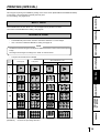
The distance between images in multi print is different between on the monitor and the printed
image.
The image size changes according to the “SIZE” in LAYOUT menu.
•
The prints shown below are available.
Setting of
the No. of
images
S size prints
When SEPARATE : ON
L size prints
S size prints
L size prints
1
PRINTING
2
ADJUSTMENTS
4
4D
TROUBLESHOOTING
6
OTHERS
16
(EXAMPLE)
“A” shows the print image direction.
19
PRINTING (SPECIAL)
EXTERNAL REMOTE TERMINAL 1
3
2
1
The image can be stored in memory by sending the remote signal through the external
remote terminal on the rear panel. When the MEM&PRN(MEMORY & PRINT) function
is set to ON, the image will be printed after being stored in memory.
• Make out the necessary circuit to use this function by referring to the following.
Circuit inside and pin No.
2 EXTERNAL REMOTE TERMINAL SIGNAL ALLOCATION (STEREO
JACK)
Pin No.
1
2
3
•
Function
Ground
MEMORY
BUSY1
Description
Earth
Memory : When the signal becomes “LOW” from “HIGH”, the
image is stored in memory. (When the signal has
been “LOW” for 60ms or more, the image is stored
in memory.) See page 31.
Refer to the BUSY LEVEL setting of REMOTE SET in SERVICE
MENU. See page 32.
When the signal from BUSY terminal is received with TTL level, keep the following.
| IOL | = 2mA or less, | IOH | = 1mA or less
| IOL | means the current flowing into the unit at Low output, | IOH | means the
current flowing out of the unit at High output.
23 1
Plug pin No.
Circuit inside the VCP
DC5V
DTC124EK
To VCP
10kΩ
100Ω
22kΩ
2MEMORY
22kΩ
DC5V
DMC2838
10kΩ
DTC124EK
100Ω
3 BUSY
22kΩ
From VCP
22kΩ
EXTERNAL REMOTE TERMINAL 2
12
The image can be stored in memory and printed by sending the remote signal through
the external remote terminal on the rear panel.
• Make out the necessary circuit to use this function by referring to the following.
34
2 EXTERNAL REMOTE TERMINAL SIGNAL ALLOCATION (MINI
DIN8PIN)
Pin No.
1
2
Function
Description
Ground
MEMORY
Earth
Memory : When the signal becomes “LOW” from “HIGH”, the
67 8
Pin No.
image is stored in memory. (When the signal has
been “LOW” for 60ms or more, the image is stored
BUSY2
in memory.) See page 31.
Refer to the BUSY LEVEL setting of REMOTE SET in
4
BUSY1
SERVICE MENU. See page 32.
Refer to the BUSY LEVEL setting of REMOTE SET in
5
PRINT
SERVICE MENU. See page 32.
When the signal becomes “LOW” from “HIGH”, the image is
3
6
7
8
•
stored in memory. (When the signal has been “LOW” for 60ms
or more, the image is stored in memory.
Circuit inside the VCP
DC5V
DTC124EK
To VCP
10kΩ
22kΩ
22kΩ
100Ω
2MEMORY
DC5V
74LVC125
10kΩ
100Ω
From VCP
3 BUSY2
4 BUSY1
TTL level
DC5V
REMOTE
Unused
DC3V
The same functions as the supplied remote control unit can
be controlled.
Power supply for the remote control unit DC 1mA Max.
74LVC125
10kΩ
100Ω
To VCP
To VCP
TTL level
1kΩ
56kΩ
When the signal from BUSY terminal is received with TTL level, keep the following.
| IOL | = 2mA or less, | IOH | = 1mA or less
| IOL | means the current flowing into the unit at Low output, | IOH | means the
current flowing out of the unit at High output.
20
5
5 PRINT
6 REMOTE
2 PIN NO. 6 REMOTE TERMINAL
01:
[ button
02:
{
] button
03:
} button
04:
{ button
PRECAUTIONS
By sending the following remote control codes from pin No.6, the same functions as the wired
remote control unit supplied can be controlled.
1.6 ms
08: PRINT Q’ty
button
09*
0A*: MENU button
0B*: CLEAR button
0C: PRINT Q’ty
0D*
0E*: SET button
12*: PROGRAM button 13*: PRINT button
0F*: STOP button
15*: FIELD/FRAME button
16*: COLOR ADJ button 17*: MEMORY button
1C*: MEMORY PAGE button
18*: DISPLAY button
1D*: MONITOR button
} button
0.4 ms
FEATURES
3.2 ms
In case of the codes with * mark, 5 words are sent.
Input signal level
Input timing
:
:
CONNECTIONS PREPARATION
2 TIMING CHART
0.4 ms
TTL
1 word 38.4 ms
1
1
0
0
1
0
1 word = 38.4 msec.
(EXAMPLE) Print code
= 13 = 0 1 0 0 1 1
CAMERA-IN TERMINAL
Pin No.
Signal line name
Pin No.
PRINTING
2 CAMERA-IN TERMINAL SIGNAL ALLOCATION (25 PIN)
Signal line name
14
15
+12V (Max. 1A)
GND
3
4
RXD
RTS
16
17
GND
GND
5
6
CTS
DSR
18
19
GND
GND
7
8
GND
NC
20
21
DTR
GND
9
10
GND
Comp.Video OUT
22
23
GND
GND
11
12
GND
S-video (C) IN
24
25
GND
REMOCON
13
S-Video (Y) IN
TROUBLESHOOTING
GND
TXD
ADJUSTMENTS
1
2
OTHERS
21
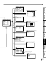
SETTING THE FUNCTIONS (MENU CHART)
MONITOR DISPLAY CHART
OPERATION
is reference page.
p
COLOR ADJ
SELECT COLOR/B&W
BRT
: 0
CONT : 0
R-SUB : 0 C
G-SUB : 0 M
B-SUB : 0 Y
[ ]
CENTER
[ ]
CANCEL
]]
Press [ , ] button to change the value,
select the mode or switch the item.
R
G
B
Select an item with { ,} button.
Monitor display
is the name of button
on remote control unit.
is the name of button
on front panel.
Front panel
POWER
ON
p26
STOP
p24
Set conditions display
MAIN MENU display
MAIN MENU
COLOR ADJ
INPUT S-VIDEO
LAYOUT
PRINT
MEMORY POSITION
MENU
SET
DISPLAY
SAVE PRG
]]
[] ]
[] ]
[] ]
]]
[
1/2/3/CANCEL
Color adjustment display
COLOR ADJ
SELECT COLOR/B&W
BRT
: 0
CONT : 0
R-SUB : 0 C
G-SUB : 0 M
B-SUB : 0 Y
[ ]
CENTER
[ ]
CANCEL
R
G
B
MENU
*1
SET
p26
Changes to Y-SUB,
M-SUB, C-SUB
when selecting
SELECT : B&W
Layout setting display 1
LAYOUT
MODE
IMAGES
SIZE
TOP
BOTTOM
LEFT
RIGHT
AUTO/S
1/2/4/4D/6/16
: USER
: 0 (0 ~ -63)
: 0 (0 ~ -63)
: 0 (0 ~ -63)
: 0 (0 ~ -63)
Source image
p27
DISPLAY
Print setting display1
PRINT
APT
DIR
MIRROR
p27
S/N/H1/H2
NOR/REV
OFF/ON
Memory/Position setting display
MEMORY POSITION
LINE
OFF/ON
H-POSI
0
V-POSI
0
*1 When going back to MAIN MENU or
SERVICE MENU without saving the setting,
press MENU button.
To Set Conditions display
22
p29
System setting display
p29
PRECAUTIONS
SYSTEM SETUP
INCREMENT OFF/PAGE
BUZZER
OFF/T1/T2
REMAINING BUZZER
OFF/0
REMAINING SCREEN
OFF/ON
AUTO FEED&CUT
OFF/ON
PAPER HOLD
OFF/ON
INIT PROG ALL/MAIN/SERVICE
INITIALIZE OFF/GO
Gamma level setting display
GAMMA ADJ INIT:[CLEAR]
COLOR
ALL/EACH
SELECT
R/G/B
Hi
0
Mid
0
Low
0
POINT 64 128 192
Layout setting display 2
LAYOUT2
SEPARATE
MARGIN CUT
p28
FEATURES
p30
Displays only when
selecting COLOR : EACH
OFF/ON
OFF/ON
]]
]]
]]
]]
]
]
SET
p30
MENU
*1
SET
p30
Input signal setting display
INPUT
FIELD
AFC
AGC
Analog color adjustment display
ANALOG COLOR ADJ
INPUT
COLOR/B&W
BRT
:0
CONT
:0
R-SUB
:0C
G-SUB
:0M
B-SUB
:0Y
COLOR
:0
CENTER
[ ]
CANCEL
[ ]
R
G
B
NOR/REV
OFF/ON
OFF/ON
p31
Output signal setting display
OUTPUT
MONI R-SUB
MONI B-SUB
0
0
PRINTING
p31
CONNECTIONS PREPARATION
SERVICE MENU display
SERVICE MENU
SYSTEM
[ ]
GAMMA ADJ
[ ]
LAYOUT2
[ ]
ANALOG COLOR ADJ [ ]
INPUT
[ ]
OUTPUT
[ ]
KEY SET
[ ]
RS232C
[ ]
REMOTE
[ ]
PREVIOUS ERROR
[ ]
SAVE PRG 1/2/3/CANCEL
Button function setting display
p32
ADJUSTMENTS
KEY SET
KEY LOCK OFF/ON
MEM&PRN OFF/ON/R1/R2
MEM&STOP OFF/PAGE
MEM&MONI OFF/ON
KEEP MONI OFF/ON
AUTO CLEAR OFF/AFTER PRN
CLEAR KEY PAGE/ALL
RS-232C setting display
RS232C SET
BAUD RATE 1200/2400/4800/9600
TROUBLESHOOTING
p32
Remote signal setting display
When either one of them is set to OFF,
the other is available for setting.
p33
OTHERS
REMOTE SET
BUSY LEVEL
LOW/HIGH
BUSY1,2 SELECT
PRINTING
OFF/1/2/1&2
MECHA ERR
OFF/1/2/1&2
MEDIA ERR
OFF/1/2/1&2
MEMORY STOP OFF/1/2/1&2
STROBE 1V
OFF/1/2/1&2
STROBE 2V
OFF/1/2/1&2
REMAINING
OFF/1/2/1&2
Previous error display
PREVIOUS ERROR
NO ERROR
NO ERROR
NO ERROR
NO ERROR
23
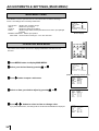
ADJUSTMENTS & SETTINGS (MAIN MENU)
MAIN MENU ITEMS
MAIN MENU is used to open sub-menus. The functions are set with the following 5
menus. The settings can be saved by SAVE PRG.
COLOR ADJ
INPUT
LAYOUT
PRINT
Adjusts color of printing image
Selects the input signal
Adjusts the image layout setting
Adjusts image outline, selects print direction and mirror print (left/right
inversed)
MEMORY POSITION Selects print position
SAVE PRG Stores the above settings in 1 of 3 user memories
]
]
]
]
MAIN MENU
COLOR ADJ
[ ]
INPUT S-VIDEO
LAYOUT
[ ]
PRINT
[ ]
MEMORY POSITION [ ]
SAVE PRG 1 / 2 / 3 / CANCEL
Monitor display
DISPLAY
OPERATING MAIN MENU
COLOR
ADJUST
PROG.
FIELD
/FRAME
Use buttons on the remote control unit to display MAIN MENU and select and set
functions.
PRINT
Q' ty
MENU
SET
CLEAR
1 Press MENU button to display MAIN MENU.
2 Select your desired item by pressing or
{
3 Press
]
]
]
]
MAIN MENU
COLOR ADJ
[ ]
INPUT S-VIDEO
LAYOUT
[ ]
PRINT
[ ]
MEMORY POSITION [ ]
SAVE PRG 1 / 2 / 3 / CANCEL
}.
(EXAMPLE) Selecting LAYOUT display
]
button to open a sub menu.
4 Select an item you wish to adjust by pressing
5 Press
[
{
or }.
or ] button to select an item or change value.
If you press MENU button, the settings will be canceled and MAIN MENU is displayed.
24
STOP
LAYOUT
MODE
IMAGES
SIZE
TOP
BOTTOM
LEFT
RIGHT
AUTO/S
1/2/4/4D/6/16
: USER
: 0 (0 ~ -63)
: 0 (0 ~ -63)
: 0 (0 ~ -63)
: 0 (0 ~ -63)
LAYOUT
MODE
IMAGES
SIZE
TOP
BOTTOM
LEFT
RIGHT
AUTO/S
1/2/4/4D/6/16
: USER
: 0 (0 ~ -63)
: 0 (0 ~ -63)
: 0 (0 ~ -63)
: 0 (0 ~ -63)
LAYOUT
MODE
IMAGES
SIZE
TOP
BOTTOM
LEFT
RIGHT
AUTO/S
1/2/4/4D/6/16
: USER
: 0 (0 ~ -63)
: 0 (0 ~ -63)
: 0 (0 ~ -63)
: 0 (0 ~ -63)
6 Press SET button.
PRECAUTIONS
MAIN MENU is displayed.
“SAVE PRG 1/2/3/CANCEL” is selected.
This menu lets you select a user program memory (1-3) to store your new settings.
7 Press
[ or ] button to select the user memory numbers of 1, 2
or 3 to store the setting.
]
]
]
]
MAIN MENU
COLOR ADJ
[ ]
INPUT S-VIDEO
LAYOUT
[ ]
PRINT
[ ]
MEMORY POSITION [ ]
SAVE PRG 1 / 2 / 3 / CANCEL
FEATURES
The program is replaced. In case of keeping the stored program, do not select the
user memory number in which the setting is stored.
If you wish to cancel the setting, select CANCEL and press SET button.
CONNECTIONS PREPARATION
8 Press SET button.
When selecting PRG1 to set, “1” is chosen. When memorizing in a different user
memory number, select the number of the program.
•
As the program is replaced, it is recommended that the previous program number
is not selected in the step .
•
The memorized program will be selected by pressing PROG button so that you
can adjust the program as you wish. However, you cannot change the setting of
•
7
selected program during printing.
The image will be printed according to the selected memory program.
PRINTING
ADJUSTMENTS
TROUBLESHOOTING
OTHERS
25
ADJUSTMENTS & SETTINGS (MAIN MENU)
COLOR ADJ Color adjustment display
•
COLOR ADJ
SELECT COLOR/B&W
BRT
: 0
CONT : 0
R-SUB : 0 C
G-SUB : 0 M
B-SUB : 0 Y
[ ]
CENTER
[ ]
CANCEL
The color of the source image and memorized image can be adjusted.
SELECT
COLOR
B&W
BRT (Bright)
CONT (Contrast)
R-SUB
Selects color print or black and white print.
Color print
Black and white print (The monitor shows in colors.)
Adjusts brightness of the printing image.
Adjusts contrast of the printing image.
Adjusts red-subcontrast of the printing image. Red is added with ] and
blue is added with [.
G-SUB
Adjusts green-subcontrast of the printing image. Green is added with ]
and pink is added with [.
B-SUB
Adjusts blue-subcontrast of the printing image. Blue is added with ]
and yellow is added with [.
CENTER
When pressing ], the values of BRT, CONT, R-SUB G-SUB and B-SUB
will be reset to 0.
CANCEL
Initializes each setting in COLOR ADJ.
• When selecting B&W, R-SUB, G-SUB and B-SUB change to Y-SUB, M-SUB, C-SUB. By
changing each value, adjustment of gray color is available.
• When SELECT is changed from COLOR to B&W, the set values of R-SUB, G-SUB and BSUB function as the density of gray color.
]]
LAYOUT Layout setting display
MODE
Selects the print size. Normally select the ink sheet size which installed in
this unit. (See page 11 for the print paper.)
L size ink sheet.
When S size ink sheet is installed, S size is automatically set.
S size ink sheet or S size printing with L size ink sheet.
AUTO
S
IMAGES
1
2
4
4D
6
16
LAYOUT
MODE
IMAGES
SIZE
TOP
BOTTOM
LEFT
RIGHT
Selects the number of images on a sheet.
1-image on a sheet.
2-images on a sheet.
4-images on a sheet (4 same images)
4-images on a sheet (2 different images)
6-images on a sheet
16-images on a sheet (When printing on a L size paper, the right
and left side of the image will be clipped.)
SIZE : USER
TOP/BOTTOM/LEFT/RIGHT
Sets the printing area of the image. Adjust the size with [ or ]
button. See the examples on the next page.
TOP
Shifts the upper end of the image (setting area : 0 to -63)
BOTTOM
Shifts the lower end of the image (setting area : 0 to -63)
LEFT
Shifts the left end of the image (setting area : 0 to -63)
RIGHT
Shifts the right end of the image (setting area : -0 to -63)
MAX. SIZE
S
1
100 x 75
2
70 x 50
4/4D
50 x 37.5
6
37.5 x 30
16
25 x 18.7
dots/ mm
Left, Right
2.844
4.096
5.689
6.827
11.378
MAX. SIZE
Top, Bottom
x
x
x
x
x
1.778
2.560
3.556
4.267
7.111
L
1
130
2
100
4/4D
65
6
50
16 32.5
Example
To change 50mm x 37.5mm (S size 4-multi image) to 45mm x 35mm;
Change LEFT or RIGHT value to -28
(5.689x(50-45)=28.445)
Change TOP or BOTTOM value to -9
26
(3.556x(37.5-35)=8.89)
x 100
x 65
x 49.5
x 42.8
x 24.8
dots/ mm
Left, Right
2.275
2.844
4.551
5.120
9.102
Top, Bottom
x
x
x
x
x
1.422
1.778
2.844
3.200
5.689
AUTO/S
1/2/4/4D/6/16
: USER
: 0 (0 ~ -63)
: 0 (0 ~ -63)
: 0 (0 ~ -63)
: 0 (0 ~ -63)
R
G
B
APT (Aperture)
S (SOFT)
N (NORMAL)
H1 (HARD 1)
H2 (HARD 2)
Controls apertures and reinforces or softens the contour of image.
Softens the contour.
Does not reinforce the contour.
Reinforces the contour.
Reinforces the contour more.
PRECAUTIONS
PRINT Print setting display
PRINT
APT
S/N/H1/H2
DIR
NOR/REV
MIRROR OFF/ON
FEATURES
DIR (Print direction) Selects printing direction.
NOR
The margin is made on the lower position.
REV
The margin is made on the upper position.
MIRROR
OFF
ON
Selects the mirror (left/right inversed) prints.
Normal print
Mirror print
CONNECTIONS PREPARATION
Examples of SIZE, DIR and MIRROR setting
(The image is limited in printing with white by SIZE setting.)
Standard print
When the values of
BOTTOM and LEFT
are small
When the values of TOP
and RIGHT are small
and DIR is ON
When the values of TOP
and RIGHT are small and
MIRROR and DIR are ON
PRINTING
When the values of TOP
and RIGHT are small and
MIRROR is ON
When the values of
TOP and RIGHT are
small
•
The print area settings made with this menu can be memorized as a user program
setting.
ADJUSTMENTS
MEMORY POSITION Memory and Position setting display
MEMORY POSITION
LINE
OFF/ON
H-POSI
0
V-POSI
0
H-POSI
•
Changes the horizontal start position of input signal
The whole data image can be moved horizontally by changing the setting
number.
Setting area -10 ~ +15
Setting below -11 may cause disabilities of memory, or switching memory display and
monitor display during printing.
TROUBLESHOOTING
LINE
Selects whether showing a frame of print area or not.
OFF
A frame of print area is not shown.
ON
A frame of print area is shown.
• When this menu is set to OFF, FIELD/FRAME button on the remote control unit is not available.
LINE
H-POSI
+
V-POSI
OTHERS
+
V-POSI
•
Changes the vertical start position of input signal
The whole data image can be moved vertically by changing the setting
number.
Setting area -10 ~ +3
Setting below -11 may cause disabilities of memory, or switching memory display and
monitor display during printing.
27
ADJUSTMENTS & SETTINGS (SERVICE MENU)
SERVICE MENU ITEMS
SYSTEM
Sets page increment, buzzer and remaining of ink sheet.
GAMMA ADJ
Sets gamma curve level.
LAYOUT2
Adjusts print layout setting.
ANALOG COLOR ADJ
Adjusts analog input signal image.
INPUT
Sets even/odd number of FIELD, adjusts display, etc.
OUTPUT
Sets sub-contrast of the monitor.
KEY SET
Selects the functions of the buttons and function of remote
terminal.
RS232C
Selects baud rate.
REMOTE
Selects remote signal.
PREVIOUS ERROR Shows error history.
]
]
]
]
]
]
]
]
]
]
SERVICE MENU
SYSTEM
[ ]
GAMMA ADJ
[ ]
LAYOUT2
[ ]
ANALOG COLOR ADJ [ ]
INPUT
[ ]
OUTPUT
[ ]
KEY SET
[ ]
RS232C
[ ]
REMOTE
[ ]
PREVIOUS ERROR
[ ]
SAVE PRG 1/2/3/CANCEL
ALARM
SHEET
PAPER
S-VIDEO
OPERATING SERVICE MENU
1 Press MENU button on the remote control unit.
The MAIN MENU is displayed.
2 Press STOP buttons on the remote control unit at the same time.
The SERVICE MENU is displayed.
PRINT
Q' ty
MENU
SET
CLEAR
3 Select your desired item by pressing
{ or }
on the remote control
unit.
4 Press button to open a sub menu.
5 Select an item you wish to adjust by pressing or .
6 Press or button to select an item or change value.
7 Press SET button.
]
{
[
}
“SAVE PRG 1/2/3/CANCEL” is selected.
This menu lets you select a user program memory (1-3) to store your new settings.
or ] button to select the user memory numbers of 1, 2
or 3 to store the setting.
[
The program is replaced. In case of keeping the stored program, do not select the
user memory number in which the setting is stored.
If you wish to cancel the setting, select CANCEL.
9Press SET button.
When selecting PRG1 to set, “1” is chosen. When memorizing in a different user
memory number, select the number of the program.
The setting is completed and the normal screen is displayed.
28
]
]
]
]
]
]
]
]
]
]
SERVICE MENU
SYSTEM
[ ]
GAMMA ADJ
[ ]
LAYOUT2
[ ]
ANALOG COLOR ADJ [ ]
INPUT
[ ]
OUTPUT
[ ]
KEY SET
[ ]
RS232C
[ ]
REMOTE
[ ]
PREVIOUS ERROR
[ ]
SAVE PRG 1/2/3/CANCEL
(EXAMPLE) Selecting SYSTEM SETUP display
]
SERVICE MENU is displayed.
8 Press
STOP
SYSTEM SETUP
INCREMENT OFF/PAGE
BUZZER
OFF/T1/T2
REMAINING BUZZER
OFF/0
REMAINING SCREEN
OFF/ON
AUTO FEED&CUT
OFF/ON
PAPER HOLD
OFF/ON
INIT PROG ALL/MAIN/SERVICE
INITIALIZE OFF/GO
INCREMENT
OFF
Page increment is not available.
PAGE
Every time pressing MEMORY button, memory page goes to the next
page and image will be memorized on it.
BUZZER
SYSTEM SETUP
INCREMENT OFF/PAGE
BUZZER
OFF/T1/T2
REMAINING BUZZER
OFF/0
REMAINING SCREEN
OFF/ON
AUTO FEED&CUT
OFF/ON
PAPER HOLD
OFF/ON
INIT PROG ALL/MAIN/SERVICE
INITIALIZE OFF/GO
FEATURES
OFF
T1
T2
Selects sounds the buzzer when pressing the buttons on the VCP
and remote control unit.
Does not sound the buzzer
Sounds the buzzer (Tone 1)
Sounds the buzzer (Tone 2)
PRECAUTIONS
SYSTEM SETUP System setting display
REMAINING BUZZER
CONNECTIONS PREPARATION
Informs the number of remaining ink sheet by a buzzer
tone.
OFF
Does not sound the buzzer.
0 ~ 10
The buzzer sounds three times when 0 ~ 10 ink sheet are left
(available to set 1 sheet each).
When the number of remaining ink sheet reaches to the set value, the
buzzer starts sounding at printing each time.
• If a paper jam occurs, the remaining ink sheet may not be informed correctly.
• Make sure to replace the print paper and ink sheet at the same time.
REMAINING SCREEN
Selects displaying the remains of ink sheet on the monitor or not.
OFF
Does not display the remains of ink sheet on the monitor.
ON
Displays the remains of ink sheet on the monitor.
• If a paper jam occurs, the remains of the ink sheet may be different from the indication
on the monitor.
PRINTING
AUTO FEED&CUT Selects automatically feeding and cutting the print paper or not.
OFF
Does not feed and cut the print paper.
ON
When setting the print paper, this unit automatically feeds and cuts it twice
after closing the front door.
ADJUSTMENTS
PAPER HOLD
Sets to hold the printed paper or not.
OFF
PAPER HOLD is not available.
ON
Printed paper is held at the print outlet after cut. Pull the paper out when
necessary.
It is recommended not to leave the printed paper holding at the print outlet.
Do not turn off the power while holding paper or some malfunction may
occur.
You can not use remote control unit with holding paper.
INIT PROG (Initialize program)
ALL
Mode to initialize the programs in MAIN MENU and SERVICE MENU.
MAIN
Mode to initialize the programs in MAIN MENU.
SERVICE Mode to initialize the programs in SERVICE MENU.
TROUBLESHOOTING
INITIALIZE
OFF
GO
Starts initializing. When SET button is pressed, initializing starts.
GAMMA ADJ Adjusting gamma curve display
OTHERS
INIT :[CLEAR]
Initializes each setting
COLOR
Selects the adjusting gamma level.
ALL
Adjusting gamma level for all colors.
EACH
Adjusting gamma level for each color of R, G, B.
GAMMA ADJ INIT: [CLEAR]
COLOR
ALL/EACH
SELECT
R/G/B
Hi
0
Mid
0
Low
0
POINT 64 128 192
29
ADJUSTMENTS & SETTINGS (SERVICE MENU)
SELECT
R
G
B
Is displayed when selecting EACH in COLOR.
Adjusting gamma level for red.
Adjusting gamma level for green.
Adjusting gamma level for blue.
Changing gamma curve:
Use the {, } buttons on the remote control unit to select the Hi/Mid/Low gamma
point to set.
Also use [, ] buttons to input setting level.
NOTE
It takes time to set the gamma value by CPU. Wait until the normal display is
shown after pressing SET button.
LAYOUT2 Layout setting display 2
SEPARATE
OFF
ON
Selects whether a white frame is added to each print or not.
Prints without white frame. ( A white frame appears according to the settings
LAYOUT2
SEPARATE
OFF/ON
MARGIN CUT OFF/ON
of LAYOUT)
Prints with white frame.
MARGIN CUT
Cuts the margin of the printed paper.
• This function is very convenient to stick the printed image on the card. The figure
shows S size print paper setting.
OFF
Margin is not cut.
ON
Margin is cut.
Gray part is
cut when
MARGIN CUT
is ON.
ANALOG COLOR ADJ Analog color adjustment display
•
This menu is used to adjust the image of analog input signal before storing in the
memory.
INPUT
B&W
COLOR
BRT (Bright)
CONT (Contrast)
R-SUB
G-SUB
B-SUB
COLOR
CENTER
Selects black and white image or color image.
The image on the display becomes black and white.
Color image
Adjusts the brightness of the printing image.
Adjusts the contrast of the printing image.
Adjusts red-subcontrast of the printing image. Red is added with
] and blue is added with [.
Adjusts green-subcontrast of the printing image. Green is added
with ] and pink is added with [.
Adjusts blue-subcontrast of the printing image. Blue is added
with ] and yellow is added with [.
Adjusts density of the printing image. The color of the image
gets deeper with ] and lighter with [.
Initializes each setting. When pressing ], the values of BRT,
CONT, R-SUB, G-SUB, B-SUB and COLOR will be reset to 0.
ANALOG COLOR ADJ
INPUT
COLOR/B&W
BRT
:0
CONT
:0
R-SUB
:0C
G-SUB
:0M
B-SUB
:0Y
COLOR
:0
CENTER
[ ]
CANCEL
[ ]
INPUT Input signal setting display
• Set this menu before memorizing image.
FIELD
The odd and even field lines will be reversed depending on the input
interlaced signal. Printing image is not clear so that the odd and even
field lines may be reversed depending on the input interlaced signal. In
this case, FIELD is set to “REV.” (The image disorder cannot be seen
in monitor display.)
NOR(Normal)
Not reversed
REV(Reverse) Reverse the even and odd numbers of FIELD
30
INPUT
FIELD
AFC
AGC
NOR/REV
OFF/ON
OFF/ON
R
G
B
PRECAUTIONS
AFC(Automatic frequency control)
The image distortion on the top may occur when the VCR
image is special input such as in pause, field-by-field
playback, or FF playback mode. Also, the image is not
printed correctly because of a weak TV signal. In this case,
set the AFC function to “ON.”
• The image distortion on the top may occur by the special signals when AFC is set to
“ON”. In this case, set it to “OFF.”
OFF
AFC is invalid
ON
AFC is available
FEATURES
CONNECTIONS PREPARATION
AGC(Automatic gain control)
This function is to automatically adjust a dark picture in
brightness and prints with sharp contrast. Peak level of an
input signal is detected and signals width is standardized to
the appropriate value.
OFF
AGC is invalid
ON
AGC is available
OUTPUT Output signal setting display
MONI R-SUB
MONI B-SUB
Adjusts red-subcontrast on the monitor. Red is added with ] and
blue is added with [.
Adjusts blue-subcontrast on the monitor. Blue is added with ] and
yellow is added with [.
OUTPUT
MONI R-SUB
MONI B-SUB
0
0
KEY SET Button function setting display
Makes the function on the remote control unit buttons invalid.
All buttons on the remote control unit are available.
The function on the remote control unit buttons, except MEMORY,
PRINT, MONITOR and MEMORY PAGE are not available.
When pressing MENU button, KEY SET menu is displayed.
When pressing MENU button, only selecting OFF/ON of KEY
LOCK is available.
KEY SET
KEY LOCK OFF/ON
MEM&PRN OFF/ON/R1/R2
MEM&STOP OFF/PAGE
MEM&MONI OFF/ON
KEEP MONI OFF/ON
AUTO CLEAR OFF/AFTER PRN
CLEAR KEY PAGE/ALL
ADJUSTMENTS
Memory
source
Memorizing
Not printing
Memory
source
OTHERS
Memorizing
TROUBLESHOOTING
MEM&PRN (Memory and Print)
When pressing MEMORY button, the image is automatically printed
after the image is stored in the memory. When selecting 4D at
IMAGES, printing will be done after the last image is stored in
memory.
OFF
MEMORY button functions individually. The image is memorized
without printing.
ON
Automatically prints after memorizing.
R1
R1
When a signal inputted through a memory key (pin No. 2) of the
remote terminal on the rear panel is switched to “low” level from
Display
Source
“high” for the first time, a memory image is displayed. Then at the
Remote terminal input
second time, a source image is displayed without printing the
memory image.
R2
R2
On the KEEP MONI OFF status, when a signal inputted through a
memory key (pin No. 2) of the remote terminal is switched to “low”
source
Display
level from “high” for the first time, a memory image is displayed.
Remote terminal input
Then at the second time, a source image is displayed and the
memory image is printed.
PRINTING
KEY LOCK
OFF
ON
Printing
31
ADJUSTMENTS & SETTINGS (SERVICE MENU)
MEM&STOP (Memory and Stop)
OFF
The next image is overlaid in the memory.
PAGE
Automatic increment stops when all pages become full. To overlay
a new image, print or clear the memorized image.
MEM&MONI (Memory and Monitor)
Switches the monitor display between the source image and
memory image after memorizing.
OFF
Displays the source image.
ON
Displays the memory image. (Initial setting)
• When KEEP MONI is set to OFF, the source image will be
displayed when starting printing.
KEEP MONI
OFF
ON
Selects the image displayed on the monitor during printing
Displays the source image after starting printing.
Displays the source image after starting printing, when indicating it
before printing. Displays the memory image after starting printing,
when indicating it before printing.
MEM&MONI : OFF
About 2 seconds
Display
SOURCE MEMORY SOURCE
MEMORY
MEM&MONI : ON
KEEP MONI : OFF
Display
SOURCE MEMORY SOURCE
MEMORY
MEM&MONI : ON
KEEP MONI : ON
Display SOURCE
AUTO CLEAR
OFF
AFTER PRN
CLEAR KEY
PAGE
The printed memory image is not cleared.
The printed memory image is cleared after completing printing.
PRINT
MEMORY
MEMORY
PRINT
Pressing CLEAR button on the remote control unit, images of the
memorized page being selected are cleared.
Pressing CLEAR button on the remote control unit, all of the stored
images are cleared.
ALL
RS232C SET RS-232C setting display
BAUD RATE
RS-232C SET
BAUD RATE :1200/2400/4800/9600
Sets the baud rate of RS-232C.
Set the baud rate according to the connecting device.
REMOTE SET Remote signal setting display
BUSY LEVEL
Low
High
Selects how to output the BUSY signal of the remote
terminals 1 and 2 on the rear panel.
The VCP cannot accept the remote input signal when the signal is “LOW”.
The VCP cannot accept the remote input signal when the signal is “HIGH”.
BUSY 1,2 SELECT
Selects when the BUSY signal of the remote terminals 1 and
2 output on the rear panel.
PRINTING
Outputs BUSY signal during printing.
MECHA ERR
Outputs BUSY signal when a mechanical error occurs in this unit or
IC chip is not installed.
MEDIA ERR
Outputs BUSY signal when an error for paper or ink sheet occurs.
MEMORY STOP Outputs BUSY signal when MEMORY button is not functioning.
STROBE 1V
After outputting BUSY signal, memory is taken in by waiting to 1
vertical period.
STROBE 2V
After outputting BUSY signal, memory is taken in by waiting to 2
vertical periods.
REMAINING
Outputs BUSY signal while the remains of ink sheet becomes the
value set in REMAINING BUZZER.
• When either STROBE 1V or STROBE 2V is set to OFF, the other is available for
setting.
32
REMOTE SET
BUSY LEVEL
LOW/HIGH
BUSY1,2 SELECT
PRINTING
OFF/1/2/1&2
MECHA ERR
OFF/1/2/1&2
MEDIA ERR
OFF/1/2/1&2
MEMORY STOP OFF/1/2/1&2
STROBE 1V
OFF/1/2/1&2
STROBE 2V
OFF/1/2/1&2
REMAINING
OFF/1/2/1&2
2
SYNCHRONOUS SETTING FOR MEMORY
PRECAUTIONS
STROBE : 1V, BUSY LEVEL : HIGH in REMOTE SET of SERVICE MENU
V SYNC
Image memorizing
BUSY OUTPUT
a
b
FEATURES
STROBE : 2V, BUSY LEVEL : HIGH in REMOTE SET of SERVICE MENU
V SYNC
Image memorizing
BUSY OUTPUT
CONNECTIONS PREPARATION
The numbers in the above figures are just references. The timing may be different
according to the setting.
PREVIOUS ERROR Error display
This function displays the most recent types of error.
PREVIOUS ERROR
NO ERROR
NO ERROR
NO ERROR
NO ERROR
PRINTING
ADJUSTMENTS
TROUBLESHOOTING
OTHERS
33
ERROR MESSAGES & COUNTERMEASURES
ERROR MESSAGES
If for some reason printing is not possible or error occurs during printing, the error message will be displayed on the monitor
screen.
In this case, follow the procedure described below.
Error messages
Causes
Countermeasures
The printing unit door opens.
• Insert the printing unit until it is locked in the
Paper is used up.
unit.
• Set a new roll of paper.
CHANGE INK
The ink sheet is used up.
Refer to pages 11-12.
*Note : 1
• Replace the ink sheet with a new one.
SET CASSETTE
The ink cassette is not installed.
Refer to pages 12-13.
• Install the ink cassette.
SET PAPER
Paper is not installed.
Refer to pages 12-13.
• Set paper correctly.
OVER HEAT
The temperature of the thermal head
becomes too high.
• Wait until the message goes off.
*Note : 2
CHECK INK 1+
(+ : 1 to 7)
IC chip is not installed.
IC chip cannot be read.
• Use an ink sheet with the attached IC chip.
• Set the attached IC chip on an ink sheet.
CHECK INK 4
The cord or S/N cannot be read.
IC chip and the ink mark are not the
• Use the correct ink sheet with IC chip.
• Use correct IC chip and ink sheet.
DOOR OPEN
CHANGE PAPER
same.
A wrong media type is set.
REMOVE PAPER 11
REMOVE PAPER 12
Paper jam occurs.
• Refer to page 37 “Overcoming paper jams”.
CHECK EXIT
MECHA ERROR 20
Paper is left in the paper outlet.
Other defects.
• Remove the paper.
• Press MEMORY button for more 1 second
while pressing the MONITOR button. *Note : 3
If the status is not improved by carrying out this
MECHA ERROR 30
MECHA ERROR 40
Other defects
OTHERS
measure, consult your dealer. See page 37.
• Consult your dealer.
*Note : 1
The image may not be printed completely.
*Note : 2
*Note : 3
When setting the continuous printing, the continuous printing is carried out after the error message goes off.
This is an operation for initialization. Make sure to press the MONITOR button first. If MEMORY button is
pressed first, a new image will be stored in memory erasing any previously stored image.
Other messages
Causes and countermeasures
Messages
PUSH FEED&CUT
Indicated when the power is turned on after turning off during printing.
Press MEMORY button for more than one second while pressing MONITOR button.
This is initializing. Make sure to press MONITOR button first.
MECHA INITIALIZE
Indicated during initializing.
PRINT STOP
In the case of pressing STOP button on the remote control unit during printing, this unit is
initialized. This message is indicated during initializing.
NOTE
FEED&CUT (paper feeding and cutting) may not work when “PUSH FEED&CUT*” or “MECHA ERROR**” is displayed.
In this case, pull the printing unit out to remove the print paper and re-install it. Then, close the printing unit and press
MEMORY button while pressing MONITOR button again.
34
BEFORE CALLING FOR SERVICE
Use the following troubleshooting chart to try to resolve any apparent defect in operation. If you are unable to resolve the
PRECAUTIONS
2
problem, unplug the power cord and contact your dealer.
Symptom
Check and Remedy
No power
(when POWER lamp does not illuminate)
Is the power cord plug disconnected from the outlet?
→Connect the power cord plug to the outlet firmly.
No image appears on the monitor.
FEATURES
After turning the power off, wait for approx. 2 minutes. Then turn on the
power.
Is the monitor and this unit connected correctly?
→Connect the monitor and this unit correctly.
Are the S-video signal or CAMERA IN signal inputted to this unit?
CONNECTIONS PREPARATION
→Check the connection. Refer to pages 10.
Is the image stored in memory displayed on the monitor screen?
→Press MONITOR button to display the source image (LIVE).
The image is not stored in memory.
Are the images being printed with full memorized memory page?
→Press the CLEAR button on the remote control unit after printing.
Then, store the image in the memory again.
Is the memory full in the status of “INCREMENT : OFF” or “CLEAR : OFF”?
→Store the image in the memory after pressing the CLEAR button on the
remote control unit.
(According to the setting conditions, the image can be stored in the
memory by setting INCREMENT to “PAGE”, CLEAR to “AFTER PRN” or
pressing the PRINT button.)
Is the memory full in the status of “MEM & STOP : ON”?
The image is not printed.
Is the image stored in memory?
→Confirm that the image is stored in memory.
Is the printing unit set correctly?
→Set the printing unit correctly.
Is the S size ink sheet installed when selecting “S” in “MODE : AUTO/S”? Or
enlarged to fill the maximum print area.
is the L size ink sheet installed when selecting “AUTO” in “MODE : AUTO/S”?
→Check the current setting. Refer to page 15.
The color of picture quality is different
Is the color of the image stored in the memory adjusted?
between the memorized image and the
printed image.
→ Adjust the color of the image stored in the memory with the image
adjustment display (COLOR ADJ). Refer to page 30.
The color or picture quality is different between
Is the image on the monitor screen adjusted?
the image on the monitor screen and the
printed image. (When the color and picture
→ Adjust the image on the monitor screen with “MONI R-SUB” and “MONI BSUB” in the OUTPUT menu.
Refer to page 31.
35
OTHERS
quality are same between the image stored in
the memory and the printed image.)
TROUBLESHOOTING
The stored image in the memory cannot be
ADJUSTMENTS
Is the print paper or ink sheet used up?
→Check the status.
PRINTING
→Press CLEAR button on the remote control unit, and store the image again.
ERROR MESSAGES & COUNTERMEASURES
Symptom
Check and Remedy
Wired remote control unit cannot be operated.
Is the plug of the remote control unit disconnected from its terminal on the
unit?
→ Connect the plug of the remote control unit to the REMOTE terminal on
the unit.
Is the wired remote control unit for this unit (accessory) used?
→ Use the remote control unit for this unit.
Is the KEY LOCK set to ON?
→ Set the KEY LOCK to OFF.
36
OVERCOMING PAPER JAMS
PRECAUTIONS
1 Press OPEN button to pull out the printing unit.
When it is not working, turn off the power once. Then try to press OPEN button again.
FEATURES
2 Remove the ink cassette with ink sheet.
CONNECTIONS PREPARATION
3 Remove the print paper as shown right.
2
1
4 Cut the defective part of the print paper with scissors.
PRINTING
5 Cut both edges of the print paper.
ADJUSTMENTS
6 Install the print paper. (Refer to pages 11-12.)
NOTE
To feed the print paper, press MEMORY button while pressing MONITOR button.
TROUBLESHOOTING
When carrying out this procedure, make sure to press MONITOR button first.
If MEMORY button is pressed first, a new image will be stored in memory and the previously
memorized image will be erased. When using the remain warning functions (except
SERVICE MENU REMAINING BUZZER: 0), feed and cut by pressing MEMORY and
MONITOR buttons initializes the remaining counter. Press MEMORY and PRINT buttons
to feed and cut so that the counter is not initialized.
OTHERS
37
CLEANING
CLEANING
A small amount of alcohol
Cleaning as indicated below will help maintain stable printer operation and extend
the printer’s life.
Preparations
Alcohol (isopropyl alcohol)
Tissue paper (Fold in half about 4 times, and use the folded side to clean.)
Cleaning part
How to fold tissue paper
Cotton buds
Cleaning kit (Option)*
Other : Cleaner pen (Option)*
*Please ask the dealer about options.
Cleaner pen (Option)
Make sure to turn off the power before cleaning.
1 Press OPEN button to pull the printing unit out.
2 Remove the ink cassette and print paper.
3 Wipe the ink sheet sensor.
Ink sheet sensor
Front panel
Clean the parts circled in the right figure.
Wipe dust with cotton buds etc. which is soaked in a small amount of alcohol.
4 Wipe the ink sheet sensor reflection plate.
Clean the metal reflection plate.
Wipe with tissue paper etc. which is soaked in a small amount of alcohol carefully.
5 Wipe the head.
Ink sheet sensor reflection plate
Thermal head
Cleaning the part under the thermal head which develops heat.
Wipe the head cleaning part carefully with tissue paper etc. which is soaked in a
small amount of alcohol.
•
NOTE
Do not damage the thermal head.
•
When the symptom of the poor print quality is not corrected even if the head
is cleaned, replacing the thermal head is required. Contact your dealer.
•
Thermal head is hot right after printing. Wait until the head temperature is
low when cleaning the thermal head.
6 Clean the rubber roller.
The seal paste and dust etc. are stuck on the rubber roller if you use it for a long
time.
Wipe with tissue paper etc. which is soaked in a small amount of alcohol carefully.
Rubber roller
38
SPEC & OPTIONS
SPECIFICATIONS
Printing method
Sublimation Dye Thermal
3 color faces progressive printing (yellow, magenta and cyan) and surface lamination
Print quality
Dot resolution
Number of grades
Max. 1280x 600 pixels (S size)
256 (8 bits) for each color ( About 16.7 million colors)
Printing time*
L size
S size
Approx. 64 sec./sheet
Approx. 44 sec./sheet
Ink sheet
Print paper
Special cartridge method
Special roll paper
L size 160 x 110mm
(1 image mode)
Printing area
Paper feed system
Printing area
Automatic (roll paper)
Input terminal
Output terminal
S-VIDEO (1 S-VIDEO terminal)
Composite video (1 BNC type connectors)
Input/Output terminal
S-VIDEO (1 S-VIDEO terminal)
CAMERA-IN (D-SUB 25 pin)
Input frequency
Remote terminal (Mini Din 8 pin, stereo mini jack)
H frequency 15.625 kHz
Power supply
V frequency 50 Hz
AC 100-120V, 50/60Hz AC220-240V, 50/60Hz
FEATURES
Colour Video Copy Processor
CP910E(ID)
PRECAUTIONS
Class
Model
CONNECTIONS PREPARATION
130 x 100mm
S size 110 x 105mm
100 x 75mm
Power consumption
1.4A (AC100-120V, 50/60Hz) during printing
0.7A (AC220-240V, 50/60Hz) during printing
(0.4A when not printing)
(0.2A when not printing)
Installation conditions
Temperature :
Humidity :
Operation altitude
Outside dimensions
Within Horizontal ±5°
280(W) x 150(H) x 400(D) mm
Weight
Accessories
11kg
Power cord (1), Ink cassette (1), Operation manual (1), Remote control unit (1)
PRINTING
5°C - 40°C (41°F - 104°F)
20 - 80% (No dewing)
*Printing time : time between pressing PRINT button and sounding buzzer which informs the print end
FUNCTIONS
OPTIONS
Product name
CK900S4P(HX)EU
CK900L4P(HX)EU
Ink sheet size
S size
L size
No. of prints
130
90
TROUBLESHOOTING
2 PAPER SHEET SET
Usage
Surface-laminated color print
Surface-laminated color print
OTHERS
39
MITSUBISHI DIGITAL ELECTRONICS AMERICA, INC.
9351 Jeronimo Road, Irvine, CA 92618, U.S.A.
Phone 949-465-6000
Mitsubishi Electric Europe B.V.
UK Branch
Travellers Lane, Hatfield, Herts. AL10 8XB, England, U.K.
Phone (1) 707 276100
FAX (1) 707 278755
German Branch
Gothaer Strasse 8, Postfach 1548, 40880 Ratingen 1, Germany
Phone (2102) 4860
FAX (2102) 486-732
French Branch
25, Boulevard des Bouvets - 92741 NANTERRE cedex
Phone (01) 55.68.55.00 FAX (01) 55.68.57.31
Italian Branch
Centro Direzionale Colleoni, Palazzo Perseo-Ingresso 2,
Via Paracelso 12, 20041 Agrate Brianza, (Milano) Italy
Phone (039) 60531
FAX (039) 6057694
Benelux Branch
Nijverheidsweg 23 A, 3641 RP. Postbus 222, 3640 AE Mijdrecht
Phone 02972-82461
FAX 02972-83936
Spanish Branch (Barcelona)
Sucursal en españa
Polígono Industrial "Can Magí", Calle Joan Bucallà 2-4,
Apartado de Correos 420, 08190 Sant Cugat del Vallês,
Barcelona, Spaín
Phone 93.5653154
FAX 93.5894388
Manufactured by Mitsubishi Electric Corporation
1 Zusho Baba, Nagaokakyo-City, Kyoto Japan
Made from recycled paper
PRINTED IN JAPAN
871C591C9