1
Return to SubMenu
0.0
!"#$ %&' $!&'(
) #*#'+ &,- (#!
-!(( *'! &!"
*!%"(%#'%"!#!%
./0!1#(
233454
60%(%(!%'+
0.0
FrameMaker Ver.5.5E(PC) PL/PS Standard Document Ver.01
00.09.13
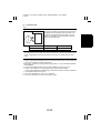
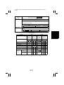
Safety Precautions for Inspection and Service
When performing inspection and service procedures, observe the following precautions to
prevent accidents and ensure utmost safety.
✽ Depending on the model, some of the precautions given in the following do not apply.
Different markings are used to denote specific meanings as detailed below.
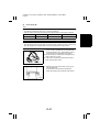
WARNING
CAUTION
Indicates a potentially hazardous situation which, if not avoided,
could result in death or serious injury.
Indicates a potentially hazardous situation which, if not avoided,
may result in minor or moderate injury. It may also be used to
alert against unsafe practices.
The following graphic symbols are used to give instructions that need to be observed.
Used to call the service technician’s attention to what is graphically represented
inside the marking (including a warning).
Used to prohibit the service technician’s from doing what is graphically represented inside the marking.
Used to instruct the service technician’s to do what is graphically represented
inside the marking.
WARNING
1. Always observe precautions.
• Parts requiring special attention in this product will include a label containing the
mark shown on the left plus precautionary notes. Be sure to observe the precautions.
• Be sure to observe the “Safety Information” given in the Operator’s Manual.
2. Before starting the procedures, be sure to unplug the power cord.
• This product contains a high-voltage unit and a circuit with a large current
capacity that may cause an electric shock or burn.
• The product also contains parts that can jerk suddenly and cause injury.
• If this product uses a laser, laser beam leakage may cause eye damage or
blindness.
3. Use the specified parts.
• For replacement parts, always use the genuine parts specified in the manufacturer’s parts manual. Installing a wrong or unauthorized part could cause dielectric breakdown, overload, or undermine safety devices resulting in possible
electric shock or fire.
• Replace a blown electrical fuse or thermal fuse with its corresponding genuine
part specified in the manufacturer’s parts manual. Installing a fuse of a different
make or rating could lead to a possible fire. If a thermal fuse blows frequently,
the temperature control system may have a problem and action must be taken
to eliminate the cause of the problem.
P-1
FrameMaker Ver.5.5E(PC) PL/PS Standard Document Ver.01
00.09.13
4. Handle the power cord with care and never use a multiple outlet.
• Do not break, crush or otherwise damage the power cord. Placing a heavy
object on the power cord, or pulling or bending it may damage it, resulting in a
possible fire or electric shock.
• Do not use a multiple outlet to which any other appliance or machine is connected.
• Be sure the power outlet meets or exceeds the specified capacity.
5. Be careful with the high-voltage parts.
• A part marked with the symbol shown on the left carries a high voltage. Touching it could result in an electric shock or burn. Be sure to unplug the power cord
before servicing this part or the parts near it.
6. Do not work with wet hands.
• Do not unplug or plug in the power cord, or perform any kind of service or
inspection with wet hands. Doing so could result in an electric shock.
7. Do not touch a high-temperature part.
• A part marked with the symbol shown on the left and other parts such as the
exposure lamp and fusing roller can be very hot while the machine is energized.
Touching them may result in a burn.
• Wait until these parts have cooled down before replacing them or any surrounding parts.
8. Maintain a grounded connection at all times. (This item may not apply in the USA.)
• Be sure to connect the ground wire to the ground terminal even when performing an inspection or repair. Without proper grounding, electrical leakage could
result in an electric shock or fire.
• Never connect the ground wire to a gas pipe, water pipe, telephone ground wire,
or a lightning conductor.
9. Do not remodel the product.
• Modifying this product in a manner not authorized by the manufacturer may
result in a fire or electric shock. If this product uses a laser, laser beam leakage
may cause eye damage or blindness.
10. Restore all parts and harnesses to their original positions.
• To promote safety and prevent product damage, make sure the harnesses are
returned to their original positions and properly secured in their clamps and saddles in order to avoid hot parts, high-voltage parts, sharp edges, or being
crushed.
• To promote safety, make sure that all tubing and other insulating materials are
returned to their original positions. Make sure that floating components mounted
on the circuit boards are at their correct distance and position off the boards.
P-2
FrameMaker Ver.5.5E(PC) PL/PS Standard Document Ver.01
00.09.13
CAUTION
1. Precautions for Service Jobs
• A toothed washer and spring washer, if used originally, must be reinstalled.
Omitting them may result in contact failure which could cause an electric shock
or fire.
• When reassembling parts, make sure that the correct screws (size, type) are
used in the correct places. Using the wrong screw could lead to stripped
threads, poorly secured parts, poor insulating or grounding, and result in a malfunction, electric shock or injury.
• Take great care to avoid personal injury from possible burrs and sharp edges on
the parts, frames and chassis of the product.
• When moving the product or removing an option, use care not to injure your
back or allow your hands to be caught in mechanisms.
2. Precautions for Servicing with Covers and Parts Removed
• Wherever feasible, keep all parts and covers mounted when energizing the
product.
• If energizing the product with a cover removed is absolutely unavoidable, do not
touch any exposed live parts and use care not to allow your clothing to be
caught in the moving parts. Never leave a product in this condition unattended.
• Never place disassembled parts or a container of liquid on the product. Parts
falling into, or the liquid spilling inside, the mechanism could result in an electric
shock or fire.
• Never use a flammable spray near the product. This could result in a fire.
• Make sure the power cord is unplugged before removing or installing circuit
boards or plugging in or unplugging connectors.
• Always use the interlock switch actuating jig to actuate an interlock switch when
a cover is opened or removed. The use of folded paper or some other object
may damage the interlock switch mechanism, possibly resulting in an electric
shock, injury or blindness.
3. Precautions for the Working Environment
• The product must be placed on a flat, level surface that is stable and secure.
• Never place this product or its parts on an unsteady or tilting workbench when
servicing.
• Provide good ventilation at regular intervals if a service job must be done in a
confined space for a long period of time.
• Avoid dusty locations and places exposed to oil or steam.
• Avoid working positions that may block the ventilation ports of the product.
4. Precautions for Handling Batteries (Lithium, Nickel-Cadmium, etc.)
• Replace a rundown battery with the same type as specified in the manufacturer’s parts manual.
• Before installing a new battery, make sure of the correct polarity of the installation or the battery could burst.
• Dispose of used batteries according to the local regulations. Never dispose of
them at the user’s premises or attempt to try to discharge one.
P-3
FrameMaker Ver.5.5E(PC) PL/PS Standard Document Ver.01
00.09.13
5. Precautions for the Laser Beam (Only for Products Employing a Laser)
• Removing the cover marked with the following caution label could lead to possible exposure to the laser beam, resulting in eye damage or blindness. Be sure
to unplug the power cord before removing this cover.
• If removing this cover while the power is ON is unavoidable, be sure to wear
protective laser goggles that meet specifications.
• Make sure that no one enters the room when the machine is in this condition.
• When handling the laser unit, observe the “Precautions for Handling Laser
Equipment.”
1167P001AA
DANGER
Invisible laser radiation when open.
AVOID
DIRECT
TO BEAM
EXPOSURE
0947-7127-01
1144D270AA
Other Precautions
• When handling circuit boards, observe the “HANDLING of PWBs”.
• The PC Drum is a very delicate component. Observe the precautions given in “HANDLING OF THE PC DRUM” because mishandling may result in serious image problems.
• Note that replacement of a circuit board may call for readjustments or resetting of particular items, or software installation.
P-4
FrameMaker Ver.5.5E(PC) PL/PS Standard Document Ver.01
00.09.13
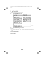
Used Batteries Precautions
ALL Areas
CAUTION
Danger of explosion if battery is incorrectly replaced.
Replace only with the same or equivalent type recommended by the manufacturer.
Dispose of used batteries according to the manufacturer’s instructions.
Germany
VORSICHT!
Explosionsgefahr bei unsachgemäßem Austausch der Batterie.
Ersatz nur durch denselben oder einen vom Hersteller empfohlenen ähnlichen Typ.
Entsorgung gebrauchter batterien nach Angaben des Herstellers.
France
ATTENTION
Ily a danger d’explosion s’ily a remplacement incorrec de la batterie.
Remplacer uniquement avec une batterie du meme type ou d’un type équivalent recommande par le constructueur.
Mettre au rebut les batteries usageés conformément aux instructions du fabricant.
Denmark
ADVARSEL!
Lithiumbatteri - Eksplosionsfare ved fejlagtig håndtering Udskiftning må kun ske med batteri af samme fabrikat og type.
Levér det brugte batteri tilbage til leverandøren.
Norway
ADVARSEL
Eksplosjonsfare ved feilaktig skifte av batteri.
Benytt samme batteritype eller en tilsvarende type anbefalt av apparatfabrikanten.
Brukte batterier kasseres i henhold til fabrikantens instruksjoner.
Sweden
VARNING
Explosionsfara vid felaktigt batteribyte.
Använd samma batterityp eller en ekvivalent typ som rekommenderas av apparattillverkaren.
Kassera använt batteri enligt fabrikantens instruktion.
Finland
VAROlTUS
Paristo voi räjähtää, los se on virheellisesti asennettu.
Vaihda paristo ainoastaan laitevalmistajan suosittelemaan tyyppiin. Hävitä Käytetty paristo
valmistajan ohjeiden mukaisesti.
P-5
FrameMaker Ver.5.5E(PC) PL/PS Standard Document Ver.01
00.09.13
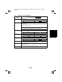
Precautions for Service
When performing inspection and service procedures, observe the following precautions to
prevent mishandling of the machine and its parts.
✽ Depending on the model, some of the precautions given in the following do not apply.
Precautions Before Service
• When the user is using a word processor or personal computer from a wall outlet of the
same line, take necessary steps to prevent the circuit breaker from opening due to overloads.
• Never disturb the LAN by breaking or making a network connection, altering termination,
installing or removing networking hardware or software, or shutting down networked
devices without the knowledge and express permission of the network administrator or
the shop supervisor.
How to Use this Book
1. DIS/REASSEMBLY, ADJUSTMENT
• To reassemble the product, reverse the order of disassembly unless otherwise specified.
2. TROUBLESHOOTING
• If a component on a PWB or any other functional unit including a motor is defective, the
text only instructs you to replace the whole PWB or functional unit and does not give
troubleshooting procedures applicable within the defective unit.
• All troubleshooting procedures contained herein assume that there are no breaks in the
harnesses and cords and all connectors are plugged into the right positions.
• The procedures preclude possible malfunctions due to noise and other external causes.
Precautions for Service
• Check the area surrounding the service site for any signs of damage, wear or need of
repair.
• Keep all disassembled parts in good order and keep tools under control so that none will
be lost or damaged.
• After completing a service job, perform a safety check. Make sure that all parts, wiring
and screws are returned to their original positions.
• Do not pull out the toner hopper while the toner bottle is turning. This could result in a
damaged motor or locking mechanism.
• If the product is to be run with the front door open, make sure that the toner hopper is in
the locked position.
• Do not use an air gun or vacuum cleaner for cleaning the ATDC Sensor and other sensors, as they can cause electrostatic destruction. Use a blower brush and cloth. If a unit
containing these sensors is to be cleaned, first remove the sensors from the unit.
P-6
FrameMaker Ver.5.5E(PC) PL/PS Standard Document Ver.01
00.09.13
Precautions for Dis/Reassembly
• Be sure to unplug the copier from the outlet before attempting to service the copier.
• The basic rule is not to operate the copier anytime during disassembly. If it is absolutely
necessary to run the copier with its covers removed, use care not to allow your clothing
to be caught in revolving parts such as the timing belt and gears.
• Before attempting to replace parts and unplug connectors, make sure that the power
cord of the copier has been unplugged from the wall outlet.
• Be sure to use the Interlock Switch Actuating Jig whenever it is necessary to actuate the
Interlock Switch with the covers left open or removed.
• While the product is energized, do not unplug or plug connectors into the circuit boards
or harnesses.
• Never use flammable sprays near the copier.
• A used battery should be disposed of according to the local regulations and never be discarded casually or left unattended at the user’s premises.
• When reassembling parts, make sure that the correct screws (size, type) and toothed
washer are used in the correct places.
• If it becomes necessary to replace the thermal fuse or any other fuse mounted on a
board, be sure to use one of the rating marked on the blown fuse. Always note the rating
marked on the fuse, as the rating and mounting site or number used are subject to
change without notice.
Precautions for Circuit Inspection
• Never create a closed circuit across connector pins except those specified in the text and
on the printed circuit.
• When creating a closed circuit and measuring a voltage across connector pins specified
in the text, be sure to use the GND wire.
P-7
FrameMaker Ver.5.5E(PC) PL/PS Standard Document Ver.01
00.09.13
Handling of PWBs
1. During Transportation/Storage:
• During transportation or when in storage, new P.W. Boards must not be indiscriminately
removed from their protective conductive bags.
• Do not store or place P.W. Boards in a location exposed to direct sunlight and high temperature.
• When it becomes absolutely necessary to remove a Board from its conductive bag or
case, always place it on its conductive mat in an area as free as possible from static electricity.
• Do not touch the pins of the ICs with your bare hands.
• Protect the PWBs from any external force so that they are not bent or damaged.
2. During Inspection/Replacement:
• Avoid checking the IC directly with a multimeter; use connectors on the Board.
• Never create a closed circuit across IC pins with a metal tool.
• Before unplugging connectors from the P.W. Boards, make sure that the power cord has
been unplugged from the outlet.
• When removing a Board from its conductive bag or conductive case, do not touch the
pins of the ICs or the printed pattern. Place it in position by holding only the edges of the
Board.
• When touching the PWB, wear a wrist strap and connect its cord to a securely grounded
place whenever possible. If you cannot wear a wrist strap, touch a metal part to discharge static electricity before touching the PWB.
• Note that replacement of a PWB may call for readjustments or resetting of particular
items.
Handling of Other Parts
• The magnet roller generates a strong magnetic field. Do not bring it near a watch, floppy
disk, magnetic card, or CRT tube.
P-8
FrameMaker Ver.5.5E(PC) PL/PS Standard Document Ver.01
00.09.13
Handling of the PC Drum
✽ Only for Products Not Employing an Imaging Cartridge.
1. During Transportation/Storage:
• Use the specified carton whenever moving or storing the PC Drum.
• The storage temperature is in the range between –20°C and +40°C.
• In summer, avoid leaving the PC Drum in a car for a long time.
2. Handling:
• Ensure that the correct PC Drum is used.
• Whenever the PC Drum has been removed from the copier, store it in its carton or protect it with a Drum Cloth.
• The PC Drum exhibits greatest light fatigue after being exposed to strong light over an
extended period of time. Never, therefore, expose it to direct sunlight.
• Use care not to contaminate the surface of the PC Drum with oil-base solvent, fingerprints, and other foreign matter.
• Do not scratch the surface of the PC Drum.
• Do not apply chemicals to the surface of the PC Drum.
• Do not attempt to wipe clean the surface of the PC Drum.
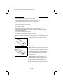
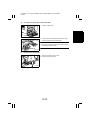
If, however, the surface is contaminated with fingerprints, clean it using the following procedure.
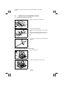
1. Place the PC Drum into one half of its carton.
1076D001
1076D002
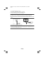
2. Gently wipe the residual toner off the surface of the
PC Drum with a dry, Dust-Free Cotton Pad.
A. Turn the PC Drum so that the area of its surface on
which the line of toner left by the Cleaning Blade is
present is facing straight up. Wipe the surface in
one continuous movement from the rear edge of
the PC Drum to the front edge and off the surface
of the PC Drum.
B. Turn the PC Drum slightly and wipe the newly
exposed surface area with a CLEAN face of the
Dust-Free Cotton Pad. Repeat this procedure until
the entire surface of the PC Drum has been thoroughly cleaned.
✽ At this time, always use a CLEAN face of the dry
Dust-Free Cotton Pad until no toner is evident on the
face of the Pad after wiping.
P-9
FrameMaker Ver.5.5E(PC) PL/PS Standard Document Ver.01
00.09.13
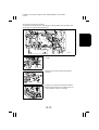
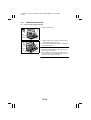
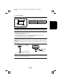
3. Soak a small amount of either ethyl alcohol or isopropyl alcohol into a clean, unused Dust-Free Cotton Pad which has been folded over into quarters.
Now, wipe the surface of the PC Drum in one continuous movement from its rear edge to its front
edge and off its surface one to two times.
✽ Never move the Pad back and forth.
1076D003
4. Using the SAME face of the Pad, repeat the procedure explained in the latter half of step 3 until the
entire surface of the PC Drum has been wiped.
Always OVERLAP the areas when wiping. Two
complete turns of the PC Drum would be appropriate for cleaning.
1076D004
NOTES
• Even when the PC Drum is only locally dirtied, wipe the entire surface.
• Do not expose the PC Drum to direct sunlight. Clean it as quickly as possible even under
interior illumination.
• If dirt remains after cleaning, repeat the entire procedure from the beginning one more
time.
Handling of the Imaging Cartridge
✽ Only for Products Employing an Imaging Cartridge.
1. During Transportation/Storage:
• The storage temperature is in the range between –20°C and +40°C.
• In summer, avoid leaving the Imaging Cartridge in a car for a long time.
2. Handling:
• Store the Imaging Cartridge in a place that is not exposed to direct sunlight.
3. Precautionary Information on the PC Drum Inside the Imaging Cartridge:
• Use care not to contaminate the surface of the PC Drum with oil-base solvent, fingerprints, and other foreign matter.
• Do not scratch the surface of the PC Drum.
• Do not attempt to wipe clean the surface of the PC Drum.
P-10
FrameMaker Ver.5.5(PC) Di200/Di251/Di351
01.02.02
INDEX (FIELD SERVICE)
DIS/REASSEMBLY,
ADJUSTMENT
SWITCHES ON PWBs,
TECH. REP. SETTINGS
TROUBLESHOOTING
!"#"
$
%%$
#"!"%# &
&
#""%#%!#!"' &
&
!"%#%(##)"(*!#" &
&
"+((!"#%""%!( &
,-./,012 &
3422/525.5,
&
%/6012
&
&
&
%%%#7"%"8
#""%##%%!
&
&
%%!"%#%"("
%%#"
&9
&
"'&!"#%""%#
&:
5;45</6-"&!-544
&:
5;45</6-=2/5;22> &:
4..?5</6-=2/5;22> &$
@ 5;45</6>.065.A.?544).,>.065.A.?
544=26.? &$
4..?5</6,5;
&
&@
%""%# &
5;45</6(!./ &
5;45</6!./ &@
4..?5</60..42=26.?2 &@
@ 4..?5</652 &
4..?5</6.2
&
9 4..?5</6%?.4)422
&
B 5;45</60.. &9
: 5;45</60..;342 &B
$ +.,.?5</60..;342
&:
&
)"#"%#
&
5;45</6?".2<54422> &
4..?5</65340/5,
&
4..?5</6&?".2<)=,4/ &
@ 5;45</6%A5.4/
&
&9
%#)"%# &@
5;45</6?.?/,?
&@
&B
!#)"%# &
5;45</6=2.?!./ &
5;45</6=2.?544(/-?6/=2.?544
.,</=2.?544 &9
5;/6=2.?544"62/5=2.?544(/
-=2.,=2.?544"652// &$
!"#"
&
&
!"#" )#"%%!
&
&
!"#"*!#"" &
&
!"#""" &
!"#"
$
&@
!"#"%##%"%"#)""#%# &
&
") !"#"
&
"5=06.4,C
&
%?.4A/0/.?.25,C=2/./B& &@
55-,C=2/./
&
@ ,?2
&9
?2//5../ &$
9 ?2//5../ &@
B ?2//5. &@
: D55,C=2/ &@B
$ &2=+,/6 &
55./2 &
&9
%!&%"%##)%"(####
%) &
@
#%! &
@&
#""%#%"('%!#"%'"%"%# &
@&
%!#"#)"(% &9
@&
!""#!" &B
FrameMaker Ver.5.5E(PC) Di200/Di251/Di351 DIS/REASSEMBLY, ADJUSTMENT
01.02.09
DIS/REASSEMBLY,
ADJUSTMENT
10230
!"#"
$
%$
!"#$
!%
*),2/((
@-0*)"
/4*00(7!,-!
✽
✽
✽
>✽
A
A
A
*),2/((
"'/)--"
?
%
&
'(✽)**$$**+*,
!(
-.'// 0-
.(!(
-
& "'()*)+,-')./0))./,+*.-/()'1,2-'3/((/4,2)0.3.-/,)
✽%.0./0
=
0/4
6*-0*-41(,2-'
%.0./0
8
8
>>%>$,
>>%>$,
✽5!
,+,+6,(7
& 8',()0/-.-12/22()-/9*)+)(.-/,)4-'(,)./,3/,2-/-'
9/1)0.3.-/,)
& 8',+)))9(7:/9,+)-/903/+,-'()90-')*.')4',
4/,2/*,+-'0,-'+,+*9)*3)--/-*,-'./06
& 3-':/9;*)-'--'./09(3-6#-/337/*4-.',+,2,+4()
0/-.-12/22()
& '2'(73(.-1-//(.,9+,2/*)3-)9/*2'-,-/-'()90-'
!)
*-/)-.4',',+(,2-//()/,-'*)<)0))
& "'0,-'+),/-,-,9(,-'3(+
-)-/90(.+),))9(7
,.(*+,2-'./,-/(9/+
#1-'3/--0--//1-'()+/+/+:*)-
-)/,-'./,-/(9/+
%
!"#"
$
!"
# $"
$%
&$
$%
&'()&*+,**-.,)-))-**/01.2()*+2&+(.(01/&32*)&.*))
)-4+).1(&*-00(.)/&32*)&*)..5&()-40&
4)/+.*2(5.&/01(+**1).&***/0(1.4)-***/0*(&2()*
&***/011/&.('.5&&)-))-+.(&).(*'))(6**/01)
#.)0*.)-),-(),...*+,*2*&.()-')(72*).(.(01.('%
*())5*+,1/&,)-&'()
'
( )&
""$ "
$
$ .(.))2()-5/0**).*.(/.&*4.,-+-(.&32*)(6(*)2+).(*65((
8 !"#"
9
* !"
0)-.26-(.)&,)-&'())-4.00.,(6*+,*2*)(.)/0..*(&.%
&32*)&
;*+,*.()-<!().5
:
%
!"#"
$
010
22
34
$
A
?
>
D
D
>
A
$
?
?
?
?
D
>
A
$
??
%
!"#"
$
#/
-#
/1(/.+*
62,(E())
/1,/
>
→/1-4/'/(+,29.-)
2'-/1
/1-4/).4)-'-).*-'2'-/1
!00
,)+/1
!,'///,-9,+/1-'!00,)+/1
?
/4
,)+/1
/1,/
→/1,/
→/1-'/+
→/1
-'8%/+))7
→60,-',*(70))"7
→60,-'=-
/1/3,/
→/1-').4)-'-).*-',)+/1
✽ //1(/3-'/+))7,+8%/+))7))-0)
-'/*2'/3F/1(/3-'@!,-F/3F%
6""6#
F
☞ %
*),2!,-
D
/,-,)+
/1
/1,/
→/1,/
→/1-4/).4)-'-).*-'
/,-,)+/1
>
"/,/--(
/1
60,-'"/,/--(/1
→!,'//-'+/4()-3/*0(.)/3-'
"/,/--(/1,+/1-'./1
A
*0(=!,-✽
/1,/
A
→/1-4/./,,.-/)
→/1-4/).4)-'-
).*-'*0(=!,-
$
+/1
G
,*(70))
"7
/1,/
A
→!,0(*2/,./,,.-/
→/1-').4)-'-
).*-',*(70))"7
=+0H
))--+
/1✽
60,-'+/1
→(+-'+/1-/-'3/,-,+--')
-0*((-')+/*-/3-'3
/,-/1
(+/*-,/
→/1-').4)-'-).*-'/,-/1
*(-*0/)
))--
(+/*--'*(-*0/)))--
→*)',2-'-9/,-'2'-(0*((
/*--'.))--
?
=+0H
))--✽
(+/*--'=+0H))--
→*)',2-'-9)/,9/-'-'
2'-,+(3-()0*((/*--'.))--
!00/1
/1-4/).4)-'-).*-'!00/1
D
/,-/(,(
/1,/
→/1,/
>
→/1,/
D
→/1,/
→
/131).4)-'-).*-'/,-/(,(
>
!00/,-
/1
/1,/
→/1,/
>
→/1,/
D
→/1)=
).4)-'-).*-'!00/,-/1
A
3-/,-!00
/1
/1,/
>
→/1-4/).4)-'-).*-'3-/,-!00
/1
$
/,-@/(+,2
.-
/1-4/).4.0)
→/1-4/).4)-'-).*-'/,-@/(+%
,2.-
!003-/1
/1,/
>
→/1-4/).4)-'-).*-'!003-/1
3-@,2/1
/1/,).4-'-).*)-'@,2/1
@/(+,2
.-
/1,/)
$,+
→/1-4/).4)-'-).*-'@/(+%
,2.-
2'-@,2
/1
/1/,).4-'-).*)-'@,2/1
?
62,(/1
*((-'62,(/1)-2'-*04+
3-/1
/1-4/).4)-'-).*-'3-/1
D
3-
/1
/1/,).4-'-).*-'3-/1
>
=-/4/1
/1-'*),2!,-
→/1,/
?
→!,'//-'-4/-9)/3-'
=-/4/1,+/1-'./1
A
3-/1
/13/*).4)-'-).*-'3-/1
%?
!"#"
$
#/
-#
$
=+0H
))--
/,,.-//1
✽
!,'///,-9,+/1-'=+0H))--/,,.-/
/1
/1(/.+*
/,,.-//1
!,'///,-9,+/1-'/,,.-//1
@,))/1
/1/,).4-'-).*)-'@,))/1
/4
/1
/1,/
→/1,/
→/1,/
A
→/1-'
).4)-'-).*-'/4/1
!00
/1
/1,/
→60,,/
>
→/1-').4)-'-).*-'
!00/1
?
!00
/1
/1-4/).4)-'-).*-'!00/1
✽5-,++/,-'%.0./0
✽5-,++/,-'%.0./0
%
!"#"
$
& 8',/1,2..*-9/+//-'(.-.(./0/,,-3-/B!"6#
6@##E"@8)C./,-,+,8"@6#8),+3/((/4-'./%
)0/,+,2/1(0/.+*)
& "'/1(0/.+*)21,,-'3/((/4,2/--'/1(/3./,,.-/),+
).4)).*,2-'..*-9/+)*00/-/..*-9/+
& 8'-)9)/(*-(7,.))7-/-/*.'-'),+/-'(.-.(./0/,,-)/,-'
9/+9)*-/2/*,+7/*9/+7
8%
8%
8%#
8%
#
!#
!
8%
8%
8%
8%
8%@
!
!
%D
?
!"#"
$
+1,*
-#
,2*,/34
5%
6-,3
,2-.!00,2
→,2-.!00,2
→,2-..*3,7
→,2-.,366+
→
5%
✽ ,3-*666-06-.,48.,9:,2*,9-.;
!)-:,9:%
(""(#
:
5%
)*,3
,2-.,)-,2
→,2-.,)-;,*3)8/-
→
,2-.9-,)-!00,2
→,2-.!00,)-
,2
→,2676/<6)3-.,)-,*)*
→5%
5%;
,41*3
-/-)8,3✽
*3,4--.4*-40,666--
→,2,)6/<)3-.
5%;,4)-)8/-
→5%;
5%
0=
-/-)8,3
,2-.;)66,2
→,2-.,2
→!).,,
-<,-16)3,2-.5,2
→5%
5%
(,3
,2-.!00,2
→,2-.!00,2
→,2-..*3,7
→,25%)35%#--.
6-
→5%
5%#
#-<,(,3
,2-.!00,2
→,2-.!00,2
→,2-..*3,7
→,25%)35%#--.
6-
→5%#
5%
46
66-
,3
,2-.46)8!)-
→5%
5%
%")69>43*-
66-
,3
(0)-.3,2)3,2-.-/*")60,-!)-
→
5%
5%
%")69>43*-
66-
,3
(0)-.3,2
→,2-.
→,2,)6/<)3
-.5,2
→5%
,3
,2-.9-,2
→,2-.6/<6)3-.
;)66,2
→
,3
,2-.!00,2
→,2-.!00,2
→,2-..*3,7
→,25%)35%#
→ ✽ ,3-*666-06-.,48.$,9:,2*,9-.;!)-:
,9:%
(""(#
:
,3
☞ %?
#
)2-,3
,2-.(8)*>*66
→#
!
,<400*+!)-
,2-.!00,2
→,2-.,)-,2
→,2
-.9-,2
→,2-.)9,/)-/-
→,2
-.6/<6)3-.!,4)-)8/-66+
→!
!
;8.,*-8!)-
(0)-.3,2
→,2-.
,2-<,6/<6)3
-.;8.,*-8!)-,2
→!
!
)2-,3
,2-.,)-,2
→,2-.!00,)-,2
→
,2-.,)-;,*3)8/-
→,2-.9-,)-!00
,2
→,2676/<6)3-.,)-,*)*
→!
!#
",4/.)*
,2-.,)-,2
→,2-.!00,)-,2
→
,2-.,)-;,*3)8/-
→,2-.9-,)-!00
,2
→,2676/<6)3-.,)-,*)*
→!#
✽'()*+,)-.%/0/,0
%&
!"#"
$
!
*3,4--.4*-40,666--
?&
,/-.09-)8*-
)0,99,)%/*0,9-.0"%!0,**
66+
?
*3-.0"%!0,**66+-,-.
6,-.--/)104**3,99-.146.)8--.
9,)-
?@
)0,99,)%/*0)3,2-.0"%
!0,**
?@
"#$ $$%
(0)-.3,2
?$
,2-.046-,266+
?
%@
!"#"
$
-"$#$9+,%/"!'*)%5+6'))8
/1-'0*)-/1))7
!),29*)'4')+*)-,++-/33-'0
*)-/1))7
?
:
5+6"-+,%/8$&/'+$#;#$9+--'"'"$ 8$&/'+$#;#$9+--'*)/#$9
60,-'+/1
?$
,0/33-4/-,,2,2)-70,+-'*00
,+(/47,.'/,H,2/((2)
?
/1/,).4,+-'2/*,+0(-
?
E/*,+(-
*)',2)
%
1//
'
/
(
.
/
??
%$
!"#"
$
?
/1/,)0,2,+-'*00,+(/4
7,.'/,H,2/((9*)',2)
%
1/.
/'
/.
/
?
,0/33/,-,,2,2-70*,0(*2/,
./,,.-/,+/1-'7,.'/,H,2(*-.'
D
/1/,4)',+-4/414)')
?D
>
!,'///,)0,2),0/33-4/-,,2,2)
-70,+/1-'*00,+(/47,.'/%
,H,2/((9*)',2)
%
1/.
/'
/.
/
?>
<
-"$#$9+,%/# +6'
!),2)/3-.(/-'+0,+4-'(./'/(40
-'+/1
?A
%
!"#"
$
:
5+6"-+,%/$#%
%$
!2
(
.3'
4!2
56764.3
!2
1!2.'(/3
8
6/64/)#,)!,4/)04,
/1-'!00/1/,-/13-/1!00/1/4
/1,+3-@,2/1
/1).4)?/,+-''(+/1
?
%
&
.(
/
.'/
&
(-
( 9
(
#
!,0(*23/*./,,.-/)/3-'/+
?
/1-'',))3/-4/./+.(0),+
/,4,2)++(
?>
?>
!,0(*2/,./,,.-//3-''//*0',)),+
/1-'',))3//,4,2)++(
D
/1/,).4,+-'./,,.-//*,-,2
9.-
?
>
!,0(*2-'./,,.-/)3/-'./,,.-/
/*,-,29.-
??
%
!"#"
$
A
!,0(*2/,./,,.-/
$
/131).4),+/,8)*00/-
"','/(+,2-'/+))7--'
)(-4-'3,2/37/*(3-',+)-'((*)--/,/1-'))7
?A
%$
1/9$9-
(( )!
,
1/9$9-'(..'(#
// )!9#
,
1/9/9$9-
!19
/--
-
'- )!
,
"9
"9
?
%
!"#"
$
/1((./,,.-/)/38%
/1-'',))3/)=./+.(0))=4,2)++(),+-4/+2./1)
/1)=).4),+-'8%))7
?$
/1/,).4,+-'(=9(@,))
E*+
?
?
/131).4),+-',3/.,-
.-
?
!,0(*2/,./,,.-/3/-'/44-.'
D
/1-'',))3//,+2./13/*
4,2)++(),+-4/./+.(0)
?
%
!"#"
$
>
/1-').4),+-'/*,-,29.-
A
/13/*).4),+-'@!,-
?
5+6"-+,%/$#%
/1-'62,(E())
!,'//-'-9)/3-'./1,/+/3
,+,+/1-'./1
??
!,0(*2-4/./,,.-/)/3-'!,-
?
/1-4/).4),+-'!,-
?
%$
1/##-( )4##
,
1##.'(/3
8
:3
)04,
-"$#$9+,%/&"$$'"#-)1*)/#$9)
/1-'62,(E())
!),2)/3-.(/-'40.(,-'.,,()
,+*)',2)
?D
%?
!"#"
$
:
-"$#$9+,%/#''+')
/1-'62,(E())
80.(,-'/)4-')/3-.(/-'
D>>
<
-"$#$9+,%/$)
/1-'!,-
80.(,-',)4-')/3-.(/-'
D>A
=
-"$#$9+,%/'#9#$"--"))
80.(,-'62,(E())4-')/3-.(/-'
>
%
!"#"
$
>
5+6"-+,%/&"$$'
/1-'62,(E())
/1-'@/(+,2.-
/1-'.,,-/-'(/.-/,)'/4,,-'
((*)--/,
?>
?
/1/,).4,+*,0(*2-'./,,.-//3
-'=0/)*0
/1-'3(-.9(/3-'=0/)*0
?A
D
/1/,).4,+-'0=,2.-
?$
>
(+-'=0/)*0-/-'3/,-,+/1
-
/,??
A
/1-4/).4),+-'.,,
??
%D
!"#"
$
?
5+6"-+,%/&"$$''#6".-)
/1-'62,(E())
/1-'.,,
/1-'3-!00/1,+3-/1
?
!,'//-')0,2--',+/3-'.9(3/
-'3/,-'//,+/1-'.9(2*+
9( !,'//-')0,2--',+/3-'.9(3/
E*+
-''//
/,-
??
D
/1/,).4*,0(*2/,./,,.-/,+
/1-'62,(H-.-,2,)/
✽ 60-/,3/-',.')
??
>
/1-'./1
✽ )-0/3F/1(/3-'!,-F/3F%
6""6#
F
A
/13/*).4),+-',3/.,-
.-
???
$
,0/33/,-,,2,2-70,+/1
/,/*,-,2).43/-'3/,-0*((7,+
)(+-'0*((7-/-'
??
,0/33/,-,,2,2-70,+/1
/,/*,-,2).43/-'0*((7,+
)(+-'0*((7-/-'3/,-
/1-'.,,19('//,+3)-
??D
%>
!"#"
$
@
#$ #$9+,%/&"$$''#6".-)
*((7
*((7@
*((7
*((7
*((7
*((7E
*((7
*((7
??>
/,
/)-/,-'/*,+9+/3-'.9()(1-
-'(/.-/,)'/4,,-'((*)--/,
D>
8,+-''//,+/3-'.,,19(
-4/-*,)./*,-.(/.4)3/-')+-/
-'3/,-
9(/,@//,+
D>
9(/,
+,+
8,+-'9+,+/3-'.9(3/*-*,).(/.%
4)3/-'3/,--/-'
"',).*-'
.9(4-'-0
%
'
.
D>
%A
!"#"
$
?
(+-'0*((7-/-'3/,-,+3-/,-,,2
,2-70
*)',2-'0*((7-2'-(7*02,)--'-,,2
,2-70).*-'0*((74-'/,).4
??A
D
8,+-'3=+9+,+/3-'.9(/*,+0*(%
(7,+0*((7,+3--'3=+9+-0/)%
-/,9/*-
3/-'.,,(
0*((7
0*((7
??$
>
8,+-''//,+/3-'.9(/*,+0*((7
,+0*((7
0*((7
0*((7
?
A
,)-((-'.9(2*+3--''//,+/3-'
.9(,-/-'2//1,-'.9(2*+,+
'//-')0,2
9(E*+
?
$
/)-/,-'/*,+9+/3-'.9(9(.-
-'0/)-/,)'/4,,-'((*)--/,
D>
%$
!"#"
$
8,+-''//,+/3-'.9(-4/-*,)./*,%
-.(/.4)3/-'3/,--/-'
9(/,@//,+
D>?
9(/,
+,+
8,+-'9+,+/3-'.9(3/*-*,).(/.%
4)3/-'-/-'3/,-
"',).*-'
.9(4-'-0
%
'
.
D>
(+-'0*((7-/4+-',+3-/,-,%
,2,2-70
*)',2-'0*((7-2'-(7*02,)--'-,,2
,2-70).*-'0*((74-'/,).4
?
?
8,+-'3=+9+,+/3-'.9(/*,+0*(%
(7@,+0*((7E,+3--'3=+9+-
0/)-/,9/*-
3/-'.,,(
0*((7@
0*((7E
?
8,+-''//,+/3-'.9(/*,+0*((7
,+0*((7
0*((7
0*((7
?
%
!"#"
$
D
--''//,+/3-'.9(,-/-'2//1,
-'9(E*+,+'//-')0,2
9(E*+
?
>
(/33-'-03/-'0*((7)--'3/,-,+
A
//),/,).4-'-).*)-')0,2/*,-,29.-
!),29-,)/,22
0*((-'/*,-,29.-4-'3/./3±2
I0,2-')./,+-/,-2'-,
-'/*,-,2).4
/,-
?D
/,-
$
))-',++/)2-2'-(7*0
2,)--'3/,-,+()
3/-'
/.*)%/)-/,,2/3-'.,,,+,++
/)2*),2-'+1.9(+:*)-,2
).4)--'3/,-,+)/-'--')
.(,./3F
F
?
/*,--'.,,
,)-((-',3/.,-.-
,)-((-'./1
/*,--'62,(H-.-/,,)/
?
,)-((-'3-/1
,)-((-'62,(E()),+3-!00/1
D
3/-'/.*)%/)-/,,2/3-'.,,,+,++/)2
✽ F%D
6!%6"6##E6"@####6%
E
F
%
1#...
'(/
3
8#:3
)04,
%
!"#"
$
<
5+6"-+,%/5"9'"$),'+--'))8
60,-'+/1
?$
)-'2",)3E*+(-
?D
/1-'2",)3/(())7
%
0/&
4-(.
?>
-"$#$9+,%/+5.-&%'+ 60,-'+/1
?$
!),2)/3-.(/-'+0,+4-'(./'/(40
-'/9(.-/+
?A
%$
'
0/&4
1(/#.6'
/.-.
%
!"#"
$
-"$#$9+,%/'5"9'"$),'*# -"%
60,-'+/1
?$
!),2)/3-.(/-'+0,+4-'(./'/(40
-'%2",)3E*+(-
%
'
0/&4
?$
:
5+6"-+,%/;+$#-%'
/1-'/4/1
/1-'6H/,(-
?D
%
!"#"
$
=
5+6"-+,%/5"9#$9"'%'# 9
60,-'+/1
?$
@/(+,2/,-/-'2,',+())(+-'2%
,2-+20-/3-'47/*-
"',2)0-'',+(/,-/0/3-'.-+2,+
0*((-'.-+2/*-
?D
%
1/0//#/
(-
0/-!#
/-.
-./
%?
!"#"
$
>
5+6"-+,%/*)#$9$#%
60,-'+/1
?$
*)'-'(1,+/0,-'=-/1
!,0(*2-4/./,,.-/),-'
?D
?
(/)-'=-/1/1-4/).4),+
)(+/*--'*),2!,-
!,0(*2/,./,,.-/--'3/,-,+/1
-'*),2!,-
?D
%
!"#"
$
5+6"-+,%/*)#$9+--'"%'"5!2#9/%*)#$9+--'2"$ ,%*)
#$9+--'
/1-'*),2!,-
60,-'=-/1
/1-').4),+-'*),2/,-
/1
%
/#.
(
/
/
#/
(-
./
,+)/3(-
0,2
,26*-
.+.
8'*),2/,-/1
)/*,-+
8',+)/3(-0,2
/1+
?D?
?
/1/,./+'/(+,+-'',))
?D
/1-4/).4))=./+'/(+),+-'
',))
?D>
%D
!"#"
$
D
/1-'',))3/-'/1
>
/1-4/).4),+-'/1
A
/1/,).4,+-'(0'/(+,-'
?DA
$
/1/,).4,+-'(0'/(+--'
3/,-
"',)(+/*--'*),2/((@-
0
?D$
/1-'',))3/-'',))2*+,+
+2./1
/1/,).4/,)'/*(+).4,+-'
0=-/1))7
?DD
/1-').4)/*0(,2E))7,+
2
/1-').4),+-'1))7
?
!,'//-')0,2-/3-'))*
1))7
?>
/1-4/).4),+-'1))7
D
!,'//-')0,2-/3-'/,-))*
1))7
>
,0/33/,-,,2,2-70,+/1
-'+((1
?>
%>
!"#"
$
&
'(')*+',-.*/0).1+,*)2
3,.**4
$
'(')*/0')*+',-.*/0).1+
/'(
56
)7'88')1))2)2147).'(
1+')1**,(**4).9)2
56
)7'88')1))2)2147).'(
1+**,(**4).9)2
'(1+2+1,*)2'--
565
'(1+*/0*8*7)2).1+
-(
56
%$
56:
%&
!"#"
$
?
/1/,)'/*(+).4,+-'2
,0/33/,-,,2,2-70,+/1
-'2))72,+)0,2
?>>
%$
-
(/
/./
-('
.-/
?>A
D
,0/33/,-,,2,2,+/1/,
4)',+/,414)'
>
/1/,9,2.'--'3/,-,+
,+-',/1-'3-*),2/((
?>$
5+6%/*)#$9+--'/'5#)%+'2*)#$9+--'"'%'"5!*)2"$ *)#$9+--'/'5+)%"%
/1-'*),2!,-
/1-'./+'/(+
/1-4/).4,+-'@/(+))7
?A
?
/1/,).4,+-'*),2/(("'%
)-/
/1-4/).4),+-'*),2/((
@-0*)
D
/1-4/).4),+-'*),2/(("'%
/)--
?A
%$
!"#"
$
A
A
A
.,,/)2/)-/,,2 2)
D>A
A
+:*)-,--
;*,-)
+:*)-,-/,-
3
2
*-/-.((7
+:*)-+
/,-/(,(
☞ %
62,(H-.-,2,)/
+:*)-,->%
↑
↑
☞ %?
//0+:*)-,-
G
↑
☞ %
+,2
G
↑
"(,2
G
↑
"/*.',(+:
+2)
2'-3-
☞ %D
G
↑
2)--/,,-
%)++5J
%)++5J
↑
☞ %$
2)--/,,-
J
↑
☞ %?
↑
↑
☞ %?
↑
↑
J
↑
J
↑
%)*8+-'
G
↑
☞ %
//,-)
G
↑
☞ %
2)--/,
K//+:*)-
%
☞ %?>
!"#"
$
"/*.',(+:
*-/-.
+:*)-,-
62,(H
-.-,2,)/
+:*)-,-
*-/-.
+:*)-,-
//0+:*)-,-
+2
)
❍
❍
❍
G
❍
3
2
6/+
0(.,-
/+0(.,-
/7.(
'+/4-.,-/39//
'+/4/362,(.()
0)49,+)3+
-/,),0,-(+,2
+21/+/*,-
@!,-0(.,-
)-/+0(.,-
☞ %
❍
❍
☞ %?
☞ %
❍
+,2
>
"(,2
--,2,2
-/
A
2'-3-
--,2,2
-/
$
%)++5
J
%)++5
J
☞ %$
☞ %?
2)--/,
,-
K//
+:*)-
❍
--,2,2
-/
2)--/,
,-
2)-%
-/,
.,,19()
0(.,-,)-((-/,
'.-
.,,/1(
/9-
62,(H-.-,2,%
)/)0(.,-++-/,
+:*)-,-
--,2-)
!,-.,,0-)
0(.,-
A
/,-/(,(0(.,-
J
J
J
D
J
J
%)*8+-'
--,2,2
-/
//,-)
--,2,2
-/
/.*)%/)-/,,2/3
.,,,+,++
/)2
G
❍
☞ %D
☞ %?
☞ %?>
?
☞ %
❍
☞ %
❍
❍
☞ %
!)L)'/./+
%,0*-
❍
☞ %D
".'
0
/+
%,0*-
❍
☞ %
.*-7/+
%,0*-
❍
+:*)-/+
%,0*-
/*,-
☞ %$
❍
❍
❍
☞ %>
☞ %D
%$
9
#4./-/
9$94;<49
&/
(.3
1/
/3
.
%
!"#"
$
:
A
/1-'62,(E())
//),-'-4/).4)-'-).*-'.,,
/-/
!),29-,)/,220*((-'/-/
-/-'2'-4-'-,)/,/32J2,+-
-')--2'-,-'/*,-,2).4)
?A
%
&3
.(.
(
-/
%
!"#"
$
<
1A
+*&/"$- B
"7%/#)" B*)%5$%",%'#%/'+,%/,+--+(#$9!'+& *')/"6.$!',+'5 4
& /7(
& /,-/(,(0(.,& 6/+0(.,+:*)-,-/.+*
((-',-(/+-/-').,
/+-())8"@6#8)"@
""#E
"/*.'F"/*.',(+:
F
?
?
??
?D
?
B,-(C.,
"/*.'FMF/,).,)'/4,9/1
%$
'
-=>=
(.
/(.
?
"/*.'FMF/,).,)'/4,9/1
"/*.'FMF/,).,)'/4,9/1
D
"/*.'FMF/,).,?)'/4,9/1
%
!"#"
$
'#9#$"-#;%&%#$9$)+' B*)%5$%>
"7%/#)" B*)%5$%",%'"$8+,%/,+--+(#$9!'+& *')/"6.$!',+'5 4
& /7(
& 3*(-7/2,()H+-.-/,/..*)
& 0(.,-/3-'!,-,+.,,0-),.(*+,2-'=0/)*0
& 62,(H-.-,2,)/++-/,/0(.,& 6/+0(.,+:*)-,-/.+*
-.31)'-)/39(,/N>00/,
-'62,(E()),+(/4-'62,(/1
D>
?
D
((-'".'
0
/+-/-').,
"/*.'F*,.-/,F-/+)0(7-'*,.-/,,*
"/*.'F>%F
))-'--7-/*,-'62,(H-.-,2,)/+:*)-,-3*,.-/,
"*,6,+6#-'/44-.'
%
&'-
/(
./
/
/
?
%?
!"#"
$
++! B*)%5$%
C*#'5$%
+:*)-)/-'-./.-(//0)3/+93/-'7,.'/,H,2/(()4',00)3+
-'/*2'
+:*)-/+
--,2(*
//0+:*)-,-
%-/M
%
&3
.(-(/-
8
//'(
+:*)-,-/.+*
((-'".'
0
/+-/-').,
"/*.'F".'
0
'/.F,+F,-F,-'-/+
"/*.'F//0+:*)-,-F-/.((*0-'//0+:*)-,-3*,.-/,
?
(.--'00)/*.3/4'.'-'+:*)-,-)-/9+
))-'(7-/.(-'.*,-)--,21(*
D
,--',4)--,21(*3/-'%I7+
✽ !)-'..))/+7/F✽F-/.',2-'M/%)2,
%%#$9$)%'*&%#+$)
& ',2-')--,21(*),.))7*,-(-',/1-/,),-'/*,-/31/+
2(/,2-'(+,2+2)4+3+,2+/2%/)3+
!)-/.',2
-'M/%)2,
!)-/.(
)--,21(*
!)-/,-)--,21(*
?$A
!)-/.',2-'M/%)2,
--,2(*
?
>
"/*.'F#F-/1(+--')--,21(*
%
9
=65='-.
/ 0!
4@-
/
A
3/-'))-0)-/+:*)-3//-'00)/*.)
%
!"#"
$
:
9'")
O+,2P
C*#'5$%
--')4+-'/,-'(+,2+2/300
4+-',-',29-4,,+
A
+:*)-/+
--,2,2
+2)+,2
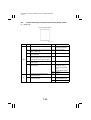
-/
1171D003AA
>
%
&3
.(!2.4/
)#<,)!,.
+:*)-,-/.+*
((-'".'
0
/+-/-').,
"/*.'F".'
0
'/.F,+F,-F,-'-/+
"/*.'F+2)F,+F+,2F,-'-/+-/.((*0-'+,2+2)
+:*)-,-3*,.-/,
?
))-'(7-/.(-'.*,-)--,21(*
,--',4)--,21(*3/-'%I7+
%%#$9$)%'*&%#+$)
"/-'+2)4+-'4+-')((+.)-')--,21(*
"/-'+2)4+-'4+-'2-,.)-')--,21(*
!)-/.(
)--,21(*
!)-/,-)--,21(*
--,2(*
?$$
D>D$
D
"/*.'F#F-/1(+--')--,21(*
%
9
=65=
/ 0!4'-
/
%D
!"#"
$
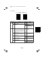
O"(,2P
C*#'5$%
A
--')4+-'/,-'-(,2+2/300
4+-',-',29-4,,+
+:*)-/+
--,2,2
+2)"(,2
-/
>?
1171D004AA
%
&3
.(!2.4/
)#<,)!,.
+:*)-,-/.+*
((-'".'
0
/+-/-').,
"/*.'F".'
0
'/.F,+F,-F,-'-/+
"/*.'F+2)F,+F"(,2F,-'-/+-/.((*0-'"(,2+2)
+:*)-,-3*,.-/,
?
))-'(7-/.(-'.*,-)--,21(*
,--',4)--,21(*3/-'%I7+
%%#$9$)%'*&%#+$)
"/-'+2)4+-'4+-')((+.)-')--,21(*
"/-'+2)4+-'4+-'2-,.)-')--,21(*
!)-/.(
)--,21(*
?$$
!)-/,-)--,21(*
--,2(*
D>D$
D
"/*.'F#F-/1(+--')--,21(*
%
9
=65=
/ 0!4'-
/
%>
!"#"
$
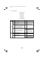
O2'-3-P
C*#'5$%
A
--')4+-'/,-'2'-,+(3-+2)/3
004+-',-',29-4,,+
+:*)-/+
--,2,2
+2)2'-3-
-/
A
1171D005AA
>
%
&3
.(!2.4/
)#,)!,.
+:*)-,-/.+*
((-'".'
0
/+-/-').,
"/*.'F".'
0
'/.F,+F,-F,-'-/+
"/*.'F+2)F,+F2'-3-F,-'-/+-/.((*0-'2'-3-+2)
+:*)-,-3*,.-/,
?
))-'(7-/.(-'.*,-)--,21(*
,--',4)--,21(*3/-'%I7+
%%#$9$)%'*&%#+$)
"/-'+2)4+-'4+-')((+.)-')--,21(*
"/-'+2)4+-'4+-'2-,.)-')--,21(*
!)-/.(
)--,21(*
?$$
--,2(*
!)-/,-)--,21(*
D>D$
D
"/*.'F#F-/1(+--')--,21(*
%
9
=65=
/ 0!4'-
/
%A
!"#"
$
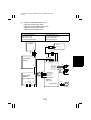
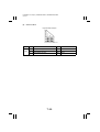
<
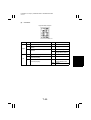
9#)%'"%#+$'#$%'
+:*)-)/-'-4+-'/,-'-)-0--,0/+*.+3(()4-',-'3/((/4,2,2
C*#'5$%
%+
X
TEST PRINT
X
TEST PRINT
%++
A
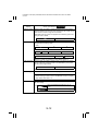
?DA
A
?DD
0.3.-/,
+:*)-/+
--,2,2
%++5J
%++5J
2)--/,
%?
-/M?
%
&3
.(!2.$
4/)#,)!,
4/),
)!,.
+:*)-,-/.+*
((-'+:*)-/+-/-').,
"/*.'F,-F,+F2)--/,F,-'-/+
%++5"/*.'F")-,-F,+)(.--'00)/*.3/4'.'-'+:*)-,-)-/
9+
%++5"/*.'F")-,-F,+)(.-F*0(=F
✽ --')--')-4))(.-+
?
))-'--7
✽ -)-0--,4((90/+*.+
%++5'.-/)34+-'/,-'-)-0--,-)-')0.3.-/,)
%++5'.-/)34+-'/,-')./,+)+/3-'%)++./07-)
-')0.3.-/,)
34+-'3(()/*-)+-')0.3+,203/-'3/(%
(/4,2)-0)3/+:*)-,-
D
"/*.'F#F-/.((-'2)--/,).,
>
(.--'00)/*.)(.-+,)-0
A
))-'(7-/.(-'.*,-)--,21(*
%$
!"#"
$
$
,--',4)--,21(*3/-'%I7+
✽ !)-'..))/+7/F✽F-/.',2-'M/%)2,
%%#$9$)%'*&%#+$)
34+-')4+-',)0.3.-/,)-')--,21(*)((-',-'.*,-/,
34+-'),/4-',)0.3.-/,)-')--,21(*2--',-'.*,-
/,
✽ 3),2(+:*)-,-0/.+*+/),/-)*..))3*((79,24+-',-/-')0.3+
,2-7,/-')--,21(*
!)-/.',2
-'M/%)2,
!)-/.(
)--,21(*
!)-/,-)--,21(*
?>
!)-/.',2-'M/%)2,
--,2(*
?
"/*.'F#F-/1(+--')--,21(*
%
9
=65=
/ 0!4'-
/
3/-'))-0)-/+:*)-3//-'00)/*.)
/&7#$9,+'# ,+'"&/"!'+*'&
& ,)-0-/*.'F")-,-F)(.--'00)/*.,+F*0(=F,+-',0))-'
--7
%?
!"#"
$
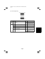
=
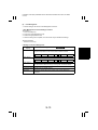
9#)%'"%#+$'#$%'
C*#'5$%
X
TEST PRINT
+:*)-)/-'-4+-'/,-'-)-0--,/*-0*-3(()
4-',-'3/((/4,2,2
A
?$>
0.3.-/,
J
+:*)-/+
--,2,2
2)--/,
✽%.0./05%D-/MD
%.0./05%$-/M$
✽5!
,+,+6,(7
%
&3
.(!2.4/
)#,)!,.
+:*)-,-/.+*
((-'+:*)-/+-/-').,
"/*.'F,-F,+F2)--/,F,-'-/+
"/*.'F")-,-F
?
))-'--7
✽ 04((93+3/-')-4,+-)-0--,4((90/+*.+
'.-/)34+-'/,-'-)-0--,-)-')0.3.-/,)
34+-'3(()/*-)+-')0.3+,203/-'3/((/4,2)-0)3/+:*)-,-
D
"/*.'F#F-/.((-'2)--/,).,
>
))-'(7-/.(-'.*,-)--,21(*
%?
!"#"
$
A
,--',4)--,21(*3/-'%I7+
✽ !)-'..))/+7/F✽F-/.',2-'M/%)2,
%%#$9$)%'*&%#+$)
34+-')4+-',)0.3.-/,)-')--,21(*)((-',-'.*,-/,
34+-'),/4-',)0.3.-/,)-')--,21(*2--',-'.*,-
/,
✽ 3),2(+:*)-,-0/.+*+/),/-)*..))3*((79,24+-',-/-')0.3+
,2-7,/-')--,21(*
!)-/.',2
-'M/%)2,
!)-/.(
)--,21(*
!)-/,-)--,21(*
--,2(*
?A
!)-/.',2-'M/%)2,
?
$
"/*.'F#F-/1(+--')--,21(*
%
9
=65=
/ 0!4'-
/
/&7#$9,+'"&/"!'+*'&
& %++5,)-0-/*.'F")-,-F)(.--'00)/*.-',0))-'--7
& %++5,)-0-/*.'F")-,-F)(.--'00)/*.,+F*0(=F-',0))
-'--7
%?
!"#"
$
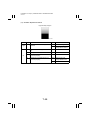
>
9#)%'"%#+$
OP
C*#'5$%
(.-'-)-0--,/*-0*-3--'+:*)-,-)/3
2)--/,,+,-'19,./%
0(-+/,-'62,(E()),+./07/3-
+:*)-)/-'-4+-'/,-'-)-0--,./073(()
4-',-'3/((/4,2,2
X
TEST PRINT
A
?$D
0.3.-/,
+:*)-/+
--,2,2
J
2)--/,
%>-/M>
%
&3
.(!2.3
4/)#,)!,#:3
)04,.
+:*)-,-/.+*
3--'+:*)-,-)/32)--/,,+,-,+/3K//+:*)-
'19,./0(-+0/+*.-)-0--,
✽ )-0)-'/*2'?/3F2)--/,,-F/3F%
"E
!"#"
F
(.-'-)-0--,0/+*.+/,-'62,(E()),+./07/3-
'.-/)34+-'/,-'-)-0--,./07-)-')0.3.-/,)
34+-'3(()/*-)+-')0.3+,203/-'))-0)-/-'+:*)-,-
?
((-'+:*)-/+-/-').,
"/*.'FFF2)--/,F,+FF,-'-/+
D
))-'(7-/.(-'.*,-)--,21(*
%?
!"#"
$
>
,--',4)--,21(*3/-'%I7+
✽ !)-'..))/+7/F✽F-/.',2-'M/%)2,
%%#$9$)%'*&%#+$)
34+-')4+-',)0.3.-/,)-')--,21(*)((-',-'.*,-/,
34+-'),/4-',)0.3.-/,)-')--,21(*2--',-'.*,-
/,
✽ 3),2(+:*)-,-0/.+*+/),/-)*..))3*((79,24+-',-/-')0.3+
,2-7,/-')--,21(*
!)-/.',2
-'M/%)2,
!)-/.(
)--,21(*
!)-/,-)--,21(*
--,2(*
?$
!)-/.',2-'M/%)2,
?
A
"/*.'F#F-/1(+--')--,21(*
%
9
=65=
/ 0!4'-
/
%??
!"#"
$
OP
C*#'5$%
X
TEST PRINT
(.-'-)-0--,/*-0*-3--'+:*)-,-)/3
2)--/,,+,-'19,./%
0(-+/,-'62,(E()),+./07/3-
+:*)-)/-'-4+-'/,-'-)-0--,./073(()
4-',-'3/((/4,2,2
A
?$>
0.3.-/,
+:*)-/+
--,2,2
J
2)--/,
%?-/M>
%
&3
.(!2.3
4/)#,)!,:3
)04,.
+:*)-,-/.+*
3--'+:*)-,-)/32)--/,,+,-,+/3K//+:*)-
'19,./0(-+0/+*.-)-0--,
✽ )-0)-'/*2'?/3F2)--/,,-F/3F%
"E
!"#"
F
(.-'-)-0--,0/+*.+/,-'62,(E()),+./07/3-
'.-/)34+-'/,-'-)-0--,./07-)-')0.3.-/,)
34+-'3(()/*-)+-')0.3+,203/-'))-0)-/-'+:*)-,-
?
((-'+:*)-/+-/-').,
"/*.'FFF2)--/,F,+FF,-'-/+
D
))-'(7-/.(-'.*,-)--,21(*
%?
!"#"
$
>
,--',4)--,21(*3/-'%I7+
✽ !)-'..))/+7/F✽F-/.',2-'M/%)2,
%%#$9$)%'*&%#+$)
34+-')4+-',)0.3.-/,)-')--,21(*)((-',-'.*,-/,
34+-'),/4-',)0.3.-/,)-')--,21(*2--',-'.*,-
/,
✽ 3),2(+:*)-,-0/.+*+/),/-)*..))3*((79,24+-',-/-')0.3+
,2-7,/-')--,21(*
!)-/.',2
-'M/%)2,
!)-/.(
)--,21(*
!)-/,-)--,21(*
?$
--,2(*
!)-/.',2-'M/%)2,
?
A
"/*.'F#F-/1(+--')--,21(*
%
9
=65=
/ 0!4'-
/
%?D
!"#"
$
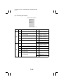
?
D++5 B*)%
OP
C*#'5$%
& "'+33,.)'/*(+94-',J
Q/3-'.-*((,2-'
& +:*)-)/-'--'3/((/4,2)0.3.-/,))-)3+4-').((,2-'/3
K//-/
0.3.-/,
+:*)-/+
--,2,2
*(()HN
J
K//+:*)-
$$-/
%
&3
.(#..
3
4/)#,)!,.
+:*)-,-/.+*
(.).(,0(((4-'-'62,(8+-'
.(,+./07
#/--'--').()
00,+.*(-/-'62,(,2-'.(
✽ !)-'3*(()HR
/+,+004-'
4+-'/3//
✽ 3-').()/30()-.,+-,)0,-0(.
9(,)'-/300/1-
D>
)*-'(,2-'/3-').(/,-'./07-/
3,+-'+33,.
3-'+33,.)/*-)+-')0.3.-/,
+:*)-973/((/4,2-'0/.+*)'/4,9(/4
??
%?>
!"#"
$
?
D
((-'+:*)-/+-/-').,
"/*.'FFFK//+:*)-F,+FF,-'-/+
))-'(7-/.(-'.*,-)--,21(*
,--',4)--,21(*3/-'%I7+
%%#$9$)%'*&%#+$)
3-').(/,-'./07)(/,2-',-'.-*().(+.)-')--,21(*
3-').(/,-'./07))'/--',-'.-*().(,.)-')--,21(*
✽ 3-')*,-+/),/-3((4-',-')0.3.-/,)-'/*2'/,)--,2-7,/-'
)--,2
!)-/.(
)--,21(*
!)-/,-)--,21(*
?
--,2(*
D>D$
>
"/*.'F#F-/1(+--')--,21(*
%
9
=65=
/ 0!4'-
/
%?A
!"#"
$
OP
C*#'5$%
& "'+33,.)'/*(+94-',J
Q/3-'.-*((,2-'
& +:*)-)/-'--'3/((/4,2)0.3.-/,))-)3+4-').((,2-'/3
K//-/
0.3.-/,
+:*)-/+
--,2,2
*(()HN
J
K//+:*)-
$$-/
%
&3
.(##.
3
4/)#,)!,.
+:*)-,-/.+*
(.).(,0(((4-'-'62,(,2-'
.(,+./07
✽ !)-'3*(()HN
/+,+/N>
00
✽ 3-').()/30()-.,+-,)0,-0(.
9(,)'-/300/1-
D>
)*-'(,2-'/3-').(/,-'./07-/
3,+-'+33,.
3-'+33,.)/*-)+-')0.3.-/,
+:*)-973/((/4,2-'0/.+*)'/4,9(/4
A?
%?$
!"#"
$
?
D
((-'+:*)-/+-/-').,
"/*.'FFFK//+:*)-F,+FF,-'-/+
))-'(7-/.(-'.*,-)--,21(*
,--',4)--,21(*3/-'%I7+
%%#$9$)%'*&%#+$)
3-').(/,-'./07)(/,2-',-'.-*().(+.)-')--,21(*
3-').(/,-'./07))'/--',-'.-*().(,.)-')--,21(*
✽ 3-')*,-+/),/-3((4-',-')0.3.-/,)-'/*2'/,)--,2-7,/-'
)--,2
!)-/.(
)--,21(*
!)-/,-)--,21(*
?
--,2(*
D>D$
>
"/*.'F#F-/1(+--')--,21(*
%
9
=65=
/ 0!4'-
/
%
!"#"
$
@
'")*'# %/
C*#'5$%
--')4+-'(/,2-'3/*+2)/3-'00
4+-',-',29-4,,+
▲
▲
A
▲
▲
+:*)-/+
--,2,2
%)*8+-'
-/
▲
▲
▲
▲
A
A
A
>D
%
&3
.((
;/
+:*)-,-/.+*
((-'".'
0
/+-/-').,
"/*.'F".'
0
'/.F
"/*.'F%)*8+-'F-/.((*0-'%)*8+-'+:*)-,-3*,.-/,
?
))-'(7-/.(-'.*,-)--,21(*
,--',4)--,21(*3/-'%I7+
%%#$9$)%'*&%#+$)
"/-')4+-'(/,2-'3/*+2)/3-'004+-')((+.)-'
)--,21(*
"/-')4+-'(/,2-'3/*+2)/3-'004+-'2-,.)-'
)--,21(*
!)-/.(
)--,21(*
!)-/,-)--,21(*
--,2(*
>
D>D$
D
"/*.'F#F-/1(+--')--,21(*
%
9
=65=
/ 0!4'-
/
%
!"#"
$
E ++7$%''")
C*#'5$%
--')4+-'--'.,-/3-'004+-'
,-',29-4,,+
+:*)-/+
--,2,2
//,-)
-/
?A
%$
&/((9'#6
&3
.((
-
.'
+:*)-,-/.+*
((-'".'
0
/+-/-').,
"/*.'F".'
0
'/.F
"/*.'F//,-)F-/.((*0-'//,-)+:*)-,-3*,.-/,
?
))-'(7-/.(-'.*,-)--,21(*
,--',4)--,21(*3/-'%I7+
%%#$9$)%'*&%#+$)
"/-')4+-'--'.,-/3-'004+-')((+.)-')--,2
1(*
"/-')4+-'--'.,-/3-'004+-'2-,.)-')--,2
1(*
!)-/.(
)--,21(*
!)-/,-)--,21(*
--,2(*
?
D>D$
D
"/*.'F#F-/1(+--')--,21(*
%
9
=65=
/ 0!4'-
/
%
!"#"
$
=
1
"7%/#)" B*)%5$%",%'"$8+,%/,+--+(#$9!'+& *')/").$!',+'5 4
& 3--'.,,19()'19,0(.+
& 8',-'.,,')9,/1+
& 8',-'.,,19(./)*,4/*,+
C*#'5$%
& 8-'-'.,,3=+-/-'.,,19()-')'/*(+9,/209-4,-'
.,,/)2/)-/,,2 2,+-'.,,,+()/9-4,-'.,%
,/)2/)-/,,2 2,+-',++/)2
+:*)-,-/.+*
/1-'=0/)*0
✽ )-0)-'/*2'>/3FA/1(/3-'.,%
,F/3F%
6""6#
"0/(7(//),-')-).4)/3-'.9(
'/(+,20(-/3-'.,,19(
?A?
--'.,,/)2/)-/,,2 2)
,-')0.9-4,-'.,,,+,++
/)2
?A
?
))-',++/)2*02,)--':2),+)*-'--'),/
.(,.--'3/,-,+,+)
))-'.,,-2'-(7*02,)--':2),+0,2-'-./,+-/,-2'-,-'
)-).4)/3-'.9('/(+,20(-
.,,/)
2/)-/,,2
2
/,-
.,,
.,,/)
2/)-/,,2
2
,++/)
2
?AD
%
!"#"
$
/,-
?
%
0-/.(
<#/!/A/
.($<#/3/
(
/3/
/.-
/3
/(
#.
✽ 3-'.,,/)2/)-/,,2 2),/-1(9(3/((/4-'))-0)-/
-'+:*)-,-
"0/(7(//),-')-).4)/3-'.9(
'/(+,20(-/3-'.,,19(
?A?
))-',++/)2*02,)--'
3/,-,+(),+.'.-'--'),/
.(,.--'3/,-,+,+)
3-'),7.(,.-*,-'.,,1
9(+:*)-,2).4)--'3/,-,+/)
,.))7-/(,--'.(,.
/,-
?
?
/1-',++/)2)/-'--'
)+)-,./3
9-4,-',++
/)2,+-'(
?>
/,-
8-'-'.,,(/.-+-0/)-/,
D
3/-'/*-,+3./3-'2'-)+/3-'
.,,3(7-2'-,-')-).4)/3-'.9(
'/(+,20(-)/-'--'.,,*,)0(((
4-'-',+3.9/-'--'3/,-,+,+)
?A>
%?
!"#"
$
:
:
0
/1-'/,-/1
/1-',/./*-3/-'/,-!00
/1
!),2-4/).4)).*-'/*,-/*,-,2
.-
?AA
?
/1-'',))3//,./+.(0,+
/*--))'/4,,-'((*)--/,
?A$
/,,.--'I7/*,-/.-./,,.-/
D
!),2-4/).4)).*-'./*,-)/.-
?$
>
!),2-4/).4)).*-'I7/*,-
/1
%
1@-#
'
B;5CB@-#
C.
-
?$
%
!"#"
$
:
%$
19((.
66!4;
)0#,9
(9
09..
66!4;)0#,.
.
0//#/((
/1-')-/+
/+-())%
66!"6
#6"@"66##"
/*,--'63/-',4)-/+
/*,--'63/-'/(+)-/+,+/*,--/,-/-',4
)-/+
#46
6(+6
#4)-
/+
6(+)-
/+
?$
%
5/66!4;)0#,
(
/0#
>?$
%D
!"#"
$
:
A
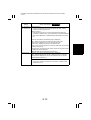
/$"$8+,%/,+--+(#$9!'+& *')/").$!',+'5 2.)*'%+'#$!*%%/
B*)% "%"4
& "'/+')9,0(.+
& "'6/+')9,0(.+
%$
9
#4./.
0)
,
.
3
+:*)--,-7-)
,-
2)--/,
2)--/,)-4
2)--/,
2)--/,%++%.0./0
K//+:*)-
2)--/,
K//+:*)-
%>
FrameMaker Ver5.5E(PC) Di200/Di251/Di351 SWITCHES ON PWBs/TECH. REP. SETTINGS
01.01.26
SWITCHES ON PWBs,
TECH. REP. SETTINGS
17196
FrameMaker Ver5.5E(PC) Di200/Di251/Di351 SWITCHES ON PWBs/TECH. REP. SETTINGS
01.01.26
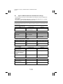
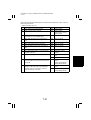
CONTENTS
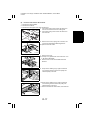
1. CONTROL PANEL KEYS AND TOUCH PANEL ............................................. S-1
1-1. Control Panel Keys .................................................................................. S-1
1-2. Explanation of the Touch Panel ............................................................... S-2
(1) Basis Screen ................................................................................... S-2
(2) Warning Screens ............................................................................. S-3
2. FUNCTION OF SWITCHES AND OTHER PARTS ON PWBs ........................ S-4
2-1. PWB Location .......................................................................................... S-4
2-2. PWB-A (Master Board) ............................................................................ S-4
2-3. PWB-F (Control Panel) ............................................................................ S-5
3. UTILITY MODE ............................................................................................... S-6
3-1. Utility Mode selection Screen .................................................................. S-6
3-2. Utility Mode Function Tree ....................................................................... S-6
3-3. Settings in the Utility Mode ...................................................................... S-7
(1) User’s Choice Mode ........................................................................ S-7
(2) User Management ........................................................................... S-13
(3) Admin. Management ....................................................................... S-14
4. TECH. REP. MODE ......................................................................................... S-16
4-1. Tech. Rep. Mode Menu Screen ............................................................... S-16
4-2. Tech. Rep. Mode Function Setting Procedure ......................................... S-16
4-3. Tech. Rep. Mode Menu Function Tree .................................................... S-17
4-4. Setting in the Tech. Rep. Mode ............................................................... S-18
(1) Tech. Rep. Mode ............................................................................. S-18
(2) System Input .................................................................................... S-21
(3) Administrator # Input ....................................................................... S-22
(4) Counter ............................................................................................ S-22
(5) Function ........................................................................................... S-25
(6) I/O Check ......................................................................................... S-26
(7) Movement Check ............................................................................. S-26
(8) RD Mode ......................................................................................... S-27
(9) ROM Version ................................................................................... S-28
(10) Level History .................................................................................... S-28
5. SECURITY MODE ........................................................................................... S-29
5-1. Security Mode Menu Screen ................................................................... S-29
5-2. Security Mode Setting Procedure ............................................................ S-29
5-3. Settings in the Security Mode .................................................................. S-30
6. ADJUST MODE ............................................................................................... S-32
6-1. Adjust Mode Menu Screen ...................................................................... S-32
6-2. Adjust Mode Setting Procedure ............................................................... S-32
6-3. Adjust Mode Function Tree ...................................................................... S-32
6-4. Settings in the Adjust Mode ..................................................................... S-33
(1) Printer .............................................................................................. S-33
(2) IR ..................................................................................................... S-33
7. INITIAL MODE ................................................................................................. S-34
7-1. Initial Mode Menu Screen ........................................................................ S-34
7-2. Initial Mode Setting Procedure ................................................................. S-34
7-3. Settings in the Initial Mode ....................................................................... S-35
i
FrameMaker Ver5.5E(PC) Di200/Di251/Di351 SWITCHES ON PWBs/TECH. REP. SETTINGS
01.01.26
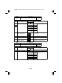
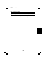
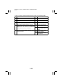
7-4. Data/Conditions Cleared by Reset Switches ........................................... S-36
8. UTILITY MODE ................................................................................................ S-37
8-1. Utility Mode selection Screen .................................................................. S-37
8-2. User’s Choice Function Tree ................................................................... S-37
8-3. Settings in the Utility Mode ...................................................................... S-38
9. SOFT SWITCH SET ........................................................................................ S-39
9-1. Soft Switch Initial Value Table ................................................................. S-39
9-2. Set Contents of Soft Switches ................................................................. S-40
ii
FrameMaker Ver5.5E(PC) Di200/Di251/Di351 SWITCHES ON PWBs/TECH. REP. SETTINGS
01.01.26
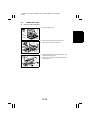
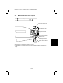
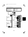
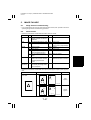
1.
1-1.
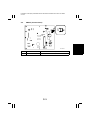
CONTROL PANEL KEYS AND TOUCH PANEL
Control Panel Keys
1
2
3 4
5
6
7
8
9
12
1. Touch Panel
• Shows various screens and message.
2. Utility Key
• Press to show the Utility Mode menu.
11
10
4015O038AA
7. Access Mode Key
• Press to enter the access number when
Copy Track of the Administrator mode
available.
• Press the access Key.
3. Mode Check Key
8. Interrupt Key
• Lists the current settings on the screen.
• Press to select the Interrupt mode.
• Access to register the current settings in a
program.
9. Panel Reset Key
• Press to set the machine into the initial
4. 10-Key Pad
mode, clearing all settings made on the
• The number of copies to be made.
control panel.
• The various numeric values.
10. Clear Key
5. Copy Key
• Clear the various numeric values.
• Press to select the Copy mode.
11. Stop Key
6. Scan Key
• Stop a print cycle.
• Press to select the Scanner mode.
• Stop a scanning cycle.
12. Start Key
• Start a print cycle.
S-1
FrameMaker Ver5.5E(PC) Di200/Di251/Di351 SWITCHES ON PWBs/TECH. REP. SETTINGS
01.01.26
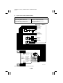
1-2.
(1)
Explanation of the Touch Panel
Basis Screen
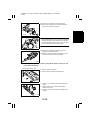
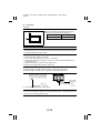
The Basic screen is the initial screen that appears when the copier is turned ON.
1
2
3
5
4011P291CA
4
1. Supplementary Function Keys
• The auxiliary, Density, Orig.
Copy, and Basics keys are displayed.
2. Message Display
• Shows the current machine status, operating instructions and precautions, and other
data including the number of copies selected.
3. Function Display
• Shows the basic function keys and the corresponding functions currently selected for
use.
4. Sub-message Display
• Shows graphic representation of the operating status of a job.
5. Set Function
• Shows graphic representation of the copying type currently selected for use.
S-2
FrameMaker Ver5.5E(PC) Di200/Di251/Di351 SWITCHES ON PWBs/TECH. REP. SETTINGS
01.01.26
(2)
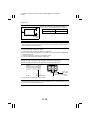
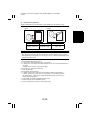
Warning Screens
The Warning screen may be a malfunction display, error display, warning display, or a caution display.
<Malfunction Display>
Given when a malfunction occurs.
E.g.: Malfunctions that can be identified
with a specific code.
<Error Display>
Given when an error occurs.
E.g.: Paper misfeed, door open, etc.
4011P274CA
4012P179CC
<Warning Display>
Given when only a defective copy will be
produced because of erroneous or illegal
panel settings.
E.g.: Unmatched paper size in Auto Paper.
<Caution Display>
Given when, though further copier operation will be possible, it could eventually
result in a malfunction.
E.g.: Toner near empty, etc.
4011P292CA
S-3
4011P293CA
FrameMaker Ver5.5E(PC) Di200/Di251/Di351 SWITCHES ON PWBs/TECH. REP. SETTINGS
01.01.26
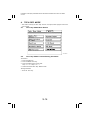
2.
FUNCTION OF SWITCHES AND OTHER PARTS ON
PWBs
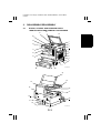
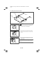
2-1.
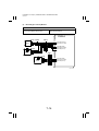
PWB Location
PWB-A
PWB-F
4011D095AA
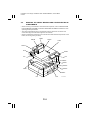
2-2.
PWB-A (Master Board)
4011D093AA
Symbol
S1
Name
Test Print Switch
Description
Produces the test pattern of Function F12.
<Procedure>
1. Press S1 to let the copier start the output
sequence.
2. Press S1 a second time to stop the output
sequence.
S-4
FrameMaker Ver5.5E(PC) Di200/Di251/Di351 SWITCHES ON PWBs/TECH. REP. SETTINGS
01.01.26
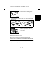
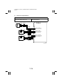
2-3.
PWB-F (Control Panel)
SW37
SW37
4011D095AA
Symbol
SW37
Name
Warm Restart Switch
Description
Used to enter the initial mode.
S-5
FrameMaker Ver5.5E(PC) Di200/Di251/Di351 SWITCHES ON PWBs/TECH. REP. SETTINGS
01.01.26
3.
UTILITY MODE
• Utility Mode is used to make various settings according to the user’s need.
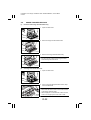
3-1.
Utility Mode selection Screen
• Press the Utility key on the control panel.
4011P294CA
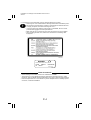
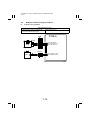
3-2.
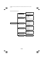
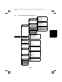
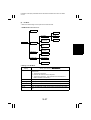
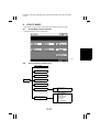
Utility Mode Function Tree
User’s Choice 1/6
User’s Choice 2/6
User’s Choice 3/6
User’s Choice 4/6
User’s Choice 5/6
User’s Choice 6/6
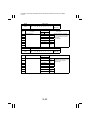
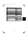
User’s Choice
Meter Count
Utility
Copy Job Recall
User Management
✽1
✽2
Cofirmation Beep
Alarm Volume
Panel Cleaning
Dehumidity
Toner Replenisher
Data Send
Administrator Set
Copy Track
Admin. Management
✽ 1:Set with "Dehumidity" available from Tech. Rep. Mode.
✽ 2:The description of the function is displayed when a Data Terminal is connected to the
machine.
S-6
FrameMaker Ver5.5E(PC) Di200/Di251/Di351 SWITCHES ON PWBs/TECH. REP. SETTINGS
01.01.26
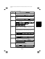
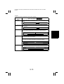
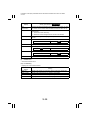
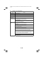
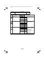
3-3.
Settings in the Utility Mode
Touch Panel
Display
User’s Choice
Setting
User’s Choice is used to make various settings according to the
user’s need.
Meter Count
Displays the counts of various counters.
Copy Job Recall
Permits programming of various functions, including copying jobs.
User Management Permits setting of the various User Management functions.
Admin.
Management
(1)
The entry of the “Administrator #” set using the Tech. Rep. mode permits the settings of the following functions.
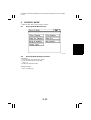
User’s Choice Mode
• User’s Choice is used to make various settings according to the user’s need.
1. User's Choice Function Setting Procedure
<Procedure>
1. Press the Utility key.
2. Touch the “User’s Choice” key.
3. Select the appropriate screen from the menu.
4. Select the appropriate function.
5. After the settings are complete, touch the “Enter” key to validate the settings.
<Exiting the Mode>
• Touch the “Exit” key.
S-7
FrameMaker Ver5.5E(PC) Di200/Di251/Di351 SWITCHES ON PWBs/TECH. REP. SETTINGS
01.01.26
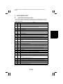
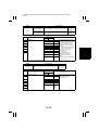
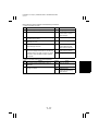
2. User's Choice Function Tree
Memory Recall
User’s Choice 1/6
Mixed Original Detection
Language Selected
Original
Copy Default
Auto Paper/Auto Size
User’s Choice 2/6
Drawer Priority
Special Paper
Multiple-in-1 and Booklet Copy
Zoom
Auto Panel Reset
Energy Save Mode
User’s Choice Mode
User’s Choice 3/6
Plug-In Counter,ID Key Reset
Auto Power Off
LCD Back-light Off
4in1 Copy Order
Density Priority
User’s Choice 4/6
Default Copy Output Levels
Priority Density
Output Priority
Intelligent Sorting
Output Tray
User’s Choice 5/6
“Small” Originals
Scanner Dry
User’s Choice 6/6
S-8
Density (ADF only)
FrameMaker Ver5.5E(PC) Di200/Di251/Di351 SWITCHES ON PWBs/TECH. REP. SETTINGS
01.01.26
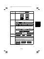
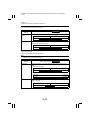
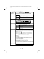
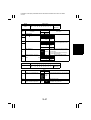
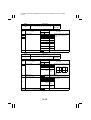
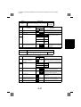
3. Settings in the User's Choice Mode
Touch Panel
Display
Memory Recall
Setting (The default is Highlighted ).
Select whether to enable or disable the Memory Recall function.
ON
Mixed Original
Detection
OFF
Select the priority Mixed Original Detection mode that is automatically
selected when the Power Switch is turned ON or Panel Reset key
pressed.
ON
Language
Selected
OFF
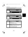
Select the language of the Touch Panel messages.
<Metric Areas>
ENGLISH GERMAN
Original
Default
Copy
<Inch Areas>
FRENCH
ENGLISH FRENCH
JAPANESE
DUTCH
ITALIAN
SPANISH
PORTUGUESE
DANISH
NORWEGIAN
SWEDISH
FINISH
JAPANESE
SPANISH
Select the priority type of Original
Copy setting selected automatically when the Power Switch is turned ON or Panel Reset key
pressed.
Note
• Some type settings are not available depending on the types of
options configured with the copier and the settings made in “Tech.
Rep. Choice.”
1-Sided
Auto Paper/Auto
Size
1-Sided 1-Sided
2-Sided
Select the priority Auto mode (Auto Paper or Auto Size) selected
when the Power Switch is turned ON or Panel Reset key pressed.
Auto Size
Auto Paper
Drawer Priority
2-Sided 2-Sided
Manual
Select the priority paper source that is automatically selected when
the copier is set into the Auto Size or Manual mode.
1st Drawer
2nd Drawer
3rd Drawer
4th Drawer
5th Drawer
Special Paper
Define the type of paper used for each paper source, or designate a
particular paper source for special paper.
Normal
Not for 2-Sided
Recycled
Special
S-9
FrameMaker Ver5.5E(PC) Di200/Di251/Di351 SWITCHES ON PWBs/TECH. REP. SETTINGS
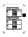
01.01.26
Touch Panel
Display
Multiple-in-1 and
Booklet Copy
Zoom
Setting (The default is Highlighted ).
Select whether to enable or disable recalling a default zoom ratio for
2in1, 4in1, or Booklet Creation.
OFF
ON
Auto Panel Reset
Energy Saver
Mode
Select the time it takes the Auto Panel Reset function, which resets
the panel settings when the set period of time elapses after a copy
cycle has been completed or the last key operated, to be activated.
30 sec.
1 min.
2 min.
3 min.
5 min.
No Reset
Select the time it takes the copier to enter the Energy Saver mode
after a copy cycle has been completed or the last key operated.
• Press the “Clear” key and, Use the 10-Key Pad to set the time.
1 to 240 min. ( 15 min. )
Plug-In Counter,
ID Key Reset
Select whether or not to reset the panel automatically when the
Access Mode key is pressed (in the Copy Track mode) or the Plug-In
Counter is unplugged.
OFF
ON
Auto Power Off
Select the time it takes the Auto Shut Off function, which shuts down
the copier when the set period of time elapses after a copy cycle has
been completed or the last key operated, to be activated.
• Press the “Clear” key and, Use the 10-Key Pad to set the time.
Note:
• The option of “OFF” becomes available on the screen if “Yes” is
selected for “Disable Auto Shut off” of the “Admin. Management”
function.
15 to 240 min.
OFF
✽ Default: 35/25 CPM (60 min.), 20 CPM (30 min.)
LCD Back-light Off Set the time it takes the LCD backlight to turn OFF after a copy cycle
has been completed or the last key has been operated.
• Press the “Clear” key and, Use the 10-Key Pad to set the time.
1 to 240 min. ( 1 min.
✽ 20 CPM: U.S.A. and Canada Only
S-10
)
FrameMaker Ver5.5E(PC) Di200/Di251/Di351 SWITCHES ON PWBs/TECH. REP. SETTINGS
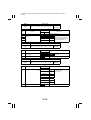
01.01.26
Touch Panel
Display
4in1 Copy Order
Density Priority
Setting (The default is Highlighted ).
Specify the default copying order in the 4in1 mode.
1 2
1 3
3
2 4
4
Specify the priority exposure mode that is selected automatically
when the Power Switch is turned ON or the Panel Reset key pressed.
<Density>
Auto
Manual
<Original Image Type>
Photo
Text
Default Copy
Output Levels
Text/Photo
Auto : Select the priority exposure level in the Auto Exposure mode.
Manual: Select the priority exposure level in the Manual Exposure
mode.
<Auto>
Lighter
Darker
Normal
<Manual>
Darker
Lighter
Priority Density
Set the image density level for printing.
-2
Output Priority
-1
0
1
2
Select the priority finishing type.
Note:
• The contents of the display vary depending on the types of finishing
options mounted on the machine.
Non Sort
Corner Staple
2-Hole Punch
Sort
2-Point Staple
3-Hole Punch
Group
S-11
FrameMaker Ver5.5E(PC) Di200/Di251/Di351 SWITCHES ON PWBs/TECH. REP. SETTINGS
01.01.26
Touch Panel
Display
Intelligent Sorting
Setting (The default is Highlighted ).
Select whether to enable or disable the function that automatically
switches between Sort and Non-Sort according to the number of originals and the number of copy sets to be made.
Applicable when the system is equipped with a finishing option and
using an ADF or ADFR.
OFF
ON
Output Tray
Select the output tray for each application when the system is
equipped with a finishing option.
<Fax>
1
2
3
2
3
<PC Print>
1
<Copy> Displayed when a Job Tray is mounted.
1
2
✽ When a Finisher is mounted: PC Print default setting "2"
“Small” Originals
Select whether to enable or disable a copy cycle when it is initiated
with an original of a small size that is not detectable by the system
placed on the Original Glass.
ON
OFF
✽ Default: Metric areas OFF / Inch Areas ON
Scanner Dry
Set the time-of-day to run a Scanner drying cycle.
Note:
• When entering a value for Hours and Minutes and if it is a singledigit number, first enter a “0.”
Density (ADF only) Adjust the copy image density level when the ADF is being used.
✽ : Initial setting
✽
When the standard original (text, etc.) is
used.
To give better reproduction of faint original.
S-12
!"
#
% & &&'()*&+,)- . '('&*-'/&)' 0)/1-2
&+.&3&44
)-/+&+5. '('&64
3/&&+77)7&*-'/&)'
8 9*&&+ &&'( /)73&:&)-/+&+5'&64&),31&&+ &&'( 0;&'(&+)12
% )-/+&+5'&64
)-/+'3
734
&&'(+1*-3& )'*&)'7 3/&&+,)3-)*&+<=7<&+& )-'1 >+'4)'&+/)'$
&)37'3 7 1))')'&+)-/+'3 &)-/+1
93)3-
8
8
3/&&+,)3-)*&+3
'33''(
. 1&)1 =34 )'&+)-/+'3:33)>'(&+- &)/3'
&+)-/+'3>&+)-&+,'(&)&-''(&+)>>&/+
+-1*4'(
&& 1+-1*4'( ?-'/*)&+-'1/''
)'!73' + !73' + &+ -7734)*&)'
&'1
' & ,)- 1&&)&+'&>+'&'3 )-'&1
$
FrameMaker Ver5.5E(PC) Di200/Di251/Di351 SWITCHES ON PWBs/TECH. REP. SETTINGS
01.01.26
(3)
Admin. Management
• The entry on the “Administrator # Input ” set using the Tech. Rep. mode permits the settings of the following functions.
1. Admin. Management Mode Function Setting Procedure
<Procedure>
1. Press the Utility key.
2. Touch the “Admin. Management Mode” key.
3. Enter the Administrator number from the 10-Key pad.
4. Touch the “Enter” key.
5. Select the appropriate function.
6. After the settings are complete, touch the “Enter” key to validate the settings.
<Exiting the Mode>
• Touch the “Exit” key.
2. Settings in the Admin. Management Mode
Touch Panel
Display
Setting (The default is Highlighted ).
Administrator Set
Displays the Max. Copy Sets and Disable Auto Shut OFF screens.
Max. Copy Sets
Determine the number of copies or copy sets that can be set using
the 10-Key Pad.
1 to 99
OFF
Disable Auto Shut Select whether to enable or disable the setting of the “Auto Shut Off”
Off
function available from User’s Choice.
Copy Track
No
Not displayed.
Yes
Displayed.
Displays the various setting screens including Copy Track.
Copy Track Mode Select the number of accounts to be controlled
OFF
Copy Track Data
100 Accounts 1 100 Accounts 2 1000 Accounts
Select the particular account number.
Output the copy track data.
<Procedure>
Place the required number of sheets of A4L or Letter L paper on the
1st Drawer.
✽ When “All Counter Reset” is touched, it clears all data under control.
S-14
FrameMaker Ver5.5E(PC) Di200/Di251/Di351 SWITCHES ON PWBs/TECH. REP. SETTINGS
01.01.26
Touch Panel
Display
100 Accounts-1
100 Accounts-2
Setting (The default is Highlighted ).
100 Accounts-1
• Copying is authorized only for the accounts, for which Access
Codes have been programmed.
100 Accounts-2
• Permits the accounts, for which Access Codes have been programmed, to make copies. Copy track data can also be maintained
if the Access Mode key is pressed before attempting to make copies.
The copy track data of the selected page is displayed.
“No.”: Enter the set account number from the 10-Key Pad.
“Total Count”: Displays the count of the Total Counter.
“Size Count”: Displays the count of the Size Counter.
“Copy Limit”: Enter the maximum number of copies that can be made
from the 10-Key Pad.
“Access Code”: Enter the access number, which can range from 0001
to 9999, from the 10-Key Pad.
✽ These data can be cleared with the Clear key.
1000 Accounts
The copy track data of the selected page is displayed.
“No.”: Displays the account number. (Setting cannot be changed.)
“Total Count”: Displays the count of the Total Counter. (It can be
cleared with the Clear key.)
Note:
• The account number corresponds to the access code(ID) of that
particular account.
S-15
FrameMaker Ver5.5E(PC) Di200/Di251/Di351 SWITCHES ON PWBs/TECH. REP. SETTINGS
01.01.26
4.
TECH. REP. MODE
• This mode is used by the Tech. Rep. to check, set, adjust, and/or program various service functions.
4-1.
Tech. Rep. Mode Menu Screen
4011P296CA
4-2.
Tech. Rep. Mode Function Setting Procedure
<Procedure>
1. Press the Utility key.
2. Press the Meter Count key.
3. Press the following keys in this order:
Stop → 0 → 0 → Stop → 0 → 1
4. Select the desired Tech. Rep. Mode function.
<Exiting the Mode>
• Touch the “Exit” key.
S-16
!"
#
& ''
+*'-)-(32*'-(
4)
)56*)56
&7&'
*(/'-(4'
('
,2 4--)+,8* '('
2( '&
+( -"(
"+,8* '
+!
2(5'-)- '-(
!2 ''-(4--)
/0!)0-/
/($'0-*20+
!2 ''-(
9--+,8* '
!$ *,'0
--(' *
/0!)-,
& '()*'
):()*'
0(26,9--
/0(-(32*'-(
/0(/52(5:'/'(2)'-(
+,( ''-
.()*'
-*('
)
;
-*<5
1/
('((/
*(/'-(
%$
=
0/
-1('0/
/($'0-*20+
/((
+!
5(( 0
('
( 0
03'&;-<&
+) 2
/((
6)4)0/
!-,
! -(
415 '-&
$%
!"
#
& ' ()*+,-*..-/ ,'+'!0,-1-) ,,*2 *334) ,*, 5 ,,
& ,,'*1-**,(-+-05*2-0,-* -)+'*.
0.5
6),-0
-*(2),-*
80
,,*2'3()., .+,,'00 7 .+,-* +'(-),-,+-2*. 7
3,+,-*
' )*, -)*33,-,'* ,
,*33*+'-,+ 7
,+
' )*, -)*33,-,'* ,
,*33,+ 7
,,' 7(-8
@
@
0.9)0.9
!
@
@#
@
@
.+,/','-*-,,-*:.,' ,,*2-($33
)*32*.
$33
-05().,1.:.(-; < '-+
.9A)0.9 , .+,-*-(..+-05*2-3 "#$
%&
5=5,
, .+,-*-($ 33+-05*2-3 -*.5
.+,/',',-3 0.5,'55(->; *2*,?-(;,.$
,5
1RWHV
+**
)*+,-*8,
+**A)
"'()
.+,/',',-.,,'()*+,-* ,-: ,-*,'+-*,-.0*.-
*-,
*:. ,'()*+,-* ,- ,,'*):-(+-0 ,-
:3B00 -)+B7--,-B*323*$
,5
%
*:. ..()*+,-* *-8,
$%
FrameMaker Ver5.5E(PC) Di200/Di251/Di351 SWITCHES ON PWBs/TECH. REP. SETTINGS
01.01.26
2. Printer
• Make the necessary adjustments of the printer (engine).
Touch Panel
Display
Edge Erase
Setting (The default is Highlighted ).
Set the erase width on the leading, trailing, right, and left edge of the
image.
0 to 5 mm ( 4 mm )
Loop Adjustment
Set the length of the loop to be formed in paper before the Synchronizing Rollers
-5 to +5 mm ( 0 mm )
Image Density
Set the image density for the printer. The value set for this function
becomes the central value of “Priority Density” of User’s Choice.
-3............................................. 0 ............................................+3
Lighter
ATDC Sensor
Gain
Darker
Current: Shows the current ATDC control voltage.
Set: Set the ATDC control voltage.
Note:
• Be sure to record this value when I/C has been changed.
123 ....................................... 155 .......................................186
T/C Greater
VG Adjust
T/C Smaller
Vary the Vg voltage to set the desired image density.
-2............................................. 0 ............................................+2
Lighter
Darker
S-19
FrameMaker Ver5.5E(PC) Di200/Di251/Di351 SWITCHES ON PWBs/TECH. REP. SETTINGS
01.01.26
3. ADFR
• Make the necessary adjustments of ADFR.
Note:
• For details, see Option service manual.
Touch Panel
Display
Original Stop
Position
Setting (The default is Highlighted ).
Adjust the document stop position in each of the ADF modes.
-7............................................. 0 ............................................+7
Smaller
Registration Loop
Greater
Set the length of the loop to be formed in the original fed off the ADF
before the Registration Roller.
-5 mm...................................... 0 .....................................+5 mm
Smaller
Greater
4. Scan-through ADF
• Make the necessary adjustments of AFR.
Note:
• For details, see Option service manual.
Touch Panel
Display
Registration
Setting (The default is Highlighted ).
Adjust registration in the main and sub-scanning directions of the
ADF.
Main Scanning (CD)
-72 dot..................................... 0 ....................................+72 dot
Smaller
Greater
Sub Scanning (FD)
-127 dot................................... 0 ..................................+127 dot
Smaller
Zoom Adjust
Greater
Adjust the scanning zoom ratio in the main and sub-scanning directions of the ADF.
0.990 ....................................... 0 .......................................1.000
Reduction direction
S-20
Enlargement direction
!"
#
!$ %&'(
) '(&*% '+',-,.+/ 0&'(,+'(! &
1RWH
!1234156
,%7(+/
8/9
!$ %&'(
''+.(&-%/' ''(-,7& %0&'(/,+.'(-,%&. ,-'(88
//
"'
#,,+' %
) 1&*% ''(7+' 0&'(+,,7,89+.
1RWH
!1234156
,%7(+/
8/9
,,+'
%
''+.(&-%/' 1&*% ''(7+' 0&'(
//
"'
) (-%+7',+//,0 '(7(!8',&-+'(88 :+8%'4+& ''+. ,%7(+/
8/9
''+.(&-%/' 8:+8%'
''(88 :
;,7&%<
/7''(88 ,%7
/7''(88 :-+,+ '+&& : ',=% &4+'
'(88 :-,'($>9&
,%7(?@',A/&''(+0 ''+.
(+.B&
C,,
(+.-B&:,,',',& &A/%
;,7&%<
,%7('(9,-'(-B&:,,',',=7(+.&
'(/9 '(+'%8'9',%+&,'(7/+.
,8',+4 ',+.'(,.+/ ''+.
+''(+0',-,'($>9&
D ,%7(?+8%'@',A/&''(+0 ''+.
$
!"
#
+(3.'5
,56
3.'
+'*-(&+'
&&'-.1*(5& ,56 &.3.'3+'*-(&+' &&( 3.'35+
'&&. 5'()'1+&.1&
-'59
&3&',&+'
53&/28.'&.+,&+'5-'59&3&'-' + +('&1
% &''()*++,''-&./01''-'&+12 3'+*4&5&6+1
*+&.$761
% .+8 &.'()+*3+, 1+'3.,, 9+&6,
:5'-+('&;
,'&.3+('&'( 3'
53&&.3+('&&+)351
&.56
< +(3./2
&.'&(,&6&+('1+&.35'-+,&+'= &+'-&.+-'53+('&
✽ >?*>'1>?*>+*>>3''+&)351.6(&+&3556 &
8.''8 ' &551
:5'-055+('& +*+('&6,&'3;
+(3.&./+('&! &26
53&&.3+('& &+)35155&+'3
+(3./72
+(3.'5
,56
,
&&'+('& &.'()+* .& +*,,( 133+1'-&+&. 9'1
&6,
, 9
,6,
0
@A
+5
<
@<
!36351
0<
?&&
,35
?-5
+&*+$ 11
0
@3
?
$@B$
$
FrameMaker Ver5.5E(PC) Di200/Di251/Di351 SWITCHES ON PWBs/TECH. REP. SETTINGS
01.01.26
Touch Panel
Display
Jam
Setting
Counts the number of misfeeds that have occurred at different locations in the copier.
Display
Display
MCBJ System
MCBJ Machine Only
1st Drawer
2nd Drawer
3rd Drawer
4th Drawer
5th Drawer
Manual Feed
Vertical Transport
Separator
Fusing
Duplex Entrance
Duplex Feed
LCC Feed
Display
Display
LCC Transport
Shift/Job Tray Transport
Shift/Job Tray Exit
Finisher Horizontal Transport
Finisher Transport
Finisher Exit
Finisher Staple
Finisher Set Transport
MDBJ
ADFR (Scan-through ADF) Feed
ADFR (Scan-through ADF) Transport
ADFR Reverse
SADF
Display
Printer
Engine
✽ MDBJ: ADFR paper feed counter divided by ADFR misfeed counter
✽ Printer: No. of misfeeds occurred due to communication errors between
memory and printer.
✽ Engine: No. of misfeeds occurred due to communication errors with the
engine.
PM
Counts the frequency of use of each of the different parts of the
copier.
Display
I/C Life 1
I/C Life 2
1st Drawer
2nd Drawer
3rd Drawer
4th Drawer
5th Drawer
Description
No. of A4C copies made, translated from the period of
time through which the I/C motor has been energized.
No. of A4C copies made, translated in terms of A4C
length from the total FD length copied
No. of sheets of paper fed from the 1st Drawer
No. of sheets of paper fed from the 2nd Drawer
No. of sheets of paper fed from the 3rd Drawer
No. of sheets of paper fed from the 4th Drawer
No. of sheets of paper fed from the 5th Drawer
Display
LCC Parts 1
LCC Parts 2
Other PM Parts 1
Other PM Parts 2
Other PM Parts 3
1-Sided
2-Sided
Description
No. of sheets of paper fed from the LCC
No. of sheets of paper fed from the LCC
No. of times a sheet of paper is fed through
No. of times a sheet of paper is fed through
No. of times a sheet of paper is fed through
No. of times a 1-sided original is fed through
No. of times a 2-sided original is fed through
S-23
FrameMaker Ver5.5E(PC) Di200/Di251/Di351 SWITCHES ON PWBs/TECH. REP. SETTINGS
01.01.26
Touch Panel
Display
Setting
PM
Display
SADF
IR 1
IR 2
Job Tray
Toner Pages
Fusing Unit
Trouble
Description
No. of single feeds
No. of scan motions
No. of scan motions
No. of cycles of feeding paper out into Job Tray
No. of pages equivalent to the no. of black dots on A4
original with B/W 5%
No. of times a sheet of paper is fed out
Counts the number of malfunctions that have occurred at different
parts of the copier.
Malfunction
Code
C0000
C0010
C0045
C004C
Malfunction
Code
C0520
C0650
C0651
C0990
Malfunction
Code
C0B00
C0B20
C0B30
C0B38
Malfunction
Code
C0B50
C0B54
C0B73
C0B78
Malfunction
Code
C1038
C1300
C133A
C133B
Malfunction
Code
C0214
Description
Main Motor
I/C Motor
Cooling Fan
Ventilation Fan
Description
Fuser High Temperature
Home Sensor
Left Sensor
LCC Transport Motor
Description
Transport Drive Motor
Stapler Unit
Paper Aligning Bar Unit
Paper Standard Board Unit
Description
Staple 1 Unit
Staple 2 Unit
Punch Cam Motor Unit
Punch Switching Motor Unit
Description
Engine Connection
Polygon Motor
Communication Error (G/A)
Communication Error (Option)
Description
Transcribable Volt.
S-24
Malfunction
Code
C004E
C0070
C0500
C0510
Malfunction
Code
C0991
C0995
C0999
C099D
Malfunction
Code
C0B48
C0B4A
C0B4D
C0B4E
Malfunction
Code
C0B80
C0BA0
C0F32
C0F33
Malfunction
Code
C13C0
C13D0
C13F0
C18XX
Description
Cooling Fan (Power Supply)
Toner Bottle Motor
Fusing Warming-up
Fuser Low Temperature
Description
LCC Lift 1 Limit
LCC Lift Motor
LCC Lift 2 Limit
LCC Communication
Description
Pressure Motor 1 Unit
Pressure Motor 2 Unit
Assist Tray Unit
Transaction Tray Unit
Description
Shift Unit
Elevate Motor
ATDC Sensor
ATDC Adjust
Description
I/C Initial Error
EEPROM
HSYNC(SOS)
Printer Controller Error
FrameMaker Ver5.5E(PC) Di200/Di251/Di351 SWITCHES ON PWBs/TECH. REP. SETTINGS
01.01.26
Touch Panel
Display
Device
Setting
Shows the numbers of prints for different applications. It also allows
the Tech. Rep. to clear each counter.
Display
Copier
Printer
Report Print
FAX Print
FAX Transmission
Mail Transmission
Maintenance
Description
No. of prints made by copier
No. of prints made by printer
No. of report prints made
No. of fax prints made
No. of prints made for fax transmission
No. of prints made for mail transmission
Set different count values for the Maintenance Counter.
When the count reaches the preset value, the icon “ ” appears in
the Sub-Message Display.
<Procedure>
1. Touch “Maintenance (Set)”.
2. Press the Clear key to clear the current value.
Press the Interrupt key to undo the clearing operation, restoring
the original value.
3. Enter the value from the 10-Key Pad.
(5)
Function
• This function allows the Tech. Rep. to make the various function tests and adjustments.
Touch Panel
Display
Setting
F1
<Paper Passage>
A check is made for paper passage performance.
<Procedure>
1. Select the paper source.
2. Press the Start key to start the paper passage cycle.
3. Press the Stop key to stop the paper passage cycle.
F2
This test is for factory adjustment only and should NOT be used.
F7-1
<Original Size Detecting Sensor Adjustment>
Automatically adjusts the threshold level of the Original Size Detecting Sensor.
✽ For details, see DIS/REASSEMBLY, ADJUSTMENT.
F8
<ATDC Sensor Automatic Adjustment>
This test is for factory adjustment only and should NOT be used.
F12
<Test Pattern>
Outputs the test pattern.
<Procedure>
1. Select the paper source.
2. Press the Start key to start the output sequence.
3. Press the Stop key to stop the output sequence.
S-25
!"
#
% &' (&)*+'(,+,) + , ,*'&+/
-/0
((+1
'+$(&,*1&2 ✽ ,.(/ 3 -(,+ 4'+*/
'++
✽ ,.(/ 3 -(,+ 4'+*/
2!
✽ ,.(/ 3 -(,+ 4'+*/
/++ &
✽ ,.(/ 3 !2563278
+(
✽ ,.(/ 3 !2563278
+ &
✽ ,.(/ 3 -(,+ 4'+*/
&)(07,90 ✽ ,.(/ 3 -(,+ 4'+*/
% !*+ -').'&+ (,'&'),,-(,+
,*'&+/
-/0
((+1
2-
1
--- 1'&'(&,*1&(&2
:,'.*;
/'((&--- 1,.
/'--,+(&,'*+(.0
(&((0
'++
&' (&'++),,-(,+
% 4 (&),)'(,0.<* (+(,+/0+. &,*/.!9
* .
% *+ (&=-, *5-
% ,4 (&'++3(&. (+',),4+(9+1 -').),
(&$>0.
:,'.*;
+((&. (+',),4+(),(&$>0.
,*'&?(@
=-5-&' &' (&+(+ (0,)(&=-, *5-/1&(
$#
FrameMaker Ver5.5E(PC) Di200/Di251/Di351 SWITCHES ON PWBs/TECH. REP. SETTINGS
01.01.26
(8)
RD Mode
• Make the initial settings of the copier for the Data Terminal.
1. RD Mode Menu Function Tree
ID Code
CT-ID
RD Mode
DT Setting
DT-ID
Initial
Transmisson
TEL. #
Maintenance
Counter
Clear
Call
Completion
RAM Clear
Dial Mode
Common DT
Auto Receive
Result Code
2. Setting in the RD Mode
Touch Panel
Display
Setting (The default is Highlighted ).
ID Code
Enter the ID code.
<Procedure>
1. Touch the ID Code key.
2. Enter the ID code from the 10-Key Pad.
3. Touch the ID Code key. (This executes the transmission of
MAINT. START to the Center.)
Maintenance
Displays the various setting screens.
DT Setting
Displays the setting screens for CT-ID, DT-ID, and telephone number.
CT-ID
Enter the ID number of the Center PC from the 10-Key Pad.
DT-ID
Enter the ID number of the Data Terminal from the 10-Key Pad.
TEL No.
Enter the telephone number of the modem connected to the Center
PC.
S-27
FrameMaker Ver5.5E(PC) Di200/Di251/Di351 SWITCHES ON PWBs/TECH. REP. SETTINGS
01.01.26
Touch Panel
Display
Setting (The default is Highlighted ).
Initial
Transmission
Performs the initial transmission from the PPC to the Center to check
for correct communication after the Data Terminal has been set up.
Counter Clear
Clears the spare counter.
<Procedure>
1. Touch the Counter Clear key.
2. Select the number assigned to the counter to be cleared.
Call Completion
Transmits the signal of notifying the completion of service job to the
Center.
RAM Clear
Initializes the Data Terminal settings.
YES
NO
Common DT
Displays the screens for communications settings.
Dial Mode
Sets the type of telephone line of the user.
Pulse
Tone
Auto Receive
Sets the auto reception function.
YES
Result Code
(9)
NO
Set the value according to the type of the modem on the copier.
ROM Version
• Shows the ROM versions.
(10) Level History
• Displays the various level histories.
Touch Panel
Display
Setting
ATDC Set
Displays the voltage set with ATDC Sensor Automatic Adjustment.
ATDC Current
Displays the ATDC Sensor T/C setting in percentage.
Vg Current
Displays the current value of the grid voltage.
Vb Current
Displays the current value of the developing bias voltage.
S-28
!"
#
& '(()* +,-,!.+) ++,/)0 -)01+ o
<=>'
2)-304
,)*+,-,!.)310 -1
+,5)(()*167 1+, )38
+).→ %
(-++,.+-0(501-+)1
29+16+,)34
& )0-,+,:;7
$%
FrameMaker Ver5.5E(PC) Di200/Di251/Di351 SWITCHES ON PWBs/TECH. REP. SETTINGS
01.01.26
5-3.
Settings in the Security Mode
Touch Panel
Display
Total Counter
Size Counter
Setting (The default is Highlighted ).
Select the condition by which the Counter count is increased.
Mode 1
1 Copy per 1 copy cycle
Mode 2
Multiple count-up according to paper size 1/2-sided
copying
Mode 3
Multiple count-up according to paper size 1/2-sided
copying
Select the size of the paper to be counted by the Size Counter.
A3/11x17
No Count
A3/B4/11x17/Legal
A3/B4/11x17/11x14/Legal/FLS
Copy Kit Counter
Copy Kit
Select whether to enable or disable the “Copy Kit count.”
Mode 1
Disables the Copy Kit counter.
Mode 2
Copying not inhibited after the count reaches the
present value.
Mode 3
Copying inhibited after the count reaches the
present value.
Enter a value for the Copy Kit Counter.
When the current value reaches the set value, the following display is
given.
• Copy Kit Counter setting
Mode 2: The icon “
” appears in the sub-message display.
Mode 3: The maintenance call reminder “M4” appears and the
initiation of a new copy cycle is inhibited.
<Procedure>
1. Touch “Set.”
2. Press the Clear key to clear the current setting.
If the setting is accidentally cleared, press the Interrupt key to
undo the clearing operation.
3. Enter the desired value from the 10-Key Pad.
4. Touch “Current.”
5. Press the Clear key to clear the current value.
If the current value is accidentally cleared, press the Interrupt key
to undo the clearing operation.
Plug-In Counter
Select the condition by which the Counter count is increased.
Copy Made
S-30
Copy Cycles
!"
#
&'/1(,
*,2
62&'()
))(3145',) +LJKOLJKWHG ))&78562&'() *,'334(
1RWH
!
(4&&4
2))
))1(), /(//&4(3)&)1)2*&59(4&&'()4&()1
/&*
&(
2))
4
%&'()$'*+,&*2(3
$44
:
:&)1
)1()1& )
&),
&4
$44
) :
:&)1
)1()1& )
) :
&4
&4
&4
&),
:
$44&),
0
0
0
$44:
0
&),+2//&'()
0
0
:+2//&'()
0
0
0
0
0
,'3$(
&'()
&'()(3
/&*
&'()(3
/&*2/2/,
.&/&'()./&'()./&'() 0.0/&'()
$
FrameMaker Ver5.5E(PC) Di200/Di251/Di351 SWITCHES ON PWBs/TECH. REP. SETTINGS
01.01.26
6.
ADJUST MODE
• Used at the factory for making adjustments.
6-1.
Adjust Mode Menu Screen
C1166P002CA
6-2.
Adjust Mode Setting Procedure
<Procedure>
1. Show the Tech. Rep. mode menu screen.
2. Press the following keys in this order:
Stop → Start
3. Select the desired function.
✽ Use the Access Mode key to enter a + or - sign.
<Exiting the Mode>
• Touch the “END” key.
6-3.
Adjust Mode Function Tree
Printer
Registration (CD)
Registration (FD)
Adjust
IR
S-32
Registration
Zoom Adjust
FrameMaker Ver5.5E(PC) Di200/Di251/Di351 SWITCHES ON PWBs/TECH. REP. SETTINGS
01.01.26
6-4.
(1)
Settings in the Adjust Mode
Printer
• Adjust functions relating to the printer.
• Runs a test print sequence.
Touch Panel
Display
Registration (CD)
Setting
Adjust registration in the CD direction on the engine side.
-4.0........................................... 0...........................................+4.0
Smaller
Registration (FD)
Greater
Adjust registration in the FD direction on the engine side
35 CPM
-19............................................ 0............................................+19
Smaller
Greater
20/25 CPM
-26............................................ 0............................................+26
Smaller
Greater
✽ 20 CPM: U.S.A. and Canada Only
(2)
IR
• Adjust functions relating to the I.R.
Touch Panel
Display
Registration
Setting
Adjust registration in the CD and FD direction on the IR side.
Main scanning (CD)
-72 dot...................................... 0......................................+72 dot
Smaller
Greater
Sub scanning (FD)
-24 dot...................................... 0....................................+127 dot
Smaller
Zoom Adjust
Greater
Adjust the zoom ratio in the CD and FD direction on the IR side.
0.990 ..................................... 1.000 .....................................1.010
Smaller
Greater
S-33
FrameMaker Ver5.5E(PC) Di200/Di251/Di351 SWITCHES ON PWBs/TECH. REP. SETTINGS
01.01.26
7.
INITIAL MODE
• Used to initialize the various service functions.
7-1.
Initial Mode Menu Screen
4011P297CA
7-2.
Initial Mode Setting Procedure
<Procedure>
1. Press the Warm Restart switch. Then “.” appears at the center on the left side of the
screen.
2. Enter “3” from the 10-Key Pad.
3. Select the desired function.
<Exiting the Mode>
• Touch the “Exit” key.
S-34
!"
#
%&'()*
+*,
%,*
--).(/0&*- * **/-
?
%&'()*1/2
%'- /3-%))-( ) -3%0-(%&'()*
4%'/&5
6 7&)-**,-%&'(-(0%&+%)- /8-(9%)-( ') ) -&'-/:,-(%8
1RWH
%-**
* **%0-(*'-%)''%&)- )/%+,'$*-//-
?
-).1
--(-).
@
.-*
-(
* -(./-
?
1;-*
* -(0<$*-/ --). ✽ %/-* = -(1;3')&*
--
--(/-)/-$%0$/,0%-)-).
--(->%)
--(,*.(-3. &-
%&:*! -
! - -(*0&)'-%)/ +*,
$
FrameMaker Ver5.5E(PC) Di200/Di251/Di351 SWITCHES ON PWBs/TECH. REP. SETTINGS
01.01.26
7-4.
Data/Conditions Cleared by Reset Switches
Clearing Method
Side Cover
open/close
Trouble
Reset
Memory
Clear
Total Clear
Data Cleared
❍
–
❍
–
Fusing
–
❍
❍
–
Others
Misfeed display
Malfunction
display
❍
❍
❍
–
Erratic operation/display
–
❍
❍
–
Job/Image
–
–
❍
–
User’s Choice
–
–
❍
–
Tech.Rep.Mode
–
–
❍
–
Security Mode
–
–
❍
–
Touch Panel Adjust
–
–
❍
–
Copy Track function data
–
–
–
❍
Electronic Counter counts
–
–
–
❍
❍:Cleared
–:Not cleared
S-36
!"
#
& '()(*+, - ,(+.+- ((/0 11+,/0(+(2- 3 /,
& (2'()(**+/(21+/(+)4/)
56
7
' 3 2+1
(+-/(
+4*8+9!1))
'()(*
' /0/(
7,//0/(
!4+(
+(+1+)1
.1))!4+(
/(//1+,
1+/(/(
) 4)*
+:(;(12(
+*-4
)-4
+-12/)7,<
$%
!"
#
!
"
+-12/)
4)*
((/0
' 3 2+1
☞ '()(*+,$#
(+-/(
☞ '()(*+,$#
+4*8+9!1))
☞ '()(*+,$#
' /0/( ☞ '()(*+,$#
7,/
/0/(
!4+(
☞ '()(*+,$#
+(+1+)1
✽ +,() > (27?.1/-)
.1))!4+(
+-12/[email protected]))!4+(A;)))((21+44+,-11-/()* (
12+1,(+:(2.+- /, /(//1
+,
1+/(/(
✽ +,() > (27?.1/-)
) 4)*
✽ +,() > (27?.1/-)
+:(;(12(
☞ +:(;(12($6
+*-4
✽ +,() > (27?.1/-)
)-4
+,-1 2,1+4*,(- ,:+/)* +:/(/),(
4908
& :+((4(/0(+4+,-1(22,1+4*,(>: (/((2/$
()+,>B(:+(>/,(2//((2/(//1+,
& 22,1+4*,(/.+). 9+-(40 +-12/)7,<
☞ /()+,$5
$=
!"
#
& '()*+*+ ),+' ),+ -+(' . (/.*01,)). 0+.+)()21*3
& '✽ *.(+ ).()*+**3+ +'+(*/ +(().*3+)+'4 5 (')(6,)720
).
;
<
!
<
<
=*3430(+.
<
207420763*0 )21,40+6:4+)2:4+)>6*:220(+)*6)+1
:220(+)*4+)(06 (*,+2*0 +2(,(+)*
?
<
40+20$*$*.))0+)21@))6043$*)4*+6A1! +
<<
:4+)*0! +
<
*31B).
<#
CC
:4+))-,,
8*+0B04,)$(2)268*+0B04,)
$(2)2*.
$(2)2
<D
=($03'+,,
<E
-)+1
<%
E
<*)21.6* +1)+163*0312
<
<<
,40+)214+24+=B0 6* +1:)*016,40+)214+24+=B0
)1!(0067.3*0+(+)*
✽
<
).+()216)+1* +1
<
E
)+1)+).6)+1+20*3).()216)+14*(').()216*+003*+
)+*3
✽
✽
<
<
:;04+24+*2(,(+)*6*+4+24+*2(,(+)*6*+4+24+*
2(,(+)*6)214+24+*2(,(+)*6:;04+24+*2(,(+)*
✽
<<
:
3)2 )*'*! B*32(+1*')21)1()21
<
#
),+)*26:0)04
#
)4*.)04++*3)*+))*()216*++)*),3 '** ' )**(+.()216B (**0)+6 /0:4+)'4+,,
✽
<#
✽
<D
#
7)21+ 6+)21F4*++1=+()21
<E
DE
.3 6=,+)22(,(+)*6$*.$,$=, 201++*3
<%
)+.,*.
<
)+.,*.
<
CC
+*+)*().()218*+0B046<8*+0B04
<
E
)+0)4*+6>)4*+6)21A+)4*+
<
<E
043$*)4*+6A1)4*+6*.)).63*0>+(+*32+)*
<<
E
:4+)2()*,34+)*6=26)21).=+()216G00G3*0 64*(+)*
=+6)*$ +*.. >)3*02)( *3-'*:!*.:<=++22 0(+.
()21
<
3F40+1).:.H4 +*+()21
<#
)+.,*.
<D
CC
,40+++*3)4*+10 ,(+)*()21CC8,, (().*3+)+' +()4*+1
<E
)+.,*.
<%
)+.,*.
<
DE
B (**)4+
✽ 89:*.*.*01
$%
✽
FrameMaker Ver5.5E(PC) Di200/Di251/Di351 SWITCHES ON PWBs/TECH. REP. SETTINGS
01.01.26
9-2.
Set Contents of Soft Switches
NOTES
• The contents of the software switches are described mainly for modes related to copying.
• The mark ✽ indicates a mode containing items that can be set according to the user's
choice, for example.
• The highlighted areas are the initial settings.
Mode
400
Bit
Initial value
Bit:
7
6
5
4
3
2
1
0
0
0
0
0
0
0
0
0
Logic
Function
0
1
HEX: 00
Description
7
Memory Recall
OFF
ON
[ON/OFF] selection for storing the image data
and recalling the image after the end of
copying.
6
Mixed Original Detection
OFF
ON
Selection of mixed original mode that has priority when the power is ON and the Panel
Reset key is pressed.
Fixed
5-0
Mode
401
Bit
7-2
Setting change inhibit
Initial value
Bit:
Function
Language Selected
7
6
5
4
3
2
1
0
0
0
0
0
0
1
0
0
Logic
0
Description
1
Bit7-2:
HEX: 04
000000 Japanese
000001 English
Selects the language to be displayed on the touch panel.
-
000010 Arbitrary
setting
111111
5-0
Fixed
S-40
Setting change inhibit
FrameMaker Ver5.5E(PC) Di200/Di251/Di351 SWITCHES ON PWBs/TECH. REP. SETTINGS
01.01.26
Mode
402
Bit
Initial value
Bit:
7
6
5
4
3
2
1
0
0
0
0
0
0
0
0
1
Logic
Function
0
Description
1
7
Simplex/Duplex
1-Sided 2-Sided
6
Original
Bit6-5:
Copy Default
00
5
4
✽
Auto Paper/Auto Size
1-Sided
01
2-Sided
other
Setting
inhibit
Bit4-3:
3
00
APS
01
AMS
10
Setting
inhibit
11
2
1
Priority Application (auto clear,
screen after panel reset) Specification
✽
Printer
Bit1-0:
00
FAX
01
COPY
Mode
403
Bit
10
AUTO
11
Scanner
Sets the initial status screen
(copy, FAX, AUTO or scanner).
Initial value
Bit:
7
6
5
4
3
2
1
0
0
0
0
0
0
0
0
1
Function
Multiple-in-1 and Booklet Copy
Zoom
7
Logic
0
1
Recommende
d magnification
Full
Size
Fixed
6-1
0
Sets the print form for overseas PC printing.
Copy: All PC prints are output together after
data is received.
Printer: PC prints are output successively
each time data is received.
Copy
0
APS: Auto paper mode
AMS: Auto magnification mode
Manual
✽
Main Application
HEX: 01
Plug-In Counter,ID Key Reset
OFF
HEX: 01
Description
Sets magnification when 2in1, 4in1, booklet or
2in1 division is selected.
Setting change inhibit
ON
S-41
[ON/OFF] selection of panel reset when
Access Mode key is pressed.
FrameMaker Ver5.5E(PC) Di200/Di251/Di351 SWITCHES ON PWBs/TECH. REP. SETTINGS
01.01.26
Mode
404
Bit
7
Initial value
Bit:
7
6
5
4
3
2
1
0
0
0
0
0
0
0
0
1
Logic
Function
0
Auto Panel Reset
Description
1
Bit7-0:
00000000
No Reset
5
00000001
1 min.
4
-
6
3
11110000
2
11111111
30 sec.
1
Other
Setting
inhibit
405
Bit
7
Setting of whether or not auto
clear takes place after the specified time from the end of copying
or a key operation and also the
time setting.
1-minute steps
240 min.
0
Mode
HEX: 01
Initial value
Bit:
Function
Energy Save Mode
7
6
5
4
3
2
1
0
0
0
0
0
1
1
1
1
Logic
0
Description
1
Bit7-0:
00000000
Setting
inhibit
5
00000001
1 min.
3
00001111
2
-
-
6
4
1
11110000
0
Other
S-42
HEX: 0F
15 min.
240 min.
Setting
inhibit
Setting of auto preheat time after
the specified time from the end of
copying or a key operation.
1-minute steps
FrameMaker Ver5.5E(PC) Di200/Di251/Di351 SWITCHES ON PWBs/TECH. REP. SETTINGS
01.01.26
Mode
Initial value
20-cpm Copier
406
Bit
7
Bit:
25-cpm Copier
35-cpm Copier
Bit:
7
6
5
4
3
2
1
0
0
0
0
1
1
1
1
0
7
6
5
4
3
2
1
0
0
0
1
1
1
1
0
0
Logic
Function
0
Auto Power Off
Bit7-0:
5
00000001
3
00001110
1
00111100
• Setting of whether or not to cut
OFF the power to the machine
after the specified time from
the end of copying or a key
1 min.
operation, and also the time
setting
•
When MODE 416 Bit0 "Auto
30 min. *1
power off cancel" is set to
"Enabled", the setting
becomes "No".
60 min. *2
1-minute steps
No FAX: Auto power OFF
With FAX: Heater OFF
240 min.
*1: Initial value for a 20-cpm
Copier
Setting
*2: Initial value for 25-cpm Copier
inhibit
and 35-cpm Copier
OFF
-
2
-
4
-
00000000
HEX: 3C
Description
1
6
HEX: 1E
11110000
0
Other
✽ 20 CPM: U.S.A. and Canada Only
Mode
407
Bit
7
Initial value
Bit:
Function
LCD Back-light Off
7
6
5
4
3
2
1
0
0
0
0
0
0
0
0
1
Logic
0
Description
1
Bit7-0:
00000000
Setting
inhibit
5
00000001
1 min.
-
6
4
3
11110000
240 min.
2
1
Other
0
S-43
HEX: 01
Setting
inhibit
Setting of the back light OFF time
after the specified time from the
end of a key operation
1-minute steps.
FrameMaker Ver5.5E(PC) Di200/Di251/Di351 SWITCHES ON PWBs/TECH. REP. SETTINGS
01.01.26
Mode
408
Bit
7
Initial value
Bit:
7
6
5
4
3
2
1
0
0
0
0
0
0
0
0
0
Logic
Function
0
Drawer Priority
Bit7-4:
0000
5
0001
4
Mode
409
7
Setting of paper source selected
preferentially in the APS (auto
paper mode) or the manual
2nd Drawer mode.
1st Drawer
0010
3rd Drawer
0011
4th Drawer
0100
5th Drawer
1010
Manual
Feed
1100
LCC
Other
Setting
inhibit
Fixed
3-0
Bit
Description
1
6
Setting change inhibit
Initial value
Bit:
7
6
5
4
3
2
1
0
0
0
0
0
1
0
0
0
Logic
Function
4in1 Copy Order
0
✽
Bit7-6:
00
Pattern 1
01
Pattern 2
Other
Density Priority
Original Image Type
AE
Bit5-3:
Setting
inhibit
Setting of image layout sequence
for 4in1 copy operation.
Pattern 2
Pattern 1
1
2
1
3
3
4
2
4
20-cpm Copier and 35-cpm
Copier only
Manual Density mode setting
0000
0100
1000
4-1
0
HEX: 08
Description
1
6
5
HEX: 00
Text/Photo When MODE 409 Bit5 is set to
"AE (auto)", the "Photo mode"
cannot be set.
Photo
Text
1100
Special
image
quality
Other
Setting
inhibit
Fixed
✽ 20 CPM: U.S.A. and Canada Only
S-44
Setting change inhibit
FrameMaker Ver5.5E(PC) Di200/Di251/Di351 SWITCHES ON PWBs/TECH. REP. SETTINGS
01.01.26
Mode
410
Bit
7
Initial value
Bit:
7
6
5
4
3
2
1
0
0
1
0
0
0
1
0
0
Logic
Function
0
Default Copy Output Levels
Description
1
Bit7-6:
6
00
Darker
01
Normal
10
Setting
inhibit
11
4
Setting change inhibit
Density (ADF only)
Normal
3-0
Default Copy Output Levels
Bit3-0:
Bit
7
EXP 1
0001
EXP 2
0010
EXP 3
0011
EXP 4
0100
EXP 5
0101
EXP 6
0110
EXP 7
0111
EXP 8
1000
EXP 9
Other
Setting
inhibit
Setting of the manual density
level selected when the mode is
initialized, and also the level
selected when the mode is
changed from auto density to
manual density.
EXP1 [Lighter]
EXP5 [Normal]
EXP9 [Darker]
Initial value
Bit:
7
6
5
4
3
2
1
0
0
0
0
0
0
0
0
0
Logic
Function
Code Bit (copy)
0
1
+
-
Fixed
6-3
2-0
0000
→
411
Normal:
Black
Image is read at the specified density.
streak
Black streak prevention:
prevenImage is read at a "lighter" density than the
tion
specified density.
→
Mode
Selection of level in auto density
mode.
Lighter
Fixed
5
HEX: 44
Priority Density
✽
Bit2-0:
HEX: 00
Description
Sets the + or - direction of Priority Density of
MODE 411 Bit2-0.
Setting change inhibit
000
0
001
1
010
2
011
Other
S-45
3
Setting
inhibit
Sets the image density for making a print, by varying the developing bias.
FrameMaker Ver5.5E(PC) Di200/Di251/Di351 SWITCHES ON PWBs/TECH. REP. SETTINGS
01.01.26
Mode
412
Bit
7
Initial value
Bit:
7
6
5
4
3
2
1
0
0
0
0
0
1
0
0
0
Logic
Function
✽
Priority Sort Mode
Description
0
1
Bit7-6:
00
Non Sort
01
sort
10
Setting
inhibit
6
HEX: 08
Selection of the paper exit mode
that has priority when the paper
exit system option is installed.
11
Group
OFF
ON
Can be set simultaneously with a mode other
than "Non-sort" of MODE 412 Bit 7-6.
OFF
ON
Can be set simultaneously with each mode of
MODE 412 Bit 7-6.
3
OFF
ON
Setting of changeover, or no changeover,
between sort and non-sort according to the
number of originals and the key operation.
2-0
Fixed
5
Priority Stapling Mode (copy)
4
Priority Punch Mode (copy)
✽
Intelligent Sorting
✽
Mode
413
Setting change inhibit
Initial value
Bit:
7
6
5
4
3
2
1
0
0
0
0
1
0
1
0
0
Logic
Bit
Function
7
FAX (Mail) Output Bin Specification
✽
0
1
Bit7-6:
00
01
6
10
11
5
4
PC Print Output Bin Specification
Bit5-4:
PC Print Output Bin Specification
Description
1st Drawer • Setting of tray to exit FAX
(mail) prints when a finisher is
installed.
• "Option tray" is effective
when the option tray is
Option tray
installed.
Setting
inhibit
Elevator
tray
00
1st Drawer
01
Elevator
tray
✽
HEX: 14
10
Option tray
11
Setting
inhibit
• Setting of tray to exit PC
prints when a finisher is
installed.
• "Option tray" is effective when
the option tray is installed.
✽
1 bin
2 bins
Setting of the bin to exit PC prints when a job
tray is installed.
2
Copy Output Bin Specification ✽
1 bin
2 bins
Setting of the bin to exit copies when a job
tray is installed.
1
FAX (Mail) Output Bin Specification
✽
1 bin
2 bins
Setting of the bin to exit FAX (mail) prints
when a job tray is installed.
3
0
Fixed
S-46
Setting change inhibit
!"
#
'(
%%
)*+,+-
*.
&
#
-)1*')
&
3'4 ')5)
! ,)341*6)5'46
'61'46
*&$%.
'(
#
&
:
;
*5
**)3
)58*
)*+,+-
*.
&
#
%
2'31
-)1*')
*$.
'*')
#
%
')9*')4
✽
*5
✽
'*')
%
*$.
*5
$
)L[HG
$%&
**)3'9 '-)(,'+-'9*')
**(<5)6 4 (
**)3
)58*
0+'+-
/.#
14*')
%
)(1* *5'6 ,
141*641'461'),*()*'
31'4 ')7)(
, '6141*689'
**'9 1)))3711'()3*'*5
*1'4 ')1' 4')()3
*'*5'3)+- (
**)315)3)58*
&
/.0
14*')
)L[HG
$
%
%
*
2'31
*
#
%
**)3'9 '-)(,'+-'9+
*')
**)3
)58*
**)315)3)58*
!"
#
'(
%#
*
)*+,+-
*/
.
#
%
2'31
-)1*')
14*')
'*')
#
%
.
'-)('+-**)3')*'
*$/
✽
')1'45
)**')'83 6))$
6 '))1*(1'45
$
, 1))+'*
✽
7+:-*'6-*88
1)3
16
'*6
* *6')**')'8*6396)8)$
6 1'))1*(
**)316)3)67*
* *68+8'*- (9*6)', 1))')*))1- 75*6()$
**'
;
**)3*6*)7+ '( 7+ *' +1*< $
7+(< **)38':-*'6-*888-)1*')
'(
%.
*
.
#$
)*+,+-
*/
.
#
-)1*')
='45*
*'45?-)**52*1'45
%
2'31
**)38'4+1)3')'*4+1)3))4-*+*
')*61'45>-)**5
*#$/
**)3
)67*
*6
$%&
0/#
14*')
$
2)')*'*'),'+- **)3
**)3
)67*
*6
%
0/#
**)3
)67*
* *6+*>-)**596)=
'45* '8%.*. **'<; <
!"
#
'(
%.
*
)*+,+-
*0
/
#
%
39*'55292*')
$)($9$39 5+<
**)4
25*')
')'* * =6*6')'**'( 5+<*692**6**6
4)4-)* 55'26)4*6)('9* +9
( 5+<
**)426)4)67*
'(
)*+,+-
*0
*0
%
*
/$
%$
6) 2))2+-()4
8! 59'(
)*688'(:
;2*+<*6=(*6 *9'*6
(*2*('4)+ >9
(
)*6)-+'(:;2*+<
*6 *=(*69'*69
'9*6()4(*)(
7<*655 >)(*6
4)92*') (
=6* ? ' )'*9-)2*')(-)4)
8('5*')
? -)2*') )++'( * =6*6*' *'5')'* *'55)*'5$
*')=6)*64)4-)*26 *6)('9
* +9
*'5
$
10/.
**)426)4)67*
%
*#$
0
(4 3'42
-)2*')
/
#
-)2*')
*)*')'(2'5<
/
#
/
#
%
%
3'42
*
$0
@
*6
3)
(A- *$
)*
*6
**)4
)67*
$%&
10
10%
25*')
6)4 *,+- -26 55 >)(4)92*')
)*+,+-0
)*+,+-0
**)426)4)67*
FrameMaker Ver5.5E(PC) Di200/Di251/Di351 SWITCHES ON PWBs/TECH. REP. SETTINGS
01.01.26
Mode
422
Bit
7
Initial value
Bit:
Function
Total Counter
7
6
5
4
3
2
1
0
0
0
0
0
1
0
0
0
Logic
Description
0
1
Bit7-6:
00
Mode 1
(standard)
01
Mode 2
(ME)
6
10
Mode 3
11
Setting
inhibit
000
Do not
count
4
001
A3
3
010
A3/B4
011
A3/B4/FLS
5
Size Counter
Bit5-3:
100
2
Bit2-1:
1
0
Other
00
Mode 1
(Do not
count)
01
Mode 2
(Count 1)
10
Mode 3
(Count 2)
11
Setting
inhibit
Fixed
S-50
Setting of total counter counting
method.
Setting of paper size to be
counted by size counter.
A6
Setting
inhibit
Copy Kit Counter
HEX: 08
Sets whether or not the copy kit
counter is to count, and also
whether or not copying is to be
inhibited.
Mode 1: Does not count.
Mode 2: Counts.
(Copying takes place when the
set value is reached.)
Mode 3: Counts.
(Copying is inhibit when the set
value is reached.)
Setting change inhibit
!"
#
%&
,
(
-
'()*)+
(.
-
#
)+3$'%+'(
#
:5%+'(
'&%%&
%45
51)
3')=(1('34(%'
%&
#
%'
( 9717%6(751%+'(%
*'&%(% (97'(7 + &
*'&%
&
4
(('3
'7<(
416 97(7%'%(%3')
=&(1('3 ' % 44)1$
<)(%%4(%'
(('317'3'7<(
'()*)+
(.
-
#
+'1(%'
,
24
+'1(%'2(
%'$ ('&& =%3')4%$
1 '397'>!'&>,2($
(44 )1(&1%45
@
/.0
14(%'
A))A3')
2%31
>+(%4%'63+(%'
%45%&2(1%45
,
(('3%6(7 7%)&*)+%61%45(1%+'(8
'&*9'31%+'(*)+
/.,0
; %651%+'(%*'&%
(
,,
14(%'
$
-
,
2%31
+'1(%'
,
( 97(7%'%((7%3') = (%<
2(& %+'&&%666%& ('(%''(7+(%44
%&
?
(('3%6 = 7'&)& 2
#?
?
( 97(7%'%((%'7<( (('3%6A(9%$
&&1%45A'(74%(51%45%&
%45
( 97(7(%'<)1%45'3%('
& <)& ! )97''%3')(7( ))(7'(7
'+&(1(<) = )%&&
"
##
@
( 97(7%'%((%& <)(7 (('3 %6
%%6(71%45%&6+'1(%' 44)1(%'8
%3')1%45
(('397'(+'1(&>,%3') 7%(
%'%(
&' %'<%+()%'3&' %'
4%1
<%+(
1%4&+ '3>!
$
(('317'3'7<(
FrameMaker Ver5.5E(PC) Di200/Di251/Di351 SWITCHES ON PWBs/TECH. REP. SETTINGS
01.01.26
Mode
425
Bit
Initial value
Bit:
7
6
5
4
3
2
1
0
0
0
0
0
0
0
0
0
Logic
Function
0
Image Quality Mode Adjustment
(copy)
2
Setting change inhibit
Bit3-0:
0000
Setting of image density for printing.
Enables setting of special image
quality mode for Original Image
Type of MODE 409 Bit4-1.
-
3
Description
1
Fixed
7 to 4
1
1000
0
Mode
427
Initial value
Bit:
7
6
5
4
3
2
1
0
0
0
0
0
0
0
0
0
Logic
Bit
Function
7 to 3
Default Setting Country Classification (copy)
0
Arbitrary Setting differs depending upon
setting the country.
Fixed
Mode
HEX: 00
Description
1
Bit7-5:
2 to 0
430
HEX: 00
Setting change inhibit
Initial value
Bit:
7
6
5
4
3
2
1
0
0
1
1
1
1
0
0
0
Logic
Bit
Function
7 to 1
Overseas Scanner Timeout Time
0
Description
1
Bit7-0:
✽
HEX: 78
0000001
1 min.
Setting of overseas scanner
SMTP timeout time
1-second steps.
-
0000000
Setting
inhibit
60 min.
-
0111100
11110000
Other
0
Fixed
S-52
120 min.
Setting
inhibit
Setting change inhibit
FrameMaker Ver.5.5(PC) Di200/Di251/Di351 TROUBLESHOOTING
01.01.17
TROUBLESHOOTING
14413
FrameMaker Ver.5.5(PC) Di200/Di251/Di351 TROUBLESHOOTING
01.01.17
CONTENTS
1. INTRODUCTION ............................................................................................. T-1
1-1. Reading the Text ..................................................................................... T-1
2. I/O CHECK ...................................................................................................... T-1
2-1. Electrical Components Check Procedure ............................................... T-1
2-2. I/O Check List .......................................................................................... T-2
3. PAPER TRANSPORT FAILURE ..................................................................... T-8
3-1. Paper Misfeed .......................................................................................... T-8
3-2. Size Error ................................................................................................. T-10
3-3. Misfeed Detection Sensor Layout ............................................................ T-11
3-4. Types of Misfeed Detection and Detection Timings ................................ T-12
3-5. Misfeed Troubleshooting Procedures ...................................................... T-14
(1) 1st Drawer Take-Up Misfeed ........................................................... T-14
(2) Manual Bypass Take-Up Misfeed .................................................... T-16
(3) Separator/Fusing/Exit Misfeed ........................................................ T-18
(4) Paper Take-Up/Transport Misfeed (2nd Fixed Paper Size
Cassette/PF-118/PF-119) ................................................................ T-20
(5) Paper Take-Up Misfeed (PF-117) ................................................... T-23
(6) Duplex Turnover/Take-Up Misfeed (AD-15) .................................... T-26
4. MALFUNCTION ............................................................................................... T-29
4-1. Detection Timing by Malfunction Code .................................................... T-29
4-2. Troubleshooting Procedures by Malfunction Code .................................. T-33
(1) C0000: Main Motor malfunction
C0010: I/C Motor malfunction
C0045: Cooling Fan Motor malfunction
C004C: Ozone Fan Motor malfunction
C004E: Power Unit Cooling Fan Motor malfunction
C0070: Main Hopper Toner Replenishing Motor malfunction .......... T-33
(2) C0214: Abnormal image transfer voltage ........................................ T-36
(3) C0500: Warming-up failure
C0510: Abnormally low fusing temperature
C0520: Abnormally high fusing temperature ................................... T-37
(4) C0650: Faulty Scanner Home Position Sensor 1
C0651: Faulty Scanner Home Position Sensor 2 ............................ T-39
(5) C0990: LCC Lift-Up Motor failure to turn
C0991: Lift 1 ascent motion failure
C0995: LCC Transport Motor failure to turn
C0999: Lift 2 ascent motion failure
C099D: LCC communication error .................................................. T-41
(6) C0F32: Faulty ATDC Sensor
C0F33: ATDC adjustment failure ..................................................... T-44
(7) C10XX to C13XX ............................................................................. T-45
(8) The Copier Does not Turn ON. ........................................................ T-46
5. IMAGE FAILURE ............................................................................................. T-47
5-1. Image Failure Troubleshooting ................................................................ T-47
5-2. Initial Checks ........................................................................................... T-47
5-3. Troubleshooting Procedures Classified by Image Failure ....................... T-48
i
FrameMaker Ver.5.5(PC) Di200/Di251/Di351 TROUBLESHOOTING
01.01.17
(1) Blank Copy ...................................................................................... T-48
(2) Black Copy ...................................................................................... T-49
(3) Low Image Density .......................................................................... T-50
(4) Foggy Background .......................................................................... T-51
(5) Black Streaks or Bands ................................................................... T-52
(6) Black Spots ...................................................................................... T-53
(7) Blank Streaks or Bands ................................................................... T-54
(8) Void Areas ....................................................................................... T-55
(9) Smear on Back ................................................................................ T-56
(10) Uneven Image Density .................................................................... T-57
(11) Gradation Reproduction Failure ...................................................... T-58
(12) Rough Image ................................................................................... T-59
(13) Periodically Uneven Image .............................................................. T-60
6. ABORT CODES ............................................................................................... T-61
6-1. List of Abort Codes .................................................................................. T-61
ii
FrameMaker Ver.5.5(PC) Di200/Di251/Di351 TROUBLESHOOTING
01.01.17
1.
INTRODUCTION
1-1.
Reading the Text
1. The paper transport failure troubleshooting procedures are given according to the
symptom. First identify the location where the paper is present and start the procedure
for that particular location. For malfunction troubleshooting, start with step 1 and
onward.
2. Make checks in the numerical order of steps and, if an item is checked okay, go to the
next step.
Pattern 2
Pattern 1
Step
Check
Result
Action
Step
Check
Result
Action
1
~
YES
~
1
~
YES
~
NO
~
2
Go to step 2 if you answered No.
2
Go to step 2 if it checks okay.
2.
2-1.
I/O CHECK
Electrical Components Check Procedure
To allow the Tech. Rep. to easily and safely determine whether a particular electrical component is fully operational, this copier provides the following provision. Checking the data of
the input port of the board IC with the copier in the standby state (including a misfeed, malfunction, and closure failure condition) allows the Tech. Rep. to determine whether signals
are properly input to an electrical component.
<Procedure>
1. When a misfeed or malfunction occurs, identify on the circuit diagram accompanying
the text the electrical component that is probably responsible for the problem.
2. Select “I/O Check” from the “Tech. Rep. Mode” menu. Then, select the screen that contains the electrical component picked out in step 1 above. (See “Tech. Rep. Mode” contained in SWITCHES ON PWBs, TECH. REP. SETTINGS.)
3. Check the input data to determine if the signal is correctly input.
<Electrical Component Check Procedure Through Checking Input Data>
Example
When a paper misfeed occurs in the paper take-up section of the copier, the Synchronizing
Roller Sensor is considered to be responsible for it.
<Procedure>
1. Remove the sheet of paper misfed.
2. From the I/O Check list, it is found that the signal input to the Synchronizing Roller Sensor is “Timing Roller.”
3. Select “I/O Check” from Tech. Rep. Mode and then “Printer.” Now, access the screen
that contains “Timing Roller.”
4. Check that the input port data of “Timing Roller” is “0” (sensor is blocked).
5. Move the Synchronizing Roller Sensor actuator to unblock the sensor.
6. Check at this time that the input port data on the screen changes from “0” to “1.”
1: Synchronizing Roller Sensor is operational. 0: Synchronizing Roller Sensor is faulty.
T-1
FrameMaker Ver.5.5(PC) Di200/Di251/Di351 TROUBLESHOOTING
01.01.17
2-2.
I/O Check List
<I/O Check Screens>
• The following screen is only typical and it may be different from what is shown on each
individual copier.
IR
4011T539CA
<I/O Check List>
IR
Symbol
Panel Display
Parts/Signal Name
Operation Characteristics/Panel Display
1
IC
No.
Port
No.
CN/PJ
No.
Unblocked MFB2
Board
MFB2
Not at
home
—
—
CN14MFB2-27
—
—
CN14MFB2-26
0
Input
Board
PC13
Scanner (L)
Scanner Home
Position Sensor 2
Blocked
PC12
Scanner (HP)
Scanner Home
Position Sensor 1
At home
S6
Size reset S
Size Reset Switch When
closed
When
opened
—
—
CN14MFB2-24
PC14
Orig. cover detecting S
Original Cover
Detecting Sensor
15° or
more
—
—
CN14MFB2-25
Within 15°
T-2
FrameMaker Ver.5.5(PC) Di200/Di251/Di351 TROUBLESHOOTING
01.01.17
<I/O Check Screens>
• The following screen is only typical and it may be different from what is shown on each
individual copier.
Printer
“BackUp”
“Next”
4011T540CA
4011T541CA
“Next”
“BackUp”
“Next”
“BackUp”
4011T543CA
4011T542CA
T-3
FrameMaker Ver.5.5(PC) Di200/Di251/Di351 TROUBLESHOOTING
01.01.17
<I/O Check List>
Printer
Symbol
Panel Display
Parts/Signal Name
Operation Characteristics/Panel Display
1
PC6
1st
Drawer
Drawer Set
1st Drawer Set
Sensor
In position
0
Out of
position
Input
Board
Master
Board
PWB-A
IC
No.
Port
No.
CN/PJ
No.
IC1A
P01
PJ3A-5B
IC1A
P02
PJ4A-2
PWB-H
Double
Feed
Double Feed
Blocked *2 Unblocked
Detecting Board *1
PC5
Paper
Near
Empty
1st Drawer Paper
Near Empty Sensor
Unblocked Blocked
IC1A
P03
PJ3A-2B
PC4
Paper
Empty
1st Drawer Paper
Empty Sensor
Paper not
present
IC1A
P05
PJ15A-14A
S5
Width
Detect
Paper Size Detect- Max. width Width
ing Sensor (CD)
other than
max.
IC1A
P33
PJ3A-8B
PWB-I
Size
Detect
Paper Size Detect- Analog value
ing Board
IC1A
P103/
AN3
PC3/
PC103
2nd
Paper
Drawer Near
Empty
IC1A
P86
PJ3A-11A
PC2/
PC102
Paper
Empty
Paper Empty Sen- Paper not
sor
present
Paper
present
IC1A
P85
PJ3A-14A
PC4/
PC104
Side
Cover
Door Set Sensor
When
closed
IC1A
PC2
PJ3A-7B
SW D
Drawer
Detect
Drawer
Set
Switch
PC1
3rd
Take-up
Drawer
Paper
present
Paper Near Empty Unblocked Blocked
Sensor
When
opened
Control
Board
PWB-A
PJ15A-6B to
PJ15A-9B
When
PF-118
is used
In position: 3 displayed
Out of position: 0 displayed
IC1A
PC0
PC1
PJ3A-4B
PJ3A-1B
When
PF-119
is used
In position
Out of
position
IC1A
PC0
PC1
PJ3A-4B
PJ3A-1B
Paper
present
Paper not
present
IC1A
PB7
PJ3A-5A
IC1A
P86
PJ3A-11A
Paper Take-Up
Sensor
Control
Board
PWB-A
PC3
Paper
Near
Empty
Paper Near Empty Unblocked Blocked
Sensor
PC2
Paper
Empty
Paper Empty Sen- Paper not
sor
present
Paper
present
IC1A
P85
PJ3A-14A
PC4
Side
Cover
Door Set Sensor
When
closed
IC1A
PC2
PJ3A-7B
SW D
Drawer
Detect
Drawer
Set
Switch
When
opened
When
PF-118
is used
In position: 3 displayed
Out of position: 0 displayed
IC1A
PC0
PC1
PJ3A-4B
PJ3A-1B
When
PF-119
is used
In position
IC1A
PC0
PC1
PJ3A-4B
PJ3A-1B
Out of
position
*1: The Double Feed Sensor is an electrical component for the 35-cpm copier.
*2: “1” is displayed when the Double Feed Sensor is blocked and, at the same time, the
Main Motor is energized.
T-4
FrameMaker Ver.5.5(PC) Di200/Di251/Di351 TROUBLESHOOTING
01.01.17
Symbol
Panel Display
Parts/Signal Name
Operation Characteristics/Panel Display
1
PC1
4th
Take-up
Drawer
Paper Take-Up
Sensor
Paper
present
0
Paper not
present
Input
Board
Control
Board
PWB-A
IC
No.
Port
No.
CN/PJ
No.
IC1A
PB7
PJ3A-5A
IC1A
P86
PJ3A-11A
PC3
Paper
Near
Empty
Paper Near Empty Unblocked Blocked
Sensor
PC2
Paper
Empty
Paper Empty Sen- Paper not
sor
present
Paper
present
IC1A
P85
PJ3A-14A
PC4
Side
Cover
Door Set Sensor
When
opened
When
closed
IC1A
PC2
PJ3A-7B
SW D
Drawer
Detect
Drawer
Set
Switch
When
PF-118
is used
In position: 3 displayed
Out of position: 0 displayed
IC1A
PC0
PC1
PJ3A-4B
PJ3A-1B
When
PF-119
is used
In position
Out of
position
IC1A
PC0
PC1
PJ3A-4B
PJ3A-1B
Paper
present
Paper not
present
IC1A
PB7
PJ3A-5A
IC1A
P86
PJ3A-11A
PC1
5th
Take-up
Drawer
Paper Take-Up
Sensor
Control
Board
PWB-A
PC3
Paper
Near
Empty
Paper Near Empty Unblocked Blocked
Sensor
PC2
Paper
Empty
Paper Empty Sen- Paper not
sor
present
Paper
present
IC1A
P85
PJ3A-14A
PC4
Side
Cover
Door Set Sensor
When
closed
IC1A
PC2
PJ3A-7B
SW D
Drawer
Detect
Drawer
Set
Switch
When
opened
When
PF-118
is used
In position: 3 displayed
Out of position: 0 displayed
IC1A
PC0
PC1
PJ3A-4B
PJ3A-1B
When
PF-119
is used
In position
Out of
position
IC1A
PC0
PC1
PJ3A-4B
PJ3A-1B
In position
Out of
position
IC1A
P91
PJ2A-3B
IC1A
P92
PJ2A-2B
—
Duplex/ Duplex
Bypass Set
PC2
Duplex
Paper
Duplex Unit Trans- Paper
port Sensor
present
Paper not
present
PC1
Duplex
Cover
Duplex Unit Door
Set Sensor
When
opened
When
closed
IC1A
P90
PJ2A-1B
PC8
Paper
Take-up
Manual Feed
Paper Take-Up
Sensor
Paper
present
Paper not
present
IC1A
P00
PJ2A-7B
Bypass
Set
Manual Bypass
Tray Set signal
In position
Out of
position
IC1A
P30
PJ2A-9B
—
Duplex Unit Set
signal
T-5
Master
Board
PWB-A
FrameMaker Ver.5.5(PC) Di200/Di251/Di351 TROUBLESHOOTING
01.01.17
Symbol
Panel Display
Parts/Signal Name
Operation Characteristics/Panel Display
1
LS1
Input
Board
Port
No.
CN/PJ
No.
IC4A
P74/
ANI4
CN4A-6
IC4A
P73/
ANI3
CN4A-9
Lift-Up Sensor 1
At upper
limit
Not at
upper limit
LS2
Lift Level
2
Lift-Up Sensor 2
At upper
limit
Not at
upper limit
RSEN
Registration
Registration Sensor
Paper
present
Paper not
present
IC4A
P22/ CN4A-2
INTP1
S1
S1S
Paper Standby
Position Sensor
Paper
present *3
Paper not
present *3
IC4A
P23/ CN3A-5
INTP2/
CI
PPS0
PPS0S
LCC Paper TakeUp Sensor
Paper
present
Paper not
present
IC4A
P24/ CN4A-11
INTP3
PPS1
PPS1S
Paper Empty Sen- Paper
sor 1
present
Paper not
present
IC4A
P25/ CN3A-2
INTP4/
ASCK
RS1
Paper
Near
Empty 1
Paper Near Empty Blocked
Sensor 1
Unblocked
IC4A
P75/
ANI5
CN6A-12
RS2
Paper
Near
Empty 2
Paper Near Empty Blocked
Sensor 2
Unblocked
IC4A
P76/
ANI6
CN5A-5
EMP
Paper
Empty
Paper Empty Sen- Paper
sor 2
present
Paper not
present
IC4A
P72/
ANI2
CN3A-8
—
Paper
Size
DIP switch
Letter C: 0 displayed
A4C: 1 displayed
B5C: 2 displayed
IC4A
P13
P14
P15
Fusing
Unit
Fusing
Thermistor
Fusing Roller
Thermistor
Analog value
IC1A
P107/
AN7
PJ5A-6
I/C
I/C Discrimination
I/C Type Detection Analog value
signal
IC1A
P100/
AN0
PJ6A-7
PJ6A-8
UN2
ATDC
ATDC Sensor
Analog value
IC1A
P106/
AN6
PJ6A-3
TH2
Drum
Thermistor
I/C Thermistor
Analog value
IC1A
P104/
AN4
PJ3A-10A
—
LCC
Control
Board
PWB-A
IC
No.
Lift Level
1
TH1
LCC
0
Master
Board
PWB-A
—
*3: The display of 1 or 0 is selected only while LCC Transport Motor is being energized.
T-6
FrameMaker Ver.5.5(PC) Di200/Di251/Di351 TROUBLESHOOTING
01.01.17
Symbol
Panel Display
Parts/Signal Name
Operation Characteristics/Panel Display
1
SIDE
Input
Board
IC
No.
Port
No.
CN/PJ
No.
LCC
Control
Board
PWB-A
IC4A
P34/
T00
CN3A-12
IC4A
P35/
T01
CN6A-9
Master
Board
PWB-A
IC1A
P31
IC2A
P3
PJ3A-10B
IC1A
P06
PJ3A-15B
LCC Side Door Set Sensor
Cover
When
opened
When
closed
FRONT
LCC Front LCC Set Sensor
Cover
Out of
position
In position
S2
Side
Cover
When
opened
When
closed
PC11
Toner Bot- Toner Bottle Cover When
tle Cover Sensor
opened
When
closed
S4
Sub Hopper
PC10
Toner Bot- Toner Bottle Home At home
tle Set
Position Sensor
Not at
home
IC1A
P40
PJ15A-4B
Paper
Passage
Timing
Roller
Synchronizing
Roller Sensor
Paper
present
Paper not
present
IC1A
P41
PJ3A-7A
Exit
Paper Exit Sensor Paper
present
Paper not
present
IC1A
P77
PJ3A-12A
Drive
Motor
Detect
Main
Motor
Main Motor/Lock
When
energized
When
deenergized
IC1A
P43
PJ5A-2
M1
I/U Motor
I/C Motor/Lock
When
energized
When
deenergized
IC1A
P42
PJ5A-4
M5
Polygon
Motor
Polygon Motor/
Lock
When
energized
When
deenergized
IC1A
P47
PJ9A-4
PC2
PC3
M2
Doors/
Toner
0
Side Cover Interlock Switch 1
Sub Hopper Toner Toner not loaded: 1 and
Empty Switch
0 alternately displayed.
Toner loaded: 0 displayed
T-7
—
FrameMaker Ver.5.5(PC) Di200/Di251/Di351 TROUBLESHOOTING
01.01.17
3.
PAPER TRANSPORT FAILURE
3-1.
Paper Misfeed
• When a paper misfeed occurs, the Touch Panel shows the corresponding message, misfeed location, and paper location.
1
display
Misfeed location
display
Paper location
2
4
3
18
16
17
19
20
5
6
21
7
8
22
19
20
5
6
7
8
9
10
12 11
13 11
12 11
13 11
14 11
15 11
14 11
15 11
4011T544CA
or
Display
1
2
3
4
5
6
7
8
9
10
11
12
13
14
15
16
17
18
19
20
21
22
9
10
4011T545CA
Misfeed/Paper Location
Ref. Page
See the relevant option service manual.
Separator, Fusing Unit, Exit
Manual Bypass take-up
Duplex turnover, Duplex take-up
1st Drawer take-up
Transport
2nd Drawer take-up
3rd Drawer take-up
4th Drawer take-up
5th Drawer take-up
☞ T-18
☞ T-16
☞ T-26
☞ T-14
☞ T-20
☞ T-20
☞ T-20 or T-23
☞ T-20 or T-23
☞ T-20
See the relevant option service manual.
T-8
FrameMaker Ver.5.5(PC) Di200/Di251/Di351 TROUBLESHOOTING
01.01.17
✽ If a communications error occurs between MFB2 Board and Master Board during a copy
cycle, it forces a paper misfeed condition ( displayed on the Touch Panel). If that happens, check the circuit between MFB2 Board and Master Board for proper connection
and, if it is intact, replace the board.
<Resetting the Display>
Misfeed in the copier
Misfeed in the option
Open the relevant door, remove all sheets of Remove all sheets of paper misfed and left
paper misfed and left inside, and then open inside, and then raise and lower or disconand close the Side Cover.
nect and reconnect the option.
✽ If the misfeed display is not reset by these procedures, check the misfeed detecting sensor at the paper location.
T-9
FrameMaker Ver.5.5(PC) Di200/Di251/Di351 TROUBLESHOOTING
01.01.17
3-2.
Size Error
• The following warning screen appears if the actual size of the paper loaded in a paper
source differs from the paper size set for that particular paper source.
1st to 5th Drawer
Manual Bypass
4011T546CA
4011T547CA
✽ 1st to 5th Drawer: A size error is indicated by a highlighted paper source in the copier
overview display.
<Resetting the Size Error Display>
• Press the Panel Reset key.
• Slide out the drawer, then slide it back in, or load paper in the Manual Bypass Tray.
<Causes of a Size Error>
• Wrong paper size settings have been made.
• The user loads paper of a size different from what is set for the paper source.
• Two or more sheets of paper are being taken up and fed in.
T-10
FrameMaker Ver.5.5(PC) Di200/Di251/Di351 TROUBLESHOOTING
01.01.17
3-3.
Misfeed Detection Sensor Layout
Paper Exit Sensor PC3
Duplex Unit Door
Set Sensor PC1
Duplex Unit Transport Sensor PC2
Synchronizing Roller
Sensor PC2
Manual Feed Paper
Take-Up Sensor PC8
4011T548CA
Paper Take-Up Sensor
PC101
✽ The Duplex Unit is standard on the 35-cpm copier.
✽ A fixed paper size cassette is standard for the 2nd Drawer of the 25-cpm and 35-cpm
copier.
T-11
FrameMaker Ver.5.5(PC) Di200/Di251/Di351 TROUBLESHOOTING
01.01.17
3-4.
Types of Misfeed Detection and Detection Timings
• The following lists the types of misfeed detection and detection timings for different misfeed locations.
• The symbol “L” (for the leading edge) and “T” (for the trailing edge) given in ( ) indicate
the particular edge of the paper detected by the sensor.
NOTE
For the types of misfeed detection and detection timings of options, see the relevant option
service manual.
1st Drawer Take-Up Misfeed
Type
Detection Start
Paper take-up failure detec- 1st Drawer Paper Take-Up
tion
Solenoid energized
Detection
Synchronizing Roller Sensor
(L)
Manual Bypass Take-Up Misfeed
Type
Detection Start
Detection
Bypass paper take-up failure detection
Manual Feed Paper Take-Up Synchronizing Roller Sensor
Clutch energized
(L)
Paper left
Power Switch ON / Misfeed
reset
Manual Feed Paper Take-Up
Sensor activated
2nd Drawer Take-Up/Transport Misfeed
Type
Detection Start
Detection
Paper take-up failure detec- Paper Take-Up Clutch ener- Synchronizing Roller Sensor
tion
gized
(L)
Paper left
Power Switch ON / Misfeed
reset
Paper Take-Up Sensor activated
Separator Misfeed
Type
Detection Start
Detection
Leading edge detection by
Paper Exit Sensor
Synchronizing Roller Sensor Paper Exit Sensor (L)
(L)
Trailing edge detection by
Synchronizing Roller Sensor / size error misfeed
detection
Synchronizing Roller Sensor Synchronizing Roller Sensor
(L)
(T)
Paper left
Power Switch ON / Misfeed
reset
Synchronizing Roller Sensor
activated
Fusing/Exit Misfeed
Type
Detection Start
Detection
Trailing edge detection by
Paper Exit Sensor
Synchronizing Roller Sensor Paper Exit Sensor (T)
(T)
Paper left
Power Switch ON / Misfeed
reset
T-12
Paper Exit Sensor activated
FrameMaker Ver.5.5(PC) Di200/Di251/Di351 TROUBLESHOOTING
01.01.17
Duplex Turnover/Take-Up Misfeed
Type
Leading edge detection by
Duplex Unit Transport Sensor
Detection Start
Paper Exit Sensor (T)
Detection
Duplex Unit Transport Sensor (L)
Paper take-up failure detec- Duplex Unit Transport Sention
sor (L)
Synchronizing Roller Sensor
(L)
Paper left
Duplex Unit Transport Sensor activated
Power Switch ON / Misfeed
reset
T-13
FrameMaker Ver.5.5(PC) Di200/Di251/Di351 TROUBLESHOOTING
01.01.17
3-5.
(1)
Misfeed Troubleshooting Procedures
1st Drawer Take-Up Misfeed
Relevant Electrical Parts
1st Drawer Paper Take-Up Solenoid SL1
Synchronizing Roller Sensor PC2
Master Board PWB-A
PWB-A
CN6
1
10
6
7
8
9
10
5
4
3
2
1
PJ9
PC2
3
2
1
PJ3A-6A (GND)
PJ3A-7A (PC2 ON)
PJ3A-8A (DC5 V)
CN10
SL1
2
1
PJ3A-13B (SL1 ON)
PJ3A-12B (DC24 V)
1
2
4011T513AA
T-14
FrameMaker Ver.5.5(PC) Di200/Di251/Di351 TROUBLESHOOTING
01.01.17
1st Drawer Take-Up Misfeed Troubleshooting Procedures
• Paper is not taken up at all.
Step
Check
Result
Action
1
Paper meets product specifications.
NO
Change paper.
2
Paper is curled, wavy, or damp.
YES
Change paper.
Instruct user in correct
paper storage.
3
Edge Guide and Trailing Edge Stop are at correct position to accommodate paper.
NO
Set as necessary.
4
Paper Take-Up Roll is dirty, deformed, or worn.
YES
Clean or change.
5
Mylar is dirty or deformed.
YES
Clean or change.
6
Paper Lifting Plate is dirty or deformed.
YES
Clean or change.
7
Separator Pad is dirty, deformed, or worn.
YES
Clean or change.
8
Paper take-up guide plate is dirty or deformed.
YES
Clean or change.
9
1st Drawer Paper Take-Up Solenoid operation
check: the voltage across CN10-1 on the side
of Master Board and GND changes from DC24
V to DC0 V when the Start key is pressed.
YES
Change solenoid.
NO
Change Master Board.
• Paper is at a stop near the Synchronizing Roller.
Step
Check
Result
Action
1
Pre-Image Transfer Guide Plate is dirty or
deformed.
YES
2
Synchronizing Roller Sensor operation check
through I/O check
YES
Change Master Board.
NO
Check actuator.
Change Synchronizing
Roller Sensor.
T-15
Clean or change.
FrameMaker Ver.5.5(PC) Di200/Di251/Di351 TROUBLESHOOTING
01.01.17
(2)
Manual Bypass Take-Up Misfeed
Relevant Electrical Parts
Manual Feed Paper Take-Up Clutch CL2
Synchronizing Roller Sensor PC2
Manual Feed Paper Take-Up Sensor PC8
Master Board PWB-A
PWB-A
CN14
PJ23 CN36
CL2
3
2
1
1
2
1
2
3
4
5
6
7
2
1
PJ40
PC8
1
2
3
1
2
3
4
5
6
7
PJ2A-8A (DC24 V)
PJ2A-9A (CL2 ON)
PJ2A-8B (GND)
PJ2A-7B (PC8 ON)
PJ2A-6B (DC5 V)
CN6
1
10
6
7
8
9
10
5
4
3
2
1
PJ9
PC2
3
2
1
PJ3A-6A (GND)
PJ3A-7A (PC2 ON)
PJ3A-8A (DC5 V)
4011T514AA
T-16
FrameMaker Ver.5.5(PC) Di200/Di251/Di351 TROUBLESHOOTING
01.01.17
Manual Bypass Take-Up Misfeed Troubleshooting Procedures
• Paper is not taken up at all.
Step
Check
Result
Action
1
Paper meets product specifications.
NO
Change paper.
2
Paper is curled, wavy, or damp.
YES
Change paper.
Instruct user in correct
paper storage.
3
Edge Guides are at the correct position along
the edges of the paper.
NO
Set as necessary.
4
Manual Feed Paper Take-Up Rolls are dirty,
deformed, or worn.
YES
Clean or change.
5
Manual Feed Paper Take-Up Sensor operation
check through I/O check
NO
Check actuator.
Change Manual Feed
Paper Take-Up Sensor.
6
Manual Feed Paper Take-Up Clutch operation
check: the voltage across CN14-2 on the side
of Master Board and GND changes from DC24
V to DC0 V when the Side Cover is opened
and closed.
YES
Change Manual Feed
Paper Take-Up Clutch.
NO
Change Master Board.
• Paper is at a stop near the Synchronizing Roller.
Step
Check
Result
Action
1
Pre-Image Transfer Guide Plate is dirty or
deformed.
YES
Clean or change.
2
Synchronizing Roller Sensor operation check
through I/O check
YES
Change Master Board.
NO
Check actuator.
Change Synchronizing
Roller Sensor.
T-17
FrameMaker Ver.5.5(PC) Di200/Di251/Di351 TROUBLESHOOTING
01.01.17
(3)
Separator/Fusing/Exit Misfeed
Relevant Electrical Parts
Paper Exit Sensor PC3
Synchronizing Roller Sensor PC2
Synchronizing Clutch CL1
Master Board PWB-A
PWB-A
PJ24 CN23
CL1
3
2
1
1
2
2
1
CN6
1
2
10
9
PJ3A-1A (DC24 V)
PJ3A-2A (CL1 ON)
6
7
8
9
10
5
4
3
2
1
PJ3A-6A (GND)
PJ3A-7A (PC2 ON)
PJ3A-8A (DC5 V)
PJ9
PC2
3
2
1
PJ4
PC3
3
2
1
CN7
1
2
3
PJ3A-11A (GND)
PJ3A-12A (PC3 ON)
PJ3A-13A (DC5 V)
3
2
1
4011T515AA
T-18
FrameMaker Ver.5.5(PC) Di200/Di251/Di351 TROUBLESHOOTING
01.01.17
Separator/Fusing/Exit Misfeed Troubleshooting Procedures
• Paper is at a stop near the Synchronizing Roller.
Step
Check
Result
Action
1
Pre-Image Transfer Guide Plate is dirty or
deformed.
YES
Clean or change.
2
Synchronizing Rollers are dirty, deformed, or
worn.
YES
Clean or change.
3
The misfeed is eliminated after the paper loop
length has been adjusted.
YES
This completes the procedure.
4
Synchronizing Roller Sensor operation check
through I/O check
NO
Check actuator.
Change Synchronizing
Roller Sensor.
5
Synchronizing Clutch operation check: the voltage across CN6-9 on the side of Master Board
and GND changes from DC24 V to DC0 V
when the Start key is pressed.
YES
Change Synchronizing
Clutch.
NO
Change Master Board.
• Paper is at a stop near the PC Drum.
Step
Check
Result
YES
Action
1
Image Transfer Roller is dirty or deformed.
Clean or change.
2
Charge Neutralizing Plate is dirty or deformed.
YES
Clean or change.
3
PC Drum Paper Separator Fingers are dirty or
deformed.
YES
Clean or change.
• Paper is at a stop at the fusing section.
Step
Check
Result
Action
1
Fusing Guide Plate is dirty or deformed.
YES
Clean or change.
2
Fusing Rollers are dirty, deformed, or worn.
YES
Clean or change.
3
Fusing Separator Fingers are dirty or
deformed.
YES
Clean or change.
• Paper is at a stop at the exit section.
Step
Check
Result
Action
1
Paper Exit Roller is dirty, deformed, or worn.
YES
2
Paper Exit Sensor operation check through I/O
check
YES
Change Master Board.
NO
Check actuator.
Change Paper Exit Sensor.
T-19
Clean or change.
FrameMaker Ver.5.5(PC) Di200/Di251/Di351 TROUBLESHOOTING
01.01.17
(4)
Paper Take-Up/Transport Misfeed (2nd Fixed Paper Size Cassette/PF-118/PF119)
Relevant Electrical Parts
Paper Take-Up Clutch CL1
Paper Take-Up Sensor PC1
Synchronizing Roller Sensor PC2
I/C Motor M1
PWB-A
CN6
CN83
3 3
2 2
1 1
PJ13A
CN93
CN81
1
PJ12
PJ3A-3A (DC5 V)
PJ3A-4A (GND)
PJ3A-5A (PC1 ON)
3
2
1
PJ1A
PJ6A-1
PJ6A-2
PJ5A-1
PJ5A-2
PJ5A-3
PJ5A-4
PC1
4th Drawer
PWB-A
(PF-118/PF-119)
CN73
2
1
CL1
2nd Drawer
PWB-A
1
2
PJ3A-14B (CL1 REM)
PJ3A-13B (DC24 V)
CN82
PJ3A-14B (CL1 REM)
PJ3A-13B (DC24 V)
3 3
2 2
1 1
CN93
PJ2A
2
1
1
2
CN84
CN73
CL1
1
2
3
4
M1
3 3
2 2
1 1
1
2
3
4
4
3
2
1
PJ12
CN73
CL1
PJ1A
PJ3A-3A (DC5 V)
PJ3A-4A (GND)
PJ3A-5A (PC1 ON)
3
2
1
2
1
1
2
CN73
3rd Drawer
PWB-A
(PF-118/PF-119)
PJ3A-14B (CL1 REM)
PJ3A-13B (DC24 V)
PJ3A-3A (DC5 V)
PJ3A-4A (GND)
PJ3A-5A (PC1 ON)
3
2
1
CL1
2
1
1
2
PJ2A
PC1
PJ6A-1
PJ6A-2
PJ12
PJ5A-1
PJ5A-2
PJ5A-3
PJ5A-4
PC1
4
3
2
1
PJ5A-1
PJ5A-2
PJ5A-3
PJ5A-4
CN93
M1
4
3
2
1
PJ5A-1
PJ5A-2
PJ5A-3
PJ5A-4
12
1
4
3
2
1
12
1
2
3
4
CN15
CN93
M1
1
2
3
4
M1
3 3
2 2
1 1
PJ1A
PC2
PJ3A-6A (GND)
PJ3A-7A (PC2 ON)
PJ3A-8A (DC5 V)
PJ2A
5
4
3
2
1
PJ1A
6
7
8
9
10
PJ9
3
2
1
PJ6A-1
PJ6A-2
10
PJ6A-1
PJ6A-2
1
Power Supply Unit PU1
Control Board PWB-A
Master Board PWB-A
5th Drawer
PWB-A
(PF-118/PF-119)
PJ3A-14B (CL1 REM)
PJ3A-13B (DC24 V)
PU1
Fuse
PJ8PU1-6 (DC24 V)
4011T549CA
GND
✽ A fixed paper size cassette is standard for the 2nd Drawer of the 25-cpm and 35-cpm
copier.
T-20
!"
#
%$%&'%()'*+&+,+%-''))$.$/(0$
12'3(()&4(5+0'
6 %'&())&0%)22
)%
35
'02)
75)(&
%)'%(+05)'%5*5)(&'
!
3&4%%
%'502+89:;8(+%
<
3&4%%
&')05)0'&5(5)
%%')(4
+4"0+&+2&4+4)(%)5($
5)%(')(&)(55((+)%%
!
)'&5'';
=
%$%(22'+);8+*(+8(
9(&
<
2&(53&4
;2'+);(+*(+
<
2&(53&4
>
%*)&42)'+);(+*(+
<
2&(53&4
#
%%)((22'+);8+*(+8(
9(&
<
2&(53&4
.
%)$0%40+%2)'+);(+*(+
<
2&(53&4
/
3:(2)45(''?>7$(&(&)(2(+
&+"!'=
<
35')%&+
(&9+
0''5(&+05)&4
<
3&4(90%%2;
&)
!
3&4*0'
%$%()(+:535@)52
&'%()(22)0&93&)3(99)53'
)0&+!
!
3&4%$%
()(
3&4(&)(2(+
3&4')(+
%$%20)53(%)(&535@)3
:(2)45(''?7$=(&(&)(2(+
&+"!53&4'*(=)(
93&)3));'%''+
<
3&4%$%
20)53
!
3&4(&)(2(+
3&4')(+
$
FrameMaker Ver.5.5(PC) Di200/Di251/Di351 TROUBLESHOOTING
01.01.17
• Paper is at a stop at the vertical transport section or near the Synchronizing Roller.
Step
Check
Result
Action
1
Vertical Transport Roller is dirty, deformed, or
worn.
YES
Clean or change.
2
Vertical transport guide plate is dirty or
deformed.
YES
Clean or change.
3
Paper Take-Up Sensor operation check: I/O
check of all Paper Take-Up Sensors
YES
Check step 5.
4
Paper Take-Up Sensor operation check: the
voltage across PJ3A-5A on Control Board and
GND is DC5 V when the sensor is blocked and
DC0 V when the sensor is unblocked.
YES
Change Control Board.
Change Master Board.
NO
Check actuator.
Change Paper Take-Up
Sensor.
Synchronizing Roller Sensor operation check
through I/O check
YES
Change Master Board.
NO
Correct actuator.
Change Synchronizing
Roller Sensor.
5
T-22
FrameMaker Ver.5.5(PC) Di200/Di251/Di351 TROUBLESHOOTING
01.01.17
(5)
Paper Take-Up Misfeed (PF-117)
Relevant Electrical Parts
LCC Paper Take-Up Sensor PPS0
Paper Empty Sensor 1 PPS1
Paper Standby Position Sensor S1
Registration Sensor RSEN
Paper Take-Up Clutch 1 P1CL
Paper Take-Up Clutch 2 P2CL
Separator Clutch BCL
Registration Clutch RCL
LCC Control Board PWB-A
Control Board PWB-A
Master Board PWB-A
CN83
PWB-A
1 1
2 2
3 3
2nd Drawer
PWB-A
CN1A-15
CN1A-12
CN1A-9
CN1A-10
CN1A-5
CN1A-6
CN1A-7
1
12
CN1A-1
12
GND
1
PJ1A
CN15
PJ13A
DC24 V
CN7A-8 (P1CL ON)
CN7A-7 (DC24 V)
CN7A-6 (P2CL ON)
CN7A-5 (DC24 V)
CN7A-4 (RCL ON)
CN7A-3 (DC24 V)
CN7A-2 (BCL ON)
CN7A-1 (DC24 V)
CN11
1 1
2 2
CN12
1
2
2
1
PJ2A
P2CL
CN13
1
2
4th Drawer
PWB-A
(PF-117)
P1CL
2
1
RCL
CN14
1 1
2 2
BCL
PJ4
PJ1A
CN4A-12 (PPS0 LED)
CN4A-11 (PPS0 ON)
CN4A-10 (DC5 V)
1
2
3
PPS0
1
2
3
RSEN
CN4A-3 (RSEN LED)
CN4A-2 (RSEN ON)
CN4A-1 (DC5 V)
PJ2A-12
PJ7
3rd Drawer
PWB-A
(PF-118/PF-119)
CN3A-6 (S1 LED)
CN3A-5 (S1 ON)
CN3A-4 (DC5 V)
CN3A-3 (PPS1 LED)
CN3A-2 (PPS1 ON)
CN3A-1 (DC5 V)
PJ2A-6
PJ2A-7
PJ2A-8
PJ2A-4
PJ2A-2
PJ10
1
2
3
S1
PJ11
1
2
3
PPS1
4011T550CA
T-23
!"
#
&$&'()$#*+,-'.**/01*2)+'
3 '()')/2/)4.0/.2''//''-)0
/&
.2
'+-/
52/*0
&/'&*)+2/'&2(2/*0'
!
.01&&
&'2+-)64786*)&
9
.01&&
0'/+2/+'02*2/
&&'/*1
&$&*--')/86)(*)6*
4*0
9
-0*2.01
%
8-')/8*)(*)
9
-0*2.01
(/(/')/86)(*)6*'2/2.8
9
-0*2.01
:
&&/80'**&/*02.2
/.*+1. 2.2
!
.01&&/80$
'*
.01*0/*-
*)
.01*0/*-*)
#
&$&0'**&/*02.2
/.*+1. 2.2
!
.01&$
&0'*
.01*0/*-
*)
.01*0/*-*)
;
&/0),8*'/*00'**&/*0
2.2/.*+1. 2.2
!
.01&/0),8
*'/*00'*
.01*0/*-
*)
.01*0/*-*)
<
&/0'&*/*&/*02.2=&&'
/0'&*/)+&/*&/0),8*'/*00$
'*4.0/.2''//''-)04/.&&
-*))*0-80(/
9
.01*0/*-
*)
.01*0/*-*)
.01'/*)
&$&-+/2.*&/*02.2=/.
7*-/12*''!#5$;*0*0/*-*)
0)"!2.01'(*%/*
4.0/.2''//''-)04/.&&-*))
*0-80(/
!
.01*0/*-
*)
.01*0/*-*)
.01'/*)
&$&-+/2.*&/*02.2=/.
7*-/12*''!#5$:*0*0/*-*)
0)"!2.01'(*%/*
4.0/.2''//''-)04/.&&-*))
*0-80(/
!
.01*0/*-
*)
.01*0/*-*)
.01'/*)
&/0'&*/*&/*02.2='()' 9
)/2/)4.0/.2''//''-)04/.&&
-*))*0-80(/
!
$%
.01&$&
-+/2.
.01&$&
-+/2.
!"
#
% &'()**(+&*,,
*&
-.
'+,*
/.*)(
&*'&)0+.*'&.1.*)('
!
-(2&&
&'.+,034563)0&
7
-(2&&
('*+.*+'(.).*
&&'*)2
0),,(0&*)),,0*63
01)03)4)(
7
,().-(2
8
&*$+&2+0&,*'0*6)01)0
7
,().-(2
&*),+*.-)&*)(.-.9*-5),*2 7
.)''!#/$)()(*),)0(0
!
"!.-(2'1)8*)4-(*-
**6'&''0
-(2&*),+*.-
-(2)(*),
)0
-(2)(*),)0
-(2'*)0
% &'*'*)&(*-*.,('&)*),,
*&
-.
'+,*
/.*)(
*.,('&)*),,),,'0*6301)03 7
)4)(
,().-(2
2'**)(('))&*)(.-.*-)+2-
.-.
-(22'**)(($
')
-(2)(*),
)0
-(2)(*),)0
7
2'**)(,+*.-)&*)(.-.9*-5),*$
2.)''!#/$8)()(*),)0(0
"!.-(2'1)8*)4-(*- !
**6'&''0
$
!
-(22'**)(
,+*.-
-(2)(*),
)0
-(2)(*),)0
-(2'*)0
FrameMaker Ver.5.5(PC) Di200/Di251/Di351 TROUBLESHOOTING
01.01.17
(6)
Duplex Turnover/Take-Up Misfeed (AD-15)
Relevant Electrical Parts
Paper Exit Sensor PC3
Synchronizing Roller Sensor PC2
Manual Feed Paper Take-Up Clutch CL2
Duplex Unit Transport Sensor PC2
PJ23 CN36
CL2
3
2
1
1
2
2
1
Duplex Unit Turnover Motor M1
Duplex Unit Transport Motor M2
Duplex Unit Control Board PWB-A
Master Board PWB-A
PJ2A-1A (DC24 V)
PJ2A-2A (GND)
PJ2A-3A (M2 E)
PJ2A-4A (M2 CLK)
PJ2A-5A (M1 CW/CCW)
PJ2A-6A (M1 CLK)
PJ2A-7A (M1 E)
PJ2A-8A (DC24 V)
PJ2A-9A (CL2 ON)
CN14
PWB-A
1 1
2 2
7 7
PJ2A-5B (DC5 V)
PJ2A-4B (GND)
PJ2A-3B (DUP SET PC1)
PJ2A-2B (PC2 ON)
PJ2A-1B (DUP OPEN PC1)
CN6
1
10
6
7
8
9
10
5
4
3
2
1
PJ9
PC2
3
2
1
PJ4
PC3
PJ3A-11A (GND)
PJ3A-12A (PC2 ON)
PJ3A-13A (DC5 V)
CN7
1
2
3
3
2
1
PJ3A-6A (GND)
PJ3A-7A (PC2 ON)
PJ3A-8A (DC5 V)
3
2
1
M1
PJ3A-4
PJ3A-3
PJ3A-2
PJ3A-1
PJ46
PJ2A-1
PJ2A-2
PJ2A-3
PJ2A-4
PWB-A
(AD-15)
PJ4A-6 (DC5 V)
PJ4A-5 (PC2 ON)
PJ4A-4 (GND)
1
2
3
PJ1A-12 (PC2 ON)
PJ1A-11 (M2 E)
PJ1A-10 (M2 CLK)
PJ1A-9 (M1 E)
PJ1A-8 (M1 CLK)
PJ1A-7 (M1 CW/CCW)
PJ1A-6 (DC 5V)
PJ1A-5 (GND)
PJ1A-4 (DUP SET PC1)
PJ1A-3 (DUP OPEN PC1)
PJ1A-2 (GND)
PJ1A-1 (DC24 V)
PC2
CN13
12
11
10
9
8
7
6
5
4
3
2
1
12
11
10
9
8
7
6
5
4
3
2
1
M2
4011T530CA
✽ The Duplex Unit is standard on the 35-cpm copier.
T-26
!"
#
%&'(%)*+$&,-./$*%0',1**2)3*4.%,
5 &,2,2*&)21(2,42*)
2&
14
,%'2
/42*)
&(2*'',.267.-*.7*8*)
9
')*41)3
%&'()2),&*2*''*'',.267
.-*.7*8*)
9
')*41)3
&(2),**&2*)41421*%31 414
!
1442%2*
1)3&(2)$
,*
:
%&'()2%)*+*2**&2*)414;
%&'()2%)*+*2*2%),.%)3$
,..4*&6%)
9
14,2&<).*)8.
%&'()2%)*+*2**&2*)414;
21+*'234*,,=/$>*)%&'()2*)$
2*'*.)."!41)3,-*2*
.%)3$,..4*&6%)
9
1)3%&'()2%)$
*+*2*
1)3%&'()2*)$
2*'*.
<
%&'()2%)*+*2**&2*)414;
9
21.42*)*-*22*)*-%&'()2%)*+
*2*41)3,-*-*8.2*048..%$
)3$,..4*&6%)
14,2&?).*)8.
#
%&'()2%)*+*2**&2*)414;
21+*'234*,,=/$#*)%&'()2*)$
2*'*.)."!41)3,-*2*
.%)3$,..4*&6%)
9
1)3%&'()2%)$
*+*2*
1)3%&'()2*)$
2*'*.
!
1)3,2*.
?
%&'()2),&*2*2**&2*)414;
%&'()2),&*2*2*2%),.%)3$
,..4*&6%)
9
1)3,2*.
>
%&'()2),&*2*2**&2*)414;
21+*'234*,,=/$*)%&'()2
*)2*'*.)."!41)3,-*
2*.%)3$,..4*&6%)
9
1)3%&'()2),$
&*2*2*
1)3%&'()2*)$
2*'*.
!
1)3,2*.
!
$#
1)3,2*.
!"
#
5 &,2,2*&),.21%&'(%)2
2&
14
,%'2
/42*)
%&'()2),&*2*''*'',.267
.-*.7*8*)
9
')*41)3
)%'.&$&*'',.267
.-*.7*8*)
9
')*41)3
%&'()2),&*2),**&2*)414
21*%31 414
9
14,2&<
:
%&'()2),&*2),**&2*)414;
21+*'234*,,=:/$*)%&'()2*)$
2*'*.)."!,81)21,),*
,0'*4.).81)21,),*,
%)0'*4.
!
1)3%&'()2),$
&*2),*
%&'()2),&*2),**&2*)414; 9
21+*'234*,,=/$*)%&'()2
!
*)2*'*.)."!,81)21
,),*,0'*4.).81)21,),*
,%)0'*4.
<
)%'.&$&'%241*&2*) 9
414;21+*'234*,,!:$*)21,.
*-,2*.)."!41)3,-*: !
2*81)&&'+,21%&'()2
-*21,4*).4*&6464'
1)3,2*.
1)3%&'()2*)$
2*'*.
1)3)%'.
&$&'%241
1)3,2*.
5 &,2,2*&)216)41*)@)3*''
2&
14
,%'2
/42*)
$ 3),-"%.'2,.26*
.-*.
9
')*41)3
6)41*)@)3*''),**&2*)414
21*%31 414
9
1)3,2*.
!
1442%2*
1)36)41*)@)3
*''),*
$?
FrameMaker Ver.5.5(PC) Di200/Di251/Di351 TROUBLESHOOTING
01.01.17
4.
MALFUNCTION
The copier’s CPU is equipped with a self-diagnostics function that, on detecting a malfunction, gives the corresponding malfunction code on the Touch Panel.
Malfunction Resetting Procedure
• For all malfunctions except fusing-related ones, turn OFF, then ON the Power Switch or
open and close the Side Cover.
• Use “Trouble Reset” of the “Initial” mode to reset all malfunctions including fusing-related
ones.
4-1.
Detection Timing by Malfunction Code
Code
Description
C0000 Main Motor malfunction
C0010
C0045
C004C
C004E
C0070
C0214
C0500
Detection Timing
The Lock signal remains HIGH for a continuous 1-sec.
period while the Main Motor remains energized.
I/C Motor malfunction
The Lock signal remains HIGH for a continuous 1-sec.
period while the I/C Motor remains energized.
Cooling Fan Motor mal- The Lock signal remains HIGH or LOW for a continufunction
ous 1-sec. period or more while the Cooling Fan Motor
remains energized.
Ozone Fan Motor malThe Lock signal remains HIGH or LOW for a continufunction
ous 1-sec. period or more while the Ozone Fan Motor
remains energized.
Power Unit Cooling Fan The Lock signal remains HIGH or LOW for a continuMotor malfunction
ous 1-sec. period or more while the Power Unit Cooling Fan Motor remains energized.
Main Hopper Toner
• The Toner Bottle Home Position Sensor remains
Replenishing Motor malblocked (L) for a continuous 2-sec. period or more
function
while the Main Hopper Toner Replenishing Motor
remains energized.
• The Toner Bottle Home Position Sensor remains
unblocked (H) for a continuous 6-sec. period or
more while the Main Hopper Toner Replenishing
Motor remains energized.
Abnormal image transfer The image transfer voltage remains more than 100 V
voltage
for a continuous 0.1-sec. period or more while the PC
Drum remains stationary (except while an F2 operation is being run).
Warming-up failure
The temperature of the Fusing Rollers does not reach
the required level even after the lapse of a given
period of time during a warm-up cycle.
• From room temperature to 100 °C: Within 65 sec.
• From 100 °C to 140 °C: Within 30 sec.
• From 140 °C to 170 °C: Within 20 sec.
• From 170 °C to the completion of warming-up:
Within 22 sec.
T-29
FrameMaker Ver.5.5(PC) Di200/Di251/Di351 TROUBLESHOOTING
01.01.17
Code
Description
C0510 Abnormally low fusing
temperature
C0520 Abnormally high fusing
temperature
C0650 Faulty Scanner Home
Position Sensor 1
C0651 Faulty Scanner Home
Position Sensor 2
C0990 LCC Lift-Up Motor failure
to turn
C0991 Lift 1 ascent motion failure
C0995 LCC Transport Motor failure to turn
C0999 Lift 2 ascent motion failure
C099D LCC communication
error
C0B00 Transport Motor drive
malfunction
C0B20 Stapling Unit Moving
Motor drive malfunction
C0B30 CD Aligning Motor drive
malfunction
Detection Timing
• The fusing temperature remains 105 °C or less for a
continuous 0.1-sec. period or more during the
standby state or printing.
• The fusing temperature remains a level lower than
the following temperature for a continuous 2-min.
period or more during the low-temperature standby
state.
35-cpm copier: 105 °C
25-cpm copier: 80 °C
20-cpm copier (U.S.A. and Canada only): 80 °C
The fusing temperature remains 230 °C or more for a
continuous 0.1-sec. period or more.
<The Power Switch is turned ON, Original Cover lowered, or Start key pressed when the Scanner is at its
home position>
• The Scanner Home Position Sensor 1 is not
unblocked (H) even when the Scanner moves 10
mm to the left.
• The Scanner Home Position Sensor 1 is not blocked
(L) even when the Scanner moves 4 mm to the right
after the Scanner Home Position Sensor 1 has been
unblocked (H).
<The Power Switch is turned ON, Original Cover lowered, or Start key pressed when the Scanner is at any
position other than home>
• The Scanner Home Position Sensor 1 is not blocked
(L) even when the Scanner moves 469.5 mm to the
right.
When the Start key is pressed with a document loaded
in the Document Feed Tray of the ADF, Scanner Home
Position Sensor 2 is not blocked (L) even when the
Scanner moves 463 mm to the left after the sensor
has been unblocked (H).
See the relevant option service manual.
T-30
FrameMaker Ver.5.5(PC) Di200/Di251/Di351 TROUBLESHOOTING
01.01.17
Code
Description
Detection Timing
C0B38 Shift Motor drive malfunction
C0B48 Exit Roller/Rolls Spacing
Motor drive malfunction
C0B4A Storage Roller/Rolls
Spacing Motor drive malfunction
C0B4D Paper Holding Tray Motor
drive malfunction
C0B4E Finisher Tray Motor drive
malfunction
C0B50 Stapling Motor 1 drive
malfunction / Stapling
See the relevant option service manual.
Motor drive malfunction
C0B54 Stapling Motor 2 drive
malfunction
C0B73 Punch Motor drive malfunction
C0B78 Hole Position Selector
Motor drive malfunction
(U.S.A. and Canada)
C0B80 Shift Motor drive malfunction
C0BA0 Elevator Motor drive malfunction
C0F32 Faulty ATDC Sensor
The value of data read by the ATDC Sensor is faulty.
(ATDC Sensor reading is 19 % or more, or 7 % or
less.)
C0F33 ATDC adjustment failure • In an F8 (ATDC control voltage automatic adjustment) operation, the adjustment of ATDC control
voltage is not completed within 1 min. after the
ATDC Sensor sampling.
• In an F8 operation, the control voltage falls outside
the range of 5.39 V to 8.15 V.
C1038 Engine connection error • The system fails in checking initial engine connection when the Power Switch is turned ON.
• The system succeeded in checking initial connection when the Power Switch was turned ON; then it
fails in rechecking initial connection through the execution of a software reset when a communications
error occurs during operation.
T-31
FrameMaker Ver.5.5(PC) Di200/Di251/Di351 TROUBLESHOOTING
01.01.17
Code
Description
C1300 Polygon Motor malfunction
C133A
C133B
C13C0
C13D0
C13F0
Detection Timing
<Faulty start detection>
• The Lock signal is not detected at any time during a
given period of time 1 sec. after the Polygon Motor
has been energized.
<Faulty Lock signal detection>
• No Lock signals are detected at any time during the
1-sec. period which starts 1 sec. after the first Lock.
<Out-of-timing Lock detection>
• The Lock signal is not detected for a continuous 0.5sec. period while the Polygon Motor is in the stabilized turning state.
<Abnormal Lock detection>
• The Lock signal remains ON for a continuous 5-sec.
period while the Polygon Motor remains deenergized.
Communications error
Communications with the gate array for expansion I/O
(G/A)
(the IC mounted on the Master Board) fail.
Communications error
The connection status of a finishing option is changed
(option I/F)
after the power has been turned ON.
I/C initialization failure
After failing to blow the imaging cartridge fuse two
consecutive times, the I/C is determined to be new.
Faulty EEPROM
EEPROM, in which no initial data is written, is found.
HSYNC detection failure • The SOS falling edge is not detected for 0.2 sec. or
more after the Polygon Motor has been energized
and laser output started.
• No SOS falling edges are detected while VIA
remains ON.
✽ For the printer controller malfunctions of “C18XX,” see Pi3502 service manual.
T-32
FrameMaker Ver.5.5(PC) Di200/Di251/Di351 TROUBLESHOOTING
01.01.17
4-2.
(1)
Troubleshooting Procedures by Malfunction Code
C0000: Main Motor malfunction
C0010: I/C Motor malfunction
C0045: Cooling Fan Motor malfunction
C004C: Ozone Fan Motor malfunction
C004E: Power Unit Cooling Fan Motor malfunction
C0070: Main Hopper Toner Replenishing Motor malfunction
Relevant Electrical Parts
Main Motor M2
I/C Motor M1
Cooling Fan Motor M3
Ozone Fan Motor M8
Power Unit Cooling Fan Motor M4
Main Hopper Toner Replenishing Motor M6
Toner Bottle Home Position Sensor PC10
Master Board PWB-A
PWB-A
PJ1
M2
1
2
3
4
M1
1
2
3
4
5
PJ5A-1 (M2 REM)
PJ5A-2 (M2 LOCK)
PJ5A-3 (M1 REM)
PJ5A-4 (M1 LOCK)
PJ2
PJ5A-14 (M1 F/R)
DC24 V
GND
PJ3A-3A (M3 REM)
PJ3A-4A (GND)
PJ3A-5A (M3 LOCK)
M3
1
2
3
3
2
1
1
2
3
4
5
10
9
8
7
6
10
1
PJ10A-1 (M4 REM)
PJ10A-2 (GND)
PJ10A-3 (M4 LOCK)
PJ10A-4 (M8 ON)
PJ10A-5 (GND)
PJ10A-6 (M8 LOCK)
CN6
CN9
CN43
PJ15A-1B (M6 ON)
PJ15A-2B (GND)
PJ15A-3B (GND)
PJ15A-4B (PC10 ON)
PJ15A-5B (DC5 V)
2
1
1
2
M6
PJ10
3
2
1
PC10
CN2
M4
1
2
3
3
2
1
CN18
M8
1
2
3
3
2
1
4011T510AA
T-33
FrameMaker Ver.5.5(PC) Di200/Di251/Di351 TROUBLESHOOTING
01.01.17
C0000
Step
Check
Result
1
Main Motor operation check: the voltage
across PJ1-3 of the Main Motor and GND
changes from DC5 V to DC0 V when the Side
Cover is opened and closed.
YES
Check various parts for
possible overload.
Change Main Motor.
Action
NO
Change Master Board.
Step
Check
Result
1
I/C Motor operation check: the voltage across
PJ2-3 of the I/C Motor and GND changes from
DC5 V to DC0 V when the Side Cover is
opened and closed.
YES
Check various parts for
possible overload.
Change I/C Motor.
NO
Change Master Board.
Step
Check
Result
1
Cooling Fan Motor operation check: the voltage
across CN6-8 on the side of Master Board and
GND changes from DC0 V to DC24 V when the
Power Switch is turned ON.
YES
Change Cooling Fan
Motor.
NO
Change Master Board.
C0010
Action
C0045
Action
C004C
Step
Check
Result
Action
1
Ozone Fan Motor operation check: the voltage
across CN18-3 on the side of Master Board
and GND changes from DC0 V to DC24 V
when the Power Switch is turned ON.
YES
Change Ozone Fan Motor.
NO
Change Master Board.
Step
Check
Result
Action
1
Power Unit Cooling Fan Motor operation check:
the voltage across CN2-3 on the side of Master
Board and GND changes from DC0 V to DC24
V when the Power Switch is turned ON.
YES
Change Power Unit Cooling Fan Motor.
NO
Change Master Board.
C004E
T-34
FrameMaker Ver.5.5(PC) Di200/Di251/Di351 TROUBLESHOOTING
01.01.17
C0070
Step
Check
Result
1
Main Hopper Toner Replenishing Motor operation check:
• Remove the Lower Rear Cover.
• Unlock the Toner Bottle Lock Lever.
• Block the Toner Bottle Cover Sensor.
• Turn the Toner Bottle a half turn by hand.
The Toner Bottle turns when the Toner Bottle
Cover Sensor is unblocked under the above
conditions.
YES
Check step 3.
2
Main Hopper Toner Replenishing Motor operation check: the voltage across CN43-2 on the
side of Master Board and GND changes from
DC0 V to DC24 V when step 1 is performed.
YES
Change Main Hopper
Toner Replenishing Motor.
NO
Change Master Board.
Toner Bottle Home Position Sensor operation
check through I/O check
YES
Change Master Board.
NO
Change Toner Bottle
Home Position Sensor.
3
T-35
Action
FrameMaker Ver.5.5(PC) Di200/Di251/Di351 TROUBLESHOOTING
01.01.17
(2)
C0214: Abnormal image transfer voltage
Relevant Electrical Parts
Power Supply Unit PU1
High Voltage Unit PU2
Master Board PWB-A
PU1
PJ9PU1-1 (DC5 V)
PJ9PU1-2 (GND)
CN11
1
2
DC24 V
GND
11
12
PU2
12
11
CN1PU2-1 (DC24 V)
CN1PU2-2 (GND)
CN1PU2-3 (GND)
CN1PU2-4 (DC5 V)
2
1
CN17
PWB-A
PJ15A-4A (P.C./I.T. REM)
PJ15A-3A (I.T. CONTROL)
PJ15A-1A (MONITOR)
1
15
12
13
14
15
4
3
2
1
CN2PU2-4 (P.C./I.T. REM)
CN2PU2-5 (I.T. CONTROL)
CN2PU2-7 (MONITOR)
4011T533AA
C0214
Step
Check
Result
Action
1
The voltage across CN11-1 on the side of
Power Supply Unit and GND is DC24 V.
The voltage across CN11-2 on the side of
Power Supply Unit and GND is DC5 V.
NO
Change Power Supply
Unit.
2
The voltage across CN17-12 on the side of
Master Board and GND remains DC1.2 V or
less while the malfunction code is being displayed.
YES
Change Master Board.
3
The voltage across CN17-15 on the side of
Master Board and GND remains DC0.9 V or
more while the malfunction code is being displayed.
YES
Change Master Board.
NO
Change High Voltage Unit.
T-36
FrameMaker Ver.5.5(PC) Di200/Di251/Di351 TROUBLESHOOTING
01.01.17
(3)
C0500: Warming-up failure
C0510: Abnormally low fusing temperature
C0520: Abnormally high fusing temperature
Relevant Electrical Parts
Fusing Roller Heater Lamp H1
Fusing Roller Thermistor TH1
Fusing Roller Thermostat TS1
Fusing Roller Heater Lamp Fuse TF1
Side Cover Interlock Switch 2 S3
Power Supply Unit PU1
Master Board PWB-A
PWB-A
TH1
CN25
1
2
3
4
PJ5A-5 (H1 REM)
PJ5A-6 (TH1 ON)
PJ5A-7 (GND)
4
3
2
1
PU1
PJ4PU1-5 (H1 REM)
PJ2PU1-2N
PJ2PU1-1L
CN4
S3
1A
2A
1B
2B
1 1
2 2
CN3
1 1
2 2
TS1
TF1
H1
4011T552AA
T-37
FrameMaker Ver.5.5(PC) Di200/Di251/Di351 TROUBLESHOOTING
01.01.17
C0500,C0510
Step
Check
Result
Action
1
Fusing Roller Heater Lamp turns ON when the
Side Cover is opened and closed.
NO
Check step 3 and onward.
2
The resistance of Fusing Roller Thermistor
(across CN25-2 and 3 on the Fusing Unit end)
is infinity.
YES
Change Fusing Roller
Thermistor.
NO
Change Master Board.
3
There is continuity across CN3-1 and 2 on the
Fusing Unit end.
YES
Check step 7.
4
Fusing Roller Heater Lamp is conducting.
NO
Change Fusing Roller
Heater Lamp.
5
Fusing Roller Thermostat is conducting.
NO
Change Fusing Roller
Thermostat.
6
Fusing Roller Heater Lamp Fuse is conducting.
NO
Change Fusing Roller
Heater Lamp Fuse.
7
There is continuity across 1A and 1B, and
across 2A and 2B, when Side Cover Interlock
Switch 2 is actuated.
YES
Change Power Supply
Unit.
Change Master Board.
NO
Change Side Cover Interlock Switch 2.
C0520
Step
Check
Result
Action
1
Fusing Roller Thermistor is dirty.
YES
Clean.
2
The circuit across CN25-2 and -3 on the Fusing Unit end is shorted.
YES
Change Fusing Roller
Thermistor.
NO
Change Master Board.
T-38
FrameMaker Ver.5.5(PC) Di200/Di251/Di351 TROUBLESHOOTING
01.01.17
(4)
C0650: Faulty Scanner Home Position Sensor 1
C0651: Faulty Scanner Home Position Sensor 2
Relevant Electrical Parts
Scanner Home Position Sensor 1 PC12
Scanner Home Position Sensor 2 PC13
Scanner Motor M10
BCR Board BCR
MFB2 Board MFB2
Master Board PWB-A
CN33
1 1
2 2
3 3
PC12
CN32
1 1
2 2
3 3
PC13
CN12BCR-1 (PC13 ON)
CN12BCR-2 (GND)
CN12BCR-3 (DC5 V)
CN11BCR-1 (PC12 ON)
CN11BCR-2 (GND)
CN11BCR-3 (DC5 V)
CN3BCR-3
CN3BCR-2
CN3BCR-1
CN1BCR
BCR
PJ31
1
2
3
PWB-A
M10
MFB2
PJ1A
CN14MFB2
CN4MFB2
CN28
1 1
32 32
4011T534AA
T-39
FrameMaker Ver.5.5(PC) Di200/Di251/Di351 TROUBLESHOOTING
01.01.17
C0650,C0651
Step
Check
Result
Action
1
Scanner Motor operation check: Select functions in the following order: Tech. Rep. Mode →
Movement Check → Scanner; set “+1000” in
“Relative Position” and touch “Set”; the Scanner moves at this time.
YES
Check step 3 and onward.
2
The Scanner can be moved manually.
YES
Change Scanner Motor.
Change BCR Board.
Change MFB2 Board.
Change Master Board.
NO
Correct drive coupling.
3
“C0651” is displayed.
YES
Check step 7 and onward.
4
Scanner Home Position Sensor 1 operation
check through I/O check
YES
Check to see if Scanner
Home Position Sensor 1 is
blocked as the Scanner is
moved. If it is checked
okay, change Master
Board.
5
Scanner Home Position Sensor 1 operation
check: the voltage across CN11BCR-1 on BCR
Board and GND is DC0 V when the sensor is
blocked and DC5 V when the sensor is
unblocked.
NO
Change Scanner Home
Position Sensor 1.
6
Scanner Home Position Sensor 1 operation
check: the voltage across CN1BCR-26 on BCR
Board and GND is DC0 V when the sensor is
blocked and DC5 V when the sensor is
unblocked.
YES
Change BCR Board.
NO
Change MFB2 Board.
Change Master Board.
7
Scanner Home Position Sensor 2 operation
check through I/O check
YES
Check to see if Scanner
Home Position Sensor 2 is
blocked as the Scanner is
moved. If it is checked
okay, change Master
Board.
8
Scanner Home Position Sensor 2 operation
check: the voltage across CN12BCR-1 on BCR
Board and GND is DC0 V when the sensor is
blocked and DC5 V when the sensor is
unblocked.
NO
Change Scanner Home
Position Sensor 2.
9
Scanner Home Position Sensor 2 operation
check: the voltage across CN1BCR-27 on BCR
Board and GND is DC0 V when the sensor is
blocked and DC5 V when the sensor is
unblocked.
YES
Change BCR Board.
NO
Change MFB2 Board.
Change Master Board.
T-40
FrameMaker Ver.5.5(PC) Di200/Di251/Di351 TROUBLESHOOTING
01.01.17
(5)
C0990: LCC Lift-Up Motor failure to turn
C0991: Lift 1 ascent motion failure
C0995: LCC Transport Motor failure to turn
C0999: Lift 2 ascent motion failure
C099D: LCC communication error
Relevant Electrical Parts
LCC Lift-Up Motor EMOT
Lift-Up Sensor 1 LS1
Lift-Up Sensor 2 LS2
LCC Transport Motor HMOT
Power Supply Unit PU1
LCC Control Board PWB-A
Control Board PWB-A
Master Board PWB-A
PWB-A
PU1
PJ13A
Fuse
PJ8PU1-6 (DC24 V)
CN1A-15
CN1A-12
CN1A-5
CN1A-6
CN1A-7
CN1A-9
CN1A-10
GND
12
1
1
12
CN1A-1
2nd Drawer
PWB-A
1 1
2 2
3 3
PJ1A
CN15
CN83
PJ2A
PJ5
CN4A-9 (LS2 ON)
CN4A-8 (GND)
CN4A-7 (DC5 V)
CN4A-6 (LS1 ON)
CN4A-5 (GND)
CN4A-4 (DC5 V)
PJ1A
PJ2A-12
PJ2A-6
PJ2A-7
PJ2A-8
PJ2A-4
PJ2A-2
3rd Drawer
PWB-A
(PF-118/PF-119)
HMOT
LS2
1
2
3
LS1
PJ6
PJ3
1
2
3
4
5
6
1
2
3
CN6A-6 (HMOT CLK)
CN6A-5 (DC5 V)
CN6A-4 (HMOT SIG)
CN6A-3 (GND)
CN6A-1 (DC24 V)
4th Drawer
PWB-A
(PF-117)
CN17
CN5A-2 (EMOT/CCW)
CN5A-1 (EMOT/CW)
1
2
2
1
EMOT
4011T551CA
T-41
FrameMaker Ver.5.5(PC) Di200/Di251/Di351 TROUBLESHOOTING
01.01.17
C0990
Step
Check
Result
Action
1
The voltage across CN1A-15 on LCC Control
Board and GND is DC24 V.
YES
Change LCC Lift-Up
Motor.
Change LCC Control
Board.
Change Control Board.
Change Master Board.
2
Fuse is conducting.
YES
Change Power Supply
Unit.
NO
Change fuse.
C0991
Step
Result
Action
1
Lift-Up Sensor 1 operation check through I/O
check
Check
YES
Check step 3 and onward.
2
Lift-Up Sensor 1 operation check: the voltage
across CN4A-6 on LCC Control Board and
GND is DC5 V when the sensor is blocked and
DC0 V when the sensor is unblocked.
YES
Change LCC Control
Board.
Change Control Board.
Change Master Board.
NO
Check actuator.
Change Lift-Up Sensor 1.
3
LCC Lift-Up Motor operation check: LCC LiftUp Motor turns after the cassette has been slid
into the copier.
YES
Change Master Board.
4
LCC Lift-Up Motor operation check: the voltage
across CN5A-1 on LCC Control Board and
GND changes from DC0 V to DC24 V while
step 3 is being performed.
YES
Change LCC Lift-Up
Motor.
NO
Change LCC Control
Board.
Change Control Board.
Change Master Board.
Check
Result
C0995
Step
Action
1
The voltage across CN1A-15 on LCC Control
Board and GND is DC24 V.
YES
Change LCC Transport
Motor.
Change LCC Control
Board.
Change Control Board.
Change Master Board.
2
Fuse is conducting.
YES
Change Power Supply
Unit.
NO
Change fuse.
T-42
FrameMaker Ver.5.5(PC) Di200/Di251/Di351 TROUBLESHOOTING
01.01.17
C0999
Step
Result
Action
1
Lift-Up Sensor 2 operation check through I/O
check
Check
YES
Check step 3 and onward.
2
Lift-Up Sensor 2 operation check: the voltage
across CN4A-9 on LCC Control Board and
GND is DC5 V when the sensor is blocked and
DC0 V when the sensor is unblocked.
YES
Change LCC Control
Board.
Change Control Board.
Change Master Board.
NO
Check actuator.
Change Lift-Up Sensor 2.
3
LCC Lift-Up Motor operation check: LCC LiftUp Motor turns after the cassette has been slid
into the copier.
YES
Change Master Board.
4
LCC Lift-Up Motor operation check: the voltage
across CN5A-2 on LCC Control Board and
GND changes from DC0 V to DC24 V while
step 3 is being performed.
YES
Change LCC Lift-Up
Motor.
NO
Change LCC Control
Board.
Change Control Board.
Change Master Board.
C099D
Step
Check
Result
1
LCC Control Board and Master Board are connected properly.
YES
Change LCC Control
Board.
Change Control Board.
Change Master Board.
NO
Correct connection.
T-43
Action
FrameMaker Ver.5.5(PC) Di200/Di251/Di351 TROUBLESHOOTING
01.01.17
(6)
C0F32: Faulty ATDC Sensor
C0F33: ATDC adjustment failure
Relevant Electrical Parts
ATDC Sensor UN2
Power Supply Unit PU1
Master Board PWB-A
CN11
UN2
1
2
3
4
1
2
3
4
12
11
10
9
8
7
1
2
3
4
5
6
8 8
1
12
1
2
3
4
PWB-A
PJ6A-1 (UN2 CONTROL)
PJ6A-2 (DC24 V)
PJ6A-3 (UN2 ON)
PJ6A-4 (GND)
PJ7A-2 (DC5 V)
PJ18 CN50
PU1
PJ6PU1-5 (DC5 V)
4011T512AA
C0F32,C0F33
Step
Check
Result
1
ATDC Sensor and Master Board are connected
properly.
NO
Correct connection.
2
The voltage across PJ6PU1-5 on Power Supply Unit and GND is DC5 V.
YES
Change I/C.
Change Master Board.
NO
Change Power Supply
Unit.
T-44
Action
FrameMaker Ver.5.5(PC) Di200/Di251/Di351 TROUBLESHOOTING
01.01.17
(7)
C10XX to C13XX
• These malfunctions are concerned with faulty symptoms as they mainly relate to software, hardware, and communications.
Code
C1038 1.
2.
3.
C1300 1.
2.
3.
C133A 1.
2.
A.
B.
C.
D.
E.
F.
3.
C133B
C13C0
C13D0
C13F0
Action
Check the connection between Master Board and MFB2 Board.
Reset the malfunction and turn OFF and ON the Power Switch.
Change MFB2 Board. Change Master Board.
Reset the malfunction and turn OFF and ON the Power Switch.
Check the connection between PH Assy and Master Board.
Change PH Assy. Change Master Board.
Reset the malfunction and turn OFF and ON the Power Switch.
Check the connection between each of the following and Master Board.
2nd Drawer paper source unit
3rd Drawer paper source unit
4th Drawer paper source unit
5th Drawer paper source unit
OT-102
JS-201
Disconnect the connection between the copier and A to F and then turn OFF
and ON the Power Switch.
→ If the malfunction code display persists, change Master Board.
→ If the malfunction is no longer detected, connect the connectors sequentially and turn OFF and ON the Power Switch. When “C133A” is detected,
check the connector of the corresponding paper source unit and, if it is
intact, change the PWB-A of the unit.
1. Reset the malfunction and turn OFF and ON the Power Switch.
2. Check the connection between Master Board (copier) and Control Board
(Finisher).
3. Unplug the connector between Master Board and Control Board and turn
OFF and ON the Power Switch.
→ If the malfunction code display persists, change Master Board.
→ If the malfunction is no longer detected, change Control Board.
1. Reinstall I/C, reset the malfunction, and turn OFF and ON the Power Switch.
2. Check the connection between I/C fuse and Master Board.
3. Change Master Board.
1. Reset the malfunction, turn OFF and ON the Power Switch, and unplug the
power cord and plug it back in.
2. Check the connection between IC3 of Master Board and EEPROM.
3. Change Master Board.
4. Change EEPROM.
✽ For the precautions to be observed when changing the EEPROM, see DIS/
REASSEMBLY, ADJUSTMENT.
1. Reset the malfunction and turn OFF and ON the Power Switch.
2. Check the connection between PH Assy and Master Board.
3. Change PH Assy. Change Master Board.
T-45
FrameMaker Ver.5.5(PC) Di200/Di251/Di351 TROUBLESHOOTING
01.01.17
(8)
The Copier Does not Turn ON.
Relevant Electrical Parts
Power Switch S1
Power Supply Unit PU1
Panel Board PWB-F
Inverter Board 2 PU3
Touch Panel UN1
MFB2 Board MFB2
Master Board PWB-A
• Touch Panel indicates nothing.
Step
Check
Result
1
Power supply voltage check: the voltage across
PJ1PU1-1 and -3 of Power Supply Unit
changes from AC 0 V to the rated AC voltage
when the Power Switch is turned ON.
NO
Check the power outlet
voltage.
Check the power cord for
continuity.
Check Power Switch.
2
The voltage across PJ5S1-1 on Power Switch
and GND is DC20 V or more when Power
Switch is turned ON.
YES
Change Master Board.
3
DC24-V output check: the voltage across
PJ8PU1-2 on Power Supply Unit and GND
changes from DC0 V to DC24 V when the
Power Switch is turned ON.
NO
Change Power Supply
Unit.
4
DC5-V output check: the voltage across
PJ6PU1-6 on Power Supply Unit and GND
changes from DC0 V to DC5 V when the Power
Switch is turned ON.
NO
Change Power Supply
Unit.
5
DC24-V output check:
Unplug CN1F on Panel Board.
The voltage across CN1F-1 on cable end and
GND, and the voltage across CN1F-2 on cable
end and GND, change from DC0 V to DC24 V
when the Power Switch is turned ON.
NO
Change MFB2 Board.
6
DC5-V output check:
Unplug CN1F on Panel Board.
The voltage across CN1F-28 on cable end and
GND, and the voltage across CN1F-29 on
cable end and GND, change from DC0 V to
DC5 V when the Power Switch is turned ON.
NO
Change MFB2 Board.
7
DC24-V output check: the voltage across
CN7F-1 on Panel Board and GND changes
from DC0 V to DC24 V when the Power Switch
is turned ON.
NO
Change Panel Board.
8
AC output check: there is an AC output across
CN2PU3-1 and 4 on Inverter Board 2 when the
Power Switch is turned ON.
YES
Change Touch Panel.
NO
Change Inverter Board 2.
T-46
Action
FrameMaker Ver.5.5(PC) Di200/Di251/Di351 TROUBLESHOOTING
01.01.17
5.
IMAGE FAILURE
5-1.
Image Failure Troubleshooting
• If any image failure has occurred, first make the initial checks, then proceed to the corresponding image failure troubleshooting procedure.
5-2.
Initial Checks
• Determine if the failure is attributable to a basic cause or causes.
Section
Step
Check
Result
Installation
site
1
“PRECAUTIONS FOR
INSTALLATION” contained in
GENERAL
NO
Change the installation site.
Paper
2
Recommended paper is used.
NO
Instruct user.
3
Paper is damp.
YES
Change paper.
Instruct user in paper storage.
4
Original not flat
YES
Correct.
5
Faint original
YES
Instruct user.
6
Highly transparent original
(OHP transparencies, etc.)
YES
Instruct user.
7
Dirty or scratched Original
Glass
YES
Clean or change.
PM parts
8
PM parts relating to image formation have reached the end
of cleaning/replacement
cycles.
YES
Clean or change.
(See Maintenance Schedule.)
Adjustment items
9
There are adjustment items
that remedy the image failure
when readjusted.
YES
Readjust.
Original
Action
• Determine if the failure is attributable to an input system (IR) or output system (engine)
fault.
Check
Result
Cause
Make copies at different
zoom ratios.
Input
system
1177T04YA
Output
system
1177T03YA
1177T05YA
T-47
FrameMaker Ver.5.5(PC) Di200/Di251/Di351 TROUBLESHOOTING
01.01.17
5-3.
(1)
Troubleshooting Procedures Classified by Image Failure
Blank Copy
<Typical Faulty Images>
4011T516AA
Section Step
Result
Action
1
Developing Unit is driven properly.
NO
Correct or change drive
coupling mechanism.
2
Image transfer current contact terminal
is dirty or deformed.
YES
Clean or change.
3
Developing bias contact terminal is
dirty or deformed.
YES
Clean or change.
4
PH shutter (the one located on the
laser beam path between PH Assy and
PC Drum) opens and closes properly.
NO
Correct.
5
PC Drum protective shutter opens and
closes properly.
NO
Correct.
6
Master Board and PH Assy are connected properly.
YES
Change I/C.
Change PH Assy.
Change High Voltage
Unit.
Change Master Board.
NO
Correct.
Engine
IR
Check
1
CCD2 Board and MFB2 Board are
connected properly.
NO
Correct.
2
MFB2 Board and Master Board are
connected properly.
YES
Change CCD Unit.
Change MFB2 Board.
NO
Correct.
T-48
FrameMaker Ver.5.5(PC) Di200/Di251/Di351 TROUBLESHOOTING
01.01.17
(2)
Black Copy
<Typical Faulty Images>
When engine is faulty.
When IR is faulty.
4011T517AA
Section Step
Check
4011T537AA
Result
Action
1
Comb Electrode contact terminal is
dirty or deformed.
YES
2
Grid voltage contact terminal is dirty or
deformed.
YES
Clean or change.
NO
Change I/C.
Change PH Assy.
Change High Voltage
Unit.
Change Master Board.
1
Exposure Lamp ON check:
Select functions in the following order:
Tech. Rep. Mode → Movement Check
→ Scanner; the Exposure Lamp turns
ON when “ON” is selected for “Lighting
Exposure Lamp.”
YES
Check step 5 and
onward.
2
The voltage across CN13BCR-1 on
BCR Board and GND changes from
DC24 V to DC0 V when step 1 is performed again.
NO
Change BCR Board.
Change MFB2 Board.
3
An AC voltage is output from Inverter
Board 1 to Exposure Lamp when step
1 is performed again.
YES
Change Exposure Lamp.
NO
Change Inverter Board
1.
4
CCD2 Board and MFB2 Board are
connected properly.
NO
Correct.
5
MFB2 Board and Master Board are
connected properly.
YES
Change CCD Unit.
Change MFB2 Board.
NO
Correct.
Engine
IR
T-49
Clean or change.
FrameMaker Ver.5.5(PC) Di200/Di251/Di351 TROUBLESHOOTING
01.01.17
(3)
Low Image Density
<Typical Faulty Images>
4011T518AA
Section Step
Check
Result
1
Image transfer current contact terminal
is dirty or deformed.
YES
Clean or change.
2
Developing bias contact terminal is
dirty or deformed.
YES
Clean or change.
3
Select functions in the following order:
Tech. Rep. Mode → Tech. Rep. Choice
→ Printer. The image problem is corrected when the “Image Density” value
is changed toward the plus side.
YES
Make setting again.
4
Select functions in the following order:
Tech. Rep. Mode → Tech. Rep. Choice
→ Printer. The image problem is corrected when the “VG Adjust” value is
changed toward the plus side.
YES
Make setting again.
NO
Change I/C.
Change PH Assy.
Change High Voltage
Unit.
Change Master Board.
1
Shading sheet is dirty.
YES
Clean.
2
CCD2 Board and MFB2 Board are
connected properly.
NO
Correct.
3
MFB2 Board and Master Board are
connected properly.
YES
Change CCD Unit.
Change MFB2 Board.
NO
Correct.
Engine
IR
T-50
Action
FrameMaker Ver.5.5(PC) Di200/Di251/Di351 TROUBLESHOOTING
01.01.17
(4)
Foggy Background
<Typical Faulty Images>
When engine is faulty.
When IR is faulty.
4011T519AA
Section Step
—
Engine
IR
Check
4011T538AA
Result
Sunlight or any other extraneous light
enters the copier.
1
PC Drum is dirty.
YES
Clean.
2
Comb Electrode contact terminal is
dirty or deformed.
YES
Clean or change.
3
Grid voltage contact terminal is dirty or
deformed.
YES
Clean or change.
4
Charge Neutralizing Sheet contact terminal is dirty or deformed.
YES
Clean or change.
5
Erase Lamp is dirty.
YES
Clean.
6
Erase Lamp is conducting.
NO
Change Erase Lamp.
7
Select functions in the following order:
Tech. Rep. Mode → Tech. Rep. Choice
→ Printer. The image problem is corrected when the “Image Density” value
is changed toward the minus side.
YES
Make setting again.
8
Select functions in the following order:
Tech. Rep. Mode → Tech. Rep. Choice
→ Printer. The image problem is corrected when the “VG Adjust” value is
changed toward the minus side.
YES
Make setting again.
NO
Change I/C.
Change PH Assy.
Change High Voltage
Unit.
Change Master Board.
1
Mirror, lens, and/or Original Glass are
dirty.
YES
Clean.
2
Exposure Lamp is dirty or deteriorated.
YES
Clean or change.
3
CCD2 Board and MFB2 Board are
connected properly.
NO
Correct.
4
MFB2 Board and Master Board are
connected properly.
YES
Change CCD Unit.
Change MFB2 Board.
NO
Correct.
T-51
YES
Action
1
Protect the copier from
extraneous light.
FrameMaker Ver.5.5(PC) Di200/Di251/Di351 TROUBLESHOOTING
01.01.17
(5)
Black Streaks or Bands
<Typical Faulty Images>
4011T520AA
Section Step
Engine
IR
Check
Result
Action
1
Paper path is dirty with toner.
YES
Clean.
2
PC Drum is dirty.
YES
Clean.
3
Fusing Rollers are dirty or scratchy.
YES
Clean or change.
NO
Change I/C.
Change Master Board.
Clean.
1
Mirror, lens, and/or Original Glass are
dirty.
YES
2
Exposure Lamp is dirty.
YES
Clean.
3
CCD2 Board and MFB2 Board are
connected properly.
NO
Correct.
4
MFB2 Board and Master Board are
connected properly.
YES
Change CCD Unit.
Change MFB2 Board.
NO
Correct.
T-52
FrameMaker Ver.5.5(PC) Di200/Di251/Di351 TROUBLESHOOTING
01.01.17
(6)
Black Spots
<Typical Faulty Images>
4011T521AA
Section Step
Engine
IR
Check
Result
Action
1
Paper path is dirty with toner.
YES
2
PC Drum is dirty.
YES
Clean.
3
Fusing Rollers are dirty or scratchy.
YES
Clean or change.
4
Comb Electrode contact terminal is
dirty or deformed.
YES
Clean or change.
5
Grid voltage contact terminal is dirty or
deformed.
YES
Clean or change.
6
Charge Neutralizing Sheet contact terminal is dirty or deformed.
YES
Clean or change.
7
Erase Lamp is dirty.
YES
Clean.
8
Erase Lamp is conducting.
YES
Change I/C.
Change High Voltage
Unit.
Change Master Board.
NO
Change Erase Lamp.
1
Original Glass is dirty.
YES
Clean.
2
CCD2 Board and MFB2 Board are
connected properly.
NO
Correct.
3
MFB2 Board and Master Board are
connected properly.
YES
Change CCD Unit.
Change MFB2 Board.
NO
Correct.
T-53
Clean.
FrameMaker Ver.5.5(PC) Di200/Di251/Di351 TROUBLESHOOTING
01.01.17
(7)
Blank Streaks or Bands
<Typical Faulty Images>
4011T522AA
Section Step
Engine
IR
Check
Result
Action
1
Image Transfer Roller is dented or
scratchy.
YES
Change.
2
PC Drum is dirty.
YES
Clean.
3
Fusing Rollers are dirty or scratchy.
YES
Clean or change.
4
PH Assy window glass is dirty.
YES
Clean.
NO
Change I/C.
Change Master Board.
1
Shading sheet is dirty.
YES
Clean.
2
Mirror, lens, and/or Original Glass are
dirty.
YES
Clean.
3
CCD2 Board and MFB2 Board are
connected properly.
NO
Correct.
4
MFB2 Board and Master Board are
connected properly.
YES
Change CCD Unit.
Change MFB2 Board.
NO
Correct.
T-54
FrameMaker Ver.5.5(PC) Di200/Di251/Di351 TROUBLESHOOTING
01.01.17
(8)
Void Areas
<Typical Faulty Images>
4011T523AA
Section Step
Engine
IR
Check
Result
Action
1
PC Drum is dirty.
YES
Clean.
2
Image Transfer Roller is dented or
scratchy.
NO
Change.
3
Fusing Rollers are scratchy or
deformed.
YES
Clean or change.
NO
Change I/C.
Change Master Board.
1
Original Glass is dirty.
YES
Clean.
2
CCD2 Board and MFB2 Board are
connected properly.
NO
Correct.
3
MFB2 Board and Master Board are
connected properly.
YES
Change CCD Unit.
Change MFB2 Board.
NO
Correct.
T-55
FrameMaker Ver.5.5(PC) Di200/Di251/Di351 TROUBLESHOOTING
01.01.17
(9)
Smear on Back
<Typical Faulty Images>
4011T524AA
Section Step
1
Engine
Check
Result
Paper path is dirty with toner.
YES
Action
Clean.
2
Image Transfer Roller is dirty.
YES
Clean.
3
Fusing Rollers are dirty.
YES
Clean.
T-56
FrameMaker Ver.5.5(PC) Di200/Di251/Di351 TROUBLESHOOTING
01.01.17
(10) Uneven Image Density
<Typical Faulty Images>
4011T525AA
Section Step
1
Result
Action
YES
Clean or change.
NO
Change I/C.
Change Master Board.
Mirror, lens, and/or Original Glass are
dirty.
YES
Clean.
2
Shading sheet is dirty.
YES
Clean.
3
Exposure Lamp is dirty or deteriorated.
YES
Clean or change.
4
CCD2 Board and MFB2 Board are
connected properly.
NO
Correct.
5
MFB2 Board and Master Board are
connected properly.
YES
Change CCD Unit.
Change MFB2 Board.
NO
Correct.
Engine
1
IR
Check
Image Transfer Roller is dirty or
deformed.
T-57
FrameMaker Ver.5.5(PC) Di200/Di251/Di351 TROUBLESHOOTING
01.01.17
(11) Gradation Reproduction Failure
<Typical Faulty Images>
4011T526AA
Section Step
1
Result
Action
YES
Clean or change.
NO
Change I/C.
Change Master Board.
Mirror, lens, and/or Original Glass are
dirty.
YES
Clean.
2
Shading sheet is dirty.
YES
Clean.
3
CCD2 Board and MFB2 Board are
connected properly.
NO
Correct.
4
MFB2 Board and Master Board are
connected properly.
YES
Change CCD Unit.
Change MFB2 Board.
NO
Correct.
Engine
1
IR
Check
Image Transfer Roller is dirty or
deformed.
T-58
FrameMaker Ver.5.5(PC) Di200/Di251/Di351 TROUBLESHOOTING
01.01.17
(12) Rough Image
<Typical Faulty Images>
4011T527AA
Section Step
Engine
IR
Check
Result
Action
1
Image Transfer Roller is dirty or
deformed.
YES
Clean or change.
2
Image transfer current contact terminal
is dirty or deformed.
YES
Clean or change.
3
Toner has caked or is contaminated
with foreign matter in Toner Hopper.
YES
Remove foreign matter.
Change toner.
NO
Change I/C.
Change High Voltage
Unit.
Change Master Board.
1
CCD2 Board and MFB2 Board are
connected properly.
NO
Correct.
2
MFB2 Board and Master Board are
connected properly.
YES
Change CCD Unit.
Change MFB2 Board.
NO
Correct.
T-59
FrameMaker Ver.5.5(PC) Di200/Di251/Di351 TROUBLESHOOTING
01.01.17
(13) Periodically Uneven Image
<Typical Faulty Images>
4011T528AA
Section Step
Result
Action
1
Developing Unit is driven properly.
Check
NO
Correct or change drive
coupling mechanism.
2
PC Drum and Image Transfer Roller
are driven properly.
NO
Correct or change drive
coupling mechanism.
3
Synchronizing Roller is driven properly.
NO
Correct or change drive
coupling mechanism.
4
Fusing Unit is driven properly.
NO
Correct or change drive
coupling mechanism.
5
PH Assy is installed properly.
YES
Change I/C.
Change Master Board.
NO
Correct.
1
Scanner Motor is driven properly.
NO
Correct or change drive
coupling mechanism.
2
Scanner Drive Cables are wound properly.
NO
Wind cables properly.
3
Scanner rails are damaged or dirty
with foreign matter.
YES
Clean or change.
4
CCD2 Board and MFB2 Board are
connected properly.
NO
Correct.
5
MFB2 Board and Master Board are
connected properly.
YES
Change CCD Unit.
Change MFB2 Board.
NO
Correct.
Engine
IR
T-60
FrameMaker Ver.5.5(PC) Di200/Di251/Di351 TROUBLESHOOTING
01.01.17
6.
ABORT CODES
• The copier displays an abort code on the Touch Panel as it becomes unable to process
tasks properly through its software control.
Abort Code
4011T536AA
6-1.
List of Abort Codes
• When the system program is aborted, the copier attempts to restart it automatically. If it
fails to restart the program, check the electrical component, unit, option, and connection
relating to the specific type of the abort condition.
Description
Code
Relevant Electrical Components, Units, and Options
OS processing system failure
0x00000000
MFB2 Board
to 0x000fffff
Device control system failure
MFB2 Board, FAX1 Board, NCUK Board, IIF2
0x00100000 Board, MPK Board, COD Board, FPLAN Board,
to 0x001fffff CEN Board, expansion memory, OT-102, JS-201,
FN-109, FN-110, FN-504, JS-100
Copy control system
failure
0x00200000
MFB2 Board
to 0x002fffff
Operation system
failure
0x00300000
MFB2 Board, Touch Panel, Panel Board
to 0x003fffff
Network function
0x00400000
Web processing sysMFB2 Board, FPLAN Board, CEN Board
to 0x004fffff
tem failure
Conversion process- 0x00500000
MFB2 Board
ing system failure
to 0x005fffff
Encoding processing system failure
0x00600000
MFB2 Board, COD Board, MPK Board
to 0x006fffff
File control system
failure
0x00700000
MFB2 Board, expansion memory
to 0x007fffff
G3 protocol process- 0x00800000 MFB2 Board, FAX1 Board, NCUK Board, IIF2
ing system failure
to 0x008fffff Board, MPK Board
G3 device control
system failure
0x00900000 MFB2 Board, FAX1 Board, NCUK Board, IIF2
to 0x009fffff Board, MPK Board
T-61
FrameMaker Ver.5.5(PC) Di200/Di251/Di351 TROUBLESHOOTING
01.01.17
Description
Code
Relevant Electrical Components, Units, and Options
Scanner control system failure
0x00c00000 MFB2 Board, BCR Board, Inverter Board 1, AF-9,
to 0x00c0ffff AFR-17
Scanner control system failure
0x00c10000 MFB2 Board, BCR Board, Inverter Board 1, AF-9,
to 0x00c2ffff AFR-17
Scanner control system failure
0x00c30000 MFB2 Board, BCR Board, Inverter Board 1, AF-9,
to 0x00c4ffff AFR-17
Scanner control system failure
0x00c50000 MFB2 Board, BCR Board, Inverter Board 1, AF-9,
to 0x00c5ffff AFR-17
Scanner device control system failure
0x00d00000
MFB2 Board, BCR Board, Inverter Board 1
to 0x00d3ffff
Scanner device control system failure
0x00d40000
MFB2 Board, BCR Board, Inverter Board 1
to 0x00d7ffff
Scanner device control system failure
0x00d80000
MFB2 Board, BCR Board, Inverter Board 1, AFR-17
to 0x00dbffff
Scanner device control system failure
0x00dc0000 MFB2 Board, Scanner Home Position Sensor 1,
to 0x00dfffff Scanner Home Position Sensor 2
Printer sequence
system failure
0x00e00000
MFB2 Board, FPLAN Board, Pi3502
to 0x00e000ff
Printer sequence
system failure
0x00e00100
MFB2 Board, FPLAN Board, Pi3502
to 0x00e001ff
Printer sequence
system failure
0x00e00200
MFB2 Board, FPLAN Board, Pi3502
to 0x00e002ff
Printer sequence
system failure
0x00e00300
MFB2 Board, FPLAN Board, Pi3502
to 0x00e003ff
Printer sequence
system failure
0x00e00400
MFB2 Board, FPLAN Board, Pi3502
to 0x00e004ff
Printer system failure
0x00f00000
to 0x00f0ffff
MFB2 Board, FPLAN Board, Pi3502
EP-NET sequence
system failure
(U.S.A. and Canada
only)
0x00f10000
to 0x00f1ffff
MFB2 Board, DT-103
Counter sequence
system failure
0x00f20000
to 0x00f2ffff
MFB2 Board
Other failures
0x01100000
MFB2 Board
to 0x011000ff
Copy sequence sys- 0x01100100
MFB2 Board
tem failure
to 0x011001ff
Overseas controller
print sequence system failure
0x01100200
MFB2 Board, Pi3502
to 0x011002ff
Overseas controller
reception system
failure
0x01100300
MFB2 Board, Pi3502
to 0x011003ff
T-62
FrameMaker Ver.5.5(PC) Di200/Di251/Di351 TROUBLESHOOTING
01.01.17
Description
Code
Relevant Electrical Components, Units, and Options
Function sequence
system failure
0x01100400
MFB2 Board
to 0x011004ff
OS message processing system failure
0x02000000
MFB2 Board, FPLAN Board, CEN Board
to 0x020fffff
Network processing
system failure
0x03000000
MFB2 Board, FPLAN Board, CEN Board
to 0x030fffff
T-63
0.0
!"#$ %&' $!&'(
) #*#'+ &,- (#!
-!(( *'! &!"
*!%"(%#'%"!#!%
./0!1#(
233454
60%(%(!%'+
0.0