1
Operator's
Manuam
®
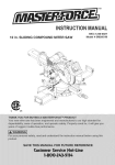
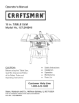
10 in. COMPOUND MITER SAW
Modem No. 137.212290
CAUTmON:
Before using this Mker Saw,
read this manual and follow
all its Safety Rules and
Operating Instructions
o
o
Safety mnstructions
mnstaliation
o
o
Operation
Maintenance
o
Parts List
Customer
Help Line
1 o800o843ol 682
Sears, Roebuck
Visit our Craftsman
and Co., Hoffman
website:
Part No. 137212290001
Estates,
www.sears.com/craftsman
IL 60179 USA
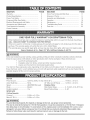
ONE-YEAR
FULL WARRANTY
ON CRAFTSMAN
TOOL
If this Craftsman tool fails due to a defect in material or workmanship within one year from the date of purchase,
CALL 1-800-4-MY-HOME ®TO ARRANGE FOR FREE REPAIR.
If this tool is used for commercial or rental purposes, this warranty will apply for only ninety days from the date of
purchase. This warranty applies only while this tool is in the United States.
This warranty gives you specific legal rights, and you may also have other rights, which vary, from state to state.
Sears,
Roebuck
& Co., Dept. 817 WA, Hoffman
Estates,
IL 60179
WARNmNG I
Some dust created by power sanding, sawing, grinding, drilling and other construction activities contains chemicals
known to cause cancer, birth defects or other reproductive harm. Some examples of these chemicals are:
, Lead from lead=based paints
CrystaI!ine silica from bricks, cement and other masonry products
Arsenic and chromium from chemically treated lumber
Your risk from these exposures varies, depending on how often you do this type of work. To reduce your exposure to
these chemicals, work in a well ventilated area and work with approved safety equipment such as dust masks that are
specially designed to filter out microscopic particle&
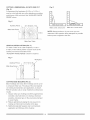
MOTOR
Power Source .......................... 120V AC, 60Hz, 15 Amp Beve! 45 ° L .............................. 1=9/16 in. x 5=1/2 in.
Arbor Shaft Size ...................... 5/8 in.
45 ° Miter and 45 ° Bevel .......... 1=9/16 in. x 3=1/2 in.
Speed ......................................
Brake .......................................
Double insulated .....................
MITER SAW
4800 RPM (No load)
Electric
Yes
Rotating Table:
Miter Detent Stops .................. 0, 15, 22.5, 31.6, 45 ° R & L
Bevel Positive Steps ............... 0, 45 °
Cutting Capacity:
Crosscut .................................. 2=5/8 in. x 5=1/2 in.
Miter 45 ° R & L ........................ 2=5/8 in. x 3=1/2 in.
1_, WARNING
I
To avoid electrical hazards, fire hazards or damage to the tool, use proper circuit protection°
This tool is wired at the factory for 110_120 Vott operation, it must be connected to a 110_120 Volt / 15 Ampere
time delay fuse or circuit breaker. To avoid shock or fire, reptace power cord immediately if it is worn, cut or
damaged in any way. Before using your too!, it is critical that you read and understand these safety rules.
Failure to follow these rules could result in serious injury to you or damage to the tool
GENERAL
BEFORE
SAFETY
mNSTRUCTmONS
USmNG THIS POWER
TOOL
Safety is a combination of common sense, staying alert
and knowing how to use your power tool.
l,&WARNING
n
To avoid mistakes that could cause serious injury, do not
plug the too! in unti! you have read and understood the
following.
1. READ and become fami{iar with the entire Operators
Manual. LEARN the tool's application, limitations and
possible hazards.
12.ALWAYS WEAR EYE PROTECTION Any power
too! can throw foreign objects into the eyes and
w_ _o_.
could cause permanent eye damage_
ALWAYS wear Safety Goggles (not
glasses) that comply with ANSI Safety
standard Z87.1 Everyday eyeglasses
have only impact-resistant lenses.
They ARE NOT safety glasses. Safety Goggles are
available at Sears. NOTE: Glasses or goggles not in
compliance with ANSI Z87.1 could seriously injure
you when they break.
1&WEAR A FACE MASK OR DUST MASK
operation produces dusL
Sawing
2. KEEP GUARDS tN PLACE and in working order.
14SECURE WORK. Use clamps or a vise to hold work
when practical. It's safer than using your hand and it
frees both hands to operate the tool
3. REMOVE ADJUSTING KEYS AND WRENCHES.
Form the habit of checking to see that keys and
adjusting wrenches are removed from the tool before
turning ON.
15DISCONNECT TOOLS FROM POWER SOURCE
before servicing, and when changing accessories
such as blades, bits and cutters.
4. KEEP WORK AREA CLEAN
benches invite accidents.
16REDUCE THE RiSK OF UNINTENTIONAL
STARTING. Make sure switch is in the OFF position
before plugging the too! in.
Cluttered areas and
5. DO NOT USE iN DANGEROUS ENVIRONMENTS.
Do not use power tools in damp locations, or expose
them to rain or snow. Keep work area well liL
6. KEEP CHILDREN AWAY. All visitors and bystanders
should be kept a safe distance from work area.
7. MAKE WORKSHOP CHILD PROOF with padlocks,
master switches or by removing starter keys.
8. DO NOT FORCE THE TOOL. It wil! do the job better
and safer at the rate for which it was designed.
9. USE THE RIGHT TOOL. Do not force the too! or an
attachment to do a job for which it was not designed.
10.USE PROPER EXTENSION CORDS. Make sure
your extension cord is in good condition. When
using an extension cord, be sure to use one heavy
enough to carry the current your product will draw.
An undersized cord win result in a drop in line voltage
and in loss of power which wil! cause the tool to
overheaL The table on page 5 shows the correct
size to use depending on cord length and nameplate
ampere rating, if in doubt, use the next heavier
gauge. The smaller the gauge number, the heavier
the cord.
11 .WEAR PROPER APPAREL Do not wear loose
clothing, gloves, neckties, rings, bracelets, or other
jewelry which may get caught in moving parts.
Nonslip footwear is recommended. Wear protective
hair covering to contain long hair.
17.USE RECOMMENDED ACCESSORIES. Consutt this
Operator's Manual for recommended accessories.
The use of improper accessories may cause risk of
injury to yourself or others.
18NEVER STAND ON THE TOOL. Serious injury
could occur if the too! is tipped or if the cutting tool is
unintentionally contacted_
1&CHECK FOR DAMAGED PARTS. Before further
use of the tool, a guard or other part that is damaged
should be carefully checked to determine that it will
operate properly and perform its intended function
= check for alignment of moving parts, binding of
moving parts, breakage of parts, mounting, and any
other conditions that may affect its operation. A guard
or other part that is damaged should be properly
repaired or replaced.
20NEVER LEAVE THE TOOL RUNNING
UNATTENDED. TURN THE POWER "OFF". Do not
walk away from a running tool until the blade comes
to a complete stop and the tool is unplugged from the
powe r sou roe.
21 DO NOT OVERREACH
balance at al! times.
Keep proper footing and
22.MA_NTAIN TOOLS W_TN CARE. Keep tools sharp
and clean for best and safest performance. Follow
instructions for lubricating and changing accessories.
2&WARNING: Dust generated from certain materials
can be hazardous to your health. Always operate
saw in well-ventilated area and provide for proper
dust removal.
SPECiFiC
SAFETY
THiS COMPOUND
mNSTRUCTmONS FOR
MINTER SAW
1. USE ONLY CROSS-CUTTiNG SAW BLADES.
When using carbide tipped blades, make sure they
have a negative hook angle.
IMPORTANT: DO NOT USE THIN KERF BLADESthey can deflect and contact guard and can cause
possible injury to the operator.
2. DO NOT operate the miter saw until it is completely
assembled and installed according to these
instructions.
3. tF YOU ARE NOT thoroughly familiar with the
operation of miter saws, seek guidance from your
supervisor, instructor, or other qualified person.
4. ALWAYS hold the work firmly against the fence and
table. DO NOT perform any operation free hand (use
clamp wherever possible).
5. KEEP BANDS out of the path of the saw blade. If
the workpiece you are cutting would cause your
hands to be within 6-3/4 inches of the saw blade, the
workpiece should be clamped in place before making
the cuL
6. BE SURE the blade is sharp runs freely and is free of
vibration.
7. ALLOW the motor to come up to ful! speed before
starting a cut.
8. KEEP THE MOTOR AIR SLOTS OLEAN and free of
chips or dust.
9. ALWAYS MAKE SURE all handles are tight before
cutting, even if the table is positioned in one of the
positive stops.
10.BE SURE both the blade and the co!lar are clean
and the arbor bolt is tightened securely.
11 .USE only blade collars specified for your saw.
18MAKE SURE the blade is not contacting the
workpiece before the switch is turned ON.
19.IMPORTANT: After completing the cut, release the
trigger and wait for the blade to stop before returning
the saw to the raised position.
20MAKE SURE the blade has come to a complete stop
before removing or securing the workpiece, changing
the workpiece angle, or changing the angle of the
blade.
21 .NEVER cut metals or masonry products with this
tool. This miter saw is designed for use on wood and
wood-like products.
22NEVER cut small pieces. If the workpiece being cut
would cause your hand or fingers to be within 6-3/4
inches of the saw blade the workpiece is too small
2&PROVIDE adequate support to the sides of the saw
table for long work pieces.
24NEVER use the miter saw in an area with flammable
liquids or gases.
25NEVER use solvents to clean plastic parts. Solvents
could possibly dissolve or otherwise damage the
material
26SHUT OFF the power before servicing or adjusting
the tool
27DISCONNECT the saw from the power source and
clean the machine when finished using.
28MAKE SURE the work area is clean before leaving
the machine.
29SHOULD any part of your miter saw be missing,
damaged, or fail in any way, or any electrical
component fail to perform properly, lock the switch
and remove the plug from the power supply outleL
Replace missing, damaged, or failed parts before
resuming operation.
12.NEVER use blades larger in diameter than 10 inches.
13.NEVER apply lubricants to the blade when it is
running.
14.ALWAYS check the blade for cracks or damage
before operation. Replace a cracked or damaged
blade immediately.
15.NEVER use blades recommended for operation at
less than 4800 RPM.
1&ALWAYS
al! times.
17NEVER
keep the blade guards in place and use at
reach around the saw blade.
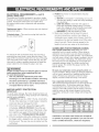
POWER SUPPLY AND MOTOR SPECIFICATIONS
The AC motor used in this saw is a universal,
nonreversible type. See "MOTOR" in the "PRODUCT
SPECIFICATIONS" section on page 2.
[A
WARNING]
To avoid electrical hazards, fire hazards, or damage to
the too!, use proper circuit protection. Your saw is wired
at the factory for 120V operation. Connect to a 120V,
15 Amp circuit and use a 15 amp. time delay fuse or
circuit breaker. To avoid shock or fire, if power cord is
worn or cut, or damaged in any way, have it replaced
immediately.
ELECTRICAL
REQUREMENTS
- cont'd
DOUBLE iNSULATED
The power tool is double insulated to provide a double
thickness of insulation between you and tool's electrical
system. All exposed metal parts are isolated from
the internal metal motor components with protecting
insulation.
Replacement parts = When servicing use only identical
replacement parts.
Polarized plugs = This saw has a plug that looks like
the one shown below:
4_ FUSES may "blow" or circuit breakers may trip
frequently if:
a. MOTOR is overloaded = overloading can occur if
you feed too rapidly or make too many start/stops
in a short time.
b. LiNE VOLTAGE is more than 10% above or
below the nameplate voltage rating. For heavy
loads, the voltage at motor terminals must equal
the voltage specified on the nameplate.
c. iMPROPER or duJl saw blades are used.
5. Most motor troubles may be traced to loose or
incorrect connections, overload, low voltage or
inadequate power supply wiring. Always check the
connections, the load and supply circuit if the motor
doesn't run well. Check minimum gauge for the
length of cord you are using on the chart below.
GUmDEUNES
To reduce the risk of electrical shock, this saw has a
polarized plug (one blade is wider than the other). This
plug wilt fit in a polarized outlet only one way. If the ptug
does not fit fully in the outlet, reverse the plug. If it still
does not fit, contact a qualified electrician to install the
proper outlet. Do not change the plug in any way.
la, WARNING
n
Double insulation does not take the place of normal
safety precautions when operating this tool.
To avoid electrocution:
1. Use only identical replacement parts when
servicing a toot with double insulation. Servicing
should be performed by a qualified technician.
2. Do not use power tools in wet or damp locations
or expose them to rain or snow.
MOTOR
SAFETY
PROTECTmON
iMPORTANT:
To avoid motor damage, the motor should be blown out
or vacuumed frequently to keep sawdust from interfering
with the motor ventilation.
1. CONNECT this saw to a 120V, 15 amp. circuit with a
15 amp. time delay fuse or circuit breaker. Using the
wrong size fuse can damage the motor.
2. If the motor won't start, release the trigger switch
immediately. UNPLUG THE SAW. Check the saw
blade to make sure it turns freely, if the blade is free,
try to start the saw again. If the motor still does not
start, refer to the "TROUBLESHOOTING
GUIDE"
3. If the too! suddenly statls while cutting wood, release
the trigger switch, unplug the tool, and free the blade
from the wood. The saw may now be started and the
cut finished
FOR EXTENSmON CORDS
Use a proper e×tenaion cord. Make sure your
extension cord is in good condition. When using an
extension cord, be sure to use one heavy enough to
carry the current your product will draw. An undersized
cord will cause a drop in line voltage, resulting in loss of
power and cause overheating. The table below shows
the correct size to use depending on cord length and
nameplate ampere rating. If in doubt, use the next
heavier gauge. The smaller the gauge number, the
heavier the cord.
Be sure your extension cord is properly wired and
in good condition. Always replace a damaged extension
cord or have it repaired by a qualified person before
using it. Protect your extension cords from sharp
objects, excessive heat and damp or wet areas.
Use a separate electrical circuit for your tools.
This circuit must not be less than # 12 wire and should
be protected with a 15 Amp time delay fuse. Before
connecting the tool to the power line, make sure the
switch is in the OFF position and the electric current is
rated the same as the current stamped on the motor
nameplate, running at a lower voltage will damage the
motor.
Ampere
MoreThan
0
6
!0
(When usng 120 volts only)
Rating
Total length of Cord
Not MoreThan 25fL
50ft.
100ft.
150ft.
6
8fL 16ft.
16fL
14ft.
10
8fL 16ft.
14ft.
12ft.
12
6ft. 16ft.
14ft.
12fL
CAUTION:
In aH cases
in question
is properly
have a certified
make
certain
grounded.
eJectrieian,
check
the receptacle
If you are not sure
the receptacle.
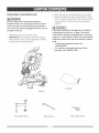
RECOMMENDED
ACCESSORIES
.)
IA WARNING
I
Use only accessories
recommended
miter saw. Foltow instructions that accompany
accessories. Use of improper accessories may
cause hazards.
,
The usa of any cutting
Blade Wrench (supplied)
Adjustable Wrench
Philips Screwdriver
Hex Key 2_5 mm
for this
too! except 10 inch saw
blades which meet the requirements under
recommended accessories is prohibited. Do
not use accessories such as shaper cutters or
,
dado sets. Ferrous metal cutting and the use of
abrasive wheels is prohibited,
Do not attempt to modify this toot or create
accessories not recommended for use with
Combination Square
COMBINATmON
SQUARE
this tool. Any such alteration or modification
is
misuse and could result in a hazardous condition
leading to possible
serious
injury.
Draw light line on board
along this edge.
ACCESSORmES
IA WARNING
I
perfectly straighL
/
injury, do not
modify this power tool or use accessories
recommended by Sears.
IA WARNING
Straight edge or
a 3/4 in. board,
this edge must be
\,
L
Visit your Sears Hardware Department or see the
Sears Power and Hand Tool Catalog to purchase
recommended accessories for this power tool
To avoid the risk of personal
MUST BE TRUE
not
!
I
Read warnings and conditions on your CARBIDE
TIPPED SAW BLADE. Do not operate the saw
without the proper saw blade guard in place.
Should not gap or overlap when
Carbide is a very hard but brittle material Care
should be taken while mounting, using, and storing
carbide tipped blades to prevent accidental damage.
Slight shocks, such as striking the tip while
handling, can seriously damage the blade. Foreign
objects in the workpiece, such as wire or nails, can
also cause tips to crack or break off. Before using,
always visually examine the blade and tips for bent
blade, cracks, breakage, missing or loose tips, or
other damage. Do not use if damage is suspected.
Failure to heed safety instructions and warnings
result in serious bodily injury.
can
square is flipped over (see
dotted figure).
UNPACKING
YOUR
MINTER SAW
2. Place the saw on a secure stationary work surface.
3. Separate ali parts from the packing material. Check
each one with the illustration to make certain all items
IA WARNING
n
To avoid injury from unexpected
starting
electrical shock, do not plug the power cord into a
source of power during unpacking and assembly.
This cord must remain unplugged whenever you are
working
[A& WARNING]
if any part is missing or damaged, do not attempt
to assemble the miter saw, or plug in the power
on the saw.
1. Remove the miter saw from the carton.
iMPORTANT:
are accounted for, before discarding any packing
material
or
Do not lift miter saw by the Trigger
Switch handle, it may cause misalignmenL Only lift
machine by the base Hand Hold&
cord until the missing or damaged part is correctly
replaced. To avoid etectric shock, use only identical
replacement parts when servicing douNe insulated
tools.
To purchase replacement
1-800-469-4683.
,
For missing
purchase,
or damaged
parts, call
parts upon initiat
caH 1-800-843-1882.
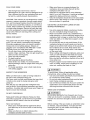
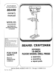
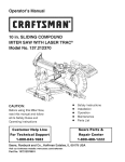
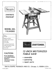
Dust Bag
Machine
Hold =Down Clamp
Blade Wrench
Miter Table Handle
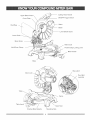
CuttingHeadHandle
UpperBladeGuard
CoverPlate
ON/OFFTriggerSwitch
Motor
DustBag
Blade
LowerBladeGuard
LaserGuide
BevelScale
MiterScale
Hold-Down
Clamp
PositiveStopLockingLever
MiterHandle
Base
Stop Latch
ArborLock
Pivot Bolt
Lock-Nut
\
Fence
Table Insert
/
Positive Miter Detents
Hand Hold
Mounting Hole
COMPOUND
MINTER SAW TERMS
ARBOR LOCK = Allows the user to keep the blade
from rotating while tightening or loosening the arbor bolt
during blade replacement or removal
WARNING LABELS = Read and understand for your
own safety. Make sure al! labels are present on machine
and legible.
WRENCH STORAGE = Convenient storage to prevent
misplacing the blade wrench.
BASE = Supports the table, holds accessories and
allows for workbench or leg set mounting.
WOODWORKING
TERMS
BEVEL LOCKING HANDLE = Locks the miter saw at a
desired bevel angle.
ARBOR = The shaft on which a blade is mounted.
BEVEL SCALE = To measure the bevel angle of the
saw blade 0 ° to 45 ° lefL
BEVEL CUT = An angle cut made through the face of
the workpiece.
COVER PLATE SCREW = Loosen this screw and rotate
COMPOUND
cut+
the plate for access to the blade arbor boll
CUT = A simultaneous bevel and miter
FENCE = Helps to keep the workpiece from moving
when sawing. Scaled to assist with accurate cutting.
CROSS CUT = A cut made across the width of the
HAND HOLD = For moving the saw when unplugged.
FREEHAND = Performing a cut without using a fence
(guide), hold down or other proper device to prevent the
workpiece from twisting during the cutting operation+
ON/OFF TRIGGER SWITCH = To start the tool,
squeeze the trigger. Release the trigger to turn off the
miter saw.
workpiece.
GUM = A sticky s-ap from wood products+
LOWER BLADE GUARD = Helps protect your hands
from the blade in the raised position, it retracts as the
blade is lowered.
HEEL = Misalignment of the blade.
MITER HANDLE = Use to lock and unlock the miter
MITER CUT = An angle cut made across the width of
the workpiece.
table, and to rotate the saw to a right or left cutting
position.
KERF = The amount of material removed by blade cut.
RESIN = A sticky sap that has hardened+
MITER SCALE = Measures the miter angle 0 ° to 45 ° left
and righL
REVOLUTIONS PER MINUTE (RPM} = The number of
turns completed by a spinning object in one minute.
POSJTtVE STOP LOCKING LEVER = With the miter
handle, locks the miter saw at a preset positive stop for
the desired miter angle.
MOUNTING HOLES = To mount the miter saw to a
stable surface.
STOP LATCH = Locks the miter saw in the lowered
SAW BLADE PATH = The area of the workpiece or
table top directly in line with the travel of the blade or the
part of the workpiece which will be cuL
SET = The distance between two saw blade tips, bent
outward in opposite directions to each other. The further
apart the tips are, the greater the seL
position for compact storage and transportation.
SWITCH HANDLE = The cutting head handle contains
the trigger switch. The blade is lowered into the
workpiece by pushing down on the handle. The saw will
return to its upright position when the handle is released.
WORKPtECE = The item being cuL The surfaces of a
workpiece are commonly referred to as faces, ends, and
edges.
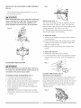
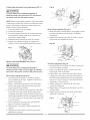
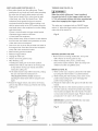
INSTALLING
THEMITERHANDLE(FIG.B)
1. Threadthemiterhandle(1)intothehole(2)located
atthefrontof themitertable.
Fig.D
Fig.B
Locking
When transporting or storing the miter saw, the cutting
head should always be locked in the down position.
4. Push the cutting head (3) down to its lowest position.
5. Push the stop latch (2) into the locking hole (4).
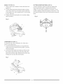
SAWBLADEWRENCH
(FIG.C)
1. Forconvenient
storageandprevention
ofloss,there
is a slot (1) in the rear of the cutting head handle (2)
for storing the blade wrench (3) when not in use.
IMPORTANT: To avoid damage, never carry the
miter saw by the switch handle, the cutting arm, or
the miter table handle.
Fig. C
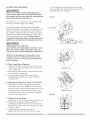
iNSTALLiNG THE DUST BAG (FIG. E)
1_ Squeeze the metal collar wings (2) of the dust
bag (1)_
2_ Place the dust bag neck opening around the exhaust
port (3), and release the metal collar wings.
Fig. E
CUTTING HEAD (FIG. D)
Raising
1. Push down slightly on the cutting handle (1).
2. Pull out the stop latch knob (2).
3. Allow the cutting head (3) to raise to the up position.
l,&WARNING
n
To avoid injury and damage to the saw, transport
or store the miter saw with the cutting head locked
in the down position. Never use the stop latch to
hold the cutting head in a down position for cutting
operations.
10
REMOVING
ORINSTALLING
THEBLADE
8. Remove the arbor bolt (4), outer blade collar (6), and
the blade (7). Do not remove the inner blade collar.
(Fig. G=2)
IA WARNING
n
Only use a 104rich diameter blade.
To avoid injury from an accidental start, make sure
NOTE: Pay attention to the pieces removed, noting their
the switch is in the OFF position and plug is not
connected to the power source outlet.
position and direction they face. Wipe the blade collars
clean of any sawdust before installing the new blade.
REMOWNG (FIG. G, G-l, G-2}
1. Unplug the saw from the outleL
2. Allow the miter saw to rise to the upright position.
Raise the lower blade guard (1) to the up position.
Fig. G-2
6
(Fig. G)
3. Loosen the cover plate screw (2) with a Phillips
screwdriver.
4. Rotate the cover plate (3) towards the rear of the tool
to expose the arbor bolt (4).
5. Place the blade wrench over the arbor bolt.
Fig. G
7
6
1
tNSTALUNG THE BLADE (FIG. G, G-I, G-2}
1. install a 10 in. blade, making sure the rotation arrow
on the blade matches the clockwise rotation arrow on
the upper guard, and the blade teeth are pointing
downward.
2. Place the outer blade collar (6) against the blade and
on the arbor. Thread the arbor bolt (4) into the arbor
counterclockwise. (Fig. G-2)
IMPORTANT:
Make sure the fiats of the blade collars
are engaged with the fiats on the arbor shall
3. Place the blade wrench on the arbor boll
6. Locate the arbor lock (5) on the motor, below the
miter saw switch handle. (Fig. G-1 )
7. Press the arbor lock, holding it in firmly while turning
the blade wrench clockwise. The arbor lock wi!l
4. Press the arbor lock (5), holding it in firmly while
turning the blade wrench counterclockwise. When
it engages, continue to press the arbor lock in,
while tightening the arbor bolt securely. (Fig. F)
5. Rotate the cover plate (3) back until the slot in the
cover plate engages with the cover plate screw
engage after turning the wrench. Continue to hold
the arbor lock in to keep it engaged, while turning
the wrench clockwise to loosen the arbor boll
(2). Tighten the screw with a Phillips screwdriver.
Lower the blade guard.
6. Be sure the arbor lock is released so the blade
Fig. G-1
turns freely.
[,&wARN Ne]
,
To avoid injury, never use the saw without the
cover plate secure in place. It keeps the arbor
bolt from falling out if it accidentally loosens, and
helps prevent the spinning blade from coming off
the saw.
Make sure the collars are clean and properly
arranged. Lower the blade into the table and
check for any contact with the metal base or the
turn table.
11
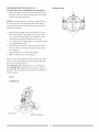
iNSTALLiNG
THEHOLD-DOWN
CLAMPASSEMBLY
(FIG.H)
1_Placethehold=down
clampassembly(1)in one
2
Fig.t
1
of
the mounting holes (2)_
IA WARN,NG
n
/
When using stop block on the right side, hold-down
clamp must also be in right side. Using hold-down
clamp on the left side during this operation can
cause kickback and serious injury to the operator.
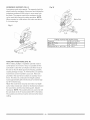
MITER SCALE (FIG. J)
The miter scale assists the user in setting the desired
miter angles from 47 ° left to 47 ° right. The miter saw
table has nine of the most common angle setttings with
Fig. H
positive stops at 0 °, 15 °, 22.5 °, 31 _6°, and
45 °. These positive stops position the blade at the
desired angle quickly and accurately.
To Adjust the Angle:
1
1. Unlock the miter table by turning the miter handle (1)
counterc!ockwise.
2
2. Press down the positive stop locking lever (2) while
holding the miter handle, and rotate the table left or
2
right to the desired angle.
3. Release positive stop locking lever. Tighten miter
handle.
To Adjust the Indicator:
I. Position the miter table at zero degrees.
2. Loosen the pointer screw (4) and adjust the indicator
to the 0 ° mark on the miter scale and retighten the
ADJUSTMENT
iNSTRUCTiONS
screw.
5
Fig. J
3
2
l_ WARN"NG
n
To avoid injury from an accidental start, make sure
the switch is in the OFF position and the plug is not
connected to the power source outlet.
CUTTING ARM TRAVEL (FIG. K)
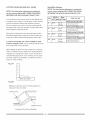
ADJUSTING FENCE SQUARENESS (FIG. 0
1. Loosen the four fence locking bolts (1).
2_ Lower the cutting arm and lock in position.
Cutting arm pivot adjustment
The up and down pivot movement of the cutting arm (1)
should not be too tight, restricting movement, nor too
3_ Using a square, lay the heel of the square against the
blade, and the rule against the fence (2) as shown.
Check to see if the fence is 90 ° to the blade.
loose, affecting the accuracy of the saw cut. The correct
locking nut (2) adjustment is snug, allowing no side-toside arm movement. To adjust, tighten or loosen the
adjusting nut (2).
4_ If not, adjust fence 90 ° to the blade and tighten the
fence locking bolts.
CAUTION: If the saw has not been used recently,
recheck blade squareness to the fence and readjust
if needed.
Fig. K
4
12
Cutting head downward
travel adjustment
(FIG. L)
Fig. M
IA WARNING
I
To avoid injury from unexpected starting or
electrical shock, turn the switch OFF and remove
3
the power cord from the power source.
72
NOTE: Before each cutting operation, check the position
of the blade to make sure it does not contact any metal
surface. If the blade contacts any metal surface, the
depth of trave! must be adjusted.
1. Lower the blade as far as possible.
90°(0 °) Bevel indicator (Fig. M-I )
2. Loosen the Iocknut (3).
3. Turn the adjustment balt (4) out (counterclockwise)
1. When the blade is exactly 900(0°) to the table, loosen
the bevel indicator screw (5) using a #2 Phi!lips
screwdriver.
to decrease the cutting depth or in (clockwise) to
increase the cutting depth.
4. Rotate the blade manually to check for contacL
2. Adjust bevel indicator (6) to the "0" mark (7) on the
bevel scale and retighten the screw.
5. Repeat until adjusted properly, and tighten the
!ocknut to secure the adjustment bolt into position.
Fig. M-l
4
Fig. L
3
BEVEL STOP ADJUSTMENT
(FIG. M & N)
45 ° Bevel adjustment (Fig. N)
1. Unlock the beve! lock handle and tilt the cutting arm
as far to the left as possible.
WARNING
I
To avoid injury from unexpected
starting
or
electrical shock, make sure the trigger is released
and remove the power cord from the power source.
2. Using a combination square, check to see if the
blade angle is 45 ° to the table.
3. If the blade is not at 45 ° to the miter table, tilt the
90°(0 °) Bevel adjustment (Fig. M)
1. Loosen bevel lock handle (1) and tilt the cutting
arm completely to the right. Tighten the bevel lock
handle. Lower blade.
cutting arm to the right, loosen the jamb nut (5) on
the bevel angle adjustment bolt (4) and adjust the
bolt (4) in or out to increase or decrease the bevel
angle with a 10 mm wrench.
2. Place a combination square (2) on the miter table
with the rule against the table and the hee! of the
square against the saw blade.
4. Tilt the cutting arm to the left to 45 ° bevel and
recheck for alignment.
5. Repeat steps 1 through 4 until the blade is at 45 ° to
the miter table.
3. If the blade is not 900(0 °) square with the miter table,
loosen the bevel lock handle, tilt the cutting head
completely to the left, loosen the jamb nut (4) on the
bevel angle adjustment bait (3) and adjust the bolt (3)
6. Tighten bevel lock handle and jamb nut (5) when
alignment is achieved.
5
in or out to increase or decrease the bevel angle with
a 10 mm wrench.
4. Tilt the cutting arm to back to the right at 900(0 °)
bevel and recheck for alignment.
5. Repeat steps 1 through 4 if further adjustment is
needed.
Fig. N
6. Tighten bevel lock handle and jamb nut (4) when
alignment is achieved.
13
ALiGNiNGTHELASER
BEAM
(1)_ Start with the set screw on the left side of the
laser assembly, then with the front set screw on the
right side of the laser assembly.
[A WARNING
[
For your own safety, never connect the plug to
power source outlet unti[ all the adjustment steps
are complete and you have read and understood the
safety and operational instructions.
Fig. N-1
The laser beam must always be correctly aligned with
the blade to ensure straight, even cutting.
Your tool is equipped with the Laser Trac® cutting
guide using Class ilia laser beams. The laser beam wilI
enable to preview the saw blade path on the stock to
be cut before starting the miter saw. This laser guide is
powered by the transformed alternating current supply
directly through the power lea& The saw must be
connected to the power source and the laser on/off
switch must be turned on for the laser line to show.
Laser
"
Switch
'i
i_
wARN Ne
I
AVOID DIRECT EYE CONTACT
Loser radiated when [aser guide is turned oil. Avoid
direct eye contact° Always un-piug the miter saw
from power source before making any adjustments.
NOTE: All the adjustments
for the operation of this
machine have been completed
at the factory. Due to
normal wear and use, some occasional
readjustments
may be necessary.
A. Check Loser Beam Alignment.
1. Mark a 90 ° straight line across a board to serve as a
"pattern line" to test laser alignment. Lay the board
on the miter table.
2. Plug saw into outlet and turn on the laser beam and
line it up with the pattern line.
3. Lower saw blade to pattern line and if blade is
not flush with the pattern line, adjust as follows in
procedures (B).
B. Adjusting
Left Side View
the Angle of the Laser Trac®(Fig. N-2)
1. Turn the laser element (1) in the desired direction
to adjust the laser angle. NOTE: Do not adjust the
laser more than _Aturn in either direction as this may
damage the laser. There are two flat sides on the
Right Side View
laser element where you can position an adjustable
wrench for your adjustment.
Fig. N-2
C. Aligning The Laser Beam
1. Loosen only Y2turn at a time the three set screws (1).
2. Adjust laser by turning the left side set screw
clockwise to shift the laser line to the right. To shift
the laser line to the left, turn the right side set screws
_/2turn at a time.
3. Once alignment of the laser is achieved,
tighten only Y2turn at a time the three set screws
14
MOUNTING THE MITER SAW (FIG, O)
To avoid injury from unexpected mew movement:
,
Stationery
Before moving the saw, disconnect the power cord
from the outlet, and !ock the cutting arm in the lower
position using the stop latch.
NOTE: The stop latch is for carrying or storing the tooL
It is not to be used for holding the saw while cutting.
Lower blade and press in stop latch to secure saw for
transport or storage.
Never carry the miter saw by the power cord or by
the switch handle. Carrying the tool by the power
cord could cause damage to the insulation or wire
connections resulting in electric shock or fire.
To avoid injury from flying debris, do not allow visitors
to stand behind the saw.
Place the saw on a firm, level work-surface where
there is room for handling and properly supporting
the workpiece.
Support the saw on a leve! work surface.
Bolt or clamp the saw to its support.
Place the saw in the desired location, either on a work
bench or recommended leg seL The base of the saw
has three mounting holes (1).
For etetionery use, fasten the saw to a workbench.
For po_ebte uee, fasten the saw to a 3/4 in. piece of
plywood. This mounting board can then be clamped to a
secure surface.
Fig. 0
Portable Use
Hand Hold
3/4 Inch Plywood
15
Uee
SAFETY mNSTRUCTmONS FOR BASmC SAW
OPERATmON
BEFORE USING THE MITER SAW
,
IAWARNING
n
To avoid mistakes thatcould cause serious,
permanent injury, do not plug the toolin until the
following steps are completed:
, Completely assemble and adjust the sew,
following the instructions. (ASSEMBLY AND
ADJUSTMENTS)
, Learn the use and function of the ON/OFF switch,
lock-off switch, upper and lower blade guards,
stop latch, bevel lock handle, end cover plate
,
USE ONLY RECOMMENDED
Consult the ACCESSORIES
screws.
,
,
,
Review and understand all safety instructions
and operating procedures in this Operator's
Manual (SAFETY & OPERATIONS)
Reviewthe MAINTENANCE and
TROUBLESHOOTING GUIDE for your miter saw.
To avoid injury or possible death from etectricaJ
shock:
,
and ATTACHMENTS
instructions that come with the accessory. The
use of improper accessories may cause risk of
injury to persons.
Choose the correct 10 inch diameter blade for the
material and the type of cutting
Do not use thin kerf blades.
,
BEFORE EACH USE INSPECT YOUR SAW.
,
,
,
ACCESSORIES
section of this Operators Manual for
recommended accessories. Follow the
Make sure your fingers do not touch the plug's
metal prongs when plugging or unplugging your
miter saw. (ELECTRICAL REQUIREMENTS AND
SAFETY)
,
is missing, bent damaged or broken in any way,
or any electrical parts don't work, turn the saw
off and unplug it. Replace damaged, missing, or
defective parts before using the saw again.
Maintain tools with care. Keep the miter saw
clean for best and safest performance. Follow
instructions for lubricating. Don't put lubricants
on the blade while it's spinning.
Remove adjusting wrench from the tool before
turning it on.
To avoid injury from jams, slips, or thrown
pieces:
Disconnect the miter saw. To avoid injury from
accidental starting, unplug the saw before any
adjustments, including set-up and blade changes.
Compare the direction of rotation arrow on the
guard to the direction arrow on the blade. The
blade teeth should always point downward st the
front of the saw.
you plan to do.
Make sure the blade is sharp, undamaged
properly aligned. With the saw unplugged,
the cutting arm sH the way down. Manually
the blade and check for clearance. Tilt the
head to s 45 ° bevel and repeat the test.
Make sure the btede and arbor collars are
and
push
spin
powerclean.
Make sure all clamps and !ocks ere tight and
there is no excessive play in any parts.
KEEPYOUR
Cluttered
WORK AREA CLEAN
areas and
[J& WARNING
Tighten the arbor bolt.
Tighten the cover plate screw.
Check for damaged parts. Check for:
Alignment of moving psAs
Damaged electric cords
Binding of moving parts
, Mounting holes
, Function of arm return spring and lower
guard:
Push the cutting arm all the way down, then
let it rise until it stops. The lower guard
should fully ctose. Follow instructions in
TROUBLESHOOTING
GUIDE for adjustment if
necessary.
, Other conditions that may affect the way the
miter saw works.
benches
invite accidents.
1
To avoid burns or other fire damage, never use the
miter saw near fmsmmsble Hquids, vapors, or gases.
Plan ahead to protect your eyes, hands, face end
esrs.
,
,
Keep all guards in place, in working order and
proper adjustment. If any part of this miter saw
16
Know your miter saw.
Read and understand the Operator's Manual and
labels affixed to the tool Learn its application
and limitations as wen as the specific potential
hazards peculiar to this tool. To avoid injury from
eccidentsJ contact with moving parts, don't do
layout, assembly, or setup work on the miter saw
while any parts are moving.
Avoid accidental starting
Make sure the trigger switch is disengaged
before plugging the miter saw into e power outtet.
PLANYOURWORK
Make sure there ere no gaps between the
workpiece, fence end table that will let the
workpiece shift after it is cut.
Keep the cut off piece free to move sideways
after it is cut off. Otherwise, it could get wedged
against the blade end thrown violently.
Only the workpiece should be on the saws table.
Secure work. Use ctemps or a vise to help hotd
the work when it's practical.
Usethe righttool. Don'tforcea tool or
attachmentto do e job it was not designed
to do.
Use a different tool for any workpiece that can't
be held in e solidly braced, fixed position.
CAUTION: This machine is not designed for cutting
masonry, masonry products, ferrous metals (stee!,
iron, and ironobesed metals°) Use this miter sew to
cut only wood, wood-like products, or non-ferrous
metals. Other materiel may shatter, bind the blade,
or create other dangers. Remove aH nails that may
be in the workpiece to prevent sparking that could
cause a fire. Remove dust beg when cutting non °
ferrous metals.
USE EXTRA CAUTION WITH LARGE OR ODD
SHAPED WORKPIECES.
DRESS FOR SAFETY
Any power tool can throw foreign objects into the
eyes. This can result in permanent eye damage.
Everyday eyeglasses have only impact resistent
lenses and ere not safety glasses. Glasses or
goggtes not in compliance with ANSI Z87.1 could
seriously injure you when they break.
, Do not wear loose clothing, gloves, neckties or
jewelry (rings, watches)° They con get caught and
draw you into moving parts.
• Wear non-stip footwear.
, Tie back long heir.
• Roll tong sleeves above the elbow.
• Noise levels very widety. To avoid possible
hearing damage, wear ear plugs when using any
miter sew.
, For dusty operations,wear e dust mask along
with safety goggles.
iNSPECTYOUR
•
Use extra supports (tables, sawhorses, blocks,
etc.) for workpieces large enough to tip.
Never use another person as e substitute for e
table extension, or as an additional support for e
workpiece that is longer or wider then the basic
miter saw table, or to help feed, support, or pull
the workpiece.
Do not use this sew to cut sina!! pieces. If the
workpiece being cut would cause your hand or
fingers to be within 6-3/4 inches of the saw blade
the workpiece is too smell. Keep hands end
fingers out of the "no hands zone" area marked
on the saws table.
When cutting odd shaped workpieces, plan your
work so it will not bind in the blade end cause
possible injury. Molding, for example, must He
fiat or be hetd by e fixture or jig that will not let it
move when cut.
Properly support round materia_ such as dowel
rods, or tubing, which have e tendency to roll
when cut, causing the blade to "bite".
[J_ WARNING
WORKPtECE
1
To avoid injury, follow all applicable safety
instructions, when cutting non-ferrous metals:
Use only sew blades specifically recommended
for non-ferrous meteJ cutting.
Do not cut metal workpieces that must be hand
held. C!amp workpieces securely.
Cut non4errous metals onty if you are under the
supervision of an experienced person end the
dust beg has been removed from the sew.
Make sure there ere no nails or foreign objects in
the part of the workpiece being cut.
Plan your work to avoid smetl pieces that may bind,
or that are too small to clamp and get a solid
grasp on.
Plan the way you witl grasp the workpiece from
startto finish.
Avoid awkward operationsend hand
positions.
A sudden slipcould cause your fingersor
hand to move into the blade.
WHEN SAW iS RUNNING
DO NOT OVER-REACH
[AWARNmNG]
Keep good footing end balance.
Keep your face
and body to one side, out of the line of e possible
kickback.
NEVER stand in the line of the blade.
Do not eilow familiarity from frequent use of your
miter sew to result in e careless mistake. A careless
fraction of e second is enough to cause e severe
injury.
Never cut freehand:
Brace your workpiece firmly against the fence
end table stop so it will not rock or twist during
the cut.
• Make sure there is no debris between the
workpiece and the table or fence.
Before cutting, if the sew makes an unfamiliar noise
or vibrates, stop immediately. Turn the sew OFF.
Unplug the saw. Do not restart until finding and
correcting the problem.
17
BODYANDBANDPOSITION
(FIG.P}
Neverplacehandsnearthecuttingarea.Proper
positioning
of yourbodyandhandswhenoperating
themitersawwillmakecuttingeasierandsafer.
Placehandatleast6=3/4in. away from the path
TURNING SAW ON (FIG. Q}
[A wARNINe]
Make the switch child-proof.
Insert e psdloek
through the hole (2} in the trigger switch and lock
of the blade, out of the "No=Bands Zone." Bold
it. This will prevent children and other unauthorized
users from engsging the trigger switch ON.
workpiece firmly against the fence to prevent
movement toward the blade. Before making a cut,
with the power switch in the OFF position bring the
saw blade down to the workpiece to see the cutting
path of the blade.
Press in lock=off switch in trigger switch handle.
This miter saw is equipped with an ON/OFF trigger
switch (1). When the trigger switch is squeezed, the
miter saw wil! be turned on.
Squeeze trigger switch to start saw.
Lower blade into workpiece.
Fig. Q
2
1
Keep children away. Keep all visitors a safe distance
from the miter saw. Make sure bystanders are clear
of the miter saw and workpiece.
Don't force too!. It will do the job better and safer at
its designed rate. Feed the saw into the workpiece
slowly with a firm downward motion.
Before freeing jammed materia!.
BEFORE LEAWNG THE SAW
Release Trigger Switch.
Unplug the miter saw.
Wait for atl moving parts to stop.
, Never leave too! running unattended. Turn power
OFF. Wait for alt moving parts to stop.
After finishing a cut:
Holding the cutting arm in the down position.
Release the switch, and wait for al! moving parts
to stop before moving your hands and before
Make workshop child- proof. Lock the shop.
Disconnect master switches. Store tool away from
children and other unqualified users.
raising the cutting arm.
If the blade doesn't stop within 6 seconds, unplug
the saw and follow the instructions in
TROUBLESHOOTING GUIDE section for
MITER CUT (FIG. R)
1. When s miter cut is required, unlock the miter table
by turning the miter handle (1) counterclockwise.
2. While holding the miter handle, press down on the
positive stop locking lever (2) to disengage the
positive stop locking lever.
adjusting the blade brake before using the saw
again.
, Release the trigger switch, and wait for a!l moving
parts to stop before moving your hands and raising
cutting arm.
3. Rotate the miter table to the right or left with the miter
handle.
4. When the table is in the desired position as shown on
the miter scale (3), release the positive stop locking
Fig. P
lever handle and tighten the miter handle. The table
is now locked at the desired angle. Positive stops are
provided at 0°,15 ° , 22.5 ° , 31.6 ° and 45 °.
IMPORTANT:
ALWAYS TIGHTEN the miter table
lock handle before cutting.
Fig. R
®
6o3/4 in.
®
, ,,
,
6o3/4 in.
I
18
BEVELCUT(FIG,S)
1_Whena bevelcutis required,loosenthebevelIock
handle(1)_
2_Tiltthecuttingheadtothedesiredangleasshown
onthebevelscale(2).Thebladecanbepositioned
atanyangle,froma 90° straightcut(0°onthescale)
toa 45° leftbevel.
& Tightenthebevellockhandle(1)tolockthecutting
headin position_
CUTTINGBOWEDMATERIAL(FIG.U)
A bowedworkpiece
mustbepositioned
againstthe
fenceandsecuredwitha clampingdevicebefore
cutting.Donotpositionworkpiece
incorrectly
or tryto
cuttheworkpiece
withoutthesupportofthefence.This
wilIcausethebladetobindandcouldresultin personal
injury.
Fig.U
Fig.S
2
1
COMPOUND
CUT(FIG,T)
A compound
cutisthecombination
ofa miteranda
bevelcutsimultaneously.
1_Loosenthebevellockhandle(1)andpositionthe
cuttingheadatthedesiredbevelposition_
Lockthe
bevellockhandle.
2_ Loosenthe mitertablelockhandle(2)_Pressdown
thepositivestoplockinglever(3)andpositionthe
tableatthedesiredangle.Releasethepositivestop
lockingleverandlockthemiterhandle_
Fig.T
3
2
19
WORKPtECE
SUPPORT
(FIG.V)
Longpiecesneedextrasupport.Thesupportshouldbe
placedundertheworkplece.
Keepyourhandholdingthe
workpiecepositioned
6-3/4inchesor moreawayfrom
theblade.Thesupportmustlettheworkp+ece
layflat
ontheworktableduringthecuttingoperation.
NOTE:
Whenmountedona flatsurface,themitersawtableis
3-1/4incheshigh.
Fig+W
/
i
[
[
Blade Slot
Fig+V
\
Cutting capacity with auxiliary fence
Crosscut
3ol/2 in. x 3-1/2 in.
Miter 45 ° R & L
3-1/2 in. x 2 in.
Bevel 45 ° L
2 in. x 3-1/2 in.
Compound 45 °L,45 °R&L
2in. x2in.
3-1/4 in.
AUXILARY
WOOD FENCE (FIG. W)
When making multiple or repetitive cuts that result in
cut-off pieces of one inch or less, it is possible for the
saw blade to catch the cut-off piece and throw it out of
the saw or into the blade guard and housing, possibly
causing damage or injury. To minimize this, an auxiliary
wood fence can be mounted to your saw. Holes are
provided in the saw fence to attach an auxiliary wood
fence. This fence is constructed of straight auxiliary
wood approximately 3/4 inch thick by 2-1/2 inches high
by 16-1/8 inches long.
Attach the wood fence securely and make a full depth
cut to make a blade slot. Check for interference between
the wood fence and the lower blade guard. Adjust if
necessary. NOTE: This auxiliary fence is used only with
the saw blade in the 0 ° bevel position (90 ° to the table).
The auxiliary wood fence must be removed when bevel
cutting.
2O
CUTTING
A BIJ"_ENSIONAL
4X4WITHONECUT
(Fig.X)
Fig. Z
A dimensional 4x4 workpiece (3ol/2 in_ x 3ol/2 in_ )
may be cut in half with one cut by attaching an auxiliary
wood fence of 3/4 inch thick. See "AUXILIARY WOOD
FENCE" above.
FI
Fm
em
nl
cm
el
Fig. X
Auxiliary Fence \
Miter Saw Fenc
_
3-1/2 in.
/ ' _ __._ti
Miter Saw Table
Miter Sa_v Table
Miter at 45 °, bevel at 0°
Miter at 0 °, bevel at 45 °
NOTE: Always perform a dry run cut so you can
determine if the operation being attempted is possible
before power is applied to the saw.
L
I
Miter Saw Table
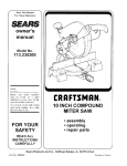
VERTICAL MITER CUTTING (FIG. Y}
To make a miter cut in a 2x4 workpiece (1-1/2in. x
3-1/2in.) in the vertical position a spacer such as the
auxiliary wood fence described in the
"AUXILIARY WOOD FENCE" section is required.
Fig. Y
Workpiece
1ol/2 in. _
Auxiliary Fenc_b,_
3ol/2 in_
Miter Saw Fen_
---,
Ii
1
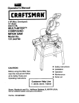
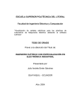
CUTTING BASE MOLDING (FIG. Z}
Base moldings and many other moldings can be cut on
a compound miter saw. The setup of the saw depends
on molding characteristics and application, as shown.
Perform practice cuts on scrap material to achieve best
results:
1. Always make sure moldings rest firmly against fence
and table. Use hold-down or C-clamps, whenever
possible, and place tape on the area being clamped
to avoid marks.
2. Reduce splintering by taping the cut area prior to
making cut. Mark cut line directly on the tape.
3. Splintering typically happens due to wrong blade
application and thinness of the material
21
CUTTING
CROWNMOLDING
(FIG.
AA,BB)
NOTE: The chart below references s compound
cut for crown motding ONLY WHEN THE ANGLE
BETWEEN THE WALLS EQUALS EXACTLY 90 °.
Your compound miter saw is suited for the difficult task
of cutting crown molding. To fit properly, crown molding
must be compound=mitered with extreme accuracy.
The two surfaces on a piece of crown molding that fit
fiat against the ceiling and wall are at angles that, when
added together equal exactly 90°.
Bevel/Miter
Settings
NOTE: The chart below references s compound
cut for crown molding ONLY WHEN THE ANGLE
BETWEEN THE WALLS EQUALS EXACTLY 90 °.
KEY
BEVEL
SETTING
Miter
,SETTING
TYPE OF CUT
I
inside corner-Left
33.9 °
R1.6 °
ight
3&9 °
31.6 °
Left
Miter tame set at RIGHT 31 6<
ositionside
topis offinished
molding piece
against fence
LEFT
L
hside
IR
side
corner-Right
3 LEFT side is finished
piece
Outside corner-Left
Most crown molding has a top rear angle (the section
that fits fiat against the ceiling) of 52°and a bottom rear
angle (the section that fits fiat against the wall) of 38°.
tn order to accurately cut crown molding for s 90 °
inside or outside corner, lay the molding with its broad
back surface fiat on the saw table.
When setting the bevel and miter angles for compound
miters, remember that the settings are interdependent;
changing one changes the other, as well Also keep in
mind that the angles from crown molding are very easy
for these angles to shift slightly, al! settings should be
tested on scrap molding.
Fig. AA
FI
em
nl
cl
em
Miter Saw Table
Fig. BB
Settings for standard crown molding lying fiat on
compound miter saw table
Inside Corner
Outside Corner
Compound Cut Crown Moldings
OL
3&9 °
31.6 °
Left
OR
J3&9°
side
Position
bottom
molding
against fence
Miter
table
set atofLEFT
31 6°
3 RIGHT side is firlished
piece
Outside corner-Right
R1-6 °
_ght
side
Position
bottom
molding
against fence
Miter
tame
set atofLEFT
31 6°
Eli
side
Miter table set at RIGHT 31 6'
osition top of molding against fence
RIGHT sk_e is finished piece
MAINTENANCE
protection. Should the lower guard become damaged,
do not use the saw until the damaged guard has been
replaced. Develop s regular check to make sure the
lower guard is working properly. Clean the lower guard
of any dust or buildup with a damp cloth.
IA DA"GERn
Never put lubricants
spinning.
on the blade while it is
IAWARNING
n
CAUTION: Do not use solvents on the guard. They
could make the plastic "cloudy" and brittle.
To avoid fire or toxic reaction, never use gasoline,
naphtha acetone, lacquer thinner or similar highly
vo!stile solvents to clean the miter saw.
WARNING]
When ctesning the lower guard, unplug the saw from
the power source receptacle to avoid unexpected
startup.
IAWARNmNG
H
To avoid injuryfrom unexpected startingor
electrical shock, unplug the power cord before
working on the saw.
SAWDUST
Periodically, sawdust will accumulate under the work
table and base. Frequently blow out or vacuum up the
sawdusL
IAwAR.I.G
n
For your safety,thissaw isdouble-insulated.
To
avoid electrical shock, fire or injury, use only
parts identical to those identified in the parts list°
Reassemble exactly as the original assembly to
avoid electrical shock.
[,& WARNING]
ff btowing sawdust, wear proper eye protection
keep debris from blowing into eyes.
to
LUBRICATmON
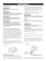
REPLACING CARBON BRUSHES (FIG. CO)
Replace both carbon brushes when either has less
than 1/4in. length of carbon remaining, or if the spring
or wire is damaged or burned. To inspect or replace
brushes, first unplug the saw. Then remove the black
plastic cap (1) on the side of the motor (2). Remove the
cap cautiously, because it is springloaded. Then pull
out the brush and replace. Replace for the other side.
To reassemble reverse the procedure. The ears on
the metal end of the assembly go in the same hole the
carbon part fits into. Tighten the cap snugly, but do not
overtighten.
Atl the motor bearings in this tool are lubricated with a
sufficient amount of high grade lubricant for the life of
the unit under normal operating conditions; therefore, no
further lubrication is required.
Lubricate the following as necessary:
Chop pivot: Apply light machine off to points indicated in
illustration.
Central pivot of plastic guard: Use light household oil
(sewing machine off ) on metal=to=metal or metal=to=
plastic guard contact areas as required for smooth, quiet
operation. Avoid excessive off, to which sawdust will
cling.
NOTE: To reinsta!l the same brushes, first make sure
the brushes go back in the way they came out. This wil!
avoid s break-in period that reduces motor performance
and increases wear.
Fig. DD
2
Fig. CO
Add oil here
1
4
Add oilhere ....... I
and on
_
opposide side _
LOWER
BLADE
GUARD
Do not use the saw without the lower blade guard.
The lower blade guard is attached to the saw for your
23
IA WARNING
n
To avoidinjury
from accidental
starting,
alwaysturnswitchOFF and unplugthetoolbeforemoving,replacing
theblade
or making adjustments_
Consult your Sears Service Centre if for any reason the motor wi!! not run.
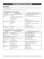
TROUBLESHOOTING
GUIDE o MOTOR
PROBLEM
Brake does not
stop blade within 6
seconds.
PROBLEM CAUSE
SUGGESTED
1. Motor brushes not sealed or lightly
sticking.
2. Motor brake overheated from use of
defective or wrong size blade or rapid
ON/OFF cycling.
3. Arbor bolt loose.
4. Other.
Motor does not start 1. Fuse Blown
PROBLEM
Blade hits table.
3. Retighten.
4. Sears Service Centre.
2. Replace brushes. See MAINTENANCE
section.
3. Sears Service Centre.
1. Brush worn.
2. Other.
TROUBLESHOOTING
1_ inspect / clean / replace brushes_ See
MAINTENANCE section.
2. Use a recommended blade. Let cool down.
1. Check and use15-Amp time delay fuse, or
circuit breaker.
2. Brush worn.
3. Other.
Brush spark when
switch released.
CORRECTIVE ACTION
1. Replace Brushes.
2. See Sears Service Centre.
GUIDE o SAW OPERATION
PROBLEM CAUSE
SUGGESTED
1. MisalignmenL
CORRECTIVE ACTION
1. See ADJUSTMENT
section.
Angle of cut not
1. Miter table unlocked.
accurate.
2. Sawdust under table.
Can't adjust miter.
Cutting arm wobbles. 1. Loose pivot points.
1. See OPERATION Section.
2. Vacuum or blow out dust,
WEAR EYE PROTECTION.
1. See ADJUSTMENT Section.
Cutting arm won't
fully raise, or blade
1. Part failure.
2. Pivot spring not replaced properly
1. Sears Service Centre.
2. Sears Service Centre.
guard won't fully
close.
after service.
3. Sawdust build=up.
3. Clean and lubricate moving parts.
Blade binds, jams,
1. Improper operation.
1. See BASIC SAW OPERATION section.
burns wood.
2. Dull blade.
3. improper blade size.
4. Warped blade.
2. Replace or sharpen blade.
3. Replace with 10in. diameter blade.
4. Replace blade.
Saw vibrates or
shakes.
1. Saw blade not round.
2. Saw blade damaged.
1. Replace blade.
2. Replace blade.
3. Saw blade loose.
4. Other.
3. Tighten arbor bolt.
4. Sears Service Centre.
24
10 in. COMPOUND
MITER SAW
MODEL
NO. 137.212290
IA WAR"I"G
n
When servicing use only CRAFTSMAN
replacement parts. Use of any other parts many create a HAZARD or cause
product damage. Any attempt to repair or replace electrical parts on this Miter Saw may create a HAZARD unless
repair is done by a qualified service technician. Repair service is available at your nearest Sears Service Centre.
To purchase replacement parts, call 1°800°469°4663.
PARTS LIST FOR SAW SCHEMATIC
I,D.
NO
DESCRIPTION
SiZE
DESCRIPTION
SIZE
OKRO
NUT
M12_1.75
0KUY
TERMINAL
0LS9
ROCKER
0LU2
LIMIT
0QQ1
GUARD-CORD
0S1S
COLLAR
128Q
WAVE
23NF
ARBOR
26LU
WARNING
290M
CAUTION
2948
WARNING
2BA4
TABLE
2BK3
ANGLE
2BK8
TABLE
2BKK
CABLE
SHIELD
2BNF
LASER
PLUNGER
©8X16-2.5
2BP5
NEEDLE
FLAT WASHER
@10X20-2
2BPR
CABLE
FLAT WASHER
@10#20-3
2BPS
HANDLE
0J7R
FLAT WASHER
1/2_1-3/64
2BPT
COIL
OJA6
WASHER
@5
2BPV
CUTTER
SHAFT
0JB0
WAVE
WW-8
2BPW
NEEDLE
POINTER
OJET
E-RING
2BPX
ARM-MITER
OJMM
O-RING
2BXO
CR.RE,
OJPE
HEX,
HD,
BOLT
M6_1.0-20
2BX7
SLOTTED
SET SCREW
OJPG
HEX,
HD,
BOLT
M6_1.0-30
2BXF
PLUNGER
HOUSING
OJUK
HEX, SOC.
HD.
M6_1.0-16
2COF
CONTROLLER
OJZF
HEX, SOC.
SET SCREW
M6_1.0-10
2C1A
POWER
OJZN
ARBOR
M8_1.25-20
2C82
HEX.
OKOW
HEX.
M6_1.0-25
2C88
BLADE
OK2N
HEX SOC.
M8_1.25-25
2C8D
CLEVIS
0K42
CR,RE.
M6_1.0-30
2C8E
CHIP
OKSC
CR,
RE, COUNT
HD,
M6_1.0-16
2CBW
BASE
OK7F
CR,
RE. ROUND
WASHER
M5"0.8-8
2CBY
HANDLE
OK7X
CR,
RE, TRUSS HD.
ROUND
NECK
SCREW
M6X1.0-10
2CKJ
FENCE
OK7Z
CR,
RE, TRUSS HD.
ROUND
NECK
SCREW
M6_1.0-14
2CR7
ARM
OKA9
CR,RE.
PAN
HD.
TAPPING
SCREW
M3_24-10
2CS7
LOCKING
OKB7
CR,RE.
PAN
HD.
TAPPING
SCREW
M4X18-16
2CS9
CLAMP
OKBC
CR,RE.
PAN
HD.
TAPPING
SCREW
M5_16-25
2CSB
MOTOR
OKBD
CR,RE.
PAN
HD.
TAPPING
SCREW
M4X18-25
2CTE
LEAD
OKD6
CR,
RE, PAN
HD.
SCREW
M4_0.7-8
2CU6
PC-GUARD
OKD7
CR,
RE. PAN
HD.
SCREW
M4_0.7-10
2CYM
INSTRUCTIONS
OKDH
CR,
RE, PAN
HD.
SCREW
M5"0.8-8
2D47
LOCATOR
OKDR
CR,
RE, PAN
HD.
SCREW
M5"0.8-10
2DSM
LEVER
OKE1
CR,
RE, PAN
HD.
SCREW
M6X1.0-10
2DAR
LABEL
OKL1
CR,RE.
M6"1.0-12
2DAS
BRACKET-TILT
OKMS
HEX,
OKQX
NUT
OKQY
LUCK
OKQZ
NUT
081A
PLASTIC
0824
PIVOT
0828
ROTATION
0831
SHAFT SLEEVE
083S
TRIGGER
083Z
CORD
OBSN
COMPRESSION
SPRING
OCES
COMPRESSION
SPRING
OCPD
CENTER
OCV5
DUST BAG
OD7X
SHAFT
0D87
TORSION
0D99
SHIM
OD9B
ANCHOR
ODHT
SPRING
ODVJ
HEX, WRENCH
OJ4F
FLAT WASHER
0J4J
0J4R
QTY
SLEEVE
SHAFT
SLIDE
PLATE
CLAMP
L=25
D=@8
DW=0,8
SHAFT
ASS'Y
SPRING
D=©50
N=8
BLOCK
GUARD
WD=O1.3
WASHER
CAP
BOLT
BOLT
HD, SCREW
HD.
PAN
PAN
NUT
NUT
AND
CAP
HD.
HD.
WASHER
SCREW
SCREW
& WASHER
SCREW
ROUND
HD.
NECK
SCREW
SCREW
WD=@6
N=IO
I.D,
NO
WASHER
COLLAR
LABEL
LABEL
LABEL
#AW
REGULATOR
#AW
INSERT
HOUSING
POINTER
SHIELD
SPRING
GUARD
#23
#AW
HD,
SCREW
& WASHER
M5_0.8-80
M6_1.0-8
ASS'Y
ASS'Y
CABLE
HD.
BOLT
M10_1.5-80
PIN
PLATE
#AW
#AW
HANDLE
ASS'Y
HANDLE
ASS'Y
WIRE
M6"1.0
T=5
2DAT
SCALE
M6"1.0
T=6
2DAV
TILTING
ASS'Y
MANUAL
PIN
SCALE
M8"1.25
T=8
2DAW
TRADE-MARK
M10"1,5
T=10
2DCF
WARNING
LABEL
LABEL
1
2
1
1
1
1
1
2
1
1
2
SWITCH
SWITCH
PAN
QTY
T=12
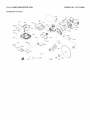
10 in. COMPOUND
MINTER SAW
MODEL
NO. 137.212290
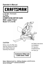
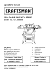
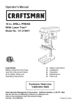
SCHEMATIC FOR SAW
0CV5
ODfB
C_/_
2CIA
0KQ_\
0_UK
OLS9
083S
OKB[
3CES
ssx%
2CSB
OKA9
2COF
OKTZ
.2D8M
OKTX.
0KSC
_'2CU6
_
2C8D
OJMM
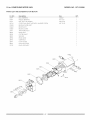
10 in. COMPOUND
B/liTER SAW
MODEL
NO. 137.212290
PARTS LIST AND SCHEB_IATtC FOR MOTOR
i.D. NO
DescfipJion
Size
0HVY
BALL BEARING
6204ZZ
0HX9
NEEDLE BEARING
HK-1010
1
0JX3
HEX. SOC.
M5_0.8-8
2
0KCN
CR.RE.
M5_12-50
2
0QQS
BRUSH HOLDER
0QQT
BRUSH ASS'Y
2
0QR0
BRUSH COVER
2
2AKT
ARMATURE
2BPA
FIELD ASS'Y
2BPB
CUTTER SHAFT
2BPC
SPACER
2BPD
HELIX GEAR
2BPE
GEAR
BOX
2BPF
FLOW
GUIDE
2BPP
MOTOR
2CVE
LEAD WiRE ASS'Y
SET SCREW
PAN HEAD TAPPING
& WASHER
SCREW
QTY
1
ASS'Y
2
ASS'Y
COVER
2BPA
OKCN_
oqqsi
0QR02
2BPF_
2CVE
0HX9
2BP£
2BPC
0HVY_
2BPB
Your
Home
For repair - in your home - of all major brand appfiances,
lawn and garden equipment, or heating and coofing systems,
no matter who made it, no matter who soJd it!
For the replacement
parts, accessories
and
Operator's Manuals that you need to do-it-yourself.
For Sears professional installation of home appfiances
and items like garage door openers and water heaters.
1-800-4-MY-HOME
Call anytime,
®
(1-800-469-4663)
day or night (U.S.A. and Canada)
www.sears.com
Our
sears.ca
Home
For repair of carry-in items fike vacuums,
and electronics,
lawn equipment,
carl or go ondine for the location of your nearest
Sears Parts & Repair Center.
1-800-488-1222
Call anytime,
day or night (U.S.A. only)
wwwosearsooom
To purchase a protection
1-800-827-6655
Para pedir servicio
a domicflio,
agreement
on a product serviced by Sears:
(U.S.A.)
de reparaci6n
y para ordenar
1-888oSU-HOGAR
1-800-361-6665
Au Canada pour service
loS00-LE-FOYER
piezas:
sM
® Marca
Trademark
Registrada
MC Marque
/ TM Trademark
/ TM Marca
de commerce
/ SM Service
de FAbrica / SM Mama
/ MD Marque
d6pos_e
en frangais:
M°
(1-800-533-6937)
(1 o888-784-6427)
® Registered
(Canada)
sears.ca
Mark of Sears,
de Servicio
de Sears,
Roebuck
Roebuck
de Sears,
and Co.
and Co.
Roebuck
and Co.
© Sears, Roebuck and Co.
2005.07. REV t