1
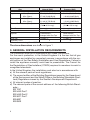
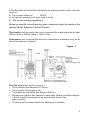
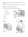
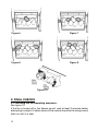
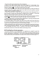
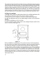
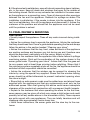
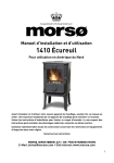
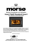
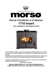
Squirrel - Gas Stoves
Model No. 551 - With Open Flue
INSTALLATION INSTRUCTIONS
This appliance is for use with natural gas (G20)
When converted using conversion kit no. 555111 this appliance is for use with propane gas (G31)
This appliance is suitabel only for use in the United
Kingdom (GB) and the Republic of Ireland (IE) only.
We trust that these instructions give sufficient details to enable this appliance to be installed and maintained satisfactorily. However, if further
information is required, our Technical Helpline will be pleased to help.
Telephone 01788554410 (National call rates apply in the United Kingdom).
Installer: Please leave this guide with the owner
Manufactured by Morsø Jernstøberi A/S . DK-7900 Nykøbing Mors
E-Mail: [email protected] · Website: www.morsoe.com
Distributed by Morsø UK, Unit 5, io Center, Valley Drive, Swift Walley,
Rugby, Warks, CV21 1TW - www.morsouk.com
LIST OF CONTENTS
Section
Heading
Page
1. SAFETY 3
2. APPLIANCE DATA 3
3.GENERAL INSTALLATION REQUIREMENTS 4
4. STOVE LOCATION 6
5. GAS SUPPLY CONNECTION 6
6. PACK CONTENTS 7
7. IGNITION CHECK 7
8. FITTING THE CERAMIC FUEL EFFECT
AND BURNER COMPARTMENT WALLS 8
9. FINAL CHECKS 10
9.1 Checking the full operating sequence. 10
9.2 Checking the reference pressure. 11
9.3 Check for spillage 12
10. FINAL REVIEW & SERVICING 13
1. SAFETY
Installer
Before continuing any further with the installation of this appliance please
read the following guide to manual handling.
• The lifting weight of this appliance is 53.5 kg.
• This stove is heavy. We therefore recommend that two people should be sufficient to lift the stove. If fitting or moving the appliance alone we recommend the use of suitable lifting apparatus.
• When lifting always keep your back straight. Bend your legs and not your back.
• Avoid twisting at the waist. It is better to reposition your feet.
• Avoid upper body/top heavy bending. Do not lean forward or sideways whilst handling the stove.
• Always grip with the palm of the hand. Do not use the tips of fingers for support.
• Always keep the stove as close to the body as possible. This will minimise the cantilever action.
• Use gloves to provide additional grip.
• Always use assistance if required.
2. APPLIANCE DATA
This product uses fuel effect pieces, burner compartment walls and gaskets
containing Refractory Ceramic Fibres (RCF), which are man-made vitreous
silicate fibres. Excessive exposure to these materials may cause temporary
irritation to eyes, skin and respiratory tract. Consequently, it makes sense to
take care when handling these articles to ensure that the release of dust is
kept to a minimum. To ensure that the release of fibres from these RCF articles
is kept to a minimum, during installation and servicing we recommend that
you use a HEPA filtered vacuum to remove any dust and soot accumulated in
and around the stove before and after working on the stove. When replacing
these articles we recommend that the replaced items are not broken up, but
are sealed within a heavy duty polythene bag, clearly labelled as RCF waste.
This is not classified as “hazardous waste” and may be disposed of at a
tipping site licensed for the disposal of industrial waste. Protective clothing
is not required when handling these articles, but we recommend you follow
the normal hygiene rules of not smoking, eating or drinking in the work area
and always wash your hands before eating or drinking.
This appliance does not contain any component manufactured from asbestos or asbestos related products.
Gas
Natural (G20)
Inlet Pressure
20mbar
Input Max. (Gross)
5.7 kW (19,450 Btu/h)
Min. (Gross)
1.7 kW (5,800 Btu/h)
Output
Max. (Gross)
3.8 kW (12,970 Btu/h)
Min. (Gross)
1.1 kW (3,755 Btu/h)
Burner Test Pressure (Cold)
19.6 +0.75mbar (7.86 ± 0.3 in w.g.)
Gas Connection
8 mm pipe
Burner Injector
Cat. 82 Size 360
Ignition
Piezo Electric.
Intergral with Gas Tap
Gas rate 0.539m3/h
Efficiency class
2
* When converted using Kit no. 555211.
Propane (G31)*
37mbar
5.1 kW (17,400 Btu/h)
1.9 kW (6,485 Btu/h)
3.6 kW (12,285 Btu/h)
1.2 kW (4,095 Btu/h)
35.9+0.75 mbar
(14.41 ± 0.3 in w.g.)
8 mm pipe
Cat. 92 size 160
Piezo Electric.
Intergral with Gas Tap
0.190m3/h
2
The stove dimensions are shown in figure 1
3. GENERAL INSTALLATION REQUIREMENTS
The installation must be in accordance with these instructions.
For the user’s protection, in the United Kingdom it is the law that all gas
appliances are installed by competent persons in accordance with the current edition of the Gas Safety (Installation and Use) Regulations. Failure to
install the appliance correctly could lead to prosecution. The Council for
the Registration of Gas Installers (CORGI) requires its members to work to
recognised standards.
In the United Kingdom the installation must also be in accordance with:
a) All the relevant parts of local regulations.
b) The current edition of the Building Regulations issued by the Department
of the Environment and the Welsh Office or the Building Standards (Scotland) Regulations issued by the Scottish Development Department.
c) All relevant codes of practice.
d) The relevant parts of the current editions of the following British Standards:BS 1251
BS 5440 Part 1
BS 5440 Part 2
BS 5871 Part 1
BS 6891
BS 8303
In the Republic of Ireland the installation must also conform to the relevant
parts of:
a) The current edition of
IS 813
b) All relevant national and local rules in force.
c) The current building regulations.
Where no specific instructions are given, reference should be made to the
relevant British Standard Code of Practice.
The hearth must be made from a non-combustible material and be at least
400mm wide x 420mm deep x 12mm thick.
Clearances from combustible and non-combustible materials must be at
least those shown in figure 1.
Figure 1
The flue details are shown in figure 1.
• The minimum flue diameter is 120mm.
• The minimum flue height is 3m.
• The maximum horizontal flue length is 300mm.
• No restrictor plate or flue damper is permitted. Where a variable damper is fitted it must be removed or be permanently fixed in the open position.
• The flue must be swept before the appliance is installed.
Ventilation: Normal adventitious ventilation is usually sufficient to satisfy the
ventilation requirements of this appliance. In GB reference should be made
to BS 5871 Part 2 and in IE reference should be made to the current edition
of IS 813 “Domestic gas Installations” which makes clear the conditions that
must be met to demonstrate that sufficient ventilation is available.
Location: This appliance must not be installed in a private garage or any room,
which contains a bath, or shower or where steam is regularly present.
Propane gas appliances must not be installed in a cellar, basement or other
room which is built entirely below ground level (See Gas Safety (Installation
& Use) Regulations).
A fireguard complying with BS 8423 should be fitted for the protection of
young children, the elderly, or the infirm. Such a guard is also recommended
for the protection of pets.
Atmosphere sensing device. The appliance is fitted with an A.S.D (Atmosphere sensing device). If the appliance closes down after a period of operation
for no apparent reason, the consumer should be informed to stop using the
appliance until the installation and appliance have been thoroughly checked.
The A.S.D will shut the appliance down if an unacceptable amount of harmful products of combustion accumulate. Under no circumstances should
the A.S.D be altered or bypassed in any way. Only a genuine manufacturers
replacement part should be fitted. The individual A.S.D components are not
replaceable.
4. STOVE LOCATION
1. Decide on whether the stove is to be used in rear or top outlet set-up and remove the appropriate outlet cover plate. The cover plate must be securely
attached to the unused flue outlet.
2. Place the stove in position on the hearth ensuring that the minimum di-
mensions specified in figure 1 are adhered to. Connect the flue pipe to the outlet and seal in place.
3. Due to its weight there is normally no requirement for additional fixing with this appliance.
5. GAS SUPPLY CONNECTING
• A nut and olive are provided for an 8mm pipe inlet connection to the elbow at the bottom front of the appliance. The elbow can be rotated to allow a connection from any direction. The elbow includes a valve for isolating the gas supply.
• The supply pipe must be rigid material. Flexible pipe must not be used.
• Note: Prior to connecting the gas supply it is advisable to blow out
the gas supply so that any dirt which may be present in the pipe is cleared and cannot enter the gas valve or pilot burner and so cause a blockage.
• With the supply connected pressure check the installation pipework for gas soundness. In the United Kingdom check in accordance with the
current edition of BS6891. In the Republic of Ireland check in accordance
with the rules in force.
6. PACK CONTENTS
1 Cast iron stove containing gas burner unit & interior flueway
1 8mm nut & olive
1 Key for door
1 Rope seal
2 Ceramic base pieces
1 Set of 7 coals
1 Pair of ceramic firebox side walls
2 Side wall retaining brackets
1 Ceramic firebox back wall
Remove all the items carefully to prevent damage. Take special care when
handling the ceramic components. Some items may be contained in the
packaging fitments - Examine the packaging carefully before discarding.
Check that all the items are present and undamaged.
7. IGNITION CHECK
Before attempting to install, it is worth checking that the ignition system
performs satisfactorily.
Set the right hand control knob to the off position marked •.
Depress the right hand control knob and rotate it anticlockwise through the
ignition position marked
to the pilot ignition position marked
. A ‘click’
will be heard as the integral piezo operates. A spark should be seen between
the electrode and pilot tip. If there is no spark check the following: • Ensure that the electrode lead is connected to the terminal at the base
of the electrode.
• If the above is correct, check for damage to the electrode lead.
8. FITTING THE CERAMIC FUEL EFFECT & BURNER COMPARTMENT WALLS
1. The door is secured with a locking screw. Remove the screw with the
allen key supplied (See figure 2). Open the door.
2. Remove the front grate. To do this, hold firmly and lift.
3. Place the rear ceramic wall against the back of the firebox.
4. The rear ceramic wall must be located onto the ledges at the back of
the rear base ceramic (See figure 3). To achieve this, hold the rear ceramic
wall against the rear of the firebox at its uppermost position. Whilst holding
the rear ceramic wall in this position locate the rear ceramic base coal into
position (See figure 3). The rear wall can now be released. Ensure that the
rear ceramic wall sits on the ledge at the back of the rear base coal.
5. Fit the left hand side wall against the left hand side of the firebox. Locate
the bottom of the side wall into the channel along the bottom of the firebox
(See figure 4). Supplied with the stove are two ceramic retaining brackets.
One for each side of the firebox. Hold the ceramic side wall against the steel
firebox plate and slide the long leg of a retaining bracket behind the steel
firebox plate. Push down to hold the ceramic side wall in place.
6. Fit the right hand side wall against the right hand side of the firebox.
Locate the bottom of the side wall into the channel along the bottom of the
firebox. Hold the ceramic side wall against the steel firebox plate and slide
the long leg of a retaining bracket behind the steel firebox plate. Push down
to hold the ceramic side wall in place.
7. On the front of the burner there is a bracket for supporting the front ceramic base. At the rear of the front ceramic base is a recess. Fit the front
ceramic base piece locating the recess onto the forward projecting part of
the burner bracket (See figure 5).
There are seven overlay coals. There are three ceramic coals identified with
the number’1’. Two identified with the number ‘2’ and two identified with
the number ‘3’.
8. Locate one of the ceramic coals identified with a number ‘1’ as in figur
6.
9. Locate the two ceramic coals identified with a number ‘2’ as in figure 7.
10. Locate the remaining two ceramic coals identified with a number ‘1’ as
in figure 8.
11. Locate the two ceramic coals identified with a number ‘3’ as in figure
9.
12. Replace the front grate previously removed .
13. Close and secure the door by refitting the locking screw.
Figure 3
Figure 2
Figure 4
Figure 5
Figure 6
Figure 7
Figure 8Figure 9
9. FINAL CHECKS
Figure 10
9.1 Checking the full operating sequence.
See figure 10.
If the fire is turned off or the flames go out, wait at least 3 minutes before
attempting to relight. A safety device in the control stops the fire being turned
back on until it is safe.
10
• Turn the left hand control knob fully clockwise.
• Push in the right control knob and, while keeping it depressed, turn
anticlockwise through the ignition position marked
and up to the pilot
position marked
. The spark should light the pilot.
• If the pilot does not ignite, keep the knob depressed for a few seconds to
purge air from the supply pipes. Then turn back to the off position marked
• and repeat the ignition procedure.
• When the pilot has lit, keep the right hand control knob depressed for a
few seconds to allow the pilot flame to stabilise then release it. If the pilot
does not remain alight ensure that the air has been purged.
• Partially depress the right control knob and turn to the main burner position
marked
. The main burner should now light at its low position.
• The left-hand knob is for burner flame adjustment. Turning it anticlockwise
should gradually increase the flame height.
• The flame height control does not have to be re-set every time the fire is
lit. It can be kept at any position enabling the customer to use the right hand
control only to ignite the burner at the set flame height.
• After checking turn the right hand knob to off. Depress the control knob partially at the pilot position marked
, turn clockwise to off position marked
• ! and release the knob. If any resistance is felt when turning, release the
downward pressure on the knob before continuing to turn.
9.2 Checking the reference pressure.
The burner aeration is non-adjustable. The appliance is preset to give the
correct heat input on Natural Gas at 20 mbar (8in w.g) inlet pressure and no
further adjustment is necessary. The burner pressure should be checked at
the pressure test point located at the side of the control unit (See figure 11).
Figure 11
11
The pressure check should be carried out using a calibrated pressure gauge
after removing the test point screw. The fire should be alight and the left hand
control knob at its fully anticlockwise setting (Maximum flame height). The
pressure setting should be within the limits shown on page 3 of this manual
(Appliance data). After checking the pressure, turn the fire off, remove the
pressure gauge and replace the pressure test sealing screw. Relight the fire
and test all gas joints for soundness using a suitable leak detection fluid.
9.3 Check for spillage
A spillage check must be made before leaving the installed appliance with
the customer. Make this with all the ceramic coals in position.
1. Close all doors and windows in the room containing the appliance.
2. Light the appliance and turn the flame-height control to the maximum
position.
3. Leave the appliance on for 5 minutes.
4. Hold a lighted smoke match close to the draught diverter outlet at the
back of the stove (See figure 12).
Figure 12
5. The installation is satisfactory if the smoke is drawn into the appliance.
6. If the smoke is not drawn into the appliance, leave the appliance alight at
the maximum setting for a further ten minutes and then repeat the test.
7. If the smoke is still not drawn into the appliance, turn off the appliance
and allow to cool. Check the flue installation and clearance of the draught
diverter from the rear surface. If no solution can be found, turn off the appliance and disconnect it. Advise the customer of the problem and stress
that the appliance must not be used until the problem is solved. If necessary
seek expert advice.
12
8. If the above test is satisfactory, open all internal connecting doors, hatches,
etc. in the room. Keep all doors and windows that open to the outside of
the building closed. Switch on any extractor fan installed in the same room
as the appliance or a connecting room. Open all doors and other openings
between the fan and the appliance. Recheck for spillage as above The
installation is satisfactory if the smoke is drawn into the appliance. If the
test is not satisfactory, turn off the appliance and disconnect it. Advise the
customer of the problem and stress that the appliance must not be used
until the problem is solved.
10. FINAL REVIEW & SERVICING
Final Review
• Visually inspect the appliance. Clean off any marks incurred during installation.
• Advise the customer how to operate the appliance. Advise the customer
that they should read their Owner’s guide before operating the fire and always
follow the advice in the section headed “Cleaning your stove”.
• Advise the customer that the top, front, sides and back of the appliance
are working surfaces and become very hot during use and, therefore care
should be exercised, particularly with the young, elderly or infirm.
• Explain to the customer that the appliance has a flame failure & spillage
monitoring system. Point out the explanation of this system shown in the
owner guide under “Operating your stove”. Advise that if the fire goes out
for any reason wait at least three minutes before relighting. Stress that if
the monitoring system repeatedly shuts off the fire, the appliance should be
switched off and a specialist should be consulted.
• Advise the customer that the window can be opened for cleaning the
interior by using the special key supplied. Stress that the window locking
screw should be refitted afterwards to prevent inadvertent opening when
the stove is alight.
• Stress that no extra ceramic coals must be added over and above those
supplied with the appliance and that any replacements must only be the
authorised spares. Warn that ignoring this advice could cause incomplete
clearance of the products of combustion with consequent health hazards.
• Explain to the customer that when operating the stove for the first time,
some vapours may be given off which may cause a slight odour and could
possibly set off any smoke alarms in the immediate vicinity. These vapours
are quite normal with new appliances. They are totally harmless and will
disappear after approximately twelve hours use.
• Hand these instructions, the owner guide and the door key to the customer.
13
• Recommend that the appliance should be serviced and the flue checked
by a competent person (In the UK preferably a CORGI registered person) at
least annually. If the appliance is in premises in the United Kingdom occupied
by a tenant, point out that by law a landlord must have any gas appliance,
flue and pipework which is situated in a tenant’s premises checked for safety
at least every 12 months.
Servicing
• Always turn off the gas supply and allow to cool completely before commencing any servicing.
• This product uses fuel effect pieces and burner compartment walls
containing Refractory Ceramic Fibres (RCF), which are man-made vitreous silicate fibres. Excessive exposure to these materials may cause
irritation to eyes, skin and respiratory tract. Consequently, it is important
to take care when handling these articles to ensure that the release
of dust is kept to a minimum. To ensure that the release of fibres from
these RCF articles is kept to a minimum, during installation and servicing we recommend that you use a HEPA filtered vacuum to remove
any dust and soot accumulated in and around the fire before and after
working on the fire. When replacing these articles we recommend that
the replaced items are not broken up, but are sealed within a heavy duty
polythene bag, clearly labelled as RCF waste. This is not classified as
“hazardous waste” and may be disposed of at a tipping site licensed
for the disposal of industrial waste. Protective clothing is not required
when handling these articles, but we recommend you follow the normal
hygiene rules of not smoking, eating or drinking in the work area and
always wash your hands before eating or drinking.
This appliance does not contain any component manufactured from
asbestos or asbestos related products.
• Check that the appliance is clean and that no matter is blocking the burner
or pilot which may cause imperfect flames or prevent a correct electrode
spark.
• After servicing, make sure that the ceramic walls and fuel effect pieces
are replaced correctly as described in this guide. Make sure that the door
locking screw is in place.
• Always test for gas soundness after servicing the appliance.
14
15
Morsø Jernstøberi A/S - 18.12.2006 - 72146100
16