1
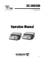
DC-200/300
Counting Scale
21.51
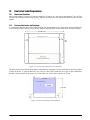
CountingVersion
Scale
Operation Manual
77157
Contents
About This Manual ................................................................................................................................... 1
1.0
Introduction.................................................................................................................................. 1
1.1 Capacities and Resolutions . . . . . . . . . . . . . . . . . . . . . . . . . . . . . . . . . . . . . . . . . . . . . . . . . . . . . . . . 1
1.2 Modes of Operation. . . . . . . . . . . . . . . . . . . . . . . . . . . . . . . . . . . . . . . . . . . . . . . . . . . . . . . . . . . . . . 3
1.2.1
Description of Modes of Operation . . . . . . . . . . . . . . . . . . . . . . . . . . . . . . . . . . . . . . . . . . . . . . . . . . . . 3
1.3 Keyboard and Display . . . . . . . . . . . . . . . . . . . . . . . . . . . . . . . . . . . . . . . . . . . . . . . . . . . . . . . . . . . . 5
1.3.1
1.3.2
2.0
Installation ................................................................................................................................... 8
2.1
2.2
2.3
2.4
2.5
2.6
3.0
Annunciators. . . . . . . . . . . . . . . . . . . . . . . . . . . . . . . . . . . . . . . . . . . . . . . . . . . . . . . . . . . . . . . . . . . . . 5
Key Functions . . . . . . . . . . . . . . . . . . . . . . . . . . . . . . . . . . . . . . . . . . . . . . . . . . . . . . . . . . . . . . . . . . . . 5
Unpacking . . . . . . . . . . . . . . . . . . . . . . . . . . . . . . . . . . . . . . . . . . . . . . . . . . . . . . . . . . . . . . . . . . . . . 8
Repacking . . . . . . . . . . . . . . . . . . . . . . . . . . . . . . . . . . . . . . . . . . . . . . . . . . . . . . . . . . . . . . . . . . . . . 9
Setting Up . . . . . . . . . . . . . . . . . . . . . . . . . . . . . . . . . . . . . . . . . . . . . . . . . . . . . . . . . . . . . . . . . . . . . 9
Powering Up the DC-200/300 . . . . . . . . . . . . . . . . . . . . . . . . . . . . . . . . . . . . . . . . . . . . . . . . . . . . . . 9
Setting Time and Date . . . . . . . . . . . . . . . . . . . . . . . . . . . . . . . . . . . . . . . . . . . . . . . . . . . . . . . . . . . 10
Battery Installation (DC-200 only) . . . . . . . . . . . . . . . . . . . . . . . . . . . . . . . . . . . . . . . . . . . . . . . . . . . 11
Configuration Settings ............................................................................................................... 13
3.1 Configuring Specification 141 and 142 Settings from the Scale Keyboard . . . . . . . . . . . . . . . . . . . . 13
3.1.1
3.1.2
Customer Specification (141 Settings). . . . . . . . . . . . . . . . . . . . . . . . . . . . . . . . . . . . . . . . . . . . . . . . . 13
Weight and Measurement Specification (142 Settings) . . . . . . . . . . . . . . . . . . . . . . . . . . . . . . . . . . . . 20
3.2 Configuring Spec 141 and 142 Settings Using the Spec Upload Utility . . . . . . . . . . . . . . . . . . . . . . 25
3.2.1
3.2.2
4.0
5.0
Change Spec Settings Using the Spec Upload Utility . . . . . . . . . . . . . . . . . . . . . . . . . . . . . . . . . . . . . 25
Uploading Saved Spec Configurations to a DC-200/300. . . . . . . . . . . . . . . . . . . . . . . . . . . . . . . . . . . 29
Calibration ................................................................................................................................. 33
Scale Operations........................................................................................................................ 36
5.1 Weight Unit Switching . . . . . . . . . . . . . . . . . . . . . . . . . . . . . . . . . . . . . . . . . . . . . . . . . . . . . . . . . . . 37
5.2 Toggle Between Scales . . . . . . . . . . . . . . . . . . . . . . . . . . . . . . . . . . . . . . . . . . . . . . . . . . . . . . . . . . 37
5.3 Setting Tare Weights in Operation Mode . . . . . . . . . . . . . . . . . . . . . . . . . . . . . . . . . . . . . . . . . . . . . 37
5.3.1
5.3.2
5.3.3
5.3.4
One Touch Tare (When the Tare Weight is Unknown) . . . . . . . . . . . . . . . . . . . . . . . . . . . . . . . . . . . . .
Digital Tare (When Tare Weight is Known in Advance). . . . . . . . . . . . . . . . . . . . . . . . . . . . . . . . . . . . .
Tare Addition or Subtraction . . . . . . . . . . . . . . . . . . . . . . . . . . . . . . . . . . . . . . . . . . . . . . . . . . . . . . . .
Tare Exchange or Override . . . . . . . . . . . . . . . . . . . . . . . . . . . . . . . . . . . . . . . . . . . . . . . . . . . . . . . . .
37
37
38
38
5.4 Toggling Between Gross and Net . . . . . . . . . . . . . . . . . . . . . . . . . . . . . . . . . . . . . . . . . . . . . . . . . . 38
5.5 Entering Unit Weights . . . . . . . . . . . . . . . . . . . . . . . . . . . . . . . . . . . . . . . . . . . . . . . . . . . . . . . . . . . 39
5.5.1
5.5.2
Unit Weight Operation by Sampling. . . . . . . . . . . . . . . . . . . . . . . . . . . . . . . . . . . . . . . . . . . . . . . . . . . 40
Unit Weight Operation by Key Entry . . . . . . . . . . . . . . . . . . . . . . . . . . . . . . . . . . . . . . . . . . . . . . . . . . 40
5.6 Setting the Default Label Format (DC-300 only) . . . . . . . . . . . . . . . . . . . . . . . . . . . . . . . . . . . . . . . .
5.7 Setting a Lot Number . . . . . . . . . . . . . . . . . . . . . . . . . . . . . . . . . . . . . . . . . . . . . . . . . . . . . . . . . . .
5.8 Setting a Sequence Number (DC-300 only) . . . . . . . . . . . . . . . . . . . . . . . . . . . . . . . . . . . . . . . . . . .
5.9 Changing the Factory Name (DC-300 only) . . . . . . . . . . . . . . . . . . . . . . . . . . . . . . . . . . . . . . . . . . .
5.10 Operations Without Recalling an ID Code. . . . . . . . . . . . . . . . . . . . . . . . . . . . . . . . . . . . . . . . . . . .
5.10.1
5.10.2
40
41
41
42
42
Using Item Codes and Part Names Without Storing Them to Memory . . . . . . . . . . . . . . . . . . . . . . . . 42
Part Accumulation and Negative Counting - Without Recalling an Item Code . . . . . . . . . . . . . . . . . . . 43
Technical training seminars are available through Rice Lake Weighing
Systems. Course descriptions and dates can be viewed at www.rlws.com or
obtained by calling 715-234-9171 and asking for the training department.
© 2005 Rice Lake Weighing Systems. All rights reserved. Printed in the United States of America.
Specifications subject to change without notice.
Version 21.51, May 2005
5.10.3
5.10.4
Sample, Count and Print a Label . . . . . . . . . . . . . . . . . . . . . . . . . . . . . . . . . . . . . . . . . . . . . . . . . . . . 44
Scan ID Bar Code, Count, and Print a Label . . . . . . . . . . . . . . . . . . . . . . . . . . . . . . . . . . . . . . . . . . . . 44
5.11 Using Item Codes in Normal or Operation Mode . . . . . . . . . . . . . . . . . . . . . . . . . . . . . . . . . . . . . . 45
5.11.1
5.11.2
5.11.3
5.11.4
5.11.5
5.11.6
6.0
Recalling Item Codes using Item Code Number . . . . . . . . . . . . . . . . . . . . . . . . . . . . . . . . . . . . . . . . .
View Item Information . . . . . . . . . . . . . . . . . . . . . . . . . . . . . . . . . . . . . . . . . . . . . . . . . . . . . . . . . . . . .
Re-Computing Item Code Unit Weight . . . . . . . . . . . . . . . . . . . . . . . . . . . . . . . . . . . . . . . . . . . . . . . .
Quick Add Item to Memory . . . . . . . . . . . . . . . . . . . . . . . . . . . . . . . . . . . . . . . . . . . . . . . . . . . . . . . . .
Adding Parts To and Subtracting Parts From Inventory . . . . . . . . . . . . . . . . . . . . . . . . . . . . . . . . . . .
Delete Item Memory . . . . . . . . . . . . . . . . . . . . . . . . . . . . . . . . . . . . . . . . . . . . . . . . . . . . . . . . . . . . . .
45
45
46
46
47
48
Scale Programming ................................................................................................................... 49
6.1 Item Code Storage . . . . . . . . . . . . . . . . . . . . . . . . . . . . . . . . . . . . . . . . . . . . . . . . . . . . . . . . . . . . . 49
6.1.1
6.1.2
6.1.3
6.1.4
Checking Memory Status . . . . . . . . . . . . . . . . . . . . . . . . . . . . . . . . . . . . . . . . . . . . . . . . . . . . . . . . . . 50
Program ID Code, Unit Weight, Tare Weight, Label Format, Part Name, Part Number, Lot Number, Location, Inventory Quantity, Threshold, Setpoints, Address Number 50
View Item Codes in Memory . . . . . . . . . . . . . . . . . . . . . . . . . . . . . . . . . . . . . . . . . . . . . . . . . . . . . . . . 52
Delete Item Memory . . . . . . . . . . . . . . . . . . . . . . . . . . . . . . . . . . . . . . . . . . . . . . . . . . . . . . . . . . . . . . 52
6.2 Uploading and Downloading Items Between the Scale and a Computer . . . . . . . . . . . . . . . . . . . . . 52
6.2.1
6.2.2
6.2.3
6.2.4
7.0
Item Database File Format . . . . . . . . . . . . . . . . . . . . . . . . . . . . . . . . . . . . . . . . . . . . . . . . . . . . . . . . .
Installing the DC-300 Utility Program. . . . . . . . . . . . . . . . . . . . . . . . . . . . . . . . . . . . . . . . . . . . . . . . . .
Item Uploading From the Scale . . . . . . . . . . . . . . . . . . . . . . . . . . . . . . . . . . . . . . . . . . . . . . . . . . . . . .
Item Downloading To the Scale . . . . . . . . . . . . . . . . . . . . . . . . . . . . . . . . . . . . . . . . . . . . . . . . . . . . .
53
54
58
60
Printing Labels (DC-300 only).................................................................................................... 64
7.1 Thermal Label Printer. . . . . . . . . . . . . . . . . . . . . . . . . . . . . . . . . . . . . . . . . . . . . . . . . . . . . . . . . . . . 64
7.1.1
7.1.2
7.1.3
7.1.4
7.1.5
7.1.6
7.1.7
7.1.8
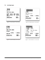
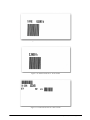
Available Label Types . . . . . . . . . . . . . . . . . . . . . . . . . . . . . . . . . . . . . . . . . . . . . . . . . . . . . . . . . . . . .
Label Format Samples . . . . . . . . . . . . . . . . . . . . . . . . . . . . . . . . . . . . . . . . . . . . . . . . . . . . . . . . . . . .
Character Sizes Available for Printing . . . . . . . . . . . . . . . . . . . . . . . . . . . . . . . . . . . . . . . . . . . . . . . . .
Label and Paper Roll Set-Up. . . . . . . . . . . . . . . . . . . . . . . . . . . . . . . . . . . . . . . . . . . . . . . . . . . . . . . .
Cleaning the Thermal Printer Head . . . . . . . . . . . . . . . . . . . . . . . . . . . . . . . . . . . . . . . . . . . . . . . . . . .
Checking or Rezeroing the Thermal Head Usage Counter. . . . . . . . . . . . . . . . . . . . . . . . . . . . . . . . . .
Adjusting Printing Position. . . . . . . . . . . . . . . . . . . . . . . . . . . . . . . . . . . . . . . . . . . . . . . . . . . . . . . . . .
Turning On and Off the Internal Printer . . . . . . . . . . . . . . . . . . . . . . . . . . . . . . . . . . . . . . . . . . . . . . . .
64
65
70
71
72
72
73
73
7.2 Programming Fields for Label Printing . . . . . . . . . . . . . . . . . . . . . . . . . . . . . . . . . . . . . . . . . . . . . . . 74
7.2.1
7.2.2
7.2.3
7.2.4
Programming Factory Name Files . . . . . . . . . . . . . . . . . . . . . . . . . . . . . . . . . . . . . . . . . . . . . . . . . . . .
Programming Address Files . . . . . . . . . . . . . . . . . . . . . . . . . . . . . . . . . . . . . . . . . . . . . . . . . . . . . . . .
Programming Text Files . . . . . . . . . . . . . . . . . . . . . . . . . . . . . . . . . . . . . . . . . . . . . . . . . . . . . . . . . . .
Programming Logo Files . . . . . . . . . . . . . . . . . . . . . . . . . . . . . . . . . . . . . . . . . . . . . . . . . . . . . . . . . . .
74
75
77
79
7.3 DC-300 Label Format Editor . . . . . . . . . . . . . . . . . . . . . . . . . . . . . . . . . . . . . . . . . . . . . . . . . . . . . . 82
7.3.1
7.3.2
7.3.3
Installing the DC-300 Label Format Editor Software . . . . . . . . . . . . . . . . . . . . . . . . . . . . . . . . . . . . . . 82
Formatting a Label With the DC-300 Label Format Editor Software. . . . . . . . . . . . . . . . . . . . . . . . . . . 84
Saving and Uploading a Label Format. . . . . . . . . . . . . . . . . . . . . . . . . . . . . . . . . . . . . . . . . . . . . . . . . 87
7.4 Manual Printing of Labels. . . . . . . . . . . . . . . . . . . . . . . . . . . . . . . . . . . . . . . . . . . . . . . . . . . . . . . . . 90
7.4.1
7.4.2
Issuing an Item Label or Receipt . . . . . . . . . . . . . . . . . . . . . . . . . . . . . . . . . . . . . . . . . . . . . . . . . . . . . 90
Issuing a Total Label or Receipt . . . . . . . . . . . . . . . . . . . . . . . . . . . . . . . . . . . . . . . . . . . . . . . . . . . . . 90
7.5 Free Format Label Programming . . . . . . . . . . . . . . . . . . . . . . . . . . . . . . . . . . . . . . . . . . . . . . . . . . . 91
7.5.1
7.5.2
7.5.3
7.5.4
7.5.5
7.5.6
7.5.7
7.5.8
General Label Parameters. . . . . . . . . . . . . . . . . . . . . . . . . . . . . . . . . . . . . . . . . . . . . . . . . . . . . . . . . . 91
Print Area, Print Position and Print Angles . . . . . . . . . . . . . . . . . . . . . . . . . . . . . . . . . . . . . . . . . . . . . . 91
Kinds of Data That Can Be Included on a Free Format Label . . . . . . . . . . . . . . . . . . . . . . . . . . . . . . . 92
Item and Total Labels . . . . . . . . . . . . . . . . . . . . . . . . . . . . . . . . . . . . . . . . . . . . . . . . . . . . . . . . . . . . . 92
Programming Data Layout for Free Format Labels . . . . . . . . . . . . . . . . . . . . . . . . . . . . . . . . . . . . . . . 95
Checking Your Free Format Programming Layout. . . . . . . . . . . . . . . . . . . . . . . . . . . . . . . . . . . . . . . . 96
Example of Free Format Programming by Modifying an Existing Format . . . . . . . . . . . . . . . . . . . . . . . 97
Delete a Free Format File . . . . . . . . . . . . . . . . . . . . . . . . . . . . . . . . . . . . . . . . . . . . . . . . . . . . . . . . . 100
7.6 Changing Label Formats . . . . . . . . . . . . . . . . . . . . . . . . . . . . . . . . . . . . . . . . . . . . . . . . . . . . . . . . 101
7.6.1
7.6.2
7.6.3
7.6.4
Change Label Format Associated With an Individual Item Code . . . . . . . . . . . . . . . . . . . . . . . . . . . .
Change the Default Label Type . . . . . . . . . . . . . . . . . . . . . . . . . . . . . . . . . . . . . . . . . . . . . . . . . . . . .
Change the NON-ID Label Type . . . . . . . . . . . . . . . . . . . . . . . . . . . . . . . . . . . . . . . . . . . . . . . . . . . .
Change All Label Types Temporarily . . . . . . . . . . . . . . . . . . . . . . . . . . . . . . . . . . . . . . . . . . . . . . . . .
101
102
102
102
7.7 Using External Printers. . . . . . . . . . . . . . . . . . . . . . . . . . . . . . . . . . . . . . . . . . . . . . . . . . . . . . . . . . 102
ii
DC-200/300 Operation Manual
8.0
Job Sequence Programming ................................................................................................... 103
8.1
8.2
8.3
8.4
9.0
General Instructions . . . . . . . . . . . . . . . . . . . . . . . . . . . . . . . . . . . . . . . . . . . . . . . . . . . . . . . . . . . .
Example of Job Sequence Programming . . . . . . . . . . . . . . . . . . . . . . . . . . . . . . . . . . . . . . . . . . . .
Modifying a Job Sequence Step. . . . . . . . . . . . . . . . . . . . . . . . . . . . . . . . . . . . . . . . . . . . . . . . . . .
Deleting a Job Sequence Step . . . . . . . . . . . . . . . . . . . . . . . . . . . . . . . . . . . . . . . . . . . . . . . . . . . .
103
103
104
104
Reports ..................................................................................................................................... 105
9.1 Available Reports . . . . . . . . . . . . . . . . . . . . . . . . . . . . . . . . . . . . . . . . . . . . . . . . . . . . . . . . . . . . . . 105
9.2 Item Reports . . . . . . . . . . . . . . . . . . . . . . . . . . . . . . . . . . . . . . . . . . . . . . . . . . . . . . . . . . . . . . . . . 106
9.2.1
9.2.2
One Item Report . . . . . . . . . . . . . . . . . . . . . . . . . . . . . . . . . . . . . . . . . . . . . . . . . . . . . . . . . . . . . . . . 106
All Item Print . . . . . . . . . . . . . . . . . . . . . . . . . . . . . . . . . . . . . . . . . . . . . . . . . . . . . . . . . . . . . . . . . . . 107
9.3 Inventory Reports . . . . . . . . . . . . . . . . . . . . . . . . . . . . . . . . . . . . . . . . . . . . . . . . . . . . . . . . . . . . . . 108
9.3.1
9.3.2
9.3.3
Threshold Report . . . . . . . . . . . . . . . . . . . . . . . . . . . . . . . . . . . . . . . . . . . . . . . . . . . . . . . . . . . . . . . 108
In/Out Count Report . . . . . . . . . . . . . . . . . . . . . . . . . . . . . . . . . . . . . . . . . . . . . . . . . . . . . . . . . . . . . 108
Clearing the In/Out Count Register . . . . . . . . . . . . . . . . . . . . . . . . . . . . . . . . . . . . . . . . . . . . . . . . . . 109
9.4 Shelf Location Label Print (DC-300 only). . . . . . . . . . . . . . . . . . . . . . . . . . . . . . . . . . . . . . . . . . . . . 110
9.5 Programming Reports (DC-300 only) . . . . . . . . . . . . . . . . . . . . . . . . . . . . . . . . . . . . . . . . . . . . . . . 111
9.5.1
9.5.2
9.5.3
9.5.4
9.5.5
9.5.6
10.0
Factory Name Report (DC-300 only) . . . . . . . . . . . . . . . . . . . . . . . . . . . . . . . . . . . . . . . . . . . . . . . . .
Address File Report (DC-300 only) . . . . . . . . . . . . . . . . . . . . . . . . . . . . . . . . . . . . . . . . . . . . . . . . . .
Text File Report (DC-300 only). . . . . . . . . . . . . . . . . . . . . . . . . . . . . . . . . . . . . . . . . . . . . . . . . . . . . .
Logo File Report (DC-300 only) . . . . . . . . . . . . . . . . . . . . . . . . . . . . . . . . . . . . . . . . . . . . . . . . . . . . .
Label Layout Test Report (DC-300 only) . . . . . . . . . . . . . . . . . . . . . . . . . . . . . . . . . . . . . . . . . . . . . .
Free Format Label Layout Data Report (DC-300 only) . . . . . . . . . . . . . . . . . . . . . . . . . . . . . . . . . . . .
111
112
113
114
114
114
Password Protecting the Programming Functions ................................................................. 115
10.1 How to Program a Password . . . . . . . . . . . . . . . . . . . . . . . . . . . . . . . . . . . . . . . . . . . . . . . . . . . . 115
10.2 How to Use a Password . . . . . . . . . . . . . . . . . . . . . . . . . . . . . . . . . . . . . . . . . . . . . . . . . . . . . . . . 115
10.3 How to Change or Delete a Password . . . . . . . . . . . . . . . . . . . . . . . . . . . . . . . . . . . . . . . . . . . . . 115
11.0
Network Connection ................................................................................................................ 117
11.1 Checking the Scale’s IP Address . . . . . . . . . . . . . . . . . . . . . . . . . . . . . . . . . . . . . . . . . . . . . . . . .
11.2 Machine Setup Utility . . . . . . . . . . . . . . . . . . . . . . . . . . . . . . . . . . . . . . . . . . . . . . . . . . . . . . . . . .
11.3 Changing the IP Address Directly on the Scale . . . . . . . . . . . . . . . . . . . . . . . . . . . . . . . . . . . . . . .
11.4 Ethernet Cable Connection Between the Scale and the Computer . . . . . . . . . . . . . . . . . . . . . . . .
11.5 Setting the Computer’s Network Communication . . . . . . . . . . . . . . . . . . . . . . . . . . . . . . . . . . . . .
11.6 Entering the Data Transfer Mode on the Scale . . . . . . . . . . . . . . . . . . . . . . . . . . . . . . . . . . . . . . .
11.7 Exiting The Data Transfer Mode on the Scale . . . . . . . . . . . . . . . . . . . . . . . . . . . . . . . . . . . . . . . .
12.0
117
117
118
118
118
120
121
Appendix .................................................................................................................................. 122
12.1 DC-200/300 Error Message List . . . . . . . . . . . . . . . . . . . . . . . . . . . . . . . . . . . . . . . . . . . . . . . . . . 122
12.2 Interface Ports . . . . . . . . . . . . . . . . . . . . . . . . . . . . . . . . . . . . . . . . . . . . . . . . . . . . . . . . . . . . . . . 124
12.2.1
12.2.2
12.2.3
12.2.4
12.2.5
12.2.6
Overview of Interface Ports . . . . . . . . . . . . . . . . . . . . . . . . . . . . . . . . . . . . . . . . . . . . . . . . . . . . . . . .
Spec Settings for Interface Ports . . . . . . . . . . . . . . . . . . . . . . . . . . . . . . . . . . . . . . . . . . . . . . . . . . . .
Connection from Scale to PC via the RS-232 Port . . . . . . . . . . . . . . . . . . . . . . . . . . . . . . . . . . . . . .
Connection from Scale to PC via Ethernet Port . . . . . . . . . . . . . . . . . . . . . . . . . . . . . . . . . . . . . . . . .
Connection from Scale to Printer. . . . . . . . . . . . . . . . . . . . . . . . . . . . . . . . . . . . . . . . . . . . . . . . . . . .
Connection From Scale to Remote Platform . . . . . . . . . . . . . . . . . . . . . . . . . . . . . . . . . . . . . . . . . . .
124
124
128
129
129
131
12.3 Connecting an IBM Keyboard . . . . . . . . . . . . . . . . . . . . . . . . . . . . . . . . . . . . . . . . . . . . . . . . . . . . 131
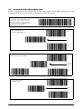
12.4 Connecting a Barcode Scanner . . . . . . . . . . . . . . . . . . . . . . . . . . . . . . . . . . . . . . . . . . . . . . . . . . 132
12.4.1
12.4.2
12.4.3
12.4.4
12.4.5
12.4.6
12.4.7
Header Codes. . . . . . . . . . . . . . . . . . . . . . . . . . . . . . . . . . . . . . . . . . . . . . . . . . . . . . . . . . . . . . . . . .
Z Commands via Barcodes . . . . . . . . . . . . . . . . . . . . . . . . . . . . . . . . . . . . . . . . . . . . . . . . . . . . . . . .
Configuring the RS232C Port for a Scanner . . . . . . . . . . . . . . . . . . . . . . . . . . . . . . . . . . . . . . . . . . .
Connecting the Scanner to the RS232C Port . . . . . . . . . . . . . . . . . . . . . . . . . . . . . . . . . . . . . . . . . .
Configuring the Keyboard Port for a Scanner . . . . . . . . . . . . . . . . . . . . . . . . . . . . . . . . . . . . . . . . . .
Programming the QSC-6000 Plus Quickscan RS232C Scanner . . . . . . . . . . . . . . . . . . . . . . . . . . . .
Programming the QuickScan Keyboard Wedge Scanner. . . . . . . . . . . . . . . . . . . . . . . . . . . . . . . . . .
133
134
134
134
134
135
140
12.5 Label Formatting Worksheets (DC-300 only) . . . . . . . . . . . . . . . . . . . . . . . . . . . . . . . . . . . . . . . . . 141
12.6 Character Code Tables . . . . . . . . . . . . . . . . . . . . . . . . . . . . . . . . . . . . . . . . . . . . . . . . . . . . . . . . . 160
12.6.1
ASCII Code . . . . . . . . . . . . . . . . . . . . . . . . . . . . . . . . . . . . . . . . . . . . . . . . . . . . . . . . . . . . . . . . . . . . 160
iii
12.6.2
Teraoka Codes . . . . . . . . . . . . . . . . . . . . . . . . . . . . . . . . . . . . . . . . . . . . . . . . . . . . . . . . . . . . . . . . . 162
13.0
DC-200/300 Limited Warranty ................................................................................................. 163
iv
DC-200/300 Operation Manual
About This Manual
This manual contains operating procedures for the DC-200/300 counting scales and provides the user with all the
information necessary for setup and operation. It is organized based on the procedures you will likely follow
when setting up and using your counting scale. This manual applies to Version 21.51 of the DC-200/300
counting scale series.
#AUTION
Some procedures described in this manual require work inside the scale base. These procedures are to
be performed by qualified service personnel only.
Authorized distributors and their employees can view or download this manual from the
DIGI distributor site at www.DigiScales.com.
1.0
Introduction
The DC-200/300 counting scale offers practical solutions for a full range of precision counting applications. A
bright dot matrix LCD display enables operators to easily view quantities, and a second line of alphanumeric text
messaging displays operator prompts and part numbers to enable job sequencing. Four thousand item memory,
three standard RS-232 interfaces and Ethernet connectivity enable the DC-200/300 Series to provide real-time
data collection and position it for the future growth of your business. Multiple scales can be connected to the
DC-200/300, as well as bar code scanners, external printers and keyboards, making it the hub of a sophisticated
weighing system. The DC-300’s built-in direct thermal printer instantaneously generates labels and allows you to
produce reports such as item, inventory and shelf location. Its ninety-nine custom label formats provide the
flexibility to create labels containing only the information needed for each application. When portability is
required, choose the battery operation option of the DC-200 for over 10 hours of continuous use for mobile
workstations, outdoor applications, and rental fleets. It’s built to withstand transport from one area of the plant to
another or from one business to the next. Simply connect a printer via RS-232 for labeling tasks.
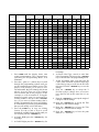
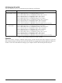
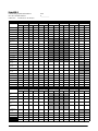
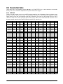
1.1
Capacities and Resolutions
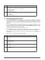
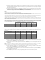
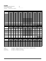
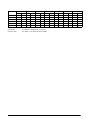
Table 1-1 and Table 1-2 list the scale capacities and resolutions for all models of the DC-200/300 counting
scales. The system weighing accuracy is 0.02 percent.
Counting scales specify two types of resolution:
• Weight (or external) resolution
• Counting (or internal) resolution
Weight resolution is displayed in divisions of the full scale capacity which is divided into weight increments. For
example, a 5-lb scale divided into 10,000 display divisions would display weight with 0.0005 lb divisions
(10,000 divisions x 0.0005 lb = 5.0 lb).
Counting resolution is based on the internal resolution of the scale. The weight and counting resolutions for the
DC-200/300 capacities are shown below and apply to all models of DC-200/300 counting scales.
Introduction
1
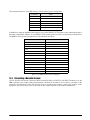
DC-200/300 Single Scale
Note: Units are selectable from lb to kg and can be programmed to weigh in other primary units: lb, kg, g.
Capacity
Mounting Internal/External
Weight Resolution
Counting Resolution
Platform Dimension
1.0 lb
Both
0.0001
0.000001
6" x 8"
2.5 lb
Both
0.0002
0.000002
7" x 10"
5.0 lb
Both
0.0005
0.000005
12" x 14"
10.0 lb
Both
0.001
0.00001
12" x 14"
25.0 lb
Both
0.002
0.00002
12" x 14"
50.0 lb
Both
0.005
0.00005
12" x 14"
Table 1-1. DC-200/300 Single Scale Capacities
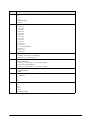
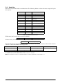
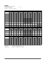
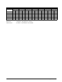
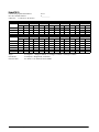
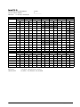
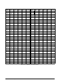
DC-200/300 Remote Platforms
Platform Capacity
Weight Resolution
Counting Resolution
Platform Dimensions
100.00
0.01
0.0001
13" x 17"
(DIGI S-SL Platform)
250.00
0.02
0.0002
17" x 21" *
(DIGI S-TL Platform)
500.00
0.05
0.0005
17" x 21" *
(DIGI S-TL Platform)
1500.0
0.2
0.001
24" x 28" *
(DIGI S-UL Platform)
2500.0
0.2
0.002
36" x 36” or 48" x 48" *
(DIGI Summit 3000 Platform)
5000.0
0.5
0.005
48" x 48" *
(DIGI Summit 3000 Platform)
10000.0
1.0
0.01
48" x 48" or 60" x 60" *
(DIGI Summit 3000 Platform)
25000.0
2.0
0.02
42" x 72" or 60" x 84" *
(DIGI Summit 3000 Platform)
50000.0
5.0
0.05
60" x 84" *
(DIGI Summit 3000 Platform)
*Note: Other platform sizes are available; consult the factory or your dealer for more information. Units are selectable from lb to
kg and can be programmed to weigh in other primary units: lb, kg, g.
Table 1-2. DC-200/300 External Platform Capacities
2
DC-200/300 Operation Manual
1.2
Modes of Operation
1.2.1
Description of Modes of Operation
The DC-200/300 has four main modes of operation:
• Operation Mode – where all the basic weighing and counting operations are performed (also called the
Registration Mode).
• Report Mode – where item, inventory, and shelf location reports can be printed.
• Program Mode –where item data, factory name, and other data can be programmed into the memory of
the scale.
• Password Mode – where you can set passwords that will be required for a scale operator to use certain
functions of the scale.
A fifth mode of operation, Service Mode, is used by your DIGI Dealer or authorized service technician to
perform initial programming and troubleshooting operations.
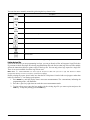
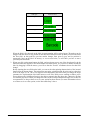
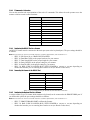
Which mode you are in is displayed on the right-hand side of the display panel by the following codes:
Mode
Operation Mode
Annunciator
Default mode, no letter displayed
Report Mode
X
Program Mode
S
Password Mode
The code for the mode you are password protecting is displayed
Service Mode
Z
Table 1-3. DC-200/300 Modes of Operation
Introduction
3
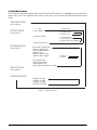
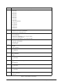
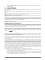
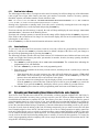
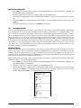
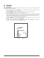
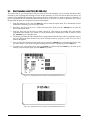
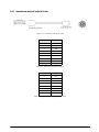
DC-200/300 Mode Flowchart
The chart below shows the functions under each of the DC-200/300 modes. Use the Mode key to switch between
modes. Once you are in a particular mode, use the + and – keys to move between the different functions for that
mode.
8&*()*/(.0%&
BOOVODJBUPS"
oLFZ
3&1035.0%&
BOOVOJDBUPS9
*UFN3FQPSU
*OWFOUPSZ3FQPS U
3FQSJOULFZ
0OF*UFN1SJOU
"MM*UFN1SJOU
5ISFTIPME1SJOU
*O0VU$PVOU3FQPSU
$MFBS*O0VU$PVOU3FQPSU
4IFMG-PDBUJPO1SJOU
130(3"..0%&
BOOVOJDBUPS4
*UFN$PEF1SPHSBNNJOH
'BDUPSZ1SPHSBNNJOH
1SPHSBN+PC4FRVFODF
1SPHSBN%BUF
"EESFTT1SPHSBNNJOH
(FOFSBM-BCFM1SPHSBN
5FYU1SPHSBNNJOH
1SPHSBN'SFF'PSNBU
-PHP1SPHSBNNJOH
*UFNT1SPHSBNNFE*UFNT"WBJMBCMF
4&37*$&.0%& BOOVOJDBUPS;
1"44803%.0%&
9.PEF1BTTXPSE
4.PEF1BTTXPSE
;.PEF1BTTXPSE
18%.%1BTTXPSE
Figure 1-1. Mode Flowchart
4
DC-200/300 Operation Manual
/PO*%
%FGBVMU
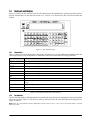
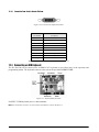
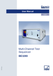
1.3
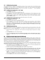
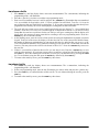
Keyboard and Display
Figure 1-2 shows the DC-200/300 console with annunciators, the alphanumeric keyboard and the numeric
keypad. Annunciators are described in Section 1.3.1. Section 1.3.2 describes the DC-200/300 keyboard and
keypad.
Figure 1-2. DC-200/300 Display
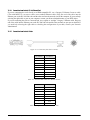
1.3.1
Annunciators
Table 1-4 shows a list of the annunciators that the DC-200/300 uses to provide additional information about the
value being displayed. The annunciators are illuminated when the specific function is being performed.
Annunciator
0
Annunciator Meaning
Gross weight is zero
NET
Display shows net weight (when tare weight is entered or recalled)
RECOM
Unit weight is recomputing is possible
INSUFF
Net weight is below specified percentage of scale capacity
Memory indicator showing quantity accumulation is being done
IN
Inventory IN (for counting mode)
OUT
Inventory OUT (for counting mode)
PE
Paper end.
R
Scale is in Registration Mode, also referred to as Operation Mode. (see Section 1.2 for description of
modes)
S
Scale is in Programming Mode. (see Section 1.2 for description of modes)
X
Scale is in Report Mode. (see Section 1.2 for description of modes)
Z
Scale is in Service Mode. (see Section 1.2 for description of modes)
Table 1-4. DC-200/300 Annunciators and Function
1.3.2
Key Functions
The DC-200/300 features a full alphanumeric keyboard with many functions for managing inventory information
and scale operation. Table 1-5 lists the keys and key functions of the DC-200/300 keyboard and keypad (see
Figure 1-2 above).
Note: Some keys have different functions depending on what mode you are in, so be sure to check which mode is selected
before using them
Introduction
5
.
Key
Description
Turns the scale display on or off
to
Used to enter numeric values. When using the scale, first enter a numeric value, then press the
appropriate function key.
Allows cycling between the different modes:
• Operation Mode – weighing and counting operations
• Report Mode – print item, inventory, and shelf location reports
• Program Mode – entering item data, factory name
• Password Mode – password protecting certain operations
• Service Mode -setup and troubleshooting by an authorized dealer or technician
• Operation Mode – set and clear tare weights
• Program Mode – do an item test print
• Other Modes – used to select “No”
• Operation Mode – clear keyed-in data from the display starting with the last digit entered
• Other Modes – used to select “Yes”
Used to reset the scale to zero. Also used in conjunction with other keys to enter the maintenance
mode. The REZERO key does not function when the scale is in motion.
• Operation Mode - compute unit weight by sampling. Press the PIECES key after placing a
10-piece sample on the platform, or after using the numeric keypad to enter the sample size. On
multi-channel units, ensure that the correct scale is selected.
• Other Modes - escape the programming screen without saving data
Used to enter a known unit weight using the numeric keypad
• Operation Mode – accumulate the total quantity
• Program Mode – select an item to be programmed such as item code, factory name, or cycle
through set-point modes
• Report Mode – select the type of report to print
• SPEC Setting – move between SPEC numbers (low to high)
•
•
•
•
Program Mode –- select programming item such as item code, factory name
Report Mode – select report type
Other Modes – enter the delete function
SPEC Setting – move between SPEC numbers (high to low)
• Operation Mode – call up stored item code information and switch between item code inventory
IN and OUT modes
• Program Mode – store the programmed data
Enter numeric values containing a decimal point
Note: A numeric value must be entered before the decimal point. For example,.250 would be
entered as 0.250.
Feed label or receipt paper (DC-300 only)
Cycle between Scales A through C when using the DC-200/300 as a multi-scale system.
Table 1-5. DC-200/300 Key Functions
6
DC-200/300 Operation Manual
Key
Description
• Operation Mode – print a label or report
• Report Mode – print out a report
• Program Mode – enter information about an item into temporary memory
to
• Operation Mode – view item code data stored in memory
• Program Mode – enter alphabetic data
Move the cursor. Change the entry to the right. Also used to cycle forward between choices in SPEC
setting mode.
Move the cursor. Change the entry to the left. Also used to cycle backward between choices in
SPEC setting mode.
Select the top function or character of a desired character key
Select the bottom function or character of a desired character key, generally to quickly view the
values in different registers
Shift between code type for keyboard entry. Options are:
• P:KEY - enter the letter or number corresponding to the key pressed
• A:KEY ASCII code - select by entering the hex code for the character
• T:KEY Teraoka code - select by entering the numeric value for the character
See Section 12.6 on page 159 - Character Code Tables
Delete data
Insert data
Table 1-5. DC-200/300 Key Functions
Introduction
7
2.0
Installation
This section describes the procedure for the installation and setup of the DC-200/300 counting scale.
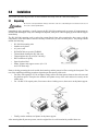
2.1
Unpacking
#AUTION
Do not turn scale upside down. Always work with scale on its side! Damage to the load cell can occur if
the scale is turned upside down.
Immediately after unpacking, visually inspect the DC-200/300 counting scale to ensure all components are
included and undamaged. If any were damaged in shipment, notify Rice Lake Weighing Systems and the shipper
immediately.
The DC-200/300 counting scale is packed in custom-fitted foam. After opening the box, remove all the
components. Check the insides of the box carefully to make sure you have all of the pieces. The package should
include the following:
• DC-200/300 counting scale
• Stainless steel platter
• AC power cord
• DC200/DC300 set-up tools CD-ROM
• Thermal head cleaning kit (DC-300 only)
• Thermal printer take-up reel (DC-300 only)
• DIGI certificate of quality
• Spare keysheet label
• Platter support and support screws (for 1 lb
and 2.5 lb units only)
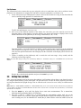
Remove the bag protecting the scale and the dessicant bag. and the protective film covering the front panel. The
rest of the unpacking/unlocking procedure depends upon the capacity of the scale.
• For units with capacities of 5 lbs or higher, simply remove the foam spacers between the scale case and
the platform spider. Then place the stainless steel platter on top of the scale and seat it securely on the
rubber stops.
• For 1 lb and 2.5 lb capacity units, first remove the two locking screws, then screw on the platter support.
Figure 2-1. Unlocking the Scale and Installing the Platter Support
• Finally, seat the stainless steel platter on the platter support.
After ensuring that all parts are present, store the original box in a safe location for possible future use.
8
DC-200/300 Operation Manual
2.2
Repacking
If the DC-200/300 counting scale must be returned for modification, calibration or repair, it must be properly
packed with sufficient cushioning materials. Whenever possible, use the original carton when shipping the
DC-200/300. Damage caused by improper packaging is not covered by the warranty.
2.3
Setting Up
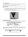
Place the scale on a solid, level surface away from fans, breezes, and sources of electrical interference.
Level the scale by turning the four adjustable legs located on the bottom of the scale while referencing the bubble
level located on the front of the scale (see Figure 2-2).
Note: To ensure a higher degree of scale stability, turn in all four adjustable legs before leveling. Turn out adjustable legs to level
as needed.
Figure 2-2. Leveling Feet and Bubble
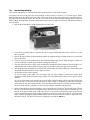
2.4
Powering Up the DC-200/300
After plugging the power cord into the socket on the bottom of the scale (Figure 2-3) turn the power switch on
the back of the bottom of the scale to the ON position. Generally when starting up the scale, if the power switch is
currently OFF, turning it to the ON position powers up the scale. If the power switch is already in the ON position
but the display has been powered down by pressing the ON/OFF key on the front, the scale can be reactivated by
pressing the ON/OFF key again.
Power cord
location
Power switch
location
Figure 2-3. Power Switch and Power Cord Location
Installation
9
Start-Up Screens
The instructions below assume that you are using the scale as a stand-alone unit, with or without remote
platforms. For information on using the DC-200/300 as a network workstation, see Section 11.0.
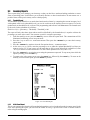
1. As the scale powers up it will display the current version of the firmware it is using. It also shows that the
scale is currently being operated as a stand-alone unit.
The DC-200 will show DC-200 Version X.XX.
2. After a test of the different elements of the display, the scale takes you to the stand-by screen in the
Operation Mode. At the stand-by screen the WEIGHT, UNIT WEIGHT and QUANTITY displays show zeroes
and the annuciator for the platform you are using is illuminated (A, B, C or D).
From this stand-by screen all of the basic weighing, counting and inventory operations can be performed
(See Section 6.0 on page 49). Also, if any job sequence instructions have been programmed into the
scale, the first operator instruction will be displayed on the second line of the display (See Section 8.0 on
page 103).
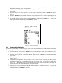
3. If there is anything on the platform(s) and it exceeds the scale start range, a beep sounds, and the
following error message appears.
Note: The Initial Start Range settings are controlled by SPEC 631. The default setting is 0: +UNLIMITED TO 10% OF FULL
SCALE.
Remove the weight from the platform and press the CLEAR key to exit.
2.5
Setting Time and Date
Once you set the internal clock for the correct day and time it will continue to keep them, even when the scale is
off, using the internal battery on the main board. The procedure below can also be used to adjust the time when
moving from Standard to Daylight Savings Time or when the scale is moved to a new facility in a different time
zone.
Note: SPEC 05 - DATE ORDER and SPEC 06 - TIME FORMAT allow you to set the format for date and time that you prefer the
scale to display. The defaults are Month/Date/Year for date and 12 hour for time. To change these specifications, see Customer
Specifications in Chapter 3.
1. Press the MODE key twice until the display shows ITEM CODE PROGRAMMING. The S annunciator,
indicating the Programming Mode, will illuminate.
2. Press the + (plus) or – (minus) keys to scroll through the programming options until you see the
PROGRAM DATE screen. Enter the current date using the numeric keypad. For months or days from 1 to 9,
enter a leading zero. (Ex. In a MM-DD-YY format, May 8, 2004 would be entered as 050804.) Press the
10
DC-200/300 Operation Manual
key to store the data in temporary memory and move to the time programming mode.
3. Enter the current time using the numeric keypad. For numbers from 1 to 9, enter a leading zero. (Ex. In a
12 hour format, 3:06 pm would be entered as 0306.) If SPEC 06 - TIME FORMAT is set to a 12 hour
format, you use the << and >> keys to toggle between AM and PM.
4. Press the CODE key to save the data or press the PIECES key followed by the CLEAR key to exit without
saving the data.
5. To return to the Stand-by Screen in the Operation Mode, press the MODE key three times.
REPRINT
2.6
Battery Installation (DC-200 only)
This section covers the installation of the DC-200’s battery into the battery compartment. Use the following steps
to install a battery into the DC-200.
#AUTION
Do not turn the scale upside down. Always work with the scale on its side! Damage to the load cell can
occur if the scale is turned upside down.
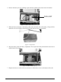
1. Turn the DC-200 on its left side.
2. Unscrew the three screws holding on the side cover to the battery compartment.
Screw Location
Figure 2-4. DC200 Screw Location
3. Remove the side cover enclosing the battery compartment.
Side Cover
Figure 2-5. Side Cover Location
Installation
11
4. Remove the battery slot screw holding in place the battery holder bracket, then remove the bracket.
Battery Holder
Bracket Location
Figure 2-6. Battery Holder Bracket Location
5. Slide the faston connectors on the battery cables onto the faston tabs on the battery, being careful to
match the wire color with the colored tag by the faston tabs to insure correct polarity.
Figure 2-7. Faston Tabs
6. Place the battery inside the battery compartment. Then replace the battery holder bracket and secure it
with the battery slot screw.
Figure 2-8. Battery Holder Bracket
7. Replace the side cover to the scale case and secure it with the three screws on the bottom of the scale.
12
DC-200/300 Operation Manual
3.0
Configuration Settings
This section presents the setup and configuration of the DC-200/300 counting scale to be used specifically by
distributors and service technicians. Configuring these specifications allow you to tailor the DC-200/300 to your
specific applications.
Setting the specifications allows you to modify the functionality of the DC-200/300. Use the tables in this section
to view the options you can modify. For example, if you want the function allowing you to print labels by
pressing the +/- keys as well as pressing the * REPRINT key to work on the DC-200/300, refer to the DC-200/300
specification table and locate SPEC 34 - PRINT WHEN PRESS +/- KEY. The default for SPEC 34 is 0, which means
that the PRINT WHEN PRESS +/- KEY function is turned off or disabled. To turn it on or enable it, change the SPEC
setting to 1.
3.1
Configuring Specification 141 and 142 Settings from the Scale Keyboard
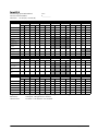
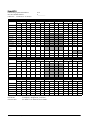
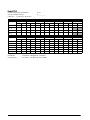
The following tables list the DC-200/300 specifications and their corresponding default values. The default
values are automatically set when the scale’s memory is set by the dealer for the country of operation.
SPEC 00 through SPEC 60 (Table 3-1) are customer specifications and use the 141 access code, while SPEC 600
through SPEC 646 (Table 3-2) are weight and measurement specifications, and use the 142 access code. In
programming specifications, the * REPRINT and – (minus) keys allow you to move to the next or previous
specification without saving changes to the SPEC code you were just in.
3.1.1
Customer Specification (141 Settings)
1. To configure customer specifications, press and hold the REZERO key and enter 141 using the numeric
keypad. The first SPEC code, SPEC 0 is displayed, with SP0: AUTO POWER SAVING appearing in the first
line of the weight display and its current setting (ex. 00>0: Disable) appearing in the second line.
If this is the SPEC that you want to modify, press >> or << keys to scroll through the possible settings.
When the setting you want to store is displayed, press the + (plus) key to enter the change into temporary
memory and move to the next SPEC code.
2. If you want to modify a SPEC other than SPEC 00 and you know the number of that SPEC code, enter
the number of the SPEC code on the numeric keypad and press the * REPRINT key. Otherwise, you can
use the + (plus) and – (minus) keys to scroll through the specifications until you find the one you want.
Then make your changes per the instructions in Step 1.
3. To change another SPEC code before exiting, repeat Steps 1 and 2.
4. To save all the changed SPEC settings currently in temporary memory and exit to the Operation Mode,
press the CODE key. You will hear a long beep to confirm that the scale is saving the change. The saving
of the configuration file takes about 10 seconds, after which the scale will return to the Stand-By mode.
To exit to the Operation Mode without saving the changes, press the TARE key.
#AUTION
If you power off the scale while the saving process in going on, you can clear the entire memory of the
scale! Wait until the scale has returned to the Stand-by screen before performing any other functions.
5. Power down scale using the power switch on the back of the bottom of the scale, not the ON/OFF key on
the keyboard.
6. Power scale on to re-initialize the new specification settings.
Configuration Settings
13
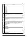
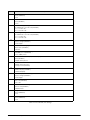
SPEC
Description
00
Auto Power Saving When No Weight Change & No Key Press
0: Disable (DEFAULT)
1: 1 minute
2: 2 minutes
3: 3 minutes
4: 4 minutes
5: 5 minutes
6: 6 minutes
7: 7 minutes
8: 8 minutes
9: 9 minutes
10: 10 minutes
11: 11 minutes
12: 12 minutes
13: 13 minutes
14: 14 minutes
15: 15 minutes
01
Power Saving Type
When set to 0, the backlight turns off when the scale goes into power-saving mode. When set to 1,
the scale turns off entirely
0: Backlight Off (DEFAULT)
1: Power Off
02
Negative Counting
0: No
1: Yes (DEFAULT)
03
Extent of Insufficient Samples
Sets the percentage of the full scale capacity that the initial counting sample has to exceed, otherwise
the INSUFF lamp lights.
0: 0.1% (DEFAULT)
1: 0.2%
2: 0.0%
04
Set New Item Code During Registration (Operation) Mode
This allows you to add item codes while weighing in the Operation Mode without having to switch to
the programming mode. These item codes can then be saved to the scale’s item code memory (by
choosing 0: Allow - Save); or ou can enter Item Codes, Part Names, and Lot Numbers that will print on
labels but not be saved to the item code memory (1: Allow - Not Save); or not allow items code and
item information to be set unless you are in the programming mode (2: Not Allow).
0: Allow (Save) (DEFAULT)
1: Allow (Not Save)
2: Not Allow
05
Date Order
0: Month/Day/Year (DEFAULT)
1: Day/Month/Year
2: Year/Month/Day
06
Time Format
0: 24 hour (DEFAULT)
1: 12 HOUR (am/pm)
07
Unit Weight Auto Recomputing
0: No (DEFAULT)
1: Yes
08
Sampling Times for Unit Weight Calculation
Higher number samples improve accuracy in environments of higher vibration or breeze but also
increase the time required to compute the unit weight.
0: 15 times (DEFAULT)
1: 20 times
Table 3-1. DC-200/300 (141) Settings
14
DC-200/300 Operation Manual
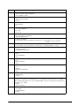
SPEC
Description
09
Display Accuracy Unit Weight Calculation During Recomputing
0: No (DEFAULT)
1: Yes
10
Set Point Buzzer
0: Buzzer on (DEFAULT)
1: Buzzer off
11
Clear All Input Key in One Touch
0: Yes
1: No (DEFAULT)
12
Keep Lot Number in Registration (Operation) Mode
0: Allow (DEFAULT)
1: Inhibit
13
Job Sequence
0: Disable (DEFAULT)
1: Enable
14
Auto Exit From Add Mode
0: No
1: Yes (DEFAULT)
15
SIO Select Job
Defines what the primary or standard input/output port on the scale is connecting to.
0: No operation (DEFAULT)
1: Not Used
2: PC
3: Printer
4: Bar Code Scanner
16
RS-232C Baud Rate (SIO - Standard Input/Output Port)
0: 1200 baud
1: 2400 baud
2: 4800 baud
3: 9600 baud (DEFAULT)
4: 19200 baud
5: 38400 baud
17
RS-232C Data Length (SIO - Standard Input/Output Port)
0: 7 bits
1: 8 bits (DEFAULT)
18
RS-232C Parity Bit (SIO - Standard Input/Output Port)
0: None (DEFAULT)
1: Odd
2: Even
19
RS-232C Stop Bit (SIO - Standard Input/Output Port)
0: 1 bit (DEFAULT)
1: 2 bits
20
RS-232 Option Card
0: Not connected (DEFAULT)
1: Not Used
2: Not Used
3: Printer/PC
4: PC/Printer
5: Not Used
6: Not Used
Table 3-1. DC-200/300 (141) Settings
Configuration Settings
15
SPEC
Description
21
RS-232 Baud Rate for 8 Pin DIN 1 Connector
0: 4800
1: 9600 (DEFAULT)
2: 19200
3: 38400
22
RS-232 Data Length for 8 Pin DIN 1 Connector
0: 7 bits
1: 8 bits (DEFAULT)
23
RS-232 Stop Bit for 8 Pin DIN 1 Connector
0: 1 bit (DEFAULT)
1: 2 bits
24
RS-232 Parity Bit for 8 Pin DIN 1 Connector
0: None (DEFAULT)
1: Odd
2: Even
25
RS-232 Baud Rate for 8 Pin DIN 2 Connector
0: 4800
1: 9600 (DEFAULT)
2: 19200
3: 38400
26
RS-232 Data Length for 8 Pin DIN 2 Connector
0: 7 bits
1: 8 bits (DEFAULT)
27
RS-232 Stop Bit for 8 Pin DIN 2 Connector
0: 1 bit (DEFAULT)
1: 2 bits
28
RS-232 Parity Bit for 8 Pin DIN 2 Connector
0: None (DEFAULT)
1: Odd
2: Even
29
Not Used
30
Not Used
31
PC/PRN Output Data Method
0: No operation
1: Counting
2: By +/-/Print Key (PC/PRN) (DEFAULT)
3: For both classes 1 & 2
32
Select External Printer Type (LP2824)
0: Eltron LP2622/LP2722 or TVP1000 (DEFAULT)
1: SE250 or (BCP300)
2: DP122 (Japan)
3: EPSON Output
33
External Eltron/TVP Printer Download Label Format
0: Enable (DEFAULT)
1: Disable
34
Print When Press +/- Key
0: Disable (DEFAULT)
1: Enable
35
PC Data With Header
0: Yes (DEFAULT)
1: No
Table 3-1. DC-200/300 (141) Settings
16
DC-200/300 Operation Manual
SPEC
Description
36
PC Data Header Type
0: Code 9 - numeric headers (DEFAULT)
1: Title - alphabetic headers
37
IBM Keyboard Port
0: IBM Keyboard (DEFAULT)
1: Scanner
38
Barcode Scanner (BCS) With Header
0: Yes (DEFAULT)
1: No
39
Track Nprint (TNP) Time Out
0: 2 seconds (DEFAULT)
1: 8 seconds
2: 32 seconds
40
Selection of Network Interface
0: No network (RS-232) (DEFAULT)
1: Twisted Cable (Ethernet)
41
Port Number (IP Address)
The port number can be set anywhere in a range from 1 to 255 (DEFAULT = 001 for DC-300)
(DEFAULT = 002 for DC-200)
42
Set Scale Number
The scale number can be set anywhere in a range from 0 to 999999 (DEFAULT = 00001)
43
Select Receipt or Label Paper Printing (DC-300 only)
0: Print paper receipt
1: Print label paper (DEFAULT)
44
Printing Speed For Receipt (DC-300 only)
0: Slow
1: Normal (DEFAULT)
2: High
45
Printing Speed for Label (DC-300 only)
0: Slow
1: Normal (DEFAULT)
2: High
46
Label Printing Density (DC-300 only)
0: Low
1: Medium
2: Medium High (DEFAULT)
3: High
47
Label Type (DC-300 only)
0: Gap (DEFAULT)
1: No Gap
48
Peel Sensor Function (DC-300 only)
The peel sensor determines whether labels are set to be printed with the backing left on (0: disable) or
with the backing peeled part way so that an individual label can be removed easily from the backing for
immediate use (1: enable).
0: Disable
1: Enable (DEFAULT)
49
Number of Reprint Labels (DC-300 only)
0: No Reprint
1:1 Label (DEFAULT)
2:2 Labels
Table 3-1. DC-200/300 (141) Settings
Configuration Settings
17
SPEC
Description
50
Selection of Label and Receipt Printing Operation
0: All operation (in/out/non-add) (DEFAULT)
1: Out (shipping operations)
2: In (receiving operations)
3: In and out
4: No printing
51
Human Readable Barcode Printing Format
0: No print (DEFAULT)
1: Print
52
Item Data Printing Format (DC-300 only)
Sets the justification for printing the data associated with item codes in memory such as ID codes, part
name, part number, and lot number
0: Centering
1: Start printing from the left (DEFAULT)
53
Date Title Print (DC-300 only)
0: No
1: Yes (DEFAULT)
54
Weight Data and Quantity Title Print (DC-300 only)
0: No print
1: Print (DEFAULT)
55
Printing of Factory Name on Label (DC-300 only)
0: No print
1: Print (DEFAULT)
56
Default Printing Label Factory Number (DC-300 only)
Can choose a factory number in a range from 0 to 32. (DEFAULT = 01)
57
Printing of Factory Name Format (DC-300 only)
0: No centering
1: Centering (DEFAULT)
58
Selection of Label Logo Printing Status (DC-300 only)
0: No print (DEFAULT)
1: Logo 1
2: Logo 2
3: Logo 3
4: Logo 4
59
Selection of Barcode Type
0: Code 128A
1: Code 128B
2: EAN 128A
3: EAN 128B
4: CODE 39 (DEFAULT)
60
Auto Print Function
0: Between set point 1 and set point 2
1: Disable (DEFAULT)
61
Ethernet Function
0: No operation (DEFAULT)
1: Track N Print
2: Data Transfer Mode
62
RS232 - XON/XOFF
0: Disable (DEFAULT)
1: Enable
Table 3-1. DC-200/300 (141) Settings
18
DC-200/300 Operation Manual
SPEC
Description
63
Sample Quantity
Determines the number of pieces the scale assumes are on the platter when you press the PIECES
key to calculate the Unit Weight.
0: 10 pieces (DEFAULT)
1: 25 pieces
2: 50 pieces
3: 100 pieces
64
Scale A <–> B
Sets whether the unit weight determined by sampling on Scale A is automatically transferred to Scale
B or not.
0: Manual (DEFAULT)
1: Auto
65
Unit of Pcs Weight
Sets whether the unit weights are displayed per 1000 pieces or per 1 piece. For a further discussion of
the benefits of each option, please see Section 5.5.
0: 1000 pieces (DEFAULT)
1: 1 piece
66
Not Used
67
IMS
Determines whether or not the scale automatically queries the DIGI Inventory Management Software
(IMS) for all of the parameters associated with an Item Code when the CODE key is pressed. For more
information on this option, please see Section 5.10.1.
0: Disable (DEFAULT)
1: Enable
68
EPSON II
Changes the Epson label format from the default (all item information fields) to an abbreviated format
with only selected fields.
0: Disable (DEFAULT)
1: Enable
69
4 Lot No.
If disabled, allows a single lot number to be entered during weighing operations. If enabled, allows up
to 4 lot numbers to be entered. These lot numbers are not written to the item database.
0: Disable (DEFAULT)
1: Enable
70
Upload Lot and Part Number
If disabled, lot numbers and part numbers entered during weighing operations are not uploaded to the
item database. If enabled, lot numbers and part numbers entered during weighing operations
overwrite the information previously stored with the item code in the scale memory.
0: Disable (DEFAULT)
1: Enable
71
Text 11-16 TTL
Allows you to use text fields 11-16 on total labels rather than just item labels.
0: Disable (DEFAULT)
1: Enable
72
Comma in Quantity
Enabling this option prints a comma after the first three places in a Quantity field on a user
programmed free label format. This allows a large quantity number to be read more easily at a glance.
Does not fit on the standard label format.
0: Disable (DEFAULT)
1: Enable
Table 3-1. DC-200/300 (141) Settings
Configuration Settings
19
SPEC
Description
73
Print Barcode
This option allows you to print barcodes on labels with all headers printed, with no headers printed, or
with all headers except the header for the Quantity barcode.
0: With Header (DEFAULT)
1: All Without Header
2: Quantity Without Header
74
Overwrite Unit Weight
Allows you to protect the Unit Weight so that it cannot be overwritten by the operator.
0: No (DEFAULT)
1: Yes (If Unit Weight = 0)
Table 3-1. DC-200/300 (141) Settings
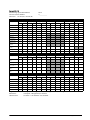
3.1.2
Weight and Measurement Specification (142 Settings)
1. Press and hold the REZERO key and enter 142 using the numeric keypad. SP600 appears in weight display
and its current setting (ex. 2>2: LB) appearing in the second line. If this is the SPEC that you want to
modify, press the >> or << keys to scroll through the possible settings. When the setting you want to store
is displayed, press the + (plus) key to enter the change into temporary memory and move to the next
SPEC code.
2. If you want to modify a SPEC other than SPEC 600 and you know the number of that SPEC code, enter
the number of the SPEC code on the numeric keypad and press the *REPRINT key. Otherwise, you can
use the + (plus) and – (minus) keys to scroll through the specifications until you find the one you want.
Then make your changes per the instructions in Step 1.
3. To change another SPEC code before exiting, repeat Steps 1 and 2.
4. To save all the changed SPEC settings currently in temporary memory and exit to the Operation Mode,
press the CODE key. To exit to the Operation Mode without saving the changes, press the TARE key.
5. Power down scale using the power switch on the back of the bottom of the scale, not the ON/OFF key on
the keyboard.
6. Power scale on to re-initialize the new specification settings.
Spec
Description
600
Scale Unit Specification
0: Gram
1: Kg
2: Lb (DEFAULT)
601
Display Resolution
0: 1/10000 (DEFAULT)
1: 1/5000
2: 1/2500)
602
Internal Count
0: 500,000
1: 1,000,000 (DEFAULT)
603
Minimum Display (Increment) for Scale A
0: 2 (DEFAULT)
1: 1
2: 5
3: 10
Table 3-2. DC-200/300 (142) Settings
20
DC-200/300 Operation Manual
Spec
Description
604
Weight Decimal Point Position for Scale A
0: 0
1: 0.0
2: 0.00
3: 0.000 (DEFAULT)
4: 0.0000
605
Load Cell Sensitivity Selection in mV/V for Scale A
0: 4.00 mV/V
1: 3.76 mV/V
2: 3.52 mV/V
3: 3.28 mV/V
4: 3.04 mV/V
5: 2.80 mV/V
6: 2.56 mV/V
7: 2.32 mV/V
8: 2.08 mV/V
9: 1.84 mV/V
10: 1.60 mV/V
11: 1.36 mV/V
12: 1.12 mV/V (DEFAULT)
13: 0.88 mV/V
14: 0.64 mV/V
15: 0.40 mV/V
606
Load Cell Type for Scale A
0: Standard / Normal load cell (DEFAULT)
1: Abnormal load cell with large offset
607
A/D Board Type for Scale A
0: Normal (DEFAULT)
1: Prevent from small vibration / fast change in display
2: Prevent from medium vibration
3: Prevent from large vibration / slow change in display
608
External Scale B Connection
0: Disable (DEFAULT)
1: Enable
609
Minimum Display (Increment) for Scale B
0: 2 (DEFAULT)
1: 1
2: 5
3: 10
610
Weight Decimal Point Position for Scale B
0: 0
1: 0.0
2: 0.00
3: 0.000
4: 0.0000 (DEFAULT)
Table 3-2. DC-200/300 (142) Settings
Configuration Settings
21
Spec
Description
611
Load Cell Sensitivity Selection in mV/V for Scale B
0: 4.00 mV/V
1: 3.76 mV/V
2: 3.52 mV/V
3: 3.28 mV/V
4: 3.04 mV/V
5: 2.80 mV/V
6: 2.56 mV/V
7: 2.32 mV/V
8: 2.08 mV/V
9: 1.84 mV/V
10: 1.60 mV/V
11: 1.36 mV/V
12: 1.12 mV/V (DEFAULT)
13: 0.88 mV/V
14: 0.64 mV/V
15: 0.40 mV/V
612
Load Cell Type for Scale B
0: Standard / Normal load cell (DEFAULT)
1: Abnormal load cell with large offset
613
A/D Board Type for Scale B
0: Normal (DEFAULT)
1: Prevent from small vibration / fast change in display
2: Prevent from medium vibration
3: Prevent from large vibration / slow change in display
614
External Scale C Connection
0: Disable (DEFAULT)
1: Enable
615
Minimum Display Increment for Scale C
0: 2
1: 1 (DEFAULT)
2: 5
3: 10
616
Weight Decimal Point Position for Scale C
0: 0 (DEFAULT)
1: 0.0
2: 0.00
3: 0.000
4: 0.0000
Table 3-2. DC-200/300 (142) Settings
22
DC-200/300 Operation Manual
Spec
Description
617
Load Cell Sensitivity Selection in mV/V for Scale C
0: 4.00 mV/V
1: 3.76 mV/V
2: 3.52 mV/V
3: 3.28 mV/V
4: 3.04 mV/V
5: 2.80 mV/V
6: 2.56 mV/V
7: 2.32 mV/V
8: 2.08 mV/V
9: 1.84 mV/V (DEFAULT)
10: 1.60 mV/V
11: 1.36 mV/V
12: 1.12 mV/V
13: 0.88 mV/V
14: 0.64 mV/V
15: 0.40 mV/V
618
Load Cell Type for Scale C
0: Standard / Normal load cell (DEFAULT)
1: Abnormal load cell with large offset
619
A/D Board Type for Scale C
0: Normal (DEFAULT)
1: Prevent from small vibration / fast change in display
2: Prevent from medium vibration
3: Prevent from large vibration / slow change in display
620
Tare Range Settings
0: 100% full scale (DEFAULT)
1: <50% full scale
2: <5% full scale
621
Digital Tare Setting
0: Disable
1: Enable (DEFAULT)
622
Tare Accumulation
0: No (DEFAULT)
1: Yes
623
Digital Tare When Loaded
0: Allow (DEFAULT)
1: Inhibit
624
Tare Subtraction (for Load Tare Only)
0: Yes (DEFAULT)
1: No
625
Tare Addition (for Load Tare Only)
0: Yes
1: No (DEFAULT)
626
Tare Value Exchange (for Load Tare)
0: Yes (DEFAULT)
1: No
627
Zero Tracking When Tare
0: Yes (DEFAULT)
1: No
628
Tare When Scale Change
0: Old Tare (DEFAULT)
1: New Tare
Table 3-2. DC-200/300 (142) Settings
Configuration Settings
23
Spec
Description
629
Weight Reset When Tare
0: Yes (DEFAULT)
1: No
630
Auto Clear Tare When Rezero
0: No (DEFAULT)
1: Yes
631
Initial Start Range Settings
0: +Unlimited to 10% full scale (DEFAULT)
1: +/- 2% full scale
2: +/- 10% full scale
632
Zero Range Settings
0: +Unlimited to 10% full scale (DEFAULT)
1: +/- 2% full scale
2: +/- 10% full scale
633
Zero Lamp Lighting Method
0: Gross weight (DEFAULT)
1: Net weight
634
Rezero When Changing Scale
0: No rezero (DEFAULT)
1: Rezero
635
Stability Check When Changing Scale
0: Stability check (DEFAULT)
1: No stability check
636
Internal Count Resolution (IR) Protected by Span Switch
0: No (DEFAULT)
1: Span switch protect
637
Calibration/Default SPEC/SPEC 142 Mode Protected by Span Switch
0: Span switch protection
1: No protection (DELETE)
638
Display at Minus Weight
0: Minus display (DEFAULT)
1: Masked display
639
Masked Display at Minus Weight
0: Gross weight (DEFAULT)
1: Net weight
640
Overweight Masked
0: At +1D (DEFAULT)
1: At + 9D
641
Selection of Scale Starting Method
0: Auto start (DEFAULT)
1: Manual start
642
Weight Unit Convert
0: Yes (DEFAULT)
1: No
643
Gross Mode Display
0: Yes (DEFAULT)
1: No
Table 3-2. DC-200/300 (142) Settings
24
DC-200/300 Operation Manual
Spec
Description
644
Selection of Decimal Point Type
Sets whether the decimal point is displayed as a period (U.S. usage) or a comma (European, Latin
American, Asian usage)
0: Period display (DEFAULT)
1: Comma display
645
Selection of Scale Type
0: DC-300 scale
1: DC-200 scale
646
Automatic Unit Weight Clear Conditions
0: Disable (DEFAULT)
1: Over net 5D & gross 21D & weight stable
2: >=net 1D & weight stable
3: >=net 1D & quantity > 0 & weight stable
Table 3-2. DC-200/300 (142) Settings
3.2
Configuring Spec 141 and 142 Settings Using the Spec Upload Utility
The DC-300 Utility Program includes a module called “Spec Upload”. This handy program allows you to more
easily do four useful things:
• change one or any number of spec settings from your computer screen and then upload them to a
DC-200/300 rather than change them from the scale’s keyboard.
• save the spec setting currently programmed in the DC-200/300 to a named file on your computer from
which they can be restored to the same DC-200/300 later or uploaded to other DC-200/300s so that their
spec settings match.
• save spec settings optimized for a particular task, department or facility to a named file on the computer.
This complete set of spec settings can then be uploaded to a DC-200/300 whenever the scale’s use or
location changes, rather than have to go through and manually change each spec. It can also be used to
save a backup of your spec settings if you should need to send your scale to be serviced.
• return all the scale’s spec settings to the default settings by uploading the defaults from the computer to
the scale.
Note: For information on how to install the DC-300 Utility Program on your computer, See Section 6.2.2 on page 54 If you have
not already set up your computer and the scale to be able to communicate to each other using the DC-200/300’s Ethernet
connection, please see Section 11.0. If you are unsure of how to work with TCP/IP connections or have difficulties, see your
Network Administrator for help.
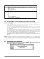
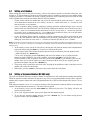
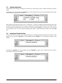
3.2.1
Change Spec Settings Using the Spec Upload Utility
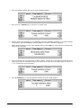
1. With the scale turned on and at the Stand-by screen, press REZERO + SHIFT UP. The scale display will
indicate that it is changing to the data transfer mode.
Configuration Settings
25
2. The scale display will next indicate that it is ready for the data transfer mode after the scale is restarted.
Turn the scale off and then on again, using the on/off switch located on the bottom of the scale at the
back.
3. After you restart the scale and it goes through its startup sequence, the scale will show that the data
transfer mode is ready.
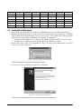
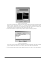
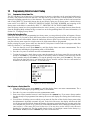
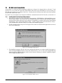
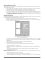
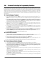
4. On your computer, open the Spec Upload program.
Note: If you have not yet installed the DC-300 Utility Program, see Section 6.2.2 on page 54.
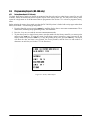
At the opening screen of the Spec Upload program, you have the option to Load the Default Setting file; load
from a named, saved file on your computer; or read the spec settings from the DC-200/300 scale connected to
your computer.
Select the radio button for Read From Scale. Also make sure that the Scale No. radio button for 192.168.0.1 (the IP
address of the DC-300) has been selected if you are using the DC-300 or 192.168.0.2 if you are using the
DC-200.
Figure 3-1. Read From Scale Screen
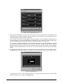
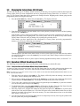
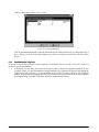
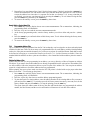
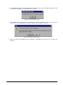
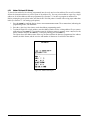
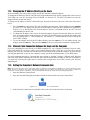
5. Click on the Next button at the bottom of the Spec Setting dialog box. The program will confirm Spec
reading in progress, please wait..., showing that it is uploading the current spec settings from the scale. The
Spec Upload program will next display the Spec Setting screen, showing the values of the first four
SPECs programmed in the scale.
26
DC-200/300 Operation Manual
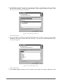
Figure 3-2. User Specification Screen
6. To change the setting of one or more of the first four specs, use the pull down list box for that spec to
choose among the available settings for that specification. To move to the next four specifications, click
on the Next button at the bottom of the dialog box.
7. Once you have made all the needed changes to the specifications, you can upload the changed specs to
the scale and also save the new configuration to a named file on your computer for future updating of this
scale or matching the specifications on another DC-200/300 (Section 3.2.2 on page 29).
To save the new configuration settings, click on the Save button at the bottom of the dialog box. You will
be prompted to give this configuration a file name. The next time you open the DC-300 Spec Upload
program, this file will show as one of the ones available to upload to any DC-200/300. After assigning a
file name, click on the Save button to save the file. You will be returned to the main Spec Upload Utility
screen.
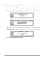
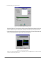
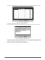
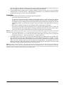
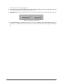
8. To upload the changed spec settings to the DC-200/300 currently connected to your computer, click on
the Upload button. The utility will ask you whether you want to update one specific spec or all the specs.
Figure 3-3. Upload Screen
To update only one spec, type its number into the box. To update all the specifications, select the radio
button for All Specifications. Click on the Upload button.
Configuration Settings
27
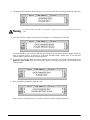
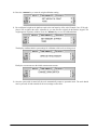
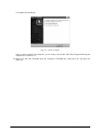
9. The program will confirm with the message Successfully Sent while the scale display shows the following.
7ARNING
If you power off the scale while the saving process in going on, you can clear the entire memory of the
scale!
Once the scale has completed the upload of the change(s), it will display the following:
The scale should be powered down and then powered back up to initialize the new changes. When the
scale is powered back up, it will still be in the DATA TRANSFER MODE - READY state. To exit the Data
Transfer Mode, continue with the instructions below.
10. To exit the Data Transfer Mode on your DC-200/300 scale and return it to normal weighing mode, press
REZERO + SHIFT DOWN . The scale will briefly display a message saying that it is exiting the Data
Transfer mode.
11. Next you will be prompted to restart the scale.
Once you have restarted the scale, you will be returned to normal weighing operations.
28
DC-200/300 Operation Manual
3.2.2
Uploading Saved Spec Configurations to a DC-200/300
To download the spec settings from a DC-200/300 to the computer, see Section 3.2.1. If you already have a
saved configuration file of spec settings, use the instructions below to upload the settings to a DC-200/300. This
could be to change the settings of a DC-200/300 to fit a particular task, department or facility or it could be to
take the spec settings configuration from one DC-200/300 and upload it to other DC-200/300’s so that their
settings match.
1. With the scale turned on and at the Stand-by screen, press REZERO + SHIFT UP. The scale display will
indicate that it is changing to the data transfer mode.
2. The scale display will next indicate that it is ready for the data transfer mode after the scale is restarted.
Turn the scale off and then on again, using the on/off switch located on the bottom of the scale at the
back.
3. After you restart the scale and it goes through its startup sequence, the scale will show that the data
transfer mode is ready.
4. On your computer, open the Spec Upload program.
Configuration Settings
29
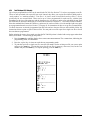
Note: If you have not yet installed the DC-300 Utility Programs, see “Installing the DC-300 Utility Program”.
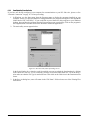
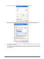
Figure 3-4. Load From File Screen
At the opening screen of the Spec Upload program, you have the option to Load the Default Setting file; load
from a named, saved file on your computer; or read the spec settings from the DC-200/300 scale connected to
your computer.
• to load the default specification settings to the scale, click the radio button next to Load Default Setting.
When you installed the DC-300 Utility Program a file named Default.ini was copied into the Digisoft
folder on your computer. To see what the default settings are for the scale specifications, see Section 3.1.
• to load a specification file you have previously saved to your computer, select the radio button for Load
From File. If the named file you want to upload to the scale appears in the File Name box, click on it to
select it. If the file you want does not appear in the File Name box, use the Drives and Folders explorer
windows to find the file you are looking for.
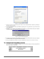
Once you have selected the spec configuration file to be uploaded and it appears under File Name, click on
the Next button at the bottom of the screen to continue.
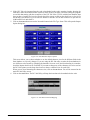
5. In the next screen you have the option to change any of the spec settings saved in this file before
uploading.
Figure 3-5. User Specification Screen
To upload to the scale without making any changes, click on the Upload button. To change the setting of
one or more of the first four specs, use the pull down list box for that spec to choose among the available
30
DC-200/300 Operation Manual
settings for that specification. To move to the next four specifications, press the Next button at the bottom
of the dialog box.
6. Once you have made all the needed changes to the specifications, you can upload the changed specs to
the scale and also save the new configuration to a named file on your computer for future updating of this
scale or matching the specifications on another DC-200/300 (Section 3.2.2).
To save the new configuration settings, click on the Save button at the bottom of the dialog box. You will
be prompted to give this configuration a file name. The next time you open the DC-300 Spec Upload
program, this file will show as one of the ones available to upload to any DC-200/300. After assigning a
file name, click on the Save button to save the file. You will be returned to the main Spec Upload Utility
screen.
7. To upload the changed spec settings to the DC-200/300 currently connected to your computer, click on
the Upload button. The utility will ask you whether you want to update one specific spec or all the specs.
To update only one spec, type its number into the box. To update all the specifications, select the radio
button for all specifications. Click the Upload button.
Figure 3-6. Upload Spec Settings
Configuration Settings
31
8. The program will confirm with the message Successfully Sent while the scale display shows the following.
7ARNING
If you power off the scale while the saving process in going on, you can clear the entire memory of the
scale!
9. Once the scale has completed the upload of the change(s), it will display the following:
The scale should be powered down and then powered back up to initialize the new changes. When the
scale is powered back up, it will still be in the DATA TRANSFER MODE - READY state. To exit the Data
Transfer Mode, continue with the instructions below.
10. To exit the Data Transfer Mode on your DC-200/300 scale and return it to normal weighing mode, press
REZERO + SHIFT DOWN. The scale will briefly display a message saying that it is exiting the Data
Transfer mode.
11. Next you will be prompted to restart the scale.
Once you have restarted the scale, you will be returned to normal weighing operations.
32
DC-200/300 Operation Manual
4.0
Calibration
The DC-200/300 counting scale is a high-precision instrument. Although the scale needs very little maintenance,
you may want to check the calibration after every month or so of normal usage. To do this you will need to have
a test weight of approximately the total capacity of the scale (i.e. a 10 lb weight if you have a 10 lb capacity
scale). After the scale is initially installed, put the weight on the platform and record the weight displayed. Then
every month or so put the same weight on the scale and verify that it still reads the same.
Many facilities have a technician come in and check their units with certified test weights four times a year. If
you are ISO certified, you will want to check to see if your certification specifies more stringent requirements to
stay in compliance. Your DIGI scale dealer has the calibrated test weights, expertise and experience to perform
this task for you as well as to check other operating parameters of your scale and help you effectively integrate
scales into your operations. If you do not know who your local DIGI dealer is, call us at 1-715-736-0002 and we
will help you find someone who can provide you with on-site support.
Follow the instructions below to calibrate your DC-200/300 scale to ensure its continued accuracy.
1. Make sure the scale is turned off. Then press the span switch to reset it. (See Figure 4-1 for location of
Span switch).
Figure 4-1. Location of Span Switch
2. Turn the scale back on. The scale displays the message CHANGE SPAN SWITCH.
3. While pressing the REZERO key, enter 8715 from the numeric keypad to enter the calibration mode.
Calibration
33
4. The scale display confirms that you are in the Calibration Mode.
5. Next, press the * REPRINT key to enter the zero setting mode.
6. Choose which scale platform you are calibrating. The scale defaults to platform A. To choose another
scale platform, press the SCALE key until the platform you want to calibrate is displayed.
7. Make sure that nothing is on the scale platform and press the CODE key to have the scale automatically
search for the zero point.
8. The scale displays the zero point in the quantity window. It should be a value between 9000 and 11000.
If the scale does not catch that range, you will need to call your local DIGI dealer or call us at
1-715-736-0002 for service assistance.
9. Press the REZERO key to clear the Internal Count shown in the weight window.
34
DC-200/300 Operation Manual
10. Press the * REPRINT key to enter the weight calibration setting.
11. Put a calibrated weight on the platform equal to the total capacity of the scale (Example, for a 25 lb scale,
place a 25 lb weight on the scale). Alternatively, you can enter the weight from the numeric keypad. The
weight appears in quantity window. Press the * REPRINT key to save the calibration data.
The display confirms that the span settings for calibration of the scale are being saved
Finally the screen returns to the initial CHANGE SPAN SWITCH.
12. Once the span switch is turned off, the scale automatically returns to operation mode. The scale should
now be powered off and restarted for the new settings to take effect.
Calibration
35
5.0
Scale Operations
The following paragraphs contain detailed operator instructions for the DC-200/300 counting scale (see
Figure 5-1). Included are instructions to enter tare weights, toggle between net and gross weight, enter unit
weights, perform inventory accumulation and reduction, and toggle between scales. All operator instructions are
conducted with the scale in the operation mode that is the weighing or normal mode.
Figure 5-1. DC-300 Counting Scale
Counting scale accuracy is primarily determined by the following factors:
• Sample size (number of pieces)
• Total sample size as a percentage of full scale capacity
• Piece-to-piece weight variation
As a general rule when determining sample size of fairly uniform pieces, the larger the sample size the greater
the total sample weight, therefore, the better the counting accuracy. Selecting the smallest capacity scale that can
obtain the highest counting resolution should be considered, but should not sacrifice the capacity required for the
heaviest container of parts. For this kind of application, a dual-platform scale may be the best selection.
There is a direct relationship between piece-to-piece weight variation (non-uniformity) and counting accuracy.
Therefore, elimination of the piece-to-piece weight variations can be accomplished by:
1. Isolating the sample used to calculate the unit weight and use the same sample to re-check the scale.
2. Recalculating the unit weight from lot-to-lot of parts. Parts manufactured on one machine may vary
slightly from another machine relative to weight.
3. Tightening the manufacturing tolerances on the parts reduces piece weight variations and increases count
accuracy.
The Stand-By Screen
The starting point for using the scale in operation mode is the stand-by screen. At the stand-by screen the WEIGHT,
UNIT WEIGHT, and QUANTITY displays show zeroes and the annuciator for the platform you are using is illuminated
(A, B, C or D).
From the stand-by screen you can perform all of the basic weighing, counting and inventory operations of the
scale.
36
DC-200/300 Operation Manual
5.1
Weight Unit Switching
Notes:
• SPEC 600 SCALE UNIT SPECIFICATION sets the default weight unit to Grams, Kgs or Lbs.
• SPEC 642 WEIGHT/UNIT CONVERT must be set to “0: YES” in order for you to be able to switch weight units during weighing
operations.
The weight units displayed can be changed between Kg and Lb during weighing operations by pressing the SHIFT
DOWN key followed by the N key.
5.2
Toggle Between Scales
To toggle between Scales A through D, press the SCALE key. The indicator lamp for the appropriate scale lights
on the display.
Pressing the SCALE key rotates the scales available for selection as follows:
4DBMF"4DBMF#4DBMF$
4DBMF%
Only scales present will be selected (i.e. A two-scale system switches between Scale A and Scale B only.) If no
external scales are connected, this function will not work.
5.3
Setting Tare Weights in Operation Mode
This section will describe the different tare-related operations you can perform from the operation mode. Tare
weight can be set by one touch tare using the TARE key or, if the value is known ahead of time, can be entered
digitally using the digital tare function. Tare addition and subtraction can also be done digitally or by using the
TARE key. Finally, an existing tare stored with an Item code can be overridden with a new one if needed.
Note: The following SPEC codes must be set properly to allow these operations before continuing: SPEC 620 TARE RANGE
SETTINGS sets the limit of the tare range. SPEC 621 DIGITAL TARE and SPEC 622 DIGITAL TARE ACCUMULATION must be
set to “1” to enable these functions. SPEC 623 DIGITAL TARE WHEN LOADED, SPEC 624 TARE SUBTRACTION FOR LOAD
TARE ONLY, SPEC 625 TARE ADDITION FOR LOAD TARE ONLY, and SPEC 626 TARE VALUE EXCHANGE (FOR LOAD TARE)
must all be set to “0” to enable these functions.
5.3.1
One Touch Tare (When the Tare Weight is Unknown)
1. While at the stand-by screen, place a bin, box or other weight to be tared out on the platform.
2. Press the TARE key to subtract the tare weight. The Net annuciator will light up and the weight display
should now show 0.
3. If you remove the tare weight from the platform, the tare weight will show as a negative weight in the
weight window and the Net annunciator will remain lit.
Note: This tare weight will be overridden by the weight stored with an item code if you call up an item code at this point.
4. To clear this tare weight and return to the operation mode, press the TARE key again. The net annunciator
will not longer be lit.
5.3.2
Digital Tare (When Tare Weight is Known in Advance)
1. While at the stand-by screen, enter the known tare weight by using the numeric keypad.
2. Press the TARE key to subtract the tare weight. The Net annunciator will light up and the tare weight will
be displayed in the weight display.
Note: This tare weight will be overridden by the weight stored with an item code if you call up an item code at this point.
3. To clear this tare weight and return to the operation mode, press the TARE key again. The net annunciator
will no longer be lit.
Note: For digital tare entry, the decimal must be in the appropriate place as it would be displayed in the weight display. For
example,.250 would be entered as 0.250, not.250. The weight display shows weight entered with a negative sign indicating that
it is a tare weight.
Scale Operations
37
5.3.3
Tare Addition or Subtraction
Two tares can be accumulated or subtracted using the TARE key as well. Tare weights cannot be accumulated or
subtracted by digital entry, although you can do tare exchange by digital entry (Section 5.3.2).
Notes:
• SPEC 620 TARE RANGE must be set to the appropriate tare range value. Default is “0: 100 PERCENT OF FULL SCALE”.
• SPEC 621 DIGITAL TARE SETTING must be a “1: ENABLE” to allow digital tare.
• SPEC 622 DIGITAL TARE ACCUMULATION must be set to “1: YES”.
• SPEC 623 DIGITAL TARE WHEN LOADED, SPEC 624 TARE SUBTRACTION FOR LOAD TARE ONLY, SPEC 625 TARE
ADDITION FOR LOAD TARE ONLY, and SPEC 626 TARE VALUE EXCHANGE (FOR LOAD TARE) must all be set to 0: ALLOW or
YES to enable these functions.
1. Place the container, box or item to be tared on the platform and press the TARE key. The weight display
should show 0 and the Net annunicator will illuminate.
2. Place another tare weight on the platform and press the TARE key again. This will add the two tare
weights together (Tare Addition).
3. Tare weights can be subtracted individually by removing one from the platform and pressing the TARE
key again. To clear all the tare weights and return to the operation mode, remove all the tare weights and
press the TARE key. The Net annunicator will no longer be lit.
5.3.4
Tare Exchange or Override
This function allows you to change the tare value during the operation mode. You can change the tare weight
without associating it with an item code, change the tare weight already associated with an item code while in
registration mode, or add a tare value to an existing item code if it doesn’t already have one. The new tare entered
will overwrite the previous tare.
1. Remove any bin or container from the scale.
2. To change the tare weight without recalling an Item Code, go to Step 3.
3. To change the tare weight associated with an item code, enter the item code for which you want to
change the tare value and press the CODE key. If there is already a tare weight associated with this item
code in memory, it will be displayed in the Weight Display window.
4. If the tare weight value is known, use the numeric keypad to key in the value and then press TARE. The
weight display will now show the new tare as a negative number and the Net annunciator will illuminate.
If the tare weight value is not known, put the container to be tared out on the platter and press the TARE
key. The new tare will be entered, the weight display will show 0.000 lb and the Net annunicator will
illuminate.
5. You may now either place the product on the platter for weighing and counting or press the CLEAR key to
return to the stand-by screen. To print a receipt or a label for the product, press the * REPRINT key while
the product is on the platter. To clear the tare weight just entered when you return to the stand-by screen,
press the TARE key again.
5.4
Toggling Between Gross and Net
To toggle between net and gross weight, a tare value must be entered into the scale. Follow Section 5.3 to enter a
tare value.
Note: SPEC 643 GROSS MODE DISPLAY must be set to 0: YES (which is the default) to enable gross mode.
After a tare value is entered into the scale, items placed on the scale will cause the net annunciator to illuminate
and allow toggling between net weight and gross weight. An example of toggling between net weight and gross
weight is shown below:
1. Place 0.5 lb weight on the scale and then press TARE once. The weight display should show 0.000 lb.
2. Place another 0.5 lb weight on the scale. The scale weight display should now show 0.500 and the net
annunciator should be illuminated.
3. Press SHIFT DOWN + NET/G. The weight display should show 1.000 GROSS WEIGHT, the net annunciator
will no longer be illuminated. The unit weight and the quantity displays go blank.
38
DC-200/300 Operation Manual
4. Press SHIFT DOWN + NET/G. The weight display should now show 0.500 and the net weight annunciator is
illuminated again.
5.5
Entering Unit Weights
Entering unit weights can be done either by sampling, as presented in Section 5.5.1, or by key entry as described
in Section 5.5.2.
Note: SPEC 03 EXTENT OF INSUFFICIENT SAMPLES controls unit weight sampling. The default setting for the SPEC is 0.1
percent.
Note: SPEC 63 SAMPLE QUANTITY determines the number of pieces the scale assumes are on the platter when you press the
PIECES key to calculate the unit weight. The default setting for the SPEC is 0: 10 pieces.
Note: SPEC 64 SCALE A <–> B sets whether the unit weight determined by sampling is automatically transferred from Scale A
to Scale B. The default setting for the SPEC is 0: MANUAL.
When you have a procedure that involves sampling an item’s unit weight on the DC-200/300’s built-in platform
and then want to go immediately to weighing and counting boxes or bins on a floor scale or other external scale,
set SPEC 64 to 1: AUTO. If the external Scale B is not necessarily going to be used for weighing the same item
as is being sampled on Scale A, set SPEC 64 to 0: MANUAL.
Note: SPEC 65 UNIT OF PCS WT controls whether the unit weight is displayed per 1000 pieces or per 1 piece. The default
settings for this SPEC is 0: 1000 pieces.
Unit Weight per 1000 Pieces vs. Unit Weight per 1 Piece
The scale’s internal microprocessor calculates unit weights to 7 or 8 decimal places. However, the scale display
generally can only show Unit Weight to 5 characters. If this Unit Weight is recorded from the scale display and
entered by key entry, this can introduce errors in the Unit Weight and consequently in the counts. This error
increases as the Unit Weight of the parts being counted decreases.
Example: A sample of 10 zener diodes is placed on the scale. The Unit Weight is computed to be 0.0006536 lbs.
However, the scale has a 5 character display for Unit Weight so the scale can only display.0065 as the Unit
Weight. If this Unit Weight were recorded and keyboard entered in future counting operations, the resulting error
would be:
00065
=.55%
.0006536
On the other hand, with entry of the Unit Weight as “weight per 1000 pieces” the decimal place is, in effect,
moved three places to the right, allowing 3 more decimal places of accuracy. In this example, the entry would be
made as 0.6536 per 1000 pieces, eliminating the error.
As a practical note, entering unit weights per 1000 pieces also lessens the chances of entering the wrong number
of zeros when keying in weights with many leading zeros. Misentry of unit weights is a common cause of
inaccurate counting.
Note also that when SPEC 65 Unit of Pcs Weight is set to 1: Unit Weight per 1 piece (this is also called “average
piece weight” or APW), the scale will not accept a sample that produces an APW of less than 0.01 lbs, regardless
of the scale capacity. If the APW is less than 0.01 lbs, the error message DATA INVALID will appear to warn the
operator that the part is too small to be counted using APW and that the unit weight/1000 pieces should be used
to count this piece. Remember that if average piece weight (unit weights per 1 piece) have been stored in
memory with an Item Code, these unit weights will not automatically be converted to unit weight per 1000 pieces
when the item is recalled from memory. If you are changing SPEC 65 to operate using unit weight per 1000
pieces, you should update the unit weights associated with item codes in memory or eliminate the unit weights in
memory and establish them by sampling or key entry at the time you recall the Item Code. (See Section 6.1.2 for
more information on how to program items into memory).
When might you want to use unit weight per 1 piece? Generally in one of two cases:
1. If you are working with other existing systems or procedures that are already set up to record unit weight
per piece (inventory systems, labeling requirements, etc).
2. If the unit weight or your pieces is more than 100 lbs, as in the case of some castings, engine parts and
the like. When the unit weight is over 100 lbs, the number of digits in the scale’s Quantity display will
not be able to fully display counts of more than 100 pieces.
Scale Operations
39
5.5.1
Unit Weight Operation by Sampling
Unit weight operation by sampling is accomplished by placing a 10 piece sample on the scale and then pressing
the PIECES key. The scale calculates a unit weight based on the capacity of the scale compared to the weight of
the sample. The following paragraphs detail the procedure with SPEC 7 - UNIT WEIGHT
AUTO-RECOMPUTING either set at 0 or 1.
SPEC 7 - Unit Weight Auto-Recomputing Set to “0: No” (Default)
1. Press REZERO to zero scale.
2. Place 10 pieces of the item to be sampled on the scale.
3. Press PIECES key. If the sample weight is sufficient (INSUFF annunciator is off), the display shows a unit
weight for 10 pieces. However, if the weight of the sample is insufficient (INSUFF annunciator is on) the
display will show ---ADD XX PIECES. Add the indicated number of pieces to the initial sample and then
press the PIECES key again.
4. The display shows the total weight, unit weight and the quantity of the sample.
SPEC 7 - Unit Weight Auto-Recomputing Set to “1: Yes”
1. Press REZERO key to zero scale.
2. Place 10 pieces of the item to be sampled on the scale.
3. Press the PIECES key. If the weight of the sample is sufficient (INSUFF annunciator is off), the display
shows a unit weight for 10 pieces. However, if the weight of the sample is insufficient ( INSUFF
annunciator is on) the display will show ---ADD XX PIECES. Add the indicated number of pieces to the
initial sample. The display then automatically recomputes the sample size and displays the unit weight
and quantity of the sample.
5.5.2
Unit Weight Operation by Key Entry
Unit weight operation by key entry is accomplished by using the numeric keypad to enter the known value of the
unit weight and then pressing the UNIT WEIGHT key. An example of unit weight operation by key entry is shown
below:
1. With the display in the weighing mode, enter the known unit weight using the keyboard, for example,
200.00.
2. Press UNIT WEIGHT key to enter the unit weight.
3. Place a 2 lb. weight on the scale. The scale displays the quantity for the weight placed on the scale, for
example, the weight display reads 2.000, the unit weight display reads 200.00, and the quantity display
reads 10).
5.6
Setting the Default Label Format (DC-300 only)
A label format can be defined and attached to an item code when adding inventory items to memory (See
Section 6.1.2). If you do not choose to associate a particular label format with an individual item code in the
scale’s memory, the internal printer will print the Default Label Format when a print operation is done
(DEFAULT). You can also set a Default Label Format for the scale’s internal printer to use when printing labels
where no item code has been recalled from memory (DEFAULT - NON-ID).
To set which label format will be the Default format for item codes without a label format attached or when an
item code is not recalled, follow the instructions below. To see other ways to temporarily change what label
format prints during a given operation, please see Section 7.6.
1. At the stand-by screen, press the MODE key twice until the display shows ITEM CODE PROGRAMMING. The
S annunciator, indicating the programming mode, will illuminate.
2. Press the + (plus) key 5 times until the display shows GENERAL LABEL PROGRAM.
3. To set the default label format for NON-ID printing (without recalling an item code), press 1. To set the
default label format for DEFAULT printing, press 2. In either case, the bottom line of the display will
allow you to select among the different preprogrammed label formats or free formats you have set up.
4. Use the << or >> keys to scroll between formats until the label format you want is displayed. Press the
CODE key to save the data and return to the GENERAL LABEL PROGRAM screen or press the PIECES key,
followed by the CLEAR key to exit without saving the data.
5. Press the MODE key three times to return to the Stand-By screen.
40
DC-200/300 Operation Manual
5.7
Setting a Lot Number
When storing item codes in the scale’s memory, you have the option to attach a lot number to that item. (See
Section 6.1.2) That lot number will appear on an item label unless overridden by setting a new lot number during
weighing operations. Lot numbers set during weighing operations can be temporary (not stored with the item
code) or update and override the lot number stored in the item database.
• to print a label with the lot number that was previously entered with the item code, SPEC 12 - KEEP LOT
NO IN REGISTRATION MODE can be set to either 0: ALLOW or 1: INHIBIT while SPEC 70 - UPLOAD LOT AND
PART NO must be set to 0:DISABLE.
• to set a lot number during counting, weighing or packing operations without having to store a new lot
number with each individual item code and without changing lot numbers store with the item codes,
SPEC 12 - KEEP LOT NO IN REGISTRATION MODE must be set to 0: ALLOW. SPEC 70 - UPLOAD LOT AND PART
NO. must be set to 0: DISABLE. SPEC 69 4 - LOT NUMBER can be enabled to allow you to set and choose
between four different lot numbers during the weighing mode.
• to set a lot number during counting, weighing or packing operations that will be stored with the item
code in the item database, either overwriting the one previously programmed with the item code or
adding one if one does not exist, SPEC 70 - UPLOAD LOT AND PART NO must be set to 1: ENABLE.
Note: Lot Numbers will only be printed if you have chosen a label format that includes that field (Pre-programmed Formats U2-4
through U6-8, U8-10 and T5-11 through T10-16 include the Lot Number and the Lot Number can be included on any of the Free
Label Formats).
1. At the stand-by screen, call up an item code by entering the code from the numeric and/or alphanumeric
keyboards and pressing the CODE key. You have two options at this point:
• If you want to print a label with a lot number has previously been entered, place the product on the
platter and press the * REPRINT key.
• To set a new lot number, press the LOT NO key and enter a lot number of up to 32 digits from the
numeric keypad. If SPEC 69 - 4 Lot No is enabled, pressing the LOT NO key will let you select
between as many as four lot numbers. Each time you press the LOT NO key you advance to the next lot
number. Once you see the lot number you want to associate with the item you are weighing, put the
product on the platter and press the * REPRINT key.
2. The process can be repeated for more item codes, keeping the lot number the same or entering a new lot
number with each item code change.
3. When done, press the CLEAR key and remove the product from the scale platter.
5.8
Setting a Sequence Number (DC-300 only)
The scale can maintain and print a sequence number for transactions to aid in transaction tracking and auditing.
While the sequence number field does not appear on any of the pre-programmed label formats, both a sequence
number and a sequence number title can be programmed onto any of the free label formats (See Section 7.4.1 on
page 90).
If the sequence number is set to “0”, no sequence number will be incremented or tracked. Otherwise the sequence
number will automatically increment by 1 each time a label is printed.
1. At the stand-by screen, press the SHIFT DOWN key followed by the K key. The display will show the
current sequence number.
2. To set a new sequence number, enter up to 8 digits from the numeric keypad.
3. To save the new sequence number and exit, press the * REPRINT key. To exit without saving the new
sequence number, press the CLEAR key twice.
Scale Operations
41
5.9
Changing the Factory Name (DC-300 only)
The DC-300 can store up to 32 factory names in memory so that they can be printed on labels that include the
Factory Name field. (For more information on how to program the Factory Name files, see Section 7.2.1 on
page 74). The Factory Name that will be printed can be changed from the Weighing mode without going into the
programming mode by doing the following:
1. Press the SHIFT DOWN key, followed by the LOT NO key. The display will read:
2. From the numeric keypad, enter the number of the Factory Name you want to be active for label printing,
then press the * REPRINT key.
If the number you have entered corresponds to a Factory Name previously programmed in memory, the
display will return to the Weighing mode. This Factory Name will now be printed on any label with the
Factory Name field on it, until you change it by repeating the procedure above.
If the number you have entered does not correspond to a Factory Name previously programmed in
memory, you will see the following error message:
Then the display will return to the Enter Factory # screen. At this point you can either enter the number
of a valid Factory Name or press the CLEAR key to exit the Factory Name Change function and return to
the Weighing mode.
For more information on how to print a report of already programmed factory names, see Section 7.2.1.
5.10 Operations Without Recalling an ID Code
The following sections describe ways to run operations without having to recall the ID codes.
5.10.1
Using Item Codes and Part Names Without Storing Them to Memory
At times you may want to have an Item Code and Part Name print out on a label without storing them to the
scale’s item database memory. This can be done from the keyboard without leaving the weighing mode.
Note: To enable the set new item without saving function, SPEC 04 SET NEW ITEM DURING REGISTRATION MODE must be
set to “1:ALLOW (NOT SAVE)”.
1. Enter the item code and press the CODE key. The display will briefly show the message “SET NEW ITEM
(NOT SAVE)” before returning to the standby screen.
2. Place a 10 piece sample on the scale and press the PIECES key or enter the unit weight from the numeric
keypad and press the UNIT WEIGHT key. The display will flash briefly, then return to normal.
3. To set a tare value, enter the tare from the numeric keypad and press the TARE key or place the container
to be tared on the platter and press the TARE key.
4. To add the Part Name, press the SHIFT DOWN key, followed by the B key. Enter the Part Name from the
keyboard, then press the SHIFT DOWN key followed by the B key again to accept it.
5. Place the product to be weighed and counted on the platter and press the * REPRINT key to print a label
with an Item Code and Part Name on it. The label will print in the default label format since no label
format is associated with an Item Code not in memory. For more information on how to set the default
label format, see Section 5.6.
6. You can clear the Item Code and Part Name that were temporarily stored by removing the product from
the scale platter and pressing the CLEAR key.
42
DC-200/300 Operation Manual
5.10.2
Part Accumulation and Negative Counting - Without Recalling an Item Code
The DC-200/300 counting scale is fully capable of part number inventory tracking and maintenance using the
stored item code function internal to the scale software. See Section 5.11.5 Adding Part to and Subtracting Parts
From Inventory. Additionally, the scale has the capability to acquire the total number of parts using the
accumulation or reduction function of the scale (similar to the add/subtract functions of a calculator).
Part Accumulation
To find the total accumulated quantity of similar containers filled with parts, use the accumulation procedure
detailed below. This does affect the inventory quantity for this item in the scale’s memory. To add or subtract
from inventory, see Section 5.11.5.
1. Conduct a sampling process (Section 5.5.1) to determine the unit weight of the pieces.
2. Enter the known tare weight, or place an empty container on the scale to perform tare function
(Section 5.3).
3. Place container 1 (full of parts) on the scale.
4. Press the + key to store the total in container 1. The memory annunicator% is now illuminated. The
weight display briefly shows totAL and the quantity display shows the total pieces in the first container.
Note: If SPEC 31 PC/PRN OUTPUT is set to “2: BY +/-/PRINT KEY”, a label will be printed when you press the + key. The label
will show the quantity in the container currently on the platform, not the accumulation. If SPEC 14 AUTO EXIT FROM ADD MODE
is set to “0: NO”, the scale will not automatically exit from displaying the total amount. To return to the weighing mode, press the
CLEAR key.
5. Remove container 1 and place container 2 (full of parts) on the scale.
6. Press the + key (total is equal to container 1 plus container 2, etc).
7. Continue with the remainder of the containers to be counted. The total number of parts stored in all the
containers will be stored in the accumulation register.
8. To print a label in the default label format showing the total, press the * REPRINT key. This will also clear
the accumulation register. The memory annunciator% is no longer illuminated.
Negative Counting
Just as you can count by adding parts to the scale, you can also count by removing parts from the scale. This is
called “negative counting” because a negative weight is displayed while counting. Contrary to what may seem
intuitively logical, you do not use the (-) key to do negative counting. The (-) key is only used to delete an entry
in accumulation mode that you want to erase. This procedure does not affect the inventory quantity for this item
stored in the scale. To reduce inventory, see Section 5.11.5.
Note: To utilize the negative counting feature, SPEC 2 - NEGATIVE COUNTING must be set to “1: YES”.
There are two ways to do this depending on whether at the end you want to see the total amount remaining in the
container or the total amount removed from the container.
Counting Out of a Full Container - See Total Amount Remaining in the Container
To carry out this operation you must know the tare weight ahead of time.
1. Place the full container on the scale. Press the TARE key.
2. Remove a 10 piece sample to the container and press the PIECES key. After the unit weight has been
calculated, return the 10 piece sample to the container.
3. Remove a number of parts from the container and press the + key. The memory annunicator% is
illuminated and the display shows the quantity of parts taken out.
4. Remove a number of parts from the container and press the + again. The memory annunicator% will be
illuminated and the display shows the quantity of parts removed.
5. If at the end of the procedure, if you want to see how many are still in the bin you first have to know the
tare weight of the bin or container. After removing the parts you want to take out of the bin, simply
digitally enter the tare weight of the bin and press the TARE key. The scale will display how many parts
were left in the bin. To print a label to put on the bin showing the new, lower, total quantity in the bin,
press the + key.
Note: If SPEC 14 AUTO EXIT FROM ADD MODE is set to “0: No”, the scale will not auto exit from displaying the total amount. To
return to the weighing mode, press the CLEAR key.
Scale Operations
43
Negative Counting - Total Removed Displayed at the End
With this procedure you can count accurately out of a full container for kiting, shipping, etc.without having to
know the tare weight of the container.
1. Place a full container on the scale and press TARE.
2. Remove a 10 piece sample from the container and press PIECES. After the unit weight has been
calculated, return the 10 piece sample to the container.
3. Remove the number of pieces you need for kiting, shipping, etc. The amount removed will be displayed.
If you need a label for each kit or container, press the + key after removing each batch of pieces. Then
press the TARE key.
4. When you have removed the last batch of pieces, press the * REPRINT key to show the total number of
pieces you have counted out of the full container.
Clearing Accumulated Data
To clear accumulated data, press the *REPRINT key.
5.10.3
Sample, Count and Print a Label
Note: For this function to be used on the DC-200, an external printer must be connected to the scale.
1. Press the REZERO key to zero the weight display.
2. Place the empty bin on the scale and press the TARE key.
3. Place a 10 piece sample of the item in the bin and press the PIECES key. (for maximum accuracy, count
the 10 piece sample into your hand and then add the entire sample to the bin at one time, instead of
adding them one or two pieces at a time). If 10 pieces are not enough for the scale to get an accurate
sample, the scale will prompt you to add a specific additional number of pieces. Add these pieces and
press the PIECES key again.
4. Add the remaining pieces to be counted into the bin.
5. Press the * REPRINT key. The scale will print a label in the default label format.
5.10.4
Scan ID Bar Code, Count, and Print a Label
Note: For this function to be used on the DC-200, an external printer must be connected to the scale.
1.
2.
3.
4.
5.
44
Enter the ID code by scanning the ID bar code.
Press the REZERO key to zero the weight display.
Place the container of the product on the scale platter.
Press the * REPRINT key. The scale will print a label in the default label format.
To print a label in the default label format showing the total, press the * REPRINT key. This will also clear
the accumulation register. The memory annunciator S is no longer illuminated.
DC-200/300 Operation Manual
5.11 Using Item Codes in Normal or Operation Mode
The following paragraphs describe the procedure to recall item codes, recompute item code unit weights, quick
add new item codes, override an existing tare associated with an item code, inventory operations related to the
item code quantity, and delete an item code. All storage operations are done while the scale is in the operation
mode.
5.11.1
Recalling Item Codes using Item Code Number
The following procedure allows you to view item codes stored in memory but will not change any of the
information (Unit Weight, Tare Weight, Label Format, Part Name, Part Number, Lot Number, Location,
Inventory Quantity, Threshold, Setpoints, and Address Number) stored with these codes.
Note: This section assumes that SPEC 04 - SET NEW ITEM DURING REGISTRATION MODE is set to “1: NO”. If SPEC 04 is set
to “0: YES”, you will be in the Quick Add mode.
Note: SPEC 67 - IMS determines whether or not the scale automatically tries to query the PC-based DIGI Inventory
Management Software (IMS) via the DC-200/300’s RS232 port. The default setting for this SPEC is 0: DISABLE. When SPEC 67
is set to 0: ENABLE, when an Item Code is entered and the CODE key is pressed, the scale will send that Item Code to the IMS
software with a query, asking it to return the Unit Weight, Tare Weight, Label Format, Part Name, Part Number, Lot Number,
Location, Inventory Quantity, Threshold, Setpoints and Address Number associated with that Item Code. For more information
on the DIGI IMS software, contact your DIGI dealer.
1. Enter item code number using numeric or alphabetic keypad.
2. Press the CODE key.
If an item code not stored in memory is entered, the scale will beep and briefly display the error message ITEM
CODE DOES NOT EXIST before returning to the stand-by screen. At this point you can either enter a different item
code or do a quick add to add an item to memory.
If an item code existing in memory is entered, the stored settings will be displayed after the CODE key is pressed.
If the fields on the second line are too long to be viewed on the display, the line can be scrolled to the right and
left using the >> and << keys.
Press the CLEAR key to clear the item information and return to stand-by status.
5.11.2
View Item Information
The following procedure shows how to call up on the display a specific characteristic stored with an item code
(unit weight, tare weight, label format, part name, part number, lot number, location, inventory quantity,
threshold, setpoints, and address number). The data associated with the item in memory cannot be changed in
this mode.
1. Recall the item from memory by entering the item code and pressing the CODE key.
2. You can now use the SHIFT DOWN key in combination with other keys to pull up various fields
associated with the item code, without scrolling through them.
Key Stroke
Description
ID Code
Part Name
Part Number
Location
Table 5-1. Item Codes
Scale Operations
45
Key Stroke
Description
Inventory
Threshold
Set Point
Press >> to view Set Point 2, << to return to Set Point 1
Address Number
Lot Number
Sequence Number
Table 5-1. Item Codes
3. To exit the view item information mode and return to the Stand-by or operation mode, press the CLEAR
key.
5.11.3
Re-Computing Item Code Unit Weight
Note: If you want the accuracy percentage of the recomputing to be displayed during the calculation, be sure that SPEC 9
DISPLAY ACCURACY UNIT WEIGHT CALCULATION DURING RECOMPUTING is set to “1: YES”.
1.
2.
3.
4.
5.11.4
Recall item code from memory (refer to Section 5.11.5).
Place items to be counted on the scale platter until the RECOMPUTING annunciator lights up.
Press the PIECES key for recomputing the unit weight. (This may take a few seconds.)
Press the UNIT WEIGHT key to store the new unit weight into memory. To exit without storing the new
unit weight, press the CLEAR key.
Quick Add Item to Memory
The following procedure describes the steps used to add an item code to memory directly from the operation
mode, without switching to programming mode.
Note: To enable the quick add function, SPEC 04 SET NEW ITEM DURING OPERATION MODE must be set to “0: YES”.
1. After the item code has been entered, press the CODE key to store the new code. The display will briefly
show the message SET NEW ITEM (NOT SAVE) before returning to the Stand-by screen.
2. Place a 10 piece sample on the scale and press the PIECES key or use the numeric keypad to enter known
weight value (refer to Section 5.3.1 on page 37). Press the UNIT WEIGHT key a second time to store the
weight value into the item code memory. The display will flash briefly, then return to normal. The unit
weight is now stored. To exit without updating the unit weight for this item code, press the CLEAR key.
3. To set a tare value, enter the tare from the numeric keypad, press the TARE key to identify the value, then
press the UNIT WEIGHT key to store the tare with this item code.
4. When ready to return to the operation or stand-by mode, press the CLEAR key.
5. To recall the item that has been stored via quick add, enter the item code and press the CODE key.
46
DC-200/300 Operation Manual
5.11.5
Adding Parts To and Subtracting Parts From Inventory
The DC-300 is a self-contained inventory control system, capable of tracking and reporting on stock, threshold
and movement of up to 5,000 items. In order to track the inventory of an item, it must first have been
programmed into the DC-300’s memory. The following procedure is used to add inventory to and remove
inventory from an item code’s memory using the In and Out functions.
Note: The Inventory IN function is enabled by pressing the SHIFT DOWN key followed by the I key; the Inventory OUT function
by pressing the SHIFT DOWN key followed by the J key; and the Inventory NON-ADD function (so that the transaction does not
affect the quantity in memory) by pressing the SHIFT DOWN key followed by the H key.
When adding inventory quantities to an item code in memory you can add or subtract a single quantity or
multiple quantities one after the other (if, for example, you are receiving, sending or counting several bins or
boxes of the same part).
To Add or Subtract a Single Quantity to the Inventory of an Item Code in Memory
1. Recall the item from memory by entering the item code and pressing the CODE key.
2. To add a quantity to inventory, press the SHIFT DOWN key followed by the I key. The In annunciator
illuminates. To subtract a quantity from inventory, press the SHIFT DOWN key followed by the H key. The
Out annunciator illuminates.
3. If the tare weight and unit weight have already been associated with the ID code in memory, you can go
the Step 5. Otherwise key in the known tare weight or scan the tare weight from a barcode or put the
empty bin on the scale and press the TARE key.
4. If the weight unit has already been associated with the ID Code in memory, you can go to Step 5.
Otherwise place a sample of 10 pieces in the bin on the scale. For accuracy it is best to put the pieces in
the same bin used to find the tare weight in Step 3. Press the PIECES key.
5. Either pour into the bin the remaining pieces to be added or subtracted to inventory or, if the tare weight
and the unit weight of the item were already programmed into the scale, put the full container on the
scale. The DC-300 will display the quantity, unit weight, and total weight of the pieces of the container.
6. Press the * REPRINT key to add or subtract the quantity shown on the display to the amount already stored
under the item code memory. The display will briefly say Please Wait... then return to normal.
Note: If SPEC 31 - PC/PRN Output is set to 2: By +/-/PRINT KEY, a label will print when you hit the REPRINT key showing the
count for this particular container in the default label format or the label format pre-programmed to be associated with this
particular item.
7. To view the updated inventory total, press the SHIFT DOWN key followed by the E key (for INVENT). The
second line of the scale display will show the updated inventory quantity. To exit the inventory display,
press the CLEAR key.
8. Remove the parts from the platter and press the CLEAR key to exit this item code. The In or Out
annunicator will also light.
To Add or Subtract Multiple Quantities to the Inventory of an Item Code in Memory
1. Recall the item from memory by entering the item code and pressing the CODE key.
2. To add a multiple quantities to inventory, press the SHIFT DOWN key followed by the I key. The In
annunciator illuminates. To subtract multiple quantities from inventory, press the SHIFT DOWN key
followed by the H key. The Out annunciator illuminates.
3. If the tare weight and unit weight have already been associated with the ID code in memory, you can go
the Step 5. Otherwise key in the known tare weight or scan the tare weight from a barcode or put the
empty bin on the scale and press the TARE key.
4. If the weight unit has already been associated with the ID Code in memory, you can go to Step 5.
Otherwise place a sample of 10 pieces in the bin on the scale. For accuracy it is best to put the pieces in
the same bin used to find the tare weight in Step 3. Press the PIECES key.
5. Either pour into the bin the remaining pieces to be added or subtracted to inventory or, if the tare weight
and the unit weight of the item were already programmed into the scale, put the full container on the
scale. The DC-300 will display the quantity, unit weight, and total weight of the pieces of the container.
6. Press the + key. The memory annunicator will light up.
7. Remove the first container of parts from the platter and place the second container on the platter. Press
the + key to add or subtract these parts to/from inventory.
Scale Operations
47
8. Repeat Step 7 above until you are done adding or subtracting all the bins or boxes of this item.
9. Press the * REPRINT key to add or subtract the quantity shown on the display to the amount already stored
under the item code memory. The display will briefly say Please Wait... then return to normal.
Note: If SPEC 31 - PC/PRN Output is set to 2: By +/-/PRINT KEY, a label will print when you hit the REPRINT key showing the
count for this particular container in the default label format or the label format pre-programmed to be associated with this
particular item.
10. To view the updated inventory total, press the SHIFT DOWN key followed by the E key (for INVENT). The
second line of the scale display will show the updated inventory quantity. To exit the inventory display,
press the CLEAR key.
11. Remove the parts from the platter and press the CLEAR key to exit this item code. The In or Out
annunicator will also light.
5.11.6
Delete Item Memory
Deletion of an item code with all of its associated information (unit weight, tare weight, label format, part name,
part number, lot number, location, inventory quantity, threshold, setpoints, and address number) can only be
done from the item programming mode.
48
DC-200/300 Operation Manual
6.0
Scale Programming
The DC-200/300 can store information for the parts you count most frequently, eliminating the need for
re-entering data during parts counting. With up to 5,000 item code numbers able to be programmed into your
DC-200/300 counting scale, the scale can act as a stand-alone inventory system. If you have more than 5,000
items, or want to track inventory across multiple scales, the DC-200/300 can be connected to DIGI’s PC-based
Inventory Management System (IMS) software that allows an unlimited number of items. Call your DIGI dealer
to find out more about how IMS can help you.
6.1
Item Code Storage
Before beginning to enter data about an item, the following need to have been defined ahead of time if you are
going to attach them to this particular item: Free Label Formats (See Section 7.5), Setpoints (See Section 6.1.2),
and Address Numbers (See Section 7.2.2)
In any entering of data on the DC-200/300, you can use the following functions of the alphanumeric keyboard:
Key
Description
To move the cursor to change the entry to the right
To move the cursor to change the entry to the left
To select the top function or character of a character key
To select the bottom function or character of a character key
To shift between code typse for keyboard entry. Options are:
•
P:KEY entering the letter or number corresponding to the key pressed
•
AASCII code selected by entering the hex code for the character
•
TTeraoka code selected by entering the numeric value for the character
Refer to Appendix 12 - Tables of Character Codes.
To delete data
To insert data
To switch between upper and lower case
To change font size
To enter a space between characters.
Table 6-1. Item Storage Function Code Keys
Scale Programming
49
6.1.1
Checking Memory Status
To see how many existing items have been programmed and how many items can still be stored, do the
following:
1. Press MODE key until the display shows ITEM CODE PROGRAMMING. The S annunciator, indicating the
Programming Mode, will illuminate
2. Press the + (plus) or – (minus) keys to scroll through the programming options until you see the memory
status screen. The first line displays the number of items already programmed while the second line
displays the number if item slots still available.
3. To exit the programming mode, press the MODE key until you are back at the stand-by screen.
6.1.2
Program ID Code, Unit Weight, Tare Weight, Label Format, Part Name, Part Number, Lot Number, Location,
Inventory Quantity, Threshold, Setpoints, Address Number
This section details the procedure for storing the ID code, unit weight, tare weight, label format, part
name, part number, lot number, location, inventory quantity, threshold, set points, and address numbers
to be associated with an item code. You can enter all of this information for each item code or only the
data pertinent to your application. Any field can be skipped without entering data by pressing the *
REPRINT key. This will move you to the next field.
1. Press MODE key until the display shows ITEM CODE PROGRAMMING. The S annunciator, indicating the
programming mode, will illuminate.
2. Press the * REPRINT key to enter the item code programming mode. You store the data you have entered
and exit the programming mode at any time by pressing the CODE key. To exit without saving your data
press the MODE key.
3. Enter the item code number at the flashing cursor.
Note: The maximum length of the field is 32 characters but depends on both the character size chosen and the size of the print
area for that field on the Label Format selected in 5. below. The field can contain any of the characters on the alphanumeric
keyboard but does not permit the additional ASCII characters available in Table 12-17 on page 160 for items 6-9 below.
If you enter an Item Code that has already been stored in memory, the stored data will be displayed after you enter the Item Code
and press the * REPRINT key. You can continue cycling through the entry screens if you want to modify the stored data or press
the MODE key to exit.
To store the item code and go on to program the unit weight, press the * REPRINT key.
4. Enter unit weight value (refer to Section 5.5). This can be done by sampling if the unit weight is
unknown or by digital entry if know. Press the * REPRINT key to store the unit weight data.
5. Enter Tare Weight (refer to Section 5.2). This can be done by placing the bin, box or container on the
platform and pressing the TARE key or by digital entry. Press the * REPRINT key to store the tare weight.
Note that if you enter a tare weight here to be associated in memory with this item code, when you recall
an Item Code this stored Tare Weight will override any Tare Weight you have digitally entered into the
scale or entered using the TARE key.
6. Select a label format for label printing. Use the >> and << keys to move between the available formats.
Press the * REPRINT key to store the label format.
Note: You can choose one of the DC-300’s pre-programmed label formats or one of the user-defined Free Label formats. See
Section 7.5 for programming of Label Formats.
Note: For the next four entries: part name, part number, lot number and location entry, the maximum length of the field depends
on both the character size chosen and the size of the print area for that field on the label format selected in 5. above. If a label
format has been selected that does not use the field, then the maximum for any of the fields is one line of 85 characters. The field
can contain any of the characters on the alphanumeric keyboard plus any of the ASCII characters available in Table 12-17 on
page 160. To enter an ASCII code character, enter the hex value of the character from the table in Section 12.4.1 on page 133.
To the left of the cursor, the screen displays the character size, number of characters remaining in the line at this character size,
and the line number [Example: M3/32/01 indicates that the character size is M3, 32 more characters can be programmed on this
line at this character size and we are on line 1 of this field.].
7.
8.
9.
10.
50
Enter the part name. Press the * REPRINT key to store the part name.
Enter the part number. Press the * REPRINT key to store the part number.
Enter the lot number. Press the * REPRINT key to store the lot number.
Enter the location code. Press the * REPRINT key to store the location code.
DC-200/300 Operation Manual
11. Enter the opening inventory amount up to a maximum of 8 digits. If you do not want to define an
opening inventory amount here, this can be added to the record using the scale to count and accumulate
the stock. (See Section 5.7)
12. Enter the threshold amount up to a maximum of 8 digits. This is an “optimal stock level” that will be
used by the scale to show under-stocked and over-stocked items on the threshold report (See
Section 9.3.1 on page 108). Press the * REPRINT key to store the threshold.
Notes:
• The DC-300 can store two setpoint values for each item.
•There are four types of setpoints which can be selected by rotating through them in the following order using the [+} key:% of
Quantity (%QTY),% of Weight (%WT), Over/Under Quantity (QTY), or Over/Under Weight (WT).
• When entering weight setpoints, be sure that you enter in the weight values with decimal point and all leading and trailing zeros.
• All percentage values must be rounded to the nearest whole number, fractional percentages are not allowed.
• Setpoints involving% of quantity or weight are limited by the decimal places available on the display. For example: if Set Point
value 1 specifies a Quantity of 9999999, then a Set Point value 2 of% of Quantity cannot be set for more than 100% because all
7 digits of the display are already in use.
Table 6-2 below shows what to enter in each of the two set point values to program each type of set point. The alarm sounds
with a rhythmic beeping at setpoint one and with a rapid beeping at setpoint two. For the Setpoint buzzer to be activated, SPEC
10: SET POINT BUZZER must be set to “0: BUZZER ON”. See Section 3.1.1 for setting spec codes.
% QTY
QTY
% WEIGHT
WT
Program Set Point 1 value with . . .
target quantity
low value
target weight
low value
Program Set Point 2 value with . . .
% of quantity
target value
% of weight
target value
Table 6-2. Setpoint Configuration
Here are some examples of how the setpoints can be programmed. These examples can be adjusted to fit your
application.
Setpoint Types
% QTY
QTY
% WEIGHT
WT
Setpoint 1
80 pieces (target)
50 pieces
2.0 lb (target)
1.2 lb
Setpoint 2
80%
75 pieces (target)
50%
1.5 lb (target)
Equation
80 x 80% = 64
N/A
2.0 x 50% = 1.0
N/A
Slow Beeping Occurs At
64 pieces
50 pieces
1.0 lb
1.2 lb
Rapid Beeping Occurs At
80 pieces
75 pieces
2.0 lb
1.5 lb
Table 6-3. Setpoint Examples
13. Use the << and >> keys to choose what type of setpoint value you want to enter. Enter the first setpoint
value. Press the * REPRINT key to store the setpoint.
14. Repeat Step 13 for the second setpoint value. Press the * REPRINT key to store each setpoint value after
entering it.
Note: The next step is skipped if a) no address numbers have been previously programmed in. (See Section 7.2.2 on how to
program an address), or 2) if the label format selected for this Item does not include an area to print out an address.
15. Choose the address number to be associated with this item by entering its number on the numeric
keypad. Press the * REPRINT key to store the address number.
16. Press the CODE key to save all the data you have entered associated with this item or press the MODE key
to exit without saving the data.
17. Press MODE key three times to exit the programming mode and return to the stand-by screen.
Scale Programming
51
6.1.3
View Item Codes in Memory
The following procedure allows viewing item codes stored in memory but will not change any of the information
(unit weight, tare weight, label format, part name, part number, lot number, location, inventory quantity,
threshold, setpoints, and address number) stored with these codes.
Note: This section assumes that SPEC 04 - SET NEW ITEM DURING REGISTRATION MODE is set to “1: NO”. If SPEC 04
is set to “0: YES”, you will be in the Quick Add mode (See Section 6.2.2 below).
Starting in the registration or standby mode, item codes can be recalled by entering the item code using the
numeric or alphabetic keys on the keyboard and pressing the CODE key.
If an item code not stored in memory is entered, the scale will beep and display the error message “ITEM CODE
DOES NOT EXIST”, then return to the Stand-by Screen.
If an item code existing in memory is entered, the stored settings will be displayed after the CODE key is pressed.
If the fields on the second line are too long to be viewed on the display, the line can be scrolled to the right and
left using the >> and << keys.
Press the CLEAR key to clear the item information and return to stand-by status.
6.1.4
Delete Item Memory
To just clear an individual field associated with an item code, follow the programming instructions in
Section 6.1.2 and press the CLEAR key when the data to be deleted is displayed. Be sure to save your changes at
the end of the programming mode by pressing the CODE key.
The following procedure describes the steps used to delete ALL information stored within each item code (unit
weight, tare weight, label format, part name, part number, lot number, location, inventory quantity, threshold,
setpoints, and address number).
1. Press MODE key until the display shows ITEM CODE PROGRAMMING. The S annunciator, indicating the
programming mode, will illuminate
2. Press the * REPRINT key to enter the item code programming mode.
3. Enter the item code number for the item you want to delete, and then press the – (minus) key to enter the
deletion function.
• If the Item Code does not exist in memory, the scale will briefly display the message “ITEM CODE
NOT EXIST” before returning to the program ID code mode. Use the CLEAR key to erase the
incorrect item code and then enter a correct Item Code to delete.
• If you have entered an existing Item Code, the display will ask you to confirm if you want to delete.
Press the CLEAR key to delete this Item Code and all of its data or press the TARE key to cancel the
deletion. If you press the CLEAR key, the display will ask you to confirm if you want to delete.
4. Press the MODE key three times to exit the programming mode and return to the Stand-by screen.
6.2
Uploading and Downloading Items Between the Scale and a Computer
Your Service Tools CD that comes with the DC-300 includes a software program called the DC-300 Utility. It
allows you to upload the inventory items you have stored in your DC-300 to an IBM-compatible PC and
download them to that same or another DC-300. This allows you to have a back up of your data for general
protection against data loss or for back ups if your scale should need servicing that might involve clearing its
memory. This feature can be used to copy the inventory item files from one DC-300 to another, setting them up
to have the same data without having to completely re-enter the information when adding a scale to your system.
It can also be used when the tasking of the scale will change temporarily, but you want to restore the item data
later. Examples might be where the DC-300 has been set up to work in a kiting operation or quality control but
needs to be pulled out for use in a cyclical or periodic inventory count. Another possibility would be if the scale
is to be loaned to another plant for a short-term need. You can upload the item information to the computer, then
use the scale in the other task including adding items to memory if needed for that operation. To restore the
scale’s item programming after the temporary task is done, simply download the item files back into the DC-300
using the DC-300 Utility program.
52
DC-200/300 Operation Manual
6.2.1
Item Database File Format
This utility will also allow you to compile an item database in Microsoft Excel which can then be downloaded to
the scale. In some situations this may be easier than entering the data directly from the DC-300’s keyboard. The
Item database is imported or exported in CSV format which can be opened in Microsoft Excel. The column order
and structure of the file is fixed as shown in Table 6-4 below. If the CSV file is not formatted and structured
according to the structure shown below, data may be lost or the communication aborted during the download.
When you install the DC-300 Utility, the installer provides a conversion format file in the...Digisoft\DC-300
Scale Sytem\Formats\PLUFormat.cfg folder. This conversion configuration file aids in converting the CSV file
into something that the DC-300 database can read. For the conversion to work properly, the fields have to be in
the same order in the CSV file and the format file. Since the data is rendered as a CSV comma-delimited file, you
cannot include any commas in the data nor use the comma for European-style decimal points.
CA_PLUFile Field
Description
Max Length
Data Type
IDCodeCharSize
IDCodeName
ID Code Character Size
2
See Note 2 below
ID Code Name
32
See Note 1 below
PartNameCharSize
Part Name Character Size
2
See Note 2 below
PartName
Part Name
32
See Note 1 below
PartNoCharSize
Part Number Character Size
2
See Note 2 below
PartNo
Part Number
32
See Note 1 below
LotNoCharSize
Lot Number Character Size
2
See Note 2 below
LotNo
Lot Number
32
See Note 1 below
LocCharSize
Location Character Size
2
See Note 2 below
Location
Location
32
See Note 1 below
PLUTare
Tare Weight
6
5 numeric + decimal
Label1Format
Label 1 Format
2
See Note 3 below
UnitWeight
Unit Weight
6
5 numeric + decimal
Inventory
Inventory
8
Integer
Threshold
Threshold
8
Integer
SetPtType
Set Point Type
1
0 (QTY%), 1 (WT%),
2 (QTY), 3 (WT)
SetPt1
Set Point 1
8
depends on setpoint type
SetPt2
Set Point 2
8
depends on setpoint type
ItemAddr
Item Address Number
2
1-16
Table 6-4. Item Database Format
Note 1:
Note 2:
Note 3:
Available characters are alphanumeric, space,!, “, $,%, &, (,), *, @,:,:, +, -, /
0=>S1, 1=>S2, 2=>S3, 3=>S4, 4=>S5, 10=>M1, 11=>M2, 12=>M3, 13=>M4, 14=>M5
Refer to the following table to specify the format number.
Scale Programming
53
Label Format
Code
Label Format
Code
Label Format
Code
Label Format
Code
S
80
T3
86
T9
8C
F3
3
A
81
T4
87
T10
8D
F4
4
B
82
T5
88
T11
8E
F5
5
C
83
T6
89
T12
8F
F6
6
T1
84
T7
90
F1
1
F7
7
T2
85
T8
91
F2
2
F8
8
Table 6-5. Label Format Codes for Item Database File
6.2.2
Installing the DC-300 Utility Program
1. Place the DC-300 CD-ROM in your computer’s CD-ROM drive and go to the Windows Run menu.
2. When the Run dialog box appears, click on the Browse button and select your computer’s CD-ROM
drive. Double click on the folder labeled “Item_Spec download tool”. Next, double-click on the appropriate
folder for the version of Microsoft Windows your computer is operating on:
• for Windows 2000, Windows NT or Windows XP, double-click on the “WIN 2K_XP_NT” folder.
• for Windows 95 or Windows 98 users, double-click on the “WIN 95_98” folder.
3. Double-click on the “Setup” file or highlight the “Setup” file and click the Open button. You will be
returned to the “Run” dialog box.
Figure 6-1. Run Spec Download Installation
Click on the OK button to launch the installation program.
4. You will see the “DC-300 Utility Setup Wizard” screen below.
Figure 6-2. DC-300 Utility Setup Wizard
Close all other applications that may be running and click on the Next button.
54
DC-200/300 Operation Manual
5. The installation program will prompt you to select the directory into which you want to install the
DC-300 Utility software. You can accept the default or use the explorer window to navigate to the
directory you want. Click on the Next button.
Figure 6-3. Pick Destination Directory
Click the Next button.
6. You can next choose the Windows Start Menu Folder that the DC-300 Utility’s shortcuts will appear. By
default they will appear in a folder called “DC-300 Utility”. You can choose another Start Menu Folder
from the list displayed.
Figure 6-4. Select Start Menu Folder
Click the Next button.
7. The installation program will now ask you to confirm your selections. If you need to change any of the
Scale Programming
55
installation parameters, click on the Back button.
Figure 6-5. Confirm Installation Selections
Press the Install button to begin the installation of the DC-300 Utility Program files.
8. The Setup Wizard will display the progress of your installation.
Figure 6-6. Installation in Progress
9. Once the copying of files is complete, the Setup Wizard will ask you if you want to restart your computer
56
DC-200/300 Operation Manual
to complete the installation.
Figure 6-7. Restart Computer
Once you have restarted your computer, you are ready to use the DC-300 Utility Program following the
instructions in Section 6.2.3.
10. Remove the DC-300 CD-ROM from your computer’s CD-ROM drive and store it in a safe place for
future use.
Scale Programming
57
6.2.3
Item Uploading From the Scale
If you have not already configured your computer for communication to your DC-300 scale, please see See
“Network Connection” on page 117. before proceeding.
1. In Windows, use the Start menu, then the Program menu to display the programs installed on your
computer. Unless you specified otherwise during installation, the program will appear in the Start Menu
folder labeled “DC-300 Utility”. If you would like to put a shortcut to this program on your Windows
desktop, drag and drop the program from the Program menu onto your desktop. Click on the program in
the Programs menu or double-click on the shortcut to launch the application.
2. The main utility screen appears below.
Figure 6-8. DC-300 Utility Main Uploading Screen
In the Scale Number box, select the scale from which you want to upload the Item database by clicking
in the check box next to it. If it is not already selected, click on the radio button for “Get From Scale”.
Also make sure that the File Type is marked as Item. Then click on the folder icon in the Destination File
frame.
3. In the Save As dialog box, enter a file name in the “File Name” field or choose one of the Existing Files
listed below.
58
DC-200/300 Operation Manual
Figure 6-9. Choose File Name
If you choose an existing file, be sure that you want to overwrite the data previously stored under that file
name. If you enter a new file name, give it a “.csv” extension. You can also use the Directories explorer
window to choose what directory to save the upload file in. When done specifying the File Name, click
on the OK button. You will be returned to the DC-300 File Utility main screen.
4. Click on the Start button. The upload will begin and the computer will display the progress.
Figure 6-10. Upload Progress
If you want to save the log data from the download, click on the Save Log button. You will be prompted
to give this database file a file name of your choosing. If not needed, click on the Cancel button.
5. The DC-300 utility will map the item data uploaded from the scale to the CSV file format shown in
Scale Programming
59
Table 6-4 and display it in the “View” screen.
Figure 6-11. Item Data Mapping
Click on the Save to File button to save the data under the file name and directory you assigned in Step 3
above. When you click on the Cancel button, you will be returned to the main DC-300 File Utility
Screen.
6.2.4
Item Downloading To the Scale
If you have not already configured your computer for communication to your DC-300 scale, please see
Section 11.0 before proceeding.
1. In Windows, use the Start menu, then the Program menu to display the programs installed on your
computer. Unless you specified otherwise during installation, the program will appear in the Start Menu
folder labeled “DC-300 Utility”. If you would like to put a shortcut to this program on your Windows
desktop, drag and drop the program from the Program menu onto your desktop. Click on the program in
the Programs menu or double-click on the shortcut to launch the application.
60
DC-200/300 Operation Manual
2. The main utility screen appears below.
Figure 6-12. DC-300 Utility Main Downloading Screen
In the Scale Number box, select the scale to which you want to upload the Item database by clicking in
the check box next to it. If it is not already selected, click on the radio button for “Send to Scale”. Also
make sure that the File Type is marked as Item. Then click on the folder icon in the Source File frame.
3. In the Open dialog box, enter an existing Item database file name in the “File Name” field or choose one
of the Existing Files listed below. If you do not see the Item database file you want to download to the
scale, you can use the Directories explorer window to browse for the file.
Figure 6-13. Select File to Download
When you are done identifying the file to be downloaded, click on the Open button. You will be returned
to the DC-300 File Utility main screen.
Scale Programming
61
4. If the CSV file to be imported into the scale (downloaded to the scale) contains a header showing the
field titles, make sure that the Header check box in the Source File frame is checked, telling the program
to read the data starting with the second line of the CSV file. If the CSV file with the Item database data
does not have a header file, leave the Header check box empty or click on the check box to clear it if it
has already been checked. If you are not sure whether or not the CSV file has a header row, open the file
in Microsoft Excel and check it.
5. Click on the Format button next to the Item radio button in the File Type frame. This will open the Import
Option dialog box.
Figure 6-14. Item Database Import Options
This screen allows you to choose whether to use the default character sizes for the different fields in the
Item database or to specify changes. If you are using the DC-300 utility to make the Item databases in
two different scales match by uploading the database from one scale and downloading it to another,
check the Import check box for each field. If you want to change any of the character sizes to be used on
the DC-300’s printer, use the drop-down boxes to choose a character size for each field.
When you are done formatting the characters sizes, click on the OK button. You will be returned to the
main DC-300 Utility screen.
6. Click on the Start button. The DC-300 Utility will map the item data to be downloaded to the scale.
Figure 6-15. Item Data Download Mapping
62
DC-200/300 Operation Manual
Once the data has been mapped to a form that the scale can receive, it will display the data in grid form.
Figure 6-16. Item Download Data Grid
Click on the Send to Scale button to write the data to the scale.
7. The DC-300 Utility will show the download progress and then confirm the success of the download.
Figure 6-17. Item Database Download Progress
If you want to save the log data from the download, click on the Save Log button and you will be
prompted to assign the log a file name and directory. If not needed, click on the Cancel button. The
program will return you to the main DC-300 Utility screen.
8. To leave the DC-300 File Utility Program, click on the EXIT button.
Scale Programming
63
7.0
Printing Labels (DC-300 only)
Note: Chapter 7.0 Printing Labels deals with the DC-300 scale only
One of the most useful features of the DC-300 is the ability to set up your own label formats, defining which
fields you want to include, at what size and in what position on the label. The DC-300 gives you three ways to set
up labels:
• by using one of the 16 preprogrammed or standard label formats (see Section 7.1.2);
• by using the DC-300 Label Editor software to design a label and then download it to the scale (see
Section 7.3);
• by designing a Free Format label. Up to 99 user-designed formats can be stored in the scale (see
Section 7.5).
The following sections describe loading labels or paper into the DC-300’s built-in printer, programming fields
that can appear on labels, and the different ways to format and print labels.
7.1
Thermal Label Printer
7.1.1
Available Label Types
The DC-300’s built in printer can accept a variety of sizes and types of labels. Label rolls must have a 40mm
core, be wound with the labels facing outwards, and have a maximum diameter of 105 mm.
Figure 7-1. Label Roll Dimensions
The DC-300 comes with 16 pre-programmed label formats and can store up to 99 free formats that can be
defined by the user. Item codes stored in the DC-300’s inventory database can have a label format associated
with them (see Section 6.1.2) or the label format can be temporarily set when manually printing a label (see
Section 7.4). Samples of each of the label types are shown in Section 7.1.2.
Label Type
Dimension (Width X Length)
Label Type
Dimension (Width X Length)
A1
60 X 55 mm
B2
60 X 55 mm
C3
60 X 55 mm
U2-4
60 X 55 mm
U3-5
60 X 95 mm
U4-6
60 X 95 mm
U5-7
60 X 95 mm
U6-8
60 X 120 mm
U7-9
60 x 120 mm
U8-10
60 x 120 mm
T5-11
60 X 120 mm
T6-12
60 X 120 mm
T7-13
60 X 120 mm
T8-14
60 X 120 mm
T9-15
60 X 120 mm
T10-16
60 X 120 mm
Free Formats
F1-F99
60 mm (max) X 120 mm (max)
Table 7-1. Label Type Dimensions
64
DC-200/300 Operation Manual
7.1.2
Label Format Samples
Figure 7-2. Label Format A1 - 60 X 55 mm
Figure 7-4. Label Format C3 - 60 X 55 mm
Figure 7-3. Label Format B2 - 60 X 55 mm
Figure 7-5. Label Format U2-4 - 60 X 55 mm
Printing Labels (DC-300 only)
65
66
Figure 7-6. Label Format U3-5 - 60 X 95 mm
Figure 7-8. Label Format U5-7 - 60 X 95 mm
Figure 7-7. Label Format U4-6 - 60 X 95 mm
Figure 7-9. Label Format U6-8 - 60 X 95 mm
DC-200/300 Operation Manual
Figure 7-10. Label Format U7-9 - 60 X 120 mm
Figure 7-11. Label Format T5-11 - 60 X 120 mm
Figure 7-12. Label Format U8-10 - 60 X 120 mm
Printing Labels (DC-300 only)
67
Figure 7-13. Label Format T6-12 - 60 X 120 mm
Figure 7-14. Label Format T7-13 - 60 X 120 mm
68
DC-200/300 Operation Manual
Figure 7-15. Label Format T8-14 - 60 X 120 mm
Figure 7-16. Label Format T9-15 - 60 X 120 mm
Figure 7-17. Label Format T10-16 - 60 X 120 mm
Printing Labels (DC-300 only)
69
7.1.3
Character Sizes Available for Printing
The DC-300 has 10 different font sizes for label printing, designated as S1 through S5 and M1 through M5. The
number of characters that will fit on a line will depend upon the label format you choose. Use Figure 7-18 and
Table 7-2 below to determine what font size is best in order to fit your information onto your labels.
Figure 7-18. Font Size Examples
Label Format
Font Size
Number of Characters That Will Fit Per Line
T7-13, T8-14, T9-15, T10-16
S1
45 characters
T7-13, T8-14, T9-15, T10-16
S2
39 characters
T7-13, T8-14, T9-15, T10-16
S3
34 characters
T7-13, T8-14, T9-15, T10-16
S4
34 characters
T7-13, T8-14, T9-15, T10-16
S5
25 characters
T7-13, T8-14, T9-15, T10-16
M1
22 characters
T7-13, T8-14, T9-15, T10-16
M2
19 characters
T7-13, T8-14, T9-15, T10-16
M3
17 characters
T7-13, T8-14, T9-15, T10-16
M4
17 characters
T7-13, T8-14, T9-15, T10-16
M5
12 characters
A1 to T6-12
S1
70 characters
A1 to T6-12
S2
60 characters
A1 to T6-12
S3
53 characters
A1 to T6-12
S4
53 characters
A1 to T6-12
S5
38 characters
A1 to T6-12
M1
35 characters
A1 to T6-12
M2
30 characters
A1 to T6-12
M3
26 characters
A1 to T6-12
M4
26 characters
A1 to T6-12
M5
19 characters
Table 7-2. Line Length per Label Format
70
DC-200/300 Operation Manual
7.1.4
Label and Paper Roll Set-Up
This section explains how to load label and paper stock into the DC-300’s built-in printer.
The printer can use receipt paper for report printing or label stock (see Section 7.1.1 for label types). When
printing label stock, the labels can be set either to leave the labels on the paper backing or to peel the labels as
they print. When peeling the labels, the take-up reel is used to roll up the used paper backing. When tearing off
labels with the backing intact, the printer head senses the presence of a gap between labels and positions them by
the tear-off bar.
1. Pull out the printer drawer on the right-hand side of the scale.
Figure 7-19. Opening Printer Drawer
2. If you haven’t already done so, slide the take-up reel paper holder that came in the scale box over the
take-up spindle.
3. Release the paper clamp on the thermal head block by pushing the paper clamp release lever toward the
back of the scale.
4. There are two reels in the printer drawer, the roll holder and the take-up reel. Place the paper or label reel
over the roll holder with the paper or labels feeding out to the left.
5. Take the end of the label or paper stock and thread it through the channel between the two guides. It is
important that the stock stay between these guides because this is where the gap sensor is located.
6. Next bring the stock around the curved guide and in front of the first and second posts. Then feed the end
through the thermal head block until it appears in front.
7. At this point you have three options:
•If you are using receipt paper you can simply close the paper clamp by pressing the printer head
assembly closed from the left until it snaps in place. Close the printer drawer and you are ready for report
printing.
•If you are using label stock and want to keep the labels on the backing, pull the end out until the gap
between labels is at the tear-off bar and close the paper clamp by pressing the printer head assembly
closed from the left until it snaps in place. Close the printer drawer and you are ready for label printing.
•If you want the labels to partially peel off as they are printed, continue to the next step.
8. Remove enough labels from the backing to give yourself about 12 inches of just backing paper. Thread
the end of the roll back across the dispenser roller and back into the printer drawer to the take-up reel.
Pull up on the paper clamp on top of the take-up reel. Lock the end of the backing paper on the take up
reel by replacing the paper clamp, sliding it down the grooves on either side of the reel. Close the main
paper clamp by pressing the printer head assembly closed from the left until it snaps in place and close
the printer drawer. The label roll can now be aligned by pressing the FEED key.
Printing Labels (DC-300 only)
71
.
Figure 7-20. Loading DC-300 Printer
7.1.5
Cleaning the Thermal Printer Head
Your DC-300 comes with a head cleaner kit for use in periodically cleaning the built-in printer’s thermal head.
This helps avoid streaking or blotching when printing labels and reports.
Slide one of the cleaning cloths onto the wedge end of the plastic stick. Remove the cap from the head cleaner
fluid bottle and squeeze a few drops of the cleaning fluid onto the cloth. Wipe the heat element of the thermal
head with the cloth in an up-and-down motion. Add more fluid to the cloth as needed. Sometimes a the residue
will not come off easily even with the cleaning cloth. In these cases, try using the wedge end of the cleaning stick
without a cloth on it to scrape it off. Use the cloth and fluid to clean it up after scraping.
When used up, the cleaning fluid can be replenished by refilling the bottle with 100% isopropyl alcohol. (Use of
any other type of cleaning fluids may damage the print head.) There are also replacement cleaning cloths in the
kit for use when the first one becomes dirty. After cleaning the thermal printer head, replace the cap on the
cleaning fluid squeeze-bottle to prevent evaporation.
7.1.6
Checking or Rezeroing the Thermal Head Usage Counter
The DC-300 maintains a usage counter for the thermal head of the built in printer. It displays the usage in
thousands (incrementing 1 for every 1000 print operations). The counter can be rezeroed after replacement of the
print head in order to track usage on the new one.
1. From the stand-by screen press the MODE key until the display shows SERVICE MODE. The Z annunciator,
indicating the service mode illuminates. While holding down the REZERO key, press 0823 to display the
thermal head usage counter.
In the example above, the counter is indicating that 47,000 print operations have taken place.
2. To rezero the counter, press the CLEAR key followed by the CODE key.
3. Press the TARE key to return to the service mode. Then press the MODE key twice to return to the
stand-by screen.
72
DC-200/300 Operation Manual
7.1.7
Adjusting Printing Position
If the thermal print head gets misaligned vertically, the vertical position can be adjusted using the procedure
below.
At the stand-by screen, hold down the REZERO key while entering 514 to enter the adjust printing position mode.
The following will appear on the display:
Print positions are measured in dots, where 1 vertical dot = 0.155mm. To adjust the print position upward, enter
the number of dots from the numeric keypad. To adjust the print position downward, enter the number of dots
from the numeric keypad the press the – (minus) key. Finally, press the CODE key to store the new value and exit
to the stand-by screen. To exit the adjust printing position mode without making any changes, press the TARE
key.
7.1.8
Turning On and Off the Internal Printer
The DC-300’s built in printer can be enabled (turned on) or disabled (turned off) from the keyboard. At the
stand-by screen, press the * REPRINT key while holding down the REZERO key. The following will appear on the
display:
Pressing the * REPRINT key while holding down the REZERO key again will re-enable the built-in printer,
showing the following on the display:
Printing Labels (DC-300 only)
73
7.2
Programming Fields for Label Printing
7.2.1
Programming Factory Name Files
The DC-300 allows you to store up to 32 factory names in memory so that they can be associated with items in
inventory and printed on labels for that item. The data can be up to three lines, with the number of lines and
characters depending upon the size of the characters. The printing of a factory name on labels can be turned on
and off using SPEC 55. Some label formats also do not include a print area for factory name. A default factory
name can be set in SPEC 56 – DEFAULT PRINTING LABEL FACTORY NUMBER, and centering of the
factory name on the labels is controlled by SPEC 57 – PRINTING OF FACTORY NAME FORMAT.
Once the factory names have been programmed into the scale’s memory, you can change between them directly
from the Weighing Mode without having to return here to the Programming Mode. For more information, see
Section 5.9, “Changing Factory Names.”
Printing the Factory Name Files
If this is the first time you are programming in a factory name, you can go directly to How to Program a Factory
Name File below. If you want to check what factory names are already programmed into the scale and see what
factory name files are still available, follow the instructions below to print a report of the factory name file. You
can print a factory name report for a single name or for all the names that are programmed.
Before printing the report, please make sure that the DC-300 printer is loaded with receipt paper rather than
labels (see Section 7.1.4 on setting up the printer).
1. From the Stand-by screen press MODE key until the display shows ITEM CODE PROGRAMMING. The S
annunciator, indicating the programming mode, will illuminate.
2. Press the + key once to reach the FACTORY PROGRAMMING mode.
3. To print the report for a single factory name, enter the number for the factory name file you want to print
and press the TARE key. To print the report for all factory names in memory, enter a 0 (zero) for the
factory number and press the TARE key. To stop the printing at any time, press the FEED key. The report
will show the date and time it was printed, the factory number, and the font size and number of
characters on each line (see Section 7.1.3 for font sizes).
Figure 7-21. Factory Name Report
How to Program a Factory Name File
1. From the Stand-by screen press MODE key until the display shows ITEM CODE PROGRAMMING. The S
annunciator, indicating the programming mode, will illuminate.
2. Press the + key once to reach the FACTORY PROGRAMMING mode.
3. Enter a new factory number between 1 and 32 and press the * REPRINT key. If you enter a factory number
that has already been programmed into memory the screen will display the existing data for that factory
number.
4. You will have a blinking cursor at which you can enter the first line of data for this factory name using
the alphanumeric keyboard or numeric keypad. To the left of the cursor, the display will show the font
size on the current label default format, the number of characters remaining that you can enter at this font
size, and what line you are on. (e.g. S4/53/01 would indicate that there are 53 characters left that you can
enter on line 1 of the name file at an S4 font size.) You may also use the ASCII codes shown in
Section 12.6.1 on page 160. This line would often be where you would put a name for the factory (e.g.
DIGI MAIN WHSE). Press the * REPRINT key to move to the next line.
74
DC-200/300 Operation Manual
5. Repeat Step 3 to enter data on lines 2 and 3 for this factory name, if desired, pressing the * REPRINT key
to store the information. This can include other codes and data about this warehouse. It is not necessary
to enter the address here since there is a separate file for that. (see Section 7.2.2). At any point that you
are finished, you can save your data and exit by pressing the CODE key. To exit without saving the data,
press the PIECES key followed by the CLEAR key.
6. To return to the stand-by screen, press the MODE key three times.
How to Delete a Factory Name File
1. Press MODE key until the display shows ITEM CODE PROGRAMMING. The S annunciator, indicating the
programming mode, will illuminate.
2. Press the + key once to reach the FACTORY PROGRAMMING mode.
3. At the factory programming mode, enter the factory number you wish to delete and press the – (minus)
key.
4. Press the CLEAR key to confirm deletion of this factory name. To exit without deleting the factory name,
press the TARE key.
5. To return to the stand-by screen, press the MODE key three times.
7.2.2
Programming Address Files
Up to 16 addresses can be programmed into the DC-300 so that they can be assigned to an item code and printed
on labels for that item. There can be as many as 8 programmable lines for each address, with the limit depending
on the size of the print area and the character size you choose to print at for each label format. Each address must
be defined as belonging to a certain label format (see Section 7.1.1 for label formats available). Since the
standard label format does not have a print area for address, a free format label with an address print area must be
used.
Printing the Address Files
If this is the first time you are programming in an address, you can go directly to How to Program an Address
File below. If you want to check what addresses are already programmed into the scale and see what address files
are still available, follow the instructions below to print a report of the address file. You can print an address
report for a single address or for all the addresses that are programmed.
Before printing the report, please make sure that the DC-300 printer is loaded with receipt paper rather than
labels (see Section 7.1.4 on setting up the printer).
1. Press MODE key until the display shows ITEM PROGRAMMING MODE. The S annunciator, indicating the
programming mode, will illuminate.
2. Press the + (plus) key four times to reach the address programming mode.
3. To print the report for a single address, enter the address number for the existing address file you want to
print and press the TARE key. To print the report for all factory names in memory, enter a 0 (zero) for the
factory number and press the TARE key. To stop the printing, press the FEED key.
The report shows the address name at the top, the date and time the data was programmed, the address
number, the label format, and the text size and number of characters of each line in the address.
Printing Labels (DC-300 only)
75
Figure 7-22. Address Report
4. To return to the Stand-by screen, press the MODE key three times.
How To Program an Address File
1. Press MODE key until the display shows ITEM PROGRAMMING MODE. The S annunciator, indicating the
programming mode, will illuminate.
2. Press the + (plus) key four times to reach the address programming mode.
3. Enter a new address number between 1 and 16 and press the * REPRINT key. If you enter an address
number that has already been programmed into memory, the screen will display the existing address
information for that address number.
4. The scale will now prompt you to select a label format for this address (see Section 7.1.2 for available
label formats). Press the << or >> keys to scroll through the available label formats. If you try to save an
address on a label format which has no print area for an address, you will get a warning beep, the screen
will display NO PRINT AREA briefly and then return to the option to choose a label format. Press the *
REPRINT key to save the label format.
5. At the blinking cursor, enter the first line of data for this address using the alphanumeric keyboard or
numeric keypad. To the left of the cursor the display will show the font size on the current label default
format, the number of characters remaining that you can enter at this font size, and what line you are on.
(e.g. S4/53/01 would indicate that there are 53 characters left that you can enter on line 1 of the name file
at an S4 font size.) You may also use the ASCII codes shown in Table 12-17. Press the * REPRINT key to
move to the next line.
6. Repeat Step 3 to enter data on lines 2 through 8 for this address, if desired, pressing the * REPRINT key to
store each line after entering it. At any point that you are finished you can save your data and exit by
pressing the CODE key. To exit without saving the data, press the PIECES key followed by the CLEAR
key.
7. To return to the stand-by screen, press the MODE key three times.
76
DC-200/300 Operation Manual
How To Delete an Address File
1. Press MODE key until the display shows ITEM PROGRAMMING MODE. The S annunciator, indicating the
programming mode, will illuminate.
2. Press the + (plus) key four times to reach the address programming mode.
3. At the address programming mode, enter the address number you wish to delete and press the – (minus)
key.
4. Press the CLEAR key to confirm deletion of this address. To exit without deleting the address, press the
TARE key.
5. To return to the stand-by screen, press the MODE key three times.
7.2.3
Programming Text Files
Up to 20 pre-programmed text files can be stored in the DC-300. These are not associated with a specific item
code. Instead, they allow you to print fixed data on labels such as “scale number” or “machine number”. Text
files 1-10 can be used on item labels and text files 17-20 are specifically for use on total labels. Spec 71 allows
you to set whether text files 11-16 are going to be used on item or total labels, with the default being on item
labels. (see Section 3.1.1 on page 13 on how to change customer specifications). There can be up to 2 lines
programmed for each text file, with the limit depending on the size of the print area and the character size you
choose to print at for each label format. Each text field must be defined as belonging to a certain label format.
(see Section 7.1.1 for Label Formats available). Since the standard label format does not have a print area for
extra text fields, a free format label with a text print area programmed must be used (see Section 7.5 for
instructions on how to set up Free Format labels).
Printing the Text Files
If this is the first time you are programming in a text file, you can go directly to How to Program a Text File
below. If you want to check what texts are already programmed into the scale and see what text files are still
available, follow the instructions below to print a report of the text files. You can print a text file report for a
single text file or for all the texts that are programmed. To see what pre-programmed label formats incorporate
text files, see the Label Format worksheets in Section 12.5.
Before printing the report, please make sure that the DC-300 printer is loaded with receipt paper rather than
labels (see Section 7.1.4 on setting up the printer).
1. Press MODE key until the display shows ITEM CODE PROGRAMMING. The S annunciator, indicating the
programming mode, will illuminate.
2. Press the + (plus) key six times to reach the text programming mode.
3. To print the report for a single text file, enter the text number for the existing text file you want to print
and press the TARE key. To print the report for all text files in memory, enter a 0 (zero) for the text
number and press the TARE key. To stop the printing, press the FEED key.
Figure 7-23. Text File Report
Printing Labels (DC-300 only)
77
How to Program a Text File
1. Press MODE key until the display shows ITEM CODE PROGRAMMING. The S annunciator, indicating the
programming mode, will illuminate.
2. Press the + (plus) key six times to reach the text programming mode.
3. Enter a new text number between 1 and 20 and press the * REPRINT key. Remember that texts numbered
1-16 are available for Item labels, while 17-20 are available for total labels. Text files 11-16 can be
moved between Item and Total labels by setting Spec 71. If you enter a text number that has already been
programmed into memory the screen will display the existing data for that text number.
4. The scale will now prompt you to select a label format for this text (see Section 7.1.1 for available label
formats). Press the << or >> keys to scroll through the available label formats. If you choose a label
format that does not have a print area for the text field you will get a warning beep and the display will
briefly show the message NO PRINT AREA before returning to the text programming mode. Press the *
REPRINT key to save the label format.
5. At the blinking cursor, enter the 1st line of data for this text using the alphanumeric keyboard or numeric
keypad. To the left of the cursor the display will show the font size on the current label default format,
the number of characters remaining that you can enter at this font size, and what line you are on. (e.g. S4/
53/01 would indicate that there are 53 characters left that you can enter on line 1 of the name file at an S4
font size.) You may also use the ASCII codes shown in Table 12-17. Press the * REPRINT key to move to
the next line.
6. If there is a second line of data for this text file you can enter it next. Press the * REPRINT key to store
each line after entering it. If you do not want to enter a second line, exit and save the first line by pressing
the CODE key. Also, after entering the second line you can save your data and exit by pressing the CODE
key. To exit without saving the data, press the PIECES key followed by the CLEAR key.
7. To return to the stand-by screen, press the MODE key three times.
How to Delete a Text File
1. Press MODE key until the display shows TEXT PROGRAMMING. The S annunciator, indicating the
programming mode, will illuminate
2. At the text programming mode, enter the text file number you wish to delete and press the – (minus) key.
3. Press the CLEAR key to confirm deletion of this text file. To exit without deleting the text file, press the
TARE key.
4. To return to the stand-by screen, press the MODE key three times.
78
DC-200/300 Operation Manual
7.2.4
Programming Logo Files
The DC-300 allows you to store up to four logos in memory that can be utilized on free format or standard labels.
Logos are stored as a pattern of dots on a grid of 128 horizontal dots by 64 vertical dots.
(Note that the standard label formats in the DC-300 have a print area for logos of only 37 dots by 30 dots so if you want to use
your logo on standard labels you’ll need to keep the size within those parameters.)
Preparing the Logo Design
In order to prepare to program the scale with a logo, you will first want to lay out the logo on a piece of graph
paper.
1. On a piece of graph paper, outline an area either 128 horizontal by 64 vertical squares or 37 horizontal by
30 vertical squares.You may want to mark intervals of 5 rows or columns along the axes to make it easier
to determine the starting and ending dots for programming.
2. Lay out your logo on the graph paper by filling in the necessary squares to make the design you want to
store (see the example below of a DIGI logo in 37 x 30 size).
Figure 7-24. DIGI Logo Example
Logo File Programming Display and Keys
The scale display will show the logo file number, the X or horizontal dot position, the Y or vertical row number.
Empty squares are shown by blanks while filled squares are indicated by zeroes as shown in the example below.
Figure 7-25. Logo File Number
The rows are programmed beginning with the bottom row and moving upward. Programming begins with the
leftmost square on each row and automatically moves to the next dot (Figure 7-26 below) until the end of the row
is reached at which time the cursor will move automatically to the leftmost square on the next row up
(Figure 7-26 below).
Figure 7-26. Cursor Movement When Programming Logos
Printing Labels (DC-300 only)
79
You can also move manually around the grid using the keys shown below.
Key
Description
Clear a dot
Fill a dot
Move the cursor to the left
Move the cursor to the right
Move the cursor up
Move the cursor down
Move up to the first dot in the next line
Store the data
Table 7-3. Programming Keys
Printing the Logo Files
If this is the first time you are programming in a logo, you can go directly to How to Program a Logo File below.
If you want to check what logos are already programmed into the scale and see what logo files are still available,
follow the instructions below to print a report of the logo file. You can only print a logo report for a single file.
There is no report available for all the logo files at once.
Note: SPEC 58 - LOGO PRINTING sets which logo file will print on labels with space for a logo. See Section 3.0 Dealer
Configuration Settings on how to change this specification if needed.
Before printing the report, please make sure that the DC-300 printer is loaded with receipt paper rather than
labels (see Section 7.1.4 on setting up the printer).
1. Press MODE key until the display shows ITEM CODE PROGRAMMING. The S annunciator, indicating the
programming mode, will illuminate.
2. Press the + (plus) key eight times to reach the LOGO PROGRAMMING mode.
3. To print a logo report, enter the logo number for the existing logo file you want to print and press the
TARE key. To stop the printing, press the FEED key.
80
DC-200/300 Operation Manual
How to Program a Logo File
1. Press MODE key until the display shows ITEM CODE PROGRAMMING. The S annunciator, indicating the
programming mode, will illuminate.
2. Press the + (plus) key eight times to reach the LOGO PROGRAMMING mode.
3. Enter a new logo number between 1 and 4 and press the * REPRINT key. If you enter a logo number that
has already been programmed into memory the screen will display the existing data for that logo.
4. At the ENTER X (DOT): prompt, enter the horizontal position out of 128 squares at which you want to start
programming (ex.: entering a 7 will put you at the 7th square from the left). Press the * REPRINT key to
move to the next prompt.
5. At the ENTER Y (DOT): prompt, enter the row out of 64 at which you want to start programming. (ex.:
entering a 1 will put you at the bottom-most row.) Press the * REPRINT key to move to the next prompt.
6. Enter the first dot by entering a 1. The cursor will automatically move to the next square to the right. You
can enter ones for squares to be filled and zeros for squares to be left clear. If you reach the end of a row,
the cursor will automatically move to the leftmost square of the next row up. At any time you can move
to the next line up by pressing the * REPRINT key. Other navigation can be done by using the keys shown
in Table 7-3 on page 80.
7. If at any time you want to go back to the entry screen where you can again specify an X and Y location
to begin further programming, press the – (minus) key twice. Enter a horizontal position, followed by a
vertical position. To keep either one without change, press the * REPRINT key. To save the new data,
press the CODE key. To exit without saving the data, press the PIECES key followed by the CLEAR key.
How to Delete a Logo File
1. Press MODE key until the display shows ITEM PROGRAMMING MODE. The S annunciator, indicating the
programming mode, will illuminate.
2. Press the + (plus) key eight times to reach the LOGO PROGRAMMING mode.
3. Enter the logo number between 1 and 4 for the logo you will like to delete and press the – (minus) key.
4. Press the CLEAR key to delete the logo file or press TARE key to cancel the deletion.
5. To return to the stand-by screen, press the MODE key three times.
Printing Labels (DC-300 only)
81
7.3
DC-300 Label Format Editor
An alternative to using the label formatting worksheets to design a free format label (see Section 7.5 and
Section 12.5) is to use the DC-300 Label Format Editor that comes on the CD-ROM you received with your
DC-300 scale. It allows you to define a label size, visually place the different item data on the label and then
download the format to the scale.
If you have not yet configured your computer for Ethernet communication to the DC-300 scale, see Section 11.0.
7.3.1
Installing the DC-300 Label Format Editor Software
1. Place the DC-300 Service Tools CD-ROM in your computer’s CD-ROM drive. If the installation screen
doesn’t launch within a few seconds, go to the Windows® Run menu. When the Run dialog box appears,
press the browse button and select your computer’s CD-ROM drive. Double-click on a the folder labeled
“labelformat”, then on the folder labeled “disk1”. Finally, double-click on the item labeled “Setup”.
Click the OK button in the Run dialog box to launch the installation program.
2. The DC-300 label editor setup screen will appear. Please make sure that all other applications are closed,
then click the OK button.
.
Figure 7-27. Label Editor Setup Screen
3. The installation program will now ask you to confirm what directory you want to install the program to.
Click the Begin Installation button to accept the default directory C:\LF or click on the Change Directory
button to specify a different directory. Once you have chosen a directory in which to install the program,
click the Begin Installation button.
Figure 7-28. Installation Editor Screen
82
DC-200/300 Operation Manual
4. The installation program will now install the necessary files on your computer. When complete, you will
see the following message. Click the OK button to continue.
Figure 7-29. Setup Complete Screen
5. The installation now prompts you to restart Windows in order to complete the setup. You can choose to
restart now or later, but installation will not be complete until Windows is restarted.
Figure 7-30. Windows Restart Screen
6. Remove the DC-300 CD-ROM from your computer’s CD-ROM drive and store it in a safe place for
future use.
Printing Labels (DC-300 only)
83
7.3.2
Formatting a Label With the DC-300 Label Format Editor Software
The instructions below apply to Version 1.37 build 1 (IR 1) of the DC-300 Label Editor software. To check what
version of the DC-300 Label Editor you are currently running, open the program and choose the “About” menu
from the main screen menu bar.
Opening the Program
1. In Windows, use the Start Menu, then the Program Menu to display the programs installed on your
computer. Unless you specified otherwise, the program will appear in the Programs Menu as “DC-300
Label Editor”. If you would like to put a shortcut to this program on your Windows desktop, drag and drop
the program from the programs menu onto your desktop. Click on the program in the programs menu or
double-click on the shortcut to launch the application.
2. The main editing screen appears below. A representation of the label you are formatting appears on the
right, while the information on the data items appears on the left.
Figure 7-31. Free Format Label Screen
Copying an Existing Free Format
If you have previously designed a Free Format and saved it to the Label Editor’s database by pressing the Update
Database button, you can recall that format to use it as a basis for a new label design. After modifying it you can
save it as a new Free Format number. If you have not previously designed and saved labels using the DC-300
Label Editor or do not want to use an existing design as your starting point, go to the “Inserting Fields” section
below.
1. In the Label Properties section, set the scale type to DC.
2. Use the Free Format field to define which free format label number you want to design. The software
and the scale can store up to 99 user-designed free formats. Once you enter a Free Format number, it will
appear over top of the label layout on the right.
3. From the menu bar, choose the Tools menu and then the “Copy Format...” option under that menu.
4. A “Copy Free Format” dialog box will open, allowing you to choose which Free Format number you
want to copy from.
Figure 7-32. Copy Free Format Dialog Box
84
DC-200/300 Operation Manual
Enter the number of the Free Format you want to copy to the Free Format number you previously set in
Step 1, making sure that this Free Format has an already programmed design.
5. Click the OK button to import this Free Format number’s layout. You may now use the procedures
outlined below for “Inserting Fields”, “Modifying an Inserted Field”, and “Deleting an Inserting Field”
to modify this layout for your new Free Format number.
Inserting Fields
1. The first frame on the left allows you to define the label properties.
• In the Scale Type list box choose “DC”.
• Use the Free Format field to define which free format label number you want to design. The software
and the scale can store up to 99 user friendly free formats. Once you enter a free format number it
will appear over top of the label layout on the right. If the software already has a design stored for the
Free Format number, it will display the design in the layout window to the right where it can now be
edited.
• Next, choose whether the label you are designing will be an Item label or Total label.
• You also set in this frame a label width from 32 to 56 mm and a label height of 19 to 111 mm. The
representation of the label on the right will change to match the parameters you enter. On they layout
screen you will see a grid of dashed blue lines to help you align items with each other.
Note: The grid size and the color of the grid lines can be set by selecting the Setup option under the Tools menu. In the Setup
dialog box choose the tab labeled “Others”. The column width and row width can be set in millimeters as well as the grid color.
•
The Zoom field allows you to zoom into the label format window for more precise viewing and
placement of objects. 1 = 100% or actual size, 2 = zoom to 200%, etc.
2. The middle frame on the left lets you choose the data fields that you want to insert on the label. (For
more information on the types and characteristics of the different data fields, see Table 7-5). The
drop-down box shows all of the fields available to print on the label, including user-defined text fields.
When you select a field from the drop-down list and click the Insert button, a representation of the field
appears on the label in the shape and size of the data as it would appear on the label. The name of the
field appears on the rectangle representing the field on the label.
Note: The option to autosize the fields as you change their parameters can be turned on and off from the Tools menu. Select the
Setup option under the Tools menu. In the Setup dialog box choose the tab labeled “Others”. To have the program automatically
change the size of the field on the label layout as you change the font size, check the Autosize Text Field check box. To turn this
option off, remove the check mark in the Autosize Text Field check box.
Printing Labels (DC-300 only)
85
Field Type
Representation
Logo
Quantity
Weight
Date
Time
Barcode
Table 7-4. Field Type Labels
When the field is first inserted on the label, its representation will be colored green. The marker can be
dragged with the mouse to any position on the label and remains moveable up until you select and insert
the next field. At that point the previous marker changes from green to gray and its position is
temporarily fixed on the label. In Modifying an Inserted Field below, we will show you how to move
previously inserted fields.
3. When you click on the Insert button, the field you have chosen moves out of the drop-down list in the
data field frame and appears in the inserted data field frame below. As you move a marker around the
label by dragging it with the mouse, you will see that the X and Y coordinates shown for that field
change.
Before inserting the next field on the label, you can set the other printing characteristics of the inserted
data field in the bottom frame. The print status (non-print, weigh print and all print) can be selected as
well as the angle (0, 90, 180 or 270 degrees from horizontal). Note that when you change the angle
parameter, the representation of the label rotates as well. If the field you are working on allows you to
choose between the 10 different font sizes, the choices appear in the drop-down box. Otherwise, the font
size remains grayed out. When you change the font size, the field representation changes size to show its
new parameters, as long as the Autosize Text Fields option has been chosen. (For more information on how
to set the Autosize Text Fields option, see the Note under Step 2 above.
86
DC-200/300 Operation Manual
4. If you have inserted one of the 20 user-defined text fields, the Additional Parameters button at the bottom
will become available. Clicking on Additional Parameters button opens the dialog box shown in
Figure 7-33.
Figure 7-33. Additional Parameters Screen
In this dialog box you can enter up to two lines per text file and set the font size. The limit on the length
of the text depends on the size of the print area and the character size you choose. After entering the text
and font size, click on the OK button to return to the main label formatting screen.
Modifying an Inserted Field
Once you insert a field on the label layout screen, the previously inserted fields are temporarily fixed in the
position you placed them. The field name moves from the data field drop-down box to the inserted field
drop-down box.
1. To change the position or the parameters of any field that has already been inserted, select the field from
the inserted field drop-down box or click on the field representation on the layout screen.
2. Once you select a previously inserted field, that field’s representation on the label layout screen will turn
green again and allow you to move it by dragging it with your mouse. The other parameters of this field
(X Position, Y Position, status, width, height, status, angle and font size) will appear in the data entry
boxes where they can be changed if needed.
Deleting an Inserted Field
Once you insert a field on the label layout screen, the previously inserted fields are temporarily fixed in the
position you placed them. The field name moves from the data field drop-down box to the inserted field
drop-down box.
1. To delete a field that has already been inserted, select the field from the inserted field drop-down box or
by clicking on it.
2. Once you have selected a previously inserted field, that field’s representation on the label layout screen
will turn green. Make sure that you have selected the correct field, then click on the Delete Field button.
You can also right-click on the field representation on the layout screen and then select “Delete”. The
field marker will disappear from the label layout screen.
7.3.3
Saving and Uploading a Label Format
The DC-300 Label Editor will allow you to save the label format you have designed to its own database on your
PC and/or to download the format to the DC-300 scale. The free format design can be recalled on the scale or the
PC by the free format label Number.
Saving to the DC-300 Label Editor Database
To save your label design to the DC-300’s own database on the PC, simply click on the Update Database button
in the bottom left frame.
Figure 7-34. Update Database Screen
Printing Labels (DC-300 only)
87
Exporting a Label Design as a Text File
Label designs you store in the DC-300 Label Editor database can be saved and exported as a text (.txt) file which
can be edited in any text editor.
1. Either design a new label using the label editor or call up an existing Free Format label design by
choosing an existing Free Format number under “Label Properties” in the main screen.
2. Choose the Tools menu on the menu bar and then select the “Export DC datafile” option.
3. The program will bring up a “Save As” dialog box and automatically assigns the label design a file name
with a.txt extension. The default directory for storing the label designs is
“C:\ProgramFiles\LabelFormat”. You may choose to change the directory and the file name or accept
the defaults. Press the Save button to save the file.
Uploading to the DC-300 Scale
In order to upload your label design from the DC-300 label editor program to the DC-300 scale, you must first set
the communications parameters between the PC and the scale.
1. On the DC-300 label editor menu bar click on the “Tools” menu, then on the “Setup” option.
2. In the Setup dialog box, under the Scale Setup tab, you can define the scale, protocol, and IP address of
the scale you want to communicate with.
Figure 7-35. Scale Setup Settings
If your DC-300 scale already appears in the Online Scales list on the left, click on it to see the settings
previously stored for the scale. You can then edit the scale settings if needed and press the Update
Changes button.
If the DC-300 scale has not been previously set up, press the New Scale button.
3. To add your DC-300 to the list of Online Scales;
• Enter a scale name by which this scale will be identified in the list of online scales.
• In the scale model list box, choose DC-300.
• Set the drop-down list box for protocol to FTP. (The program does not currently work with the RS-232
interface).
• If you have more than one DC-300 connected to your network, set the scale number you want to
communicate with by this profile.
Note: The Scale Number is set in SPEC 42 – SET SCALE NUMBER. See Section 3.0 Dealer Configuration Settings on how to
change this specification if needed.
• Set the IP address for the scale as 192.168.0.100
• If this scale will be on-line in your network, check the On-line checkbox.
• Click the Add Scale button to add the scale to your On-line scales list on the left. Then click the OK
88
DC-200/300 Operation Manual
button to exit the scale setup dialog box.
4. It is not necessary to use the Scale Preferences tab in the Setup dialog box since the label editor does not
use the RS-232 interface to communicate to the DC-300.
5. Press the Upload to Scale button to upload the free format label number shown in the label editor program
to the scale.
Figure 7-36. Upload To Scale Screen
6. If you get the message “Upload Free Format: Error on Scale 1”, recheck the scale setup settings from Step 3.
If necessary, check SPEC 42 to make sure that the scale number matches what the program is searching
for.
Printing Labels (DC-300 only)
89
7.4
Manual Printing of Labels
You can print a label or receipt for a single transaction in Operation Mode. The format that will be printed is
determined by the Label Format number that was stored with the Item Code during Item Code entry (see
Section 6.1.2).
Notes:
• Before proceeding, make sure that SPEC43 SELECT RECEIPT PRINTING OR LABEL PRINTING is set to the type of stock you
want to print on and that the built-in printer is loaded with the correct stock.
• SPEC 50 SELECTION OF LABEL AND RECEIPT PRINTING OPERATION also determines whether printing can be done during
all operations or just in or out operations. The default is “0: ALL OPERATION”.
• If printing labels in peel-off mode, the message “PLEASE PEEL LABEL” will appear after you press the * REPRINT key if the
previous label remains at the dispenser. You can print another label without removing the previous label by setting SPEC 48 PEEL
SENSOR FUNCTION to “0: Disable”.
7.4.1
Issuing an Item Label or Receipt
1. At the stand-by screen, enter an item code and press the CODE key to recall the item’s information from
the scale’s memory.
2. Place the product on the scale platter.
3. Press the * REPRINT key to issue a label or receipt for this individual item.
4. Remove the product from the platter and enter another item code or press the CLEAR key to return to the
stand-by screen.
7.4.2
Issuing a Total Label or Receipt
Note: SPEC34 PRINT WHEN PRESS +/– KEY determines whether the scale prints during accumulation whenever the + (Plus) or
– (Minus) keys are pressed. The default is “0: Disable”, meaning that you must press the * REPRINT key to print.
1. At the stand-by screen, enter an item code and press the CODE key to recall the item’s information from
the scale’s memory.
2. Place the product on the scale platter.
3. Press the + (Plus) key to enter the total mode. The memory annunciator Σ will illuminate.
4. Press the * REPRINT key to print a total label or receipt.
5. Remove the product from the platter and enter another item code or press the CLEAR key to return to the
stand-by screen.
90
DC-200/300 Operation Manual
7.5
Free Format Label Programming
7.5.1
General Label Parameters
Labels with widths of 32 mm to 56 mm and lengths of 19 mm to 111 mm can be programmed. Up to 99 Free
Formats can be defined and stored in memory, with one Item Label and one Total Label under each Free Format
number.
7.5.2
Print Area, Print Position and Print Angles
A 1 mm margin from the edges of the label should be left unprogrammed. Also, the bottom 10 mm of the label is
reserved for fixed data (such as Factory Name, Address and Logo) that do not change as the item data changes.
Figure 7-37. Free Format Label Print Areas Available
The print position of each item on the label is determined by setting the X and Y coordinates of the base position
of the item from a “0” point on the label. The X and Y values can be defined in two types of units: millimeters
and dots. One horizontal dot is equal to 0.135 mm while one vertical dot is equal to 0.155 mm.
Figure 7-38. Free Format Label Print Positions
Printing Labels (DC-300 only)
91
The print angle of some items can be rotated in 90 degree increments. Depending upon the rotation, the X, Y
starting point for setting the position changes. Please see the examples below.
Figure 7-39. Starting Positions for Print Angles
7.5.3
Kinds of Data That Can Be Included on a Free Format Label
There are five kinds of data that can be included in a label format.
Kind of Data
Description
Numeric Data
Variable numeric data about an item being weighed, such as Gross Weight or Unit Weight or Quantity
Fixed Data
Titles such as Location Title or Part Name Title that do not change as the Item changes
Alphanumeric Data
Item fields such as Part Name and Address that can mix numeric and alphabetic characters
Barcode Data
The four items which can be represented by bar codes:
ID CODE, UNIT WEIGHT, TARE WEIGHT and QUANTITY
Frames
Each free label format can have up to two frames
Table 7-5. Data Types for Label Formatting
7.5.4
Item and Total Labels
There are two basic types of labels that can be programmed: the Item Label and the Total Label. The Item Label
can be programmed with up to 44 different fields and 4 barcodes that give information about an inventory item.
Up to 12 fields and one barcode can be programmed on Total Labels that are used to show accumulation data.
92
DC-200/300 Operation Manual
Item Label Format
Below are the fields and barcodes that can be printed on an Item Label.
Item
No.
Item Data
1
ID CODE
2
GROSS WEIGHT
3
UNIT WEIGHT
4
NET WEIGHT
5
QUANTITY
6
PACK DATE
7
PACK TIME
8
PART NUMBER
Notes
9
QUANTITY UNIT
10
PART NAME
Shows what units the QUANTITY field (Item No. 5) is in (e.g. rolls, pieces, etc.)
11
LOT NUMBER
12-1
ID CODE BARCODE
The barcode representation of Item# 1
12-2
UNIT WEIGHT BARCODE
The barcode representation of Item #3
12-3
TARE WEIGHT BARCODE
The barcode representation of Item#12-2
12-4
QUANTITY BARCODE
13
FACTORY
The barcode representation of Item#5
14
INVENTORY
15
THRESHOLD
16
LOGO
17
TARE WEIGHT
18
SCALE NUMBER
19
ADDRESS
20
LOCATION
21
SEQUENCE NUMBER
22
STATUS
23
FRAME 1
24
FRAME 2
25-40
TEXT 1 through 16
User-defined text fields.
41
SEQUENCE TITLE
Sets a fixed title which appears by the Sequence Number (Item #21)
42
ID CODE TITLE
43
LOCATION TITLE
Shows which of the platforms the transaction was performed on: A, B, C or D
Allows you to add a sequence number to each label which automatically increments
each time a label is printed
Sets a fixed title which appears by the ID Code (Item#1)
Sets a fixed title which appears by the Location field (Item#20)
44
PART NAME TITLE
Sets a fixed title which appears by the Part Name field (Item#10)
45
PART NUMBER TITLE
Sets a fixed title which appears by the Part Number field (Item#8)
46
LOT NUMBER TITLE
Sets a fixed title which appears by the Lot Number field (Item#11)
47
NET WEIGHT TITLE
Sets a fixed title which appears by the Net Weight (Item#4)
48
GROSS WEIGHT TITLE
Sets a fixed title which appears by the Gross Weight (Item#2)
49
TARE TITLE
Sets a fixed title which appears by the Tare Weight (Item#17)
50
TEST PRINT
Allows you to test print your Free Format design to check it
Table 7-6. Data Fields for Item Labels
Printing Labels (DC-300 only)
93
Total Label Format
Item
No.
Item Data
1
TOTAL QUANTITY
2
TOTAL QUANTITY UNIT
3
UNIT WEIGHT
4
PACK DATE
5
PACK TIME
6
TOTAL TITLE
7
TOTAL BARCODE
8
TEXT 17
Notes
Shows what units the TOTAL QUANTITY field (Item#1) is in (e.g. rolls, pieces, etc.)
Sets a fixed title which appears by the TOTAL QUANTITY field (Item #1)
The barcode representation of the TOTAL QUANTITY field (Item#1)
User-defined text field.
9
TEXT 18
User-defined text field.
10
TEXT 19
User-defined text field.
11
TEXT 20
User-defined text field.
12
SEQUENCE NUMBER
13
SEQUENCE TITLE
14
ACCUMULATION
15
TEST PRINT
Allows you to add a sequence number to each label which automatically increments
each time a label is printed
Sets a fixed title which appears by the SEQUENCE NUMBER field (Item#12)
Allows you to test print your Free Format design to check it
Table 7-7. Data Fields for Total Labels
Programming a Free Format Label
Before starting this operation, you will need to know the following information:
• whether you are going to use an existing label format as a base for your new label or program a custom
format from scratch.If you are using an existing label format as the template, you will need to know the
format number of the preprogrammed label. (see Section 7.1.2 for existing label formats);
• the height and width of your label in mm;
• the X and Y coordinates, angle, and character size you want for each data field you are going to place on
your label. You can alter an existing format’s coordinates using the worksheets in Section 12.5.
• whether you are going to format an Item label or Total label.
Note: At most steps you can save the data entered to that point and exit the programming mode by pressing the CODE key.
You can exit without saving by pressing the PIECES key, followed by the CLEAR key.
For label design templates and worksheets, please see Section 12.5 or download them from our web site at
www.DigiScales.com.
1. Press MODE key until the display shows ITEM CODE PROGRAMMING. The S annunciator, indicating the
Programming Mode, will illuminate.
2. Press the + (plus) or – (minus) keys to scroll through the programming options until you see the
PROGRAM FREE FORMAT screen. The display will prompt you to enter a Free Format number that will
identify this format. There are 99 free format slots available, so enter a number from 1 to 99 using the
numeric keypad and press the * REPRINT key. (If you enter a format number that is already programmed,
the screen will display at each step the previously programmed data which you can then modify or leave
the same.)
3. The display will now ask you if you want to copy one of the existing label formats as a starting point for
your new format. Later in this procedure you will be able to change the print fields and positions from
the format you copy or you can choose to leave them the same. Press the CLEAR key to copy an existing
format or the TARE key to start a new format from scratch. If you press the CLEAR key, go to Step 4. If
you press the TARE key, skip Step 4 and go to Step 5.
94
DC-200/300 Operation Manual
4. If you pressed the CLEAR key, the next screen will ask you which existing format you want to copy
(including previously defined Free Formats). Use the << and >> keys to scroll through the available)
options. When the format you want to copy is displayed, press the * REPRINT key.
5. Accept the Label Width shown or enter a new Label Width (between 32 mm and 56 mm) and press the *
REPRINT key.
6. Accept the Label Height shown or enter a new Label Height (between 19 and 120 mm) and press the *
REPRINT key.
7. At the next screen, enter a 0 to enter Item Label programming or a 1 to program a Total Label.
8. At this point you have three choices: a) you can store the formatting information you have entered so far
and exit the Free Format programming mode by pressing the CODE key, or b) you can exit the Free
Format programming mode without saving the formatting data by pressing the PIECES key, followed by
the CLEAR key, or c) you can continue on to program the print areas for the format and label type you are
working on.
7.5.5
Programming Data Layout for Free Format Labels
This section will explain how to program the layout of the data on free format Item and Total labels. Some layout
parameters (X Position, Y Position) are common to all types of data (Numeric, Fixed, Alphanumeric, Barcode
and Frames). Other parameters (Title Width, Thickness) only apply to certain data types. Once you select the
field that you want to program, you will be prompted only for the parameters that relate to that data type.
Programming frames will be described separately after the other data types because of the different parameters it
uses.
Formatting Numeric, Fixed, Alphanumeric and Barcode Data
1. You can select the item data you want to format either by scrolling through the fields using the + and –
keys or by entering the number for the item data from Table 7-6 or Table 7-7 and pressing the + key.
Once the item data you want to program is on the screen press the * REPRINT key.
For Item # 12, Barcode, after you press the * REPRINT key you will need to select which barcode’s layout
you want to program (ID Code, Unit Weight, Tare Weight, or Quantity). Select the barcode by using the
+ or – keys, then press the * REPRINT key.
2. Enter the X Position of this item on your label format from the numeric keypad and press the * REPRINT
key. If you prefer to define your label coordinates by dots rather than mm, use the >> key to change the
measurement units to dots. (1 dot = 0.125 mm.) If you have already entered the X Position in mm, the
scale will convert this position to the equivalent dots. This change can be made when programming any
item that requires a position measurement.
3. Enter the Y Position of this item on your label format from the numeric keypad and press the * REPRINT
key. If you selected dots as your units of measurement in Step 3, it will remain dots here.
4. To keep the Angle of the data at 0 simply press the * REPRINT key. To change the angle to 90, 180 or 270
degrees, use the << and >> keys to make your selection, then press the * REPRINT key.
5. Enter the TTL Width (Title Width) for this data item from the numeric keypad and press the * REPRINT
key.
6. Enter the TTL Height (Title Height) for this data item from the numeric keypad and press the * REPRINT
key.
7. Using the << and >> keys, choose when you want this data to print: 0 for No Print, 1 for Weight Print and
2 for All Print. Press the * REPRINT key. (Note that some fields, such as ID Code, are fixed and can’t be
changed.)
8. If the data item you are programming allows you to program its Character Size, you will be prompted to
accept or change it. (For available character sizes, see Figure 7-18). Use the << and >> keys to scroll
through the available options. Press the * REPRINT key.
9. You will now be returned to the initial screen for the field you were programming, showing its name.
(When programming Item 12 - Barcode, you must press the TARE key to return to this point.) To move to
programming the next field on the label, press the + key. To move to a specific data item, enter its
number from Table 7-6 or Table 7-7 using the numeric keypad and press the + key. To save the
formatting you have entered and exit the programming mode, press the CODE key. To exit without saving
your data, press the PIECES key, followed by the CODE key.
Printing Labels (DC-300 only)
95
Formatting Frame Data
This section will explain how to program the position of a frame on a label. The X and Y Base Position, X and Y
Diagonal length, print Status and line Thickness can be user-programmed. Up to two frames can be programmed
on a Free Format Label.
1. Use the + or - keys to move to Item No. 23-Frame or 24-Frame by entering 23 or 24 from the numeric
keypad and pressing the + (plus) key. Then press the * REPRINT key.
2. Enter the X-Axis Base position of the frame on your label format from the numeric keypad and press the
* REPRINT key. If you prefer to define your label coordinates by dots rather than mm, use the >> key to
change the measurement units to dots. (1 dot = 0.125 mm.) If you have already entered the X-Axis Base
position in mm, the scale will convert this position to the equivalent dots. This change can be made when
programming any item that requires a position measurement.
3. Enter the Y-Axis Base position of the frame on your label format from the numeric keypad and press the
* REPRINT key. If you selected dots as your units of measurement in Step 3, it will remain dots here.
4. Enter the X Diagonal length of the frame on your label format from the numeric keypad and press the *
REPRINT key. If you selected dots as your units of measurement in Step 3, it will remain dots here.
5. Enter the Y Diagonal length of the frame on your label format from the numeric keypad and press the *
REPRINT key. If you selected dots as your units of measurement in Step 3, it will remain dots here.
6. Choose when you want the frame to print by programming the print Status: 0 for No Print, 1 for Weight
Print and 2 for All Print. Press the * REPRINT key.
7. Choose the Thickness or line weight of the frame by entering a value in either mm or dots (1 dot =
0.125mm). Use the << or >> keys to toggle between mm and dots as the unit of measurement. Press the *
REPRINT key.
8. You will now be returned to the initial Item Programming screen. Press the CODE key to save the
formatting you have entered and exit the programming mode.
7.5.6
Checking Your Free Format Programming Layout
There are two ways you can check the layout you have programmed for a Free Format: test print a label or print
the file as a report.
Test Printing the Label Layout
Note: This procedure assumes that you are not already in the Free Format programming mode but want to test print the layout
starting from the Stand-by Screen. If you are already in the Free Format programming mode, go directly to Step 7 below.
1. Press MODE key until the display shows ITEM CODE PROGRAMMING. The S annunciator, indicating the
Programming Mode, will illuminate.
2. Press the + (plus) or – (minus) keys to scroll through the programming options until you see the
PROGRAM FREE FORMAT screen. Enter the Free Format number of the label you want to test print and
press the * REPRINT key.
3. When prompted COPY EXISTING FORMAT?, press the TARE key to answer (NO). The data you have
previously programmed for this Free Format will be displayed. In the steps below, you will move
confirm the label size without changing it until you get to the Item Label programming mode.
4. At LABEL WIDTH press the * REPRINT key for no change.
5. At LABEL HEIGHT press the * REPRINT key for no change.
6. At SELECT LABEL TYPE, enter 0 to enter Item Label formatting.
7. To move to the Test Print mode you can use the << and >> keys to move to Item No. 50 Test Print or
enter 50 from the numeric keypad and press the + (plus) key. Then press the * REPRINT key to enter the
Test Print mode.
8. Press the * REPRINT key to leave the print Status as “2 – All Print” and print a sample label. Check the
print position and size of each field. If satisfied with the layout, press the CODE key to save the layout. If
necessary, adjust the position or size and print a new sample label. Once the layout is set, press the CODE
key to save the layout and return to the Free Format programming mode.
9. Press the MODE key three times to return to the Stand-by Screen.
96
DC-200/300 Operation Manual
Print the Free Format File
You can print as a report the parameters of a Free Format you have programmed. There is no report showing all
of the Free Formats; only one Free Format can be printed at a time. Before following this procedure, make sure
that the DC-300’s printer is loaded with receipt paper rather than label stock (see Section 7.1.4) and that SPEC
43 - SELECT RECEIPT OR LABEL PAPER PRINTING is set to “0: RECEIPT PAPER” (see Section 3.1.1).
1. Press MODE key until the display shows ITEM CODE PROGRAMMING. The S annunciator, indicating the
Programming Mode, will illuminate.
2. Press the + (plus) or – (minus) keys to scroll through the programming options until you see the
PROGRAM FREE FORMAT screen. The display will prompt you to enter a Free Format number that will
identify this format. Using the numeric keypad, enter the number for the Free Format you want to print a
report for.
3. Press the TARE key to print out the report for this particular Free Format. To cancel printing once it starts,
press the FEED key.
4. Once the report has printed, the scale will return to the Free Format programming mode.
5. Press the MODE key three times to return to the Stand-by Screen.
7.5.7
Example of Free Format Programming by Modifying an Existing Format
Many times it is easier to modify an existing label format slightly to customize a label to your needs than to
design a Free Format label from scratch. Below is an example you can use to learn and practice changing an
existing format. Section 12.5 on page 141 has the layouts for the formats that come pre-programmed into the
DC-300 so you can use them as your starting point. It also has worksheets you can copy and use to make the data
entry for label formatting easier.
In this example, we will copy and then modify the A1 Label format, using a worksheet that shows the existing
data field positions and any changes we want to make. We are going to change the following items in the layout
of the label:
1. Add a barcode for the item’s ID Code,
2. Add a title to the ID Code,
3. Move the ID Code’s position to accommodate the barcode and title,
4. Add a title for the Part Number, and
5. Delete the Status field.
Printing Labels (DC-300 only)
97
Data Item
#
Data Item
X Position
(mm)
Y Position
(mm)
A1
new
A1
14
new
Angle
(degree)
A1
new
Width
(mm)
A1
new
Height
(mm)
A1
Print
Status
new
A1
Character
Size
new
A1
1
ID Code
0
33
0
2
M5
2
Gross Weight
14
15
0
1
M3
3
Unit Weight
41
11
0
1
M3
4
Net Weight
14
11
0
1
M3
5
Quantity
28
0
0
2
M5
6
Pack Date
0
0
0
2
S5
7
Pack Time
13
2
M2
8
Part Number
0
2
M2
9
Quantity Unit
51
0
14
21
56
7
0
19
0
0
56
5
0
2
M1
M2
10
Part Name
0
27
0
56
5
0
11
Lot Number
0
15
0
56
5
0
12-1
Barcode
(ID Code)
0
13
Factory Name
0
14
Logo
3
33
M2
31
0
46
0
56
9
2
1
24
0
5
4
0
1
M3
56
5
0
M2
0
0
7
0
new
2
17
Tare Weight
41
15
0
20
Location
0
0
0
22
Status
0
8
0
0
2
0
M2
42
Title ID
0
0
35
0
0
2
S5
M3
45
Title Part No.
0
0
21
0
0
2
S5
M3
Table 7-8. Worksheet: Modifying A1 Label Format to Make a New Free Format
1. Press MODE until the display shows ITEM
CODE PROGRAMMING. The S annunciator,
indicating the Programming Mode, will
illuminate.
2. Press the + (plus) or – (minus) keys to scroll
through the programming options until you
see the PROGRAM FREE FORMAT screen. The
display will prompt you to enter a Free
Format number that will identify this format
when it is saved. There are 99 free format
slots available and for the purposes of this
example we will use number 8. Using the
numeric keypad, enter 8 to program Free
Format number 8 and press the * REPRINT
key. (If you enter a format number that is
already programmed, the screen will display
at each step the previously programmed data
that you can modify or leave the same.)
3. Press the CLEAR key to copy an existing
format. Use the << and >> keys to scroll
through the available format options until you
see A1, then press the * REPRINT key.
4. At Label Width press the * REPRINT key for
no change.
5. At Label Height press the * REPRINT key for
98
DC-200/300 Operation Manual
no change.
6. At Select Label Type, enter 0 to enter Item
Label formatting. Then press the * REPRINT
key to enter the ID Code programming mode.
7. At the X Position, enter 14 to move the ID
Code 14 mm in from the 0 position at the edge
of the label, giving us room for the ID Code
title later. Press the * REPRINT key to save the
change.
8. Press the * REPRINT key to accept the Y
Position with no change since we want to
leave the ID Code on the same line it is on
now.
9. Press the * REPRINT key to accept the Angle of
0 Degrees with no change.
10. Press the * REPRINT key to accept the Title
Width as 56 mm with no change.
11. Press the * REPRINT key to leave the Title
Height at 7 at 4 mm with no change.
12. Press the * REPRINT key to leave the print
Status as “2 – All Print”.
13. Press the * REPRINT key to accept the Character Size as M5 with no change. This will bring you to the ID
Code programming mode opening screen.
14. To move to the item number for Part Number (the next item we want to change), enter 8 from the
numeric keypad and press the + (plus) key (see Table 7-6 for item numbers). Then press the * REPRINT
key to enter the Part Number programming mode.
15. Enter 14 to change the X Position from 0 mm to 14 mm, then press the * REPRINT key.
16. Enter 19 to change the Y Position from 21 mm to 19 mm, then press the * REPRINT key.
17. Press the * REPRINT key to leave the Angle of 0 Degrees unchanged.
18. Press the * REPRINT key to accept the Title Width as 56 mm with no change.
19. Press the * REPRINT key to accept the Title Height as 5 mm with no change.
20. Press the * REPRINT key to accept Print Status as “2-All Print” with no change.
21. Press the * REPRINT key to accept the Character Size as M2 with no change. This will bring you back to
the Part Number programming mode opening screen.
22. To move to the item number for Barcode, enter 12 from the numeric keypad and press the + (plus) key.
(see Table 7-6 for item numbers) Then press the * REPRINT key to enter the Barcode programming mode.
23. In the Barcode programming mode, you have to select which barcode (ID Code, Unit Weight, Tare
Weight or Quantity) you want to program using the << and >> keys. Since the ID Code Barcode is the
first selection to appear, you can simply press the * REPRINT key to accept that selection.
24. Enter 31 to change the X Position from 0 mm to 31 mm, then press the * REPRINT key.
25. Enter 33 to change the Y Position from 0 mm to 33 mm, then press the * REPRINT key.
26. Press the * REPRINT key to leave the Angle of 0 Degrees unchanged.
27. Enter 7 to change the Height from 0 mm to 7 mm, then press the * REPRINT key.
28. Enter 2 to change the Print Status from “0-No Print” to “2-All Print” and press the * REPRINT key. This
will bring you back to the ID Code Barcode programming mode opening screen. To exit the Barcode
Programming section and return to the list of items that can be programmed, press the TARE key.
29. To move to the item number for Status, enter 22 from the numeric keypad and press the + (plus) key. (see
Table 7-6 for item numbers) Then press the * REPRINT key to enter the Status programming mode.
30. Press the * REPRINT key to accept the X Position as 0, then press the * REPRINT key.
31. Enter 0 to change the Y Position from 8 mm to 0 mm, then press the * REPRINT key.
32. Press the * REPRINT key to leave the Angle of 0 degrees unchanged.
33. Enter a 0 to change the Print Status from “2-All Print” to “0-No Print” and press the * REPRINT key. This
will keep this field from printing on the label.
34. Press the * REPRINT key to leave the Character Size of M2 unchanged. This will bring you back to the
Status programming mode opening screen.
35. To move to the item number for Title ID, enter 42 from the numeric keypad and press the + (plus) key.
(see Table 7-6 for item numbers) Then press the * REPRINT key to enter the Title ID programming mode.
36. Press the * REPRINT key to accept 0 mm as the X Position, then press the * REPRINT key.
37. Enter 35 to change the Y Position from 0 mm to 35 mm, then press the * REPRINT key.
38. Press the * REPRINT key to leave the Angle of 0 Degrees unchanged.
39. Enter 2 to change the Print Status from “0-No Print” to “2-All Print”, then press the * REPRINT key.
40. Use the << and >> keys to change the Character Size from S5 to M3, then press the * REPRINT key.
41. Since Title Part No. is item #45 and we are currently at item #42, you can move to it simply by pressing
the + key three times. Then press the * REPRINT key to enter the Title Part No. programming mode.
42. Press the * REPRINT key to accept 0 mm as the X Position, then press the * REPRINT key.
43. Enter 21 to change the Y Position from 0 mm to 21 mm, then press the * REPRINT key.
44. Press the * REPRINT key to leave the Angle of 0 Degrees unchanged.
45. Enter 2 to change the Print Status from “0-No Print” to “2-All Print”, then press the * REPRINT key.
46. Use the << and >> keys to change the Character Size from S5 to M3, then press the * REPRINT key. This
Printing Labels (DC-300 only)
99
47.
48.
49.
50.
will bring you back to the Title Part No. programming mode opening screen.
Press the + key once to move to the next item, temporarily saving the data programmed so far.
To do a Test Print of your label, enter 50 from the numeric keypad and press the + (plus) key. Then press
the * REPRINT key to enter the Test Print mode.
Press the * REPRINT key to leave the print Status as “2 – All Print” and print a sample label. Check the
print position and size of each field. If satisfied with the layout, press the CODE key to save the changes
we’ve made to the A1 label format in order to define a new Free Format Label #8. If necessary, make
adjustments to the X and Y position and size of the data items printing and print a new sample label.
Once the layout is set, press the CODE key to save the layout and return to the Free Format programming
mode.
Press the MODE key three times to return to the Stand-by Screen.
To see the results of the newly formatted Free Format Label #8, you can also press SHIFT UP + L to change the
active label format. Then call up an item code from memory by entering the item code and pressing the CODE
key. Finally, press the * REPRINT key to print a label.
7.5.8
Delete a Free Format File
Follow the steps below in order to delete a Free Format you have programmed. Note that you cannot delete a
Free Format that has been associated with an Item Code in memory. Before deleting a format used by an existing
Item Code you will need to assign that Item Code another label format (See Section 6.1.2).
1. Press the mode key until the display shows ITEM CODE PROGRAMMING. The S annunciator, indicating the
Programming Mode, will illuminate.
2. Enter the number of the Free Format that you wish to delete and press the – (minus) key to enter the
deletion mode.
3. Press the CLEAR key to confirm the deletion or press the TARE key to cancel the deletion. You will be
returned to the Free Format Programming mode screen.
100
DC-200/300 Operation Manual
7.6
Changing Label Formats
The DC-300 has four different ways to determine which label format will print.
• change the label type programmed with an individual ID Code: (see Section 6.1.2).
As long as it is not set to the DEFAULT Label Format, this will govern label printing for an item called
up using the CODE key if you do not override it by using the REZERO + L command below.
• change the default label type:
This changes the default label format for all item codes programmed with the label format set as DEF.
Governs label printing for items called up using the CODE key if you do not override it using the REZERO
+ L key command below;
• change the NON-ID label type:
This changes the label format used by the scale when a sample, count and print operation is performed
on an item whose ID Code is not programmed into the scale’s memory, unless you override it using the
REZERO + L key command below.
• change all label types temporarily by REZERO + L:
This overrides all other label format programming during the current weighing operation. Once the scale
is turned off, the next time it is turned back on it reverts back to the NON-ID label format for items not in
memory and the DEFAULT or other format associated with an item code programmed in memory.
To Affect Label Format of...
Use
See Section
all labels until the scale is turned off
REZERO + L command
Section 7.6.4
labels for items not programmed into the scale’s
memory
General Label Program: NON-ID Label Format
Section 7.6.3
labels for items programmed in memory
with the DEFAULT Label Format
General Label Program: DEFAULT Label Format
Section 7.6.2
labels for items programmed in memory
with a Label Format other than the DEFAULT Format
Item Code Programming
Section 7.6.1
Table 7-9. Methods of Changing Label Formats
7.6.1
Change Label Format Associated With an Individual Item Code
As long as the item’s label format is not set to DEFAULT, this will govern label printing for an item called up
using the CODE key if you do not override it by using the REZERO + L command in Section 7.6.4.
1. Press MODE key until the display shows ITEM CODE PROGRAMMING. The S annunciator, indicating the
programming mode, will illuminate
2. Press the * REPRINT key to enter the item code programming mode. You store the data you have entered
and exit the programming mode at any time by pressing the CODE key. To exit without saving your data
press the MODE key.
3. Enter the item code number at the flashing cursor. To store the item code and go on to program the unit
weight, press the * REPRINT key.
4. Press the * REPRINT key twice to leave the Unit Weight and Tare Weight programming unchanged and
move to the PROGRAM LABEL FORMAT.
5. Select a label format for label printing using the >> and << keys to move between the available formats.
Press the * REPRINT key to store the label format.
6. Press the CODE key to save the change.
7. Press the MODE key three times to return to the Stand-by or weighing mode.
Printing Labels (DC-300 only)
101
7.6.2
Change the Default Label Type
This changes the default label format for all item codes programmed with the label format set as DEF. Governs
label printing for items called up using the CODE key if you do not override it using the REZERO + L key
command in Section 7.6.4 below.
1. Press MODE key until the display shows ITEM CODE PROGRAMMING. The S annunciator, indicating the
programming mode, will illuminate.
2. Press the + key five times to reach the GENERAL LABEL PROGRAM screen.
3. Enter a “2” to select the DEFAULT label programming.
4. Select a label format for label printing using the >> and << keys to move between the available formats.
Press the CODE key to store the label format and return to the GENERAL LABEL PROGRAM screen.
5. Press the MODE key three times to return to the Stand-by or weighing mode.
7.6.3
Change the NON-ID Label Type
This changes the label format used by the scale when a sample, count and print operation is performed on an item
whose ID Code is not programmed into the scale’s memory, unless you override it using the REZERO + L key
command in Section 7.6.4 below.
1. Press MODE key until the display shows ITEM CODE PROGRAMMING. The S annunciator, indicating the
programming mode, will illuminate.
2. Press the + key five times to reach the GENERAL LABEL PROGRAM screen.
3. Enter a “1” to select the DEFAULT label programming.
4. Select a label format for label printing using the >> and << keys to move between the available formats.
Press the CODE key to store the label format and return to the GENERAL LABEL PROGRAM screen.
5. Press the MODE key three times to return to the Stand-by or weighing mode.
7.6.4
Change All Label Types Temporarily
This overrides all other label format programming during the current weighing operation. Once the scale is
turned off, the next time it is turned back on it reverts back to the NON-ID label format for items not in memory
and the DEFAULT or other format associated with an item code programmed in memory.
1. At the Stand-by or weighing mode, while holding down the REZERO key, press the L key.
2. Select a label format for label printing using the >> and << keys to move between the available formats.
Press the CODE key to store the label format and return to the Stand-by or weighing mode.
7.7
Using External Printers
The DC-200/300 has the capability to connect to external printers using its RS-232 ports. For more information
on connecting an external slip or barcode printer to the DC-200/300, please contact your DIGI dealer.
102
DC-200/300 Operation Manual
8.0
Job Sequence Programming
The ability to program a series of instructions for the operators that appear on the display is one of the most
useful features of the DC-200/300. The scale can be made easy to use even for operators not familiar with all of
its features, ensuring accuracy by increasing consistency and avoiding operator error.
Up to 10 job sequence steps can be programmed to be displayed in order, with each instruction having up to 22
characters. Since this screen does not automatically display how many characters remain in the line as you enter,
it is helpful to write out your prompts on paper ahead of time to determine the best wording possible within the
22 character limit.
Note: For the job sequence prompts to appear on the display, SPEC 13 – JOB SEQUENCE must be set to “1: ENABLE”.
8.1
General Instructions
1. Press MODE key until the display shows ITEM CODE PROGRAMMING. The S annunciator, indicating the
Programming mode, will illuminate
2. Press the + or - key until you reach the program job sequence mode.
3. Choose the job sequence number for the step you want to program. If you are programming a new job
sequence or programming one for the first time, to enter a 1 followed by the * REPRINT key. If you are
adding steps to an existing sequence you can start at a later step. (Ex. If you have an existing job
sequence of 5 steps and want to add a sixth, enter a 6 followed by the * REPRINT key.)
4. Use the alphanumeric keyboard to enter an instruction of up to 22 characters to be displayed. Press the
SHIFT UP key followed by the Q key to insert a space. You can also use any of the ASCII codes given in
Section 12.6.1. Once you have entered the first instruction, press the * REPRINT key to move to the next
step.
5. Next you can associate a key with the instruction you have just entered. When this key is pressed the job
sequence will advance to the next step. If the key you choose also has a function associated with it
(TARE, * REPRINT, UNIT WEIGHT, etc.), the scale will carry out that function and then move to the next
step.
Note: Do not use the + (plus) or * REPRINT keys to move to the next job sequence step unless you want to print a
label as part of the operation.
You can scroll through the available keys by using the << and >> keys. When the key you want to use is
displayed, press the CODE key to store it.
6. If you want the job sequence steps to no longer be displayed at the end of the task, prompt the operator to
press the CLEAR key once as the last step. If you want the job sequence to start over again once the task is
done, prompt the operator to press the CLEAR key twice as the last step.
7. Repeat Steps 3-6 above until you have programmed all the steps you want. To exit programming mode
and return to the stand-by screen, press the MODE key twice. At the stand-by screen you will see the
prompt for the first step in the job sequence flashing on the second line of the display.
8.2
Example of Job Sequence Programming
In this example you are going to program a 6 step job sequence that will include taring out a container,
establishing a unit weight, weighing and counting a bin of parts, and printing a label. At the end we will return
the scale to the beginning of the job sequence so the task can begin again. All the operator needs to know is to
follow the instructions on the display.
Note: This job sequence requires that the unit weight of the parts being counted and weighed is high enough that the initial
sample of 10 pieces is enough to set the unit weight without the INSUFF lamp lighting up. For more information on the calculation
of unit weights,
1. Press MODE key until the display shows ITEM CODE PROGRAMMING. The S annunciator, indicating the
programming mode, will illuminate.
2. Press the + (plus) key twice to reach the program job sequence mode.
3. Enter a 1, followed by the * REPRINT key to program the first step in the job sequence. Enter PLACE BIN &
PRESS TARE using the alphanumeric keyboard and using SHIFT UP + Q to enter the spaces between the
words. Then press the * REPRINT key to move to the next step.
Job Sequence Programming
103
4. Press the >> key until you see the option for 3 TARE (T). Press the CODE key to assign the TARE key to step
one of the job sequence. Now when the operator follows the instruction to press the TARE key, it will
both tare out the empty bin and move the prompt to the next job sequence step.
5. Enter a 3, followed by the * REPRINT key. Enter PUT 10 PCS & PRESS PCS, then press the * REPRINT key.
6. Press the >> key until you see the option for 6 PCS. Press the CODE key to assign the PIECES key to step
three of the job sequence.
7. Enter a 4, followed by the * REPRINT key. Enter PUT PARTS/PUSH REPRINT, then press the * REPRINT key.
8. Press the >> key until you see the option for 2 PRINT (*). Press the CODE key.
9. Enter a 5, followed by the * REPRINT key. Enter PRESS CLEAR TWICE, then press the * REPRINT key.
10. Press the >> key until you see the option for 8 CLEAR. Press the CODE key.
11. Press the MODE key three times to return to the stand-by screen. Shortly you will see the first job
sequence instruction flashing on the second line of the display.
8.3
Modifying a Job Sequence Step
This function allows you to change the instruction prompt that is displayed or the associated key for any existing
step in the job sequence.
1. Press MODE key until the display shows ITEM CODE PROGRAMMING. The S annunciator, indicating the
programming mode, will illuminate
2. Press the + (plus) key twice to reach the program job sequence mode.
3. Enter the job sequence number for the step you want to modify then press the * REPRINT key. The
instruction prompt previously programmed will be displayed on the screen.
4. Starting at the first character you can enter a new prompt for the operator from the alphanumeric
keyboard. The new characters will overwrite the old ones. If there are characters left at the end of the
string that you want to delete or if you want to delete a word in the middle of the prompt, use the >> key
to move the cursor to the space just past the character(s) you want to delete. Then press the CLEAR key to
delete the character to the left of that space. Repeat as many times as necessary to edit the instruction
prompt. Press the * REPRINT key to save the change.
Next you can change the key assigned to complete that job sequence step. You can scroll through the
available keys by using the << and >> keys. When the key you want to use is displayed, press the CODE
key to store it.
8.4
Deleting a Job Sequence Step
This function allows you to delete a step that is no longer necessary in the job sequence programming.
1. Press MODE key until the display shows ITEM CODE PROGRAMMING. The S annunciator, indicating the
programming mode, will illuminate
2. Press the + or - key until you reach the program job sequence mode.
3. Enter the job sequence number of the step you want to delete. Instead of pressing the * REPRINT key to go
into the programming of that step, press the - key. The display will ask you to confirm that you want to
delete this step by pressing the CLEAR key. To exit without deleting the step, press the TARE key.
104
DC-200/300 Operation Manual
9.0
Reports
9.1
Available Reports
The DC-200/300 has the ability to print reports on receipt paper to aid in analysis and management of inventory
as well as to review the programming of the scale. These reports can be printed on the DC-300’s internal printer
or on an external printer for both the DC-200 and 300. The following reports are available:
• Item Reports
Item Report for a single Item Code (see Section 9.2.1)
Item Report for all Item Codes in memory (see Section 9.2.2)
• Inventory Reports
Threshold Report showing under-stocked or over-stocked items based on the optimal stock level
programmed with each Item Code (see Section 9.3.1)
IN and OUT Count Print Report (see Section 9.3.2)
• Programming Reports
Factory Name Report (see Section 9.5.1)
Address Report (see Section 9.5.2)
Text File Report (see Section 9.5.3)
Logo Report (see Section 9.5.4)
Label Layout Test Report (see Section 9.5.5)
Free Format Label Data Report (see Section 9.5.6)
Reports
105
9.2
Item Reports
9.2.1
One Item Report
This option prints all stored information about the selected item code. To print a report of all information about
all item codes in memory, see below.
1. From the stand-by screen, press the MODE key once to enter the report mode. The X annunciator will be
illuminated confirming you are in report mode.
2. Press the * REPRINT key to select 1: ITEM REPORT which is the first available option shown.
3. Press the * REPRINT key again to select 1. ONE ITEM PRINT mode.
4. Enter the item code for the item you want a report on. This must be an existing item code already
programmed into memory (see Section 5.11.4 for instructions on adding Item Codes to memory). You
can also use the wild card character? to print ranges of item codes on this report. Example: entering 1?
will cause the report to print all item numbers beginning with 1.
5. Press the * REPRINT key to print out the report for the item you have chosen. If you need to stop the
printing process while it is going on, press the FEED key.
6. To return to the select report screen, press the PIECES key, followed by the CLEAR key. To return to the
stand-by screen from this point, press the MODE key 3 times.
Figure 9-1. Item Report
106
DC-200/300 Operation Manual
9.2.2
All Item Print
This option prints all the stored information about each item code stored in memory. To print a report for a single
Item Code, see Section 9.2.1.
1. From the stand-by screen, press the MODE key once to enter the report mode. The X annunciator will be
illuminated confirming you are in report mode.
2. Press the * REPRINT key to select 1. ITEM REPORT which is the first available option shown.
3. Press the + key to move from option 1.ONE ITEM PRINT to option 2. ALL ITEM PRINT.
4. To start printing the report, press the * REPRINT key. To stop at any time while the report is printing,
press the FEED key.
5. To return to the select report screen, press the PIECES key, followed by the CLEAR key. To return to the
stand-by screen from this point, press the MODE key 4 times.
Figure 9-2. All Item Report
Reports
107
9.3
Inventory Reports
These reports help you to manage your inventory so that you don’t have stockouts halting production or waste
from overstocking parts. It also allows you to identify obsolete or other items that have no movement over a
period of time so that your inventory can be valued properly.
9.3.1
Threshold Report
The threshold report identifies over-stocked and under-stocked items by comparing the current inventory level
with optimal stock levels (threshold levels) you set for each item at the time the item was entered. To set the
optimal stock or threshold levels, see Item Code programming and/or Item Code Maintenance.The formula used
by the scale for the calculation is as follows:
Stock Level (%) = [(Inventory – Threshold) / Threshold] x 100.
The report will only show those items whose stock level (defined by the formula above) is equal to or below the
percentage you enter as the cutoff. You can enter a positive or negative percentage.
1. From the stand-by screen, press the MODE key once to enter the report mode. The X annunciator will be
illuminated confirming you are in report mode.
2. Press the + key to move to 2: INVENTORY REPORT. Then press the * REPRINT key to enter the inventory
report mode.
3. Press the * REPRINT key again to select the first option shown, 1: THRESHOLD PRINT.
4. At the Stock Level (%) screen, enter the percentage over or under the optimal (threshold) level that you
want to test for. (Ex. If you want to see all items that are 20% or more below their optimal level, enter
–20. If you want to see all items that are 15% above their optimal level or less, enter +15).
5. Press the * REPRINT key to print the report using the parameters requested. To stop at any time while the
report is printing, press the FEED key.
6. To return to the select report screen, press the PIECES key, followed by the CLEAR key. To return to the
stand-by screen from this point, press the MODE key 4 times.
Figure 9-3. Threshold Report
9.3.2
In/Out Count Report
This is a movement report showing all items that had quantities received or taken from the inventory stored in the
scale. After printing the report, you can clear the counts for a day, a specific term of time or all the counts in
order to begin counting again.
108
DC-200/300 Operation Manual
1. From the stand-by screen, press the MODE key once to enter the report mode. The X annunciator will be
illuminated confirming you are in report mode.
2. Press the + key to move to 2: INVENTORY REPORT. Then press the * REPRINT key to enter the inventory
report mode.
3. Press the + key to move to the option for 2: IN/OUT COUNT PRINT, then press the * REPRINT key again to
select it.
4. Press the * REPRINT key to print the report. To stop at any time while the report is printing, press the
FEED key.
5. To return to the select report screen, press the PIECES key, followed by the CLEAR key. To return to the
stand-by screen from this point, press the MODE key 4 times.
Figure 9-4. In/Out Count Report
9.3.3
Clearing the In/Out Count Register
In order to track inventory movements by day, shift or other time-frame, the in/out counts must be cleared after
printing the report in order to start a new period.
1. From the stand-by screen, press the MODE key once to enter the report mode. The X annunciator will be
illuminated confirming you are in report mode.
2. Press the + key to move to 2: INVENTORY REPORT. Then press the * REPRINT key to enter the inventory
report mode.
3. Press the + key twice to move to the option for 3: CLEAR IN/OUT COUNT, then press the * REPRINT key
again to select it.
4. You now have three options: 1: DAILY, 2: TERM or 3: ALL. Choose the type of register you want to clear by
pressing the number key corresponding to the one you want to clear. The display will briefly show
“Please wait …” and then the display will return to the clear in/out count mode. If there is nothing in the
registers, the scale will display the message FILE DELETE ERROR.
5. You can now choose to clear one of the other In/Out registers or exit the report mode. To return to the
select report screen, press the PIECES key, followed by the CLEAR key. To return to the stand-by screen
from this point, press the MODE key 4 times.
Reports
109
9.4
Shelf Location Label Print (DC-300 only)
This option allows you to print labels that can either be used for shipping or used to mark warehouse shelf
locations to aid in picking and stocking of items. In this operation you can select the format of the label to be
printed. If the standard label formats do not allow print areas for the data you want to appear, see Section 7.5
on how to program the free format label internal to the scale or see Section 7.3 on how to use the DC-300’s Label
Design utility program on a computer to format a custom label.
1. From the stand-by screen, press the MODE key once to enter the report mode. The X annunciator will be
illuminated, confirming you are in report mode.
2. Press the + key twice to move to 3: SHELF LOCATION PRINT. Then press the * REPRINT key to enter the
shelf location print mode.
3. Enter the item code for the item you want a report on. This must be an existing item code already
programmed into memory (see Section 5.11.4 for instructions on adding Item Codes to memory). Press
the * REPRINT key to select this item.
4. The display will show the label format that was programmed when the item code was originally entered.
You can change the label format to any other existing format by using the << and >> keys to move
between the options.
5. Once you have the format you want on the screen, press the * REPRINT key to print the label for the item
you have chosen. If you need to stop the printing process while it is going on, press the FEED key.
6. To return to the select report screen, press the PIECES key, followed by the CLEAR key. To return to the
stand-by screen from this point, press the MODE key 4 times.
Figure 9-5. Sample Shelf Location Label Using Standard Label T6-12
Figure 9-6. Sample Shelf Location Label Using Standard Label T9-15
110
DC-200/300 Operation Manual
9.5
Programming Reports (DC-300 only)
9.5.1
Factory Name Report (DC-300 only)
To check what factory names are already programmed into the scale and see what factory name files are still
available, follow the instructions below to print a report of the factory name file. You can print a factory name
report for a single name or for all the names that are programmed. See Section 7.2.1 on how to program a factory
name.
Before printing the report, please make sure that the DC-200/300 printer is loaded with receipt paper rather than
labels (see Section 7.1.4 on setting up the printer).
1. From the Stand-by screen press the MODE key until the display shows ITEM CODE PROGRAMMING. The S
annunciator, indicating the programming mode, will illuminate.
2. Press the + key once to reach the FACTORY PROGRAMMING mode.
3. To print the report for a single factory name, enter the number for the factory name file you want to print
and press the TARE key. To print the report for all factory names in memory, enter a 0 (zero) for the
factory number and press the TARE key. To stop the printing at any time, press the FEED key. The report
will show the date and time it was printed, the factory number, and the font size and number of
characters on each line (see Section 7.1.3 for font sizes).
Figure 9-7. Factory Name Report
Reports
111
9.5.2
Address File Report (DC-300 only)
To check what addresses are already programmed into the scale and see what address files are still available,
follow the instructions below to print a report of the address file. You can print an address report for a single
address or for all the addresses that are programmed. See Section 7.2.2 on how to program an Address File.
Before printing the report, please make sure that the DC-200/300 printer is loaded with receipt paper rather than
labels (see Section 7.1.4 on setting up the printer).
1. Press the MODE key until the display shows ITEM PROGRAMMING MODE. The S annunciator, indicating the
programming mode, will illuminate.
2. Press the + (plus) key four times to reach the address programming mode.
3. To print the report for a single address, enter the address number for the existing address file you want to
print and press the TARE key. To print the report for all factory names in memory, enter a 0 (zero) for the
factory number and press the TARE key. To stop the printing, press the FEED key.
The report shows the address name at the top, the date and time the data was programmed, the address
number, the label format, and the text size and number of characters of each line in the address.
Figure 9-8. Address File Report
112
DC-200/300 Operation Manual
9.5.3
Text File Report (DC-300 only)
Up to 20 pre-programmed text files can be stored in the DC-300. See Section 7.2.3 on how to program a text file.
These are not associated with a specific item code. Instead, they allow you to print fixed data on labels such as
“scale number” or “machine number”. Text files 1-16 can be used on item labels and text files 17-20 are
specifically for use on total labels. There can be up to 2 lines programmed for each text file, with the limit
depending on the size of the print area and the character size you choose to print at for each label format. Each
text field must be defined as belonging to a certain label format (see Section 7.1.1 for Label Formats available).
Since the standard label format does not have a print area for extra text fields, a free format label with a text print
area programmed must be used (see Section 7.5 on page 91 for instructions on how to set up Free Format labels).
To check what texts are already programmed into the scale and see what text files are still available, follow the
instructions below to print a report of the text files. You can print a text file report for a single text file or for all
the texts that are programmed.
Before printing the report, please make sure that the DC-200/300 printer is loaded with receipt paper rather than
labels (see Section 7.1.4 on setting up the printer).
1. Press the MODE key until the display shows ITEM CODE PROGRAMMING. The S annunciator, indicating the
programming mode, will illuminate.
2. Press the + (plus) key six times to reach the text programming mode.
3. To print the report for a single text file, enter the text number for the existing text file you want to print
and press the TARE key. To print the report for all text files in memory, enter a 0 (zero) for the text
number and press the TARE key. To stop the printing, press the FEED key.
Figure 9-9. Text File Report
Reports
113
9.5.4
Logo File Report (DC-300 only)
To check what logos are already programmed into the scale and see what logo files are still available, follow the
instructions below to print a report of the logo file. You can only print a logo report for a single file. There is no
report available for all the logo files at once. See Section 7.2.4 on how to program a logo file.
Before printing the report, please make sure that the DC-300 printer is loaded with receipt paper rather than
labels (see Section 7.1.4 on setting up the printer).
1. Press the MODE key until the display shows ITEM CODE PROGRAMMING. The S annunciator, indicating the
programming mode, will illuminate.
2. Press the + (plus) key eight times to reach the LOGO PROGRAMMING mode.
3. To print a logo report, enter the logo number for the existing logo file you want to print and press the
TARE key. To stop the printing, press the FEED key.
9.5.5
Label Layout Test Report (DC-300 only)
1. Press MODE key until the display shows ITEM CODE PROGRAMMING. The S annunciator, indicating the
Programming Mode, will illuminate.
2. Press the + (plus) or – (minus) keys to scroll through the programming options until you see the
PROGRAM FREE FORMAT screen. Enter the Free Format number of the label you want to test print and
press the * REPRINT key.
3. When prompted COPY EXISTING FORMAT?, press the TARE key to answer (NO). The data you have
previously programmed for this Free Format will be displayed. In the steps below, you will move
confirm the label size without changing it until you get to the Item Label programming mode.
4. At LABEL WIDTH press the * REPRINT key for no change.
5. At LABEL HEIGHT press the * REPRINT key for no change.
6. At SELECT LABEL TYPE, enter 0 to enter Item Label formatting.
7. To move to the Test Print mode you can use the << and >> keys to move to Item No. 50 Test Print or
enter 50 from the numeric keypad and press the + (plus) key. Then press the * REPRINT key to enter the
Test Print mode.
8. Press the * REPRINT key to leave the print Status as “2 – All Print” and print a sample label.
9. Press the MODE key three times to return to the Stand-by Screen.
9.5.6
Free Format Label Layout Data Report (DC-300 only)
You can print as a report the parameters of a Free Format you have programmed. There is no report showing all
of the Free Formats; only one Free Format can be printed at a time.
1. Press the MODE key until the display shows ITEM CODE PROGRAMMING. The S annunciator, indicating the
Programming Mode, will illuminate.
2. Press the + (plus) or – (minus) keys to scroll through the programming options until you see the
PROGRAM FREE FORMAT screen. The display will prompt you to enter a Free Format number that will
identify this format. Using the numeric keypad, enter the number for the Free Format you want to print a
report for.
3. Press the TARE key to print out the report for this particular Free Format. To cancel printing once it starts,
press the FEED key.
4. Once the report has printed, the scale will return to the Free Format programming mode.
5. Press the MODE key three times to return to the Stand-by Screen.
114
DC-200/300 Operation Manual
10.0
Password Protecting the Programming Functions
In some situations it may be useful to password protect certain functions of the scale so that they can only be used
by authorized personnel. Each of the major modes of the scale other than the operation mode can be set to require
a password of up to six numeric digits. The ability to set, change or delete passwords in the password mode itself
should also be password protected. Another option for protecting certain functions is to require use of the span
switch (SPEC 636 internal count protected by span switch and SPEC 637 calibration default spec SPEC 142
mode protected by span switch). (See Section 3.1 Dealer Configuration for instructions on how to set these
specifications.)
10.1 How to Program a Password
1. At the stand-by screen, press the MODE key until the password mode appears on the display. The X
annunciator will blink. The scale will now allow you to program a password for the different modes in
order.
2. Enter a password for the report (X) mode of up to 6 numeric digits (alphabetic and ASCII characters are
not available in this function) and press the * REPRINT key to store it. If you do not wish to program a
password for this mode, simply press the * REPRINT key. The display will move to the next mode, the
programming (S) mode shown by the blinking S annunciator.
3. If desired, enter a password for the programming (S) mode of up to 6 numeric digits and press the *
REPRINT key to store it or just press * REPRINT to set no password. The display will move to the next
mode, the service (Z) mode shown by the blinking Z annunciator.
4. If desired, enter a password for the service (Z) mode and press the * REPRINT key to store it or just press
the * REPRINT key to set no password. The display will move to the password (P) mode shown by the
having all the mode annunciators blink.
5. If desired, enter a password for the password (P) mode or just press * REPRINT key to set no password.
This function allows you to require a password in order to be able to access the password-setting mode.
Press the * REPRINT key to store it. At this point the scale will return to the operation mode.
6. Press the MODE key five times to return to the Stand-by screen.
10.2 How to Use a Password
1. From the stand-by screen, press the MODE key until you see displayed the mode you want to use. If a
password has been set for that mode, the scale display will request the user to enter it.
2. Enter the password for the mode you want to enter and press the * REPRINT key.
3. If an incorrect password is entered, the error message NO GO will appear on the display for a few
seconds. Then the display will return to the password-entering mode.
4. Once a correct password is entered, the display will show the first option under that mode.
10.3 How to Change or Delete a Password
1. At the stand-by screen, press the MODE key until the password mode appears on the display.
2. If a password is required to enter the password (P) mode, the display will prompt the user for it. Enter the
password followed by the * REPRINT key. The password (P) mode will take you through all the other
modes for which passwords can be set or changed. To go past any password programming screen
without changing the existing setting, press the * REPRINT key.
3. You now have the following options:
•If there is an existing password and you want to keep it the same, you must re-enter it and then press the
* REPRINT key.
•If there is an existing password, you can change it simply by entering a new password of up to 6
numeric digits and then pressing the * REPRINT key.
•If there is an existing password, you can delete it and leave this mode without a password by pressing
the * REPRINT key without entering anything.
•If there is no existing password for this mode, you can set one by entering up to 6 numeric digits and
then press the * REPRINT key.
Password Protecting the Programming Functions
115
•If there is no existing password for this mode, you can leave it without one by pressing the * REPRINT
key without entering anything.
You will be prompted to choose one of these options for each mode for which a password can be
programmed.
4. Once all of the passwords have been modified, cleared or reconfirmed, the scale will return to the
operation mode. Press the MODE key five times to return to the Stand-by screen.
116
DC-200/300 Operation Manual
11.0
Network Connection
If you use the DC-200/300 default IP Addresses of 192.168.0.1 for the DC-300 or 192.168.0.2 for the DC-200,
then you do not need to use Section 11.2 - Machine Setup Utility or Section 11.3 - Changing the IP Address
Directly on the Scale. Go directly to Section 11.5 - Setting the Computer’s Network Communication.
If your computer network requires that the scale’s IP Address be changed, use the steps below in Section 11.2 to
change it by way of the Machine Setup Utility. Contact your Network Administrator if you need more
information on how to integrate the DC-200/300 as a workstation on your network.
Note: The instructions and screen shots below apply to computers running Microsoft Windows 98 as their operating system.
Windows 2000 and Windows XP installation is similar although the options may not appear in precisely the same place. For help
with Windows 2000 or Windows XP installations, see your Network Administrator or contact your DIGI dealer.
11.1 Checking the Scale’s IP Address
You can check to see what the DC-200/300’s IP Address is set at by doing the following:
1. Press the MODE key three times. The scale will display SERVICE MODE. While holding down the REZERO
key, enter 0416. The display will show the Scale IP Address. Unless you have modified it as explained in
Section 11.2 and Section 11.3, it should show the default address which is 192168000001 for the
DC-300 or 192168000002 for the DC-200.
2. To exit the IP Address display, press the TARE key. Then press the MODE key twice to return to the
normal or weighing mode.
11.2 Machine Setup Utility
In most situations you will be able to simply use the DC-200/300’s default IP Address. The Machine Setup
Utility is only necessary if you need to change the IP address of the scale to avoid conflicts on your network. If
you are not sure whether the IP address needs to be changed, please talk to your Network Administrator.
The Machine Setup Utility installs automatically when you run the setup program for the DC-300 Utility
program that appears in the Service Tools folder on the DC-300 Setup Tools CD-ROM you received with your
scale. If you have not yet installed the DC-300 Utility programs, please see Section 6.2.2 on page 54.
1. On your computer, open the Machine Setup Utility program If you used the defaults when you installed
the program, it will appear under the DC-300 Utility group under Programs.
2. To change the IP Address of the DC-200/300, press the Edit button. Enter the new address in the “IP
Address” field.
Figure 11-1. Machine Setup Utility
3. After entering the new address, press the SAVE button.
Network Connection
117
11.3 Changing the IP Address Directly on the Scale
In most situations you will be able to simply use the DC-200/300’s default IP Address.
To change the IP address of the DC-200/300 scale using the Machine Setup Utility program that is in the Service
Tools Folder on your DC-300 Setup Tools CD-ROM, see Section 11.2. The scale’s IP address can also be
changed directly on the scale itself.
To change the IP address of the DC-200/300 directly from the keyboard of the scale, follow the instructions
below:
1. Press the MODE key three times. The scale will display SERVICE MODE. While holding down the REZERO
key, enter 0416. The display will show the Scale IP Address. Unless you have modified it as explained in
Section 11.2, it should show the default address which is 192168001000 for the DC-300 and
192168000002 for the DC-200.
2. To change the IP address, enter a new one from the numeric keypad. Note that the digits you enter will
show up starting with the fourth character to the right. The last three digits represent the port number and
are set by setting SPEC 41 - PORT NUMBER (IP). See Section 3.1.1 for information on how to change the
scale’s SPEC settings.
3. To save the changes and exit the IP Address display, press the CODE key. To exit without saving your
changes, press the TARE key. Then press the MODE key twice to return to the normal or weighing mode.
11.4 Ethernet Cable Connection Between the Scale and the Computer
If you are connecting the scale directly to an IBM-compatible PC, use a Category 5 Ethernet Crossover cable.
(The cable MUST be a crossover cable, not a standard Ethernet cable.) Plug one end of the cable into the
Ethernet port on the DC-200/300 scale and the other end into the network card on the computer. If you need help
selecting the right cable or port on your computer, contact your Network Administrator or your DIGI dealer.
If you are connecting the scale to a network hub, use a regular or “straight” Category 5 Ethernet cable. Plug one
end of the cable into the Ethernet port on the DC-200/300 scale and the other end into an open port on the hub. If
you need help selecting the right cable or checking the configuration of your hub, contact your Network
Administrator.
11.5 Setting the Computer’s Network Communication
Note: The instructions and screen shots below apply to computers running Microsoft Windows XP as their operating system.
Earlier versions of Windows are similar although the options may not appear in precisely the same place. For help with
installations in other versions of Windows, see your Network Administrator or contact Rice Lake Weighing Systems.
1. Open the Windows Control Panel.
2. Open the Network Dialog Box by double-clicking on the Network icon in the Control Panel.
Figure 11-2. Network Selection in Control Panel
3. In the Network Connections screen double-click on the icon for the Local Area Connection.
118
DC-200/300 Operation Manual
4. The Local Connection Status box will appear. Click on the Properties button.
5. The Local Area Connections Properties dialog box will appear. Find the listing for your network
interface card (NIC) in relation to the TCP/IP protocol. (You may have to scroll down to find it.)
Figure 11-3. Select Network Interface Card
6. Once you have selected your NIC card for the TCP/IP protocol, click on the Properties button. This will
open the Properties dialog box.
At the IP Address tab, click the radio button for “Specify an IP address”. Then enter an IP address for
your computer that is different than the scale’s IP address. Enter a Subnet mask of 255.255.255.0. Then
click the OK button.
Network Connection
119
Figure 11-4. Assign IP Address to Computer
7. Exit the Local Area Connection Properties and Local Area Connection Status windows by clicking on
the Close button in each one.
8. You may be prompted to insert your Windows operating disc. If so, put the disc in your CD drive and
click the OK button.
9. After the necessary files have been updated on your computer, you will be asked to restart your computer
so that the changes can be registered. Click the Yes button..
Figure 11-5. Restart Computer Dialog Box
10. After the necessary files have been updated on your computer, you will be asked to restart your computer
so that the changes can be registered. Click the Yes button.
11. Once your computer has restarted, it is ready to communicate to the scale. Go to Section 11.6 below.
11.6 Entering the Data Transfer Mode on the Scale
1. On the DC-200/300, press REZERO + SHIFT UP. The scale will briefly display a message saying that the
Data Transfer Mode is initializing.
120
DC-200/300 Operation Manual
2. Next you will be prompted to restart the scale.
3. Turn the scale off and on again. After the power-up sequence, the DC-200/300 will confirm that it is
ready for data transfer to and from the computer.
4. You can now use the software tools you received on the disc that came with your DC-200/300 scale. For
instructions on how to use the various programs, please see the following sections of this manual.
• to upload and download specification settings for scale, use the Spec Upload program (see
Section 3.2.1).
• to upload and download inventory items as well as text, address, logo and job sequence data, use the
DC-300 Utility program (see Section 6.2).
• to design and upload free label formats, use the DC-300 Label Editor program (see Section 7.3).
11.7 Exiting The Data Transfer Mode on the Scale
When you are done transferring data between the scale and a computer, use the following steps to return the scale
to normal weighing operations.
1. Press REZERO + SHIFT DOWN. The scale will briefly display a message saying that the Data Transfer
Mode is exiting.
2. Next you will be prompted to restart the scale.
3. Once you have restarted the scale, you will be returned to normal weighing operations.
Network Connection
121
12.0
Appendix
12.1 DC-200/300 Error Message List
The DC-200/300’s two-line alphanumeric display allows for detailed error messages. Use Table 12-1 below to
find the error message, possible causes for the error and ways to correct the problem. If these suggestions fail to
correct the situation, please contact your DIGI dealer for assistance.
Error Message
Possible Causes
Corrective Action
Paper End
The label sensor does not sense a label or
there may be no more labels
Replace the label roll (see Section 7.1.4 - label and
paper roll setup)
Please press feed key
A label misfeed
Press the Feed key to re-align the labels
Please peel label
The peel sensor has been activated
Peel off the current label to clear the sensor
Non print
No manual printing available
Non label
No free format has been programmed
Set a free format or choose one of the
pre-programmed standard label formats (see
Section 7.1.1 Available Label Types and
Section 7.5.5 Programming a Free Format Label).
Insufficient space
The print area is not large enough to fit data.
Change the size of the print area (see
Section 7.5.5 Programming a Free Format Label)
or change the label size (see Section 7.1.1
Available Label Types)
Job sequence not exist
No job sequence has been programmed
Program the scale with a job sequence (see
Section 8.0 Job Sequence Programming)
Read file
Errors reading the file, memory errors
Clear the memory (contact your DIGI dealer)
Non factory name
No factory name has been programmed
Program a factory name (see Section 7.2.1 How to
Program a Factory Name)
Printer head no close
The thermal print head on the built-in printer
has not been locked in place
Close the paper clamp on the print head (see
Section 7.1.4 Label and Paper Roll Setup)
Write file
Errors writing files, memory problems
Clear the memory (contact your DIGI dealer)
No memory
Not enough memory to carry out the
requested action
Add memory to the scale or delete unnecessary
data items.
File delete error
Error deleting files, memory problem
Clear the memory (contact your DIGI dealer)
Item code not exist
The requested item code does not exist in
the item database
Program an item code into the scale (see
Section 6.1.2 Programming Item Code)
Total quantity = 0
Cannot print when the total quantity is zero
Enter a quantity value
Weight overflow
The weight is over the maximum capacity of
the scale
Put a smaller number of pieces on the scale or
switch the weight to a higher-capacity platform.
Illegal operation
The operation that you are trying to perform
is incorrect
Check instructions for this operation and try again.
Quantity = 0
Cannot print when quantity is zero
Enter a quantity value
Key invalid
The key you have pressed is not valid during
this operation
Recheck the instructions for this operation to see
what the valid key functions are (see Section 1.3.2
Key Functions)
Number invalid
You have exceeded the maximum number of
characters allowed for this field
Abbreviate the text you are entering so that it fits.
See Section 7.1.3 for character lengths allowed for
different fields
Exceed max limit
You have exceeded the maximum number of
characters allowed for this fields
Abbreviate the text you are entering so that it fits.
See Section 7.1.3 for character lengths allowed for
different fields
Table 12-1. DC-200/300 Error Message List
122
DC-200/300 Operation Manual
Error Message
Possible Causes
Corrective Action
Please press code key
Save the data and exit programming by
pressing the Code key
Date invalid
The date you have entered is not in the
necessary format
Enter date in correct format
Note: SPEC 05 sets date format. Default is MM:
DD: YY. See Section 3.0 Configuration Settings.
Time invalid
The time you entered is not in the necessary
format
Enter time in correct format
Note: SPEC 06 sets time format. Default is HH:
MM in 12-hour format. See Section 3.0
Configuration Settings.
Logo not exist
The requested logo is not programmed into
the scale
Program a logo into the scale (see Section 5.11.1
Logo Files)
Label invalid
The data requested to print on the label does
not exist
Check the item to see if this data has been entered
(see Section 6.1.3 View Item Information)
Data invalid
The data keyed in is not in a valid format
Recheck the acceptable format for the data item
(see Section 6.1.2 Programing Item Code)
Quantity overflow
The quantity data is over the limit for the
number of places that can be displayed
Work with a smaller quantity. The maximum
number of digits for the quantity display is 6.
Record chosen in use
The record you want to delete is in use by
another data file
Close the operation that is using the record and
restart the delete procedure.
Address not exist
The address does not exist in the scale’s
database
Program an address into the scale (see
Section 7.2.2 How to Program an Address File)
Text not exist
The text field does not exist in the scale’s
database
Program a text field into the scale (see
Section 7.2.3 How to Program a Text File)
No print area
This label format does not include a print
area for this field
Change to a different pre-programmed label format
(see Section 7.1.2 Label Format Samples), or
program a free format label that includes the item
(see Section 7.5 Free Format Label Programming)
Print inhibited
A weigh item cannot be printed during a
counting operation
Exit the operation you are in, then re-try printing the
label.
Scale A start up err press
clr key to exit
Unable to detect scale A because it is not
stable or the weight on the platform is out of
the scale start-up range. Press Clear key to
exit.
Bring the weight on the platform down to within the
start-up range.
Scale B start up err press
clr key to exit
Unable to detect scale B because it is not
stable or the weight on the platform is out of
the scale start-up range. Press Clear key to
exit.
Bring the weight on the platform down to within the
start-up range
Scale C start up err press
clr key to exit
Unable to detect scale C because it is not
stable or the weight on the platform is out of
the scale start-up range. Press Clear key to
exit.
Bring the weight on the platform down to within the
start-up range
Table 12-1. DC-200/300 Error Message List
Appendix
123
12.2 Interface Ports
12.2.1
Overview of Interface Ports
The DC-200/300 is equipped with a number of interface ports enabling it to be connected with other devices.
There are RS-232C ports that allow connection to bar code readers or printers. An IBM keyboard interface
permits connection to an external keyboard or wedge scanner. The Ethernet connection makes the DC-200/300 a
networkable workstation and allows you to use the Utility Transfer and Label Design programs.
Figure 12-1. DC-200/300 Interface Ports
12.2.2
Spec Settings for Interface Ports
Depending on what external devices you want to attach to the interface ports, you must set the DC-200/300’s
specs accordingly to get the correctly formatted output. For information on how to set the DC-200/300’s
specifications, see Section 3.1.
IBM Keyboard Port
If connecting to...
an IBM keyboard
a barcode scanner
Set Specs as follows...
SPEC 37: IBM KEYBOARD PORT to “0: IBM KEYBOARD”
SPEC 37: IBM KEYBOARD PORT to “1: BARCODE SCANNER”
SPEC 38: WITH HEADER (BCS) to “0: YES” or “1: NO” depending on your application’s need
Table 12-2. Spec Settings for IBM Keyboard Port
The DC-200/300 keyboard port is designed to take a wedge scanner (a scanner that emulates a keyboard). For
more information on compatible scanners, consult your DIGI dealer.
124
DC-200/300 Operation Manual
RS232C Port
If connecting to...
Set specs as follows...
a PC
SPEC 15: SIO SELECT JOB to “2: PC”
SPEC 16: BAUD RATES (SIO) to the proper baud rate for your application
SPEC 17: DATA LENGTH (SIO) to the proper length for your application
SPEC 18: PARITY BIT (SIO) to the proper setting for your application
SPEC 19: STOP BIT (SIO) to the proper setting for your application
an external printer
SPEC 15: SIO SELECT JOB to “3: PRINTER
SPEC 16: BAUD RATES (SIO) tothe proper baud rate for your application
SPEC 17: DATA LENGTH (SIO) to the proper length for your application
SPEC 18: PARITY BIT (SIO) to the proper setting for your application
SPEC 19: STOP BIT (SIO) to the proper setting for your application
SPEC 32: TYPE OF PRINTER to the type of external printer you are using
a barcode scanner
SPEC 15: SIO SELECT JOB to “4: BARCODE SCANNER”
SPEC 16: BAUD RATES (SIO) to the proper baud rate for you scanner
SPEC 17: DATA LENGTH (SIO) to the proper length for your application
SPEC 18: PARITY BIT (SIO) to the proper setting for your application
SPEC 19: STOP BIT (SIO) to the proper setting for your application
Table 12-3. RS232 Port Connections
Appendix
125
RS232 Option Card (SIO1 and SIO2)
These two RS232C ports are set in tandem using the following specifications:
If connecting to...
Set specs as follows...
a PC on SIO1
SPEC 20: RS232 OPTION CARD to “3: PRN (DIN 2) - PC (DIN 1)
an external printer on SIO2 SPEC 21: BAUD RATE (DIN 1) to the appropriate baud rate for the PC
SPEC 22: DATA LENGTH (DIN 1) to the appropriate number of bits for the PC
SPEC 23: STOP BIT (DIN 1) to the appropriate number of bits for the PC
SPEC 24: PARITY BIT (DIN 1) to the appropriate odd or even for the PC
SPEC 25: BAUD RATE (DIN 2) to the appropriate baud rate for the printer
SPEC 26: DATA LENGTH (DIN 2) to the appropriate number of bits for the printer
SPEC 27: STOP BIT (DIN 2) to the appropriate number of bits for the printer
SPEC 28: PARITY BIT (DIN 1) to the appropriate odd or even for the printer
SPEC 32: TYPE OF PRINTER to the appropriate setting for the printer you are connecting
an external printer on SIO1 SPEC 20: RS232 OPTION CARD to “4: PC (DIN 2) - PRN (DIN 1)
a PC on SIO2
SPEC 21: BAUD RATE (DIN 1) to the appropriate baud rate for the printer
SPEC 22: DATA LENGTH (DIN 1) to the appropriate number of bits for the printer
SPEC 23: STOP BIT (DIN 1) to the appropriate number of bits for the printer
SPEC 24: PARITY BIT (DIN 1) to the appropriate odd or even for the printer
SPEC 25: BAUD RATE (DIN 2) to the appropriate baud rate for the PC
SPEC 26: DATA LENGTH (DIN 2) to the appropriate number of bits for the PC
SPEC 27: STOP BIT (DIN 2) to the appropriate number of bits for the PC
SPEC 28: PARITY BIT (DIN 1) to the appropriate odd or even for the PC
SPEC 32: TYPE OF PRINTER to the appropriate setting for the printer you are connecting
Table 12-4. Spec Settings for RS232C Ports SIO1 and SIO2
Ethernet Port
When you connect a Category 5 Ethernet cable between your DC-200/300 scale and a computer or a network
hub, you do not need to reset the specs in the DC-200/300 to recognize the network connection. Please see
Section 11.4 for more information on setting up your computer and DC-200/300 using the Ethernet port.
126
DC-200/300 Operation Manual
12.2.3
Connection from Scale to PC via the RS-232 Port
Figure 12-2. Connection from Scale to PC
Pin Number
Signal
1
CD
2
RXD
3
TXD
4
5
GND
6
DSR
7
RTS
8
CTS
9
Table 12-5. Nine-Pin Plug Pin Description
Pin Number
Signal
1
CTS
2
GND
3
DSR
4
RXD
5
TXD
6
DTR
7
RTS
8
Vcc
Table 12-6. Eight-Pin DIN Plug Pin Description
Appendix
127
12.2.4
Connection from Scale to PC via Ethernet Port
If you are connecting the scale directly to an IBM-compatible PC, use a Category 5 Ethernet Crossover cable.
(The cable MUST be a crossover cable, not a standard Ethernet cable.) Plug one end of the cable into the
Ethernet port on the DC-200/300 scale and the other end into the network card on the computer. If you need help
selecting the right cable or port on your computer, contact your Network Administrator or your DIGI dealer.
If you are connecting the scale to a network hub, use a regular or “straight” Category 5 Ethernet cable. Plug one
end of the cable into the Ethernet port on the DC-200/300 scale and the other end into an open port on the hub. If
you need help selecting the right cable or checking the configuration of your hub, contact your Network
Administrator.
12.2.5
Connection from Scale to Printer
Figure 12-3. Connection from Scale to Printer
Pin Number
Description
1
2
RXD
3
TXD
4
5
GND
6
7
RTS
8
CTS
9
Table 12-7. Nine-Pin DIN Connector- External Printer
Pin Number
Description
1
CTS
2
GND
3
DSR
4
RXD
5
TXD
6
DTR
7
RTS
8
Vcc
Table 12-8. Eight-Pin DIN Connector - DC-300
128
DC-200/300 Operation Manual
Pin Number
Description
1
CTS
2
GND
3
DSR
4
RXD
5
TXD
6
DTR
7
RTS
8
Vcc
Table 12-9. Eight-Pin DIN Connector - DC-300
Appendix
129
12.2.6
Connection From Scale to Remote Platform
Figure 12-4. Fourteen-Pin Amphenol Female
Pin Number
Remote Platform Connector
Description
1
Not used
2
Not used
3
+ Excitation
4
- Excitation
5
6
+ Signal
7
- Signal
8
Shield
9 through 14
Not used
Table 12-10. Remote Platform Pin Identification and Function
12.3 Connecting an IBM Keyboard
The DC-200/300 can be connected to an IBM PC/AT keyboard to speed data entry in the operation and
programming modes. The keyboard connects to the scale at the port labeled IBM KEYBD.
Figure 12-5. Keyboard Port Location
Set SPEC 37:IBM keyboard port to 0: IBM KEYBOARD.
Note: For instructions on how to set the customer specifications, refer to Section 3.1.1
130
DC-200/300 Operation Manual
The connector must be a 5-pin DIN (female) with the following pin configuration:
Pin Number
Signal
1
Clock
2
Data
3
–
4
Ground (SD)
5
5VDC
–
Ground (FG)
Table 12-11. Keyboard DIN Connector Pin Configuration
In addition to using the alphabetic and numeric keys on the IBM PC/AT keyboard to enter information such as
part name, part number, address, etc, the IBM PC/AT keyboard can also be used to control other scale functions.
The IBM PC/AT keyboard is mapped to the scale functions as follows:
DC-200/300 Function
IBM PC/AT Keyboard
Alphabetic key
Alphabetic key
Numeric key
Numeric key
SPACE BAR
SPACE
CODE
F3
PRINT SCREEN
*
/
/ (10 KEY)
+
+ (10 KEY)
–
– (10 KEY)
ENTER
*ENTER/PRINT
CLEAR
BACKSPACE
<<
<–
>>
–>
INSERT
INSERT
DELETE
DELETE
Table 12-12. IBM Keyboard Function Mapping
12.4 Connecting a Barcode Scanner
The DC-200/300 will accept a barcode scanner connected either to a RS232C port (RS232 scanner) or to the
IBM keyboard port (wedge scanner that emulates a keyboard). In order to use a scanner, you must set the
Customer Specifications of the DC-200/300 scale to recognize the scanner, connect the scanner to the
appropriate port and, in some cases, do the setup on the scanner required by the scanner manufacturer.
Appendix
131
12.4.1
Header Codes
Data can be input with headers or without them. The following header codes are the ones recognized by the
DC-200/300:
Header Code
ASCII Code
Data
1
31
Unit Weight
2
32
Quantity
3
33
ID Code
4
34
Tare Weight
A
41
Gross Weight
E
45
Lot Number
F
46
Set Point 1 (Weight)
G
47
Setpoint 1 (Quantity)
H
48
Setpoint 2
I
49
Total Quantity
K
4B
Inventory
M
4D
Part Number
N
4E
Part Name
Table 12-13. Barcode Header Codes
With headers, the bar code data is received as follows:
Header
Data
CR (carriage return)
Without headers, the bar code data is received as follows:
Data
CR (carriage return)
The DC-200/300 also supports the reading of three-line barcodes. the barcodes must have the headers shown in
Table 12-13 above and be in the following format:
Line 1: Space
Header
Data1
Line 2: Space
Data2
CR (carriage return)
Line 3: Data3
CR (carriage return)
CR (carriage return)
To configure the DC-200/300 to recognize barcodes with or without headers, set SPEC 37: BAR CODE
SCANNER (BCS) WITH HEADER to either 0:Enable or 1:Disable.
Note: For instructions on how to set the DC-200/300’s customer specifications, refer to Table 3.1.1.
132
DC-200/300 Operation Manual
12.4.2
Z Commands via Barcodes
You can also scan barcode representations of the scale’s Z commands. This allows the scale operator to use the
scanner to initiate certain scanner functions:
Z Command
Function
Z0
Rezero
Z1
Print
Z2
Unit Weight Clear
Z3
Plus
Z4
Minus
Z5
Tare
Z6
Clear
ZS1
Scale 1
ZS2
Scale 2
ZS3
Scale 3
ZS4
Scale 4
Table 12-14. Z Command Functions
12.4.3
Configuring the RS232C Port for a Scanner
An RS232C scanner must be connected to the main port (next to the keyboard port). The spec settings should be
as follows:
Note: For instructions on how to set the DC-200/300’s customer specifications, refer to Section 3.1.1.
•
•
•
•
•
•
12.4.4
SPEC 15: SIO Select job to 3:BARCODE SCANNER
SPEC 16: Baud Rates (SIO) to the proper baud rate for your scanner
SPEC 17: Data Length (SIO) to the proper length for your scanner
SPEC 18: Parity Bit (SIO) to the proper setting for your scanner
SPEC 19: Stop Bit (SIO) to the proper setting for your scanner
SPEC 38: BAR CODE SCANNER (BCS) WITH HEADER to 0:Enable or 1:Disable depending on
whether the barcodes you are scanning have headers or not (see Header Codes above).
Connecting the Scanner to the RS232C Port
Pin Number
Signal
2
GND
4
RXD
5
TXD
7
RTS
1
CTS
8
VCC
Table 12-15. Pin Configuration for Barcode Scanner RS232C Connection
12.4.5
Configuring the Keyboard Port for a Scanner
A wedge scanner (a type of scanner which emulates a keyboard) can be connected to the IBM KEYBRD port. If
you choose this option, the spec settings should be as follows:
Note: For instructions on how to set the DC-200/300’s customer specifications, refer to Section 3.1.1.
•
•
SPEC 37: IBM KEYBOARD PORT to 0:Barcode Scanner
SPEC 38: BAR CODE SCANNER (BCS) WITH HEADER to 0:Enable or 1:Disable depending on
whether the barcodes you are scanning have headers or not (see Header Codes above).
Appendix
133
12.4.6
Programming the QSC-6000 Plus Quickscan RS232C Scanner
If you are using the Quickscan RS232C barcode scanner sold by Rice Lake Weighing Systems for DIGI scales,
scan the following bar codes to set the scanner for proper communication with the DC-200/300.
1. Set to RS232 default values and enable RS232
interface
Warning: use this barcode with caution because it will
clear any features you may have programmed since the
scanner’s installation and reset them all to the defaults.
2. Program communication settings
Parity = Even
Stop Bits = 1
Data Bits = 7
Set
Even Parity
One
Stop Bit
7 Data
Bits
End
134
DC-200/300 Operation Manual
3. Set Handshaking Requirements
Disable hardware handshaking
Disable CTS/RTS flow control
Disable XON/XOFF
software handshaking
Set
Disable
Hardware
Disable
CTS/RTS
Disable
Xon/Xoff
End
4. Set Baud Rate
4800 baud
Set
4800 Baud
End
Appendix
135
5. Set Interchange Delay
0 milliseconds
Set
0
Milliseconds
End
6. Disable ACK/NAK
Set
Disable
ACK/NAK
End
7. Set Suffix
Suffix = 0
Suffix = D
Set
Set Suffix
Suffix = 0
Suffix = D
End
136
DC-200/300 Operation Manual
8. Set Label ID
disable ID control
Set
Disable ID
Control
End
9. Set Check Digit
don’t compute check digit
don’t transmit check digit
Set
Don’t
Compute
Don’t Transmit
Enable Full
ASCII
End
Appendix
137
10. Set Label Length
set minimum length
set length = 0
Set
Set minimum
length
Set 0
Set 0
End
138
DC-200/300 Operation Manual
12.4.7
Programming the QuickScan Keyboard Wedge Scanner
If you are using the Quickscan keyboard wedge barcode scanner connected to the IBM keyboard port, scan the
following barcodes to set up your scanner to communicate with the DC-200/300.
1. Set to RS232 Default Values
warning: use this barcode with
caution because it will clear any
features you may have programmed
since the scanner’s installation and
reset them all to the defaults.
2. Set Keyboard Type to “E”
(AT, PS2 W/US Keyboard)
Set
E
End
3. Set Keyboard Attached and
send control characters enable
Set
K e y b o a rd
Attached
End
4. Set Interchange Delay
(40 milliseconds)
Set
40 ms
End
Appendix
139
12.5 Label Formatting Worksheets (DC-300 only)
The following worksheets are intended to help design and program free format labels by modifying existing
formats. The worksheets can be photocopied and then filled out to simplify data entry of the format into the scale
(see Section 7.5.5).
Each worksheet is divided into four sections:
• Print items that appear only on the item label
• Print items that appear only on the total label
• Space for print items that are not currently part of the label format that you are using as a template, but
that you want to add to your custom format.
140
DC-200/300 Operation Manual
Format A1
Format being copied and modified:
A1
New free format number:
F__________
Label size:
56mm (W) x 28mm (H)
Item label Format
Print Item
X-Position (mm)
A1
new
Y-Position (mm)
A1
new
Angle (degree)
A1
new
Width (mm)
A1
new
Height (mm)
A1
new
Print Status
A1
new
Character Size
A1
ID Code
0
33
0
56
7
2
M5
Part Number
0
21
0
56
5
2
M2
Part Name
0
27
0
56
5
2
M2
Lot Number
0
15
0
56
5
0
M2
Gross Weight
14
15
0
1
M3
Unit Weight
41
11
0
1
M3
Net Weight
14
11
0
1
M3
Tare Weight
41
15
0
1
M3
Quantity
28
0
0
2
M5
Packed Date
0
0
0
2
M2
Packed Time
13
0
0
2
M2
Quantity Unit
Symbol
51
0
0
2
M1
Factory Name
0
46
0
56
9
2
S4
Text 2
32
11
0
6
4
1
M3
new
Total Label Format
Print Item
X-Position (mm)
A1
new
Y-Position (mm)
A1
new
Angle (degree)
A1
new
Width (mm)
A1
new
Height (mm)
A1
new
Print Status
A1
new
Character Size
A1
Total Packed
Date
0
0
0
2
M2
Total Quantity
28
0
0
2
M5
Total Quantity
Unit Symbol
51
0
0
2
M1
Total Packed
Time
13
0
0
2
M2
Total Quantity
Title
19
5
0
2
S4
new
Print Items You Want to Add to the Free Format
Print Item
X-Position (mm)
A1
Angle:
Print Status:
Character Size:
new
Y-Position (mm)
A1
new
Angle (degree)
A1
new
Width (mm)
A1
new
Height (mm)
A1
new
Print Status
A1
new
Character Size
A1
new
0-0 degrees 1 - 90 degree rotation, 2- 180 degree rotation, 3-270 degree rotation
0-Nonprint; 1-Weight Print; 2-All Print
See Table 7.1 for character sizes available
Appendix
141
Format B2
Format being copied and modified:
New Free Format Number:
Label Size: 56 mm (W) x 31 mm (H)
B2
F__________
Item label Format
Print Item
X-Position (mm)
B2
new
Y-Position (mm)
B2
new
Angle (degree)
B2
new
Width (mm)
B2
new
Height (mm)
B2
new
Print Status
B2
new
Character Size
B2
ID Code
0
33
0
56
7
2
M5
Part Name
0
27
0
56
5
2
M2
Part Number
0
21
0
56
5
2
M2
Lot Number
0
15
0
56
5
2
M2
Unit Weight
41
11
0
1
M3
Net Weight
18
11
0
1
M3
Quantity
28
0
0
2
M5
Packed Time
13
0
0
2
M2
Quantity Unit
Symbol
51
0
0
2
M1
Factory Name
0
46
0
56
9
2
S4
Text 1
36
11
0
56
7
0
new
Total Label Format
Print Item
X-Position (mm)
B2
Total Packed
Date
new
1
Y-Position (mm)
B2
new
10
Angle (degree)
B2
new
Width (mm)
B2
new
Height (mm)
B2
new
Print Status
B2
new
Character Size
B2
0
2
S5
Total Quantity
28
0
0
2
M5
Total Quantity
Unit Symbol
51
0
0
2
M2
Total Packed
Time
14
10
0
2
S5
Total Quantity
Title
10
2
0
2
M4
Total Quantity
Barcode
27
11
0
56
7
2
Height (mm)
Print Status
new
Print Items You Want to Add to the Free Format
Print Item
X-Position (mm)
B2
Angle:
Print Status:
Character Size:
142
new
Y-Position (mm)
B2
new
Angle (degree)
B2
new
Width (mm)
B2
new
B2
new
B2
new
0-0 degrees 1 - 90 degree rotation, 2- 180 degree rotation, 3-270 degree rotation
0-Nonprint; 1-Weight Print; 2-All Print
See Table 7.1 for character sizes available
DC-200/300 Operation Manual
Character Size
B2
new
Format C3
Format being copied and modified:
New Free Format Number:
Label Size: 56 mm (W) x 34 mm (H)
C3
F__________
Item label Format
Print Item
X-Position (mm)
C3
new
Y-Position (mm)
C3
new
Angle (degree)
C3
new
Width (mm)
C3
new
Height (mm)
C3
new
Print Status
C3
new
Character Size
C3
ID Code
0
25
0
56
5
2
M3
Part Name
0
22
0
56
4
2
M1
Part Number
0
18
0
56
4
2
M1
Lot Number
0
14
0
56
4
2
M1
Unit Weight
41
11
0
1
M2
Net Weight
18
11
0
1
M2
Quantity
28
0
0
2
M5
Packed Time
13
0
0
2
M2
Quantity Unit
Symbol
51
0
0
2
M1
ID Code
Barcode
2
31
0
0
8
2
Factory Name
0
46
0
56
9
2
Text 1
36
11
0
4
4
1
Width (mm)
Height (mm)
Print Status
new
S4
Total Label Format
Print Item
X-Position (mm)
C3
new
Y-Position (mm)
C3
new
Angle (degree)
C3
new
C3
new
C3
new
C3
new
Character Size
C3
Total Quantity
28
0
0
2
M5
Total Quantity
Unit Symbol
51
0
0
2
M2
Total Packed
Time
14
10
0
2
S5
Total Quantity
Title
10
2
0
2
M4
new
Print Items You Want to Add to the Free Format
Print Item
X-Position (mm)
C3
Angle:
Print Status:
Character Size:
new
Y-Position (mm)
C3
new
Angle (degree)
C3
new
Width (mm)
C3
new
Height (mm)
C3
new
Print Status
C3
new
Character Size
C3
new
0-0 degrees 1 - 90 degree rotation, 2- 180 degree rotation, 3-270 degree rotation
0-Nonprint; 1-Weight Print; 2-All Print
See Table 7.1 for character sizes available
Appendix
143
Format U2-4
Format being copied and modified:
New Free Format Number:
Label Size: 56 mm (W) x 40 mm (H)
U2-4
F__________
Item label Format
Print Item
X-Position (mm)
Y-Position (mm)
Angle (degree)
U2-4
U2-4
U2-4
new
new
new
Width (mm)
U2-4
new
Height (mm)
U2-4
new
Print Status
U2-4
new
Character Size
U2-4
ID Code
21
30
0
34
4
2
M2
Part Name
21
24
0
32
6
2
M1
Part Number
21
18
0
32
6
2
M1
Lot Number
21
12
0
32
6
2
M1
ID Code Total
4
32
0
2
M2
Part Name Title
4
27
0
2
M2
Part Number
Title
4
21
0
2
M2
Lot Number Title
4
15
0
2
M2
Unit Weight
42
8
0
1
M2
Net Weight
19
8
0
1
M2
Quantity
28
0
0
2
M5
Packed Time
13
0
0
2
M2
Quantity Unit
Symbol
51
0
0
2
M1
ID Code
Barcode
2
35
0
0
6
2
Factory Name
0
46
0
56
9
2
S4
Text 1
37
8
0
4
4
1
m3
new
Total Label Format
Print Item
X-Position (mm)
Y-Position (mm)
Angle (degree)
U2-4
U2-4
U2-4
new
new
new
Width (mm)
U2-4
new
Height (mm)
U2-4
new
Print Status
U2-4
new
Character Size
U2-4
Total Quantity
28
0
0
2
M5
Total Quantity
Unit Symbol
51
0
0
2
M1
Total Packed
Time
13
0
0
2
M2
Total Quantity
Title
19
4
0
2
S4
new
Print Items You Want to Add to the Free Format
Print Item
Angle:
Print Status:
Character Size:
144
X-Position (mm)
Y-Position (mm)
Angle (degree)
U2-4
U2-4
U2-4
new
new
new
Width (mm)
U2-4
new
Height (mm)
U2-4
new
Print Status
U2-4
new
0-0 degrees 1 - 90 degree rotation, 2- 180 degree rotation, 3-270 degree rotation
0-Nonprint; 1-Weight Print; 2-All Print
See Table 7.1 for character sizes available
DC-200/300 Operation Manual
Character Size
U2-4
new
Format U3-5
Format being copied and modified:
New Free Format Number:
Label Size: 56 mm (W) x 43 mm (H)
U3-5
F__________
Item label Format
Print Item
X-Position (mm)
Y-Position (mm)
Angle (degree)
U3-5
U3-5
U3-5
new
new
new
Width (mm)
U3-5
new
Height (mm)
U3-5
new
Print Status
U3-5
new
Character Size
U3-5
ID Code
0
49
0
56
7
2
M5
Part Name
0
38
0
55
10
2
M3
Part Number
0
28
0
55
10
2
M3
Lot Number
0
18
0
55
10
2
M3
Unit Weight
40
13
0
1
M4
Net Weight
17
13
0
1
M4
Quantity
28
0
0
2
M5
Packed Time
13
0
0
2
M2
Quantity Unit
Symbol
51
0
0
2
M1
ID Code
Barcode
2
62
0
0
15
2
Factory Name
0
86
0
56
9
2
S4
Text 1
35
13
0
4
4
1
M3
new
Total Label Format
Print Item
X-Position (mm)
Y-Position (mm)
Angle (degree)
U3-5
U3-5
U3-5
new
new
new
Width (mm)
U3-5
new
Height (mm)
U3-5
new
Print Status
U3-5
new
Character Size
U3-5
Total Quantity
28
0
0
2
M5
Total Quantity
Unit Symbol
51
0
0
2
M1
Total Packed
Time
13
0
0
2
M2
Total Quantity
Title
19
5
0
2
S5
new
Print Items You Want to Add to the Free Format
Print Item
Angle:
Print Status:
Character Size:
X-Position (mm)
Y-Position (mm)
Angle (degree)
U3-5
U3-5
U3-5
new
new
new
Width (mm)
U3-5
new
Height (mm)
U3-5
new
Print Status
U3-5
new
Character Size
U3-5
new
0-0 degrees 1 - 90 degree rotation, 2- 180 degree rotation, 3-270 degree rotation
0-Nonprint; 1-Weight Print; 2-All Print
See Table 7.1 for character sizes available
Appendix
145
Format U4-6
Format being copied and modified:
New Free Format Number:
Label Size: 56 mm (W) x 46 mm (H)
U4-6
F__________
Item label Format
Print Item
X-Position (mm)
Y-Position (mm)
Angle (degree)
U4-6
U4-6
U4-6
new
new
new
Width (mm)
U4-6
new
Height (mm)
U4-6
new
Print Status
U4-6
new
Character Size
U4-6
ID Code
37
77
3
74
7
2
M5
Part Name
30
77
3
74
5
2
M3
Part Number
23
77
3
74
5
2
M3
Lot Number
17
77
3
74
5
2
M3
Unit Weight
12
15
3
1
M3
Net Weight
12
55
3
1
M3
Quantity
1
28
3
2
M5
Packed Time
1
50
3
2
M2
Packed Date
1
65
3
2
M2
Quantity Unit
Symbol
1
6
3
2
M1
ID Code
Barcode
46
77
3
0
10
2
Factory Name
0
86
0
56
9
2
S4
Text 1
12
25
3
4
4
1
M3
new
Total Label Format
Print Item
X-Position (mm)
Y-Position (mm)
Angle (degree)
U4-6
U4-6
U4-6
new
new
new
Width (mm)
U4-6
new
Height (mm)
U4-6
new
Print Status
U4-6
new
Character Size
U4-6
Total Packed
Date
1
65
3
2
M2
Total Quantity
1
28
3
2
M5
Total Quantity
Unit Symbol
1
6
3
2
M1
Total Packed
Time
1
50
3
2
M2
Total Quantity
Title
5
38
3
2
S5
new
Print Items You Want to Add to the Free Format
Print Item
Angle:
Print Status:
Character Size:
146
X-Position (mm)
Y-Position (mm)
Angle (degree)
U4-6
U4-6
U4-6
new
new
new
Width (mm)
U4-6
new
Height (mm)
U4-6
new
Print Status
U4-6
new
0-0 degrees 1 - 90 degree rotation, 2- 180 degree rotation, 3-270 degree rotation
0-Nonprint; 1-Weight Print; 2-All Print
See Table 7.1 for character sizes available
DC-200/300 Operation Manual
Character Size
U4-6
new
Format U5-7
Format being copied and modified:
New Free Format Number:
Label Size: 56 mm (W) x 49 mm (H)
U5-7
F__________
Item label Format
Print Item
X-Position (mm)
Y-Position (mm)
Angle (degree)
U5-7
U5-7
U5-7
new
new
new
Width (mm)
U5-7
new
Height (mm)
U5-7
new
Print Status
U5-7
new
Character Size
U5-7
ID Code
21
51
0
34
7
2
M5
Part Name
21
39
0
32
11
2
M4
Part Number
21
27
0
32
11
2
M4
Lot Number
21
16
0
32
11
2
M4
ID Code Title
4
54
0
2
M4
Part Name Title
4
45
0
2
M4
Part Number
Title
4
33
0
2
M4
Lot Number Title
4
21
0
2
M4
Unit Weight
41
10
0
1
M4
Net Weight
19
10
0
1
M4
Quantity
28
0
0
2
M5
Packed Time
13
0
0
2
M2
Quantity Unit
Symbol
51
0
0
2
M1
ID Code
Barcode
2
60
0
0
Factory Name
0
86
0
56
9
2
S4
Text 1
37
11
0
48
4
1
M3
14
new
2
Total Label Format
Print Item
X-Position (mm)
Y-Position (mm)
Angle (degree)
U5-7
U5-7
U5-7
new
new
new
Width (mm)
U5-7
new
Height (mm)
U5-7
new
Print Status
U5-7
new
Character Size
U5-7
Total Quantity
28
0
0
2
M5
Total Quantity
Unit Symbol
51
0
0
2
M1
Total Packed
Time
13
0
0
2
M2
Total Quantity
Title
19
4
0
2
S5
new
Print Items You Want to Add to the Free Format
Print Item
Angle:
Print Status:
Character Size:
X-Position (mm)
Y-Position (mm)
Angle (degree)
U5-7
U5-7
U5-7
new
new
new
Width (mm)
U5-7
new
Height (mm)
U5-7
new
Print Status
U5-7
new
Character Size
U5-7
new
0-0 degrees 1 - 90 degree rotation, 2- 180 degree rotation, 3-270 degree rotation
0-Nonprint; 1-Weight Print; 2-All Print
See Table 7.1 for character sizes available
Appendix
147
Format U6-8
Format being copied and modified:
New Free Format Number:
Label Size: 56 mm (W) x 55 mm (H)
U6-8
F__________
Item label Format
Print Item
X-Position (mm)
Y-Position (mm)
Angle (degree)
U6-8
U6-8
U6-8
new
new
new
Width (mm)
U6-8
new
Height (mm)
U6-8
new
Print Status
U6-8
new
Character Size
U6-8
ID Code
40
50
3
52
8
2
M5
Part Name
8
66
3
20
4
2
S3
Part Number
4
66
3
20
4
2
S3
Lot Number
0
66
3
46
3
2
S3
ID Code Title
43
78
3
0
0
2
M4
Part Name Title
11
78
3
2
S3
Part Number
Title
6
70
3
2
S3
Lot Number Title
2
70
3
2
S3
Gross Weight
27
61
3
1
M2
Unit Weight
31
61
3
1
M2
Net Weight
23
61
3
1
M2
Tare Weight
19
61
3
1
M2
Quantity
35
59
3
2
M4
Packed Date
14
78
3
2
M2
Packed Time
14
61
3
2
M2
Quantity
Barcode
32
34
3
0
9
2
Tare Weight
Barcode
10
34
3
0
9
2
Barcode (U/Wt)
21
34
3
0
9
2
ID Code
Barcode
48
77
3
0
8
2
Factory Name
0
86
0
56
9
2
S4
Text 2
23
41
3
7
4
2
M3
Text 3
35
78
3
5
7
2
M4
Text 4
34
41
3
7
4
2
M3
Text 5
12
43
3
4
9
2
M3
Text 6
30
78
3
13
5
1
M2
new
Total Label Format
Print Item
X-Position (mm)
Y-Position (mm)
Angle (degree)
U6-8
U6-8
U6-8
new
new
new
Width (mm)
U6-8
new
Height (mm)
U6-8
new
Print Status
U6-8
new
Character Size
U6-8
Total Packed
Date
14
78
3
2
M2
Total Quantity
35
59
3
2
M4
Total Quantity
Unit Symbol
1
6
0
0
M1
Total Packed
Time
14
61
3
2
M2
Total Quantity
Title
35
64
3
2
M2
Total Quantity
Barcode
27
34
3
0
9
2
Text 17
35
78
3
5
7
2
M4
Text 18
34
41
3
4
7
2
M3
148
DC-200/300 Operation Manual
new
Print Items You Want to Add to the Free Format
Print Item
Angle:
Print Status:
Character Size:
X-Position (mm)
Y-Position (mm)
Angle (degree)
U6-8
U6-8
U6-8
new
new
new
Width (mm)
U6-8
new
Height (mm)
U6-8
new
Print Status
U6-8
new
Character Size
U6-8
new
0-0 degrees 1 - 90 degree rotation, 2- 180 degree rotation, 3-270 degree rotation
0-Nonprint; 1-Weight Print; 2-All Print
See Table 7.1 for character sizes available
Appendix
149
Format U7-9
Format being copied and modified:
New Free Format Number:
Label Size: 56 mm (W) x 37 mm (H)
U7-9
F__________
Item label Format
Print Item
X-Position (mm)
Y-Position (mm)
Angle (degree)
U7-9
U7-9
U7-9
new
new
new
Width (mm)
U7-9
new
Height (mm)
U7-9
new
Print Status
U7-9
new
Character Size
U7-9
ID Code
0
66
0
56
7
2
M5
Part Name
0
53
0
56
11
2
M4
Part Number
0
40
0
56
11
2
M4
Lot Number
0
27
0
56
11
2
M4
Gross Weight
11
23
0
1
M3
Unit Weight
41
17
0
1
M3
Net Weight
13
17
0
1
M3
Tare Weight
41
23
0
1
M3
Quantity
28
1
0
2
M5
Packed Date
0
1
0
2
M2
Packed Time
13
1
0
2
M2
Quantity Unit
Symbol
51
1
0
2
M1
Barcode ID
Code
2
77
0
20
Factory Name
0
111
0
56
9
2
S4
Text 2
32
16
0
4
6
1
M3
0
new
2
Total Label Format
Print Item
X-Position (mm)
Y-Position (mm)
Angle (degree)
U7-9
U7-9
U7-9
new
new
new
Width (mm)
U7-9
new
Height (mm)
U7-9
new
Print Status
U7-9
new
Character Size
U7-9
Total Packed
Date
0
1
0
2
M2
Total Quantity
28
1
0
2
M2
Total Quantity
Unit Symbol
51
1
0
2
M1
Total Packed
Time
13
1
0
2
M2
Total Quantity
Title
19
5
0
2
S5
new
Print Items You Want to Add to the Free Format
Print Item
Angle:
Print Status:
Character Size:
150
X-Position (mm)
Y-Position (mm)
Angle (degree)
U7-9
U7-9
U7-9
new
new
new
Width (mm)
U7-9
new
Height (mm)
U7-9
new
Print Status
U7-9
new
0-0 degrees 1 - 90 degree rotation, 2- 180 degree rotation, 3-270 degree rotation
0-Nonprint; 1-Weight Print; 2-All Print
See Table 7.1 for character sizes available
DC-200/300 Operation Manual
Character Size
U7-9
new
Format U8-10
Format being copied and modified:
New Free Format Number:
Label Size: 56 mm (W) x 40 mm (H)
U8-10
F__________
Item label Format
Print Item
X-Position (mm)
Y-Position (mm)
U8-10
U8-10
new
new
Angle (degree)
U8-10
new
Width (mm)
U8-10
new
Height (mm)
U8-10
new
Print Status
U8-10
new
Character Size
U8-10
ID Code
38
97
3
83
8
2
M5
Part Name
31
97
3
79
7
2
M4
Part Number
24
97
3
79
7
2
M4
Lot Number
17
97
3
79
7
2
M4
Unit Weight
12
15
3
1
M3
Net Weight
12
55
3
1
M3
Quantity
1
28
3
2
M5
Packed Date
1
65
3
2
M2
Packed Time
1
50
3
2
M2
Quantity Unit
Symbol
1
6
3
2
M1
Barcode (ID
Code)
47
97
3
9
0
2
Factory Name
0
111
0
56
9
2
S4
Text 1
12
25
3
4
4
1
M3
new
Total Label Format
Print Item
X-Position (mm)
Y-Position (mm)
U8-10
U8-10
new
new
Angle (degree)
U8-10
new
Width (mm)
U8-10
new
Height (mm)
U8-10
new
Print Status
U8-10
new
Character Size
U8-10
Total Packed
Date
1
65
3
2
M2
Total Quantity
1
28
3
2
M5
Total Quantity
Unit Symbol
1
6
3
2
M1
Total Packed
Time
1
50
3
2
M2
Total Quantity
Title
5
38
3
2
S5
new
Print Items You Want to Add to the Free Format
Print Item
Angle:
Print Status:
Character Size:
X-Position (mm)
Y-Position (mm)
U8-10
U8-10
new
new
Angle (degree)
U8-10
new
Width (mm)
U8-10
new
Height (mm)
U8-10
new
Print Status
U8-10
new
Character Size
U8-10
new
0-0 degrees 1 - 90 degree rotation, 2- 180 degree rotation, 3-270 degree rotation
0-Nonprint; 1-Weight Print; 2-All Print
See Table 7.1 for character sizes available
Appendix
151
Format T5-11
Format being copied and modified:
New Free Format Number:
Label Size: 56 mm (W) x 43 mm (H)
T5-11
F__________
Item label Format
Print Item
X-Position (mm)
Y-Position (mm)
T5-11
T5-11
new
new
Angle (degree)
T5-11
new
Width (mm)
T5-11
new
Height (mm)
T5-11
new
Print Status
T5-11
new
Character Size
T5-11
ID Code
21
64
0
34
8
2
M5
Part Name
21
50
0
33
12
2
M4
Part Number
21
38
0
33
12
2
M4
Lot Number
21
26
0
33
12
2
M4
ID Code Title
3
69
0
2
M4
Part Name Title
3
59
0
2
M4
Part No. Title
3
47
0
2
M4
Lot No. Title
3
35
0
2
M4
Gross Weight
13
23
0
1
M3
Unit Weight
41
17
0
1
M3
Net Weight
13
17
0
1
M3
Tare Weight
41
13
0
1
M3
Quantity
28
1
0
2
M5
Packed Date
0
1
0
2
M2
Packed Time
13
1
0
2
M2
Quantity Unit
Symbol
51
1
0
2
M1
Barcode (ID
Code)
2
77
0
20
Factory Name
0
111
0
20
0
2
S4
Text 1
35
16
0
4
4
1
M5
0
new
2
Total Label Format
Print Item
X-Position (mm)
Y-Position (mm)
T5-11
T5-11
new
new
Angle (degree)
T5-11
new
Width (mm)
T5-11
new
Height (mm)
T5-11
new
Print Status
T5-11
new
Character Size
T5-11
Total Packed
Date
0
1
0
2
M2
Total Quantity
28
1
0
2
M2
Total Quantity
Unit Symbol
28
1
0
2
M5
Total Packed
Time
13
1
0
2
M2
Total Quantity
Title
19
5
0
2
S5
new
Print Items You Want to Add to the Free Format
Print Item
Angle:
Print Status:
Character Size:
152
X-Position (mm)
Y-Position (mm)
T5-11
T5-11
new
new
Angle (degree)
T5-11
new
Width (mm)
T5-11
new
Height (mm)
T5-11
new
Print Status
T5-11
new
0-0 degrees 1 - 90 degree rotation, 2- 180 degree rotation, 3-270 degree rotation
0-Nonprint; 1-Weight Print; 2-All Print
See Table 7.1 for character sizes available
DC-200/300 Operation Manual
Character Size
T5-11
new
Format T6-12
Format being copied and modified:
New Free Format Number:
Label Size: 56 mm (W) x 49 mm (H)
T6-12
F__________
Item label Format
Print Item
X-Position (mm)
Y-Position (mm)
T6-12
T6-12
new
new
Angle (degree)
T6-12
new
Width (mm)
T6-12
new
Height (mm)
T6-12
new
Print Status
T6-12
new
Character Size
T6-12
ID Code
40
80
3
74
8
2
M5
Part Name
8
88
3
20
4
2
S3
Part Number
4
88
3
20
4
2
S3
Lot Number
0
88
3
46
3
2
S3
ID Code Title
43
100
3
2
M4
Part Name Title
11
100
3
2
S3
Part Number
Title
6
100
3
2
S3
Lot No. Title
2
100
3
2
S3
Gross Weight
27
82
3
1
M2
Packed Date
14
100
3
2
M2
Net Weight
23
82
3
1
M2
Tare Weight
19
82
3
1
M2
Quantity
35
78
3
2
M4
Unit Weight
31
82
3
1
M2
Packed Time
14
82
3
2
M2
Quantity
Barcode
32
46
3
0
9
2
Tare Weight
Barcode
10
46
3
0
9
2
Barcode (U/Wt)
21
46
3
9
0
2
Barcode (ID
Code)
40
100
3
0
8
2
Factory Name
0
111
0
9
56
2
new
S4
Text 2
23
55
3
7
4
2
M3
Text 3
35
100
3
7
5
2
M4
Text 4
34
55
3
7
4
2
M3
Text 5
12
57
3
4
9
2
M3
Text 6
30
100
3
13
5
1
M2
Total Label Format
Print Item
X-Position (mm)
Y-Position (mm)
T6-12
T6-12
new
new
Angle (degree)
T6-12
new
Width (mm)
T6-12
new
Height (mm)
T6-12
new
Print Status
T6-12
new
Character Size
T6-12
Total Packed
Date
14
100
3
2
M2
Total Quantity
35
78
3
2
M4
Total Packed
Time
14
82
3
2
M2
Total Quantity
Title
35
86
3
2
M2
Total Quantity
Barcode
32
46
3
9
0
2
Text 17
35
100
3
5
7
2
M4
Text 18
34
55
3
4
7
2
M3
new
Print Items You Want to Add to the Free Format
Appendix
153
Print Item
Angle:
Print Status:
Character Size:
154
X-Position (mm)
Y-Position (mm)
T6-12
T6-12
new
new
Angle (degree)
T6-12
new
Width (mm)
T6-12
new
Height (mm)
T6-12
new
Print Status
T6-12
new
0-0 degrees 1 - 90 degree rotation, 2- 180 degree rotation, 3-270 degree rotation
0-Nonprint; 1-Weight Print; 2-All Print
See Table 7.1 for character sizes available
DC-200/300 Operation Manual
Character Size
T6-12
new
Format T8-14
Format being copied and modified:
New Free Format Number:
Label Size: 37 mm (W) x 46 mm (H)
T8-14
F__________
Item and Total Label Formats
Print Item
X-Position (mm)
Y-Position (mm)
T8-14
T8-14
new
new
Angle (degree)
T8-14
new
Width (mm)
T8-14
new
Height (mm)
T8-14
new
Print Status
T8-14
new
2
Tare Weight
35
65
3
Tare Weight
Barcode
6
85
3
0
27
2
Factory Name
8
38
0
28
8
2
Character Size
T8-14
new
M5
S4
Print Items You Want to Add to the Free Format
Print Item
Angle:
Print Status:
Character Size:
X-Position (mm)
Y-Position (mm)
T8-14
T8-14
new
new
Angle (degree)
T8-14
new
Width (mm)
T8-14
new
Height (mm)
T8-14
new
Print Status
T8-14
new
Character Size
T8-14
new
0-0 degrees 1 - 90 degree rotation, 2- 180 degree rotation, 3-270 degree rotation
0-Nonprint; 1-Weight Print; 2-All Print
See Table 7.1 for character sizes available
Appendix
155
Format T9-15
Format being copied and modified:
New Free Format Number:
Label Size: 37 mm (W) x 46 mm (H)
T9-15
F__________
Item and Total Label Formats
Print Item
X-Position (mm)
Y-Position (mm)
T9-15
T9-15
new
new
Angle (degree)
T9-15
new
Width (mm)
T9-15
new
Height (mm)
T9-15
new
Print Status
T9-15
new
2
Unit Weight
35
85
3
Barcode (U/Wt)
6
85
3
0
27
2
Factory Name
0
111
0
56
9
2
Character Size
T9-15
new
M5
S4
Print Items You Want to Add to the Free Format
Print Item
Angle:
Print Status:
Character Size:
156
X-Position (mm)
Y-Position (mm)
T9-15
T9-15
new
new
Angle (degree)
T9-15
new
Width (mm)
T9-15
new
Height (mm)
T9-15
new
Print Status
T9-15
new
0-0 degrees 1 - 90 degree rotation, 2- 180 degree rotation, 3-270 degree rotation
0-Nonprint; 1-Weight Print; 2-All Print
See Table 7.1 for character sizes available
DC-200/300 Operation Manual
Character Size
T9-15
new
Format T10-16
Format being copied and modified:
New Free Format Number:
Label Size: 37 mm (W) x 62 mm (H)
T10-16
F__________
Item label Format
Print Item
X-Position (mm)
T10-16
new
Y-Position (mm)
T10-16
new
Angle (degree)
T10-16
new
Width (mm)
T10-16
new
74
Height (mm)
T10-16
new
8
Print Status
T10-16
new
Character Size
T10-16
ID Code
40
80
3
ID Code Title
43
100
3
2
M5
2
M4
Quantity
35
70
3
Quantity
Barcode
32
46
3
9
0
2
2
M4
Barcode (ID
Code)
40
100
3
8
0
2
Factory Name
0
111
0
56
9
2
S4
Address
1
90
3
56
28
2
M4
Text 3
35
100
3
7
5
2
M4
7
4
new
Text 4
34
55
3
2
M3
Total Quantity
35
78
3
2
M4
Total Quantity
Title
35
86
3
2
M2
Total Quantity
Barcode
32
46
3
9
0
2
Text 17
35
100
3
7
5
2
M4
Text 18
34
55
3
7
4
2
M3
Width (mm)
Height (mm)
Print Status
Character Size
Print Items You Want to Add to the Free Format
Print Item
X-Position (mm)
T10-16
Angle:
Print Status:
Character Size:
new
Y-Position (mm)
T10-16
new
Angle (degree)
T10-16
new
T10-16
new
T10-16
new
T10-16
new
T10-16
new
0-0 degrees 1 - 90 degree rotation, 2- 180 degree rotation, 3-270 degree rotation
0-Nonprint; 1-Weight Print; 2-All Print
See Table 7.1 for character sizes available
Appendix
157
Format T7-13
Format being copied and modified:
T7-13
F__________
New Free Format Number:
Label Size: 37 mm (W) x 28 mm (H)
Item label Format
Print Item
X-Position (mm)
Y-Position (mm)
T7-13
T7-13
new
new
Angle (degree)
T7-13
new
Width (mm)
T7-13
new
Height (mm)
T7-13
new
Print Status
T7-13
ID Code
35
90
3
74
11
2
ID Code
Barcode
6
90
3
27
0
2
Factory Name
8
20
0
28
8
2
Total Quantity
Barcode
27
11
0
56
7
0
new
Character Size
T7-13
new
M5
S4
Print Items You Want to Add to the Free Format
Print Item
Angle:
Print Status:
Character Size:
158
X-Position (mm)
Y-Position (mm)
T7-13
T7-13
new
new
Angle (degree)
T7-13
new
Width (mm)
T7-13
new
Height (mm)
T7-13
new
Print Status
T7-13
new
0-0 degrees 1 - 90 degree rotation, 2- 180 degree rotation, 3-270 degree rotation
0-Nonprint; 1-Weight Print; 2-All Print
See Table 7.1 for character sizes available
DC-200/300 Operation Manual
Character Size
T7-13
new
12.6 Character Code Tables
These tables can be used together with the SHIFT UP + V (CHAR TYPE) keys to enter characters not available
directly from the DC-200/300’s alphanumeric keyboard and numeric keypad.
12.6.1
ASCII Code
The DC-200/300 can send or receive any ASCII character value but, due to limitations of the scale display, some
characters cannot be shown on the screen. To enter an ASCII character in a text field that will support it (ex. Part
Name) enter the Hex code corresponding to the ASCII character you want. Use the decimal values for ASCII
characters listed below when specifying print format strings under the DC-200/300 blank menu.The actual
character printed depends on the character mapping used by the output device.
Control
ASCII
Dec
Hex
ASCII
Dec
Hex
ASCII
Dec
Hex
ASCII
Dec
Hex
Ctrl-@
NUL
00
00
space
32
20
@
64
40
`
96
60
Ctrl-A
SOH
01
01
!
33
21
A
65
41
a
97
61
Ctrl-B
STX
02
02
“
34
22
B
66
42
b
98
62
Ctrl-C
ETX
03
03
#
35
23
C
67
43
c
99
63
Ctrl-D
EOT
04
04
$
36
24
D
68
44
d
100
64
Ctrl-E
ENQ
05
05
%
37
25
E
69
45
e
101
65
Ctrl-F
ACK
06
06
&
38
26
F
70
46
f
102
66
Ctrl-G
BEL
07
07
’
39
27
G
71
47
g
103
67
Ctrl-H
BS
08
08
(
40
28
H
72
48
h
104
68
Ctrl-I
HT
09
09
)
41
29
I
73
49
i
105
69
Ctrl-J
LF
10
0A
*
42
2A
J
74
4A
j
106
6A
Ctrl-K
VT
11
0B
+
43
2B
K
75
4B
k
107
6B
Ctrl-L
FF
12
0C
,
44
2C
L
76
4C
l
108
6C
Ctrl-M
CR
13
0D
-
45
2D
M
77
4D
m
109
6D
Ctrl-N
SO
14
0E
.
46
2E
N
78
4E
n
110
6E
Ctrl-O
SI
15
0F
/
47
2F
O
79
4F
o
111
6F
Ctrl-P
DLE
16
10
0
48
30
P
80
50
p
112
70
Ctrl-Q
DC1
17
11
1
49
31
Q
81
51
q
113
71
Ctrl-R
DC2
18
12
2
50
32
R
82
52
r
114
72
Ctrl-S
DC3
19
13
3
51
33
S
83
53
s
115
73
Ctrl-T
DC4
20
14
4
52
34
T
84
54
t
116
74
Ctrl-U
NAK
21
15
5
53
35
U
85
55
u
117
75
Ctrl-V
SYN
22
16
6
54
36
V
86
56
v
118
76
Ctrl-W
ETB
23
17
7
55
37
W
87
57
w
119
77
Ctrl-X
CAN
24
18
8
56
38
X
88
58
x
120
78
Ctrl-Y
EM
25
19
9
57
39
Y
89
59
y
121
79
Ctrl-Z
SUB
26
1A
:
58
3A
Z
90
5A
z
122
7A
Ctrl-[
ESC
27
1B
;
59
3B
[
91
5B
{
123
7B
Ctrl-\
FS
28
1C
<
60
3C
\
92
5C
|
124
7C
Ctrl-]
GS
29
1D
=
61
3D
]
93
5D
}
125
7D
Ctrl-^
RS
30
1E
>
62
3E
^
94
5E
~
126
Ctrl-_
US
31
1F
?
63
3F
_
95
5F
DEL
127
Table 12-16. ASCII Character Chart (Part 1)
Appendix
159
ASCII
Dec
Hex
ASCII
Dec
Hex
ASCII
Dec
Hex
ASCII
Dec
Hex
Ctrl-^
RS
30
1E
>
62
3E
^
94
5E
~
126
Ctrl-_
US
31
1F
?
63
3F
_
95
5F
DEL
127
Ç
128
80
á
160
A0
192
C0
α
224
E0
ü
129
81
í
161
A1
193
C1
β
225
E1
é
130
82
ó
162
A2
194
C2
Γ
226
E2
â
131
83
ú
163
A3
195
C3
π
227
E3
ä
132
84
ñ
164
A4
196
C4
Σ
228
E4
à
133
85
Ñ
165
A5
197
C5
σ
229
E5
å
134
86
ª
166
A6
198
C6
µ
230
E6
ç
135
87
º
167
A7
199
C7
τ
231
E7
ê
136
88
¿
168
A8
200
C8
Φ
232
E8
ë
137
89
169
A9
201
C9
Θ
233
E9
è
138
8A
¬
170
AA
202
CA
Ω
234
EA
ï
139
8B
1/2
171
AB
203
CB
δ
235
EB
î
140
8C
1/4
172
AC
204
CC
∞
236
EC
ì
141
8D
¡
173
AD
205
CD
φ
237
ED
Ä
142
8E
«
174
AE
206
CE
∈
238
EE
»
Å
143
8F
175
AF
207
CF
∩
239
EF
É
144
90
176
B0
208
D0
≡
240
F0
æ
145
91
177
B1
209
D1
±
241
F1
Æ
146
92
178
B2
210
D2
≥
242
F2
ô
147
93
179
B3
211
D3
≤
243
F3
ö
148
94
180
B4
212
D4
⌠
244
F4
ò
149
95
181
B5
213
D5
⌡
245
F5
û
150
96
182
B6
214
D6
÷
246
F6
ù
151
97
183
B7
215
D7
≈
247
F7
ÿ
152
98
184
B8
216
D8
°
248
F8
Ö
153
99
185
B9
217
D9
•
249
F9
Ü
154
9A
186
BA
218
DA
250
FA
¢
155
9B
187
BB
219
DB
251
FB
£
156
9C
188
BC
220
DC
252
FC
¥
157
9D
189
BD
221
DD
253
FD
Pts
158
9E
190
BE
222
DE
254
FE
ƒ
159
9F
191
BF
223
DF
255
FF
Table 12-17. ASCII Character Chart (Part 2)
160
DC-200/300 Operation Manual
2
12.6.2
Teraoka Codes
To enter an character from the Teraoka Code Table in a text field that will support it (ex. Part Name, Part
Number, Factory Name, Address, Text Field) enter the numeric value corresponding to the character you want.
SPACE
A
B
C
D
E
F
G
H
I
00
01
02
03
04
05
06
07
08
09
J
K
L
M
N
O
P
Q
R
S
10
11
12
13
14
15
16
17
18
19
T
U
V
W
X
Y
Z
,
.
-
20
21
22
23
24
25
26
27
28
29
0
1
2
3
4
5
6
7
8
9
30
31
32
33
34
35
36
37
38
39
@
!
“
#
$
%
&
/
(
)
40
41
42
42
44
45
46
47
48
49
‘
<
>
+
:
*
À
Â
È
Ê
50
58
59
69
72
73
77
78
79
80
É
Ô
Ç
?
→
←
81
82
83
96
97
98
Table 12-18. Teraoka Codes
Appendix
161
13.0
DC-200/300 Limited Warranty
Rice Lake Weighing Systems (RLWS) warrants that all RLWS equipment and systems properly installed by a
Distributor or Original Equipment Manufacturer (OEM) will operate per written specifications as confirmed by
the Distributor/OEM and accepted by RLWS. All systems and components are warranted against defects in
materials and workmanship for one year.
RLWS warrants that the equipment sold hereunder will conform to the current written specifications authorized
by RLWS. RLWS warrants the equipment against faulty workmanship and defective materials. If any equipment
fails to conform to these warranties, RLWS will, at its option, repair or replace such goods returned within the
warranty period subject to the following conditions:
• Upon discovery by Buyer of such nonconformity, RLWS will be given prompt written notice with a
detailed explanation of the alleged deficiencies.
• Individual electronic components returned to RLWS for warranty purposes must be packaged to
prevent electrostatic discharge (ESD) damage in shipment. Packaging requirements are listed in a
publication, Protecting Your Components From Static Damage in Shipment, available from RLWS
Equipment Return Department.
• Examination of such equipment by RLWS confirms that the nonconformity actually exists, and was
not caused by accident, misuse, neglect, alteration, improper installation, improper repair or
improper testing; RLWS shall be the sole judge of all alleged non-conformities.
• Such equipment has not been modified, altered, or changed by any person other than RLWS or its
duly authorized repair agents.
• RLWS will have a reasonable time to repair or replace the defective equipment. Buyer is responsible
for shipping charges both ways.
• In no event will RLWS be responsible for travel time or on-location repairs, including assembly or
disassembly of equipment, nor will RLWS be liable for the cost of any repairs made by others.
THESE WARRANTIES EXCLUDE ALL OTHER WARRANTIES, EXPRESSED OR IMPLIED, INCLUDING WITHOUT
LIMITATION WARRANTIES OF MERCHANTABILITY OR FITNESS FOR A PARTICULAR PURPOSE . N EITHER
RLWS NOR DISTRIBUTOR WILL, IN ANY EVENT, BE LIABLE FOR INCIDENTAL OR CONSEQUENTIAL DAMAGES.
RLWS AND BUYER AGREE THAT RLWS’S SOLE AND EXCLUSIVE LIABILITY HEREUNDER IS LIMITED TO
REPAIR OR REPLACEMENT OF SUCH GOODS. IN ACCEPTING THIS WARRANTY, THE BUYER WAIVES ANY AND
ALL OTHER CLAIMS TO WARRANTY.
SHOULD THE SELLER BE OTHER THAN RLWS, THE BUYER AGREES TO LOOK ONLY TO THE SELLER FOR
WARRANTY CLAIMS.
NO TERMS, CONDITIONS, UNDERSTANDING, OR AGREEMENTS PURPORTING TO MODIFY THE TERMS OF THIS
WARRANTY SHALL HAVE ANY LEGAL EFFECT UNLESS MADE IN WRITING AND SIGNED BY A CORPORATE
OFFICER OF RLWS AND THE BUYER.
© 2005 Rice Lake Weighing Systems, Inc. Rice Lake, WI USA. All Rights Reserved.
RICE LAKE WEIGHING SYSTEMS • 230 WEST COLEMAN STREET • RICE LAKE, WISCONSIN 54868 • USA
162
DC-200/300 Operation Manual