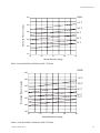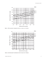
1
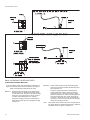
SPLIT-SYSTEM HEAT PUMPS OUTDOOR UNITS INSTALLATION INSTRUCTION 035-16192-001-A-1001 Supersedes: 035-16192-000 (0601) MODELS E1FB180 & E1FB240 O O O O O O O O O O GENERAL The outdoor units are completely piped and wired at the factory and are shipped ready for immediate installation. Only the interconnecting liquid and suction lines, sight glasses, control wiring, and the main power wiring are required to complete the installation. Every unit is dehydrated, evacuated, leak tested and pressure tested at 450 psig before being pressurized with a holding charge of refrigerant-22 for shipment and/or storage. To eliminate the costly cabinet deterioration problems usually associated with outdoor equipment, all sheet metal parts are constructed of commercial grade (G90) galvanized steel. After fabrication, each part is thoroughly cleaned to remove any grease or dirt from its surfaces. The parts that will be exposed to the weather are then coated with a “desert sand” powder paint to assure a quality finish for many years. This coating system has passed the 750-hour, salt spray test per ASTM Standard B117. Every unit includes 2 heavy-duty scroll compressors, 2 suction line accumulators, 2 4-way reversing valves with a 24 volt solenoid, 2 outdoor fan motors with inherent protection, and a copper tube/aluminum fin coil that is positioned vertically for better drainage of the water that will condense on it during the heating cycle. They also include 2 filter driers, 2 expansion valves and distributors that are only used during the heating cycle plus a check valve to provide the proper flow of refrigerant through the unit during both the cooling and heating cycles. All controls are located in the front of the unit and are readily accessible for maintenance, adjustment and service. All wiring (Power and Control) can be made through the front of the unit. REFERENCE This instruction covers the installation and operation of the basic condensing unit. For information on the installation and operation of the matching indoor units, refer to Installation Instruction part no. 035-16626-000 (form 515.41-N4Y). All accessories come with a separate Installation Manual. Refer to Parts Manual for complete listing of replacement parts on this equipment. All forms may be ordered from: Standard Register Norman, OK 73069 Toll Free: Tel. 877-318-9675/Fax. 877-379-7920 INSPECTION As soon as a unit is received, it should be inspected for possible damage during transit. If damage is evident, the extent of the damage should be noted on the carrier's freight bill. A separate request for inspection by the carrier's agent should be made in writing. Installer should pay particular attention to the words: NOTE, CAUTION and WARNING. Notes are intended to clarify or make installation easier. Cautions are given to prevent equipment damage. Warnings are given to alert installer that personal injury and/or equipment damage may result if installation procedure is not handled properly. 035-16192-001-A-1001 TABLE OF CONTENTS GENERAL ............................................................................. REFERENCE ............................................................................. INSPECTION ............................................................................. NOMENCLATURE...................................................................... MAINTENANCE 1 1 1 2 CLEANING ............................................................................. LUBRICATION............................................................................ REPLACEMENT PARTS ............................................................ NOTICE TO OWNER.................................................................. INSTALLATION LIMITATIONS ............................................................................. LOCATION Roof-Top Locations............................................................. Ground Level Locations...................................................... RIGGING AND HANDLING ........................................................ CLEARANCES ........................................................................... COMPRESSOR CRANKCASE HEATER ................................... POWER AND CONTROL WIRING Power Wiring ...................................................................... Control Wiring ..................................................................... REFRIGERANT PIPING General Guidelines ............................................................. Line Sizing .......................................................................... Service Valves .................................................................... Installation........................................................................... EXTENDING THE SERVICE PORTS......................................... EVACUATING AND CHARGING ................................................ BALANCE POINT SETTING....................................................... ALTERNATE CHARGING METHODS........................................ 3 LIST OF FIGURES 3 3 3 4 4 Figure No. 1 2 3 4 5 6 7 8 9 4 4 7 7 7 7 9 9 9 10 Description Page Center of Gravity .................................................. 3 Typical Rigging..................................................... 4 Typical Field Wiring .............................................. 5 Unit Dimensions & Clearances ............................ 6 Extending The Service Ports................................ 10 Refrigerant Flow Diagram .................................... 11 Charging Curves EFB180A.................................. 15 Charging Curves EFB240A.................................. 15 Heating Mode Charging Chart At 4800 CFM ....... 16 EFB180A Heating Mode Charging Chart At 6000 CFM ....... 16 EFB180A Heating Mode Charging Chart At 6600 CFM ....... 17 EFB180A Heating Mode Charging Chart At 6400 CFM ....... 17 EFB240A Heating Mode Charging Chart At 7000 CFM ....... 18 EFB 240A Heating Mode Charging Chart At 7600 CFM ....... 18 EFB 240A 10 11 12 OPERATION 13 GENERAL ............................................................................. SYSTEM SEQUENCE OF OPERATION Cooling Operation............................................................... Heating Operation............................................................... Defrost Cycle ...................................................................... Operation Below 0°F........................................................... Emergency Heat Operation ................................................ 11 14 11 12 12 13 13 LIST OF TABLES Table No. 1 2 3 4 5 6 START-UP CRANKCASE HEATER (10 Ton Unit Only) ................................ PRE-START CHECK .................................................................. INITIAL START-UP ..................................................................... SAFETY FEATURES.................................................................. SECURE OWNER'S APPROVAL ............................................... 14 14 14 14 14 14 14 14 14 Description Page Unit Application Data............................................ 3 Physical Data ....................................................... 4 Electrical Data ...................................................... 5 Suction Lines........................................................ 7 Liquid Lines .......................................................... 8 Refrigerant Line Charge....................................... 8 PRODUCT NOMENCLATURE E 1 F B 1 8 0 A 2 5 PRODUCT CATEGORY VOLTAGE CODE E = Split-System Heat Pump Outdoor Unit 25 = 208/230-3-60 46 = 460-3-60 PRODUCT GENERATION 1 = First Generation FACTORY INSTALLED HEAT PRODUCT IDENTIFIER FB = Outdoor Unit 2 NOMINAL COOLING CAPACITY A = Not Applicable 180 = 15 Ton 240 = 20 Ton Unitary Products Group 035-16192-001-A-1001 INSTALLATION These beams can usually be set directly on the roof. Flashing is not required. LIMITATIONS These units must be installed in accordance with all national and local safety codes. If no local codes apply, installation must conform with the appropriate national codes. See Table 1 for unit application data. Units are designed to meet National Safety Code Standards. If components are to be added to a unit to meet local codes, they are to be installed at the dealer's and/or the customer's expense. TABLE 1 - UNIT APPLICATION DATA APPLICATION LIMITATIONS Voltage Variation (208/230-3-60) - Volts2 Voltage Variation (460-3-60) - Volts 2 MIN MAX 187 253 414 506 Ambient Air on Outdoor Coil (Cooling Cycle) - °F 45 115 Ambient Air on Indoor Coil (Cooling Cycle) - °F 68 86 Ambient Air on Outdoor Coil (Heating Cycle) - °F 01 70 Ambient Air on Indoor Coil (Heating Cycle) - °F 60 80 1 Rated in accordance with ARI Standard 110, utilization range “A”. 2 Below 0 °F, the control circuit will lock out the compressor and allow the electric heat accessory to cycle at its standby capacity. NOTE: On bonded roofs, check for special installation requirements. GROUND LEVEL LOCATIONS The units must be installed on a substantial base that will not settle. Any strain on the refrigerant lines may cause a refrigerant leak. A one-piece concrete slab with footers that extend below the frost line is recommended. The slab should not be tied to the building foundation because noise and vibration will telegraph. A unit can also be supported by concrete piers. These piers should: (1) extend below the frost line, (2) be located under the unit's four corners and (3) be sized to carry the entire unit weight. Refer to Figure 1 and Table 2 for the center of gravity and unit weight. A gravel bed or some other means of handling the condensate that will drop from the underside of the unit coil during the heating and defrost cycles may have to be provided. APPROXIMATE LOCATION Use the following guidelines to select a suitable location for these units. 1. The outdoor units must be installed outside the building. The outdoor fans are the propeller type and are not suitable for use with duct work. BACK CENTER OF GRAVITY (COIL END) B 76 - 7/8 A 39 - 7/8 FRONT 2. The outdoor and indoor units should be installed as close together as possible and with a minimum number of bends in the refrigerant piping. Refer to REFRIGERANT PIPING for additional information. 3. The outdoor unit should not be installed beneath windows or between structures where normal operating sounds may be objectionable. WARNING: The outdoor unit should not be installed in an area where mud and/or ice could cause personal injury. Remember that condensate will drip from the underside of the unit coils during heat and defrost cycles and that this condensate will freeze when the temperature of the outdoor air is below 32°F. 4. All units require certain clearances for proper operation and service. On either rooftop or ground level installations, rubber padding can be applied between the base rails and their supports to lessen any transmission of vibration. ROOF-TOP LOCATIONS Be careful not to damage the roof. Consult the building contractor or architect if the roof is bonded. Choose a location with adequate structural strength to support the unit. The unit must be mounted on solid level supports. The supports can be channel iron beams or wooden beams treated to reduce deterioration. A minimum of two (2) beams are required to support each unit. The beams should: (1) Be positioned perpendicular to the roof joists. (2) Extend beyond the dimensions of the unit to distribute the load on the roof, (3) Be capable of adequately supporting the entire unit weight. Refer to Figure 1 and Table 2 for load distribution and weights. Unitary Products Group Unit 15 Ton 20 Ton Dim. (in.) A B 16 38 16 38 FIG. 1 - CENTER OF GRAVITY CAUTION: Care should be taken to protect the unit from tampering and unauthorized persons from injury. Screws on access panels will prevent casual tampering. Additional safety precautions such as fences around the unit or locking devices on the panels may be advisable. Check local authorities for safety regulations. RIGGING AND HANDLING Exercise care when moving the unit. Do not remove any packaging until the unit is near the place of installation. Rig the unit by attaching chain or cable slings with hooks to the round lifting holes provided in the base rails. CAUTION: Spreaders, longer than the largest dimension across the unit, MUST be used across the top of the unit. See Figure 2. WARNING: BEFORE LIFTING A UNIT, MAKE SURE THAT ITS WEIGHT IS DISTRIBUTED EQUALLY ON THE CABLES SO THAT IT WILL LIFT EVENLY. Units may also be moved or lifted with a fork-lift from the front, rear or the compressor end only through the slotted openings provided in the base rails. 3 035-16192-001-A-1001 CAUTION: LENGTH OF FORKS MUST BE A MINIMUM OF 54" (when lifting from the compressor end of the unit) and a MINIMUM OF 42" (when lifting from the front or rear of the unit). 5 ft. MIN Remove the nesting brackets from the four corners on top of the unit. All screws that are removed to take these brackets off must be replaced on the unit. CLEARANCES O All units require certain minimum clearances for proper operation and service. Refer to Figure 4 for these clearances. O O O O O O O WARNING: Do not permit overhanging structures or shrubs to obstruct air discharge. O O Additional height may be required for snow clearance if winter operation is expected. COMPRESSOR CRANKCASE HEATER The compressor is equipped with a crankcase heater to prevent refrigerant from mixing with crankcase oil during the “OFF” cycle. The heaters will be energized when the compressor is not running providing the unit disconnect switch is closed. TABLE 2 - PHYSICAL DATA DESCRIPTION 1 Compressor Fans EFB240 (2) 7-1/2 (2) 10 Quantity 2 2 Diameter - inches 24 26 Rating - (Qty) Tons Blades/Pitch (°) Nominal CFM Fan Motors 2 UNIT MODEL EFB180 HP RPM Rows Deep X Rows High 3/32 3/36 10862 11395 1 1 1100 1100 2 X 40 2 X 40 Finned Length - inches 130 130 Face Area - square feet 36.11 36.11 Tube(Copper) OD - inches 3/8 3/8 Fins (Aluminum) per inch 18 20 1-0/1-0 1-0/1-0 Holding Charge (Sys 1 / Sys 2)3 Operating Charge (Sys 1 / Sys 2)4 16-8/17-8 19-0/19-0 Shipping 970 1020 Operating 980 1040 1 These compressors are fully hermetic. The ball bearing, 48 frame, single phase condenser fan motor have internal protection and are directly connected to the condenser fins. Motor rotation is counterclockwise when viewing the lead end, which is opposite the shaft end. 3 The amount of charge in the unit as shipped from the factory. 4 Total operating charge for the condensing unit, matching indoor unit, and 25 feet of interconnecting pipe. 2 CAUTION: Do not attempt to start the compressor without at least eight hours of crankcase heat or compressor damage will occur. 4 FIG. 2 - TYPICAL RIGGING If a unit has just been installed or the unit disconnect switch has been open for a long period of time, move the system switch on the room thermostat to the “OFF” position before closing the unit disconnect switch. Eight hours of crankcase heat are required to drive the liquid refrigerant out of the compressor before the compressor can be started. POWER AND CONTROL WIRING Install electrical wiring in accordance with the latest National Electrical Code (NFPA Standard No. 70) and/or local regulations. The unit should be grounded in accordance with these codes. POWER WIRING Check the voltage of the power supply against the data on the unit nameplate. Check the size of the power wire, the disconnect switch and the fuses against the data in Table 3. NOTE: Copper conductors must be installed between the disconnect switch and the unit. Refer to Figure 4 for the location of the power wire access opening through the front of the unit. This opening will require a field-supplied conduit fitting. The field-supplied disconnect switch must be suitable for an outdoor location. Although it should be installed near the unit, do NOT secure it to the unit cabinet. Refer to Figure 3 for typical field wiring. CONTROL WIRING Refer to Figure 4 for the location of the control wire access opening through the front of the unit. Route the necessary low voltage control wires from terminal block TB2 of the unit control box through this access opening to the indoor unit and to the room thermostat. Refer to Figure 3 for typical field wiring. The room thermostat should be mounted about 5 feet above the floor and located where it will be exposed to normal room air circulation. Do not locate it on an outside wall, near a supply air grille, or where it may be affected by sunlight Unitary Products Group 035-16192-001-A-1001 3-PHASE LINE VOLTAGE POWER SUPPLY Refer to electrical data to size the power wiring, disconnect switch and overcurrent protection*. TERMINALS ON: - Supply Air Blower Motor Contactor 10M OR - Terminal Block Electric Heat Control Box USE COPPER CONDUCTORS ONLY TERMINALS ON COMPRESSOR CONTACTORS 1M &3M GROUND SCREW "Heat Pump only" Units GROUND LUG GROUND LUG Units with Electric Heat Accessory TB1 TB2 R R R C C C Y1 O X Y2 G O O Y1 Y1 W1 Y2 1 X G Y2 1 W1 W1 X HR HC TERMINALS ON HEAT PUMP THERMOSTAT Control wiring (24-volt) OUTDOOR UNIT refer to electrical data to determine the proper wire size. INDOOR UNIT 1 WIRE IN ACCORDANCE WITH LOCAL AND NATIONAL ELECTRICAL CODES Only required when an electric heat accessory is used. *All outdoor units and all heat pump only indoor units require dual element, time delay fuses. Circuit breakers can be used in lieu of fuses for indoor units with an electric heat accessory. FIG. 3 - TYPICAL FIELD WIRING TABLE 3 - ELECTRICAL DATA Compressors Model Number Power Supply System 1 RLA LRA Outdoor Fan Motors System 2 RLA LRA Power Supply System 1 Minimum Maximum System 2 Circuit Qty FLA (Each) Qty FLA (Each) Ampacity Fuse 1 Size Minimum Maximum Minimum Wire Size Wire Length Disconnect 2 AWG 4 AWG E1FB180A25 208/230-3-60 32.1 195.0 32.1 195.0 208/230-1-60 1 4.7 1 4.7 81.6 90 2 AWG E1FB180A46 460-3-60 E1FB240A25 208/230-3-60 16.4 95.0 16.4 95.0 460-1-60 1 2.5 1 2.5 41.9 45 42.0 239.0 208/230-1-60 1 4.7 1 4.7 103.9 110 460-3-60 19.2 125.0 19.2 125.0 460-1-60 1 2.5 1 2.5 48.2 50 88 @ 230 V 126 @ 208 V Amps 100 140 @ 230 V 142 6 AWG 224 0 AWG E1FB240A46 3 8 AWG 2 AWG 42.0 239.0 feet 80 @ 208 V 60 104 @ 208 V 115 @ 230 V 165 @ 208 V 150 182 @ 230 V 8 AWG 111 6 AWG 176 60 1 Maximum fuse or maximum circuit breaker (HACR type per NEC). Based on three 75°C insulated copper conductors in conduit and ambient of 30°C. Based on 5% voltage drop, since unit controls are powered off the unit supply. Two minute time delay between system 1 and system 2. 2 3 Unitary Products Group 5 035-16192-001-A-1001 Unit 15 Ton 20 Ton Dim. (in.) A B 16 38 16 38 All dimensions are in inches. They are subject to change without notice. Certified dimensions will be provided upon request. CENTER OF GRAVITY Connection Entry Suction Line Liquid Line Power Wiring Control Wiring A B C D CLEARANCES Overhead (Top)1 Front (Piping and Access Panels) Left Side Right Side Rear Bottom2 Connection Size 15 Ton 20 Ton 1-1/8 ID 1-3/8 ID 5/8 ID 5/8 ID 2-1/8 KO 2-1/8KO 7/8 KO 7/8 KO 1 2 FIG. 4 - UNIT DIMENSIONS AND CLEARANCES 6 120" 30" 24" 24" 24" 0" Units must be installed outdoors. Overhanging structures or shrubs should not obstruct condenser air discharge. Adequate snow clearance must be provided if winter operation is expected. Unitary Products Group 035-16192-001-A-1001 TABLE 4 - SUCTION LINES 1,2 Model Designation 180 240 System 1 System 2 System 1 System 2 Nominal Capacity (Tons) 7-1/2 7-1/2 10 10 Refrigerant Flow Rate3 (Lbs./Min.) 22.5 22.5 30 30 Type L Copper Tubing (Inches O.D.) 1-1/8 1-1/8 1-3/8 1-3/8 Friction Loss4,5 (PSI/100 Ft.) 4.7 4.7 2.8 2.8 1 All horizontal suction lines should be pitched at least 1 inch every 20 feet in the direction of the refrigerant flow to aid the return of oil to the compressor. 2 Every vertical suction riser greater than 25 feet in height should have a “P” trap at the bottom to facilitate the return of oil to the compressor. Use short radius fittings for these traps. 3 Based on Refrigerant-22 at the nominal capacity of the condensing unit, a suction temperature of 40°F and a liquid temperature of 105°F. 4 Although suction lines should be sized for a friction loss equivalent to a 2°F change in saturation temperature (or approximately 3 psi), sizing the lines for the proper return of oil is more important. 5 These friction losses do not include any allowances for valves or fittings. 6 Since the refrigerant gas velocity may be too low to maintain good oil return up a vertical riser, use the next smaller size. The larger size may be used for horizontal runs for a smaller pressure drop. and/or drafts. Circulation of air to the thermostat should not be blocked by curtains, drapes, furniture, partitions, etc. Some installations may require a locking cover to protect the thermostat from tampering and/or damage. Both the manual and the auto changeover thermostats have non-adjustable, voltage-type anticipators for both cooling and heating. REFRIGERANT PIPING GENERAL GUIDELINES Many service problems can be avoided by taking adequate precautions to provide an internally clean and dry system and by using procedures and materials that conform with established standards. Use hard drawn copper tubing where no appreciable amount of bending around pipes or other obstructions is necessary. Use long radius ells wherever possible with one exception small radius ells for the traps in all vapor risers. If soft copper is used, care should be taken to avoid sharp bends which may cause a restriction. Pack fiber glass insulation and a sealing material such as permagum around refrigerant lines where they penetrate a wall to reduce vibration and to retain some flexibility. Support all refrigerant lines at minimum intervals with suitable hangers, brackets or clamps. Braze all copper to copper joints with Sil Fos-5 or equivalent brazing material. Do not use soft solder. Tables 4 and 5 list friction losses for both the suction and liquid lines on the system. Table 6 shows the amount of refrigerant charge required per foot of refrigerant line. When the evaporator coil is below the condensing unit, the suction line must be sized for both pressure drop and for oil return. For certain piping arrangements, different suction line sizes may have to be used. The velocity of the suction gas must always be great enough to carry oil back to the compressor. When the condensing unit is below the evaporator coil, the liquid line must be designed for the pressure drop due to both friction loss and vertical rise. If the total pressure drop exceeds 40 psi, some refrigerant may flash before it reaches the thermal expansion valve. This flashing will not only cause erratic valve operation and poor system performance, but could also damage the expansion valve. SERVICE VALVES These outdoor units have both vapor and liquid line service valves. Both valves are shipped from the factory front-seated and closed with the valve stem in the maximum clockwise position. These service valves are the back-seating type and have a 1/4" male flare access port for evacuating and charging the system. Shrader access valves are provided on the compressor vapor and discharge lines for pressure checking the system. Insulate all vapor lines with a minimum of 1/2" ARMA-FLEX or equal. Liquid lines exposed to direct sunlight and/or high temperatures must also be insulated. All access ports are sealed with a removable cap. Never remove a cap unless the valve is fully back-seated with its valve stem in the maximum counter-clockwise position because the refrigerant charge will be lost. Never solder vapor and liquid lines together. They can be taped together for convenience and support purposes, but they must be completely insulated from each other. INSTALLATION LINE SIZING When sizing refrigerant lines for a split-system air conditioner, check the following: 1. Suction line pressure drop due to friction at full capacity, Since these units are shipped with a holding charge of Refrigerant-22, they can be checked for a refrigerant leak by opening the access port on the liquid line service valve as follows: Open the valve by turning the 1. stem to its maximum counterclockwise position. 2. Liquid line pressure drop due to friction at full capacity, 3. Suction line velocity for oil return at part capacity, and 4. Liquid line pressure drop due to static head. NOTE: Never base refrigerant line sizes on the OD of the suction and liquid connections on the unit. Unitary Products Group Remove the cap from the 2. access port. WARNING: Provisions for recovering refrigerant releases must be available during all phases of installation, leak testing and charging. Do NOT release refrigerant into the atmosphere. 7 035-16192-001-A-1001 TABLE 5 - LIQUID LINES Model Designation 180 240 System 1 System 2 System 1 System 2 Pressure Drop3 Vertical Friction2 Rise (PSI/100 Ft.) (PSI/Ft.) Nominal Capacity (Tons) Refrigerant Flow Rate1 (Lbs./Min.) Type L Copper Tubing (Inches O.D.) 7-1/2 22.5 5/8 3.5 0.5 10 30.0 5/8 5.8 0.5 1 Based on Refrigerant-22 at the nominal capacity of the condensing unit, a liquid temperature of 105°F and a suction temperature of 40°F. 2 These friction losses do not include any allowances for a strainer, filter-drier, solenoid valve, isolation valve or fittings. 3 The total pressure drop of the liquid line for both friction and vertical rise must not exceed 40 PSI. If the pressure drop exceeds 40 PSI, the liquid refrigerant could flash before it reaches the TABLE 6 - REFRIGERANT LINE CHARGE Refrigerant Line2 Liquid Vapor 1 2 Line Size, OD (In.) 5/8 1-1/8 1-3/8 Refrigerant1 Charge (Lb/Ft) 0.113 0.013 Charges are based on 40°F suction temperature and 105°F liquid temperature. Type “L” copper tubing. Use these line charges to adjust the system operating charge when the refrigerant lines are more or less than the 25 feet listed in Table 2. This warning applies to any disc being removed from a service valve, coil connection, etc. Remove the cap from the 1/4" 3. access port on the liquid line stop valve. Connect a supply of dry nitrogen 4. to this access port. Unbraze the copper disc from 5. the liquid connection while maintaining a minimum flow of dry nitrogen through the connection. After the disc has been removed, Turn the stem in (or clockwise) 3. between 1/4 and 1/2 turn to open the access port. Burnish the external surfaces 1. of the liquid connection on the outdoor unit and the end of the field-supplied piping being used for the liquid line. As soon as some internal pressure is relieved, close the access port. DO NOT remove the entire holding charge. NOTE: Clean surfaces are essential for a well brazed connection. NOTE: The copper disc on the liquid connection will prevent any internal pressure from being relieved through the main port of the liquid line stop valve. 2. Carefully clean the internal surfaces of the above. Any particles left on these surfaces may lead to a future system malfunction. If the unit has already lost its holding charge, it should be leak tested and the necessary repairs should be made. If the unit has maintained its holding charge, you can assume that it has no leaks and proceed with the installation. NOTE: Use only copper tubing that has been especially cleaned and dehydrated for refrigerant use. If the tubing has been open for an extended period of time, it should be cleaned before being used. CAUTION: Dry nitrogen should always be supplied through a connection while it is being brazed or unbrazed because the temperature required to make or break a brazed joint is sufficiently high to cause oxidation of the copper unless an inert atmosphere is provided. The flow of nitrogen should be continued until the joint has cooled. The liquid line connections can now be brazed while maintaining a minimum flow of dry nitrogen through the piping. WARNING The dry nitrogen must always be supplied through a pressure regulating valve. Before installing the liquid line between the outdoor and indoor units, remove the copper disc from the liquid connection on the outdoor unit per the following procedure: NOTE: A filter-drier is factory-mounted in the outdoor unit for the heating cycle and in the indoor unit for the cooling cycle. Do NOT install another filter-drier in the field-supplied liquid line because refrigerant will flow in both directions on a heat pump system. Recover the holding charge of the indoor unit and then remove the sealing caps or discs from both its liquid and vapor connections per the following procedure: Make sure the refrigerant 1. in the line has been recovered and that the liquid service valve on the unit is front-seated and closed. The valve stem should be turned to its maximum clockwise position. 1. Make sure the refrigerant in the lines has been recovered, then drill a small hole through both the liquid disc and the vapor disc. If the holding charge has already been lost, the coil should be leak-tested and the necessary repairs should be made. Drill a small hole through the 2. disc before unbrazing it to permit a flow of dry nitrogen through the connection while it is being unbrazed. 2. Move the dry nitrogen supply from the access port on the liquid line service valve of the outdoor unit to the hole through the vapor disc on the indoor unit. WARNING: This hole is also required to prevent the internal pressure from building up as the disc is being unbrazed and from blowing the disc off. 3. Unbraze the coil's liquid line disc while maintaining a flow of dry nitrogen across the connection and through the hole in the liquid line disc. 8 Unitary Products Group 035-16192-001-A-1001 4. After the disc has been removed, burnish the external surfaces and clean the internal surfaces as outlined above. 3. Tighten the screws to secure the service ports for installation. 5. Move the dry nitrogen supply back to the access port on the liquid line service valve. EVACUATING AND CHARGING 6. Braze the liquid line to the liquid connection on the indoor unit while maintaining a minimum flow of dry nitrogen through the liquid line, the indoor coil and the hole in the vapor disc. 7. Unbraze the disc on the vapor connection of the indoor unit while maintaining the flow of dry nitrogen. With the liquid and suction line service valves closed, connect a vacuum pump through a charging manifold to the access ports on both the liquid and suction line service valves. NOTE: The vacuum pump connections should be short and no smaller than 3/8" O.D. 8. After the disc has been removed, burnish the external surfaces and clean the internal surfaces as outlined above. The refrigerant lines and the evaporator coil can now be evacuated to 500 Microns without disturbing the charge in the condenser coil or the compressor. The vapor piping can now be brazed to the vapor connection on the indoor unit while maintaining a minimum flow of dry nitrogen. After proper evacuation and dehydration, charge refrigerant through the access port on the liquid line service valve allowing the vacuum to draw in as much refrigerant as possible. Before brazing the vapor line to the outdoor unit, make sure the refrigerant in the line has been recovered, then remove the copper disc from its vapor connection per the following procedure: CAUTION: Do not charge liquid refrigerant through the compressor suction connection. 1. Make sure that the vapor line service valve on the outdoor unit is front-seated and closed with its valve stem in the maximum clockwise position. 2. Drill a small hole through the disc before unbrazing it to permit a flow of dry nitrogen through the connection while its being unbrazed. 3. Move the dry nitrogen supply to the access port on the vapor line service valve of the outdoor unit. 4. Unbraze the disc on the vapor line connection of the outdoor unit while maintaining a minimum flow of dry nitrogen through the access port of the vapor line service valve and the hole in the vapor disc. CAUTION: Do not attempt to start the compressor without at least 8 hours of crankcase heat or compressor damage will occur. to continue charging refrigerant, open the liquid and the suction line service valves fully. Turn the stem of the liquid service valve clockwise 1/4 turn to open its access port for reading pressure. Start the compressor (after 8 hours of crankcase heat), turn the stem of the suction line service valve clockwise 1/4 turn to open its service port and continue to charge refrigerant gas through this suction access port until you meet the conditions shown on the charging curve, Figures 7 through 15. Open the liquid and vapor line service valves fully to close their access ports after the system has been charged. BALANCE POINT SETTING 5. After the disc has been removed, burnish the external surfaces and clean the internal surfaces of the vapor connection and the vapor piping. The balance point of a heat pump is the lowest temperature at which the refrigeration system can heat the building without any supplemental resistance heat. The vapor line can now be brazed to the vapor connection on the outdoor unit while maintaining the flow of dry nitrogen. The balance point is dependent upon - After the liquid and vapor lines have been installed, the system should be evacuated and charged. 1. The outdoor design temperature, EXTENDING THE SERVICE PORTS (Refer to Fig. 5) 2. The building heat loss at the outdoor design temperature, and 3. The heating capacity of the system at the outdoor design temperature. 1. Loosen the screws that secure the service ports in shipping position. 2. Push the service ports through the corner post. Unitary Products Group 9 035-16192-001-A-1001 SERVICE PORTS IN SHIPPING POSITION COPPER UNIT WALL 2 SCREWS COPPER TUBE CORNER POST UNIT WALL SIDE VIEW SERVICE PORTS IN INSTALLED POSITION LOOSEN SCREWS COPPER 2 SCREWS CORNER SIDE VIEW (AS SHIPPED) POST PUSH SERVICE PORTS THROUGH UNIT WALL TOP VIEW CORNER POST ( TIGHTEN SCREWS SERVICE PORTS EXTENDED ) SIDE VIEW ( SERVICE PORTS EXTENDED ) FIG. 5 - EXTENDING THE SERVICE PORTS ALTERNATE CHARGING METHODS If you are starting a unit when the ambient temperature is higher or lower than those shown in Figures 7 through 15, either of the following methods may be used. Method 2: Install a field supplied moisture indicating sight glass in the liquid line between the filter-drier and the evaporator coil. Using the charging procedure outlined above, charge refrigerant until the moisture indicating sight glass is clear. Add approximately 2 extra pounds of refrigerant to assure a liquid refrigerant seal at the expansion valve under all operating conditions. Block the flow of the condenser air, if necessary, to assure a head pressure of 280 psig during the charging procedure. Method 1: Determine the total weight of the refrigerant for the total system by adding the required charge for the outdoor unit, the indoor unit and the refrigerant lines using information in Tables 2 (Physical Data) and 6 (Refrigerant Line Charge). Using the charging procedures outlined above, weigh the required amount of refrigerant charge into the unit. 10 Note: The installer should return to the job to verify the operating charge when the ambient temperature is within the conditions shown in Figures 7 through 15. Unitary Products Group 035-16192-001-A-1001 INDOOR COIL NON-ADJUSTABLE THERMAL EXPANSION VALVE FOR HEATING (5°F SUPER HEAT) NON-ADJUSTABLE THERMAL EXPANSION VALVE FOR COOLING (10°F SUPER HEAT) OUTDOOR COIL FILTER DRIERS CHECK VALVE BRAZED CONNECTIONS FIELD-INSTALLED LIQUID LINE REVERSING VALVE WITH 24-VOLT SOLENOID FIELD-INSTALLED VAPOR LINE KEY COOLING CYCLE FLOW HEATING CYCLE FLOW SERVICE VALVES WITH COPPER STUB CONNECTIONS COMPRESSOR SUCTION LINE ACCUMULATOR FIG. 6 - REFRIGERANT FLOW DIAGRAM OPERATION GENERAL During the cooling cycle, when the reversing valve solenoids becomes energized, operation will be the same as any conventional air conditioning system. During the heating cycle, when the reversing valve solenoids becomes de-energized, compressor discharge gas will be diverted to the indoor coil and the outdoor coil will become the evaporator. Refer to Figure 6 for illustration showing the flow of refrigerant through a heat pump system. CAUTION: Reversing valves and check valves are precise mechanical devices and will not tolerate any mechanical abuse such as hammering. If a refrigerant system isn't properly cleaned after a compressor burn-out, scale may build up at these devices and prevent them from operating properly. Unitary Products Group SYSTEM SEQUENCE OF OPERATION The following sequences of operation are based on using the manual changeover thermostat. Refer to the respective unit wiring diagram. COOLING OPERATION The following controls will be 1. energized through terminal O on the thermostat to put the system in the cooling mode. • Relays RY3, RY4, RY5, and RY6 If the fan switch on the thermostat 2. is in the “ON” position, indoor section blower motor contactor 10M will be energized through terminal G to provide continuous blower operation. If the switch is in the “AUTO” position, the blower will operate only when the thermostat calls for cooling operation. 3. When TC1 of the thermostat closes on demand for cooling, a circuit is made from the Y terminal on DC1 and DC2 11 035-16192-001-A-1001 through the defrost control boards and safety switches to energize relays RY1 and RY2, which in turn will energize contactors 1M & 3M, starting the compressors. Contactors 2M and 4M are energized through the NO contacts on auxiliary contactors 1M-AUX and 3M-AUX in order to start the outdoor fan motors. 6. If the discharge pressure reaches 398 psig, the HP1 or HP2 control will open and the defrost control board will lock out the compressor. If the discharge temperature reaches 255°F, TH2 or TH4 thermostat will open and the defrost control board will lock out the compressor. If the suction pressure falls to 7 psig, LP1 or LP2 will open and the defrost control board will lock out the compressor. 4. Relays RY1 and RY2 prevent the electric heat accessory referenced as standby electric heat from being utilized whenever the compressor is in operation. This part of the circuit is covered under HEATING OPERATION. 7. If the control that caused the lockout has automatically reset, the unit can be restarted by one of the following: 5. The thermostat will cycle the unit to satisfy the cooling requirements of the conditioned space. 6. After the unit has shutdown from a cooling cycle or a power interruption, the anti-short cycle feature of the defrost control board will not permit the unit to restart for 5 minutes. This feature prevents the unit from short cycling. 7. If the discharge pressure reaches 398 psig, the HP1 or HP2 control will open and the defrost control board will lock out the compressor. If the discharge temperature reaches 255°F, TH2 or TH4 thermostat will open and the defrost control board will lock out the compressor. If the suction pressure falls to 7 psig, LP1 or LP2 will open and the defrost control board will lock out the compressor. 8. If the control that caused the lockout has automatically reset, the unit can be restarted by one of the following: a. Turning the system switch on the thermostat to the “OFF” position and back to the “COOLING” position. b. Increasing the set point on the thermostat above the temperature in the conditioned space and then returning it to its original setting. c. Opening and closing the power supply main disconnect switch. IN ALL THREE RESET METHODS DESCRIBED ABOVE, A FIVE MINUTE TIME DELAY WILL TAKE PLACE AFTER THE RESET BEFORE THE UNIT WILL RESTART. HEATING OPERATION 1. Reversing valve is de-energized and the system will be in the heating mode. 2. If the fan switch on the thermostat is in the “ON” position, indoor section blower motor contactor 10M will be energized through terminal G to provide continuous blower operation. If the switch is in “AUTO” position, the blower will operate only when thermostat calls for heating operation. 3. When TH1 of the thermostat closes for first-stage heat, a circuit is made for the Y terminal on DC1 and DC2 through the defrost control boards and safety switches to energize relays RY1 and RY2, which in turn will energize contactors 1M and 3M, starting the compressors. Contactors 2M and 4M are energized through the NO contacts on auxiliary contactors 1M-AUX and 3M-AUX in order to start the outdoor fan motors. 4. The thermostat will cycle the unit to satisfy the heating requirements of the conditioned space. 5. After the unit has shutdown from a heating cycle or a power interruption, the anti-short cycle feature of the defrost control board will not permit the unit to restart for 5 minutes. This feature prevents the unit from short cycling. 12 a. Turning the system switch on the thermostat to the “OFF” position and back to the “HEATING” position. b. Decreasing the set point on the thermostat below the temperature in the conditioned space and then returning it to its original setting. c. Opening and closing the power supply main disconnect switch. IN ALL THREE RESET METHODS DESCRIBED ABOVE, A FIVE MINUTE TIME DELAY WILL TAKE PLACE AFTER THE RESET BEFORE THE UNIT WILL RESTART. 8. Standby electric heat will be controlled by second stage TH2 of the thermostat and is controlled through low voltage terminal W1. The standby portion of electric heat cannot operate because relays RY1 and RY2 are energized, opening the circuit to W1, whenever the compressor is operating. 9. When second stage heating TH2 is satisfied, the standby heaters will be de-energized. DEFROST CYCLE When condensate freezes on the outdoor coil during heating operation, it must be defrosted before it blocks the flow of air across the coil. 1. A defrost cycle will be initiated by the defrost control board's demand defrost feature which senses both time and outdoor coil temperatures. 2. When the defrost cycle is initiated, the unit operates as follows: a. Relays RY3 and RY5 will be energized causing the reversing valve solenoids to be energized causing the unit to switch to the cooling cycle. b. Contacts in the DC1 and DC2 will open and deenergize contactors 2M and 4M, causing the outdoor fan motors to shut down. c. Standby heat will be energized through contacts in DC1 and DC2. The operation of standby electric heat will prevent cold drafts in the conditioned space. 3. The defrost cycle will be terminated when: a. the liquid temperature exceeds 90°F, or b. 10 minutes have passed since defrost initiation. The 10 minute cycle time (independent of liquid line temperature) is controlled by the defrost control board. 4. At defrost termination, the unit returns to the normal heating operation. Unitary Products Group 035-16192-001-A-1001 OPERATION BELOW 0°F OUTDOOR TEMPERATURE 1. At 0°F outdoor temperature, the low temperature compressor cutoff thermostat TH1 and TH3 contacts 1 and 3 will open, de-energizing contactor 1M and 3M which shuts down the compressor. Contacts 1 and 2 of thermostat TH1 and TH3 are closed when contacts 1 and 3 are open. This feature allows the standby electric heat (if installed) to operate under control of first stage heating TH1 of the room thermostat whenever the compressor is shut-down by the 1TH control. The standby electric heat will continue to be controlled by the second stage TH2 of the room thermostat same as described under Item 8 of HEATING OPERATION. 2. The indoor section blower operation will be controlled by the first stage heating TH1 of the room thermostat if the fan switch is in the “AUTO” position. EMERGENCY HEAT OPERATION When the system switch on the room thermostat is placed in the EMERGENCY HEAT position, operation is as follows: 1. The emergency heat light on the room thermostat will be energized. 2. Compressors will not operate because the Y circuit of the room thermostat cannot be energized. 3. Standby electric heat (if installed) will be controlled by first stage heating TH1 of room thermostat. 4. Indoor section blower will also be controlled by first stage heating TH1 if fan switch is in the “AUTO” position. Unitary Products Group 13 035-16192-001-A-1001 CRANKCASE HEATER START-UP The crankcase heaters must be energized at least 8 hours before starting the compressor. To energize the crankcase heaters, the main disconnect switch must be closed. During this 8 hour period, the system switch on the room thermostat must be “OFF” to prevent the compressor from starting. CAUTION: DO NOT ATTEMPT TO START THE COMPRESSOR WITHOUT AT LEAST 8 HOURS OF CRANKCASE HEAT OR COMPRESSOR DAMAGE WILL OCCUR. Make sure that the bottom of the compressor is warm to the touch to prove crankcase heater operation. PRE-START CHECK Before starting the unit, complete the following check list: 1. Have sufficient clearances been provided? 2. Has all foreign matter been removed from the interior of the unit (tools, construction or shipping materials, etc.)? 3. Have the outdoor fans been rotated manually to check for free rotation? 4. Are all wiring connections tight? 5. Does the available power supply agree with the nameplate data on the unit? 6. Have the fuses, disconnect switch and power wire been sized properly? 7. Are all compressor hold-down nuts properly secured? 8. Are any refrigerant lines touching each other or any sheet metal surface? Rubbing due to vibration could cause a refrigerant leak. 9. Are there any visible signs of a refrigerant leak, such as oil residue? 10. Is any electrical wire laying against a hot refrigerant line? Keep in mind that this unit has a reverse cycle and that different lines will be hot during the “HEAT” and “COOL” cycles. Only two lines will remain cool for all cycles - the line between the compressor and the accumulator and the line between the accumulator and the reversing valve. INITIAL START-UP 1. Supply power to the unit through the disconnect switch prior to starting the compressor. 2. Move the system switch on the room thermostat to the “COOL” position, and lower its set point to energize both the compressor and the reversing valve. Cool air will be supplied to the conditioned space. 3. Check the compressor amperage. It should not exceed the RLA rating printed on the unit data plate or in Table 3 unless the ambient temperature is above 105°F. 4. Move the system switch on the room thermostat to the “HEAT” position, and increase the set point of the room thermostat until heating is required. The compressor will run, but the reversing valve will be de-energized. Warm air will be supplied to the conditioned space. 5. Check the operation of the indoor unit per Form 515.41-N4Y. 6. Check the entire system for refrigerant leaks. 7. Check for any abnormal noises and/or vibrations, and make the necessary adjustments to correct (e.g. fan blade touching shroud, refrigerant lines hitting on sheet metal, etc.) 8. After the unit has been operating for several minutes, shut off the main power supply at the disconnect switch and inspect all factory wiring connections and bolted surfaces for tightness. SAFETY FEATURES 1. All outdoor fan motors have inherent protection with automatic reset. 2. Every compressor is internally protected against excessive current and temperature by a line break motor protector that is mounted inside the compressor housing and is connected between each winding and the common terminal. This motor protector will interrupt power to the compressor if any of the following overload conditions occur: CAUTION: DO NOT ATTEMPT TO START THE COMPRESSOR WITHOUT AT LEAST 8 HOURS OF CRANKCASE HEAT OR COMPRESSOR DAMAGE WILL OCCUR. a. primary single phasing b. locked rotor c. compressor overload d. insufficient motor cooling This type of motor protection works even with the contactor welded closed. 3. Every compressor is protected by crankcase heaters to prevent refrigerant from accumulating in the crankcases of the compressor during an “OFF” cycle. 4. Outdoor fan motors and the secondary of the control transformer are grounded. 5. A fusible plug on the top of the suction line accumulator serves as a high temperature/high pressure relief device. SECURE OWNER'S APPROVAL: When the system is functioning properly, secure the owner's approval. Show him the location of all disconnect switches and the thermostat. Teach him how to start and stop the unit, how to adjust temperature settings within the limitations of the system MAINTENANCE CLEANING REPLACEMENT PARTS Do not allow dirt to accumulate on the outdoor coil. Clean the coil with a brush or vacuum cleaner as often as necessary to assure good system performance and efficient operation. If the coil is extremely dirty, it may be necessary to use an industrial grade detergent and a hose to clean the fin surface. Contact your local UPG Distribution Center for replacement compressors, fan motors, controls, etc. LUBRICATION The outdoor fan motors are equipped with factory lubricated and sealed ball bearings. They do not require any maintenance. 14 NOTICE TO OWNER If a lockout occurs, check the indoor filters and the outdoor coil before calling a serviceman. If the filters are dirty, clean or replace them. If there is an accumulation of snow, leaves or debris blocking the outdoor air coil, remove the blockage. Reset the thermostat and wait 5 minutes. If the unit doesn't start, call a serviceman. Unitary Products Group 035-16192-001-A-1001 ODDB 400 115 °F Discharge Pressure (psig) 350 105 °F 300 95 °F 85 °F 250 75 °F 200 150 50 60 70 80 90 Suction Pressure (psig) FIG.7 - COOLING MODE CHARGING CHART - EFB180A ODDB 450 115 °F Discharge Pressure (psig) 400 105 °F 350 95 °F 300 85 °F 75 °F 250 200 150 50 60 70 80 90 Suction Pressure (psig) FIG. 8 - COOLING MODE CHARGING CHART -EFB240A Unitary Products Group 15 035-16192-001-A-1001 IDDB 400 80 °F 70 °F 60 °F Discharge Pressure (psig) 350 300 250 200 150 100 50 30 40 50 60 70 80 90 Suction Pressure (psig) FIG. 9 - HEATING MODE CHARGING CHART AT 4800 CFM - EFB180A IDDB 400 80 °F 70 °F 60 °F Discharge Pressure (psig) 350 300 250 200 150 100 50 30 40 50 60 70 80 90 Suction Pressure (psig) FIG. 10 - HEATING MODE CHARGING CHART AT 6000 CFM - EFB180A 16 Unitary Products Group 035-16192-001-A-1001 IDDB 400 Discharge Pressure (psig) 350 80 °F 70 °F 60 °F 300 250 200 150 100 50 30 40 50 60 70 80 90 Suction Pressure (psig) FIG. 11 - HEATING MODE CHARGING CHART AT 6600 CFM - EFB180A IDDB 400 80 °F 70 °F 60 °F Discharge Pressure (psig) 350 300 250 200 150 100 50 30 40 50 60 70 80 90 Suction Pressure (psig) FIG. 12 - HEATING MODE CHARGING CHART AT 6400 CFM - EFB240A Unitary Products Group 17 035-16192-001-A-1001 IDDB 350 80 °F 70 °F Discharge Pressure (psig) 300 60 °F 250 200 150 100 50 30 40 50 60 70 80 90 Suction Pressure (psig) FIG. 13 - HEATING MODE CHARGING CHART AT 7000 CFM - EFB240A IDDB 400 Discharge Pressure (psig) 350 80 °F 70 °F 60 °F 300 250 200 150 100 50 30 40 50 60 70 80 90 Suction Pressure (psig) FIG. 14 - HEATING MODE CHARGING CHART AT 7600 CFM - EFB240A 18 Unitary Products Group 035-16192-001-A-1001 NOTES Unitary Products Group 19 Unitary Products Group 5005 York Drive, Norman, Oklahoma 73069 Subject to change without notice. Printed in U.S.A Copyright by York International Corporation 2001. All Rights Reserved. Code: SBY 035-16192-001-A-1001 Supersedes: 035-16192-000 (0601)