1
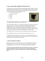
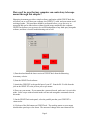
Guide Port Interface Adapter
User’s Manual
Model GPINT-PT
Revision 2.0
Copyright 2004-2005, Shoestring Astronomy
Page 1
Introduction
The Shoestring Astronomy Guide Port Interface Adapter is designed specifically to work
between the parallel port of a desktop or laptop personal computer and the autoguider
port that is a feature on many different telescope mounts. It is a small but important piece
of a total system that allows you to economically autoguide your telescope for long
exposure astrophotography. A typical system includes your scope and mount, a webcam
with scope adapter, this interface adapter, and a personal computer running autoguide
software such as GuideDog from barkoSoftware (www.barkosoftware.com).
Features
•
•
•
•
•
Plugs directly into the computer’s parallel port using a DB-25 male connector.
Connects to the scope mount’s autoguider port using a six-wire RJ12 cable.
Translates signals from pin 6, 7, 8, and 9 (D4, D5, D6, and D7) of the parallel
port to levels that are compatible with the autoguide port.
Provides electrical isolation between the scope mount and the computer. This is
important to avoid noise pickup and ground loops that may be difficult to
troubleshoot.
Passes all parallel port signals through to DB-25 female connector so that other
devices can be controlled with the remaining signals that come out of the parallel
port. An example would be a webcam that has been modified for long exposures.
Page 2
Is my scope mount compatible with this device?
Unfortunately, there is no universally used standard autoguider port interface. However,
many scope mount manufacturers do use a port that has become somewhat of a default
standard. This interface is characterized by a six-pin modular (RJ12) jack that has this
pinout (starting from the left as shown in this picture):
• (1) Open or sometimes powered
• (2) Common (ground)
• (3) RA+
• (4) Dec+
• (5) Dec• (6) RASome manufactures refer to this as ‘ST-4 compatible’, referring to an autoguider that
was made by SBIG (Santa Barbara Instrument Group).
The important thing is that pin 2 is the common, and that the four direction control lines
come out on pins 3, 4, 5, and 6. The Shoestring Astronomy Guide Port Interface
Adapter does not connect anything to pin 1. Most autoguide software, such as
GuideDog, allows the user to configure which pin of the parallel port controls which
direction of movement, so the exact order shown above is not critical. Resistors internal
to the scope mount pull these inputs up to the internal power supply voltage.
Optocouplers, relays, or switches can be used to pull them down to the common pin.
This configuration is sometimes used for simple hand controller ports as well.
Consult the manual that came with your mount to see if the autoguider port or hand
controller port uses this configuration. If this information is not in your manual, contact
the manufacturer’s technical support department.
A note of caution on cables!
Shoestring Astronomy sells cables that are known to be compatible with this adapter.
You can make your own or buy them elsewhere, but be sure that the wires connect
straight through, i.e. pin 1 to pin 1, etc. Some cables change the order of the pins.
If you buy a cable from somewhere other than Shoestring Astronomy, or build your
own, make absolutely sure that it is wired correctly. Incorrect operation and
possibly damage to your mount’s electronics may result if the cable is improperly
wired.
Page 3
How can I be sure that my computer can control my telescope
mount through this adapter?
Shoestring Astronomy provides a simple software application called GPINTCheck that
will allow you to verify that your computer, the GPINT-PT, cable, and your mount are all
working together. This procedure should be performed before you go out to try to
autoguide and can be done indoors without a guide imager attached to the computer.
GPINTCheck allows your system to be verified independent of any third-party autoguide
software, and thus is a useful troubleshooting tool as well.
1) Download and install the latest version of GPINTCheck from the Shoestring
Astronomy website.
2) Start the GPINTCheck software.
3) Attach the GPINT-PT to the parallel port of your PC. Run the RJ-12 cable from the
jack on the GPINT-PT to the jack on your scope mount.
4) Power up your mount. If your mount has a terrestrial mode, make sure it is not in this
mode. Some scopes with terrestrial modes will not take autoguide commands when in
this mode.
5) On the GPINTCheck main panel, select the parallel port that your GPINT-PT is
connected to.
6) Click one of the RA buttons on GPINTCheck. The tracking motor on your mount
should either speed up or slow down. The amount of change in the movement will be
Page 4
very subtle and may not be noticeable by just looking at the mount. Usually the best way
to tell is that you will hear the sound of the tracking motor change.
7) Click the other RA button. Now the mount should behave the opposite of what it did
in step 6.
8) Click the RA buttons so that both are red to end corrections along the RA axis.
9) If you have a declination drive on your mount, click one of the Dec buttons on
GPINTCheck. You should now hear the declination drive motor and possibly see slight
movement of the scope in declination.
10) Click the other Dec button. The declination movement of the mount should reverse.
11) Click the Dec buttons so that both are red to end corrections along the Dec axis.
If you have successfully gone through this procedure, then you know that your parallel
port, the interface adapter, and the scope mount can all communicate. Now you are ready
to try autoguiding using third-party software such as GuideDog!!
How do I hook up the adapter once I am ready to autoguide?
Connecting the Shoestring Astronomy Guide Port Interface Adapter to your computer
and scope mount is quite simple.
1) Plug the male DB-25 connector of the adapter into the parallel port connector on you
computer.
2) Plug an appropriate RJ12 cable (see the note about cables above) into the RJ12 jack
on the adapter.
3) Make sure the autoguider software you are using has properly initialized the parallel
port. Failing to do this may result in your scope slewing uncontrollably and/or
locking up the electronics of your scope mount when you plug the cable into your
mount.
4) Plug the other end of the RJ12 cable into the autoguider or hand controller jack on
your scope mount.
5) If you have a camera or other device that uses parallel port signals for control, plug it
into the female DB-25 connector on the adapter.
Page 5
Limited Warranty
In no event shall Shoestring Astronomy be liable for any claim for incidental or
consequential damage arising out of or in connection, manufacture, delivery or use of
any product offered on this website or by information received by US mail, E-mail,
data files or fax. All products are guaranteed to the original purchaser to be free from
defects in material and workmanship for a period of one year from the date of
purchase. At its option, Shoestring Astronomy will repair or replace the defective
product. Shoestring Astronomy is not responsible for damage caused by the freight
carrier, i.e.: UPS, FED EX, etc., to our product. A claim to repair or replace the
product must be initiated by the recipient. Warranty coverage excludes normal wear
and tear, or damage caused by improper installation, any modification, abuse, misuse,
improper maintenance, and unauthorized repairs or modifications to the original
product. Warranty does not cover those parts prone to failure under normal wear and
tear. Any product repair request must be submitted and approved before shipment to
Shoestring Astronomy. Shipper is responsible for proper packaging, shipping and
insurance on approved repair items. Shoestring Astronomy will package, insure and
return ship at no cost to the customer.
Return Policy
Merchandise may be returned in new (mint) condition within 30 days of receipt for
exchange or a full refund. (less shipping/handling). If you'd like to apply your return
credit to a new order, we'd be happy to do that. Please include this information with
your return. We must receive the returned merchandise within 30 days of the date you
received it. All items must be in new (mint) condition. Returned items cannot show
evidence of use or wear, dirt, or blemishes of any kind. Merchandise must be returned
in its original packaging and should include all supplied materials, instructions,
warranty cards, original accessories, hardware, and any software provided. Shoestring
Astronomy is not responsible for lost or damaged packages. Return shipping costs are
the responsibility of the customer.
Page 6
Guide Port Cabling
Revision 1.0
Copyright 2005, Shoestring Astronomy
Many telescope mounts are capable of autoguiding, or can be modified to add this capability.
Unfortunately, there is no standardized interface that all manufacturers (or even within a single
manufacturer) use for this function. However, most mounts do use a de-facto standard that for lack of a
better name is referred to as ST-4. This refers to a popular model of autoguider from Santa Barbara
Instrument Group (SBIG), the ST-4.
ST-4 interfaces use a modular-style connector and jack similar to telephone cabling, but they are
different. Telephone cabling is referred to as RJ-11 and it uses four wires, and a six position connector
that only has contacts in the middle four positions. ST-4 style guide ports use a modular cable called
RJ-12 that uses six wires, and a six position connector that has contacts in all six positions.
ST-4 style guide ports (sometimes referred to as autoguide ports or CCD ports) look
like the diagram shown to the right. The pins are connected as:
Pin 1:
Pin 2:
Pin 3:
Pin 4:
Pin 5:
Pin 6:
Pin 1
Usually not connected, but this may be power pin on some mounts
Common (ground)
RA+
Dec+
DecRA-
With RJ-12 cables, the six wires are colored white, black, red, green, yellow, and blue. Because the
cable is flat, the modular connector can be crimped onto the cable in two ways, white to pin one or blue
to pin one. Furthermore, when connectors are placed at both ends of a cable, it can be done with pin 1 to
pin 1, or pin 1 to pin 6.
If you build or buy a cable to work with the Shoestring Astronomy guide port
interface products, you must be absolutely sure that is has pin 1 connected to pin
1, pin 2 to pin 2, etc. Otherwise, you risk the possibility of unpredictable
operation and possibly damage to your mount and your Shoestring adapter.
If you build/buy a cable, please make sure that both ends of the cable are wired as
shown in the picture at the right. This view is with the connector lock tab facing away
from you. Note carefully the color and order of the six wires.
Pin 1