1
Operator's
Manual
CRRFrSMRM°
LAWN TRACTO
26.0 HR* 54" Mower
Electric Start
Automatic Transmission
Model No.
917.28008
• EspaSol, p. 37
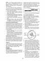
This product has a low emission
engine which operates
differently from previously built engines. Before you start the
engine, read and understand this manual.
IMPORTANT:
Read and follow all Safety
Rules and Instructions before
operating this equipment.
For answers to your questions
about this product, Call:
1-800-659-5917
SEARS Craftsman
5 am - 5 pm, Mon-
Help Line
Sat
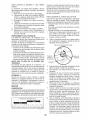
Gasoline containing up to 10% ethanol (EIO) is acceptable for use in this machine.
The use of any gasoline exceeding 10% ethanol (EIO) will void the product warranty.
Esta maquina puede utilizar gasolina con un contenido de hasta el 10% de etanol (EIO).
El uso de una gasolina que supere el 10% de etanol (EIO) anular_ la garantia del producto.
Sears Brands Management
Corporation,
Hoffman
Visit our Craftsman website:www.sears.com/craftsman
448222
Estates,
IL 60179
*As rated
U.S.A.
by the engine
manufacturer
Warranty ..................................................
Safety Rules ............................................
Product Specifications
.............................
Assembly/Pre-Operation
.........................
Operation ...............................................
Maintenance
Schedule ..........................
Craftsman
Riding Equipment
CRAFTSMAN
2
3
6
8
13
21
Maintenance
..........................................
21
Service and Adjustments
.......................
26
Storage ..................................................
31
Troubleshooting
.....................................
32
Sears Service ..........................
Back Cover
Warranty
FULL WARRANTY
FOR TWO YEARS from the date of purchase, all non-expendable parts of this riding equipment are
warranted against any defects in material or workmanship. A defective non-expendable
part will
receive free in-home repair or replacement if repair is impossible.
FOR FIVE YEARS from the date of purchase, the frame and front axle of this riding equipment are
warranted against any defects in material or workmanship. A defective frame or front axle will receive
free in-home repair or replacement if repair is impossible.
FOR 90 DAYS from the date of purchase, the battery (an expendable part) of this riding equipment
is warranted against any defects in material or workmanship (our testing proves that it will not hold a
charge). A defective battery will receive free in-home replacement.
ADDITIONAL
LIFETIME
LIMITED WARRANTY
on CAST IRON FRONT AXLE (if equipped)
FOR AS LONG AS IT IS USED by the original owner after the fifth year from the date of purchase, the
cast iron front axle (if equipped) of this riding equipment is warranted against any defects in material or
workmanship. With proof of purchase, a defective cast front axle will receive free in-home replacement.
WARRANTY
SERVICE
For warranty coverage details to obtain free repair or replacement,
web site: www.craftsman.com
call 1-800-659-5917
or visit the
In all cases above, if part repair or replacement is impossible, the riding equipment will be replaced
free of charge with the same or an equivalent model.
All of the above warranty coverage is void if this riding equipment
commercial services or if rented to another person.
This warranty
include:
covers ONLY defects in material and workmanship.
is ever used while providing
Warranty
coverage
does NOT
• Expendable parts (except battery) that can wear out from normal use within the warranty period,
including but not limited to blades, spark plugs, air cleaners, belts, and oil filters.
• Standard maintenance servicing, oil changes, or tune-ups.
• Tire replacement or repair caused by punctures from outside objects, such as nails, thorns,
stumps, or glass.
• Tire or wheel replacement or repair resulting from normal wear, accident, or improper operation or
maintenance.
• Repairs necessary because of operator abuse, including but not limited to damage caused by
towing objects beyond the capability of the riding equipment, impacting objects that bend the
frame, axle assembly or crankshaft, or over-speeding the engine.
• Repairs necessary because of operator negligence, including but not limited to, electrical and
mechanical damage caused by improper storage, failure to use the proper grade and amount
of engine oil, failure to keep the deck clear of flammable debris, or failure to maintain the riding
equipment according to the instructions contained in the operator's manual.
• Engine (fuel system) cleaning or repairs caused by fuel determined to be contaminated or oxidized
(stale). In general, fuel should be used within 30 days of its purchase date.
• Normal deterioration and wear of the exterior finishes, or product label replacement.
This warranty gives you specific legal rights, and you may also have other rights which vary from
state to state.
Sears Brands
Management
Corporation,
Hoffman
2
Estates,
IL 60179
_DANGER:
This cutting machine is capable of amputating hands and feet and
throwing
objects. Failure to observe the following
safety instructions could result
in serious injury or death.
_,WARNING:
In order to prevent accidental starting when setting up, transporting,
adjusting or making repairs, always disconnect spark plug wire and place wire where
it cannot contact spark plug.
•
_,WARNING:
Do not coast down a hill in
neutral, you may lose control of the tractor.
•
_I, WARNING:
Tow only the attachments
that are recommended by and comply with
specifications of the manufacturer of your
tractor. Use common sense when towing.
Operate only at the lowest possible speed
when on a slope. Too heavy of a load, while
on a slope, is dangerous.
Tires can lose
traction with the ground and cause you to
lose control of your tractor.
•
•
•
_,WARNING:
Engine exhaust, some of
its constituents, and certain vehicle components contain or emit chemicals known to
the State of California to cause cancer and
birth defects or other reproductive harm.
•
•
•
_I_,WARNING: Battery posts, terminals and
related accessories contain lead and lead
compounds, chemicals known to the State of
California to cause cancer and birth defects
or other reproductive harm. Wash hands
after handling.
I. GENERAL
•
•
•
•
•
•
•
•
•
•
OPERATION
Read, understand, and followall instructions on the machine and in the manual
before starting.
Do not put hands or feet near rotating
parts or under the machine. Keep clear
of the discharge opening at all times.
Only allow responsible adults, who are
familiar with the instructions, to operate
the machine.
Clear the area of objects such as rocks,
toys, wire, etc., which could be picked
up and thrown by the blades.
Be sure the area is clear of bystanders
before operating. Stop machine if anyone
enters the area.
Never carry passengers.
Do not mow in reverse unless absolutely
necessary. Always look down and behind
before and while backing.
•
•
3
Never direct discharged materialtoward
anyone. Avoid discharging
material
against a wall or obstruction. Material
may ricochet back toward the operator.
Stop the blades when crossing gravel
surfaces.
Do not operate machine without the entire grass catcher, discharge chute, or
other safety devices in place and working.
Slow down before turning.
Never leave a running machine unattended.
Always turn off blades, set
parking brake, stop engine, and remove
keys before dismounting.
Disengage blades when not mowing.
Shut off engine and wait for all parts to
come to a complete stop before cleaning
the machine, removing the grass catcher,
or unclogging the discharge chute.
Operate machine onlyin daylight orgood
artificial light.
Do not operate the machine while under
the influence of alcohol or drugs.
Watch for traffic when operating near or
crossing roadways.
Use extra care when loading or unloading
the machine into a trailer or truck.
AIways wear eye protection when operating machine.
Data indicates that operators, age 60
years and above, are involved in a large
percentage of riding mower-related injuries. These operators should evaluate
their ability to operate the riding mower
safely enough to protect themselves and
others from serious injury.
Followthemanufacturer'srecommendation for wheel weights or counterweights.
Keep machine free of grass, leaves or
other debris build-up which can touch hot
exhaust / engine parts and burn. Do not
allow the mower to plow leaves or other
debris which can cause build-up to occur. Clean any oil or fuel spillage before
operating or storing the machine. Allow
machine to cool before storage.
li. SLOPE OPERATION
•
Slopes are a major factor related to loss of
control and tip-over
accidents,
which can
result in severe injury or death.
Operation
on all slopes requires extra caution.
If you
cannot back up the slope or if you feel uneasy
on it, do not mow it.
•
Mow up and down slopes, not across.
•
Watch for holes, ruts, bumps, rocks, or
other hidden
objects.
Uneven terrain
could overturn the machine.
Tall grass
can hide obstacles.
•
•
•
Choose a low ground speed so that you
will not have to stop or shift while on the
slope.
Do not mow on wet grass. Tires may lose
traction.
•
•
•
•
•
Before and while backing,
look behind
and down for small children.
•
Nevercarrychildren,
even withthe blades
shut off. They may fall off and be seriously
injured or interfere
with safe machine
operation. Children who have been given
rides in the past may suddenly appear in
the mowing area for another ride and be
run over or backed over by the machine.
Never allow children to operate the machine.
•
Use extra care when approaching
blind
corners, shrubs, trees, or other objects
that may block your view of a child.
IV. TOWING
Avoid starting, stopping, or turning on a
slope. Ifthetires
Iosetraction,
disengage
the blades and proceed slowly straight
down the slope.
Keep all movement
on the slopes slow
and gradual.
Do not make sudden
changes
in speed or direction,
which
could cause the machine to roll over.
•
Use extra care while operating machine
with grass catchers or other attachments;
they can affect the stability
of the machine. Do no use on steep slopes.
Do not try to stabilize the machine
by
putting your foot on the ground.
Do not mow near drop-offs,
ditches,
or embankments.
The machine
could
•
Tow only with a machine that has a hitch
designed for towing. Do not attach towed
equipment
except at the hitch point.
Followthemanufacturer'srecommenda-
•
tion for weight limits for towed equipment
and towing on slopes.
Never allow children or others in or on
•
•
towed equipment.
On slopes, theweight
ofthetowed
equipment may cause loss of traction and loss
of control.
Travel slowly
stop.
and allow extra distance
to
V. SERVICE
SAFE HANDLING
suddenly
roll over if a wheel is over the
edge or if the edge caves in.
OF GASOLINE
To avoid personal
injury or property
damage, use extreme care in handling gasoline.
Gasoline
is extremely
flammable
and the
vapors are explosive.
•
Extinguish
all cigarettes,
cigars, pipes,
and other sources of ignition.
•
Use only approved
gasoline container.
•
Never remove gas cap or add fuel with
the engine running. Allow engine to cool
before refueling.
•
Never fuel the machine indoors.
•
Neverstorethe
machine orfuel container
Iii. CHILDREN
,_WAFINING:
CHILDREN CAN BE INJURED
BY THIS EQUIPMENT, The American
Academy of Pediatrics recommends
that children
be a minimum
of 12 year of age before operating a pedestrian
controlled
lawn mower
and a minimum
of 16 years of age before
operating
a riding lawn mower.
Tragic accidents
can occur if the operator
is not alert to the presence
of children.
Children are often attracted to the machine
and the mowing
activity.
that children
will remain
saw them.
•
•
Always keep the machine in gear when
going down slopes. Do not shift to neutral
and coast downhill.
Keep children
out of the mowing
area
and in the watchful care of a responsible
adult other than the operator.
Be alert and turn machine
off if a child
enters the area.
Never assume
where you last
•
where there is an open flame, spark,
pilot light such as on a water heater
other appliances.
Never fill containers
inside a vehicle
or
or
or
on a truck or trailer bed with plastic liner.
Always place containers
on the ground
away from your vehicle when filling.
4
•
•
•
•
Remove gas-powered
equipment
from
the truck or trailer and refuel it on the
•
ground. Ifthis is not possible, then refuel
such equipment with a portable container,
rather than from a gasoline
dispenser
nozzle.
•
Keep the nozzle in contact with the rim
of the fuel tank or container
opening at
all times until fueling is complete.
Do not
use a nozzle lock-open
device.
Iffuel is spilled on clothing, change clothing immediately.
Never overfill fueltank.
Replace gas cap
and tighten securely.
•
GENERAL
•
•
•
•
•
•
•
•
•
•
SERVlCE
•
Never operate machine in a closed area.
Keep all nuts and boltstight to be sure the
equipment
is in safe working condition.
•
Maintain or replace safety and instruction
labels, as necessary.
Be sure the area is clear of bystanders
before operating.
Stop machine if anyone
enters the area.
Never carry passengers.
Do not mow in reverse unless absolutely
necessary. Always look down and behind
before and while backing.
Never
carry children,
even with the
blades shut off. They may fall off and
be seriously injured or interfere with safe
machine
operation.
Children who have
been given rides in the past may suddenly
appear in the mowing area for another
ride and be run over or backed over by
the machine.
•
Be alert and turn machine
enters the area.
•
Before and while backing,
look behind
and down for small children.
•
Mow up and down slopes (15 ° Max), not
across.
Choose a low ground speed so that you
will not have to stop or shift while on the
slope.
Avoid starting, stopping,
or turning on a
slope. Ifthetires Iosetraction,
disengage
the blades and proceed slowly straight
down the slope.
If machine
stops while going
uphill,
disengage
blades, shift into reverse and
back down slowly.
Do not turn on slopes unless necessary,
and then, turn slowly
and gradually
downhill,
if possible.
When loading orunloadingthis
machine,
do not exceed
the maximum
recom-
•
•
•
•
Keep children out of the mowing area
and in the watchful care of a responsible
adult other than the operator.
Nevertamperwithsafetydevices.
Check
their proper operation
regularly.
Keep machine free of grass, leaves, or
other debris build-up.
Clean oil or fuel
spillage and remove any fuel-soaked
debris. Allow machine to cool before storing.
If you strike a foreign object, stop and
inspectthe
machine. Repair, if necessary,
before restarting.
Never make any adjustments
or repairs
with the engine running.
Checkgrasscatchercomponentsandthe
discharge
chute frequently
and replace
with manufacturer's
recommended
parts,
when necessary.
Mower blades are sharp. Wrap the blade
or wear gloves, and use extra caution
when servicing them.
Check brake operation frequently.
Adjust
and service as required.
•
mended
5
operation
angle
off if a child
of 15 °.
PRODUCT
SPECIFICATIONS
Gasoline Capacity
and type:
3 Gallons/11,35
L
Regular Unleaded
Oil Type:
API: SG-SL)
SAE 10W30 (above32°F/0°C)
SAE 5W30 (below 32°F/0°0)
Oil Capacity:
64 Oz./1,96
Spark
Champion RC12YC
(Gap: .030"/0.76 mm)
Plug:
L
REPAIR PROTECTION
Ground Speed
(Mph/Kph):
Forward:
Reverse:
0 - 5.2/8,4
0 - 2.9/4,7
Charging
15 Amps
@ 3600 RPM
System:
Battery:
Amp/Hr:
Min. CCA:
Case size:
Blade Bolt Torque:
45-55
In the state of California the above is required
by law (Section 4442 of the California
Public
Resources
Code).
Other states may have
similar laws. Federal laws apply on federal
lands.
A spark arrester
for the muffler is
available through your nearest Sears service
center (See REPAIR PARTS manual).
Congratulations
on making
a smart purchase. Your new Craftsman®
product
is
designed
and manufactured
for years of
dependable
operation.
But like all products,
it may require repair from time to time. That's
when having a Repair Protection Agreement
can save you money and aggravation.
28
230
U1R
Ft. Lbs./62-75
Nm
Purchase
a Repair Protection
Agreement
now and protect yourseff from unexpected
hassle and expense.
CONGRATULATIONS
on your purchase of
a new tractor. It has been designed, engineered and manufactured to give you the best
possible dependability
and performance.
Should you experience any problem you cannot easily remedy, please contact a Sears or
other qualified service center. We have competent, well-trained representatives and the
proper tools to service or repair this tractor.
Please read and retain this manual. The
instructions will enable you to assemble
and maintain your tractor properly. Always
observe the "SAFETY RULES".
CUSTOMER
Here's
•
the safety
sections
included
Expert service byour
repair specialists.
Product
product
in the Agreement:
12,000 professional
replacement
can't be fixed.
if your
covered
Discount
of 10% from regular price of
service
and service-related
parts not
covered bythe agreement;
also, 10% off
regular price of preventive
maintenance
check.
Fast help by phone - phone support
from a Sears representative
on products
requiring in-home repair, plus convenient
repair scheduling.
rules.
• Follow a regular schedule in maintaining,
caring for and using your tractor.
• Follow instructions
under "Maintenance"
and "Storage"
what's
Unlimited service and no charge for parts
and labor on all covered repairs.
RESPONSIBILITIES
• Read and observe
AGREEMENTS
Once you purchase the Agreement,
a simple
phone call is all that it takes for you to schedule service. You can call anytime day or night,
or schedule
a service appointment
online.
of this manual.
• Wear proper Personal Protective
Equipment (PPE) while operating this machine,
including (at a minimum)
sturdy footwear,
eye protection,
and hearing
protection.
Do not mow in shorts and/or open toed
footwear.
Sears has over 12,000 professional
repair
specialists,
who have access to over 4.5
million quality parts and accessories.
That's
the kind of professionalism
you can count on
to help prolong the life of your new purchase
for years to come. Purchase
your Repair
Protection Agreement
today!
• Always let someone know you are outside
mowing.
_i, WARNING:
This tractor is equipped with
an internal combustion
engine and should
not be used on or near any unimproved
forest-covered,
brush-covered
or grasscovered
land unless the engine's
exhaust
system is equipped
with a spark arrester
meeting
applicable
local or state laws (if
any).
If a spark arrester is used, it should
be maintained
in effective working order by
the operator.
Some limitations
and exclusions
apply.
For prices and additional
information
call
1-800=827=6655.
SEARS
INSTALLATION
SERVICE
For Sears professional
installation
of home
appliances,
garage
door openers,
water
heaters, and other major home items, in the
U.S.A. call 1-800-4-MY=HOME®
6
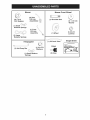
Mower Front Wheel
Mower
(2) Rear
Lift Link
Assernblies
(5)
O.D.1-3/16
Washers
(1) Shoulder Bolt
\_4
©
(1) 1-1/40.D.
Washer
(1) Small
©
Retainer Springs
(1) Front
Lift Link
Assernbly
(1) Wheel
(1) 3/8-16
Locknut
(5) Large
Retainer Springs
if Equipped
(1) Anti=Sway Bar
(1) Oil Drain Tube
©
Keys
(1) 3/40.D.
Washers
(2) Keys
(1) Small Retainer
Springs
7
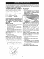
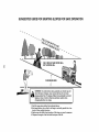
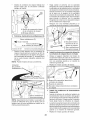
Slope Sheet
Your new tractor has been assembled
at the factory with exception
of those parts left
unassembled
for shipping purposes.
To ensure safe and proper operation of your tractor
all parts and hardware
you assemble
must be tightened
securely.
Use the correct tools
as necessary
to ensure proper tightness.
TOOLS REQUIRED
A socket wrench
easier. Standard
(2) 7/16"
FOR
set will make assembly
wrench sizes are listed.
wrenches
Utility
Tire pressure
(1) 3/4" wrench
Pliers
(1) 9/16"
w/drive
wrench
•
•
•
3.
_L, WARNING:
Before starting,
read, understand
and follow all instructions
in the
Operation
section of this manual.
Be sure
tractor is in a well-ventilated
area. Be sure
the area in front of tractor is clear of other
people
TRACTOR
for charging
position.
instructions).
Adjustments"
section
in
Raise attachment
est position.
2.
Release parking
brake pedal.
3.
Place freewheel
control in disengaged
position to disengage
transmission
(See
"TO TRANSPORT"
in the Operation section of this manual).
4.
Roll tractor
Continue
Label
8
(See
and
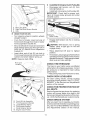
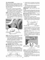
1.
For battery and battery cable installation
see "REPLACING
BATTERY"
in the
"Service
and
this manual.
and objects.
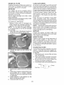
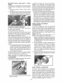
TO ROLL TRACTOR OFF SKID
Operation
section for location
function of controls)
NOTE: If this battery is put into service after
month and year indicated
on label (label is
located between terminals)
charge battery
for minimum of one hour at 6-10 amps. (See
"BATTERY"
in Maintenance
section of this
•
lever (A) and slide seat
position is reached
to press clutch/brake
down.
lock seat in position.
NOTE: You may now roll your tractor off
the skid. Follow the appropriate
instruction
below to remove the tractor from the skid.
BATTERY
Lift hood to raised
manual
Lift up adjustment
until a comfortable
which allows you
pedal all the way
Release lever to
Flashlight
BEFORE
REMOVING
FROM SKID
1.
2.
ratchet
Remove all accessible
loose parts and
parts cartons
from carton.
Cut along dotted lines on all four panels of carton. Remove end panels and
lay side panels flat.
Remove mower and packing materials.
Check for any additional
loose parts or
cartons and remove.
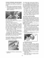
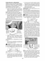
TO CHECK
Sit in seat.
gauge
When right or left hand is mentioned in this
manual, itmeanswhen you are inthe operating
position (seated behind the steering wheel).
TO REMOVE
TRACTOR
FROM
CARTON
UNPACK CARTON
•
1.
knife
(1) 1/2" wrench
(1) 3/4" socket
ADJUST SEAT
ASSEMBLY
lift lever to its highbrake
forward
by depressing
off skid.
with the instructions
that follow.
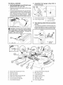
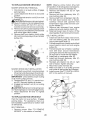
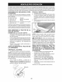
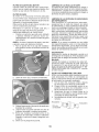
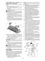
TO INSTALL MOWER
Assemble
front
front of mower.
.
1. Set Parking Brake Lever (P)And Lower
Attachment Lift Lever (N).
• Depress clutch/brake pedal all the way
down and hold.
gauge
wheel
(W) to
Pull parking brake lever (P) up and hold,
release pressure from clutch/brake
pedal,
then release parking brake lever. Pedal
should remain in brake position.
Make
sure parking brake will hold tractor secure.
7
7
H. Front Mower Bracket
X.
Shoulder Bolt
W. Front Gauge Wheel
Y.
Z.
11/40.D. Washer
3/8-16 Locknut
3.
Turn steering
mower.
wheel
left and position
• Turn steering wheel to the left as far as it
will go and position mower on right side of
tractor with deflector shield (Q) to the right.
R Parking Brake Lever
_IkCAUTION:
Lift lever (N) is spring loaded.
Have a tight grip on lift lever, lower it slowly
and engage in lowest position. Lift lever is
located on left side of fender.
Front
Transaxle
Q, Deflector
Shield
N. Lift Lever
Left Side Rear Mower Bracket
K. Belt Tension Rod
A. Mower Side Suspension Arms
B. Retainer Spring
C. Rear Lift Link(s)
D. Right Side Rear Mower Bracket
E. Front Lift Link Assembly
R Front Suspension Bracket
H, Front Mower Bracket
I,
L.
M.
Q.
S.
W.
9
Locking Bracket
Engine Clutch Pulley
Deflector Shield
Anti-Sway
Bar
Front Gauge Wheel
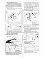
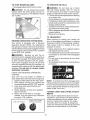
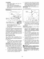
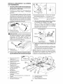
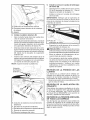
4. Slide mower under tractor.
,
•
Bring belt forward
and check belt for
proper routing in all mower pulley grooves.
NOTE:
Be sure mower
side suspension
arms (A) are pointing forward before sliding
mower under tractor.
•
Slide mower
under tractor
centered
under tractor.
until
it is
•
Pivot the integrated
washer end of antisway bar (S) towards mower deck bracket
on right side of mower. Insert integrated
washer end of bar into hole in rear mower
bracket (D). Move mower as needed to
insert integrated
washer end of bar into
rear mower bracket (D).
Secure
with small washer
and small
retainer spring as shown.
/
--_
y
i
5.
Install
anti-sway
Anti-Sway
D. Right Side Rear
Mower Bracket
S. Anti-Sway Bar
T. Transaxle Bracket
bar (S) Of equipped)
Bar (S)
Towards _
Mower Deck p-
90 ° End
Attach mower
(A) to chassis.
,
Position front hole in side suspension arm
(A) over pin on outside of tractor chassis
and secure with large washer and large
retainer spring (B).
•
Repeat
Integrated Washer End
From right side of mower, first insert
90 ° end of anti-sway
bar (S) into hole in
transaxle
bracket (T), located near left
rear tire in front of transaxle.
NOTE:
6.
Flashlight
side suspension
on opposite
arms
side of tractor.
may be helpful.
Anti-Sway Bar
(S) Location
'_
ii
Transaxle Bracket (T)
Located Between Rear Tires
/
A. Mower Side Suspension Arms
B. Retainer Spring
D. Right Side Rear Mower Bracket
NOTE: Depending on model, bracket (T) may
be different than shown but hole for anti-sway
bar will be in same position/location.
10
7.
Attach
,
Insert rod end of rear lift link (C) into hole
(U) in tractor lift shaft suspension
arm
and pivot link down to mower.
rear lift
links
•
Lift rear corner of mower and position slot
in link assembly over pin on rear mower
bracket (D) and secure with large washer
and large retainer spring.
•
Repeat
on opposite
(C)
side of tractor.
m
\
m
\
\
\
9
install Belt On Engine
•
Disengage
belt tension
locking bracket (L).
•
Install
belt onto engine
Clutch
Pulley (M)
rod
clutch
(K)
pulley
from
(M).
IMPORTANT:
Check belt for proper routing in all mower pulley grooves and under
mandrel covers.
C.
D.
U,
Rear Lift Link(S)
Right Side Rear Mower Bracket
Hole
8
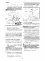
•
Attach front link (E)
Turn steering wheel to position wheels
straight forward.
• From front of tractor, insert rod end of
front link (E) through front hole in tractor
front suspension bracket (F).
• Move to left side of mower and and insert
large retainer spring (G) through hole in
front link (E) behind front suspension
bracket (F).
• Insert other end of link (E) into hole in
front mower bracket (H) and secure with
washer and small retainer spring (J).
NOTE: Requires deck lifting.
Front Link
Location
i-
M.Engine
Clutch Pulley
•
Engage belt tension rod (K) on locking
bracket (L).
CAUTION:
Belt tension rod is spring
loaded. Have a tight grip on rod and
engage slowly.
Raise attachment
position.
lift
lever
to
highest
If necessary, adjust gauge wheels before
operating mower as shown in the owner's/
operator's manual. Check gauge wheels,
deck level and rake settings.
..............
CHECK
/
TIRE PRESSURE
The tires on your tractor were overinflated
at the factory for shipping purposes. Correct
tire pressure
is important for best cutting
performance.
• Reducetire pressureto
PSI shown on tires.
CHECK
DECK LEVELNESS
For best
should be
MOWER"
section of
cutting
results,
mower
housing
properly leveled. See "TO LEVEL
in the Service and Adjustments
this manual.
CHECK FOR PROPER POSITION
ALL BELTS
OF
See the figures that are shown for replacing
motion and mower blade drive belts in the
Service and Adjustments
section of this manual. Verify that the belts are routed correctly.
CHECK
E.
R
G,
H,
J.
M,
Front Lift Link Assembly
Front Suspension Bracket
Large Retainer Spring
Front Mower Bracket
Small Retainer Spring
Engine Clutch Pulley
BRAKE SYSTEM
After you learn how to operate your tractor,
checkto seethat the brake is operating properly. See "TO CHECK BRAKE" in the Service
and Adjustments
section of this manual.
11
_fCHECKLIST
Before you operate your new tractor, we
wish to assure that you receive
the best
performance
and satisfaction
from this
Quality Product.
Please review the following
checklist:
_" All assembly
instructions
have
completed.
_" No remaining
loose
been
parts in carton.
_" Battery is properly
prepared
_" Seat is adjusted
ened securely.
comfortably
and charged.
and tight-
_" All tires are properly inflated. (For shipping purposes, the tires were overinflated
at the factory).
_" Be sure mower deck is properly leveled
side-to-side/front-to-rear
for best cutting
results.
(Tires must be properly inflated
for leveling).
_" Check mower and drive belts.
Be sure
they are routed properly around
and inside all belt keepers.
pulleys
_/" Check wiring.
See that all connections
are still secure and wires are properly
clamped.
_/" Before driving tractor, be sure freewheel
control is in "transmission
engaged" position (see "To Transport"
in the Operation
section of this manual).
While learning
extra attention
items:
_/" Engine
how to use your tractor, pay
to the following
important
oil is at proper
level.
_/" Fuel tank is filled with fresh, clean, regular
unleaded gasoline.
_/" Become familiar
with all controls,
their
location
and function.
Operate
them
before you start the engine.
_/" Be sure brake system is in safe operating
condition.
_/" Be sure Operator
Presence System and
Reverse
Operation
System
(ROS) are
working properly (See the Operation and
Maintenance
sections in this manual).
_/" It is important to purge the transmission
before operating your tractor for the first
time.
Follow proper starting and transmission purging
instructions
(See "TO
START ENGINE" and "PURGE TRANSMISSION"
manual).
in the Operation
section
of this
12
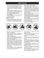
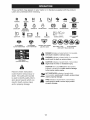
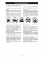
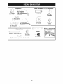
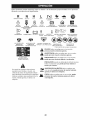
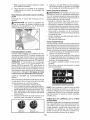
These symbols may appear on your tractor or in literature supplied with the product.
Learn and understand their meaning.
REVERSE
NEUTRAL
HIGH
LOW
CHOKE
FAST
SLOW
IGNITION
Q
ENGINE OFF
e
ENGINE
ON
ON
FUEL
BATTERY
ENGINE
START
;|;
a
LIGHTS
(e)
6
REVERSE
OPERATION
SYSTEM (ROS)
REVERSE
PARKING
t
FORWARD
SWITCH
.¢,
BRAKE
MOWER
HEIGHT
MOWER
LIFT
®$ t- o
CRUISE
CONTROL
CLUTCH/BRAKE
PEDAL
@@®@@
ATTACHMENT
CLUTCH DISENGAGED
ATTACHMENT
CLUTCH ENGAGED
DANGER, KEEP HANDS
AND FEET AWAY
KEEP AREA
CLEAR
(SEE SAFETY
SLOPE
HAZARDS
RULES SECTION)
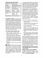
DANGER indicates a hazard which, if not avoided,
will result in death or serious injury.
WARNING indicates a hazard which, if not avoided,
could result in death or serious injury.
FREE WHEEL
(Automatic
Modelsonly)
CAUTION indicates a hazard which, if not avoided,
might result in minor or moderate injury.
CAUTION when used without the alert symbol,
indicates a situation that could result in damage
to the tractor and/or engine.
Failure
to follow instructions
could result in serious injury or
death. The safety alert symbol
is used to identify safety information about hazards which can
result in death,
serious
and/or
damage.
property
injury
,t_llll£1t,,
HOT SURFACES indicates a hazard which,
if not avoided, could result in death, serious injury
and/or property damage.
FIRE indicates a hazard which, if not avoided,
could result in death, serious injury and/or
property damage.
13
KNOW YOUR TRACTOR
READ
THIS
MANUAL
AND
SAFETY
RULES
BEFORE
OPERATING
YOUR
TRACTOR
Compare the illustrations
with your tractor to familiarize
yourself with the locations
various controls and adjustments.
Save this manual for future reference.
Our tractors
conform
American
to the applicable
safety standards
National Standards
Institute.
(A) ATTACHMENT
LIFT LEVER - Used to
raise and lower the mower or other attachments mounted to your tractor.
(B) BRAKE PEDAL - Used for braking
tractor and starting the engine.
(H) LIGHT SWITCH
on and off.
of
of the
- Turns the headlights
(J) CRUISE CONTROL
LEVER - Used to set
forward movement oftractor at desired speed
without holding the forward drive pedal.
the
(C) PARKING
BRAKE - Locks clutch/brake
pedal into the brake position.
(K) FORWARD DRIVE PEDAL
forward movement of tractor.
- Used for
(D) THROTTLE
engine speed.
(L) REVERSE DRIVE PEDALreverse movement of tractor.
Used for
CONTROL-
Used to control
(E) ATTACHMENT
CLUTCH
SWITCH
Used to engage the mower blades, or other
attachments
mounted to your tractor.
(M) FREEWHEEL CONTROL- Disengages
transmission for pushing or slowly towing
the tractor with the engine off.
(F) IGNITION
and stopping
(N) CHOKE CONTROLa cold engine.
SWITCH
- Used for starting
the engine.
Used when starting
(P) SERVICE REMINDER / HOUR METER
- Indicates when service is required for the
engine and mower.
(G) REVERSE
OPERATION
SYSTEM
(ROS) "ON" POSITION
- Allows operation
of mower or other powered attachment
while
in reverse.
14
The operation of any tractor can result in foreign objects thrown into
the eyes, which can result in severe eye damage. Always wear safety
glasses or eye shields while operating your tractor or performing any
adjustments
or repairs. We recommend standard safety glasses or a
wide vision safety mask worn over spectacles.
HOW TO USE YOUR TRACTOR
TO SET
PARKING
NOTE: Failure to move throttle control
between half and full speed (fast) position, before stopping, may cause engine
to "backfire".
BRAKE
Your tractor is equipped with an operator
presence sensing switch. When engine is
running, any attempt bythe operator to leave
the seat without first setting the parking brake
will shut off the engine.
1. Depress brake pedal (B) all the way down
and hold.
2. Pull parking brake lever (C) up and hold,
release pressure from brake pedal (B),
then release parking brake lever. Pedal
should remain in brake position. Make
sure parking brake will hold tractor secure.
• Turn ignition key (F) to "STOP" position
and remove key. Always remove key when
leaving tractor to prevent unauthorized
use.
• Never
use choke
to stop engine.
IMPORTANT:
Leaving the ignition switch in
any position other than "STOP" will cause the
battery to discharge and go dead.
NOTE: Under certain conditions when tractor
is standing idle with the engine running, hot
engine exhaust gases may cause "browning" of grass.
To eliminate
this possibility,
always stop engine when stopping
tractor
on grass areas.
AI_CAUTION:
Always
stop tractor
completely, as described
above, before leaving
the operator's
position.
STOPPING
MOWER
BLADES
-
• To stop mower blades, move attachment
clutch control to disengaged
position (r_'_).
TO USE THROTTLE
CONTROL
(D)
Always operate engine at full speed (fast).
• Operating
engine at less than full speed
(fast) reduces engine's operating efficiency.
• Full speed (fast) offers the best mower
performance.
(1_)
Attachment
Clutch Control
"Engaged ....
GROUND
(£_1) Attachment
Clutch Control
Disengaged"
IMPORTANT:
pedals return
depressed.
Forward
to neutral
and
brake pedal
reverse
position
when
drive
not
-
• Movethrottle
control (D) between
full speed (fast) position.
CONTROL
(N)
Use choke control whenever you are starting
a cold engine. Do not use to start a warm
engine.
• To engage choke control, pull knob out.
Slowly push knob in to disengage.
DRIVE-
• To stop ground drive, depress
all the way down.
ENGINE
TO USE CHOKE
half and
15
TO MOVE FORWARD AND BACKWARD
The cutting height range is approximately
1"
to 4". The heights are measured
from the
ground to the blade tip with the engine not running. These heights are approximate and may
vary depending
upon soil conditions,
height
of grass and types of grass being mowed.
• The average
lawn should be cut to approximately
2-1/2" during the cool season and to over 3" during hot months.
For healthier
and better looking lawns,
mow often and after moderate
growth.
• For best cutting performance,
grass over
6 inches
in height should
be mowed
twice.
Make the first cut relatively
high;
the second to desired height.
The direction
and speed of movement
is
controlled
by the forward and reverse drive
pedals.
1. Start tractor and release parking brake.
2. Slowly depress forward (K) or reverse(L)
drive pedal to begin movement.
Ground
speed increases
the further down the
pedal is depressed.
TO ADJUST
TO USE CRUISE
CONTROL
NOTE: Adjust gauge wheels
a flat level surface.
The cruise
control
should
only be used
while mowing or transporting
on relatively
smooth, straight surfaces. Other conditions
such as trimming at slow speeds may cause
the cruise control to disengage.
Do not use
the cruise control on slopes, rough tertian
or while trimmimg
or turning.
• With forward
drive pedal depressed
to
desired speed,
pull cruise control lever
(J) up and hold while lifting your foot off
the pedal, then release the lever.
To disengage the cruise control, depress the
brake pedal, tap on forward drive pedal or
push the cruise control lever down.
MOWER
CUTTING
The position of the attachment
determines
the cutting height.
with tractor
on
1. Adjust mower to desired cutting height
(See "TO ADJUST
MOWER
CUTTING
HEIGHT"
in this section of manual).
2. With mower in desired height of cut position, gauge wheels should be assembled
so they are slightly offthe ground. Install
gauge wheel in appropriate
hole. Tighten
securely.
3. Repeat for all, installing gauge wheel in
same adjustment
hole.
HEIGHT
lift lever
(A)
TO OPERATE
Put attachment
height slot.
WHEELS
Gauge wheels
are properly adjusted when
they are slightly offthe ground when mower
is at the desired cutting height in operating
position. Gauge wheels then keep the deck
in proper position to help prevent scalping
in most terrain conditions.
The cruise control feature can be used for
forward travel only.
SYSTEM
CHARACTERISTICS
TO ADJUST
GAUGE
lift lever in desired
MOWER
Your tractor is equipped
with an operator
presence sensing switch. Any attempt bythe
operator to leave the seat with the engine
running and the attachment
clutch engaged
will shut off the engine. You must remain
fully and centrally
positioned
in the seat to
prevent the engine from hesitating or cutting
off when operating your equipment on rough,
rolling terrain or hills.
1. Select desired height of cut with attachment lift lever,
cutting
2.
16
Start mower blades
ment clutch control.
by engaging
attach-
TO STOP MOWER
• Disengage
BLADES
attachment
CAUTION:
clutch
Do not operate
TO OPERATE
control.
ON HILLS
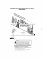
_,WARNiNG:
Do not drive up or down
hills with slopes greater than 15° and do
not drive across any slope. Use the slope
guide provided at the back of this manual.
• Choose the slowest speed before starting
up or down hills.
• Avoid stopping orchanging speed on hills.
• If stopping is absolutely necessary, push
brake pedal quickly to brake position and
engage parking brake.
• To restart movement, slowly release parking brake and brake pedal.
• Slowly depress appropriate drive pedal to
slowest setting.
• Make all turns slowly.
the mower
without either the entire grass catcher, on
mowers so equipped,
or the deflector shield
(S) in place.
TO TRANSPORT
REVERSE
OPERATION
SYSTEM
When pushing
or towing your tractor,
be
sure to disengage
transmission
by placing
freewheel
control in freewheeling
position.
Free wheel control is located
at the rear
drawbar of tractor.
(ROS)
Your tractor
is equipped
with a Reverse
Operation
System (ROS). Any attempt
by
the operator to travel in the reverse direction
with the attachment
clutch engaged will shut
off the engine unless ignition key is placed
in the ROS "ON" position.
,_WARNING"
Backing
up with
the
•
Raise attachment
lift to highest position
with attachment
lift control.
• Pull freewheel
control out and into the slot
and release so it is held in the disengaged
position.
• Do not push or tow tractor at more than
two (2) MPH.
• To reengage transmission,
reverse above
procedure.
at-
tachment
clutch engaged
while mowing is
strongly discouraged.
Turning the ROS "ON",
to allow reverse operation
with the attachment clutch engaged, should only be done
when the operator decides it is necessaryto
reposition
the machine with the attachment
engaged.
Do not mow in reverse
unless
absolutely
necessary.
USING THE
SYSTEM
-
REVERSE
OPERATION
Only use if you are certain no children
or
other bystanders
will enter the mowing area.
1. Depress brake pedal all the way down.
2. With engine running,
turn ignition key
counterclockwise
to ROS "ON" position.
3. Look down and behind before and
4.
5.
while backing.
Slowly depress
start movement.
reverse
drive
co
NOTE: To protect hood from damage when
transporting
you r tractor on a truck or a trailer,
be sure hood is closed and secured to tractor.
Use an appropriate
means
tractor (rope, cord, etc.).
hood to
pedal to
TOWING CARTS AND OTHER ATTACH=
MENTS
Tow only the attachments that are recommended by and comply with specifications
of the manufacturer of your tractor. Use
common sense when towing. Too heavy
of a load, while on a slope, is dangerous.
Tires can lose traction with the ground and
cause you to lose control of your tractor.
When use of the ROS is no longer
needed, turn the ignition key clockwise
to engine "ON" position.
ROS "ON" Position
of tying
Engine "ON" Position
(Normal Operating)
17
SERVICE REMINDER/HOURMETER
Service reminder shows the total number
of hours the engine has run and flashes to
indicatethatthe engineor mowerneedsservicing.When serviceis required,the service
reminderwill flash for two hours. Toservice
engine and mower, see the Maintenance
section of this manual.
NOTE:Servicereminderrunswhenthe ignition key is in any position but "STOP". For
acuratereading, be sure key remains in the
"STOP"positionwhenengineis not running.
BEFORE
CHECK
STARTING
ENGINE
CAUTION:
Alcohol blended fuels (called
gasohol or using ethanol or methanol) can
attract moisture which leads to separation
and formation of acids during storage. Acidic
gas can damagethe fuel system of an engine
while in storage. To avoid engine problems,
the fuel system should be emptied before
storage of 30 days or longer. Drain the gas
tank, start the engine and let it run until the
fuel lines and carburetor are empty. Use
fresh fuel next season. See Storage Instructions for additional information. Never use
engine or carburetor cleaner products in the
fuel tank or permanent damage may occur.
THE ENGINE
OIL LEVEL
TO START ENGINE
When starting the engine for the first time or
if the engine has run out of fuel, it will take
extra cranking time to move fuel from the
tank to the engine.
1. Be sure freewheel control is in the transmission engaged position.
2. Sit on seat in operating position, depress
brake pedal and set parking brake.
3. Move attachment clutch to disengaged
position.
4. Move throttle control to fast position
5. Pull choke control out for a cold engine
start attempt. For a warm engine start
attempt the choke control may not be
needed.
NOTE: Before starting, read the warm and
cold starting procedures below.
6. Insert key into ignition and turn key
clockwise to start position and release
key as soon as engine starts. Do not run
starter continuously for more than fifteen
seconds per minute. If the engine does
not start after several attempts, push
choke control in, wait a few minutes and
try again. If engine still does not start,
pull the choke control out and retry.
The engine in your tractor has been shipped,
from the factory, already filled with summer
weight oil.
1. Check engine oil with tractor on level
ground.
2. Unthread and remove oil fill cap/dipstick;
wipe oil off. Reinsert the dipstick into the
tube and rest oil fill cap on the tube. Do
not thread the cap ontothetube. Remove
and read oil level. If necessary, add oil
until "FULl" mark on dipstick is reached.
Do not overfill.
3. For cold weather operation you should
change oil for easier starting (See the
oil viscosity chart in the Maintenance
section of this manual).
4. To change engine oil, see the Maintenance section in this manual.
5.
Fill fuel tank to bottom
of filler
neck.
Do
not overfill.
Use fresh, clean,
regular
unleaded
gasoline
with a minimum
of
87 octane.
(Use of leaded
gasoline
will increase
carbon
and lead oxide
deposits
and reduce
valve
life). Do
not mix oil with gasoline.
Purchase
fuel in quantities
that can be used
within 30 days to ensure fuel freshness.
WARM WEATH E R STARTI NG (50 °F/10°C
and above)
7. When engine starts, slowly push choke
control in until the engine begins to run
smoothly. If the engine starts to run
roughly, pull the choke control out slightly
for a few seconds and then continue to
push the control in slowly.
8. The attachments and ground drive can
now be used. If the engine does not
accept the load, restart the engine and
allow it to warm up for one minute using
the choke as described above.
_I_CAUTION:
Wipe off any spilled oil or
fuel. Do not store, spill or use gasoline near
an open flame.
IMPORTANT:
When operating
in temperatures below 32°F (0°C), use fresh, clean
winter grade gasoline to help ensure good
cold weather starting.
18
COLD WEATHER
and below)
7.
STARTING
(50°F/10°C
2.
When engine starts, slowly push choke
control in until the engine begins to run
smoothly.
Continue
to push the choke
control in small steps allowing the engine
to accept small changes
in speed and
load, until the choke control is fully in.
If the engine starts to run roughly, pull
the choke control out slightly for a few
seconds and then continue to push the
control
in slowly. This may require an
engine
warm-up
period from several
seconds to several minutes, depending
on the temperature.
AUTOMATIC
TRANSMISSION
WARM
3.
CAUTION:
3.
4.
UP
5.
6.
Be sure the tractor is on level ground.
Release the parking brake and let the
brake slowly return to operating position.
Allow one minute for transmission
to
7.
warm up. This can be done during the
engine warm up period.
4. The attachments
can be used during the
engine warm-up period after the transmission has been warmed up and may require
the choke control be pulled out slightly.
NOTE:
If at a high altitude
(above 3000
feet) or in cold temperatures
(below 32°F)
the carburetor
fuel mixture may need to be
adjusted for best engine performance
(see
"TO ADd UST CARBURETOR"
in the Service
and Adjustments
PURGE
section
8.
TRANSMISSION
To ensure proper operation and performance,
it is recommended
that the transmission
be
purged before operating tractor for the first
time. This procedure will remove any trapped
air inside the transmission
which may have
developed
during shipping of your tractor.
IMPORTANT:
Should
your transmission
require removal for service or replacement,
it should be purged after reinstallation
before
operating the tractor.
Place tractor safely on a level surface that is clear of objects and open - with
engine off and parking brake set.
19
step 4,
of the drive wheels.
manual).
Sitting in the tractor
seat, start engine.
After the engine is running, move throttle
control to half (1/2) speed. Disengage
parking brake.
Drive tractor forward for approximately
five feet then backwards
for five feet.
this
Your transmission
ready for normal
of this manual).
during
Depress forward drive pedal to full forward position and hold forfive (5) seconds
and release pedal. Depress reverse drive
pedal to full reverse
position and hold
for five (5) seconds and release pedal.
Repeat this procedure
three (3) times.
Shutoff engine and set parking brake.
Engage
transmission
by placing freewheel control in engaged
position (See
"TO TRANSPORT"
in this section
of
Repeat
times.
_CAUTION:
Never engage or disengage
freewheel lever while the engine is running.
1.
At any time,
there may be movement
Before driving the unit in cold weather, the
transmission
should be warmed
up as follows:
1.
2.
Disengage
transmission
by placing
freewheel
control in disengaged
position
(See "TO TRANSPORT"
in this section
of manual).
Sitting in the tractor seat, start engine.
After the engine is running, move throttle
control to slow position. Disengage
parking brake.
driving
procedure
is now purged
operation.
three
and now
MOWING
• Tire
TIPS
chains
cannot
be used
when
the
mower housing is attached to tractor.
• Mower should be properly leveled for best
mowing performance.
See "TO LEVEL
MOWER
HOUSING"
in the Service and
Adjustments
section of this manual.
• The left hand side of mower should
be
used for trimming.
• Drive sothat clippings are discharged
onto
the area that has already been cut. Have
the cut area to the right of the tractor. This
will result in a more even distribution
of
clippings and more uniform cutting.
• When mowing large areas, start byturning
to the right so that clippings will discharge
away from shrubs,
fences,
driveways,
etc. After one or two rounds, mow in the
opposite direction making left hand turns
until finished.
j
J
• If grass is extremely
tall, it should
be
mowed twice to reduce load and possible
fire hazard from dried clippings.
Make
first cut relatively high; the second to the
desired height.
• Do not mow grass when it is wet. Wet
grass will plug mower and leave undesirable clumps.
Allow grass to dry before
mowing.
• Always operate
engine
at full throttle
when
mowing
to assure
better mowing performance
and proper discharge
of material.
Regulate
ground speed by
selecting a low enough speed to give the
mower cutting performance
as well as the
quality of cut desired.
• When operating
attachments,
select a
ground speed that will suit the terrain and
give best performance
of the attachment
being used.
20
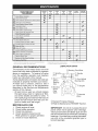
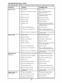
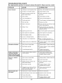
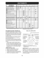
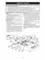
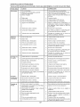
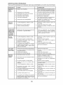
MAINTENANCE
SCHEDULE
Check
Brake
Check
Tire
EACH
USE
Operation
Operator
A
Check
for Loose
C
Check/Replace
EVERY
EVERY
EVERY
EVERY
EVERY
BEFORE
8
HOURS
25
HOURS
50
HOURS
100
HOURS
SEASON
STORAGE
_
Pressure
aT Check
_
Presence
& ROS Systems
Fasteners
Mower
V #
Blades
T
Lubrication
0
Check
R
Clean Battery and Terminals
m
BEFORE
Chart
Battery
Level
Clean
Debris
Check
Transaxle
Check
Mower
Check
V-Belts
Check
Engine
Off Steering
Plate
Cooling
Levelness
v'
Oil Level
_12
Change Engine Oil (with oil filter)
Change
Engine
Oil (without
NE Clean
Air Filter
G
Air Screen
Clean
_1,2
oil filter)
I
Inspect Muffler/Spark
N
Replace Oil Filter (if equipped)
E
Clean Engine Cooling Fins
V'
Arrester
Replace Spark Plug
Replace
B
Air Filter Paper Cartridge
______
RRRRRRRRR_Iace
Fuel Filter
1 - Change
more
often
2 - Service
more
often
when
when
GENERAL
operating
operating
under
in dirty
a heavy
or
dusty
load
or
in high
ambient
temperatures.
conditions.
3 - Replace
4 - Not
when
with
mowing
maintenance-free
in sandy
soil
5 - See
Cleaning
(_S
Zerk
C
Wheel
Bearing
Zerk
in Maintenance
Section.
battery.
CHART
(_Steering
Pivot Bolts
Spindle
Zerk
Front Wheel
Bearing Zerk
Engine
(_ Steering
Sector
Gear
Teeth
• At least once a year you should replace
the spark plug, clean or replace air filter,
and check blades and belts for wear. A
Mandrel
Zerks
new spark plug and clean air filter assure
proper air-fuel mixture and help your engine run better and last longer.
5.
often
LUBRICATION
Some adjustments
will need to be made periodically to properly maintain your tractor.
At least once a season,
check to see if
you should make any of the adjustments
described
in the Service and Adjustments
section of this manual.
1.
2.
3.
4.
more
if equipped
RECOMMENDATIONS
The warranty on this tractor does not cover
items that have been subjected to operator
abuse or negligence.
To receive full value
from the warranty,
operator must maintain
tractor as instructed
in this manual.
BEFORE
blades
required
(_)General
Purpose Grease
(_Refer to Maintenance
"ENGINE"
EACH USE
Check engine oil level.
Check brake operation.
Check tire pressure.
Check operator presence
and
ROS systems for proper operation.
Check for loose fasteners.
Section.
IMPORTANT: Do not oil or grease the pivot
points which have special nylon bearings.
Viscous lubricants will attract dust and dirt
that will shorten the life of the self-lubricating
bearings. If you feel they must be lubricated,
use only a dry, powdered graphite type lubricant sparingly.
21
TRACTOR
Always
forming
BRAKE
observe safety rules when
any maintenance.
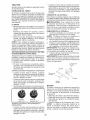
OPERATION
CHECK REVERSE
SYSTEM
per-
• Maintain proper air pressure
in all tires
(See PSI on tires).
• Keep tires free of gasoline,
oil, or insect
control chemicals
which can harm rubber.
For best results
SYSTEM
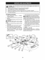
BLADE
1.
(ROS)
be
REMOVAL
Raise mower to highest
access to blades.
position
to allow
Install newbladewith
stamped"THISSIDE
UP" facing deck and mandrel assembly.
iMPORTANT:
To ensure proper assembly,
center hole in blade must align with star on
mandrel assembly.
4. Install and tighten
blade bolt securely
(45-55 Ft. Lbs. torque).
IMPORTANT:
Special
blade bolt is heat
PRESENCE
• When the engine is running, any attempt by the operator to leave the seat
without first setting the parking brake
should shut off the engine.
• When the engine is running and the
attachment
clutch is engaged, any attempt by the operator to leave the seat
should shut off the engine.
• The attachment
clutch should never operate unless the operator is in the seat.
ROS "ON" Position
must
3.
position.
CHECK OPERATOR
SYSTEM
blades
NOTE: Protect your hands with gloves and/
or wrap blade with heavy cloth.
2. Remove blade bolt by turning counterclockwise.
Be sure operator presence
and reverse
operation
systems are working properly,
if
your tractor does not function as described, repair the problem immediately.
• The engine should not start unless the
brake pedal is fully depressed,
and
the attachment
clutch control is in the
disengaged
mower
sharp.
Replace worn, bent or damaged
blades.
_i, CAUTION:
Use only a replacement
blade approved
by the manufacturer
of
your tractor. Using a blade not approved
by the manufacturer
of your tractor is
hazardous,
could damage your tractor and
void your warranty.
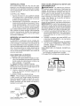
• Avoid stumps, stones, deep ruts, sharp
objects and other hazards that may
cause tire damage.
NOTE: To seal tire punctures
and prevent
flat tires due to slow leaks, tire sealant
may be purchased
from your local parts
dealer. Tire sealant also prevents tire dry
rot and corrosion.
OPERATOR
PRESENCE
SYSTEM AND
OPERATION
(ROS)
• When the engine is running with the
ignition switch in the engine "ON" position and the attachment
clutch engaged,
any attempt by the operator to shift into
reverse should shut off the engine.
• When the engine is running with the
ignition switch in the ROS "ON" position
and the attachment
clutch engaged,
any attempt by the operator to shift into
reverse should NOT shut off the engine.
BLADE CARE
If tractor requires more than five (5) feet to
stop at highest speed in highest gear on a
level, dry concrete or paved surface, then
brake must be serviced.
(See "TO CHECK
BRAKE" in the Service and Adjustments
section of this manual).
TIRES
REVERSE
OPERATION
treated.
Mandrel
Y
Blade
Blade Bolt
Center Hole
BATTERY
Engine "ON" Position
(Normal Operating)
Your tractor has a battery charging system
which is sufficient for normal use. However,
periodic charging of the battery with an automotive charger will extend its life.
• Keep battery
and terminals
• Keep battery
bolts tight.
• Keep small
•
22
Recharge
vent holes
at
clean.
open.
6-10 amperes
for 1 hour.
NOTE: The original
equipment
battery on
your tractor is maintenance
free. Do not
attempt to open or remove caps or covers.
Adding
or checking
level of electrolyte
is
not necessary.
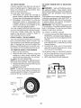
Change the oil after every 50 hours of operation or at least once a year if the tractor
is not used for 50 hours in one year.
Check the crankcase
oil level before starting the engine and after each eight
hours of operation.
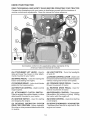
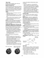
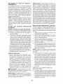
TO CLEAN BATTERY AND TERMINALS
SAE VISCOSITY
Corrosion
and dirt on the battery and terminals can cause the battery to "leak" power.
1. Remove terminal guard.
2. Disconnect
BLACK
battery cable first
then RED battery
cable and remove
battery from tractor.
3. Rinse the battery with plain water and dry.
4. Clean terminals
and battery cable ends
with wire brush until bright.
5. Coat terminals with grease or petroleum
jelly.
6. Reinstall
battery
(See "REPLACING
BATTERY"
in the SERVICE
AND ADJUSTMENTS
TRANSAXLE
section
F:
C
-20
i
-30
0
-2_0
TEMPERATURE
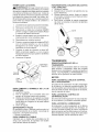
TO CHANGE
60
1_0
RANGE ANTICIPATED
80
i
20
100
i
30
i
40
BEFORE NEXT OIL CHANGE
ENGINE
t4
e
OIL
• Oil will drain more freely when warm.
• Catch oil in a suitable container.
1.
The transmission
fan and cooling fins should
be kept clean to assure proper cooling. Do
not attempt to clean fan or transmission
while
engine is running or while the transmission
is hot. To prevent possible damage to seals,
do not use high pressure water or steam to
clean transaxle.
2.
3.
Remove oil fill cap/dipstick.
Be careful
not to allow dirt to enter the engine
when changing oil.
Remove yellow cap from end of drain
valve and install the drain tube onto
the fitting.
Unlock drain valve
slightly and turning
by pushing inward
counterclockwise.
Oil Drain Valve
• Inspect cooling fan to be sure fan blades
are intact and clean.
• Inspectcoolingfinsfordirt,
grass clippings
and other materials. To prevent damage to
seals, do not use compressed
air or high
pressure sprayer to clean cooling fins.
TRANSAXLE
PUMP FLUID
_pCnloo_si_n
The transaxle was sealed at the factory and
fluid maintenance
is not required for the life
of the transaxle.
Should the transaxle ever
Yellow
leak or require servicing,
contact your nearest Sears or other qualified service center.
4.
5.
V-BELTS
and wear after
100 hours of operation and replace if necessary. The belts are not adjustable.
Replace
belts if they begin to slip from wear.
6.
7.
ENGINE
LUBRICATION
Only use high quality detergent oil rated with
API service classification
SG-SL
Select the
grade according
temperature.
40
0
Determine
temperature
range expected
before oil change.
All oil must meet API
service classification
SG-SL.
• Be sure tractor is on level surface.
MAINTENANCE
oil's SAE viscosity
expected operating
32
GRADES
oi|viscchar
of this manual).
Check V-belts for deterioration
30
i
-10
(8)
8.
to your
23
_
_!_
Drain
_-Tube
To open, pull out on the drain valve.
After oil has drained completely,
close
and lock the drain valve by pushing
inward and turning clockwise
until the
pin is in the locked position as shown.
Remove the drain tube and replace the
cap onto the end of the drain valve.
Refill engine with oil through oil fill dipstick tube. Pour slowly.
Do not overfill.
For approximate
capacity
see "PRODUCT SPECIFICATIONS"
section of this
manual.
Use gauge on oil fill cap/dipstick
for
checking level. Insert dipstick into
the tube and rest the oil fill cap on the
tube.
Do not thread the cap onto the
tube when taking reading.
Keep oil
at "FULl" line on dipstick.
Tighten cap
onto the tube securely when finished.
ENGINEOiL FILTER
Replacethe engineoilfilter everyseason or
every other oil change if the tractor is used
more than 100 hours in one year.
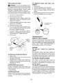
AIR FILTER
Your engine will not run properly using a
dirty air filter. Service paper cartridge every
two months or every 25 hours of operation,
whicheveroccurs first.
Service paper cartridge more often under
dusty conditions.
Replacethe papercartridgeannually,or after
every 100 hours of operation.
TO SERVICE
CARTRIDGE
• Replace
a dirty, bent, or damaged
cartridge. Handle new cartridge carefully; do
not use if the rubber seal is damaged.
NOTE:
Do not wash the paper cartridge
or use pressurized
air, as this will damage
the cartridge.
1. Open door (A) on the blower housing to
access the air cleaner element (B).
CLEAN
AIR SCREEN
Air screen must be kept free of dirt and chaff
to prevent engine damage from overheating.
Clean with a wire brush or compressed
airto
remove dirt and stubborn
dried gum fibers.
CLEAN
AIR INTAKE/COOLING
AREAS
To ensure
proper cooling,
make sure the
grass screen, cooling fins, and other external surfaces
of the engine are kept clean
at all times,
Every 100 hours of operation
(more often
under
extremely
dusty, dirty conditions),
remove the blower housing and other cooling
shrouds. Clean the cooling fins and external
surfaces as necessary. Make surethe cooling
shrouds are reinstalled.
NOTE:
Operating the engine with a blocked
grass screen, dirty or plugged cooling fins,
and/or cooling shrouds removed will cause
engine damage due to overheating.
MUFFLER
Inspect and replace corroded
muffler and
spark arrester (if equipped)
as it could create
a fire hazard and/or damage.
SPARK
PLUG(S)
Replace spark plug(s) at the beginning
of
each mowing
season
or after every
100
hours of operation,
whichever
occurs first.
Spark plug type and gap setting are shown
in "PRODUCT
SPECIFICATIONS"
section
of this manual.
IN=LINE
.
Unhook
element.
the
latch
(C) and
remove
FUEL
The fuel filter should be replaced once each
season.
If fuel filter becomes clogged, obstructing fuel flowto carburetor, replacement
is required.
1. With engine cool, remove filter and plug
fuel line sections.
the
2.
3.
Place newfuel filter in position in fuel line
with arrow pointing towards carburetor.
Be sure there are no fuel line leaks and
4.
clamps are properly positioned.
Immediatelywipeupanyspilled
gasoline.
Clam
Fuel Filter
3.
Gently tap the paper element
dirt.
4.
Clean all air cleaner components
of any
accumulated
dirt or foreign
material.
Prevent any dirt from entering the throat
of carburetor.
Install cleaned or new element
on the
base and secure with latch.
Close and latch the door.
5.
6.
FILTER
to dislodge
24
CLEANING
•
4.
lock the adapter on the nozzle.
IMPORTANT:
Tug hose ensuring
connection is secure.
5.
A CAUTION: Avoid all pinch points and
movable parts
Clutch/brake
of the nozzle
adapter and push the adapter onto the
deck washout port at the left end of the
mower deck. Release the lock collar to
Clean engine, battery, seat, finish, etc.
of all foreign matter.
Clean debris from steering plate.
Debris can restrict clutch/brake
pedal
shaft movement,
causing belt slip and
loss of drive.
•
Pull back the lock collar
Turn the water on.
Nozzle
Ada
pedal
Washout Port
Clean
top
Plate
Steering System, Dash,
Fender and Mower Not Shown
•
•
[oAoTo°
i
_
Pinch
Points
6.
Keep finished surfaces and wheels
free of all gasoline, oil, etc.
Protect painted surfaces with automotive type wax.
iMPORTANT:
Recheck
certain the area is clear.
.
We do not recommend
using a garden hose
or pressure
washer
to clean your tractor
unless
the engine
and transmission
are
covered to keep water out. Water in engine
or transmission
will shorten the useful life of
Move
the
tractor's
the
area
making
attachment
clutch
control to the "ENGAGED"
position.
Remain
in the operator's
position
with the cutting deck engaged until the
deck is cleaned.
your tractor.
Use compressed
air or a leaf
blower to remove grass, leaves and trash
from tractor and mower.
DECK WASHOUT
While sitting in the operator's
position
on the tractor, re-start the engine and
place the throttle lever in the Fast ",_"
position.
.
Move
the
tractor's
attachment
clutch
control to the "DISENGAGED"
position. Turn the ignition key to the STOP
position to turn the tractor's engine off.
Turn the water off.
PORT
Your tractor's
deck
is equipped
with a
washout
port on its surface as part of its
deck wash system. It should be utilized after each use.
1.
Drive the tractor to a level, clear spot
on your lawn, near enough to a water
spigot for your garden hose to reach.
iMPORTANT:
Make certain
the tractor's
9.
Pull back the lock collar of the nozzle
adapter to disconnect
the adapter from
the nozzle washout port.
10.
Move the tractor to a dry area, preferably a concrete
or paved area. Place
the attachment
clutch control
in the
"ENGAGED"
position to remove excess
water and to help dry before putting the
tractor away.
discharge chute is directed AWAY from your
house, garage, parked cars, etc. Remove
bagger chute or mulch cover if attached.
2.
Make sure the attachment
clutch control
is in the "DISENGAGED"
position, set
the parking brake, and stop the engine.
_WARNING:
A broken or missing washout
fitting could expose you or others to thrown
objects from contact with the blade.
• Replace broken or missing washout fitting
immediately, prior to using mower again.
3.
•
Thread the nozzle adapter (packaged
with your tractor's
Operator's
Manual)
onto the end of your garden hose.
25
Plug any holes
Iocknuts.
in mower with bolts
and
&
WARNING: TO AVOID SERIOUS
ADJUSTMENTS:
iNJURY, BEFORE PERFORMING
ANY SERVICE OR
1. Depress clutch/brake
pedal fully and set parking brake.
3. Place attachment
clutch in "DISENGAGED"
position.
4. Turn ignition key to "STOP" and remove key.
5. Make sure the blades and all moving parts have completely
stopped.
6. Disconnect
spark plug wire from spark plug and place wire where it cannot
in contact with plug.
TO REMOVE
MOWER
7.
1.
Place attachment
clutch
in "DISENGAGED" position.
2. Lower attachment
lift lever to its lowest
position.
3. Disengage
belt tension rod (K) from lock
bracket (L).
CAUTION:
Belt tension
rod is spring
loaded. Have a tight grip on rod and release
slowly.
4. Remove mower belt from electric clutch
5.
6.
come
Go to other side of mower and disconnect
_the
suspension
arm and rear lift link.
CAUTION:
After rear lift links are disconnected, the attachment
lift lever will be spring
loaded. Have a tight grip on lift lever when
changing
position of the lever.
8. From right side of mower, disconnect
anti-sway
bar (S) from right rear mower
bracket (D) - remove retainer spring and
washer and pull mower toward you until
the bar falls from the hole in bracket.
9. Turn tractor steering wheel to the left as
far as it will go.
10. Slide mower out from under right side of
tractor.
TO INSTALL
MOWER
pulley (M),
Disconnect
front link (E) from mower remove retainer spring and washer,
Go to either side of mower and disconnect mower suspension
arm (A) from
chassis
and rear lift link (C) from rear
mower bracket
(D) - remove
retainer
springs and washers.
Follow procedure
described
in "INSTALL
MOWER AN D DRIVE BELT" in the Assembly
section of this manual.
26
TO LEVEL
MOWER
4.
Make sure tires are properly inflated to the
PSI shown on tires. Iftires are over or under
inflated, it may affect the appearance
of your
lawn and lead you to think the mower is not
adjusted properly.
VISUAL
SIDE-TO-SIDE
If adjustment
is necessary,
and 3 in Visual Adjustment
above.
5.
Recheck measurements,
adjust if necessary until both sides are equal.
FRONT-TO-BACK
ADJUSTMENT
IMPORTANT:
Deck must be level sideto-side.
ADJUSTMENT
1. With all tires properly inflated and if your
lawn appears
unevenly
cut, determine
which side of mower is cutting lower.
NOTE: As desired,
you can raise the low
side of mower or lower the high side.
2. Go to side of mower you wish to adjust.
3. With a 3/4" or adjustable
wrench, turn
lift link adjustment
nut (A) to the left to
lower the mower, or, to the right to raise
the mower.
To obtain the best cutting results, the mower
blades should be adjusted so the front tip is
1/8" to 1/2" lower than the rear tip when the
mower is in its highest position.
_IL CAUTION:
Blades are sharp. Protect
your hands with gloves and/or wrap blade
with heavy cloth.
• Raise mower to highest position.
• Position any blade so the tip is pointing
straight forward. Measure distance (B) to
the ground at front and rear tip of the blade.
B
Turn nut rig
to raise mower
'.." Turn nut left
to lower mower
SIDE-TO-SIDE
B
• If front tip of blade is not 1/8" to 1/2" lower
than the rear tip, go to the front of tractor.
• With an 11/16" or adjustable
wrench,
loosen jam nut A several turns to clear
adjustment
nut B.
• With a 3/4" or adjustable
wrench,
turn
front link adjustment
nut (B) clockwise
(Itighten) to raise the front of mower, or,
counterclockwise
(loosen) to lower the
front mower.
NOTE: Each full turn of adjustment
nut will
change mower height about 3/16".
4. Test your adjustment
by mowing some
uncut grass and visually
checking
the
appearance.
Readjust, if necessary, until
you are satisfied with the results.
PRECISION
see steps 2
instructions
ADJUSTMENT
1. With all tires properly inflated, parktractor
on level ground or driveway.
CAUTION:
Blades are sharp. Protect
your hands with gloves and/or wrap blade
with heavy cloth.
2. Raise mower to its highest position.
3. At both sides of mower, position blade at
side and measure the distance (A) from
bottom edge of blade to the ground. The
distance should bethe same on both sides.
Tighten adjust nut
B to raise mower
....
/
Loosen adjust
nut B to lower
mower
Loosen jam nut A first
NOTE:
Each full turn of the adjustment
nut
will change mower height about 1/8".
• Recheck measurements,
adjust if necessary until front tip of blade is 1/8" to 1/2"
lower than the rear tip.
• Hold adjustment nut in position with wrench
and tighten jam nut securely against adjustment nut.
27
TO REPLACE MOWER DRIVE BELT
NOTE:
MOWER DRIVE BELT REMOVAL
and position of all belt guides and keepers.
2. Disconnect
clutch wire harness (A).
3. Remove
anti-rotation
link (B) on right
side of tractor.
1.
2.
Park tractor on a level surface. Engage
parking brake.
Lower attachment
lift lever to its lowest
4.
position.
3. Disengage
belt tension rod (K) from lock
bracket (L).
AUTION: Belt tension rod is spring loaded. Have afirm grip on rod and release slowly.
4. Remove screws (P) from R.H. and LH.
mandrel covers and remove covers (Q).
5. Remove any dirt or grass clippings which
may have accumulated
around mandrels
and entire upper deck surface.
6. Remove belt from electric clutch pulley
(M), both mandrel pulleys (R) and all idler
pulleys (S).
5.
6.
7.
8.
1.
4.
5.
6.
7.
8.
MOWER DRIVE BELT INSTALLATION
1.
Install belt around both mandrel pulleys
(R) and around idler pulleys (S) as shown.
2. Install belt onto electric clutch pulley (M).
iMPORTANT:
Check belt for proper routing
in all mower pulley grooves.
3. Reassemble
R.H. and LH. mandrelcov-
9.
ers (Q). Securely tighten all screws.
Engage belt tension rod (K) on locking
bracket (L).
_i, CAUTION:
Belt tension rod is spring loaded. Have atight grip on rod and engage slowly.
5. Raise attachment
lift lever to highest
position.
4.
MOTION DRIVE BELT
Park the tractor on level surface.
Engage
parking brake.
For assistance,
there is a
belt installation
guide decal on bottom side
of left footrest.
1.
REMOVAL-
Remove
MOWER"
motion
Remove
belt from stationary
and clutching
idler (D).
Remove belt from centerspan
Pull belt slack toward
rear
drive
idler
belt
(C)
idler (E).
of tractor.
Carefully
remove
belt upwards
from
transmission
input pulley and over cooling fan blades (F).
Remove
belt downward
from engine
pulley and around electric clutch (G).
Slide belt toward rear of tractor, off the
BELT INSTALLATION
3.
BELT
entire
steering plate (H) and remove from tractor.
2.
TO REPLACE
Observe
mower
(See "TO REMOVE
in this section of manual).
28
-
Install new belt from tractor rear to front,
over the steering
plate (H) and above
clutch brake pedal shaft (J).
Pull belt toward front oftractor and roll belt
around electric clutch and onto engine
pulley (G).
Pull belt toward rear of tractor. Carefully
work belt down around
transmission
cooling fan and onto the input pulley (F).
Be sure belt is inside the belt keeper.
Install belt on centerspan
idler (E).
Install belt through
stationary
idler (C)
and clutching
idler (D).
Reinstall
anti-rotation
link (B) on right
side of tractor. Tighten securely.
Reconnect
clutch harness
(A).
Make sure belt is in all pulley grooves
and inside all belt guides and keepers.
Install mower (See "TO INSTALL MOWER" in this section of manual).
TO CHECK
BRAKE
TO START
TERY
If tractor requires more than five (5) feet to
stop at highest speed in highest gear on a
level, dry concrete
or paved surface,
then
brake must be serviced.
you try to manually push the tractor forward.
If the rear wheels
rotate, then the brake
needs to be serviced.
Contact a Sears or
TO ATTACH JUMPER
center.
FRONT WHEEL TOE-IN/CAMBER
Your new tractor front wheel toe-in
WHEEL
FOR
CABLES
Connect
one endofthe
RED cable to the
2.
POSITIVE
(+) terminal of each battery(AB), taking care not to short against tractor
chassis.
Connect
one end of the BLACK cable
3.
to the NEGATIVE
(-) terminal (C) of fully
charged battery.
Connect
the other end of the BLACK
cable (D) to good chassis ground,
from fuel tank and battery.
REPAIRS
TO REMOVE CABLES, REVERSE
1. BLACK cable first from chassis
1.
2.
Block up axle securely.
Remove axle cover, retaining
ring and
washers
to allow wheel removal
(rear
wheels have a square key - Do not lose).
3. Repair tire and reassemble.
NOTE: On rear wheels only: align grooves in
rear wheel hub and axle. Insert square key.
4. Replace washers and snap retaining ring
securely in axle groove.
5. Replace axle cover.
NOTE: To seal tire punctures
and prevent
flat tires due to slow leaks, purchase
and
usetire sealant from Sears. Tire sealant also
prevents
2.
Weak or Dead
Battery
Washers
Retaining
Ring
I
_-xSquare
Key (Rear
Wheel Only)
29
Fully Charged
Battery
away
ORDER
and then
from the fully charged battery.
RED cable last from both batteries.
tire dry rot and corrosion.
Axle Cover
BAT-
1.
and cam-
ber is set at the factory and is normal. The
front wheel toe-in and camber are not adjustable. If damage has occurred
to affect the
factory set front wheel toe-in or camber, contact a Sears or other qualified service center.
TO REMOVE
A WEAK
If your battery is too weak to start the engine,
it should be recharged.
(See "BATTERY"
in
the MAINTENANCE
section of this manual).
If "jumper cables" are used for emergency
starting, follow this procedure:
IMPORTANT:
Your tractor is equipped with
a 12 volt system. The other vehicle must also
be a 12 volt system. Do not use your tractor
battery to start other vehicles.
engaged" position. Pull freewheel control
out and into the slot and release so it is
held in the disengaged
position.
The rear wheels must lock and skid when
service
WITH
_,WARNING:
Lead-acid
batteries generate explosive
gases.
Keep sparks, flame
and smoking materials away from batteries.
Always wear eye protection
when around
batteries.
You may also check brake by:
1. Park tractor on a level, dry concrete or
paved surface, depress brake pedal all
the way down and engage parking brake.
2. Disengage
transmission
by placing
freewheel
control in "transmission
dis-
other qualified
ENGINE
REPLACING
BATTERY
TO REMOVE
SEMBLY
_WARNING:
Do not short battery terminals by allowing a wrench or any other object
to contact both terminals
at the same time.
Before connecting
battery,
remove
metal
bracelets,
wristwatch
bands, rings, etc.
Positive terminal must be connected
first to
prevent
,
sparking
from accidental
Lift hood to raised
Remove
3.
Disconnect
BLACK battery cable then
RED battery cable and carefully remove
battery from tractor.
.
terminal
AS-
1.
Raise
hood.
2.
3.
Unsnap headlight wire connector.
Stand in front of tractor.
Grasp hood at
sides, tilt toward engine and lift off of
tractor.
4.
When replacing hood, be sure to reconnect the headlight wire connector.
Hood
in same
Headlight Wire
Connector
cover.
6.
First connect RED battery cable to positive (+) battery terminal with bolt and nut
as shown. Tighten securely.
.
Connect
BLACK
grounding
cable to
negative (-) batteryterminal
with remaining bolt and nut. Tighten securely
Close hood.
8.
GRILL
cover.
Install new battery with terminals
position as old battery.
Reinstall
AND
position.
2.
.
terminal
grounding.
HOOD
TRANSMISSION
REMOVAL/REPLACEMENT
Negative
Should your transmission
require removal for
service or replacement,
it should be purged
after reinstallation
and before operating the
tractor.
See "PURGE TRANSMISSION"
in
Cable
Terminal
Cover
the Operation
1.
2.
of this manual.
ENGINE
Positive
(Red)
Cable
TO REPLACE
section
TO ADJUST
CABLE
HEADLIGHT
THROTTLE
CONTROL
The throttle
control
has been preset
at
the factory and adjustment
should not be
necessary
Check adjustment
as described
below before loosening cable. If adjustment
is necessary,
see engine manual.
TO ADJUST
CHOKE
CONTROL
BULB
Raise hood.
Remove bulb holder from the hole in the
backside of the grill.
Replace bulb in holder and install bulb
holder securely back into the hole in the
backside of the grill.
4. Close hood.
INTERLOCKS
AND RELAYS
3.
The choke
control
has been preset
at
the factory and adjustment
should not be
necessary.
If adjustment
is necessary,
see
engine manual.
TO ADJUST
CARBURETOR
Loose or damaged wiring may cause your
tractorto
run poorly, stop running, or prevent
it from starting.
• Check wiring.
TO REPLACE
FUSE
Your carburetor has been preset at the factory
and adjustment
should not be necessary.
However, minor adjustment
may be required
to compensate
for differences
in fuel, temperature, altitude or load. If the engine does
need adjustment,
see engine manual.
Replace with 30 amp automotive-type
in fuse. The fuse holder is located
the dash.
plugbehind
30
ENGINE
Immediately
prepare your tractor for storage
at the end of the season or if the tractor will
FUEL SYSTEM
not be used for 30 days or more.
WARNING:
Never store the tractor
IMPORTANT:
It is important
to prevent
gum deposits from forming in essential fuel
system parts such as carburetor,
fuel hose,
ortank during storage. Also, alcohol blended
fuels (called gasohol
or using ethanol
or
methanol)
can attract moisture which leads
to separation
and formation
of acids during
storage.
Acidic gas can damage the fuel
system of an engine while in storage.
• Empty the fuel tank by starting the engine
and letting it run until the fuel lines and
carburetor
are empty.
• Never use engine or carburetor
cleaner
products
in the fuel tank or permanent
damage may occur.
• Use fresh fuel next season.
with
gasoline in the tank inside a building where
fumes may reach an open flame or spark.
Allow the engine to cool before storing in
any enclosure.
TRACTOR
Remove
mower
from
tractor
for
winter
storage.
When mower is to be stored for a
period of time, clean it thoroughly,
remove
all dirt, grease, leaves, etc. Store in a clean,
dry area.
1. Clean entire tractor (See "CLEANING"
in the Maintenance
section
of this
2.
3.
4.
5.
manual).
Inspect and replace belts, if necessary
(See belt replacement
instructions
in the
Service and Adjustments
section of this
manual).
Lubricate
as shown in the Maintenance
section of this manual.
Be sure that all nuts, bolts and screws
are securely fastened.
Inspect moving
parts for damage,
breakage
and wear.
Replace if necessary.
Touch up all rusted
or chipped
paint
surfaces;
sand lightly before painting.
NOTE:
Fuel stabilizer is an acceptable
alternative in minimizing
the formation
of fuel
gum deposits during storage. Add stabilizer
to gasoline in fuel tank or storage container.
Always follow the mix ratio found on stabilizer
container.
Run engine at least 10 minutes
after adding stabilizer to allow the stabilizer to
reach the carburetor.
Do not empty the gas
tank and carburetor
if using fuel stabilizer.
ENGINE OIL
Drain oil (with engine warm) and replace
with clean engine oil. (See "ENGINE"
in the
Maintenance
section of this manual).
CYLINDER(S)
BATTERY
• Fully charge the battery for storage.
• After a period of time in storage,
battery
may require recharging.
• To help prevent corrosion and power leakage during long periods of storage, battery
cables should be disconnected
and bat-
1.
2.
3.
4.
tery cleaned thoroughly
(see "TO CLEAN
BATTERY
AND TERMINALS"
in the
Remove spark plug(s).
Pour one ounce of oil through spark plug
hole(s) into cylinder(s).
Turn ignition key to "START" position for
a few seconds to distribute oil,
Replace
with new spark
plug(s).
OTHER
Maintenance
section of this manual).
• After cleaning, leave cables disconnected
and place cables where they cannot come
in contact with battery terminals.
• If battery
is removed
from tractor
for
storage,
do not store battery directly on
concrete or damp surfaces.
•
Do not store gasoline
another.
from one season
to
•
Replaceyourgasolinecanifyourcan
starts
to rust. Rust and/or dirt in your gasoline
will cause problems.
• If possible, store your tractor indoors and
cover it to give protection from dust and dirt.
• Cover your tractor with a suitable protective cover that does not retain moisture.
Do not use plastic. Plastic
which allows condensation
cannot breathe
to form and will
cause your tractor to rust.
IMPORTANT:
Never cover
engine
31
and exhaust
areas
tractor
while
are still warm.
TROUBLESHOOTING
See appropriate
section in manual
PROBLEM
Will not start
Hard to start
Engine will not
turn over
Engine clicks but
will not start
CHART:
unless directed
CAUSE
to Sears service center
CORRECTION
1
Out of fuel.
1
Fill fuel tank.
2
Engine
2
See "TO START ENGINE"
Operation section.
3
Engine flooded.
3
Wait several minutes
attempting to start.
4
Bad spark plug.
4
Replace spark plug.
5
Dirty air filter.
5
Clean/replace
6
Dirty fuel filter.
6
Replace fuel filter.
7
Water in fuel.
7
Empty fuel tank and carburetor,
refill tank with fresh gasoline and
replace fuel filter.
8
Loose or damaged
8
Check all wiring.
9
Carburetor
9
See "To Adjust Carburetor" in
Service and Adjustments section.
10
Engine valves
10
Contact a Sears or other qualified
service center.
1
Dirty air filter.
1
Clean/replace
2
Bad spark plug.
2
Replace spark plug.
3
Weak or dead battery.
3
Recharge
4
Dirty fuel filter.
4
Replace fuel filter.
5
Stale or dirty fuel.
5
Empty fuel tank and refill tank with
fresh, clean gasoline.
6
Loose or damaged wiring.
6
Check all wiring.
7
Carburetor out of adjustment.
7
See "To Adjust Carburetor" in
Service and Adjustments section.
8
Engine valves
out of adjustment.
8
Contact a Sears or other qualified
service center.
1
Clutch/brake
pedal not depressed.
1
Depress
2
Attachment
2
Disengage
3
Weak or dead battery.
3
Recharge
4
Blown fuse.
4
Replace fuse.
5
Corroded
5
Clean
6
Loose or damaged
6
Check all wiring.
7
Faulty ignition switch.
7
Check/replace
ignition switch.
8
Faulty solenoid
or starter.
8
Check/replace
solenoid
9
Faulty operator
switch(es).
presence
9
Contact a Sears or other qualified
service center.
1
Weak or dead battery.
1
Recharge
2
Corroded
2
Clean
3
Loose or damaged
3
Check all wiring.
4
Faulty solenoid
4
Check/replace
not "CHOKED"
properly.
wiring.
out of adjustment.
out of adjustment.
clutch
is engaged.
battery terminals.
wiring.
battery terminals.
wiring.
or starter.
32
in
before
air filter.
air filter.
or replace battery.
clutch/brake
pedal.
attachment
clutch.
or replace battery.
battery terminals.
or starter.
or replace battery.
battery terminals.
solenoid
or starter.
TROUBLESHOOTING CHART:
See appropriate section in manual unless directed to Sears service center
PROBLEM
CAUSE
Loss of power
CORRECTION
1
Cutting too much grass/too
2
Throttle
1
Raise cutting height/reducespeed
2
Adjust throttle
3
Build-up of grass, leaves and
trash under mower.
3
Clean underside
housing.
4
Dirty air filter.
4
Clean/replace
5
Low oil level/dirty
5
Check oil level/change
6
Faulty spark plug.
6
Clean & regap or changespark
7
Dirty fuel filter.
7
Replace fuel filter.
8
Stale or dirty fuel.
8
Empty fuel tank and refill tank witifresh, clean gasoline.
9
Water in fuel.
9
Empty fuel tank and carburetor,
refill tank with fresh gasoline and
replace fuel filter.
10
Spark plug wire loose.
10
Connect
11
Dirty engine air screen/fins.
11 Clean engine air screen/fins.
12
Dirty/clogged muffler.
12 Clean/replace
13
Loose or damaged wiring.
13 Check all wiring.
14
Carburetor out of adjustment.
14 See "To Adjust Carburetor"
in "CHOKE"
fast.
position.
oil.
Service
15
Excessive
vibration
Engine valves
out of adjustment.
control.
of mower
air filter.
oil.
plug
& tighten spark plug wire
muffler.
and Adjustments
in
section.
15
Contact a Sears or other qualified
service center.
1
Worn, bent or loose blade.
1
Replace
2
Bent blade mandrel.
2
Contact a Sears or other qualified
service center.
3
Loose/damaged
Engine continues to
run when operator
leaves seat with attachment clutch engaged
1
Faulty operator-safety
control system.
Poor cut - uneven
cutting
1
Worn, bent or loose blade.
1
Replace
2
Mower
2
Level mower deck.
3
Buildup of grass, leaves, and
trash under mower.
Clean underside
housing.
4
Bent blade mandrel.
Contact a Sears or other
qualified service center.
5
Clogged mower deck vent from
build-up of grass, leaves, and
trash around mandrels.
Clean around mandrels
open vent holes.
1
Obstruction
2
Worn/damaged
3
Frozen
4
Frozen
Mower blades will
not rotate
presence
deck not level.
mechanism.
Check wiring, switches and
connections.
If not corrected,
contact a Sears or other
blade. Tighten
Remove
obstruction.
2
Replace
mower
idler pulley.
3
Replace
idler pulley.
blade mandrel.
4
Contact a Sears or other
qualified service center.
33
drive belt.
blade bolt
of mower
1
mower
blade bolt
Tighten loose part(s).
Replace damaged parts.
part(s).
in clutch
blade. Tighten
to
drive belt.
TROUBLESHOOTING CHART:
See appropriate section in manual unless directed to Sears service center
PROBLEM
Poor grass
discharge
Headlight(s) not
working
(if so equipped)
Battery will not
charge
Loss of drive
CAUSE
1
Engine speed too slow.
1
Place throttle
position.
2
Travel speed too fast.
2
Shift to slower speed.
3
Wet grass.
3
Allow grass to dry before
4
Mower deck not level.
4
Level mower deck.
5
Low/uneven tire air pressure.
5
Check tires for proper PSI.
6
Worn, bent or loose blade.
6
Replace/sharpen
blade bolt.
7
Buildup of grass, leaves and
trash under mower.
7
Clean underside
housing.
8
Mower drive belt worn.
8
Replace
mower
9
Blades improperly
9
Reinstall
blades sharp edge down.
10
Improper
11
Clogged mower deck vent holes
11
from buildup of grass, leaves, and
trash around mandrels.
Clean around mandrels
open vent holes.
1
Light switch is "OFF".
1
Turn light switch "ON".
2
Bulb(s) or lamp(s)
2
Replace
3
Faulty light switch.
3
Check/replace
4
Loose or damaged
4
Check wiring
5
Blown fuse.
5
Replace fuse.
1
Bad battery cell(s).
1
Replace
2
Poor cable connections.
2
Check/clean
3
Faulty regulator
3
Replace
regulator.
4
Faulty alternator.
4
Replace
alternator.
1
Freewheel control in
"DISENGAGED"
position.
1
Place freewheel control in
"ENGAGED"
position.
2
Debris on steering
equipped).
2
See "CLEANING"
in the
maintenance section.
3
Motion drive belt worn, damaged,
or broken.
3
Replace
4
Air trapped in transmission
shipment or servicing.
4
Purge transmission.
5
Axle key missing.
5
Install axle key at rear wheel. See
"TO REMOVE WHEEL" in the
Service and Adjustments section.
Engine
throttle
control
not sel
between half and full speed (fast)
position before stopping
engine,
1
Move throttle control between
half and full speed (fast) position
before stopping engine.
Reverse operation system (ROS)
is not "ON" while mower or other
attachment is engaged.
1
Turn ignition key to ROS "ON"
position. See Operation section.
Engine "backfires"
when turning
engine "OFF"
Engine
dies when
tractor
is shifted
into reverse
CORRECTION
1
installed.
blades
used.
burned
10
out.
wiring.
(if so equipped).
plate (if
34
during
control in "FAST"
mowing.
blade. Tighten
of mower
drive belt.
Replace with blades listed in
this manual.
to
bulb(s) or lamp(s).
light switch.
and connections.
battery.
all connections.
motion drive belt.
NEED MORE HELP?
You'll find the answer
and more on managemyhomeocom
- for free[
o Find this and all your other product manuals online.
o Get answers from our team of home experts.
o Get a personalized
o Find information
maintenance
plan for your home.
and tools to help with home projects.
brought
to you by Sears
....._[[[[[[[
_,
35
SUGGESTED
GUIDE FOR SIGHTING
SLOPES
FOR SAFE OPERATION
I/v_-
ONLY RIDE UP AND DOWN HILL,
NOT ACROSS HILL
03
15 DEGREES MAX.
_b
down the face of slopes, never across the face. Do not mow
ARNING:
To avoid
serious
injury,
operate
your tractor
and
slopes
greater
than 15
degrees.
Make
turns gradually
to up
prevent
tipping or loss of control. Exercise extreme caution when
changing direction on slopes.
1. Fold this page along dotted line indicated above.
2. Hold page before you so that its left edge is vertically parallel to a tree
trunk or other upright structure.
3. Sight across the fold in the direction of hill slope you want to measure.
4. Compare the angle of the fold with the slope of the hill.
Garantia ..........................................................
Reglas de Seguridad ......................................
Especificaciones del Producto ........................
Montaje/Pre Operaci6n ...................................
Operaci6n .......................................................
Mantenimiento ................................................
37
38
41
43
48
56
Programa de Mantenimiento ..........................
Servicio y Ajustes ...........................................
AImacenamiento .............................................
Identificaci6n de Problemas ...........................
Servicio Sears .............................
56
61
66
67
Contraportada
GarantJa para equipos tractores Craftsman
GARANTJA COMPLETA DE CRAFTSMAN
POR DOS ANOS desde la fecha de compra, todas las partes no sustituibles
de este equipo tractor est&n
garantizadas
contra cualquier defecto de material o mano de obra. Una parte no sustituible defectuosa
recibir& reparaci6n o reemplazo gratuito en casa si la reparaci6n es imposible.
POR CINCO ANOS desde la fecha de compra, el bastidor y el eje delantero de este equipo tractor est&n
garantizados
contra cualquier defecto de material o mano de obra. Un bastidor o eje delantero defectuoso
recibir& reparaci6n o reemplazo gratuito en casa si la reparaci6n es imposible.
DURANTE 90 DiAS desde la fecha de compra, la bateria (una parte sustituible) de este equipo tractor
est& garantizada
contra cualquier defecto de material o mano de obra (nuestra prueba comprueba que no
contendr_, carga). Una bateria defectuosa recibira un reemplazo gratuito en casa.
GARANTIA
LIMITADA
esta provisto)
DE POR VJDA ADICJONAL
en el EJE DELANTERO
DE HJERRO
COLADO
(si
DURANTE EL TIEMPO EN QUE SE USE por el propietario original despu@s del quinto afio a partir de la
fecha de compra, el eje delantero de hierro colado (si est,. provisto) de este equipo tractos est,. garantizado
contra cualquier defecto de material o mano de obra. Con el comprobante
de compra, un eje delantero de
hierro colado recibir_, un reemplazo gratuito en casa.
SERVIClO DE GARANTIA
Para conocer los detalles de la cobertura de garantia para obtener
Ilame al 1-800-659-5917
6 visite el sitio web: www. craftsman.com
En todos los casos anteriores, si el reemplazo
el mismo modelo o uno equivalente.
es imposible,
una reparaci6n
o reemplazo
el equipo tractor ser_. sustituido
Toda la cobertura de garantia anterior ser6. nula si este equipo
servicios comerciales
o si se alquila a otra persona.
tractor
gratuito,
sin cargo con
se utiliza alguna vez para brindar
Esta garantia cubre 0NICAMENTE
defectos de material y mano de obra. La cobertura de garantia NO incluye:
• Partes sustituibles (excepto la bateria) que se puedan desgastar por el uso normal dentro del periodo de
garantia incluso, pero sin limitarse a, cuchillas, bujias, filtros de aire, correas y filtros de aceite.
• Servicios de mantenimiento
est_.ndar, cambios de aceite o afinaciones.
•
Reemplazo
o reparaci6n
de neum_.ticos
espinas, tocones o vidrios.
por pinchazos
•
Reemplazo o reparaci6n de neum_.ticos
mantenimiento
incorrectos.
o ruedas
•
Reparaciones
necesarias
por abuso del operador incluso, pero sin limitarse a, dafios causados por
remolcar objetos que superen la capacidad del equipo tractor, chocar contra objetos que doblen el
bastidor, el ensamble del eje o el cigL)efial o sobrepasar la velocidad del motor.
Reparaciones
necesarias por negligencia del operador, incluso (pero sin limitarse a ello) dafios el@ctricos
y mec6.nicos causados por el almacenamiento
incorrecto, por no usar el grado y la cantidad correctos de
aceite de motor, por no mantener del muelle libre de residuos inflamables o por no mantener el equipo
tractor de acuerdo con las instrucciones
que contiene el manual del operador.
•
•
•
causados
por desgaste
por objetos
normal,
externos
accidentes
como
clavos,
o por operaci6n
o
Limpieza o reparaciones
del motor (sistema de combustible)
cuando se determina
que se us6
combustible
contaminado
y oxidado (sarro). En general, el combustible
debe usarse dentro de los 30
dias posteriores a su compra.
Deterioro y desgaste normal de los acabados exteriores o sustituci6n de r6tulos de productos.
Esta garantia le otorga derechos
varian de un estado a otro.
Sears
Brands
Management
legales
especificos,
Corporation,
y usted tambi@n puede
Hoffman
37
Estates,
tener otros derechos
IL 60179
que
_PELIGRO:
Esta Maquina cortadora es capaz de arnputar las rnanosy los pies y de lanzar
objetos, si no se observan las instrucciones de seguridad
siguientes
se pueden producir
lesiones graves o la rnuerte.
• No maneje la m&quina si no tiene la trampa
_DVERTENCIA:
Siempre desconecte el alampara cesped completa, la canaleta de descarga
bre de la bujia y p6ngalo donde no pueda entrar
u otros dispositivos de seguridad en su lugar
en contacto con la bujia, para evitar el arranque
yen funcionamiento.
por accidente, durante la preparaci6n, el trans•
Ralentizar antes de girar.
porte, el ajuste o cuando se hacen reparaciones.
• Nunca dejar una m&quina encendida sin vigi_DVERTENClA:
No avance cuesta abajo a punlancia. Apagar siempre las cuchillas, poner el
to muerto ya que podria perder el control del tractor.
freno de estacionamiento,
parar el motor, y
_DVERTENClA:
Remolque solamente los
quitar las Ilaves antes de bajar.
accesorios recomendados
y conformes alas
• Desenganche las hojas cuando no este cortancaracteristicas indicadas por el fabricante de su
do cesped. Apague el motor y espere hasta que
tractor. Tenga cuidado y prudencia al utilizar el
todas las partes se detengan por completo antractor. Cuando se encuentre en un declive, oper
tes de limpiar la m&quina, retirar la trampa para
utilizando exclusivamente la velocidad m&s baja.
cesped o destapar la canaleta de descarga.
En caso de un declive una carga excesiva po• Hacer funcionar la m&quina s61o con la luz del
dria resultar peligrosa. Los neum&ticos pueden
dia o luz artificial buena.
perder la tracci6n con el suelo y hacerle perder
• No hacer funcionar la m&quina estando bajo
el control de su tractor.
los efectos de alcohol o droga.
_ADVERTENCIA:
El tubo de escape del motor,
•Poner
atenci6n al tr&fico cuando se opera
cerca de calles o se cruzan.
algunos de sus constituyentes y algunos componentes del vehiculo contienen o desprenden
•Poner
la m&xima atenci6n al cargar o descarproductos quimicos conocidos en el Estado de
gar la m&quina en una caravana o cami6n.
California como causa de c&ncer y defectos al
• Llevar siempre gafas de protecci6n cuando se
nacimiento u otros daflos reproductivos.
hace funcionar la m&quina.
_DVERTENCIA:
Los bornes, terminales y ac• Los datos indican que los operadores a partir
cesorios relativos de la bateria contienen plomo
de los 60 aflos est&n afectados por un gran
o compuestos de plomo, productos quimicos
porcentaje de heridas relativas a la conducci6n
conocidos en el Estado de California como causa
del cortacesped. Estos operadores tendrian
de c&ncer y defectos al nacimiento u otros daflos
que evaluar su habilidad de hacer funcionar
el cortacesped de modo Io bastante seguro
reproductivos. Lavar las rnanos despues de
manipularlos.
para proteger a si mismos y a otras personas
de heridas graves.
I. FUNCIONAMIENTO
GENERAL
• Seguir las recomendaciones
del fabricante
• Leer, entender y seguir todas las instrucciones
para los pesos y contrapesos de las ruedas.
sobre la m&quina y en el manual antes de
• Mantener la m&quina libre de hierba, hojas u
empezar.
otros escombros que pueden tocar el tubo de
• No poner las manos o los pies cerca de partes
escape/partes del motor calientes y quemarse.
giratorias o debajo de la m&quina, mantener
No permitir que el puente del cortacesped
siempre limpia la abertura de descarga.
cargue hojas u otros residuos que pueden
• Permitir el funcionamiento de la m&quina s61o
causar acumulaciones.
Limpiar toda salpicadura de aceite o carburante antes de hacer
a adultos que tengan familiaridad
con las
instrucciones.
operaciones sobre la m&quina o guardarla.
Dejarla enfriar antes de guardarla.
• Limpiar el &rea de objetos como piedras,
juguetes, cables, etc. que pueden ser recogiII. FUNCIONAMIENTO
EN PENDIENTES
dos y disparados con las cuchillas.
Las pendientes son el mayor factor de accidentes
• Asegurarse de que el &rea este libre de otras
relativos a la perdida de control y vuelco, que
personas antes de ponerla en marcha. Parar
pueden causar severas heridas o muerte. El funla m&quina si alguien entra en el &tea.
cionamiento en pendientes requiere una atenci6n
• Nunca Ilevar pasajeros.
extra. Si no es posible hacer marcha atr&s en una
• No cortar marcha atr&s al no set absolupendiente o si te sientes incomodo, no la cortes.
tamente necesario. Mirar siempre abajo y
• Cortar hacia arriba y abajo de una pendiente,
delante mientras se procede atr&s.
no de modo horizontal.
• Nunca dirigir el material descargado hacia na• Poner atenciones a los hoyos, las raices, los
die. Evitar descargar material contra paredes
bultos, las piedras u otros objetos escondidos.
u obstrucciones.
El material podria rebotar
El terreno irregular puede volcar la m&quina.
hacia el operador. Parar las cuchillas cuando
La hierba alta puede esconder obst&culos.
se pasan superficies de grava.
38
• Escogeruna velocidadde marchabaja de
modoquenoseanecesariopararseo cambiar
estandoen unapendiente.
• Nocortarlahierbamojada.Lasruedaspueden
perdertracci6n.
Ponersiempreuna marchacuandose esta
en pendientes.
Noponerenpuntomuertoe ir
cuestaabajo.
• Evitararrancar,
pararseo girarenunapendiente.Si lasruedaspierdentracci6n,desconectar
lascuchillasy procederdespaciocuestaabajo
en la pendiente.
• Mantenertodo los movimientosen las pendienteslentosy gradual.No hacercambios
repentinosde velocidado direcci6n,ya que
puedencausarel escapede la maquina.
• Ponerlam_,xima
atenci6ncuandolamaquina
funcionacon captadoresde hierbau otros
dispositivosenganchados;
puedenafectarla
estabilidadde la m_,quina.
Nousaren pendientesempinados.
• Nointentarestabilizarla m_,quina
poniendoel
pieen elterreno.
• Nocortarcercade bajadas,cunetasy orillas.
Lasmaquinapuedevolcarseimprovisamente
si unaruedaest,,enel bordeo se hunde.
III. NI IOS
_,ADVERTENClA:
LOS NIKIOS PUEDEN
SUFRIR DANOS CON EL USO DE ESTE EQUIPO. La Academia Estadounidense de Pediatria
(American Academy of Pediatrics) recomienda
que s61o se permita a niflos con una edad minima de 12 aflos manejar m_tquinas cortacesped
manuales, y al menos de 16 aflos para manejar
tractores cortacesped.
Si el operador no pone atenci6n a la presencia
de los niflos pueden ocurrir accidentes tragicos.
Los niflos a menudo estan atraidos por la maquinay las actividad de cortar. No dar pot hecho
de que los niflos se queden adonde estaban la
Oltima vez que los vistes.
• Mantener los niflos fuera del area de corte y
vigilados por un adulto responsable que no sea
el operador.
• Estar alerta y apagar la m_,quina si un niflos
entra en el area.
• Tenet el maximo cuidado cuando se acerca
a cantos ciegos, arbustos, _trboles u otros
objetos que pueden impedir la vista de niflos.
IV. REMOLQUE
• Remolcar s61o con una maquina que tenga un
gancho diseflado para remolcar. Enganchar el
equipo o remolcar s61o en el punto dispuesto
al efecto.
• Seguir las recomendaciones del productor con
respecto a los limites del equipo por remolcar
y el remolque en pendientes.
• Nunca permitir que niflos u otras personas
esten dentro del equipo pot remolcar.
• En pendientes, el peso del equipo remolcado
puede causar la perdida de tracci6n y la perdida de control.
• Viajar despacio
frenar.
y dejar m_,s distancia
para
V. SERVICIO
MANIPULACION
SEGURA DE LA GASOLINA
Para evitar heridas personales o daflos a las
cosas, poner el maximo cuidado a la hora de
manipular la gasolina. La gasolina es extremamente inflamable y los vapores son explosivos.
• Apagar todos los cigarrillos, cigarros, pipas y
otras fuentes de ignici6n.
• Usar s61o contenedores para gasolina aprobados.
• Nunca quitar el tap6n de la gasolina o afladir
carburante con el motor en marcha, dejar
enfriar el motor antes del abastecimiento de
la gasolina.
• Nunca abastecer la m_,quina al interior de un
local.
• Nunca guardar la maquina o el contenedor
del carburante donde haya una llama abierta,
chispas o una luz piloto como un calentador
de agua u otros dispositivos.
• Nunca Ilenar los contenedores al interior de
un vehiculo o en una caravana o cami6n
recubiertos con un forro de plastico. Colocar
siempre los contenedores en el terreno lejos
del vehiculo cuando se esta Ilenando.
• Quitar el equipo de gas del cami6n o caravana
y abastecerlo en el terreno. Si no es posible,
abastecer dicho equipo con un contenedor port_,til, mas bien que de un surtidor de gasolina.
• Mantener la boquilla a contacto del borde
del dep6sito de carburante o la abertura del
contenedor
durante toda la operaci6n de
abastecimiento. No utilizar un dispositivo con
boquilla cerrada-abierta.
• Si se vierte carburante sobre la ropa, cambiarse la ropa inmediatamente.
• Nunca Ilenar el dep6sito mas de Io debido.
Volver a colocar el tap6n del gas y cerrar de
modo firme.
• Antes y durante la marcha atras, mirar adelante
y abajo para ver si hay niflos pequeflos.
• Nunca Ilevar niflos, incluso si hay las cuchillas
apagadas. Podrian caer y herirse seriamente
o interferir con el funcionamiento seguro de la
maquina, los niflos que se han Ilevado precedentemente pueden aparecer de pronto en el
area de corte por otto paseo y ser atropellados
o tumbados por la maquina.
• Nunca dejar que los niflos manipulen la m_,quina.
39
OPERAClONES
DE SERVIClO
GENERALES
• Nunca hacer funcionar la m&quina en un &rea
cerrada.
• Si se golpea un objeto ajeno, hay que pararse
e inspeccionar
la m&quina. Reparar, si es
necesario, antes de volver a poner en marcha.
• Nunca hacer ningOn ajuste o reparaci6n con
el motor en funci6n.
• Mantener todas las tuercas y pernos apretados
para asegurarse de que trabaja en condiciones
seguras.
• Nunca modificar los dispositivos de seguridad.
Controlar su correcto funcionamiento regularmente.
• Verifique los componentes de la trampa para
cesped y la canaleta de descarga con frecuencia y sustituya con repuestos recomendados
por el fabricante cuando sea necesario.
• Las cuchillas del cortacesped son afiladas.
Envolver la cuchilla, ponerse guantes y poner
la m&xima atenci6n cuando se hacen operaciones en elias.
• Mantener la m&quina libre de hierba, hojas
u otros residuos acumulados.
Limpiar las
salpicaduras de aceite o carburante y quitar
cualquier cosa mojada con carburante. Dejar
que la m&quina se enfrie antes de guardarla.
• Controlar el funcionamiento del freno frecuentemente. Ajustar y hacer las operaciones de
mantenimiento cuando eso sea necesario.
• Estar alerta y apagar la m&quina si un niflos
entra en el &tea.
• Antes y durante la marcha atr&s, mirar adelante
y abajo para vet si hay niflos pequeflos.
• Cortar hacia arriba y abajo de una pendiente
(15 ° M&x), no de modo horizontal.
• Escoger una velocidad de marcha baja de
modo que no sea necesario pararse o cambiar
estando en una pendiente.
• Evitar arrancar, pararse o girar en una pendiente. Si las ruedas pierden tracci6n, desconectar
las cuchillas y proceder despacio cuesta abajo
en la pendiente.
• Si la m&quina se para mientras va cuesta
arriba, desconectar
las cuchillas, poner la
marcha atr&s y ir hacia atr&s despacio.
• No girar estando en pendientes si no es necesario, y luego girar despacio y gradualmente
cuesta abajo, si es posible.
• AI cargar o descargar la m&quina, no sobrepase
el &ngulo m&ximo recomendado de 15 °.
• Mantener y sustituir las etiquetas de seguridad
e instrucci6n, cuando sea necesario.
• Asegurarse de que el &rea este libre de otras
personas antes de ponerla en marcha, para la
m&quina si alguien entra en el &tea.
• Nunca Ilevar pasajeros.
• No cortar marcha atr&s al no ser absolutamente
necesario. Mirar siempre abajo y delante
mientras se procede atr&s.
• Nunca Ilevar niflos, incluso si hay las cuchillas
apagadas. Podrian caer y herirse seriamente
o interferir con el funcionamiento seguro de la
m&quina, los niflos que se han Ilevado precedentemente pueden aparecer de pronto en el
&tea de corte pot otto paseo y ser atropellados
o tumbados por la m&quina.
• Mantener los niflos fuera del &rea de corte y
vigilados pot un adulto responsable que no sea
el operador.
40
ESPECIFICACIONES
DEL PRODUCTO
Capacidad y Tipo
de Gasolina:
3 Galones/11,35 L
Regular Sin Plomo
Tipo de Aceite
(API: SG-SL):
SAE 10W30 (sobre 32°F/0°C)
SAE 5W30 (deabajo32°F/0°C)
Capacidad de
Aceite:
64 Oz./1,96 L
Bujia
Champion RC12YC
(Abertura: .030"/0.76 mm)
Velocidad de
Recarrido
(Mph/Kph):
Marcha
Adelante:
Atr&s:
SistemadeCarga:
15 Amps @3600 RPM
Bateria:
Amp/Hr:
Min. CCA:
Modelo Tama6o:
Torsi6n del Perno
de la Cuchilla:
45-55 Ft. Lbs./
62-75 Nm
En el estado de California, la ley exige Io anterior
(Secci6n 4442 del "California Public Resources
Code"). Otros estados pueden contar con otras
leyes parecidas. Las leyes federales se aplican
en la tierras federales. Su centro de Servicio m&s
cercano tiene disponible amortiguadores de chispas para el silenciador. (Vea la secci6n de Partes
de Repuesto en el manual Ingles del dueho.)
ACUERDOS
DE PROTECCI6N
PARA
LA REPARACION
Congratulaciones
por su buena compra. Su
nuevo producto Craftsman® est& diseSado y
fabricado para funcionar de modo fiable por
muchos aSos. Pero como todos los productos,
puede necesitar alguna reparaci6n de tanto en
tanto. En este caso tenet un Acuerdo de Protecci6n para la Reparaci6n puede hacerles ahorrar
dinero y fastidios.
0 - 5.2/8,4
0- 2.9/4,7
28
230
U1R
Compre ahora un Acuerdo de Protecci6n para la
Reparaci6n y protegese de molestias y gastos
inesperados.
Un Acuerdo incluye los puntos siguientes:
FELIClTAClONES por la compra de su tractor. Ha
sido dise_ado, planificado y fabricado para darle la
mejor confiabilidad y el mejor rendimiento posible.
En el caso de que se encuentre con cualquier
problema que no pueda solucionar f&cilmente,
haga el favor de ponerse en contacto con un
centro de servicio Sears o con un otro centro de
servicio cualificado. Cuenta con representantes
bien capacitados y competentes y con las herramientas adecuadas para darle servicio o para
reparar este tractor.
Haga el favor de leer y de guardar este manual.
Estas instruc-ciones le permitir&n montar y mantenet su unidad en forma adecuada. Siempre
observe las "REGLAS DE SEGURIDAD."
RESPONSABIMDADES
• Servicio experto de nuestros 12.000 especialistas profesionales en la reparaci6n.
• Servicio ilimitado sin cargo alguno para
las partes y la mano de obra sobre todas las
reparaciones garantizadas.
• Sustituci6n
del producto
si su producto
garantizado no puede set arreglado.
• Descuento del 10% sobre el precio corriente
del servicio y de las partes relativas al servicio
no cubiertas pot el acuerdo; tambien el 10%
menos sobre el precio corriente de un control
de mantenimiento preventivo.
• Ayuda rapida pot tel_fonosoporte telef6nico por parte de un representante Sears sobre
productos que requieren un arreglo en casa, y
adem&s una programaci6n sobre los arreglos
m&s convenientes.
DEL CMENTE
• Lea y observe las reglas de seguridad.
• Siga un programa regular de mantenimiento,
cuidado y uso de su tractor.
Cuando se ha comprado el Acuerdo, basta con
una Ilamada telef6nica para programar el servicio.
Puede Ilamar cuando quiera, dia y noche o fijar
en I{nea una cita para obtener el servicio. Sears
tiene m&s de 12.000 especialistas profesionales
en la reparaci6n, que tienen acceso a m&s de
4.5 millones de partes y accesorios de calidad.
• Siga las instrucciones descritas en las secciones "Mantenimiento"
y 'Almacenamiento"
de este manual.
• Utilice prendas de seguridad adecuadas al
manejar la m&quina, incluidos (como minimo)
calzado de seguridad, gafas protectoras y protecci6n auditiva. No utilice pantalones cortos
y/o calzado abierto cuando corte la hierba.
Este es el tipo de profesionalidad con que puede
contar para ayudar a alargar la vida del producto que acaba de comprar, por muchos ahos.
iCompre hoy su Acuerdo de Protecci6n para la
Reparaci6n!
• Informe siempre a alguien de que se dispone
a cortar la hierba en el exterior.
__ADVERTENCIA:
Este tractor viene equipado
con un motor de combusti6n interna y no se debe
usar sobre, o cerca, de un terreno no desarrollado
cubierto de bosques, de arbustos o de cesped,
o menos que el sistema de escape del motor
venga equipado con un amortiguador de chispas
que cumpla con las leyes locales o estatales (si
existen). Si se usa un amortiguador de chispas,
el operador debe mantenerlo en condiciones de
trabajo eficientes.
Se aplican algunas limitaciones y exclusiones.
Para conocer los precios y tenet mas Infor=
maci6n, Ilame al 1-800-827=6655.
SERVlCIO
DE INSTALACI6N
SEARS
Para la instalacidn profesional Sears de aparatos de casa, puertas de garaje, calentadores de
agua y otros importantes art{culos para la casa,
en U.S.A Ilamar a
1=800=4=MY=HOME®
41
©
Segadora
(2) Conjunto
Rueda
_
de eslabones
de levantarniento
(5) 1=3/16"
Arandela
Delantera
\\
_
(1) Perno
peque_o de retenci6n
©
(1) 1-1/4"
Arandela
traseros
(1) Abrazadera
De La Segadora
_
_
\\
(1) Rueda
(1) 3/8-16"
Tuerca
(5) Abrazadera
grande de retenci6n
Si Los Tiene
(1) Tubo de desagL_e
Llaves
(1) Barra Antioscilaci6n
11',I
(1) 3/4"
Arandela
(2) Llaves
(1) Abrazadera
pequeSo de retenci6n
42
Hoja de pendiente
Su tractor nuevo ha sido montado en la fabrica con la excepci6n de aquellas partes que no se han montado por razones de envio. Para asegurarse que su tractor funcione en forma adecuada y segura todas
las partes y los articulos de ferreteria que se monten tienen que set apretados en forma segura. Use las
herramientas correctas, segOn sea necesario, para asegurarse de que esten apretados en forma segura.
AJUSTE EL ASIENTO
HERRAMIENTAS
NECESARIAS
PARA
1. Sientese sobre el asiento.
EL MONTAJE
2.
Levante la palanca del ajuste (A) hacia arriba
Un juego de Ilaves de tubo facilitara el montaje.
A continuaci6n se enumeran los tamaflos de las
y mueva el asiento hasta que alcance una
Ilaves estandar.
posici6n c6moda que le permita presionar
completamente sobre el pedal del embrague/
(2) Llaves de 7/16"
Cuchillo
freno.
(1) Llaves de 1/2"
Medidor de presi6n
3. Desconecte la palanca para trabar el asiento
(1) Llave de 3/4"
Pinzas
en la posici6n.
(1) Montura de 3/4 pulg. con mando de trinquete
(1) Llaves de 1/2"
Linterna
Cuando en este manual se mencionan los terminos "mano derecha" o "mano izquierda" se refiere a
cuando usted se encuentra en la posici6n de operaci6n (sentado/a detras del volante de direcci6n).
PARA
CAJA
REMOVER
EL TRACTOR
DE CARTON
DESEMPAQUE
DE LA
LA CAJA DE CARTON
AVlSO: Ahora puede rodar su tractor fuera
de la corredera.
Siga las siguientes
instrucclones para remover el tractor de la corredera.
•
Remueva todas las partes sueltas que esten
accesibles, y las cajas de partes, de la caja
de cart6n grande.
•
Cortar a Io largo de las lineas de puntos en todos
los cuatro paneles de cart6n. Remover los paneles de cierre y aplanar los paneles laterales.
•
Remueva la segadora y los materiales del
embalage.
•
Revise si hay partes sueltas adicionales o
cart6n y remuevalas.
ANTES
DE REMOVER
EL TRACTOR
DE
LA CORREDERA
VERIFIQUE
1.
AI_ADVERTENCIA:
Antes de empezar, leer,
entender y seguir todas las instrucciones presentes en la secci6n Operaciones de este manual.
Asegurarse que el tractor este en un &rea bien
ventilada. Asegurarse que la zona delante del
tractor este libre de otras personas y objetos.
PARA
HACER
RODAR
EL TRACTOR
FUERA
DE LA CORREDERA,(VEA
LA
SECClON
DE LA OPERAClON
PARA
LA LOCALIDAD
Y LA FUNClON
DE LOS
LA BATERiA
CONTROLES)
•
Levante la palanca de levantamiento del
accesorio a su posici6n m&s alta.
•
Suelte el freno de estacionamiento presionando el pedal del embrague/freno.
•
Ponga el control de la rueda libre en la
posici6n de giro libre para desenganchar
la transmisi6n.
(Vea "PARA TRANSPORTAR" en la secci6n de Operaci6n de este
manual).
•
Haga rodar el tractor hacia delante fuera de
la corredera.
Levante del capota a la posici6n levantada.
AVlSO: Siesta bateria esta utilizada despues del
mes y aflo indicado sobre la etiqueta (la etiqueta
que se encuentra entre los terminales), cargue la
bateria por un minimo de una hora a 6-10 amps.
(Vea "BATERiA' en la secci6n de Mantenimento
de este manual).
•
Para instale
la bateria,
y cable de la
bateria, realice el procedimiento descrito en
"REEM PLAZAR LA BATERIA' del capitulo de
Servicio y Ajustes de este manual.
Continuar con las siguientes
Etiqueta
43
instrucciones.
INSTALE LA SEGADORA
DE TRANSMISION
=
Y LA CORREA
Accione la palanca del freno de estacionamiento (P) y la palanca de levantamiento
del accesorio inferior (N).
Presione
el pedal de embrague/freno
completamente
hasta abajo y mant@galo
apretado.
Tire y mantenga la palanca del freno de estacionamiento (P) hacia arriba, libere la presi6n
del pedal de embrague/freno y, luego, suelte la
palanca del freno de estacionamiento. El pedal
debe permanecer en posici6n de frenado.
AsegQrese de que el freno de estacionamiento
mantendra asegurado e! tractor.
H. Escuadradelacortadora de cesped delantera
X. Perno con resalto
Y. Arandela de 11/4
W.Rueda
calibradora
delantera
Z. Tuerca de seguridad de 3/8-16
=
\/
e
Gire el volante hacia la izquierda y ubique
la cortadora de cesped en su lugar
Gire el volante completamente
hacia la
izquierda y ubique la cortadora de cesped
en el lado derecho del tractor con el blindaje
deflector (Q) a la derecha.
Parte Delantera
R Palanca del freno
de estacionamiento
_,
\
\
Motor
PRECAUCION: La palanca de levantamiento
(N) est,. accionada por resorte. Sost@gala
firmemente apretada, bajela lentamente y
eng.anchela en la posici6n mas baja.
La
palanca de levantamiento se encuentra en
el lado izquierdo de la defensa.
Transeje
_
Parte Trasera
4.
Deslice la cortadora de c6sped debajo del
tractor
•
Lleve la correa hacia adelante y verifique que
su trayectoria sea correcta en todos los surcos
de la polea de la cortadora de cesped.
NOTA: asegQrese de que los brazos de suspensi6n lateral de la cortadora de cesped (A) est@
orientados hacia adelante antes de deslizar la
cortadora de cesped debajo del tractor.
levantamiento
=
A.
Arrne la rueda calibradora delantera ON) en
la parte delantera de la cortadora de cesped
Brazos De Suspensi6n
Lateral De La
Cortadora De Cesped
B. Resorte De Retenci6n
Q. Blindaje
deflector
[ = _q._m
C.
D.
EslabonesDe
_i
_
Levantamiento Traseros
Escuadra Trasera
Derecha De La
Cortadora De Cesped
E. Conjunto De Eslabones
De Levantamiento
Delanteros
R Escuadra De
Suspensi6n Detantera
H. Escuadra De La
Cortadora De Cesped
Delantera
I. Escuadra Trasera Izquierda De La Cortadora De
Cesped
K. Varilla Tensora De La Correa
L. Escuadra De Bloqueo
M.
Q.
S.
W.
44
Polea Det Embrague Del Motor
Btindaje Deflector
Barra Antibalanceo
Rueda Calibradora Delantera
•
Deslice la cortadora de cesped debajo del
tractor hasta que se encuentre centrada
debajo del tractor.
_......
•
Haga oscilar el extremo con la arandela
integrada de la barra antibalanceo (S) hacia
la escuadra de la plataforma de la cortadora
de cesped en el lado derecho de la cortadora.
Inserte el extremo con la arandela integrada
de la barra en el agujero de la escuadra
trasera de la cortadora de cesped (D). Mueva
la cortadora de cesped segOn sea necesario
para insertar el extremo con la arandela
integrada de la barra en la escuadra trasera
de la cortadora de cesped (D).
•
Asegure con una arandela pequefla y un
resorte de retenci6n pequeflo, como se ilustra.
]
A
A. Brazos de suspensi6n lateral
de la cortadora de cesped
Q. Blindaje deflector
5.
Si latiene,
instale la barra antibalanceo
Barra
_Hacia
antibalanceo
(S)
©
(S)
D. Escuadra trasera
derecha de la cortadora de cesped
Barra antibalanceo
el transeje
de la cortadora
de c_sped
Hacia la plataforma_,_
Extremo En 90 °
Extremo Con Arandela Integrada
Desde el lado derecho de la cortadora de
cesped, inserte primero el extremo en 90 ° de
la barra antibalanceo (S) dentro del agujero
de la escuadra de transeje (T), ubicado cerca
de la rueda trasera izquierda adelante del
transeje.
NOTA: Puede resultar Otil usar una linterna.
T. Escuadra transeje
•
Ubicaci6n
De La Barra
Antibalanceo
=
e
Repita en el lado opuesto del tractor.
/)
"
Instale los brazos de suspensi6n lateral de
la cortadora de c_sped (A) en el chaeis
Ubique el agujero delantero del brazo de
suspensi6n lateral (A) sobre la chaveta en la
parte exterior del chasis del tractor y asegure
con una arandela grande y un resorte de
retenci6n grande (B).
_;_,,?;
.........................
(s)
L/
........ ...................
}
Escuadra De Transeje (T)
Ubicada Entre Las Ruedas Traseras
A. Brazos de suspensi6n lateral de la
cortadora de cesped
B. Resorte de retenci6n
D. Escuadra trasera derecha de la cortadora
de cesped
7.
•
T. Escuadra transe
NOTA: dependiendo del modelo, la escuadra (t)
puede set diferente de la que se ilustra, pero el
agujero para la barra antibalanceo estate, en la
misma posici6n/ubicaci6n.
•
Inetale los eslabonee
de levantamiento
traeeros (C)
Inserte el extremo de varilla del eslab6n de
levantamiento trasero (C) dentro del agujero
(U) en el brazo de suspensi6n del eje de levantamiento del tractor y haga oscilar el eslab6n
hacia abajo hacia la cortadora de cesped.
Levante la esquina trasera de la cortadora de
cesped y ubique la ranura en el conjunto de eslabonessobre lachavetaen laescuadratrasera
de la cortadora (D); asegure con una arandela
grande y un resorte de retenci6n grande.
Repita en el lado opuesto del tractor.
9.
Instale la correa en la polea del embrague
del motor (M)
•
Desenganche la varilla tensora de la correa
(K) de la escuadra de bloqueo (L). (Vea el
diagrama completo en la pagina 1 .)
•
Instale la correa en la polea del embrague
del motor (M)
IMPORTANTE: Verifique que la trayectoria de
la correa sea correcta en todos los surcos de la
polea de la cortadora de cesped y debajo de las
cubiertas de mandril.
C.Eslabones
de levantamiento
traseros
D.Escuadratraseraderechade la cortadora
de cesped
U.Agujero
8.
•
Instale el eslab6n delantero (E)
Gire el volante hasta ubicar las ruedas derechas en posici6n de avance.
•
Desde la parte delantera del tractor, inserte el
extremo de varilla del eslab6n delantero (E) a
traves del agujero delantero de la escuadra
de suspensi6n delantera del tractor (F).
•
Muevase hasta el lado izquierdo de la cortadora e inserte un resorte de retenci6n grande
(G) a traves del agujero del eslab6n delantero
(E) detr&s de la escuadra de suspensi6n
delantera (F).
Enganche la varilla tensora de la correa (K)
en la escuadra de bloqueo (L).
PREOAUCI(_N: la varilla tensora de la correa
esta accionada pot resorte. Sostenga lavarilla
firmementeapretadayenganchelalentamente.
•
Eleve la palanca de levantamiento
cesorio hasta la posici6n maxima.
•
Si es necesario, ajuste las ruedas calibradoras antes de hacer funcionar la cortadora de
cesped como se muestra en el manual del
propietario/operador.
Verifique las ruedas
calibradoras, el nivel de la plataforma y los
ajustes del rastrillo.
•
•
M. Polea del
embrague del m(
Inserte el otro extremo del eslab6n (E) en el
agujero de la escuadra derecha de la cortadora
de cesped (H) y asegure con una arandela y
un resorte de retenci6n peque_o (J).
REVISION
LLANTAS
\
DE LA PRESION
del ac-
DE LAS
Las Ilantas en su unidad fueron infladas demasiado en la fabrica por razones de envio. La
presi6n de las Ilantas correctas es importante
para obtener el mejor rendimiento en el corte.
• Reduzca la presi6n de los neum&ticos a la PSi
que se indica en estos.
REVISION
CONJUNTO
DE
LA
NIVELACION
DEL
Para obtener los mejores resultados en el corte,
la caja de la segadora tiene que estar nivelada
en la forma adecuada. Vea "PARA NIVELAR
LA CAJA DE LA SEGADORA' en la secci6n de
Servicio y Ajustes de este manual.
REVISION
DE LA POSICION
DE TODAS
LAS CORREAS
ADECUADA
Vea las figuras que aparecen para cambiar las
correas de impulsi6n de la cuchilla de la segadora y de movimiento en la secci6n de Servicio y
Ajustes de este manual. Verifique que las correas
sigan su paso correcto.
/
E. Conjunto de eslabones de levantamiento
delanteros
R Escuadra de suspensi6n delantera
H. Escuadra de la cortadora de cesped delantera
J. Resorte de retenci6n peque_o
M.Polea del embrague del motor
46
REVISION
DEL SISTEMA
DE FRENOS
Una vez que usted haya aprendido a manejar su
tractor, verifique que el freno funcione correctamente. Ver "PARA VERIFICAR Sl FUNCIONA
BIEN EL FRENO" en el capitulo de servicio y
ajustes de este manual.
,/LISTA
DE REVISION
Antes de operar y de disfrutar de su tractor nuevo,
le deseamos que reciba el mejor rendimiento y la
mayor satisfaccion de este producto de calidad.
Haga el favor de revisar la lista a continuacion:
V" Se han completado todas las instrucciones de
montaje.
V" No quedan partes sueltas en la caja de cart6n.
V" La bateria est,, preparada y cargada en forma
adecuada.
V" El asiento ha sido ajustado en forma c6moda
y apretado en forma segura.
V'Todas las Ilantas han sido infladas en forma
adecuada. (Para fines de envio, las Ilantas se
inflaron demasiado en la f&brica.)
V'AsegQrese
que el conjunto segador este
nivelado en forma adecuada, de lado a lado y
desde adelante hacia atras, para obtener los
mejores resultados en el corte. (Las Ilantas
tienen que estar infladas en forma adecuada
para la nivelaci6n.)
V'Revise
las correas de impulsi6n
y de la
segadora. AsegQrese que recorran el paso
adecuado alrededor de las poleas y dentro de
todos los fijadores de las correas.
V" Revise el alambrado. Fijese que todas las
conexiones todavia esten seguras y que los
alambres esten sujetos en forma adecuada.
V'Antes de conducir el tractor, asegQrese que
el control de rueda libre este en la posici6n
de "transmisi6n
enganchada"
(Vea "PARA
TRANSPORTAR"
en la secci6n de la Operaci6n de este manual).
AI mismo tiempo que aprende a como usar su
tractor, preste atencion extra a los puntos de
importancia que se presentan a continuacion:
V" El aceite del motor tiene que Ilegar al nivel
adecuado.
V" El estanque de combustible tiene que estar Ileno
con gasolina sin plomo regular, nueva y limpia.
V" Familiaricese con todos los controles - su ubicaci6n y su funci6n. Operelos antes de hacer
arrancar el motor.
V'AsegQrese que el sistema de frenos este en
una condici6n de operaci6n segura.
V'Asegurarse
de que el Sistema de Presencia
del Operador y el Sistema de Funcionamiento
Atras (ROS) funcionan de modo adecuado (Ver
las Secciones de Funcionamiento y Mantenimiento en este manual).
V" Es importante purgar la transmisi6n antes de
operar su tractor por la primera vez. Siga las
instrucciones adecuadas para el empiezo y
para purgar (Vea "PARA EMPESAR EL MOTOR" y "PARA PURGAR LA TRANSMISION"
en la secci6n de la Operaci6n de este manual.
47
Estos simbolos pueden aparecer sobre su tractor o en la literatura proporcionada
Aprenda y comprenda sus significados.
R
MARCHA
ATR,_S
H
ALTO
BAJO
L
MOTOR
MOTOR
ENCENDIDO
EN MARCHA
-
6
MOTOR
APAGADO
N
NEUTRO
SISTEMA
FUNCIONAMIENTO
ATRAS (ROS)
LUCES
ENSENDIDAS
con el producto.
ESTRANGULACION
G
COMBUSTIBLE BATERIA MARCHA
ATRAS
R,_,PIDO
LENTO
(@) -@
FRENO DE
ESTACIONAMIENTO
ALTUFIA DE LA
SEGADORA
MARCHA
PALANCADE MANDO
HACIAADELANTE
CRUCERO
LEVANTAMIENTO
DE LA SEGADORA
PEDAL DE FRENO
DE EMBRAGUE
/
®@®@@
ACCESORIO
DEL
EMBRAGUE
ENGANCHADO
ACCESORIO
DEL
EMBRAGUE
DESENGANCHADO
PELIGRO,
GUARDE
LAS
MANOSY LOS PIESLEJOS
MANTENGAEL
PELIGROSDE
AREA DESPEJADA
PENDIENTES
(Vea lasecci6n de las reglas de seguridad)
PEMGRO
indica un
peligro que,
si no se evita,
provoca muerte
o Jesiones
graves.
ADVERTENCIA indica un peligro que, si no se evita,
puede provocar muerte o lesiones graves.
RUEDA LIBRE
(Solamente
para los
modelos automatico)
PRECAUCION indica un peligro que, si no se evita,
puede provocar lesiones ligeras o moderadas.
PRECAUCION cuando se utiliza sin el simbolo de aviso,
indica una situaci6n que puede provocar da5os al
tractor y/o al motor.
No seguir las siguientes instrucciones
puede provocar heridas o muerte. Los
simbolos de aviso de seguridadse utilizan
para identificar informaciones de seguridad
relativas a peligros que puedenprovocar la
muerte, heridas graves y/o da_os a la
mf_quina.
,Jl_lllf!lN_,,
SUPERFICIES CALIENTES indica un peligro que,
si no se evita, puede provocar Ja muerte, lesiones
graves y/o danos a la maquina.
FUEGO indica un peligro que, si no se evita, puede
provocar la muerte, lesiones graves y/o danos
a la maquina.
48
FAMILIARICESE
CON SU TRACTOR
LEA ESTE MANUAL Y LAS REGLAS DE SEGURIDAD
ANTES DE OPERAR SU TRACTOR
Compare las ilustraciones con su tractor para familiarizarse con las ubicaciones
controles y ajustes. Guarde este manual para referencia en el futuro.
de los diversos
Nuestros tractores cumplen con los est&ndares de seguridad del
American National Standard Institute.
(A) PALANCA DEL LEVANTAMIENTO DEL AC=
CESORIO - Se usa para levantar, bajar y ajustar
el conjunto segador o los dem&s accesorios
montados en su tractor.
(H) INTERRUPTOR
DE LA LUZ - Enciende
apaga las luces delanteras.
(J) PALANCA
DE MANDO CRUCERO
= Se
utiliza para fijar el movimiento hacia adelante
del tractor a la velocidad deseada sin apretar el
pedal de marcha atras.
(B) PEDAL DEL FRENO - Se usa para frenar el
tractor y para hacer arrancar el motor.
(C) PALANCA DEL FRENO DE ESTACIONA=
MIENTO - Asegura el pedal del embrague/freno
en la posici6n del freno.
(D) CONTROL DE ACELERAClON
controlar la velocidad del motor.
y
(K) PEDAL DE MARCHA ADELANTE - Se utiliza
para el movimiento del tractor hacia adelante.
(L) PEDAL DE MARCHA ATRh, S - Se utiliza para
el movimiento del tractor hacia atras.
- Se usa para
(M) CONTROL DE RUEDA LIBRE = Desengancha la trans-misi6n para empujar o arrastrar.
(N) CONTROL DE ESTRANGULAClON
- Se usa
cuando se hace arrancar un motor frio.
(E) INTERRUPTOR DEL EMBRAGUE DEL AC=
CESORIO - Se usa para enganchar las cuchillas
segadoras, o los dem&s accesorios montados
en su tractor.
(P) DIS,POSITIVO DE AVISO DE SERVICIO /
CRONOMETRO - Indica cu&ndo hay que hacerles el servicio al motor y a la cortadora.
(F) INTERRUPTOR DE IGNIClON - Se usa para
hacer arrancar o hacer parar el motor.
(G) S,iSTEMA DE FUNCIqNAMIENTO
HACIA
ATRAS (ROS) EN POSICiON "ON" - Permite la
operaci6n de! conjunto segador o otto accesorio
accionado mientras queen reves.
49
La operaci6n de cualquier tractor puede hacer que salten objetos e×trahos
dentro de sus ojos, Io que puede producir dahos graves en estos. Siempre use
anteojos de seguridad o protecciones para los ojos mientras opere su tractor
o cuando haga ajustes o reparaciones.
Recomendamos gafas de seguridad o
una mascara de visi6n amplia de seguridad usada sobre las gafas.
COMO USAR SU TRACTOR
AVlSO:Si no se mueve la palanca de mando
entre la posici6n de velocidad media y maxima
(rapida), antes de pararse, se puede causar un
"retorno de llama" del motor.
PARA AJUSTAR EL FRENO DE ESTAClO=
NAMIENTO
Su tractor viene equipado con un interruptor
sensor que exige la presencia del operador.
Cuando el motor est& funcionando, si el operador trata de bajarse del asiento sin primero
aplicar el freno de estacionamiento, se apagar&
el motor.
1. Presione el pedal (B) del freno completamente y sostengalo.
2. Jale hacia arriba la palanca del freno de
mano (C) y mantengala en esa posici6n;
suelte gradualmente el pedal del embrague/freno (B), y luego suelte la palanca
del freno de mano. El pedal tiene que quedar en la posici6n de freno. AsegOrese que
el freno de estacionamiento va a sujetar el
tractor en forma segura.
PARADA
CUCHILLAS
• Gire la Ilave de ignici6n (F) a la posici6n de
apagado "STOP" y remueva la Ilave al abandonar el tractor para evitar el uso no autorizado.
IMPORTANTE:
Dejando el interruptor
de la
ignici6n en cualquier posici6n otra que "STOP"
causar i que la bateria se descargue (muerta).
AVlSO: Bajo ciertas condiciones, cuando el tractor esta parado con el motor andando en vacio,
los gases de escape del motor caliente pueden
hacer que el cesped se ponga "cafe." Para
eliminar esta posibilidad, siempre pare el motor
cuando pare el tractor en areas con cesped.
_,PRECAUCION:
Siempre pare el tractor completamente, segOn se ha descrito anteriormente,
antes de abandonar la posici6n del operador.
DE LA SEGADORAPARA USAR EL CONTROL DE LA ACELERAOION (D)
Siempre opere el motor a una aceleraci6n
completa.
• Si el motor funciona a una velocidad inferior a
la maxima (rapida), su rendimiento disminuye.
• El rendimiento 6ptimo se obtiene a lavelocidad
maxima (rapida).
• Mueva la control del embrague del accesorio
a la posici6n desenganchado (t=_).
(1_)
"Enganchado"
(t"_il)
(Engaged)
IMPULSION
DE RECORRIDO
PARA USAR EL CONTROL DE
ESTRANGULAClON
(N)
Use el control de estrangulaci6n cuando este
haciendo arrancar un motor frio. No Io use para
hacer arrancar un motor caliente.
• Para enganchar el control de estrangulaciOn,
tire la manilla hacia afuera.
Lentamente,
empuje la manilla hacia adentro para desengancharlo.
"Desenganchado"
(Disengaged)
-
• Para parar el mecanismo impulsor, presione el
pedal del freno completamente.
IMPORTANTE: Los pedales de marcha adelante
y atras vuelven a la posici6n neutra cuando no
est_.n apretados.
MOTOR • Mover la palanca (D) de mando entre la
posici6n de velocidad media y m&xima (rapida).
50
MOVERSE
HACIA ADELANTE
Y HACIA
ATRA$
La direcci6n y la velocidad de movimientos est_.n
controlados por los pedales de marcha adelante
y atr&s.
1. Poner en marcha el tractor y quitar el freno
de mano.
2. Apretar lentamente el pedal marcha adelante
(K) y atras (L) para iniciar el movimiento. Mas
se aprieta el pedal y mayor es la velocidad.
La gama de la altura de corte es de aproximadamente 1 a 4 pulgadas. Las alturas se miden
desde el suelo a la punta de la cuchilla cuando
el motor no est& funcionando. Estas alturas son
aproximadas y pueden variar dependiendo de las
condiciones del suelo, de la altura del cesped y
del tipo del cesped que se est& segando.
• El cesped promedio debe cortarse aproximadamente a 2-1/2 pulgadas durante la temporada fria y sobre 3 pulgadas durante los meses
calurosos. Para obtener un cesped m&s saludable y de mejor apariencia, siegue a menudo
y despues de un crecimiento
moderado.
• Para obtener el mejor rendimiento de corte, el
cesped que tiene m&s de 6 pulgadas de altura
debe segarse dos veces. Haga el primer corte relativamente alto; el segundo a la altura deseada.
PARA AJUSTAR
CAUBRADORAS
LAS RUEDAS
Las ruedas calibradoras est&n bien ajustadas
cuando se encuentran un poco a distancia del
terreno al mismo tiempo que la segadora este a
la altura de corte deseada. Entonces las ruedas
calibradoras mantienen el conjunto segador en
posici6n para prevenir el corte raspeo en casi
todos los terrenos.
AVlSO: Ajuste las ruedas calibradoras con el
tractor en una superficie nivelada plana.
1. Ajuste la segadora a la altura de corte deseada con la manilla de ajuste de altura (Vea
"PARA AJUSTAR LA ALTU RA DE CORTE DE
LA SEGADORA' en la secci6n de Operaci6n
de este manual).
2. Con la segadora a la altura deseada para la
posici6n de corte, se tienen que montar las
ruedas calibradoras
de modo que queden
un poco sobre el suelo. Instale las ruedas
calibradoras en el agujero adecuado con el
perno con resalto, la arandela de 3/8, y la
tuerca de seguridad de 3/8-16 y aprietelos
en forma segura.
3. Repita el procedimiento para el lado opuesto
instalando la rueda calibradora en el mismo
agujero de ajuste.
UTILIZAR EL MANDO CRUCERO
El mando crucero se puede utilizar s61o durante
la marcha hacia adelante.
CARACTERiSTICAS
T#:CNICAS
El control de velocidad crucero s61o debe usarse
mientras el tractor este en labores de siega o
transportaci6n, moviendose sobre superficies que
esten relativamente planas y rectas.
Otras condiciones de trabajo, como la poda, que
requiere velocidades bajas, podrian desengranar
el control de velocidad crucero. No emplee el
control de velocidad crucero mientras el tractor se
desplaza por elevaciones, terrenos escarpados
o mientras el tractor este en labores de poda o
virando.
1. Con el pedal (K) de marcha adelante apretado
a la velocidad deseada, mover la palanca de
mando de crucero hacia adelante hasta la
posici6n "SET" y mantenerla mientras se levanta el pie del pedal, luego soltar la 3alanca
(J) de mando de crucero.
Para desconectar el mando de crucero e pujar
la palanca hacia atr&s en la posici6n "OFF", o
apretar completamente el pedal del freno.
PARA AJUSTAR LA ALTURA DE CORTE DE
LA SEGADORA
La posici6n de la palanca elevadora (B) determina
a que altura se cortar& el cesped.
PARA OPERAR LA SEGADORA
Su tractor viene equipada con un interruptor
sensor que exige la presencia del operador. Si
el motor est& funcionando y el embrague del accesorio est& enganchado y el operador trata de
bajarse del asiento, se apagar& el motor. Tiene
que mantenerse sentado completa y centralmente en el asiento para impedir que el motor
vacile o se apague cuando se opere su equipo
en terreno disparejo, &spero o en cerros.
Coloque la palanca elevadora en la ranura de
la altura deseada.
51
1. Elijaa quealturacortar&elcespedpormedio
de la palancaelevadora.
2. Hagaarrancarlas cuchillasde la segadora
enganchandoel controldel embraguedel
accesorio.
PARAPARARLASCUCHILLASDELA SEGADORA
Desenganche
el controldel embraguedel accesorio.
,_PRECAUCl6N:
No opere la segadora sin,
ya sea, el recogedor de cesped completo en las
segadoras asi equipadas o con la protecci6n
contra la descarga en su lugar (S).
Cuando el uso del ROSes m&s necesario,
de vuelta a la Ilave de ignici6n en el sentido
de las agujas del reloj hasta la posici6n "ON".
PARA OPERAR EN CERROS
Ai_ADVERTENClA: No maneje hacia arriba o hacia abajo en cerros con pendientes superiores a
15 ° y no maneje atravesando ninguna pendiente.
Utilice la guia de la pendiente proporcionada en
la parte posteriora de este manual.
• Escoja la velocidad m&s lenta antes de arrancar hacia arriba o hacia abajo en cerros.
• Evite parar o cambiar la velocidad en cerros.
• Si es absolutamente necesario el parar, empuje
el pedal de freno r&pidamente a la posici6n de
freno y enganche el freno de estacionamiento.
• Para volver a empezar con el movimiento,
suelte lentamente, el freno de estacionamiento
y el pedal de freno.
• Apretar despacio el pedal apropiado hasta la
posici6n m&s lenta.
• Gire siempre lentamente.
PARA TRANSPORTAR
Cuando empuje o arrastre su tractor aseg0rese de
desenganchar la transmisi6n poniendo el control
de la rueda libre en la posici6n de marcha de rueda libre. El control de marcha de rueda libre esta
situado en la barra de tracci6n trasera del tractor.
1. Levante la palanca de levantamiento del accesorio a su posici6n m&s alta.
2. Tire del mando de la rueda libre hacia afuera
y hacia abajo hasta que se coloque en la guia
y sueltalo de manera que se mantenga en la
posici6n de desenganchada.
• No empuje o arrastre el tractor a m&s de dos
(2) MPH.
• Para volver a accionar la transmisi6n, invierta
este procedimiento.
TRANSMISION ENGANCHADA
FUNClONAMIENTO
ATR._,S
Tu tractor est& equipado con el Sistema de Funcionamiento Atr&s (ROS). Cualquier tentativa del
operador de viajar marcha atr&s con el embrague
puesto apagar& el motor a menos que la Ilave de
ignici6n se ponga en la posici6n de "ON" del ROS.
ATENCION:
Ir marcha atr&s con el embrague
puesto para cortar, no es recomendable.
Poniendo el ROS en posici6n "ON", para permitir el
funcionamiento atr&s con el embrague puesto, se
tiene que hacer s61o cuando el operador Io considera necesario para reposicionar la m&quina con
el dispositivo embragado. No siegue en reves
a menos que sea absolutamente
necesario.
USAR EL SISTEMA DE FUNCIONAMIENTO
ATR_,S Utilice el tractor solamente si est& seguro de que
no ingresar&n niflos ni otras personas o animales
al &tea donde se va a cortar el cesped.
1. Presionar el pedal freno hasta el fondo.
2. Con el motor en marcha, girar la Ilave del interruptor de la ignici6n en el sentido inverso al
de las agujas del reloj hasta la posici6n "ON".
3 Mire hacia abajo y hacia atr&s no s61o antes
de ir marcha atr&s, sino mientras este yendo
marcha atr&s.
4. Presione lentamente el pedal reverso de la
impulsi6n para comenzar el movimiento.
Posici6n
ROS "On"
5.
TRANSMISl6N DESENGANCHADA
AVlSO: Para proteger el capota contra el daflo
cuando transporte su tractor en un cami6n o remolcador, aseg0rese que el capota este cerrado
y asegurado al tractor. Use los medios apropiados para amarrar el capota al tractor (cuerdas,
cordeles, etc.).
REMOLQUE
DE CARRETILLAS
O OTROS
ACCESORIOS
Remolque solamente los accesorios recomendados y especificados por el fabricante del tractor.
Use sentido comOn cuado este remolcando. Las
cargas pesadas, cuando este yendo sobre una
pendiente, son peligrosas, las Ilantas pueden
perder su tracci6n con el terreno y pueden ocasionar que pierda el control de su tractor.
Motor En
Posici6n "On"
52
PRECAUClON:
Combustibles mezclados con
alcohol (conocidos como gasohol, o el uso de
etanol o metano!) pueden atraer la humedad,
la que conduce a la separaci6n y formaci6n de
&cidos durante el almacenamiento. La gasolina
acidica puede daSar el sistema del combustible
de un motor durante el almacenamiento.
Para
evitar los problemas con el motor, se debe vaciar
el sistema de combustible antes de guardarlo pot
un periodo de 30 dias o m&s. Vacie el estanque
de combustible, haga arrancar el motor y h&galo
funcionar hasta que las lineas del combustible y el
carburador queden vacios. La pr6xima temporada use combustible nuevo. Vea las Instrucciones
para el Almacenamiento
para m&s informaci6n.
Nunca use productos de limpieza para el motor o
para el carburador en e! estanque del combustible
pues se pueden producir dahos permanentes.
MECANISMO
DE AVISO
DE SERVICIO
/
CRONOMETRO
El mecanismo de aviso de servicio muestra el
nOmero total de horas que ha estado en funcionamiento el motor, y se enciende y se apaga
de manera intermitente cuando el motor o la
cortadora necesitan servicio. Cuando se requiere
servicio, el mecanismo de aviso de servicio se
enciende y se apaga intermitentemente
por un
lapso de dos horas. Para hacerles el servicio al
motor y a la cortadora, lea el capitulo de Mantenimiento de este manual.
NOTA: El dispositivo de aviso de servicio funciona
cuando la Ilave de ignici6n o arranque se encuentra en cualquier posici6n menos en "STOP"
("PARE").
A fin de garantizar la precisi6n de la
lectura, asegQrese de que el arranque permanezca en la posici6n "STOP" cuando el motor este
apagado.
ANTES
DE
EL MOTOR
HACER
PARA HACER ARRANCAR
EL MOTOR
AI hacer arrancar el motor por la primera vez o
si se ha acabado el combustible del motor, se
necesitar& tiempo para el arranque extra para
mover el combustible desde el estanque hasta
el motor.
1. AsegQrese que el control de rueda libre este
en la posici6n enganchada.
2. Sientase en el sill6n en la posici6n de operaci6n, suelte el pedal del freno y ponga el
freno de estacionamiento.
3. Mueva el embrague
del accesorio
a la
posici6n desenganchado disengaged.
4. Mueva el control de la aceleraci6n
a la
posici6n de r&pido.
5. Tire el control de estrangulaci6n a la posici6n
de estrangulaci6n
para el arranque de un
motor frio. Para el arrancar un motor caliente
el uso del control de la estrangulaci6n puede
que no sea necesario.
AVlSO: Antes de arrancar, lea las instrucciones siguientes para el arranque en clima frio y
templado.
6. Inserte la Ilave en la ignici6n y gire la Ilave
en el sentido que giran las manillas del reloj
a la posici6n de arranque start, y suelte la
Ilave tan pronto como arranque el motor. No
haga funcionar el arrancador continuamente
por m&s de quince segundos por minuto. Si
el motor no arranca despues de varios intentarlos, mueva el control de la estrangulaci6n
hacia adentro, espere unos cuantos minutos y
trate de nuevo. Si el motor sigue sin funcionar,
estire del control de la estrangulaci6n y trate
de nuevo.
ARRANCAR
REVISE EL NIVEL DE ACEITE DEL MOTOR
El motor en su tractor ha sido enviado desde la
fabrica Ileno con aceite de calidad para verano.
1. Revise el aceite del motor con el tractor en
terreno nivelado.
2. Destornille y remueva la tapa/varilla indicadora de nivel de relleno de aceite, limpie el
aceite. Vuelva a insertar la varilla indicadora
de nivel en el tubo, y haga descansar la tapa
del relleno del aceite en el tubo. No enrosque
la tapa en el tubo. Remueva y lea el nivel del
aceite. Si es necesario, agregue aceite hasta
se Ilegue a la marca de Ileno (FULL) en la varilla indicadora de nivel. No Io Ilene demasiado.
* Para la operaci6n en clima frio, debe cambiar
el aceite para poder arrancar mas facilmente
(Vea "Tabla de Viscosidad Del Aceite" en la
secci6n de Mantenimento de este manual).
* Para cambiar el aceite del motor, vea la secci6n
de Mantenimiento en este manual.
AGREGUE GASOLINA
• Llene el estanque de combustible.
Llene
hasta la parte inferior del cuello de relleno
del estanque de gasolina. No Io Ilene demasiado.
Use gasolina regular, sin plomo,
nueva y limpia con el minimo de 87 octanos.
(El uso de gasolina con plomo aumentar&
los dep6sitos de 6xido de plomo y carbono
y se reducir& la duraci6n de la v&lvula). No
mezcle el aceite con la gasolina.
Para asegurar que la gasolina utilizada sea fresca
compre estanques los cuales puedan set
utilizados
durante los primeros
30 dias.
ARRANQUE CON TIEMPO TEMPLADO
(50°F/10°C Y M,_S)
7. Cuando arranque el motor, empuje el control
de la estrangulaci6n hasta que el motor empiece a funcionar m&s suavemente. Si el motor
empieza a funcionar mal, estire del control de
la estrangulaci6n un poco pot unos cuantos
segundos y entonces continue a empujar
lentamente el control.
_i_PRECAUCl6N:
Limpie el aceite o el combustible derramado. No almacene, derrame o use
gasolina cerca de una llama expuesta.
IMPORTANTE: Cuando se opere en temperaturas por debajo de 32°F (0°C) use gasolina de
invierno limpia y nueva para auedar a asegurar
un buen arranque en clima frio.
53
,
Los accesorios y el embrague de suelo ahora
puede ser utilizados. Si el motor no acepta
esta carga, vuelva a arrancar el motor para
permitirle que se caliente por un minuto,
utilizando el estrangulador como describido
arriba.
ARRANQUE CON TIEMPO FRiO
(50°F/10°C Y MENOS)
7. Cuando arranque el motor, empuje lentamente el control de la estrangulaci6n hacia
adentro hasta que el motor empiece a funcionar suavemente. Siga empuj&ndolo poco
a poco permitiendo
que el motor acepte
peque_os cambios de velocidad y carga,
hasta que este completamente hacia adentro.
Si el motor empieza a funcionar mal, estire
del control de la estrangulaci6n un poco pot
unos cuantos segundos y continQe a empujar
el control hacia adentro. Esto puede requerir
que el motor se caliente por unos cuantos
minutos, depende de la temperatura.
CALENTAMIENTO
AUTOMATICA
Para mayor seguridad, ubique el tractor en
una superficie nivelada, despejada de cualquiet objeto y abierta, con el motor apagado
y el freno de mano puesto.
2.
Desenganche
la transmisi6n
poniendo el
control de rueda libre en la posici6n de desenganchado (Vea "PARA EL TRANSPORTE" en
esta secci6n de este manual).
3.
Sentado en el asiento del tractor, empiece
el motor. Despues que este corriendo el motor, mueva el control de estrangulaci6n a la
posici6n de lento. Quitar el freno de mano.
_i_PRECAUCI6N:
En el transcurso del paso 4,
puede que de pronto se pongan en movimiento
las ruedas.
PARA LA TRANSMISION
Antes de conducir la unidad en un tiempo frio, la
transmisi6n debe ser calentada como las instrucciones siguientes:
1. AsegQrese que el tractor este situado en una
superficie nivelada.
2. Alivie el freno de estacionamiento y deje que
el freno vuelva a la posici6n de operaci6n.
3. Permita que la transmisi6n se caliente durante un minuto. Esto puede ser echo durante
el tiempo de calentamiento del motor.
4. Los accesorios pueden ser utilizados durante el
periodo del recalentamiento del motor despues
que la transmisi6n halla sido calentada y puede
requerir que el control de la estrangulaci6n sea
estirado un poco.
AVlSO: Si se encuentra a mucha altura (sobre
3000 pies) o en clima frio (por debajo de 32°F
0°C), la mezcla del combustible del carburador
debe ser ajustada para el mejor rendimiento del
motor. (Vea "PARA AJUSTAR EL CARBURADOR" en la secci6n de Servicio y Ajustes de
este manual).
PURGAR
1.
4.
Apretar el pedal de marcha adelante hasta
el fondo, mantener pot cinco (5) segundos y
soltar el pedal. Apretar el pedal de marcha
atr&s hasta el fondo, mantener por cinco (5)
segundos y soltar el pedal. Repetir el procedimiento tres (3) veces.
5.
Apague el motor y embrague
estacionamiento.
6.
Enganche la transmisi6n poniendo el control
de rueda libre en la posici6n de conducir (Vea
"PARA TRANSPORTAR" en esta secci6n del
manual).
7.
Sentado en el asiento del tractor, empiece el
motor. Despues que este corriendo el motor,
mueva el control de estrangulaci6n
media
(1/2) velocidad. Quitar el freno de mano
Conduzca su tractor hacia adelante durante
aproximadamente cinco pies y entonces hacia marcha atr&s cinco pies (150 cm). Repita
este proceso tres (3) veces.
8.
el freno
de
Su transmisi6n esta ahora purgado y dispuesto
para la operaci6n normal.
LA TRANSMISION
_L, PRECAUCI6N:
Nunca enganche o desenganche la palanca del control de rueda libre
cuando el motor esta funcionando.
Para asegurar la operaci6n y ejecuci6n adecuada, es recomendado que la transmisi6n sea
purgada antes de operar el tractor para la primera vez. Este proceso remover& cualquier aire
adentro de la transmisi6n que se halla formado
durante el transporte de su tractor.
IMPORTANTE: Si por acaso su transmisi6n debe
ser removida para servicio o reemplazo, debe
set purgada despues de la reinstalaci6n y antes
de operar el tractor.
54
CONSEJOSPARASEGAR
• No se pueden usar las cadenas para las Ilantas
cuando la caja de la segadora est& adjunta al
tractor.
• La segadora debe estar nivelada en forma
adecuada para obtener el mejor rendimiento
al segar. Vea "PARA NIVELAR LA CAJA DE
LA SEGADORA" en la secci6n de Servicio y
Ajustes de este manual.
• El lado izquierdo de la segadora se debe usar
para recorte.
• Maneje de modo que los recortes se descarguen en el &tea que ya ha sido cortada.
Mantenga el &rea de corte a la derecha del
tractor. Esto producir& una distribuci6n m&s
pareja de los recortes y un corte m&s uniforme.
• AI segar las &rea grandes, empiece girando a
la derecha de modo que los recortes se descarguen, alej&ndose de los arbustos, cercos,
entradas de autom6viles, etc. Despues de una
o dos vueltas, siegue en la direcci6n opuesta,
haciendo virajes a la izquierda, hasta que
termine.
f
(
,
.)
• Si el cesped est& demasiado alto, se debe
segar dos veces para reducir la carga y los
posibles peligros de incendio debido a los
recortes secos. Haga el primer corte relativamente alto; el segundo a la altura deseada.
• No siegue el cesped cuando est& mojado. El
cesped mojado taponar& la segadora y dejar&
montones indeseables. Permita que se seque
el cesped antes de segarlo.
• Siempre opere el motor con una aceleraci6n
completa cuando siegue para asegurarse
de conseguir
un mejor rendimiento
y una
descarga apropiada de los materiales. Regule
la velocidad de recorrido seleccionando
un
cambio Io suficientemente
bajo para obtener
un rendimiento de corte de parte de su segadora y tambien la calidad del corte deseada.
• Cuando opere con accesorios, seleccione una
velocidad de recorrido que se acomode al terreno y le permita obtener el mejor rendimiento
del accesorio que se est& usando.
55
PROGRAMA DE
MANTENIMIENTO
Revisar
la operacion
del freno
Revisar
la presion de las Ilantas
T
R
Verifiez la commande de presence
d'operateur et le sistema d ROS
A
Revisar
C
Afilar/cambiar
T
Tabla de lubricacion
0
Revisar
el nivel
R
Limpiar
la bateria y los terminales
Revisar
el enfriamiento
Limpie
si hay sujetadores
las cuchillas
los residuos
sueltos
CADA
CADA
CADA
CADA
CADA
8
HORAS
25
HORAS
50
HORAS
100
HORAS
TEMPORADA
_
_
_
_1_
_11_3
del transeje
de la placa de direccion
Inspeccione
las correas trapezoidales
el nivel del aceite del motor
_5
_
el aceite del motor (con filtro)
_1,2
M
Cambiar
O
Limpiar
el filtro de aire
_1_ 2
T
Limpiar
la rejilla de aire
_2
O
R
Inspeccionar
amortiguador
Cambiar
Limpiar
Cambiar
;ambiar
Cambiar
ALMACENAMIENTO
_4
La Nivelaci6n Del Cortacespedes
Cambiar
DE
CADA USO
de la segadora
Compruebe
Revisar
ANTES
el aceite del motor (sin filtro)
_'1,2
el silenciador/
de chispas
el filtro de aceite (si equipado)
las aletas de enfriamiento
la bujia
_,
2
_
2
_
el cartucho de papel del filtro de aire
_2
el filtro de combustible
1 - Cambiar mas a menudo cuando se opere bajo carga pesada o en ambientes con altas temperaturas
2- Dar servicio mas a menudo cuando se opere en condiciones sucias o polvorosas.
3- Oambiarlas cuchillasmAsa menudocuando se siegueensuelo arenoso.
4- No requeddosiequipadocon unabater/alibre de mantenimiento.
5- Vea"LIMPIEZA"enla seccionde Mantenimentode este manual.
RECOMENDACIONES
GENERALES
La garantia de este tractor no cubre los articulos que han estado sujetos al abuso o a la negligencia del operador. Para recibir todo el valor
de la garantia, e! operador tiene que mantener
la segadora segOn las instrucciones descritas
en este manual.
Hay algunos ajustes que se tienen que hacer
en forma peri6dica para poder mantener su
tractor adecuadamente.
AI menos una vez cada estaci6n comprobar
si es necesario efectuar los adjustes descritos
en las secciones de Servicio y Ajustes de este
manual.
• Una vez al aho, cambie la bujia, limpie o
cambie el filtro de aire y revise si las cuchillas y las correas est&n desgastadas. Una bujia nueva y un filtro de aire limpio aseguran
una mezcla de aire-combustible adecuada y
le ayudan a que su motor funcione mejor y
que dure m&s.
ANTES
DE CADA USO
1. Revise el nivel del aceite del motor.
2. Revise la operaci6n de los frenos.
3. Revise la presi6n de las Ilantas.
4. Verifique que el sistema de presencia del
operado y ROS funcionen adecuatamente.
5. Revise si hay sujetadores sueltos.
TABLA
DE LUBRICACK)N
(!)Perno articutado del volant
Grasa det Arbol
Accesorio de
Grasa det Arbol
de Grasa det
Rodamiento de
la Rueda
Delantera
Accesorio
de Grasa det
Rodamiento
de la Rueda
Delantera
det engranaje
de Sector de
Direcci6n
Motor
(_)Accesorio
de grasa
del mandril
(_ Grasa de proposito general
@ Refierase a la secci6n del "MOTOR"
Mantenimiento
en
IMPORTANTE: No aceite o engrase los puntos
pivotes, los que tienen rodamientos
de nil6n
especiales. Los lubricantes viscosos atraeran
polvo y mugre, Io que acortara la duraci6n de
los rodamientos.
Si cree que lubricarse, use
solamente un lubricante tipo grafito de polvo seco
en forma moderada.
56
Cuando el motor est& en marcha con el interruptor de Ilave del sistema de funcionamiento
atr&s (ROS) en la posici6n "ON" y el embrague
del accesorio conectado, cualquier tentativa del
operador de viajar marcha atr&s, NO apagar&
el motor.
TRACTOR
Siempre observe las reglas de seguridad cuando
de mantenimiento.
OPERAClON
DEL FRENO
Si el tractor necesita m&s de cinco (5) pies para
detenerse a la m&xima velocidad al cambio m&s
alto en una superficie nivelada, de hormig6n o
pavimentada, hay que hacerle el servicio al freno.
Ver "PARA VERIFICAR Sl FUNCIONA BIEN EL
FRENO" en el capitulo de Servicio y ajustes de
este manual.
CUIDADO
DE LA CUCHILLA
Para obtener resultados 6ptimos, las cuchillas de
la cortadora deben estar afiladas. Reemplace las
cuchillas que esten gastadas, dobladas o dafladas.
_I, PRECAUCl0N"
Usar solamente
la hojas
de repuesto aprobada pot el fabricante de su
cortacesped.
Usar una hoja no aprobada por el
fabricante de su cortacesped es peligroso, puede
daflar su cortacesped y anular su garanfia.
LLANTAS
• Mantengatodos los neum&ticos con la presi6n
de aire adecuada (Ver la PSI que se indica en
estos).
• Mantenga las Ilantas sin gasolina, aceite o
substancias quimicas para control de insectos
que pueden daflar la goma.
• Evite los tocones, las piedras, las grietas profundas, los objetos afilados y otros peligros
que pueden daflar a las Ilantas.
AVlSO: Para arreglar las Ilantas perforadas y
pera prevenir que tenga Ilantas pinchadas a
causa de pequeflas fugas, puede comprar el
sello para Ilantas de su comerciante de partes de
repuesto m&s cercano. EIsello previene que las
Ilantas se sequen y tambien la corrosi6n.
SISTEMA PRESENClAOPERADORYSISTEMA
FUNClONAMIENTO
ATRAS (ROS)
REMOCION DE LA CUCHILLA
1. Levante la segadora a su posici6n m&s alta
para permitir el acceso alas cuchillas.
AVlSO:
Proteja sus manos con guantes y/o
envuelva la cuchilla con una tela gruesa.
2. Remueva el perno de la cuchilla dandole vueltas
en el sentido inverso al de las agujas del reloj.
3. Instale la nueva cuchilla o cuchilla afilada con
el estampado "THIS SIDE UP" en la direccion
de la segadora y de! conjunto del mandril.
IMPORTANTE: Para asegurar la instalacion apropiada, posicione el agujero central de la cuchilla
con la estrella del conjunto del mandril.
4. Instale y apriete el perno de la cuchilla firmemente (Par 45-55 pies/libras).
IMPORTANTE: El perno de la cuchilla es tratado
a calo. Si es necessario sustituir los pernos, sustituirlos s61o con pernos aprobados mostrados en
Partes de Reparaci6n.
Asegurarse de que el sistema de presencia del
operador, el sistema de trabajo y el sistema funcionamiento atr&s funcionen bien. Si tu tractor
no funci6n como descrito, reparar el problema
inmediatamente.
Conjunto
Mandril
• El motor no arrancar& si el pedal de embrague/freno est& completamente presionado y
el mando del embrague del accesorio est&
desconectado:
VleRIFI#:Z SlSTEMA PRESENCIA OPERADOR
Cuchilla
• Cuando el motor est& en marcha, cualquier
tentativa del operador de abandonar el asiento
sin haber puesto el freno de estacionamiento
primero, apagar& el motor.
• Cuando el motor est& en marcha y el embrague
del accesorio est& conectado, cualquier tentativa de! operador de abandonar el asiento,
apagar& el motor.
• El embrague del accesorio no tendria que funcionar nunca si el operador no est& en su asiento.
Posici6n
ROS "On"
Perno de la
Cuchilla
Estrella
Agujero
Central
BATERiA
Su tractor cuenta con un sistema de carga de la
bateria que es suficiente para el uso normal. Sin
embargo, si se carga la bateria peri6dicamente,
con un cargador de autom6viles, se prolongar&
su duraci6n.
• Mantenga la bateria y los terminales limpios.
• Mantenga los pernos de la bateria apretados.
• Mantenga los agujeros de ventilaci6n pequeflos abiertos.
• Vuelva a cargar de 6-10 amperes pot 1 hora.
AVlSO:
La bateria del equipo original de su
tractor no becesita servicio. No intente abrir o
remover las tapas o cubiertas. No esnecesario
ahadir o verificar el nivel del electr61ito.
Motor En
Posici6n "On"
VER[FIt=Z SISTEMA FUNCIONAMIENTO
ATRAS (ROS)
• Cuando el motor est& en marcha con el interruptor de Ilave en posici6n de motor "ON" y el
embrague del accesorio conectado, cualquier
tentativa del operador de viajar marcha atr&s,
apagar& el motor.
del
57
PARA LIMPIAR
NALES
LA BATERiA
Y LOS TERMI-
Cambie el aceite despues de 50 horas de operaci6n o pot Io menos una vez al aflo si el tractor
se utiliza menos 50 horas el aflo.
Revise el nivel del aceite del c&rter antes de arrancar el motor y despues de cada ocho (8) horas
de uso continuado.
La corrosi6n y la mugre de la bateria y de los
terminales pueden producir "escapes" de potencia
en la bateria.
1. Remueva la protecci6n de los terminales.
2. Desconecte el cable de la bateria NEGRO
primero y luego el cable de la bateria ROJO
y remueva la bateria del tractor.
3. Enjuague la bateria con agua corriente y
sequela.
4. Limpie los terminales y los extremos del cable
de la bateria con un cepillo de alambre hasta
que queden brillantes.
5. Cubra los terminales con grasa o parafina.
6. Reinstale la bateria (Vea "Reemplazar
la
Bateria" en la secci6n de Servicio y ajustes
de este manual).
ENFRIAMIENTO
DEL TRANSEJE
Las aletas de enfriamiento y el ventilador de la
transmisi6n tienen que mantenerse limpios para
asegurar el enfriamiento adecuado.
No trate de limpiar el ventilador o la transmisi6n
cuando el motor este funcionando o mientras la
transmisiSn este caliente.
• Inspeccione el ventilador de enfriamiento para
asegurarse que las aspas del ventilador esten
intactas y limpias.
• Inspeccione las aletas de enffiamiento paraverificar si hay mugre, recortes de cesped u otros
materiales. Para impedir daflos alas juntas, no
use un rociador de aire compresado o de alta
presi6n para limpiar las aletas de enfriamiento
NIVEL DEL FLUIDO DE LA BOMBA
DEL
TRANSEJE
El transeje ha sido sellado en la f&brica y el
mantenimiento del fluido no es necesario para la
vida del transeje. En el caso de que el transeje
se filtrase o necesitase servicio, haga el favor de
ponerse en contacto con un centro de servicio
Sears o con un otro centro de servicio cualificado.
PARA CAMBIAR
2.
Posici6n
cerrada y
btoqueada
3.
4.
5.
6.
7.
Use solamente aceite de detergente de alta calidad
clasificado con la clasificaci6n SG-SL de servicio
API. Seleccione la calidad de viscosidad del aceite
SAE segOn su temperatura de operaci6n esperada.
F
-20
c -_o
GAMA
0
-2;
DE TEMPERATURA
30
-1;
ANTICIPADA
32
40
;
ANTES
DEL
8.
DE SAE
60
;0
80
100
_0
PROXIMO
_o
CAMBIO
oil
4;
DE ACEITE
vise chart4
TUbo de
esagQe
Casquillo
MOTOR
LUBRICAClON
DE VISCOSIDAD
Quite el casquillo amarillo de la parte inferior
de la v&lvula de desagOe e instale el tubo de
desagLie sobre la guarnici6n.
V&Ivuta de desag0e det aceite
CORREAS V
Revise las correas V para verificar si existe
deterioro y desgaste despues de 100 horas de
operaci6n y c&mbielas si es necesario. Las correas no son ajustables. Cambie las correas si
empiezan a deslizarse debido al desgaste.
CALIDADES
EL ACEITE DEL MOTOR
Determine la gama de la temperatura esperada
antes de cambiar el aceite. Todo el aceite debe
cumplir con la clasificaci6n de servicio API SG-SL.
• AsegOrese que el tractor este en una superficie
nivelada.
• El aceite se drenar& m&s f&cilmente cuando
este caliente.
• Recoja el aceite en un envase adecuado.
1. Remueva la tapa/varilla indicadora de nivel
para relleno del aceite. Tenga cuidado de
no permitir que la mugre entre en el motor
cuando cambie el aceite.
s
58
Abra la v&lvula de desagLie empujando hacia
dentro y dando vuelta a la izquierda.
Para abrirse, tire hacia fuera la v&lvula de
desagOe.
Despu_s de que el aceite haya drenado
totalmente, cerrar y bloquee la v&lvula de
desagLie empujando hacia dentro y dando
vuelta en sentido de las agujas de un reloj
hasta que la clavija est& en la posici6n bloqueada segQn Io mostrado.
Remueva el tubo de desag_Je y substituya
el casquillo sobre la guarnici6n inferior de la
v&lvula de desagQe.
Vuelva a Ilenar el motor con aceite a traves
del tubo de la varilla indicadora de nivel para
relleno del aceite. Vacielo lentamente. No Io
Ilene demasiado. Para la capacidad aproximada vea las "Especificaciones del Producto"
secci6n de este manual.
Use un medidor en la tapa/varilla indicadora
del nivel para relleno del aceite para revisar el
nivel. Inserte la varilla indicadora de nivel en
el tubo, y haga descansar la tapa del dep6sito
para relleno del aceite en el tubo al leer las
medidas. No enrosque el tap6n cuando este
tomando una lectura. Mantenga el nivel del
aceite en la marca de Ileno (FULL) en la varilla
indicadora de nivel. Apriete la tapa en el tubo
en forma segura cuando termine.
FILTRODEACEITEDELMOTOR
LIMPIEZADELA REJILLADEAIRE
Cambieel filtrodeaceitedelmotorcadatempo- La rejillade airedebemantenersesin mugrey
radaovez por medioquecambieel aceite,si el pajaparaevitareldafloal motordebidoalsobretractorse usam&sde 100horasen unaflo.
calentamiento.
Limpielaconuncepillodealambre
o conairecomprimido
pararemoverla mugrey
lasfibrasdegomasecas,pegadas.
FILTRODEAIRE
Su motornova a funcionarenformaadecuada
si usaunfiltrosucio.Inspeccione
el cartuchode MMPIEZADELA ENTRADADEAIRE/AREAS
papelcadadosmeseso despuesde25horasde DE ENFRIAMENTO
operaci6n,el cu&lsucedaprimero.
Para asegurar
un enfriamiento
adecuado,
Deleservicioal filtrodeairem&sa menudosi se aseg0rese que la rejilla del cesped, las aletas
de enfriamiento, y otras superficies externas del
usaen condicionespolvorosas.
Reemplaceel cartuchode papelcada aflo, o motor se mantengan limpias en todo momento.
Cada 100 horas de operaci6n (m&s a menudo
despuesdecada100horasdeoperaci6n.
bajo condiciones extremadamente
polvorosas
PARADARSERVICIOAL CARTUCHO
o sucias), remueva la caja del ventilador y otras
• Cambieuncartuchoqueestesucio,doblado tapas de enfriamiento. Limpie las aletas de eno daflado.Manejeel cartuchonuevo cui- friamiento y las superficies externas, segOn sea
dadosamente;
noIoutilicesi elsellodegoma necesario. AsegQrese que se vuelvan a instalar
estadaflado
las tapas de enfriamiento.
AVlSO: Nolaveel cartuchode papelo useaire AVlSO: Si se opera la m&quina con una rejilla
del cesped bloqueada, sucia, o con las aletas de
a presi6n,puesestodaflar&el cartucho.
1. Abra la puerta(A)en la cajadel ventilador enfriamiento taponadas, y/o las tapas de enfriaparaobteneraccesoal elementodefiltrode miento removidas se producir& daflo en el motor
debido al calentamiento excesivo.
aire(B).
SILENCIADOR
Inspeccione y cambie el silenciador corroido y el
amortiguador de chispas (si viene equipado) pues
pueden crear un peligro de incendio y/o daflos.
BUJiA(S)
Cambie las bujia(s) al comienzo de cada temporada de siega o despues de cada 100 horas
de operaci6n, Io que suceda primero. El tipo de
bujia y el ajuste de la abertura aparecen en "ESPECIFICACIONES
DEL PRODUCTO" secci6n
de este manual.
FILTRO DE COMBUSTIBLE
EN LINEA
El filtro de combustible debe cambiarse una vez
cada temporada. Si el filtro de combustible se
tapona, obstruyendo el flujo del combustible hacia
el carburador, es necesario cambiarlo.
1. Con el motor frio, remueva el filtro y tapone
las secciones de la linea de combustible.
2. Ponga el filtro de combustible nuevo en su
posici6n en la linea de combustible con la
flecha seflalando hacia el carburador.
3. AsegQrese de que no hayan fugas en la
linea del combustible y que las grapas esten
colocadas en forma adecuada.
4. Inmediatamente limpie toda la gasolina derramada.
2. Libereel cierre(C)y remuevael elemento.
Abrazadera _
3. Golpeeligeramente
elelementodepapelpara
desalojarlasuciedad.
4. Limpietodoslas partesdelfiltro de aire de
cualquiersuciedado materialacumulada.
5. Evite que cualquiersuciedadentre en la
aberturadelcarburador.Instaleel elemento
limpiadoo nuevoenla basey aseg0relocon
el cierre.
6. Cierreconel picaportela puerta.
59
Filtro de
combustible
!/ "
"_--_-Jq__.i JJ
rozo.o o
))0) --')
LIMPIEZA
•
.
Limpie todo material extraflo del motor, la
bateria, el asiento, el pulido, etc.
•
Limpie los desechos de la placa guia. Los
desechos pueden limitar el movimiento del eje
del pedal del freno/embrague, Io que har& que
patine la correa y que se pierda la tracci6n.
_,PRECAUCl6N:
Evite todos los puntos de
enganche y las piezas m6viles.
Eche hacia atr&s la abrazadera de cierre del
adaptador de la boquilla y empuje este en el
puerto de lavado de la cubierta en el extremo
izquierdo de la cubierta de la segadora.
Suelte la abrazadera de cierre para fijar el
adaptador en la boquilla.
Mang
Puerto de
Lavado
Adaptador
de Boquilla
Pedal Del
iEmbrague/Freno
'/ Limpiar Parte
// Superior
_f
Placa
De
_
IMPORTANTE: Tire de la manguera para asegurarse de que la conexi6n est& bien fija.
.
PRECAUCION_.
PUNTOS DE
I
ENGANOHE
!
SlSTEMA DE DIREOOION, SALPIOADERO,
GUARDABARROS
Y SEGADORA NO MOSTRADOS
•
Mantenga las superficies pulidas y las ruedas
sin derrames de gasolina, aceite, etc.
•
Proteja las superficies pintadas con cera tipo
automotriz.
8.
9.
_IbADVERTENCIA:
Si el aecesorio de lavado
est_ roto o no esta, Ud. y otras personas es=
tar_n expuestos a que la hoja les lance aquellos
objetos con los que entre en eontaeto.
• Sustituya inrnediatamente el aecesorio de
lavado roto o que falta antes de volver a
usar la segadora.
• Tape todos los orificios de la segadora con
pernos y tuercas de seguridad.
Lleve el tractor a un lugar horizontal
y
despejado de su cesped, Io bastante cerca
de una boca de riego como para que Ilegue
la manguera del jardin.
la boca de
LEJOS de
etc. Quite
mantillo si
2.
Mueva el control del embrague del accesorio
a la posici6n "DESENGANCHADO",
ponga el
freno de estacionamiento y apague el motor.
3.
Enrosque el adaptador de la boquilla (empaquetado con el manual del operador del tractor) en el extremo de la manguera del jardin.
Mueva el control del embrague del accesofio a
la posici6n "DESENGANCHADO". Gire la Ilave
de encendido a la posici6n STOP para apagar
el motor del tractor. Cierre la Ilave del agua.
Tire hacia atr&s la abrazadera de cierre del
adaptador de la boquilla para desconectar el
adaptador del puerto de lavado de la cubierta.
10. Lleve el tractor a una zona seca, preferentemente de cemento o pavimentada. Mueva
el control del embrague del accesorio a la
posici6n "ENGANCHAR" para quitar el exceso de agua y ayudar a que se seque antes
de guardar el tractor.
PUERTO DE LAVADO DE LA CUBIERTA
La cubierta de su tractor est& equipada con un
puerto de lavado sobre la superficie que forma
parte del sistema de lavado de la cubierta. Se deberia utilizar cadavez que se haya usado el tractor.
IMPORTANTE: Aseg0rese de que
descarga del tractor est& orientada
su casa, garaje, coches aparcados,
la boca de ensacado o cubierta de
est& acoplada.
Abra la Ilave del agua.
Desde la posici6n del operador del tractor,
vuelva a arrancar el motor y ponga la palanca
de aceleraci6n en la posici6n r&pido (",,_").
IMPORTANTE: Vuelva a comprobar la zona para
asegurarse de que est& despejada.
7. Mueva el control del embrague del accesorio a
la posici6n "ENGANCHAR". Mantengase en la
posici6n del operador con la cubierta de corte
acoplada hasta que la cubierta este limpia.
No recomendamos que se utilice una manguera
de jardin o agua a presi6n para limpiar el
tractor a no ser que el motor y la transmisi6n
esten cubiertos
para protegerlos
del agua.
El agua en el motor y la transmisi6n acortan la
vida 0til del tractor. Utilizar aire comprimido o un
soplador de hojas para remover hierba, hojas y
basura del tractor y cortacespedes.
.
6.
60
1.
2.
3.
4.
5.
6.
ADVERTENCIA:PARA
EVITAR LESIONES SERIAS, ANTES DE DAR CUALQUIER SERVI.
CIO O DE HACER AJUSTES:
Presione el pedal del embrague/freno completamente y aplique el freno de estacionamiento.
Ponga la palanca de control de movimiento en la posici6n de neutro.
Ponga el embrague del accesorio en la posici6n desenganchado (DISENGAGED).
Ponga la Ilave de ignici6n en la posici6n de apagado (STOP) y remuevala.
AsegOrese que las cuchillas y que todas las partes movibles se hayan detenido completamente.
Desconecte el alambre de la bujia y p6ngalo en donde no pueda entrar en contacto con esta.
PARA
DESMONTAR
LA CORTADORA
DE
PRECAUClON: Una vez que se desconecten
las piezas de uni6n posteriores, la palanca elevadora funcionara a resorte. Sujete con fuerza
la palanca elevadora al cambiarla de posici6n.
8. Pot el lado derecho de la cortadora, desconecte la barra antkbalanceo (S) de la barra
posterior derecha de la cortadora (D) - retire
el resorte de contenci6n y la arandela, y jale
la cortadora hacia usted hasta que la barra se
salga del orificio de la barra.
9. Haga girar el volante del tractor todo Io posible
a la izquierda.
10.Deslice
la cortadora
por debajo del lado
derecho del tractor.
PARA INSTALAR LA SEGADORA
CESPED
1. Suelte el embrague poniendolo en la posici6n
"DISENGAGED"
("DESACTIVADO").
2. Baje la palanca elevadora de montaje a la
posici6n de m&s abajo.
3. Retire la barra de tensi6n de la correa (K) de
la barra de sujeci6n (L).
PRECAUCION:
La barra de tensi6n de la
correa funciona a resorte. Sujetela con fuerza y
sueltela despacio.
4. Retire la correa de la cortadora de la polea del
embrague electrico (M).
5. Desconecte la pieza de uni6n anterior (E) de
la cortadora - retire el resorte de contenci6n y
la arandela.
6. Por uno de los lados de la cortadora, desconecte el brazo de suspensi6n de la cortadora
(A) del chasis y la pieza de uni6n posterior (C)
de la barra posterior de la cortadora (D) - retire
los resortes de contenci6n y las arandelas.
7. Por el otto lado de la cortadora, desconecte
el brazo de suspensi6n y la pieza de uni6n
posterior.
Realice el procedimiento
descrito en "PARA
INSTALAR LA SEGADORA Y LA CORREA DE
TRANSMISION" del capitulo de Armado de este
manual.
\
61
PARA NIVELAR
LA SEGADORA
Aseg@ese de que los neum&ticos esten inflados a
la PSi que se indica en estos. Si est&n demasiado
inflados o poco inflados, el cesped no le quedar&
bien cortado, Io cual podr& Ilevarlo a pensar que
la SEGADORA no est& bien regulada.
REGULACION VISUAL DE LADO A LADO
1. Si todos los neum&ticos est&n correctamente
inflados y el cesped parece haber quedado
cortado desparejo, determine que lado de la
cortadora est& cortando m&s al ras.
NOTA: SegOn Io desee, puede subir e! lado m&s
bajo o bajar el lado m&s alto de la segadora.
2. Aborde el lado de la cortadora que quiera regular.
3. Con una Ilave inglesa de 3/4" o de calibre
regulable, haga girar hacia la izquierda la
tuerca de ajuste de la pieza de uni6n (A) para
bajar la cortadora, o bien h&gala girar hacia
la derecha para subirla.
NOTA: Cada vuelta completa de la tuerca de
ajuste hat& variar la altura de la cortadora aproximadamente 3/16".
Haga girar la
tuerca hacia
la derecha
Haga
para subir la
segadora
izquierda
para
3ajar la segadora
tuerca
girar
hacia
4.
En caso que sea necesario realizar un ajuste,
lea los pasos 2 y 3 de las instrucciones de
Regulaci6n visual que aparecen m&s arriba.
5. Vuelva a verificar las medidas y ajuste nuevamente, en caso necesario, hasta que ambos
lados queden iguales.
AJUSTE DE DELANTE A ATR,_S
IMPORTANTE:
El piso debe quedar bien nivelado de lado a lado.
Para que el cesped le quede perfectamente cortado, las cuchillas de la cortadora deben ajustarse
de tal manera que la punta anterior quede 1/8" a
1/2" m&s abajo que la punta posterior cuando la
cortadora se encuentre en su posici6n m&s alta.
_CUIDADO:
Las cuchillas son afiladas. Protejase las manos con guantes o envuelva las cuchillas con tela gruesa, o bien haga ambas cosas.
• Suba la SEGADORA a la posici6n m&s alta.
• Ubique cualquiera de las hojas de la cuchilla
de tal manera que la punta quede apuntando
directamente hacia adelante. Mida la distancia
(B) que hay entre la punta anterior y el suelo
y entre la punta posterior y el suelo.
• Si la punta anterior de la hoja de la cuchilla no
est& 1/8" a 1/2" m&s abajo que la punta posterior, dirijase a la parte de adelante del tractor.
• Con una Ilave inglesa de 11/16" o de calibre
regulable, afloje la tuerca A, d&ndole varias
vueltas para despejar la tuerca de ajuste B.
• Con una Ilave inglesa de 3/4"o de calibre
regulable, haga girar la tuerca de ajuste de la
pieza de uni6n anterior (B) en sentido horatio
(ajustar) para elevar la parte de adelante de la
cortadora, o bien en sentido antihorario (aflojar)
para bajarla.
la
la
4.
Pruebe la regulaci6n
realizada cortando
cesped que aOn no haya cortado y observando c6mo queda. Vuelva a ajustar, en
caso necesario, hasta obtener resultados
satisfactorios.
REGULACION
DE LA PRECISION DE LADO
A LADO
1. Con todos los neum&ticos correctamente
inflados, estacione el tractor a nivel del suelo
o en la entrada a la casa.
_,CUIDADO:
Las cuchillas son afiladas. Protejase las manos con guantes o envuelva las cuchillas con tela gruesa, o bien haga ambas cosas.
2. Suba la SEGADORA a la posici6n m&s alta.
Ajuste la tuerca
de regutaci6n
de
altura
B
para
levantar
la
segadora
Afloje
la tuerca
de regutaci6n
de attura B para
bajar la segadora
ta tuerca
A primero
NOTA:
Cada vuelta completa
de la tuerca de
1/8".
• Vuelva a verificar las medidas y ajuste nuevamente, en caso necesario, hasta que la punta
anterior de la hoja de la cuchilla quede 1/8" a
1/2" m&s abajo que la punta posterior.
• Mantenga en la posici6n la tuerca de ajuste
pot medio de una Ilave inglesa, y apriete bien
la tuerca contra dicha tuerca de ajuste.
ajuste har& variar la altura de la cortadora
......... -2 ........................................................
__
.
A ambos lados de la cortadora, ubique la
cuchilla hacia un lado y mida la distancia (A)
que hay entre el borde inferior de la cuchilla
y el suelo. Dicha distancia debe ser la misma
a ambos lados.
62
PARA REEMPLAZAR
LA CORREA DE LA
CUCHILLA DE LA SEGADORA
DESMONTAJE DE LA CORREA DE LA SEGADORA
NOTE: Observe toda la correa de impulsi6n de
movimiento y la posici6n de todas las guias y
guardacorreas.
2. Desconecte el arnes del cable del embrague (A).
3. Quite la pieza de uni6n anti-rotaci6n (B)
que est& del lado derecho del tractor.
4. Retire la correa del pifl6n estacionario (C) y
del pifl6n del embrague (D).
5. Retire la correa del pifl6n central (E).
6. Jale el cable de la correa hacia la parte
de atr&s del tractor. Con mucho cuidado,
retire la correa jalando hacia arriba desde
la polea de entrada de la transmisi6n y por
encima de las paletas del ventilador (F).
7. Retire la correa jalando hacia abajo desde
la polea del motor y alrededor del embrague electrico (G).
8. Deslice la correa hacia la parte de atr&s del
tractor, retirela de la placa de direcci6n (H)
y s&quela del tractor.
MONTAJE DE LA CORREA
1.
Estacione el tractor en una superficie nivelada. Ponga el freno de mano.
2. Baje la palanca elevadora a la posici6n de
m&s abajo.
3. Retire la barra de tensi6n de la correa (K) de
la barra de sujeci6n (L).
CUIDADO: La barra de tensi6n funciona a
resorte. Sujetela con fuerza y sueltela despacio.
4. Quite los tornillos (P) de las cubiertas derecha e izquierda y retirelas (Q).
5. Quite toda suciedad y restos de hierbas que
pueda haberse acumulado
alrededor
de
los dispositivos de recolecci6n y de toda la
superficie superior.
6. Retire la correa de la polea del embrague electrico (M), las dos poleas de los dispositivos de
recolecci6n (R) y las poleas de los piflones (S).
1.
2.
3.
4.
5.
MONTAJE DE LA CORREA DE LA SEGADORA
6.
1.
7.
8.
Instale la correa pas&ndola alrededor de las
poleas (R) y alrededor de las poleas (S),
como se muestra en la figura.
2. Pase la correa por encima de la polea del
embrague electrico (M).
IMPORTANTE:
Verifique que la correa calce
bien en todas las ranuras de las poleas de la
cortadora.
3. Vuelva a colocar las cubiertas derecha e
izquierda (Q). Ajuste bien todos los tornillos.
4. Coloque la barra de tensi6n de la correa (K)
_lLen la barra de sujeci6n (L).
CUIDADO:
La barra de tensi6n funciona a
resorte. Sujetela con fuerza y p6ngala despacio.
5. Suba la palanca elevadora a la posici6n de
m&s arriba.
9.
PARA CAMBIAR LA CORREA DE IMPULSION
DE MOVIMIENTO
Estacione el tractor en una superficie nivelada.
Ponga el freno de mano. Si necesita asistencia,
de! lado de abajo del apoyapies izquierdo hay una
guia pr&ctica para el montaje de la correa
DESMONTAJE DE LA CORREA
1.
Desmonte la SEGADORA (Ver"PARA
DESMONTAR LA SEGADORA
en este
capitulo del manual).
63
Instale la correa nueva pas&ndola de la parte
de atr&s a la parte de adelante del tractor,
por encima de la placa de direcci6n (H) y del
v&stago del pedal del embrague / freno (J).
Jale la correa hacia la parte de adelante del
tractor y p&sela alrededor del embrague y
pot sobre la polea del motor (G).
Jale la correa hacia la parte de atr&s del
tractor. Con mucho cuidado, pase la correa
de arriba a abajo alrededor de! ventilador
de transmisi6n y por sobre la polea de entrada (F). Aseg0rese de que la correa este
dentro del guardacorrea.
Monte la correa en el pifl6n central (E).
P&sela a traves del pifl6n estacionario (C) y
del pifl6n del embrague (D).
Vuelva a instalar la pieza de uni6n anti-rotaci6n
(B) del lado derecho del tractor. Aj0stela bien.
Vuelva a conectar el arnes del embrague (A).
AsegOrese de que la correa calce en todas
las ranuras de las poleas y dentro de todas
las guias y guardacorreas.
Monte la SEGADORA (Ver"PARA MONTAR
LA SEGADORA' en este capitulo del manual).
PARA HACER ARRANCAR
EL MOTOR CON
UNA BATERiA BAJA
_kDVERTENCIA:
Las baterias de &cido-plomo generan gases explosivos. Mantenga las
chispas, las llamas y los materiales para fumar
alejados de las baterias. Siempre use una protecci6n para los ojos alrededor de las baterias.
Si su bateria est& demasiado baja como para
hacer arrancar el motor tiene que volverse a
cargar. (Vea "Bateria" en la secci6n de Mantenimiento de este manual).
Si se usan "cables de empalme" para un arranque de emergencia, siga este procedimiento:
IMPORTANTE: Su tractor esta equipado con un
sistema de 12 volts. El otro vehiculo tambien tiene
que tener un sistema de 12 volts. No use la bateria
de su tractor para hacer arrancar a otros veh{culos.
PARAADJ UNTAR LOS CABLES DE EM PALM E 1. Conecte cada extremo del cable ROJO con el
terminal (A-B) POSITIVO (+) de cada bateria,
preocup&ndose de no hacer cortocircuito en
el chasis.
2. Conecte un extremo del cable NEGRO con
el terminal (C) NEGATIVO (-) de una bateria
completamente cargada.
3. Conecte el otro extremo del cable (D) NEGRO
con un buena CONEXION A TIERRA DEL
CHASIS, alejado del estanque de combustible y de la bateria.
PARA REMOVER LOS CABLES, INVIERTA EL
ORDEN
VERIFIQUE EL FRENO
Si el tractor exige m&s de cinco (5) pies para
pararse a una velocidad m&s alta en el cambio
m&s alto en una superficie nivelada de hormig6n
seco o pavimentada, entonces se debe controlar
y ajustar el freno.
CONTROL
DEL FRENO
1.
Aparcar el tractor en una superficie nivelada
de hormig6n seco o pavimentada, presionar
el pedal del freno hasta el fondo y accionar
el freno de estacionamiento.
2. Desembragar la transmisi6n
colocando el
mando de la rueda libre en la posici6n "transmisi6n desembragada". Tirar el mando de la
rueda libre fuera y dentro la ranura y soltar
asi se coloca en la posici6n desembragada.
Las ruedas traseras tiene que bloquearse y patinar cuando se intenta empujar hacia adelante
el tractor manualmente. Sustituir las zapatas del
freno o contactar con Sears o con un otro centro
de servicio cualificado.
IMPRESK)N / INCLINACl6N
DE LAS RUEDAS
DELANTERAS
La impresi6n e inclinaci6n de las ruedas delanteras de su nuevo tractor vienen asi de f&brica
y son normales. La impresi6n y la inclinaci6n de
las ruedas delanteras no son regulables. En caso
que se produzca algOn daSo que afecte la impresi6n o la inclinaci6n de las ruedas delanteras tal
como vinieron de f&brica, p6ngase en contacto
con un centro de servicios Sears u otro centro de
servicios autorizado.
PARA REMOVER
1. El cable NEGRO primero del chasis y luego
de la bateria completamente cargada.
2. El cable ROJO al Oltimo de ambas baterias.
LAS RUEDAS
1. BIoquee el eje en forma segura.
2. Remueva la cubierta del eje, el anillo de retenci6n y las arandelas para permitir la remoci6n
de las ruedas (la rueda trasera contiene una
Ilave cuadrada - no la pierda).
3. Repare la Ilanta y vuelvala a montar.
AVlSO: En las ruedas traseras solamente: alinee
las ranuras en el cubo de la rueda trasera en el
eje. Inserte la Ilave cuadrada.
4. Vuelva a colocar las arandelas e inserte el
anillo de retenci6n en forma segura en la
ranura del eje.
5. Vuelva a colocar la cubierta del eje.
AVlSO:
Para arreglar las Ilantas perforadas
y pera prevenir que tenga Ilantas pinchadas a
causa de pequeSas fugas, comprar de su commerciante Sears y utilizar el sello para Ilantas.
Elsello previene que las Ilantas se sequen y
tambien la corrosi6n.
Arandetas
Anitlo de
Retenci6n
Cubierta
del eje_
Llave Cuadrada (rueda I._,_'
trasera sotamente)
64
Bateria Debil o
Bateria
Descargada
Completamente
Cargada
REEMPLAZAR
PARA REMOVER EL CONJUNTO DEL CAPOTA
Y DEL ENREJADO
1. Levante el capota.
2. Desabroche el conector del alambre de las
luces delanteras.
3. P&rese delante del tractor. Agarre el capota
en los lados, inclinelo un poco hacia el motor
y s&quelo del tractor.
4. Para volver a instalar el capota, aseg[3rese
de volver a conectar el conector del alambre
de las luces.
LA BATERIA
,_ADVERTENCIA:
No haga cortocircuito con los
terminales de la bateria al permitir que una Ilave
de tuerca o cualquier otro objeto entre en contacto
con ambos terminales a la misma vez. Antes de
instalar la bateria remueva las pulseras de metal,
los relojes de pulsera de metal, los anillos, etc.
El terminal positivo tiene que conectarse primero
para evitar las chispas debido a la conexi6n a
tierra por accidente.
1.
2.
3.
4.
5.
6.
7.
8.
Levantamos la capota a la posici6n levantada.
Remueve la protecci6n de los terminales.
Desconecte el cable de la bateria NEGRO
primero y luego el cable de la bateria ROJO
y remueva la bateria del tractor.
Instale la nueva bateria con los terminos en
misma posici6n como la bateria vieja.
Capota
Conector del
alambre de
las Luces
Delanteras
Reemplazamos cubierta terminal.
Primero, conecte el cable de la bateria ROJO
con el terminal positivo (+) con el perno
hexagonal y la tuerca segOn se muestra.
Aprietelos en forma segura.
Conecte el cable de conexi6n a tierra NEGRO al terminal negativo (-) con el perno
hexagonal y la tuerca que queden. Aprietelos
en forma segura.
Cerramos
la capota.
TRANSMISION
REMOClON/REEMPLAZO
DE LA
TRANSMISION
Si por acaso su transmisi6n debe set removida
para servicio o reemplazo, debe set purgada
despues de la reinstalaci6n y antes de operar el
tractor. Vea "PURGAR LA TRANSMISION" en la
secci6n de la Operaci6n de este manual.
Cable Negro
(Negativo)
Cubierta
Terminal
MOTOR
Cable
Rojo
(Positivo)
PARA AJUSTAR EL CABLE
DE LA ACELERAClON
DE CONTROL
El control de la aceleraci6n ha sido preajustado
en la f&brica y no deberia necesitar ajustes. Revise los ajustes que se describen a continuaci6n,
antes de soltar el cable. Si el ajuste es necesario,
vea de manual de motor.
PARA CAMBIAR LA BOMBILLA
DE LA LUZ
DELANTERA
1. Levante el capota.
2. Tire el sujetador de la bombilla fuera del
agujero en la parte trasera del enrejado.
3. Cambie la bombilla en el sujetador y empuje
el sujetador de la bombilla, en forma segura,
hacia atr&s en el agujero en la parte trasera
del enrejado.
4. Cierre el capota.
ENTRECIERRE Y RELES
El alambrado suelto o daflado puede producir el
mal funcionamiento de su tractor, o que deje de
funcionar, o le impida el arrancar.
• Revise el alambrado.
PARA CAMBIAR EL FUSIBLE
C&mbielo por un fusible tipo enchufable de 30
amps, tipo automotriz. El sujetador del fusible
est& ubicado detr&s del tablero.
PARA AJUSTAR EL CONTROL
ESTRANGULAClON
DE
El control de la estrangulaci6n ha sido preajustado en la f&brica y no deberia necesitar ajustes.
PARA AJUSTAR
EL CARBURADOR
El carburador ha sido preajustado en la f&brica
y no deberia necesitar ajustes. Sin embargo, se
pueden necesitar ajustes de menor importancia
para compensar pot las diferencias en el combustible, temperatura, altura o carga. Si el carburador
necesita ajustes, vea de manual de motor.
65
MOTOR
Inmediatamente prepare su tractor para el almacenamiento al final de la temporada o si el tractor
no se va a usar pot 30 dias o m&s.
SISTEMA DE COMBUSTIBLE
IMPORTANTE: Es important evitar que se forman depositos de goma en partes fundamentales del sistema de combus-tible tales como el
carburador, el filtro del combustible, la manguera
del combustibles mezclados con alcohol (conocido como gasohol o que tienen etanol o metanol) pueden atraer humedad, Io que conduce a
la separaci6n y a la formaci6n de acudos durante elalmacenamiento.
La gasolina acidica
puede daflar el sistema de combustible de un
motor durante el periodo de almacenamiento.
• Vaciar el dep6sito del carburante poniendo en
marcha el motor y dej&ndolo funcionar hasta que
el carburante termine el carburador este vacio.
• Nunca use los productos para limpieza del carburador o del motor en el estanque de combustible
pues se pueden producir daflos permanentes.
• Use combustible nuevo la pr6xima temporada.
AVlSO: El estabilizador de combustible es una
alternativa aceptable para reducir a un minimo
la formaci6n de dep6sitos de goma en el combustible durante el periodo de almacenamiento.
Agregue estabilizador a la gasolina en el estanque de combustible o en el envase para el
almacenamiento. Siempre siga la proporci6n de
mezcla que se encuentra en el envase del estabilizador. Haga funcionar el motor por Io menos 10
minutos despues de agregar el estabilizador, para
permitir que este Ilegue al carburador. No vaciar la
gasolina del estanque de gasolina y el carburador
si se est& usando estabilizador de combustible.
ACEITE DEL MOTOR
_ADVERTENCIA:
Nunca almacene el tractor
con gasolina en el estanque dentro de un edificio
en donde los gases pueden alcanzar una llama
expuesta o una chispa. Permita que el motor se
enfrie antes de almacenarlo en cualquier recinto
privado.
TRACTOR
Cuando el tractor se va a almacenar pot cierto
periodo de tiempo, limpiela cuidadosamente,
quite toda la mugre, la grasa, las hojas, etc.
Gu&rdela en una &tea limpia y seca.
1. Limpie todo el tractor (vea "LIMPIEZA' en la
secci6n de Mantenimiento en este manual).
2. Inspeccione y cambie las correas, si es necesario (vea las instrucciones para el cambio de
las correas en la secci6n de Servicio y Ajustes
de este manual).
3. Lubriquelo, segOn se muestra en la secci6n
de Mantenimiento de este manual.
4.
Aseg0rese que todas las tuercas, los pernos y
los tornillos esten sujetados en forma segura.
Inspeccione las partes movibles para verificar
si hay daflo, rotura o desgaste. C&mbielas si
es necesario.
5.
Retoquetodas superficies pintadas oxidadas
o picadas; aplique lija antes de pintar.
BATERiA
• Cargue la bateria completamente
antes de
guardarla.
• Despues de cierto periodo de tiempo en almacenamiento, la bateria puede necesitar volver
a cargarse.
• Para ayudar a evitar la corrosi6n y las fugas
de potencia durante largos periodos de almacenamiento, se deben desconectar los cables
de la bateria y se debe limpiar cuidadosamente (vea "PARA LIMPIAR LA BATERIA Y LOS
TERMINALES" en la secci6n de Mantenimientode este manual).
• Despues de limpiarla, deje los cables desconectados y p6ngalos en donde no puedan
entrar en contacto con los terminales de la
bateria.
Drene el aceite (con el motor caliente) y c&mbielo
con aceite de motor limpio. (Vea "MOTOR" en
la secci6n de Mantenimiento" de este manual.)
CILINDRO(S)
1. Remueva la(s) bujia(s).
2. Vacie una onza de aceite a traves del
agujero(s) de la bujia en el cilindro(s).
3. Gire la Ilave de ignici6n a la posici6n de '_,rranque" (Start), pot unos cuantos segundos
para distribuir el aceite.
4. Cambie por bujia(s) nueva(s).
OTROS
• No guarde la gasolina de unatemporada a la otra.
• Cambie el envase de la gasolina si se empieza a oxidar. La oxidaci6n y/o la mugre en su
gasolina producir&n problemas.
• Si es posible, guarde su unidad en un recinto
cerrado y cObrala para protegerla contra el
polvo y la mugre.
• Cubra su unidad con un forro protector adecuado que no retenga la humedad. No use
pl&stico. El pl&stico no puede respirar, Io que
permite la formaci6n de condensaci6n, Io que
producir& la oxidaci6n de su unidad.
IMPORTANTE: Nunca cubra el tractor mientras el
motor y las areas de escape todavia estan calientes.
• Si se remueve la bateria del tractor para el
almacenamiento,
no la guarde directamente
sobre concreto o sobre superficies h0medas.
66
IDENTIFICACI6N
Yea la secci6n
apropiada
PROBLEMA
No
arral3ca
DE PROBLEMAS:
en el manual a menos que este dirigido
CAUSA
1.
2.
a un centro de servicio
Sears.
CORRECCK_N
1.
2.
3.
Sin combustible.
Motor sin Ia"ESTRANGULACION"
(CHOKE) adecuada.
Motor ahogado.
4.
5.
6.
Bujia mata.
Filtro de aire sucio.
Filtro de combustible
4.
5.
6.
Cambie la bujia.
Limpie/cambie et filtro de aire.
Cambie el filtro de combustible.
7.
Agua en el combustible.
7.
Vaciar et estanque de combustible y et
carburador, vuetva a Ilenar et estanque
con gasotina nueva cambie el filtro de
combustible.
8.
Alambrado suetto 0 daSado.
8,
Revise todo et atambrado.
9.
Carburador
9.
Vea "PARA AJUSTAR EL CARBURADOR"
en la secci6n de Servicio y Ajustes.
10.
3.
sucio.
desajustado.
10.
V&Ivutas del motor desajustadas.
Llene et estanque de combustible.
Vea"PARA HACER ARRANCAR EL MOTOR" en la secci6n de operaci6n.
Espere varios minutos antes detratar de
arrancar.
Pongase en contacto con un centro de
servicio cualificado "SEARS".
1.
Fittro de aire sucio.
1.
Limpie/cambie
2.
Bujia mala.
2.
Cambie la bujia.
3.
4.
Bateria baja 0 descargada.
Filtro de combustible sucio.
3.
4.
Vuelva a cargar 0 cambie la bateria.
Cambie el filtro de combustible.
5.
Combustible
5.
Vaciar et estanque de combustible yvuelva
a Ilenarto con gasotina nueva.
6.
Alambrado suetto 0 daSado.
6.
Revise todo el atambrado.
7.
Carburador
7.
Vea"PARAAJUSTAR ELCARBURADOR"
en la secci6n de Servicio y Ajustes.
8.
V_.lvulasdel motor desajustadas.
8.
Pongase en contacto con un centro de
servicio cualificado "SEARS".
1.
Pedal del freno no presionado.
1.
Presione et pedal det freno.
2.
Elembraguedetaccesorioest&enganchado.
2.
Desenganche
3.
Bateria baja o descargada.
3.
Vuelva a cargar o cambie la bateria.
4.
Fusible quemado.
4.
Cambie et fusible.
5.
Terminales de la bateria corroidos.
6.
Alambrado suetto o daSado.
5.
6.
Limpie los terminates de la bateria.
Revise todo et atambrado.
7.
Interruptor de la ignici6n faltado.
7.
Revise/cambie et interruptor de la ignici6n.
8.
Sotenoide o arrancador fatlados.
8.
Revise/cambie
9.
Interruptor(es) que exige(n) la presencia
del operador fallado.
9.
Pongase en contacto con un centro de
servicio cualificado "SEARS".
El motor
1.
Bateria baja 0 descargada
1.
Vuelva a cargar 0 cambie la bateria.
sueRa
2.
Terminales de la bateria corroidos.
2.
Limpie los terminales de la bateria.
3.
Alambrado suetto 0 dahado.
3.
Revise todo et atambrado.
4.
Sotenoide 0 arrancador fallados.
4.
Revise/cambie
1.
2.
Corta mucho cesped, muy r_.pido.
Acelerac[6n en la posici6n de "ESTRANGULACION" (CHOKE).
Acumulaci6n de cesped, hojas y basura
debajo de la segadora.
1.
2.
Elevetaalturadecorte/reduzcatavetocid&d
Ajuste el control de la aceleraci6n.
3,
Limpie la parte inferior de la cajade
segadora.
4.
Fittro de aire sucio.
5.
6.
Nivel de aceite bajo/aceite sucio.
Bujia fallada.
4.
5.
Limpie/cambie et filtro de aire.
Revise et nivet de aceite/cambie
6.
7.
8.
Filtro de combustible sucio.
Combustible rancio 0 sucio.
Limpie y vuetva a ajustar la abertura
cambie la bujia.
Cambie et fittro de combustible.
El motor no
la vuelta
nO
pero
arranca
P_rdida de
fuerza
3.
rancio 0 sucio.
desajustado.
7.
8.
67
el filtro de aire.
et embrague detaccesorio.
et sotenoide o arrancador.
et sotenoide 0 arrancador.
la
et aceite.
0
Vaciar et estanque de combustible yvuelva
a Ilenarlo con gasotina nueva.
IDENTIFICACION
Yea la secci6n
apropiada
PROBLEMA
P_rdida de
fuerza
(sigue)
Vibraci6n
excesiva
9.
Mala des=
carga del
c6sped
a un centro de servicio
Sears.
CORRECCI6N
Agua en el combustible.
9.
10.
Alambrado
11.
Rejitla/atetas
12.
13.
Silenciador
Atambrado
sucio/taponado.
suetto 0 da_ado.
14.
Carburador
desajustado.
15.
Valvutas del motor desajustadas.
de la bujia suetto.
de aire det motor
sucias.
10.
11.
12.
13.
14.
15.
1.
Cuchitla desgastada,
2.
Mandril de la cuchitla doblado.
2.
3.
Parte(s) suelta(s)/da_ada(s).
3.
doblada o suelta.
1.
Sistema de control que exige la presencia
del operador -seguridad faltado.
1.
Cuchitla desgastada,
2.
3.
Cambie la cuchilla. Apriete el perno de
la cuchilla.
Cambie la mandril de la cuchilla.
Apriete ta(s) parte(s). Oambie las partes
da_adas.
Revise et alambrado, los interruptores
y la conexiones.Si
no estan correctas,
Pongase en contacto con un centro de
servicio cualificado "SEARS".
Cambie la cuchilla.
la cuchilla.
El conjunto segador no estanivetado.
Acumutaci6n de cesped, hojas y basura
debajo de la segadora,
Mandril de la cuchilla doblado.
2.
3.
Nivete et conjunto segador.
Limpie la parte inferior de la cajade
segadora.
Cambie la mandril de la cuchilla.
5.
Los agujeros de ventilaci6n det conjunto
segador taponadosdebido
a la acumulaci6n dece-sped, hojas y basura alrededorde los mandriles.
5.
Limpie atrededor de los mandriles
abrir los de ventilaci6n.
1.
2.
1.
2.
3.
4.
Obstrucci6nenetmecanismodelembrague.
Lacorreadeimputsi6ndetasegadoraesta
desgastada/da_ada,
Polea de guia atascada.
Mandril de la cuchitla atascado.
Remueva la obstrucci6n.
Cambie la correa de imputsi6n
segadora.
Cambie la potea de guia.
Cambie la mandril de la cuchitla.
1.
Velocidad det motor muy lenta.
1.
2.
3.
Vetocidad de recorrido demasiado r&pida.
Cesped mojado.
2.
3.
4.
5.
El conjunto segador no estanivelado.
Presi6n de aire de las Ilantas baja o
dispareja,
Cuchitla desgastada, doblada o suelta.
4.
5.
Acumutaci6n de cesped, hojas y basura
debajo de la segadora,
Lacorreadeimputsi6ndelasegadoraesta
desgastada o desajustada,
Las cuchitlas estan mal coninstaladas.
7.
6.
7.
8.
9.
doblada o suelta.
Vaciar etestanquede combustibtey et carburador, vuetva a tlenar et estanque con gasolina nueva y cambie etfiltro de combustible.
Conecte y apriete et atambre de la bujia.
Limpie las rejilla/atetas de aire del motor.
Limpie/cambie el silenciador.
Revise todo et atambrado.
Vea"PARAAJUSTAR EL CARBU RADOR"
en la secci6n de Servicio y Ajustes.
Pongase en contacto con un centro de
servicio cualificado "SEARS".
1.
4.
Las cuchillassegadora8 no rotan
en el manual a menos que este dirigido
CAUSA
El motor continua funcionando
cuando
e_ operador se baja
del asiento con
el embrague
del accesorio
enganchado
El corte
disparejo
DE PROBLEMAS:
10.
Cuchitlas inadecuadas
en uso.
11.
Los agujeros de ventitaci6n del conjunto
agujeros segador taponados debido a la
acumutaci6n de cesped, hojas y basura
alrededor de los mandriles.
4.
3.
4.
6.
8.
9.
10.
68
11.
Apriete el perno de
la
para
de la
Ponga et contrpt de la aceteraci6n en la
posici6n de "RAPIDO" (fast).
Cambie a una vetocidad m&s lenta.
Permita que se seque el cespedantes
de segar.
Nivete et conjunto segador.
Revise tas tlantas paraverificarquetienen
la presi6n de aire.
Cambie/afile la cuchitla. Apriete el perno
de la cuchilla.
Limpie ta parte inferior de la cajade la
segadora.
Cambie/ajuste la correa de imputsi6n de
la segadora.
Vuelva a instalar las cuchillas elborde afilado
hacia abajo.
Cambie pot las cuchillas enumeradas en
este manual.
Limpie alrededor de los mandriles
abrir los de ventilaci6n.
para
IDENTIFICACKDN
Yea la secci6n
apropiada
PROBLEMA
de lantera(s)
no funciona=
ndo
DE PROBLEMAS:
en el manual a menos que este dirigido
CAUSA
2.
a un centro de servicio
Sears.
CORRECCK3N
Bombilla(s) 0 IAmpara(s) quemada(s).
2.
Cambie la bombilla(s) 0 I_.mpara(s).
3.
Interruptor de la luz fallado.
3.
Revise/cambie
4.
Atambrado suetto 0 daSado.
4.
Revise el alambrado y las conexiones.
5.
Fusible quemado.
5.
Cambie el fusible.
La bateria
no carga
1.
2.
3.
4.
Elemento(s) de la bateria malo(s).
Malas conexiones de cables.
Regutador fallado (si equipado).
Atternador faltado.
1.
2.
3.
4.
Cambie la bateria.
Revise/limpie todas las cables.
Oambie et regutador.
Cambie el alternador.
P_rdida de
1.
El control de rueda libre est& enla posici6n
"DESENGANCHADO"
(disengaged).
Residuos es en de la ptaca de direcci6n
(Si los tiene).
La correa de imputsi6n de imputsi6n de
movimiento.
1.
Ponga et control de rueda libre enta
posici6n "EN GANO HADO"(disengaged).
Vea"LIMPIEZ,_' en la secci6n de Mantenimento de este manual.
impulsi6n
2.
3.
El motor tien
"contrae×=
plosiones"
cuat3do
2.
3.
el interruptor de la luz.
Reemplace ta correa de movimien-to esta
gastada, daSada 0 rota.
Purgue la transmisi6n.
Vea "PARA REMOVER LAS RUEDAS"
en la secci6n de Servicio y Ajustes de
este manual.
4.
5.
Aire atrapado en latransporte 0 et servicio.
Llave cuadrada de eje es ausente.
4.
5.
1.
El control de taaceleraci6n del motor nofue
ajustado en la posici6n de vetocidad media
y m&xima (r&pida) antes de para el motor.
1.
Mueva et control de la aceteraci6n a ta
posici6n de vetocidad media y m&xima
(r&pida) antes de para el motor.
1.
El sistema de funcionamiento atr&s (ROS)
no est& "ON", cuando enganche la segadora o otro accesorio.
1.
Girar et ROSen la posici6n "ON".Vea la
secci6n de operaci6n.
se
"APAGA"
El tractor se
ponen marcha atr_s
69
70
GUiA SUGERIDA PARA IViEDIR LAS PENDIENTES CON LA VISTA PARA UNA
OPERACI6N SEGURA
SOLAMENTE ANDE CUESTA ARRIBA O
CUESTA ABAJO Y NO ATRAVlESE EL CERRO
p..
15GRADOS MAX.
ADVERTENCIA: Para evitar daSos graves, haga funcionar su tractor arriba
y abajo de las pendientes, nunca transversalmente
con respecto aias
pendientes. No cortar pendientes mayores de 15 grados. Haga los
virajes gradualmente para evitar volcarse o ia p_rdida de control.
Tenga mucho cuidado cuando cambie de direcci6n en las pendientes.
1. Plegar esta pagina a Io largo de la linea punteada arriba indicada.
2. Tener la pagina ante de si mismos de modo que su borde izquierdo sea vertical
paralelo al tronco del arbol u otra estructura vertical.
3. Mirar a traves dei pliegue en direccion de la pendiente que se quiere medir.
4. Comparar el angulo dei piiegue con la pendiente del terreno.
NEED MORE HELP.
YOU']_ _md the answer
and more
on managemyhomeocom
- for free!
. Fredtbs and aLLyour other product manualsonLine
. Get answersfrom our team of homeexperts.
° Get a personalizedmaintenanceplan for your home•
. Findinformation and tools to help with homeprojects.
manage
t
home
b_o°_ht
toyo°
byso°_o
Your Home
For repair - in your home - of all major brand appliances,
lawn and garden equipment, or heating and cooling systems,
no matter who made it, no matter who sold it!
For the replacement parts, accessories and
owner's manuals that you need to do-it-yourself.
For Sears professional installation of home appliances
and items like garage door openers and water heaters.
1-800-4-MY-HOME
e
(1-800-469-4663)
www.sears.com
Anytime,
day or night
(U.S.A. and Canada)
www.sears.ca
Our Home
For repair of carry-in products like vacuums, lawn equipment,
and electronics, call or go on-line for the nearest
Sears Parts and Repair Center.
1-800-488-1222
Anytime,
day or night (U.S.A. only)
www.seats.com
To purchase a protection agreement (U.S.A.)
or maintenance agreement (Canada) on a product serviced by Sears:
1-800-827-6655
(U.S.A.)
Para pedir servicio de reparaci6n
a domicilio, y para ordenar piezas:
1-888-SU-HOGAR ®
1-800-361-6665
(Canada)
Au Canada pour service en fran_:ais:
1-800-LE-FOYER Mc
(1-800-533-6937)
www.sears.ca
(1-888-784-6427)
SeriFs
© Sears Brands, LLC
® Registered
Trademark
/ TMTrademark
/ SM Service Mark of Sears Brands,
® Marca Registrada / TM Marca de Fabrica / SMMarca de Servicio de Sears
MC Marque de commerce / MD Marque depos6e de Sears Brands, LLC
01.10.12
AP
LLC
Brands,
LLC
Printed
in the U.S.A.