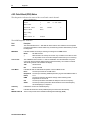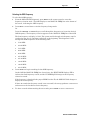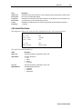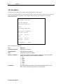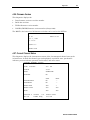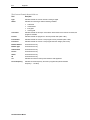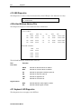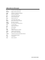
1
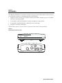
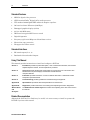
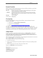
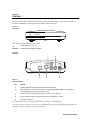
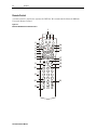
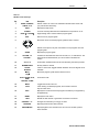
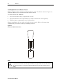
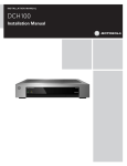
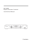
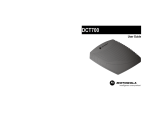
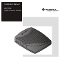
Installation Manual DCT700 Digital Consumer Terminal Graphical symbols and supplement warning marking locations on the bottom of the appliance. This symbol indicates that dangerous voltage levels are present within the equipment. These voltages are not insulated and may be of sufficient strength to cause serious bodily injury when touched. The symbol may also appear on schematics. This symbol calls attention to a critical procedure, or means refer to the instruction manual for opening or service information. Only qualified service personnel are to install or service the equipment. The symbol may also appear in text and on schematics. WARNING: TO PREVENT FIRE OR SHOCK HAZARD, DO NOT EXPOSE THIS APPLIANCE TO RAIN OR MOISTURE. CAUTION: TO PREVENT ELECTRICAL SHOCK, DO NOT USE THIS PLUG WITH AN EXTENSION CORD, RECEPTACLE, OR OTHER OUTLET UNLESS THE BLADES CAN BE FULLY INSERTED TO PREVENT BLADE EXPOSURE. FCC Compliance: Federal Communications Commission Radio and Television Interface Statement for a Class ‘B’ Device This equipment has been tested and found to comply with the limits for a Class B digital device, pursuant to part 15 of the FCC Rules. These limits are designed to provide reasonable protection against harmful interference in the residential installation. This equipment generates, uses and can radiate radio frequency energy and, if not installed and used in accordance with the instructions, may cause harmful interference to radio communications. However, there is no guarantee that interference will not occur in a particular installation. If the equipment does cause harmful interference to radio or television reception, which can be determined by turning the equipment off and on, the user is encouraged to try to correct the interference by one of the following measures: ! Reorient or relocate the receiver antenna ! Increase the separation between the equipment and the affected receiver ! Connect the equipment into an outlet or on a circuit different from that to which the receiver is connected ! Consult the dealer or experienced radio/TV technician for help ! Ensure that the cover plate for the security card is secured and tight Changes or modification not expressly approved by the party responsible for compliance could void the user’s authority to operate the equipment. Declaration of Conformity: According to 47 CFR, Parts 2 and 15 for Class B Personal Computers and Peripherals; and/or CPU Boards and Power Supplies used with Class B Personal Computers, Motorola, Inc., 6450 Sequence Drive, San Diego, CA 92121, 1-800-225-9446, declares under sole responsibility that the product identifies with 47 CFR Part 2 and 15 of the FCC Rules as a Class B digital device. Each product marketed is identical to the representative unit tested and founded to be compliant with the standards. Records maintained continue to reflect the equipment being produced can be expected to be within the variation accepted, due to quantity production and testing on a statistical basis as required by 47 CFR 2.909. Operation is subject to the following condition: This device must accept any interference received, including interference that may cause undesired operation. The above named party is responsible for ensuring that the equipment complies with the standards of 47 CFR, Paragraphs 15.107 to 15.109 Repairs: If repair is necessary, call the Motorola Repair Facility at 1-800-227-0450 for a Return for Service Authorization (RSA) number before sending the unit. The RSA number must be prominently displayed on all equipment cartons. Pack the unit securely; enclose a note describing the exact problem, and a copy of the invoice that verifies the warranty status. Ship the unit PRE-PAID to the following address: Motorola, Inc. Attn: RSA #___________ c/o Rudolph Miles and Sons 2500 Courage Boulevard Brownsville, TX 78521 NOTE TO CATV SYSTEM INSTALLER: This reminder is provided to call CATV system installer’s attention to Article 820-40 of the NEC that provides guidelines for proper grounding and, in particular, specifies that the cable ground shall be connected to the grounding system of the building, as close as possible to the point of cable entry as practical. Copyright © 2003 by Motorola, Inc. All rights reserved. No part of this publication may be reproduced in any form or by any means or used to make any derivative work (such as translation, transformation or adaptation) without written permission from Motorola, Inc. Motorola reserves the right to revise this publication and to make changes in content from time to time without obligation on the part of Motorola to provide notification of such revision or change. Motorola provides this guide without warranty of any kind, either implied or expressed, including, but not limited to, the implied warranties of merchantability and fitness for a particular purpose. Motorola may make improvements or changes in the product(s) described in this manual at any time. STARVUE, MOTOROLA, and the Stylized M Logo are registered in the US Patent & Trademark Office. Manufactured under license from Dolby Laboratories. "Dolby" and the double-D symbol are registered trademarks of Dolby Laboratories. All other product or service names are the property of their respective owners. Contents Section 1 Introduction Standard Features .................................................................................................................................................................. 1-2 Standard Interfaces ................................................................................................................................................................ 1-2 Using This Manual.................................................................................................................................................................. 1-2 Related Documentation .......................................................................................................................................................... 1-2 Document Conventions.......................................................................................................................................................... 1-3 If You Need Help ..................................................................................................................................................................... 1-3 Calling for Repairs.................................................................................................................................................................. 1-3 Section 2 Overview Remote Control....................................................................................................................................................................... 2-2 Installing Batteries in the Remote Control..................................................................................................................... 2-4 Section 3 Installation Before You Begin.................................................................................................................................................................... 3-1 Installing the DCT700 ............................................................................................................................................................. 3-1 Standard Cabling Diagram ..................................................................................................................................................... 3-2 Standard VCR Cabling Diagram ............................................................................................................................................. 3-3 Composite Baseband Cabling Diagrams ............................................................................................................................... 3-4 Stereo Cabling Diagrams (Baseband).................................................................................................................................... 3-6 Operational Check.................................................................................................................................................................. 3-8 Selecting the OOB Frequency........................................................................................................................................ 3-8 Set-top Cold Initialization ....................................................................................................................................................... 3-9 DCT700 Installation Manual ii Contents Section 4 Troubleshooting Appendix A Specifications Appendix B Diagnostics Using Diagnostics.................................................................................................................................................................. B-2 d 01: General Status............................................................................................................................................................... B-3 Error Codes ................................................................................................................................................................... B-5 d 02: Out-of-Band (OOB) Status ............................................................................................................................................ B-6 Selecting the OOB Frequency....................................................................................................................................... B-7 d 03: In-band Status............................................................................................................................................................... B-8 d 04: Audio/Video Status ....................................................................................................................................................... B-9 d 05: Unit Address ............................................................................................................................................................... B-10 d 06: Firmware Version........................................................................................................................................................ B-11 d 07: Current Channel Status .............................................................................................................................................. B-11 d 08: Renewable Security .................................................................................................................................................... B-14 d 09: Upstream Modem (STARVUE II Diagnostics) ............................................................................................................. B-15 d 10: Application (APP) Code Modules ............................................................................................................................... B-15 d 11: Memory Status ............................................................................................................................................................ B-16 d 12: Interactive Info ............................................................................................................................................................ B-17 d 13: MAC Frequency Table................................................................................................................................................. B-18 d 14: Control Channels ........................................................................................................................................................ B-18 d 15: Message Types ........................................................................................................................................................... B-19 d 16: In-Band Program Association Table (PAT)................................................................................................................. B-19 d 17 In-Band Program Map Table (PMT).............................................................................................................................. B-19 d 18: Task Status ................................................................................................................................................................. B-19 d 19: USB Diagnostics ......................................................................................................................................................... B-20 d 20 In-Band Multicast Address Filter ................................................................................................................................. B-20 d 21: Keyboard / LED Diagnostics....................................................................................................................................... B-20 Abbreviations and Acronyms DCT700 Installation Manual Contents iii Figures Figure 1-1 DCT700 set-top front and rear views.................................................................................................................... 1-1 Figure 2-1 Front panel ............................................................................................................................................................ 2-1 Figure 2-2 Rear panel............................................................................................................................................................. 2-1 Figure 2-3 Motorola DRC450 Universal Remote Control....................................................................................................... 2-2 Figure 2-4 Back view of DRC450 remote control .................................................................................................................. 2-4 Figure 3-1 Connecting the DCT700 to a TV using RF connectors ........................................................................................ 3-2 Figure 3-2 Standard VCR cabling .......................................................................................................................................... 3-3 Figure 3-3 Standard baseband cabling ................................................................................................................................. 3-4 Figure 3-4 Baseband audio and video connections to a VCR and TV .................................................................................. 3-5 Figure 3-5 Audio on the VCR................................................................................................................................................. 3-6 Figure 3-6 Audio on VCR/Audio output on TV ...................................................................................................................... 3-7 Tables Table 2-1 Rear panel features................................................................................................................................................ 2-1 Table 2-2 DRC450 remote control keys................................................................................................................................. 2-3 Table 3-1 Operational check procedures .............................................................................................................................. 3-8 Table 4-1 Troubleshooting guidelines................................................................................................................................... 4-1 DCT700 Installation Manual Section 1 Introduction The Motorola DCT700 is an interactive digital consumer terminal that enables cable operators to cost-effectively deploy an all-digital network. The DCT700: ! Supports services such as an electronic program guide (EPG), impulse pay-per view (IPPV), and video on demand (VOD) ! Is compatible with existing Motorola analog and digital set-top products ! Is compatible with MediaCipher conditional access technology ! Provides a real-time return path The DCT700 requires a remote control to operate (remote control sold separately). Figure 1-1 DCT700 set-top front and rear views ON MESSAGES TO TV/VCR L +12V DC R RF IN AUDIO VIDEO DCT700 Installation Manual 1-2 Introduction Standard Features ! MPEG-2 digital video processor ! ATSC standard Dolby® Digital (AC-3) audio processor ! ITU standard 64/256 QAM FEC enhanced adaptive equalizer ! On-board real-time RF return (256 Kbps) ! Bitmapped graphics display (4/8-bit) ! 88.75 to 858 MHz tuner ! DES based encryption/DCII access control ! Digital diagnostics ! Frequency agile 2.048 Mbps out-of-band data receiver ! Macrovision copy protection ! IR support for remote control Standard Interfaces ! RF remod output (ch. 3, 4) ! Baseband video and audio Outputs Using This Manual This manual provides instructions to install and configure a DCT700: Section 1 Introduction provides a product description, a list of related documentation, the technical helpline telephone number, and the repair/return procedure. Section 2 Overview describes the DCT700 and provides an overview of its use. This section also identifies the front-panel displays and switches and describes the rear-panel features. Section 3 Installation provides instructions on how to install the DCT700 in a subscriber location and perform operational tests. Section 4 Troubleshooting provides guidelines for troubleshooting the equipment. Appendix A Specifications provide the technical specifications for the DCT700. Appendix B Diagnostics provide instructions on accessing and interpreting the built-in diagnostics. Abbreviations and Acronyms The Abbreviations and Acronyms list contains the full spelling of the short forms used in this manual. Related Documentation Although the DCT700 User Guide may be useful, it is not necessary to install or operate the DCT700 if you have this manual. DCT700 Installation Manual Introduction 1-3 Document Conventions Before you begin working with this manual and using the DCT700, familiarize yourself with the stylistic conventions used in this manual: SMALL CAPS Denotes silk screening on the equipment, typically representing front- and rear-panel controls, input/output (I/O) connections, and LEDs * (asterisk) Indicates that several versions of the same model number exist and the information applies to all models; when the information applies to a specific model, the complete model number is given Italic type Used for emphasis Courier font Displayed text If You Need Help If you need assistance while working with the DCT700, contact the Motorola Technical Response Center (TRC): ! Inside the U.S.: 1-888-944-HELP (1-888-944-4357) ! Outside the U.S.: 215-323-0044 ! Online: http://broadband.motorola.com/noflash/websupport.html. The TRC is open from 8:00 AM to 7:00 PM Eastern Time, Monday through Friday and 10:00 AM to 5:00 PM Eastern Time, Saturday. When the TRC is closed, emergency service only is available on a call-back basis. Web Support offers a searchable solutions database, technical documentation, and low priority issue creation/tracking 24 hours per day, 7 days per week. Calling for Repairs If repair is necessary, call the Motorola Repair Facility at 1-800-227-0450 for a Return for Service Authorization (RSA) number before sending the unit. The RSA number must be prominently displayed on all equipment cartons. The Repair Facility is open from 8:00 AM to 5:00 PM Central Time, Monday through Friday. When calling from outside the United States, use the appropriate international access code and then call 956-541-0600 to contact the Repair Facility. When shipping equipment for repair, follow these steps: 1 Pack the unit securely. 2 Enclose a note describing the exact problem. Complete and enclose the checklist provided with the unit. 3 Enclose a copy of the invoice that verifies the warranty status. Ship the unit PREPAID to the following address: Motorola, Inc. Broadband Communications Sector Attn: RSA #___________ c/o Rudolph Miles and Sons 2500 Courage Boulevard Brownsville, TX 78521 DCT700 Installation Manual Section 2 Overview This section describes the DCT700’s displays and connectors. Before you begin to install the DCT700, familiarize yourself with these displays and connectors. Figure 2-1 Front panel ON MESSAGES The DCT700 front panel has two LEDs: ON Indicates that the unit is on MESSAGES Indicates that a message is present Figure 2-2 Rear panel 2 1 TO TV/VCR L +12V DC R AUDIO RF IN 3 VIDEO 4 5 Table 2-1 Rear panel features Key Function 1 Left and right audio RCA jacks used for stereo audio output. 2 RCA jack used to connect the DCT700 to a composite (baseband) video TV or a monitor; in some configurations this jack connects to a VCR. 3 F-type connector used for DCT700 input from the TO RF IN connector. 4 F-type connector used to connect the DCT700 to a standard TV or VCR. 5 DC power connection. For instructions on connecting the DCT700, see Section 3, “Installation.” A remote control is required to operate the DCT700. We recommend the Motorola DRC450. See “Remote Control” in this section for information. DCT700 Installation Manual 2-2 Overview Remote Control A remote control is required to operate the DCT700. We recommend the Motorola DRC450 Universal Remote Control: Figure 2-3 Motorola DRC450 Universal Remote Control 1 AUDIO 2 3 4 5 6 7 8 VCR/DVD CABLE HELP POWER PAGE 11 12 13 DCT700 Installation Manual LOCK PAGE EXIT INFO 14 15 16 OK MENU VOLUME 9 10 TV LAST CHANNEL FAVORITE A B C 1 2 3 4 5 6 7 8 TV/VCR REW PAUSE RECORD 20 9 ENTER 0 DAY STOP 17 18 19 DAY PLAY F.FWD 21 Overview 2-3 Table 2-2 DRC450 remote control keys Key Item 1 AUDIO, VCR/DVD, CABLE, or TV 2 HELP 3 POWER 4 PAGE ▲ or PAGE▼ ▼ 5 EXIT 6 Description Selects a device to control. The selected mode will remain active until you press another device key. Displays the help screen. Turns the currently selected home entertainment component on or off. Pages through menu screens and the program guide. Exits a menu or program guide. Moves the cursor around the program guide and menu screens. 7 OK 8 GUIDE 9 VOLUME + or VOLUME - Increases or decreases the volume of the VCR, TV, or audio device. The device must be selected before you can increase or decrease the volume. 10 A, B, or C Functionality is determined from services offered by the service provider. 11 NUMBER KEYS 12 TV/VCR BYPASS 13 ◄ Day Day ► STOP, PAUSE, PLAY, REW, RECORD, F.FWD Selects menu options, Pay-Per-View events or tune programs from the program guide. Displays the program guide. Directly selects a channel. When in VCR mode, toggles between television and VCR. Bypass is not available. Moves the program guide ahead or back 24 hours. Controls the VCR. 14 MUTE Toggles the sound on and off. 15 LOCK Limits viewing of selected programs; and is used to view the Pay-Per-View menu. 16 INFO Displays the current channel and program information (not supported by all applications). 17 MENU Displays the main menu. 18 LAST Recalls the last channel or goes back one screen in the menu. 19 CHANNEL + or - 20 FAVORITE 21 ENTER/MUSIC Changes the channels by moving up or down. Displays preset favorite cable channels. Displays digital music channel menus. On some TV models, press to enter channels. DCT700 Installation Manual 2-4 Overview Installing Batteries in the Remote Control Before using the remote control, you must install two AA (1.5 V) alkaline batteries. Figure 2-4 illustrates battery access on the back of the remote control. To install batteries in a DRC450: 1 Press and slide the battery compartment cover off. 2 Place the batteries in the compartment; be careful to observe the correct polarity. 3 Slide the battery compartment cover back into place. Battery installation will vary with each style of remote control. Refer to the instructions included with your remote control for installing batteries. Figure 2-4 Back view of DRC450 remote control + + NOTE! Use and dispose of batteries in accordance with all applicable laws, rules and regulations. Motorola will not be liable to anyone for the user's failure to use and/or dispose of batteries in the proper manner and in accordance with such laws, rules and regulations, or for any defect contained in batteries that may cause injury damage to persons or property. DCT700 Installation Manual Section 3 Installation This section provides instructions for installing and cabling the DCT700. To complete the installation, you must: ! Connect the cables ! Supply power to equipment ! Download configuration information and software ! Run operational check and diagnostics This section also includes the procedure for performing a cold initialization of the DCT700. Before You Begin Before you begin, review the installation instructions, gather the required items, and complete the tasks listed below: ! Verify that you have 75-ohm coaxial cables with F-type connectors and RCA baseband phono-type cables. ! Determine if you are connecting the set-top to a standard TV or a composite (baseband) monitor. ! Place the set-top on a smooth, flat surface and remove any obstructions that could interfere with the free flow of air over, under, or around it. Advise the subscriber not to place anything on top of the unit. Installing the DCT700 To install the DCT700: 1 Determine if you are connecting the set-top to a conventional TV or to a monitor. To install the video connection: ! For a conventional TV, use a 75-ohm coaxial cable with F-type connectors. ! For a monitor, use an RCA phono cable to connect the VIDEO connector to the monitor. 2 Locate the cabling diagram that matches the subscriber’s configuration requirement. 3 Connect the cables as illustrated in the diagram. 4 Perform the basic operational check in this section after the set-top is installed. DCT700 Installation Manual 3-2 Installation Standard Cabling Diagram The DCT700 outputs on either channel 3 or 4 depending on the configuration message from the addressable controller. Figure 3-1 Connecting the DCT700 to a TV using RF connectors From cable outlet DCT700 TO TV/VCR L +12V DC R AUDIO RF IN VIDEO TV AUDIO IN L CABLE IN AUDIO OUT R VIDEO IN S-VIDEO IN VIDEO OUT S-VIDEO OUT The remodulated channel, 3 or 4, does not carry stereo for digital channels. To receive stereo, connect the DCT700 using RCA baseband connectors. These connections are illustrated later in this section. DCT700 Installation Manual Installation 3-3 Standard VCR Cabling Diagram Figure 3-2 illustrates cabling using an RF connector that enables the subscriber to record the channel being viewed: Figure 3-2 Standard VCR cabling From cable outlet DCT700 TO TV/VCR L +12V DC R AUDIO RF IN VIDEO VCR AUDIO IN L R CABLE IN AUDIO OUT L VIDEO IN R CABLE OUT S-VIDEO IN VIDEO OUT S-VIDEO OUT TV AUDIO IN R CABLE IN AUDIO OUT L VIDEO IN S-VIDEO IN VIDEO OUT S-VIDEO OUT The remodulated channel, 3 or 4, does not carry stereo for digital channels. To receive stereo, connect the DCT700 using RCA baseband connectors. These connections are illustrated later in this section. DCT700 Installation Manual 3-4 Installation Composite Baseband Cabling Diagrams Connecting the DCT700 using the baseband RCA type outputs enables the subscriber to experience stereo and Dolby Surround sound when available on digital channels. Figure 3-3 illustrates the standard baseband audio and video outputs of the DCT700: Figure 3-3 Standard baseband cabling DCT700 TO TV/VCR L +12V DC R RF IN AUDIO VIDEO TV AUDIO IN CABLE IN DCT700 Installation Manual L R AUDIO OUT VIDEO IN S-VIDEO IN VIDEO OUT S-VIDEO OUT Installation 3-5 Figure 3-4 Baseband audio and video connections to a VCR and TV DCT700 TO TV/VCR L +12V DC R AUDIO RF IN VIDEO VCR AUDIO IN L R CABLE IN AUDIO OUT L VIDEO IN R CABLE OUT S-VIDEO IN VIDEO OUT S-VIDEO OUT TV AUDIO IN L CABLE IN AUDIO OUT R VIDEO IN S-VIDEO IN VIDEO OUT S-VIDEO OUT DCT700 Installation Manual 3-6 Installation Stereo Cabling Diagrams (Baseband) This audio configuration does not provide for a TV playing through the stereo. Figure 3-5 illustrates how to connect the DCT700 to a stereo using the audio connectors on the VCR: Figure 3-5 Audio on the VCR DCT700 TO TV/VCR L +12V DC R AUDIO RF IN VIDEO VCR AUDIO IN L R CABLE IN AUDIO OUT L VIDEO IN R CABLE OUT S-VIDEO IN VIDEO OUT S-VIDEO OUT STEREO AUDIO IN L AUDIO OUT R TV AUDIO IN L CABLE IN DCT700 Installation Manual AUDIO OUT R VIDEO IN S-VIDEO IN VIDEO OUT S-VIDEO OUT Installation 3-7 This audio configuration enables the TV to play through the stereo. Figure 3-6 shows how to connect the DCT700 to a stereo using the audio loop-through connectors on the VCR and the audio output ports on the TV monitor: Figure 3-6 Audio on VCR/Audio output on TV DCT700 TO TV/VCR L +12V DC R AUDIO RF IN VIDEO VCR AUDIO IN L R VIDEO IN CABLE IN AUDIO OUT L R CABLE OUT S-VIDEO IN VIDEO OUT S-VIDEO OUT TV AUDIO IN L CABLE IN AUDIO OUT R VIDEO IN S-VIDEO IN VIDEO OUT S-VIDEO OUT STEREO AUDIO IN L AUDIO OUT R DCT700 Installation Manual 3-8 Installation Operational Check The operational check tests communications between the remote control and the set-top and verifies the set-top response to remote control commands: Table 3-1 Operational check procedures Feature Testing Procedure Power on 1 Press POWER on the remote control to turn on the set-top. 2 Turn on the TV and tune it to the set-top output channel (3 or 4). Channel Selection Tune to several channels by entering the channel number with the numeric keys on the remote control. If the set-top does not operate properly, refer to Section 4, “Troubleshooting.” Selecting the OOB Frequency Use the Motorola universal remote control to operate the DCT700. To select the OOB frequency: 1 From the O2 OOB STATUS diagnostic, press the MENU button to enter the frequency selection mode. The OSD displays a new MANUAL FREQ line at the bottom of the screen, indicating the LKC frequency. 2 Press the MENU key a second time to exit the frequency change mode. Or Press the UP/DOWN channel or cursor keys to scroll through the frequencies to locate the desired OOB frequency. The frequency selection appears on the MANUAL FREQ line of the OSD. The first frequency to display is 75.25. The system scrolls through each frequency until it reaches the last, 103.75, and then scrolls back to the beginning. This diagnostic scrolls through the OOB frequencies in the following order: ! 75.25 MHz ! 104.20 MHz ! 72.75 MHz ! 92.25 MHz ! 98.25 MHz ! 107.25 MHz ! 107.40 MHz ! 110.25 MHz ! 116.25 MHz ! 103.75 MHz DCT700 Installation Manual Installation 3 3-9 Press SELECT to begin searching for the OOB frequency. On the OSD the MANUAL FREQ line of text clears, the HUNT MODE displays FIX to indicate the fixed frequency search, and the CUR FREQ field changes to the frequency selected to search. If the frequency is found with the proper EMM Provider ID, the OSD LKC field changes to display the new frequency. If after 40 seconds the frequency search is not successful, the set-top performs a warm reset and returns to the last known carrier frequency. 4 To abort a search without waiting the 40 seconds, press POWER to cause a warm reset. Set-top Cold Initialization The DCT700 has no front panel buttons. To perform a cold initialization, or reset, using the remote control: 1 Hold down any key while disconnecting and reconnecting AC power to the set-top. After booting up, the POWER LED on the set-top front panel flashes. 2 Within 3 seconds, press 3. The POWER LED flashes at a decreased rate. 3 Within 3 seconds, press 2. The POWER LED flashes at an increased rate. 4 Within 3 seconds, press 8 to initiate the cold reset. During the cold initialization procedure, if the appropriate remote control key is not pressed within the three-second time period, the procedure terminates and the set-top resumes normal operation. DCT700 Installation Manual Section 4 Troubleshooting This section provides information to assist you in quickly detecting, isolating, and resolving error conditions that might occur when using the DCT700. If you need assistance while working with the DCT700, contact the Motorola Technical Response Center (TRC): ! Inside the U.S.: 1-888-944-HELP (1-888-944-4357) ! Outside the U.S.: 215-323-0044 ! Online: http://broadband.motorola.com/noflash/websupport.html. The TRC is open from 8:00 AM to 7:00 PM Eastern Time, Monday through Friday and 10:00 AM to 5:00 PM Eastern Time, Saturday. When the TRC is closed, emergency service only is available on a call-back basis. Web Support offers a searchable solutions database, technical documentation, and low priority issue creation/tracking 24 hours per day, 7 days per week. Table 4-1 is a list of possible problems and solutions: Table 4-1 Troubleshooting guidelines Problem Possible Solution No power to the DCT700 Check the power outlet for AC power. Be sure the TV is tuned to the output channel of the DCT700 (channel 3 or 4). Verify that cable connections are correct from the TV set or monitor to the DCT700. Check that the power cord is properly plugged into the outlet and DCT700. Remote control is not responding Check for an obstruction between the remote control and the DCT700. Aim the remote control directly at the DCT700, not the TV or VCR. Be sure you firmly and deliberately press and release operation keys one at a time. Check that the DCT700 has been initialized correctly; refer to Diagnostics. Change the batteries in your remote control according to the instructions in Section 2, “Overview”. The DCT700 is not receiving a cable signal Check the cable connections and hand-tighten if necessary. Verify that the cable connections are correct. Verify the TV is working and has a clear picture. Guide has no data Unplug the power to the DCT700 and plug in the unit again. Wait for the DCT700 to collect the data. DCT700 Installation Manual Appendix A Specifications Input frequency 88.75 to 858 MHz (excluding data carrier frequency) HRC/IRC frequency assignments Downloadable Number of channels: 128 carriers per cable; more than one digital channel per carrier, content dependent Average digital input level: 64 QAM –15 dBmV to +15 dBmV 256 QAM –12 dBmV to +15 dBmV Data carrier: Frequency Bandwidth Level QPSK-modulated carrier Agile 1.5 MHz –15 dBmV to +15 dBmV Video signal to noise ratio 57 dB minimum for baseband output, unified weighted, 4.2 MHz bandwidth Remod output frequency accuracy ±80 kHz Return loss: Input Output 4 dB minimum 8 dB minimum Spurious output –57 dBc maximum, in band Remod output level 10 to 15 dBmV Isolation (input/output) 70 dB minimum On-screen display (OSD): Screen size 352 x 480 pixels (configuration dependent) Message/barker capacity Up to 40 pages (configuration dependent) Operating environment range: Temperature Humidity 0° to 40°C (32° to 104°F) 5 to 95% (non-condensing) AC voltage: USA and Canada 105 to 125 V, 60 Hz Mexico 114 to 140 V, 60 Hz Power dissipation 16 W at 115 V Surge protection Provided on power supply and RF ports Size 5.5 x 6.7 x 1.8 inches Weight 0.85 pounds DCT700 Installation Manual Appendix B Diagnostics This section describes the on-screen diagnostics to confirm proper DCT700 installation, including: ! Checking error states and signal integrity ! Identifying the set-top on the network ! Verifying communications with the headend For the diagnostics provided here: ! All indicators are in decimal notation unless otherwise noted. ! All screens self-refresh at a minimum rate of once every five seconds. ! All sample displays are illustrative; actual data will differ from the examples. Preliminary DCT700 Installation Manual B-2 Diagnostics Using Diagnostics To access and navigate the diagnostics using the Motorola universal remote control: 1 Press POWER to turn on the set-top. 2 Wait five seconds and then press POWER again to turn off the set-top. 3 To enable diagnostic mode, press OK within two seconds after powering off. The DIAGNOSTICS main menu is displayed on the OSD: DIAGNOSTICS 01 GENERAL STATUS 02 OOB STATUS 03 IN BAND STATUS 04 AUDIO/VIDEO STATUS 05 UNIT ADDRESS 06 FIRMWARE VERSION 07 CURRENT CHANNEL STATUS 08 RENEWABLE SECURITY 09 UPSTREAM MODEM 10 APP CODE MODULES 11 MEMORY CONFIG 12 INTERACTIVE INFO 13 MAC FREQUENCY TABLE 14 CONTROL CHANNELS 15 MESSAGE TYPES 16 IN BAND PAT 17 IN BAND PMT 18 TASK STATUS 19 USB STATUS 20 IB MCA STATUS 21 KEYBOARD / LED 4 Use the CHANNEL or cursor keys to select the desired diagnostic. 5 Press cursor <, cursor >, ENTER, or OK to run the selected diagnostic. 6 To exit the diagnostic mode, press POWER on the remote control. The set-top exits the diagnostic mode and powers off. DCT700 Installation Manual Diagnostics B-3 The complete list of remote control buttons you can use to navigate the diagnostics is: Button Function using the diagnostics main menu Function using a diagnostic POWER Exits diagnostic mode and enters OFF state Exits diagnostic mode and enters OFF state CH/CUR +, CURSOR UP Moves the cursor up Displays the DIAGNOSTICS main menu CH/CUR - , CURSOR DOWN Moves the cursor down Displays the DIAGNOSTICS main menu CURSOR RIGHT, CURSOR LEFT, OK, ENTER Runs the selected diagnostic Displays the DIAGNOSTICS main menu GUIDE None None MENU None None INFO None None d 01: General Status This diagnostic displays the error code, a short description of the error, the purchase count, and specific model information: DCT700 STATUS ERROR : E 00 NO ERROR PURCHASES : 0 Platform ID: : 0x0060 Family ID Model ID : 0x0000 : 0x008F TUNER : tuner type Remod Channel Time Zone (hhhhhhhh) : 3 MMMM min DS Entry Time 1/1/1999 00:00 GMT DS Exit Time 1/1/1999 00:00 GMT Current GPS Time 1/1/1999 00:00 GMT DCT700 Installation Manual B-4 Diagnostics The General Status fields are: Field Description Error Codes A sequence of LED flashes communicates errors when they occur. The Error Code field displays the code for the active error when appropriate. Purchases Indicates the number of unreported purchases. Platform ID A 16-bit hexadecimal number used to differentiate between digital platform images in the field. It is also called the ROM ID. Family ID A hexadecimal number that indicates the set-top manufacturer and product family. Model ID A hexadecimal number that indicates the set-top model. Tuner Indicates the tuner type. Remod Channel The Remod Channel can be 3 or 4 (NA systems). The output port configuration displays the configuration of the set-top output or re-modulated (remod) port. The output port/remod port is the interface from the set-top to the subscriber TV. Time Zone Indicates the time zone offset (in minutes) relative to GMT. DS Entry Time Indicates the daylight savings entry time. DS Exit Time Indicates the daylight savings exit time. Current GPS Time Indicates the current time. DCT700 Installation Manual Diagnostics B-5 Error Codes A sequence of LED flashes communicates errors when errors occur. The errors associated flash sequences, causes, and remedies are: Code Flash Sequence Cause Remedy E 00 None; no error condition exists Indicates normal condition after initialization Not applicable E 01 MESSAGES The set-top did not receive a connect message Restore out-of-band signal Send a connect message E 02 Repeating series of two MESSAGES LED flashes, separated by a pause Init Error The set-top needs a power cycle to recover E 03 Repeating series of three LED flashes, separated by a pause DRAM error Not used at this time E 04 Repeating series of four MESSAGES LED flashes, separated by a pause DP-SRAM error Not used at this time E 07 Repeating series of seven LED flashes, separated by a pause ROM verification failure Power cycle the set-top; if repetitive, return for repair E 08 Repeating series of eight MESSAGES LED flashes, separated by a pause Faulty RAM, ROM, EEPROM, or POST failure (this is a hardware failure) Return the set-top for repair E 09 Repeating series of nine MESSAGES LED flashes, separated by a pause Dead battery or the memory has not been initialized; occurs if the battery fails to keep the RAM alive during power-down; causes set-top to be disconnected Return the set-top for repair; requires factory initialization message E 10 POWER LED flashes on and MESSAGES LED remains off Invalid serial number Not used at this time E 11 POWER LED flashes once; MESSAGES LED flashes once Invalid unit address Return the set-top for repair; requires a unit creation message E 12 POWER LED flashes once; MESSAGES LED flashes twice POST failed Not used at this time E 13 POWER LED flashes once; MESSAGES LED flashes three Sys_boot initialization failure Power cycle the set-top; if repetitive, return for repair System startup failure Power cycle the set-top; if repetitive, return for repair TSI structure is corrupted Power cycle the set-top; if repetitive, return for repair Bad flash number specified for Initiate Flash Platform Error logged, ignore Bad platform validation step number Error logged, ignore LED flashes on and off MESSAGES MESSAGES E 14 E 15 E 16 E 17 off; times POWER LED flashes once; MESSAGES LED flashes four times POWER LED flashes once; MESSAGES LED flashes five times POWER LED flashes once; MESSAGES LED flashes six times POWER LED flashes once; MESSAGES LED flashes seven times Only the ALPS TDER1-0001 A appears on the on-screen display. DCT700 Installation Manual B-6 Diagnostics d 02: Out-of-Band (OOB) Status This diagnostic indicates the status of the out-of-band control channel. OOB DIAGNOSTIC DATA * EMM DATA * CARRIER LOCK YES HUNT MODE None SNR COUNT 23 dB GOOD 1 CUR FREQ LKC EMM PRVDR ID 0x0001 The OOB Diagnostic fields are: Field Description Data The OSD indicates with a “*” that data has been received. The indicators cover all packet processors regardless of which stream they are monitoring and are cleared when you enter the diagnostic. EMM Data Indicates whether the set-top is receiving a message on the EMM stream: Blank No data received. Data received. The set-top can receive only 12 PIDs at once. Data on PIDs * can be present on the out-of-band multiplex that the set-top is not receiving. Carrier Lock The CARRIER LOCK is reset to “1” after an initialization from the DAC 6000 or a power cycle. Each time the set-top detects a drop in OOB connectivity, the counter increments. The following Carrier Lock variables can display: YES Carrier locked NO Carrier unlocked Hunt Mode Indicates the state of OOB stream acquisition. The Hunt Mode can be: None The set-top is locked to an OOB carrier. RR (Round The set-top is searching OOB frequencies trying to find an EMM Provider of Robin) 0 or 1. EMM The set-top received a Provider ID change and is searching OOB frequencies for the new ID. FIX The set-top has been commanded to attempt to lock onto a frequency. SRCH The set-top at some point had a valid Provider ID on the OOB frequency and is attempting to re-acquire it. CUR Freq Indicates the current out-of-band frequency. LKC Indicates the last known carrier (OOB frequency that had correct Provider ID). EMM Provider ID The ID of the provider of the Entitlement Management Message (EMM). DCT700 Installation Manual Diagnostics B-7 Selecting the OOB Frequency To select the OOB frequency: 1 From the OOB STATUS diagnostic, press MENU on the remote control to enter the frequency selection mode. The OSD displays a new MANUAL FREQ line at the bottom of the screen, indicating the LKC frequency. 2 Press MENU a second time to exit the frequency change mode. Or Press the CHANNEL or cursor keys to scroll through the frequencies to locate the desired OOB frequency. The frequency selection appears on the MANUAL FREQ line of the OSD. The first frequency to display is 75.25. The system scrolls through each frequency until it reaches the last, 103.75, and then scrolls back to the beginning. This diagnostic scrolls through the OOB frequencies in the following order: 3 ! 75.25 MHz ! 104.20 MHz ! 72.75 MHz ! 92.25 MHz ! 98.25 MHz ! 107.25 MHz ! 107.40 MHz ! 110.25 MHz ! 116.25 MHz ! 103.75 MHz Press SELECT to begin searching for the OOB frequency. On the OSD the MANUAL FREQ line of text clears, the HUNT MODE displays FIX to indicate the fixed frequency search, and the CUR FREQ field changes to the frequency selected to search. If the frequency is found with the proper EMM Provider ID, the OSD LKC field changes to display the new frequency. If after 40 seconds the frequency search is not successful, the set-top performs a warm reset and returns to the last known carrier frequency. 4 To abort a search without waiting the 40 seconds, press POWER to cause a warm reset. DCT700 Installation Manual B-8 Diagnostics d 03: In-band Status This diagnostic displays for the last attempted channel tune. If a digital carrier is not present, the diagnostics indicate the carrier lock is analog. When the carrier lock is analog, all fields for digital (other than a carrier lock channel) are blank. IN BAND DIAGNOSTIC DATA * EMM DATA * CARRIER LOCK YES PCR LOCK YES SNR 36 dB ssss MODULATION MODE QAM 64 SHORT TERM ERROR COUNT 0000 LONG TERM ERROR COUNT 9999 TUNED FREQ 543.000 The In-band Diagnostic fields are: Field Description Data Activity Indicator Lights when the set-top is receiving data on the in-band channels. The indicator covers all packet processors regardless of which stream they are monitoring. The following variables can display: Blank No data received Data received * EMM Data Indicator Lights when the set-top is receiving a message on the EMM stream. The indicator is clear when entering this diagnostic. The following variables can display: Blank No data received Data received * Carrier Lock Indicates that the digital in-band receiver is locked to the carrier with the following variables: YES Carrier locked NO Carrier unlocked Analog Analog channel PCR Lock Indicates a program-clock-reference lock with the current digital data stream. SNR Displays an estimate of the carrier signal-to-noise ratio. The SNR displayed is a measure of the QAM cluster variance, which is proportional to the SNR. Analog channels display analog for carrier lock. The SNR displays a number for the numeric value and blank for the ssss value. The following variables can display: Blank The digital section is still in the initial state. If this occurs, check diagnostic d07. Modulation Mode GOOD Good value FAIR Marginal signal level; check the signal POOR Unusable signal Indicates the modulation mode — QAM 64 or QAM 256 DCT700 Installation Manual Diagnostics B-9 Field Description Short Term Error Count Indicates the FEC errors (maximum count of 65535) at 5-second intervals. The Short Term Error Count is cleared after polling. Long Term Error Count Indicates the accumulation of the Short Term Error Count (maximum count of 65535). The Long Term Error Count is cleared every 24 hours. Tuned Frequency Indicates the actual frequency the tuner is programmed (Carrier Definition Frequency + 1.75 MHz). d 04: Audio/Video Status This diagnostic displays the audio and video information for the current tuned channel: AUDIO/VIDEO STATUS ADP Lock YES Audio Mode STEREO Audio SPDIF N/A VP Lock YES MPEG Method MUTE BLACK The Audio Video Status fields are: Status Description ADP Lock The Audio Processor locked status: YES or NO Audio Mode The audio modes are: N/A Mono Stereo Surround ! ! ! ! VP Lock The Video Processor locked status: YES or NO MPEG Method The MPEG Method selected: ! Unmuted ! Mute Still ! Mute Black DCT700 Installation Manual B-10 Diagnostics d 05: Unit Address This diagnostic displays the 16-digit (40-bit) unit address of the set-top. On the unit address OSD, the unit, network, and TV PassCard (TVPC) addresses are in decimal form (13 address digits and three check digits). The multicast 16-bit address is in TCP/IP decimal byte form. DCT700 UNIT ADDRESS: 000-02831-99902-038 Network Address: 085-14316-55765-159 TVPC: 000-00000-00000-000 Multicast 16 Address: 085.085 119.119 102.102 136.136 DATA 068.068 051.051 034.034 017.017 Seed Health 0xFF The Unit Address fields are: Field Description DCT700 Unit Address Indicates the unit address Network Address Indicates the network address TVPC Indicates the TV Passcard Address. Multicast 16 Address The Multicast 16 address numbers change to display the values for each data stream. The following is a list of Multicast 16 addresses: ! NET ! EMM ! SCC ! DWLD ! DATA ! VCN ! POLL Seed Health This value represents the health of the set-top and should be 0xFF. If it is not 0xFF, see the “Troubleshooting” section for more information. DCT700 Installation Manual Diagnostics B-11 d 06: Firmware Version This diagnostic displays the: ! Dena firmware version or revision number ! Build date and time ! TSODA firmware version number ! CAMEL (CMLBK) firmware version number (always 0000) The BOOT is the lowest level of firmware code that can be used on the DCT700. FIRMWARE VERSION 02.06 BOOT 02.03 Oct 6, 2003 19:18:46 TSODA t16 CMLBK 0000 d 07: Current Channel Status This diagnostic displays the instantaneous status of the last attempted channel tune on the in-band tuner. It shows the channel type (analog/digital), acquisition state, purchasable indicator, preview indicator, parental control status, and mute status. CURRENT CHANNEL STATUS TYPE DIGITAL aaa bb STATUS ccccc dddd CONNECTED PREVIEW NO CURR NEXT PURCHASABLE NO -- PURCHASED NO -- EPOCH NUM 0X0 1 EPOCH TYPE 0x0 0x0 AUTH 0X0 0X0 SERVICE 0 STATUS 1 ID CH 204 TUNED FREQ 0X0004 0X00 543.000 DCT700 Installation Manual B-12 Diagnostics The Current Channel Status fields are: Field Description Type Indicates whether the current channel is analog or digital. Status Indicates the channel type with the following variables: ! ! ! ! Authorized Unauthorized Encrypted Connected Unencrypted Indicates whether the set-top is connected or disconnected. If the value is connected, the program is viewable. Preview Indicates whether the program is in the free preview state (YES or NO). Purchasable Indicates whether the current or next program can be purchased (YES or NO). Purchased Indicates whether the current or next program has been bought (YES or NO). EPOCH Number For Motorola use only. EPOCH Type For Motorola use only. Authorization For Motorola use only. Service For Motorola use only. Status For Motorola use only. ID For Motorola use only. CH Indicates the channel currently tuned when the OSD appeared. Tuned Frequency Indicates the actual frequency the tuner is programmed (Carrier Definition Frequency + 1.75 MHz). DCT700 Installation Manual Diagnostics B-13 The CURRENT CHANNEL STATUS variables are: OSD Variable State aaa ENC UNE FWK FPK bb Current epoch authorization reason in the current_epoch_auth_reason field. This is displayed in hex: 00 missing program re-key 01 missing working key epoch message 02 missing event blackout message 03 missing category rekey 04 old category sequence in program, rekey message 10 program bought 11 program bought without taping 12 subscribed with taping 13 subscribed without taping 14 subscribed with taping purchasable 15 IPPV with taping 16 IPPV without taping 20 bad seed checksum 21 bad debit buffer checksum 30 IPPV not enabled 31 insufficient credit to purchase 32 show count limit exceeded 33 debit register will overflow 34 no AFP records available 36 maximum package cost exceeded 37 no IPPV overlay in message 40 not subscribed 41 regional blackout 42 event blackout ccccc INIT − Initialized state CONFI − Configured ACQUI − Acquiring the program AUTH − Authorized for the program Not A − Not authorized for the program ddd blank − Connected NOT − Not connected encrypted unencrypted fixed key fixed program key DCT700 Installation Manual B-14 Diagnostics d 08: Renewable Security This diagnostic includes a TVPC card that returns the security status to current. RENEWABLE SECURITY TVPC NOT REQUIRED CRYPTO NOT MATED STATUS 00 VERSION 00 The Renewable Security fields are: Field Description TVPC Required / Not Required Indicates whether further operation of the set-top requires the TVPC. CRYPTO Lists the current mode as displayed on the CRYPTO OSD (Stand Alone, Support, or Not Mated). Status Indicates the TVPC status: 00 OK 01 TVPC communication problem 02 TVPC required 03 Validator does not match between GK and TVPC 04 Invalid unit key number 05 Old TVPC unit address 0a TVPC not mated 0b TVPC /base module unit address mismatch 0C New TVPC, but wrong version number 0d TVPC unit address mismatch Version Indicates the version of renewable security being used. DCT700 Installation Manual Diagnostics B-15 d 09: Upstream Modem (STARVUE II Diagnostics) This diagnostic shows the status and operating parameters for the STARVUE II RF return: STARVUE II DIAGNOSTICS STATUS: FREQUENCY: LEVEL: IPPV: DISABLED 23.000 MHz 39 DISABLED 170 20:49:33 6-15-01 The STARVUE II Diagnostics fields are: Field Description Status Indicates the transmitter status: Idle t Transmitting Frequency Indicates the transmitting frequency. Level Indicates the approximate power value of the STARVUE II transmitter in dBmV. The difference between the power value on the diagnostic screen and the actual power of the STARVUE II module may be ± 5 dBmV. IPPV Indicates the Interactive Pay-Per-View status with the following variables: IPPV enabled ENABLED UNSENT − ## DISABLED Last Line The set-top contains unsent IPPV transactions. The variable −## is the number of unsent transactions. IPPV disabled Displays the sequence number, time, and date of the last poll message. d 10: Application (APP) Code Modules This diagnostic displays the currently downloaded code modules. This can be a multi-page display. Press SELECT to display additional pages. This is an example of an OSD screen for a set-top that contains ROM: APP CODE MODULES ASTB xxxx aaa bbb ccc MODULE VER STATUS ID 0-8-0772 07.72 ENABLED 0001 Appl_____ 02.00 DOWNLD 07DA DCT700 Installation Manual B-16 Diagnostics The Application Code Modules fields are: Field Description ASTB xxxx indicates: ! ! ! INVD — Not configured for code suite downloads ! ! ! aaa — The code suite list ID VALD — Configured for code suite downloads BLDG — Building code suite If xxxx is VALD or BLDG: bbb — The code suite list version ccc — The code suite time remaining Module Indicates the object name Version Indicates the object version Status The available modes are: ! LOADING ! DELETED ! ENABLING ! ENABLED ! DSABLNG ! DISABLD ! DELETNG ! POSTPND ! ENNORUN ! DISNORUN Indicates the object AppID ID d 11: Memory Status This diagnostic displays the set-top memory status. The format depends on the installed memory types. MEMORY STATUS EEPROM VER.NO. 00.00 PLATFORM APPLICATION NVMEM 238k 20k DRAM 8192k 8192k FLASH 1408k 2048k The Memory Status fields are: Field Description EEPROM Version Number Indicates the EEPROM version (never used, should always be 00.00). Platform Indicates sizes of memory types allocated to platform code. Application Indicates sizes of memory types allocated to application code. System Heap Indicates breakdown of DRAM allocations. DCT700 Installation Manual Diagnostics B-17 d 12: Interactive Info This diagnostic tool gathers data about your system: INTERACTIVE INFO IP : 0.0.0.0 UPM : 0X000021 UPSTREAM ID : 0X0000 DOWNSTREAM ID : 0X0000 STATE : UNCONFIG MAC ABORT CNTR : 0000 GOOD PACKETS: ERROR PACKETS: SOCKET PORT STATE 0 UNUSED 1 UNUSED 2 UNUSED 3 UNUSED 4 UNUSED 5 UNUSED The Interactive Info fields are: Field Description IP Indicates the set-top IP address assigned by the NC 1500, in dotted-decimal format; for example, xxx.xxx.xxx.xxx where each xxx ranges from 000 to 255. UPM Indicates the upstream modem address. This UPM value is the same as the terminal ID assigned by the DAC 6000. The UPM is a unique, system-generated, eight-digit integer between 1 and 16777215 displayed in hexadecimal format. Upstream ID The set-top transmission parameter assigned by the DAC 6000. It is a four-digit value ranging from 0000 to 9999 displayed in hexadecimal format. Downstream ID The set-top transmission parameter assigned by the DAC 6000. It is a four-digit value ranging from 0000 to 9999 displayed in hexadecimal format. State The state modes are: ! MAC CONNECT ! UNCONFIG ! INIT_WAIT_DC_OR_ ! WAIT_LM_ACK ! WAIT_SO_ACK ! WAIT_LA_OR_SO ! INIT_STOPPED ! RUN_WAIT-DC-OR-C ! RUNNING ! RUN_STOPPED ! INVALID DCT700 Installation Manual B-18 Diagnostics Field Description MAC Abort Cntr The MAC Abort Counter increments every time the MAC layer reaches the Cell Abort Count limit. The MAC Abort Counter is reset by the successful upstream transmission of a cell, for example, when an ACK is received by the set-top. Good Packets Not implemented. Error Packets Not implemented. Socket Port State The Socket Port State modes are: ! UNUSED ! OPENED ! READY ! RECVING ! SENDING d 13: MAC Frequency Table The set-top uses a range of frequencies set by the host for upstream communications. The MAC FREQUENCY TABLE that displays your frequency and signal power: MAC FREQUENCY TABLE FREQ POWER The MAC Frequency Table fields are Field Description Frequency Indicates the frequency, in Hz, for an upstream channel. Power Indicates the power level, in dBmV, used on a particular upstream channel to send data to the RPD. d 14: Control Channels This diagnostic lists channels, band types, PIDs, and counts. Control Channel Info CHN BAND PID Cnt Ovfl Err 0 INB 0000 1 0 0 1 INB 00A9 2198 0 0 OOB 0777 15207 1 0 . . 8 DCT700 Installation Manual Diagnostics B-19 d 15: Message Types This diagnostic displays a listing of PIDs and counts. In addition the message types with IDs and counts are shown: Message Types (hex data) Msg Id Cnt Msg Id Cnt 0 - 216 9A E 0 1 2 89 A0 15 0 The Message Types fields are: Field Description Msg The message type ID The connection ID Cnt The number of messages received of this type d 16: In-Band Program Association Table (PAT) This diagnostic displays the Program Association Table Information. (For Motorola use only.) IN BAND PAT (hex data) PAT SN PID 001 0001 0029 d 17 In-Band Program Map Table (PMT) This diagnostic displays the Program Map Table information. (For Motorola use only.) IN BAND PMT (hex data) PMT TYPE PID PCR 0210 001 0080 0210 ECM 0211 d 18: Task Status This diagnostic displays a listing of tasks. (For Motorola use only.) TASK STATUS (hex data) TID RID PRI STARTS RUNTIME STK% 64 00 2 21553 47441 26 63 … 0 DCT700 Installation Manual B-20 Diagnostics d 19: USB Diagnostics This diagnostic is used to verify the functionality of the USB port. (For Motorola use only) USB DIAGNOSTICS NOT INSTALLED d 20 In-Band Multicast Address Filter This diagnostic displays in-band multicast filter information: IN BAND MULTICAST ADDRESS FILTER Filter Table: DMCA MCA PQ RQ APP NA 0000 0000 -01 -01 0000 0000 0000 NA 0000 0000 -01 -01 0000 0000 0000 NA 0000 0000 -01 -01 0000 0000 0000 NA 0000 0000 -01 -01 0000 0000 0000 REGISTER VALUES: MCA PID 0000 0000 0000 0000 0000 0000 0000 0000 The In-Band Multicast Address Filter fields are: Field Description Filter Table DMCA Indicates the default multicast 16 address. MCA Indicates the current multicast 16 address. PQ Indicates the preemption notification queue ID. RQ Indicates the response queue ID. APP Indicates the application ID. CID Indicates the connection ID. MCA Indicates Multicast 16 filter register contents. PID Indicates PID filter register contents. Register Values d 21: Keyboard / LED Diagnostics This diagnostic does not apply to the DCT700. DCT700 Installation Manual CID Abbreviations and Acronyms CSR Customer Service Representative DCT700 Digital Consumer Terminal 700 EMM entitlement management message(s) EPG electronic program guide HRC harmonically related carriers IPG interactive program guide IPPV impulse pay-per-view IRC incrementally related carriers MPAA Motion Picture Advisory Association NVOD Near Video on Demand NVRAM Non-volatile random-access memory OSD on-screen display PCR program clock reference PID packet identifier PPV Pay-Per-View QAM quadrature amplitude modulation QPSK quadrature phase shift keying RSA Return for Service Authorization TCP/IP Transmission Control Protocol/Internet Protocol TRC Technical Response Center TvPC TV PassCard VOD video on demand DCT700 Installation Manual Visit our website at: www.motorola.com 496730-001 12/03 MGBI