1
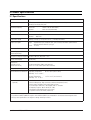
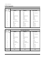
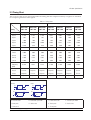
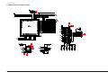
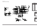
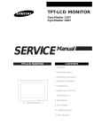
COLOR MONITOR
SyncMaster 570BTFT
SyncMaster 580BTFT
(RN15MSS / RN15MST
RN15MOS / RN15MOT)
SERVICE
Manual
COLOR MONITOR
CONTENTS
1. Precautions
2. Product Specifications
3. Disassembly & Reassembly
4. Troubleshooting
5. Exploded View & Parts List
6. Electrical Parts List
7. Block Diagram
AUTO
EXIT
MENU
8. Wiring Diagram
9. Schematic Diagrams
1 Precautions
Follow these safety, servicing and ESD precautions to prevent damage and to protect against potential hazards such as
electrical shock.
1-1 Safety Precautions
1-1-1 Warnings
1.
For continued safety, do not attempt to modify the
circuit board.
2.
Disconnect the AC power and DC Power Jack
before servicing.
3.
(READING SHOULD
NOT BE ABOVE 0.5mA)
When the chassis is operating, semiconductor
heatsinks are potential shock hazards.
TEST ALL
EXPOSED METAL
SURFACES
1-1-2 Servicing the LCD Monitor
1.
2.
1-1-3 Fire and Shock Hazard
Before returning the monitor to the user, perform the
following safety checks:
1.
Inspect each lead dress to make certain that the
leads are not pinched or that hardware is not
lodged between the chassis and other metal parts in
the monitor.
2.
Inspect all protective devices such as nonmetallic
control knobs, insulating materials, cabinet backs,
adjustment and compartment covers or shields,
isolation resistor-capacitor networks, mechanical
insulators, etc.
3.
2-WIRE CORD
When servicing the LCD Monitor, remove the static
charge by connecting a 10k ohm resistor in series
with an insulated wire (such as a test probe)
between the chassis and the anode lead.
(Disconnect the AC line cord from the AC outlet.)
It is essential that service technicians have an
accurate voltage meter available at all times. Check
the calibration of this meter periodically.
Leakage Current Hot Check (Figure 1-1): WARNING:
Do not use an isolation transformer during this test.
Use a leakage current tester or a metering system
that complies with American National Standards
Institute (ANSI C101.1, Leakage Current for
Appliances), and Underwriters Laboratories (UL
Publication UL1410, 59.7).
SyncMaster 570BTFT / 580BTFT
LEAKAGE
CURRENT
TESTER
DEVICE
UNDER
TEST
ALSO TEST WITH
PLUG REVERSED
(USING AC ADAPTER
PLUG AS REQUIRED)
EARTH
GROUND
Figure 1-1. Leakage Current Test Circuit
4.
With the unit completely reassembled, plug the AC
line cord directly into a 120V AC outlet. With the
unit’s AC switch first in the ON position and then
OFF, measure the current between a known earth
ground (metal water pipe, conduit, etc.) and all
exposed metal parts, including: metal cabinets,
screwheads and control shafts. The current
measured should not exceed 0.5 milliamp. Reverse
the power-plug prongs in the AC outlet and repeat
the test.
1-1-4 Product Safety Notices
Some electrical and mechanical parts have special
safety-related characteristics which are often not
evident from visual inspection. The protection they give
may not be obtained by replacing them with
components rated for higher voltage, wattage, etc. Parts
that have special safety characteristics are identified by
! on schematics and parts lists. A substitute
replacement that does not have the same safety
characteristics as the recommended replacement part
might create shock, fire and / or other hazards. Product
safety is under review continuously and new
instructions are issued whenever appropriate.
1-1
1 Precautions
1-2 Servicing Precautions
WARNING:
An electrolytic capacitor installed with the wrong polarity might explode.
Caution:
Before servicing units covered by this service manual, read and follow the Safety Precautions
section of this manual.
Note:
If unforeseen circumstances create conflict between the following servicing precautions and any of the
safety precautions, always follow the safety precautions.
1-2-1 General Servicing Precautions
1.
2.
3.
Always unplug the unit’s AC power cord from the
AC power source and disconnect the DC Power
Jack before attempting to:
(a) remove or reinstall any component or assembly,
(b) disconnect PCB plugs or connectors, (c) connect
a test component in parallel with an electrolytic
capacitor.
Some components are raised above the printed
circuit board for safety. An insulation tube or tape
is sometimes used. The internal wiring is
sometimes clamped to prevent contact with
thermally hot components. Reinstall all such
elements to their original position.
4.
Check the insulation between the blades of the AC
plug and accessible conductive parts (examples:
metal panels, input terminals and earphone jacks).
5.
Insulation Checking Procedure: Disconnect the
power cord from the AC source and turn the power
switch ON. Connect an insulation resistance meter
(500 V) to the blades of the AC plug.
The insulation resistance between each blade of the
AC plug and accessible conductive parts (see
above) should be greater than 1 megohm.
6.
After servicing, always check that the screws,
components and wiring have been correctly
reinstalled. Make sure that the area around the
serviced part has not been damaged.
Always connect a test instrument’s ground lead to
the instrument chassis ground before connecting the
positive lead; always remove the instrument’s
ground lead last.
1-3 Electrostatically Sensitive Devices (ESD) Precautions
Some semiconductor (solid state) devices can be easily damaged by static electricity. Such components are commonly
called Electrostatically Sensitive Devices (ESD). Examples of typical ESD devices are integrated circuits and some fieldeffect transistors. The following techniques will reduce the incidence of component damage caused by static electricity.
1.
Immediately before handling any semiconductor
components or assemblies, drain the electrostatic
charge from your body by touching a known earth
ground. Alternatively, wear a discharging wriststrap device. To avoid a shock hazard, be sure to
remove the wrist strap before applying power to
the monitor.
6.
Do not remove a replacement ESD from its
protective package until you are ready to install it.
Most replacement ESDs are packaged with leads
that are electrically shorted together by conductive
foam, aluminum foil or other conductive materials.
7.
2.
After removing an ESD-equipped assembly, place it
on a conductive surface such as aluminum foil to
prevent accumulation of an electrostatic charge.
Immediately before removing the protective
material from the leads of a replacement ESD,
touch the protective material to the chassis or
circuit assembly into which the device will be
installed.
3.
Do not use freon-propelled chemicals. These can
generate electrical charges sufficient to damage
ESDs.
Caution: Be sure no power is applied to the
chassis or circuit and observe all
other safety precautions.
4.
Use only a grounded-tip soldering iron to solder or
desolder ESDs.
5.
Use only an anti-static solder removal device. Some
solder removal devices not classified as “anti-static”
can generate electrical charges sufficient to damage
ESDs.
1-2
8.
Minimize body motions when handling
unpackaged replacement ESDs. Motions such as
brushing clothes together, or lifting your foot from
a carpeted floor can generate enough static
electricity to damage an ESD.
SyncMaster 570BTFT / 580BTFT
2 Product Specifications
2-1 Specifications
Item
Description
LCD Panel
TFT-LCD panel, RGB vertical stripe, normaly white, 15-Inch viewable,
0.297 (H) x 0.297 (V) pixel pitch
Scanning Frequency
Horizontal
Vertical
Display Colors
16,772,216 colors
Maximum Resolution
Horizontal : 1024 Pixels
Vertical : 768 Pixels
Input Video Signal
Analog, 0.714 Vp-p ± 5% positive at 75 Ω, internally terminated
Input Sync Signal
Type:
Level:
:
:
30 kHz to 61 kHz (Automatic)
50 Hz to 75 Hz (Automatic)
Seperate H/V sync, Composite H/V, Sync-on-Green, automatic synchronization
without external switch of sync type
TTL level
Maximum Pixel Clock rate
80 MHz
Active Display
Horizontal/Vertical
304.1 mm / 228.1 mm
AC power voltage & Frequency AC 90 to 264 Volts, 60/ 50 Hz ± 3 Hz
Power Consumption
25 W (max.)
Dimensions
Unit (W x D x H)
Carton (W x D x H)
15.9x7.7x16.5 Inches (404 x 196 x 419 mm)
18.7 x 11.1 x 20.1 Inches (475 x 282 x 510 mm)
Weight (Net/Gross)
7.4 kg / 9.4kg
Environmental Considerations
Operating Temperature : 50°F to 104°F (10°C to 40°C)
Humidity : 10 % to 80 %
Storage Temperature
: -13°F to 113°F (-25°C to 45°C)
Humidity : 5 % to 95 %
Audio Characteristics
(optional)
• Audio Characteristics
• Built-in Microphone: High-sensitivity condenser microphone (mono)
• Audio input: Left/Right Stereo phone jack, 0.7 Vrms
• Sound output: 16 W (left) + 16 W (right)/THD 1% at 16ohm
• Frequency response: 80 Hz~20 kHz (at –3dB)
• Headphone: Max 50mW output (3.5-pi jack)
• Speaker: Internal semi Dome (16ohm x 2)
• SyncMaster 570BTFT/580BTFT complies with SWEDAC (MPR II) recommendations for reduced electromagnetic fields.
• Designs and specifications are subject to change without prior notice.
SyncMaster 570BTFT / 580BTFT
2-1
2 Product Specifications
2-2 Pin Assignments
Sync
Type
15-Pin Signal Cable Connector
Separate
Pin No.
1
2
3
4
5
6
7
8
9
10
11
12
13
14
15
Red
Green
Blue
GND
GND (DDC Return)
GND-R
GND-G
GND-B
No Connection
GND-Sync/Self Test
GND
DDC Data
H-Sync
V-Sync
DDC Clock
Sync
Type
Pin No.
1
2
3
4
5
6
7
8
9
10
11
12
13
14
15
16 ~26
2-2
Composite
Red
Green
Blue
GND
GND (DDC Return)
GND-R
GND-G
GND-B
No Connection
GND-Sync/Self Test
GND
DDC Data
H/V-Sync
Not Used
DDC Clock
Sync-on-green
Red
Green + H/V Sync
Blue
GND
GND (DDC Return)
GND-R
GND-G
GND-B
Not Used
GND-Sync/Self Test
GND
DDC Data
Not Used
Not Used
DDC Clock
26-Pin Signal Cable Connector
Separate
Red
Green
Blue
GND
GND (DDC Return)
GND-R
GND-G
GND-B
No Connection
GND-Sync/Self Test
GND
DDC Data
H-Sync
V-Sync
DDC Clock
GND
Composite
Red
Green
Blue
GND
GND (DDC Return)
GND-R
GND-G
GND-B
No Connection
GND-Sync/Self Test
GND
DDC Data
H/V-Sync
Not Used
DDC Clock
GND
Sync-on-green
Red
Green + H/V Sync
Blue
GND
GND (DDC Return)
GND-R
GND-G
GND-B
Not Used
GND-Sync/Self Test
GND
DDC Data
Not Used
Not Used
DDC Clock
GND
SyncMaster 570BTFT / 580BTFT
2 Product Specifications
2-3 Timing Chart
This section of the service manual describes the timing that the computer industry recognizes as standard
for computer-generated video signals.
Table 2-1. Timing Chart
Mode
IBM
VESA
VGA1/70 Hz
640 x 350
VGA2/70 Hz
720 x 400
VGA3/60 Hz
640 x 480
640/72 Hz
640 x 480
640/75 Hz
640 x 480
800/56 Hz
800 x 600
800/60 Hz
800 x 600
fH (kHz)
31.469
31.469
31.469
37.861
37.500
35.156
37.879
A µsec
31.778
31.777
31.778
26.413
26.667
28.444
26.400
B µsec
3.813
3.813
3.813
1.270
2.032
2.000
3.200
C µsec
1.589
1.589
1.589
3.810
3.810
3.556
2.200
D µsec
26.058
26.058
26.058
20.825
20.317
22.222
20.000
E µsec
0.318
0.318
0.318
0.508
0.508
0.667
1.000
fV (Hz)
70.086
70.087
59.940
72.809
75.000
56.250
60.317
O msec
14.268
14.268
16.683
13.735
13.333
17.778
16.579
P msec
0.064
0.064
0.064
0.079
0.080
0.057
0.106
Q msec
1.716
0.858
0.794
0.528
0.427
0.626
0.607
R msec
11.504
13.155
15.761
13.100
12.800
17.067
15.840
S msec
0.985
0.191
0.064
0.026
0.027
0.028
0.026
25.175
28.322
25.175
31.500
31.500
36.000
40.000
Polarity
H.Sync
Positive
Negative
Negative
Negative
Negative
Positive
Positive
V.Sync
Negative
Positive
Negative
Negative
Negative
Negative
Positive
Remark
Separate
Separate
Separate
Separate
Separate
Separate
Separate
Timing
Clock
Frequency
(MHz)
Separate Sync
Horizontal
Vertical
Video
Video
Video
Video
CC
DD
E E
Q
RR
Q
S S
Sync
Sync
Sync
Sync
BB
PP
AA
O O
A : Line time total
B : Horizontal sync width
O : Frame time total
P : Vertical sync width
C : Back porch
D : Active time
Q : Back porch
R : Active time
E : Front porch
SyncMaster 570BTFT / 580BTFT
S : Front porch
2-3
2 Product Specifications
Table 2-1. Timing Chart Continued
Mode
MAC.
VESA
800/72 Hz
800 x 600
800/75 Hz
800 x 600
1024/60 Hz
1024 x 768
1024/70 Hz
1024 x 768
1024/75 Hz
1024 x 768
640/67 Hz
60 x 480
832/75 Hz
832 x 624
fH (kHz)
48.077
46.875
48.363
56.476
60.023
35.000
49.726
A µsec
20.800
21.333
20.677
17.707
16.660
28.571
20.110
B µsec
2.400
1.616
2.092
1.813
1.219
2.116
1.117
C µsec
1.280
3.232
2.462
1.920
2.235
3.175
3.910
D µsec
16.000
16.162
15.754
13.653
13.003
21.164
14.524
E µsec
1.120
0.323
0.369
0.320
0.203
2.116
0.559
fV (Hz)
72.188
75.000
60.004
70.069
75.029
66.667
74.551
O msec
13.853
13.333
16.666
14.272
13.328
15.000
13.414
P msec
0.125
0.064
0.124
0.106
0.050
0.086
0.060
Q msec
0.478
0.448
0.600
0.513
0.466
1.114
0.784
R msec
12.480
12.800
15.880
13.599
12.795
13.714
12.549
S msec
0.770
0.021
0.062
0.053
0.017
0.086
0.020
50.000
49.500
65.000
75.000
78.750
30.240
57.284
Polarity
H.Sync
Positive
Positive
Negative
Negative
Positive
Negative
Negative
V.Sync
Positive
Positive
Negative
Negative
Positive
Negative
Negative
Remark
Separate
Separate
Separate
Separate
Separate
Separate
Separate
Timing
Clock
Frequency
(MHz)
Separate Sync
Horizontal
Vertical
Video
Video
Video
Video
CC
DD
E E
Q
RR
Q
S S
Sync
Sync
Sync
Sync
BB
PP
AA
O O
A : Line time total
B : Horizontal sync width
O : Frame time total
P : Vertical sync width
C : Back porch
D : Active time
Q : Back porch
R : Active time
E : Front porch
2-4
S : Front porch
SyncMaster 570BTFT / 580BTFT
3 Disassembly and Reassembly
This section of the service manual describes the disassembly and reassembly procedures for the
SyncMaster 570BTFT/580BTFT monitors.
WARNING: This monitor contains electrostatically sensitive devices. Use caution when handling
these components.
3-1 Disassembly
Cautions:1. Disconnect the monitor from the power source before disassembly.
2. Follow these directions carefully; never use metal instruments to pry apart the cabinet.
3-1-1 Removing the Stand
1. Remove 4 screws in the hinge area.
2. Pry it off the back of the monitor.
3. Disconnect Power Cord and Signal Cable.
3-1-2 Main Body Disassembly
3. Remove Stand Front from the Stand assembly.
4. Remove 2 screws from the Stand assembly.
5. Remove the Stand Rear from the Stand
assembly.
6. Remove 5 screws on the Vesa Brkt from the
Stand assembly.
7. Remove cover hinge from the Stand assembly.
1. Remove the 4 screws on the four corner of the
Rear Cover.
8. Remove Stand Base from the Stand assembly.
2. Remove Rear Cover from the Front Cover.
3-1-4 Pivot Multi-media Stand Disassembly
(option)
3. Remove 11 screws on the Shield and remove
the shield.
4. Disconnect Inverter wire, Function PCB wire
and Interface wire.
Remove 4 screws on the Main PCB and
remove 2 screws on the D sub shield.
5. Remove the Main PCB Assembly.
6. Remove 6 screws on the Inverter PCB
Assembly and then remove it
7. Remove 6 screws on the Rear Panel Bracket.
8. Remove the Bracket Assembly from the Front
Cover.
9. Remove 3 screws on the Function PCB from
locking area of Function knob and remove
Function PCB.
10. Remove 4 screws on the Shield of Panel.
11. Remove the Shield.
12. Remove Rear Bracket from Panel.
13. Remove 2 screws between Panel Rear and
Inverter PCB.
14. Remove the Interface wire on the Rear Side of
Panel.
1. Stand the stand assembly with the base close
to you.
2. Remove the 4 screws on the back cover of the
stand and remove it.
3. Stand the stand assembly upside down.
4. Remove the 4 screws.
5. Disconnect CN805, CN806, CN807, CN808,
CN809, CN812 and F1.
6. Remove the Back Cover of the Stand Front
assembly.
7. Remove 4 screws on the external adaptor and
remove the adaptor.
8. Remove 2 screws between hinge and Stand
Body.
9. Remove the hinge
10. Remove 2 screws on Audio main PCB and
remove it
11. Remove 2 screws on the Audio Function PCB
and remove it.
3-1-5 Angle Pivot Stand Disassembly (option)
3-1-3 Standard Stand Disassembly
1. Remove the cap pivot from the stand
assembly.
1. Remove 5 screws from the Stand Rear
2. Remove the 4 screws on the hinge assembly.
2. Remove 4 screws from the Stand Bottom.
3. Remove the 4 screws on the Stand Rear
SyncMaster 570BTFT / 580BTFT
3-1
3 Disassembly and Reassembly
4. Remove the Stand Rear from the Stand
assembly.
3-1-6 Wire frame stand Disassembly (option)
5. Remove the Stand Front from the Stand
assembly.
1. Carefully pull the cover hinge.
6. Remove the Neck Rear from the Stand
assembly.
7.
Remove the 4 Rubbers on the four corner of
the Stand Bottom and the 4 screws on the four
corner of the Stand Bottom.
2. Remove the cover vesa from the Stand
assembly.
3. Remove 4 screws on the assembly Bracket
assembly.
8. Remove the 5 stopper hings from the Bracket
Bottom.
9. Remove the Stand Base from the Stand
Assembly.
3-2 Replacement Order of Lamp Assemblies
- RN15MSS/RM15MOS (Samsung Panel)
3-2
SyncMaster 570BTFT / 580BTFT
3 Disassembly and Reassembly
SyncMaster 570BTFT / 580BTFT
3-3
3 Disassembly and Reassembly
3-3 Replacement Order of Lamp Assemblies
- RN15MST/RM15SOT (Toshiba Panel)
1. After confirm there is nothing
on the desk
Turn the LCD module over
and put it on a flat desk set to
the ground.
2. Push down the stopper and
slide the lamp unit.
3. Please take out the lamp
units from the LCD module.
3-4
SyncMaster 570BTFT / 580BTFT
3 Disassembly and Reassembly
4. Please fix the new lamp
units on the LCD module :
opposite process 2 and 3
*
Replacement of lamp unit should be done at the power off state and rcommended clean bench
condition.
3-4 Reassembly
Reassembly procedures are in the reverse order of Disassembly procedures.
SyncMaster 570BTFT / 580BTFT
3-5
3 Disassembly and Reassembly
Memo
3-6
SyncMaster 570BTFT / 580BTFT
4 Troubleshooting
Notes: 1. Before troubleshooting, setup the PC’s display as below.
• Resolution: 1024 x 768
• H-frequency: 48 kHz
• V-frequency: 60 Hz
2. If no picture appears, make sure the power cord is correctly connected.
3. Check the following circuits.
• No raster appears: Audio PCB, SMPS PCB, Main PCB
• 12V develop but no screen: Main PCB
• 12V does not develop: Audio PCB, SMPS PCB
4. If you push and hold the “EXIT” button for more than 5 seconds, the monitor automatically turns back
to the factory preset.
4-1 No Power
Does proper DC 12 V appear at
DC jack connected to CN102?
No
Check SMPS PCB and CN816.
Yes
Does proper DC 5 V appear at
Pin 3 of IC109?
No
Check FT100 and IC109.
Yes
Check IC401, IC111, Q101 and Q102.
SyncMaster 570BTFT/580BTFT
4-1
4 Troubleshooting
4-2 No Video
Power indicator is green
Does the clock pulse
appear at output of
R190, R191, R193?
No
7
Does the H-sync pulse appear
at Pin 94 of IC101?
No
8
9
Does the pulse appear at Pin 10
of IC105 or Pin 1 of IC104?
No
Yes
Yes
Replace IC106.
Yes
Replace IC104 (SOG)
or IC105 (seperate sync.
Replace IC101.
18 19
Does the sync pulses appear at
Pins 20 and 22 of IC192?
No
20
1
Does the sync pulses appear at
Pins 34 and 39 of IC192?
No
Check IC101 and IC401.
Yes
Yes
2
3
4
Replace IC192 or check its
related circuit.
5
Do the sync pulses appear at
Pins 22, 23, 25 and 26 of IC310?
No
10
11
12
13
14
Do the sync pulses appear at Pins
2, 3, 54, 55 and 56 of IC301?
No
Replace IC301 or check its
related circuit.
Yes
Yes
6
Do the waveforms appear at
Pins 5 and 20 of CN301?
Replace IC305 or check its
related circuit.
No
Replace IC310 and IC311 or
check its related circuits.
Yes
Replace LCD Panel
4-2
SyncMaster 570BTFT/580BTFT
4 Troubleshooting
WAVEFORMS
1 IC192 #39
CH1 RMS = 3.6 V
5 IC310 #26
CH1 RMS = 2.12 V
2 IC310 #22
CH1 RMS = 3.1 V
6 CN301 #5~20
CH1 RMS = 2.3 V
7 IC101 #94
4 IC310 #25
CH1 RMS = 2.8 V
8 IC105 #10
CH1 RMS = 3.5 V
CH1 RMS = 3.1 V
10 IC301 #2
11 IC301 #3
12 IC301 #54
CH1 RMS = 4.56 V
CH1 RMS = 2.3 V
CH1 RMS = 3.25 V
CH1 RMS = 2.35 V
13 IC301, #55
14 IC301 #56
18 IC192 #20
19 IC192 #22
CH1 RMS = 200 mV
CH1 RMS = 50 mV
CH1 RMS = 1.24 V
CH1 RMS = 400 mV
9 IC104, #1
CH1 RMS = 1.18 V
3 IC310 #23
20 IC192 #34
CH1 RMS = 4.4 V
SyncMaster 570BTFT/580BTFT
4-3
4 Troubleshooting
4-3 No Video of Alternate Vertical Line
One or more even or odd vertical lines do not display.
6
Does the waveform appear
at Pin 20 of CN301?
No
WAVEFORMS
Replace IC311 or check its
related circuit.
6 CN301 #20
Yes
Replace LCD panel.
CH1 RMS = 1.18 V
4-4 No OSD
WAVEFORMS
There is video but no OSD.
15
While pushing a front control
button does any pulse appear
at Pin 12 of IC307?
15 IC307 #12
No
16
Do sync signals appear at Pins 5
and 10 of IC307?
17
No
CH1 RMS = 2.2 V
Yes
Yes
16 IC307 #5
Replace IC307 or check its
related circuit.
Replace IC305.
Replace IC305.
CH1 RMS = 1.7 V
17 IC307 #10
CH1 RMS = 4.3 V
4-5 User Controls Don’t Work
Does the DC level change at
Pins 11 and 12 of IC401 when you
push the front panel button?
No
Check the buttons.
(SW861 ~ SW866)
Yes
Go to 4-4 No OSD Display.
4-4
SyncMaster 570BTFT/580BTFT
4 Troubleshooting
4-6 No Sound
Does the DC 5 V appear at Pin
4 of IC803, Pin 5 of CN806?
No
Check IC803, IC804, VR841 and
related circuit.
No
Check Pins 1 and 2 of CN806 and
related circuits.
Yes
Does the sound input signal
appear at Pins 6 and 11 of IC803?
Yes
Do the sound signals appear at
Pins 3 and 14 of IC803?
No
Check IC803 and related circuits.
Yes
Does the DC 2.5 V bias appear at
Pin 16 of IC503?
No
Check C815, CN813, R821, R822,
ZD803 on the Audio PCB.
Yes
Check CN814, CN815 outputs.
SyncMaster 570BTFT/580BTFT
4-5
4 Troubleshooting
4-7 Microphones Don’t Work
Does the PC’s sound
program operate well?
No
Check the PC’s sound program
and compatibility.
No
Connect the cable between the PC
and monitor.
No
Check the connection between
CN805 on the Audio PCB and the
Internal Microphone.
Yes
Is the connection between the PC
and monitor secure?
Yes
Is the Internal Microphone
connector attached?
Yes
Does the Internal Microphone
work?
No
Check Q802 and related circuits.
Yes
Does the External Microphone
work?
No
Check the CN182 jack.
Yes
OK
4-8 Headphones Don’t Work
Can you hear any sound from
the Headphones?
No
Check CN813 on the Audio PCB
and related circuit R817, R820,
ZD801, ZD802.
No
Check the Headphone Plug in the
Headphone Jack and R821, R822,
C815 on the Audio PCB.
Yes
Do you hear sound from the
Internal Speaker?
Yes
OK
4-6
SyncMaster 570BTFT/580BTFT
5 Exploded View & Parts List
5-2 Multimedia Pivot-base RN15MST (TOSHIBA PANEL)
5 Exploded View & Parts List
5-4 Multimedia-base RN15MST (TOSHIBA PANEL)
5 Exploded View & Parts List
5-6 Pivot-base RN15MST (TOSHIBA PANEL)
5 Exploded View & Parts List
5-8 Simple-base RN15MST (TOSHIBA PANEL)
5 Exploded View & Parts List
5-10 Wire frame-base RN15MST (TOSHIBA PANEL)
6 Electrical Parts List
6-1 Main PCB Parts
Loc. No.
Code No.
BD101
BD102
BD103
BD104
BD105
BD401
BD402
BD403
BD404
C100
C101
C102
C103
C104
C105
C106
C107
C108
C109
C110
C111
C112
C113
C114
C115
C116
C117
C118
C119
C120
C121
C122
C123
C124
C125
C126
C127
C128
C129
C130
C131
C132
C133
C134
C135
2703-001334
2703-001334
2703-001334
2703-001334
2703-001334
2703-001334
2703-001334
2703-001334
2703-001334
2203-000260
2402-000168
2203-000260
2402-000168
2203-000260
2402-000168
2402-000168
2203-000239
2203-000239
2203-000260
2203-000204
2203-000204
2203-000204
2203-000204
2203-000204
2404-000123
2203-000260
2203-000204
2203-000260
2203-000204
2203-000260
2203-000204
2203-000260
2203-000609
2203-000260
2203-000609
2203-000260
2203-000609
2203-000151
2203-000260
2203-000260
2203-000260
2203-000260
2203-000260
2203-000260
2203-000260
SyncMaster 570BTFT/580BTFT
Description
INDUCTOR-SMD
INDUCTOR-SMD
INDUCTOR-SMD
INDUCTOR-SMD
INDUCTOR-SMD
INDUCTOR-SMD
INDUCTOR-SMD
INDUCTOR-SMD
INDUCTOR-SMD
C-CERAMIC,CHIP
C-AL,SMD
C-CERAMIC,CHIP
C-AL,SMD
C-CERAMIC,CHIP
C-AL,SMD
C-AL,SMD
C-CERAMIC,CHIP
C-CERAMIC,CHIP
C-CERAMIC,CHIP
C-CERAMIC,CHIP
C-CERAMIC,CHIP
C-CERAMIC,CHIP
C-CERAMIC,CHIP
C-CERAMIC,CHIP
C-TA,CHIP
C-CERAMIC,CHIP
C-CERAMIC,CHIP
C-CERAMIC,CHIP
C-CERAMIC,CHIP
C-CERAMIC,CHIP
C-CERAMIC,CHIP
C-CERAMIC,CHIP
C-CERAMIC,CHIP
C-CERAMIC,CHIP
C-CERAMIC,CHIP
C-CERAMIC,CHIP
C-CERAMIC,CHIP
C-CERAMIC,CHIP
C-CERAMIC,CHIP
C-CERAMIC,CHIP
C-CERAMIC,CHIP
C-CERAMIC,CHIP
C-CERAMIC,CHIP
C-CERAMIC,CHIP
C-CERAMIC,CHIP
Specification
Remarks
1.5uH,10%,2x1.25x0.85mm
1.5uH,10%,2x1.25x0.85mm
1.5uH,10%,2x1.25x0.85mm
1.5uH,10%,2x1.25x0.85mm
1.5uH,10%,2x1.25x0.85mm
1.5uH,10%,2x1.25x0.85mm
1.5uH,10%,2x1.25x0.85mm
1.5uH,10%,2x1.25x0.85mm
1.5uH,10%,2x1.25x0.85mm
10NF,10%,50V,X7R,TP,2012
100uF,20%,16V,GP,TP,8.3x8.3x6.3mm
10NF,10%,50V,X7R,TP,2012
100uF,20%,16V,GP,TP,8.3x8.3x6.3mm
10NF,10%,50V,X7R,TP,2012
100uF,20%,16V,GP,TP,8.3x8.3x6.3mm
100uF,20%,16V,GP,TP,8.3x8.3x6.3mm
0.1nF,5%,50V,NPO,TP,2012
0.1nF,5%,50V,NPO,TP,2012
10NF,10%,50V,X7R,TP,2012
100NF,10%,25V,X7R,TP,2012
100NF,10%,25V,X7R,TP,2012
100NF,10%,25V,X7R,TP,2012
100NF,10%,25V,X7R,TP,2012
100NF,10%,25V,X7R,TP,2012
10uF,20%,16V,TP,6032,2.9mm
10NF,10%,50V,X7R,TP,2012
100NF,10%,25V,X7R,TP,2012
10NF,10%,50V,X7R,TP,2012
100NF,10%,25V,X7R,TP,2012
10NF,10%,50V,X7R,TP,2012
100NF,10%,25V,X7R,TP,2012
10NF,10%,50V,X7R,TP,2012
22NF,10%,50V,X7R,TP,2012
10NF,10%,50V,X7R,TP,2012
22NF,10%,50V,X7R,TP,2012
10NF,10%,50V,X7R,TP,2012
22NF,10%,50V,X7R,TP,2012
1.5nF,5%,50V,NPO,TP,2012
10NF,10%,50V,X7R,TP,2012
10NF,10%,50V,X7R,TP,2012
10NF,10%,50V,X7R,TP,2012
10NF,10%,50V,X7R,TP,2012
10NF,10%,50V,X7R,TP,2012
10NF,10%,50V,X7R,TP,2012
10NF,10%,50V,X7R,TP,2012
6-1
6 Electrical Parts List
Loc. No.
Code No.
C136
C137
C138
C139
C140
C141
C142
C143
C144
C145
C146
C147
C148
C149
C150
C151
C157
C158
C159
C160
C161
C163
C165
C167
C168
C169
C172
C173
C175
C176
C177
C180
C181
C182
C183
C184
C185
C186
C187
C188
C189
C190
C192
C193
C194
C195
C196
2203-000260
2203-000204
2203-000260
2203-000204
2203-000260
2203-000204
2203-001391
2203-000455
2203-000204
2203-000260
2203-000260
2203-000204
2203-000260
2203-000204
2203-000260
2203-000204
2203-000204
2203-000204
2402-000168
2203-000204
2203-000204
2203-000260
2409-000124
2402-000168
2203-000260
2402-000168
2402-000168
2409-000124
2404-000123
2402-000168
2409-000124
2404-000123
2404-000123
2203-000260
2203-000204
2203-000260
2203-000204
2404-000123
2404-000123
2203-000204
2203-000260
2203-000204
2203-000151
2404-000123
2203-000260
2203-000260
2203-000260
6-2
Description
C-CERAMIC,CHIP
C-CERAMIC,CHIP
C-CERAMIC,CHIP
C-CERAMIC,CHIP
C-CERAMIC,CHIP
C-CERAMIC,CHIP
C-CERAMIC,CHIP
C-CERAMIC,CHIP
C-CERAMIC,CHIP
C-CERAMIC,CHIP
C-CERAMIC,CHIP
C-CERAMIC,CHIP
C-CERAMIC,CHIP
C-CERAMIC,CHIP
C-CERAMIC,CHIP
C-CERAMIC,CHIP
C-CERAMIC,CHIP
C-CERAMIC,CHIP
C-AL,SMD
C-CERAMIC,CHIP
C-CERAMIC,CHIP
C-CERAMIC,CHIP
C-ORGANIC
C-AL,SMD
C-CERAMIC,CHIP
C-AL,SMD
C-AL,SMD
C-ORGANIC
C-TA,CHIP
C-AL,SMD
C-ORGANIC
C-TA,CHIP
C-TA,CHIP
C-CERAMIC,CHIP
C-CERAMIC,CHIP
C-CERAMIC,CHIP
C-CERAMIC,CHIP
C-TA,CHIP
C-TA,CHIP
C-CERAMIC,CHIP
C-CERAMIC,CHIP
C-CERAMIC,CHIP
C-CERAMIC,CHIP
C-TA,CHIP
C-CERAMIC,CHIP
C-CERAMIC,CHIP
C-CERAMIC,CHIP
Specification
Remarks
10NF,10%,50V,X7R,TP,2012
100NF,10%,25V,X7R,TP,2012
10NF,10%,50V,X7R,TP,2012
100NF,10%,25V,X7R,TP,2012
10NF,10%,50V,X7R,TP,2012
100NF,10%,25V,X7R,TP,2012
150nF,10%,25V,X7R,TP,2012
1nF,5%,50V,NPO,TP,2012
100NF,10%,25V,X7R,TP,2012
10NF,10%,50V,X7R,TP,2012
10NF,10%,50V,X7R,TP,2012
100NF,10%,25V,X7R,TP,2012
10NF,10%,50V,X7R,TP,2012
100NF,10%,25V,X7R,TP,2012
10NF,10%,50V,X7R,TP,2012
100NF,10%,25V,X7R,TP,2012
100NF,10%,25V,X7R,TP,2012
100NF,10%,25V,X7R,TP,2012
100uF,20%,16V,GP,TP,8.3x8.3x6.3mm
100NF,10%,25V,X7R,TP,2012
100NF,10%,25V,X7R,TP,2012
10NF,10%,50V,X7R,TP,2012
100uF,10%,16V,LZ,BK,8x10.5,3.5
100uF,20%,16V,GP,TP,8.3x8.3x6.3mm
10NF,10%,50V,X7R,TP,2012
100uF,20%,16V,GP,TP,8.3x8.3x6.3mm
100uF,20%,16V,GP,TP,8.3x8.3x6.3mm
100uF,10%,16V,LZ,BK,8x10.5,3.5
10uF,20%,16V,TP,6032,2.9mm
100uF,20%,16V,GP,TP,8.3x8.3x6.3mm
100uF,10%,16V,LZ,BK,8x10.5,3.5
10uF,20%,16V,TP,6032,2.9mm
10uF,20%,16V,TP,6032,2.9mm
10NF,10%,50V,X7R,TP,2012
100NF,10%,25V,X7R,TP,2012
10NF,10%,50V,X7R,TP,2012
100NF,10%,25V,X7R,TP,2012
10uF,20%,16V,TP,6032,2.9mm
10uF,20%,16V,TP,6032,2.9mm
100NF,10%,25V,X7R,TP,2012
10NF,10%,50V,X7R,TP,2012
100NF,10%,25V,X7R,TP,2012
1.5nF,5%,50V,NPO,TP,2012
10uF,20%,16V,TP,6032,2.9mm
10NF,10%,50V,X7R,TP,2012
10NF,10%,50V,X7R,TP,2012
10NF,10%,50V,X7R,TP,2012
SyncMaster 570BTFT/580BTFT
6 Electrical Parts List
Loc. No.
Code No.
C197
C198
C199
C301
C302
C303
C304
C305
C306
C307
C308
C309
C310
C311
C312
C313
C314
C315
C316
C317
C318
C319
C320
C321
C322
C323
C324
C325
C326
C327
C328
C329
C330
C331
C332
C333
C334
C335
C336
C337
C338
C339
C340
C341
C342
C343
C344
2203-000683
2203-000683
2203-000683
2203-000204
2203-000204
2203-000204
2203-000204
2203-000204
2203-000204
2203-000204
2203-000204
2203-000204
2203-000204
2203-000204
2203-000204
2203-000204
2203-000204
2203-000204
2203-000204
2203-000204
2203-000204
2203-000204
2203-000204
2203-000204
2203-000204
2203-001723
2203-000204
2203-000204
2203-000204
2203-000204
2203-000204
2203-000204
2203-000204
2203-000204
2203-000204
2203-000204
2203-000204
2203-000204
2203-000204
2203-000204
2203-000204
2203-000204
2203-000204
2203-000204
2203-000204
2203-000204
2203-000204
SyncMaster 570BTFT/580BTFT
Description
C-CERAMIC,CHIP
C-CERAMIC,CHIP
C-CERAMIC,CHIP
C-CERAMIC,CHIP
C-CERAMIC,CHIP
C-CERAMIC,CHIP
C-CERAMIC,CHIP
C-CERAMIC,CHIP
C-CERAMIC,CHIP
C-CERAMIC,CHIP
C-CERAMIC,CHIP
C-CERAMIC,CHIP
C-CERAMIC,CHIP
C-CERAMIC,CHIP
C-CERAMIC,CHIP
C-CERAMIC,CHIP
C-CERAMIC,CHIP
C-CERAMIC,CHIP
C-CERAMIC,CHIP
C-CERAMIC,CHIP
C-CERAMIC,CHIP
C-CERAMIC,CHIP
C-CERAMIC,CHIP
C-CERAMIC,CHIP
C-CERAMIC,CHIP
C-CERAMIC,CHIP
C-CERAMIC,CHIP
C-CERAMIC,CHIP
C-CERAMIC,CHIP
C-CERAMIC,CHIP
C-CERAMIC,CHIP
C-CERAMIC,CHIP
C-CERAMIC,CHIP
C-CERAMIC,CHIP
C-CERAMIC,CHIP
C-CERAMIC,CHIP
C-CERAMIC,CHIP
C-CERAMIC,CHIP
C-CERAMIC,CHIP
C-CERAMIC,CHIP
C-CERAMIC,CHIP
C-CERAMIC,CHIP
C-CERAMIC,CHIP
C-CERAMIC,CHIP
C-CERAMIC,CHIP
C-CERAMIC,CHIP
C-CERAMIC,CHIP
Specification
Remarks
27pF,5%,50V,NPO,TP,2012
27pF,5%,50V,NPO,TP,2012
27pF,5%,50V,NPO,TP,2012
100NF,10%,25V,X7R,TP,2012
100NF,10%,25V,X7R,TP,2012
100NF,10%,25V,X7R,TP,2012
100NF,10%,25V,X7R,TP,2012
100NF,10%,25V,X7R,TP,2012
100NF,10%,25V,X7R,TP,2012
100NF,10%,25V,X7R,TP,2012
100NF,10%,25V,X7R,TP,2012
100NF,10%,25V,X7R,TP,2012
100NF,10%,25V,X7R,TP,2012
100NF,10%,25V,X7R,TP,2012
100NF,10%,25V,X7R,TP,2012
100NF,10%,25V,X7R,TP,2012
100NF,10%,25V,X7R,TP,2012
100NF,10%,25V,X7R,TP,2012
100NF,10%,25V,X7R,TP,2012
100NF,10%,25V,X7R,TP,2012
100NF,10%,25V,X7R,TP,2012
100NF,10%,25V,X7R,TP,2012
100NF,10%,25V,X7R,TP,2012
100NF,10%,25V,X7R,TP,2012
100NF,10%,25V,X7R,TP,2012
4.7pF,5%,50V,NPO,TP,2012
100NF,10%,25V,X7R,TP,2012
100NF,10%,25V,X7R,TP,2012
100NF,10%,25V,X7R,TP,2012
100NF,10%,25V,X7R,TP,2012
100NF,10%,25V,X7R,TP,2012
100NF,10%,25V,X7R,TP,2012
100NF,10%,25V,X7R,TP,2012
100NF,10%,25V,X7R,TP,2012
100NF,10%,25V,X7R,TP,2012
100NF,10%,25V,X7R,TP,2012
100NF,10%,25V,X7R,TP,2012
100NF,10%,25V,X7R,TP,2012
100NF,10%,25V,X7R,TP,2012
100NF,10%,25V,X7R,TP,2012
100NF,10%,25V,X7R,TP,2012
100NF,10%,25V,X7R,TP,2012
100NF,10%,25V,X7R,TP,2012
100NF,10%,25V,X7R,TP,2012
100NF,10%,25V,X7R,TP,2012
100NF,10%,25V,X7R,TP,2012
100NF,10%,25V,X7R,TP,2012
6-3
6 Electrical Parts List
Loc. No.
Code No.
C345
C346
C347
C348
C349
C350
C351
C352
C353
C354
C355
C356
C357
C358
C359
C360
C361
C363
C364
C365
C367
C368
C369
C370
C371
C372
C389
C390
C401
C402
C403
C404
C405
C407
C408
C409
C410
C411
C412
C413
C414
C415
C416
C417
C473
C474
C496
2203-000204
2203-000204
2203-000204
2203-000204
2203-000204
2203-000204
2203-000204
2203-000204
2203-000204
2203-000204
2203-000204
2203-000204
2203-000204
2203-000204
2203-000204
2203-000204
2203-000204
2203-000260
2404-000123
2203-000204
2203-000818
2203-000818
2404-000151
2404-000151
2404-000123
2203-000260
2203-000204
2203-000204
2203-000260
2404-000123
2203-000260
2404-000123
2203-000455
2203-000204
2402-000168
2404-000123
2203-000260
2203-000204
2404-000123
2203-000555
2203-000555
2404-000123
2203-000260
2203-000239
2404-000123
2203-000204
2203-000260
6-4
Description
C-CERAMIC,CHIP
C-CERAMIC,CHIP
C-CERAMIC,CHIP
C-CERAMIC,CHIP
C-CERAMIC,CHIP
C-CERAMIC,CHIP
C-CERAMIC,CHIP
C-CERAMIC,CHIP
C-CERAMIC,CHIP
C-CERAMIC,CHIP
C-CERAMIC,CHIP
C-CERAMIC,CHIP
C-CERAMIC,CHIP
C-CERAMIC,CHIP
C-CERAMIC,CHIP
C-CERAMIC,CHIP
C-CERAMIC,CHIP
C-CERAMIC,CHIP
C-TA,CHIP
C-CERAMIC,CHIP
C-CERAMIC,CHIP
C-CERAMIC,CHIP
C-TA,CHIP
C-TA,CHIP
C-TA,CHIP
C-CERAMIC,CHIP
C-CERAMIC,CHIP
C-CERAMIC,CHIP
C-CERAMIC,CHIP
C-TA,CHIP
C-CERAMIC,CHIP
C-TA,CHIP
C-CERAMIC,CHIP
C-CERAMIC,CHIP
C-AL,SMD
C-TA,CHIP
C-CERAMIC,CHIP
C-CERAMIC,CHIP
C-TA,CHIP
C-CERAMIC,CHIP
C-CERAMIC,CHIP
C-TA,CHIP
C-CERAMIC,CHIP
C-CERAMIC,CHIP
C-TA,CHIP
C-CERAMIC,CHIP
C-CERAMIC,CHIP
Specification
Remarks
100NF,10%,25V,X7R,TP,2012
100NF,10%,25V,X7R,TP,2012
100NF,10%,25V,X7R,TP,2012
100NF,10%,25V,X7R,TP,2012
100NF,10%,25V,X7R,TP,2012
100NF,10%,25V,X7R,TP,2012
100NF,10%,25V,X7R,TP,2012
100NF,10%,25V,X7R,TP,2012
100NF,10%,25V,X7R,TP,2012
100NF,10%,25V,X7R,TP,2012
100NF,10%,25V,X7R,TP,2012
100NF,10%,25V,X7R,TP,2012
100NF,10%,25V,X7R,TP,2012
100NF,10%,25V,X7R,TP,2012
100NF,10%,25V,X7R,TP,2012
100NF,10%,25V,X7R,TP,2012
100NF,10%,25V,X7R,TP,2012
10NF,10%,50V,X7R,TP,2012
10uF,20%,16V,TP,6032,2.9mm
100NF,10%,25V,X7R,TP,2012
0.033nF,5%,50V,NPO,TP,2012
0.033nF,5%,50V,NPO,TP,2012
1uF,20%,16V,TP,3216
1uF,20%,16V,TP,3216
10uF,20%,16V,TP,6032,2.9mm
10NF,10%,50V,X7R,TP,2012
100NF,10%,25V,X7R,TP,2012
100NF,10%,25V,X7R,TP,2012
10NF,10%,50V,X7R,TP,2012
10uF,20%,16V,TP,6032,2.9mm
10NF,10%,50V,X7R,TP,2012
10uF,20%,16V,TP,6032,2.9mm
1nF,5%,50V,NPO,TP,2012
100NF,10%,25V,X7R,TP,2012
100uF,20%,16V,GP,TP,8.3x8.3x6.3mm
10uF,20%,16V,TP,6032,2.9mm
10NF,10%,50V,X7R,TP,2012
100NF,10%,25V,X7R,TP,2012
10uF,20%,16V,TP,6032,2.9mm
20pF,5%,50V,NPO,TP,2012
20pF,5%,50V,NPO,TP,2012
10uF,20%,16V,TP,6032,2.9mm
10NF,10%,50V,X7R,TP,2012
0.1nF,5%,50V,NPO,TP,2012
10uF,20%,16V,TP,6032,2.9mm
100NF,10%,25V,X7R,TP,2012
10NF,10%,50V,X7R,TP,2012
SyncMaster 570BTFT/580BTFT
6 Electrical Parts List
Loc. No.
Code No.
C497
C498
C499
C501
C502
C509
C510
C511
C512
CFT301
CFT317
CFT318
CL101
CL102
CN101
CN102
CN103
CN301
CN401
CN402
D101
D102
D103
D109
D113
D114
D402
D404
FT100
FT101
FT102
FT103
FT120
FT122
FT301
FT306
FT313
FT314
FT316
FT317
FT318
FT319
FT321
FT322
FT323
FT324
FT325
2203-000260
2203-000260
2203-000260
2404-000123
2203-000455
2404-000123
2203-000455
2404-000123
2203-000455
2901-001115
2901-001112
2901-001115
BN27-20001C
BN27-20001A
3701-001129
3722-000117
3711-000556
3711-003161
3711-002049
3711-000056
0401-001056
0401-001056
0401-001056
0401-001056
0402-000553
0402-000553
0401-001056
0401-001056
3301-001145
2901-001114
2901-001114
2901-001114
2901-001114
2901-000172
2901-001114
2901-001114
2901-001114
2901-001114
2901-001114
2901-001114
2901-001114
2901-001114
2901-001113
2901-001113
2901-001113
2901-001113
2901-001113
SyncMaster 570BTFT/580BTFT
Description
C-CERAMIC,CHIP
C-CERAMIC,CHIP
C-CERAMIC,CHIP
C-TA,CHIP
C-CERAMIC,CHIP
C-TA,CHIP
C-CERAMIC,CHIP
C-TA,CHIP
C-CERAMIC,CHIP
FILTER-EMI SMD
FILTER-EMI SMD
FILTER-EMI SMD
COIL-SMD
COIL-CHOKE
CONNECTOR-DSUB
JACK-DC POWER
CONNECTOR-HEADER
CONNECTOR-HEADER
CONNECTOR-HEADER
CONNECTOR-HEADER
DIODE-SWITCHING
DIODE-SWITCHING
DIODE-SWITCHING
DIODE-SWITCHING
DIODE-RECTIFIER
DIODE-RECTIFIER
DIODE-SWITCHING
DIODE-SWITCHING
CORE-FERRITE BEAD
FILTER-EMI SMD
FILTER-EMI SMD
FILTER-EMI SMD
FILTER-EMI SMD
FILTER-EMI ON BOARD
FILTER-EMI SMD
FILTER-EMI SMD
FILTER-EMI SMD
FILTER-EMI SMD
FILTER-EMI SMD
FILTER-EMI SMD
FILTER-EMI SMD
FILTER-EMI SMD
FILTER-EMI SMD
FILTER-EMI SMD
FILTER-EMI SMD
FILTER-EMI SMD
FILTER-EMI SMD
Specification
Remarks
10NF,10%,50V,X7R,TP,2012
10NF,10%,50V,X7R,TP,2012
10NF,10%,50V,X7R,TP,2012
10uF,20%,16V,TP,6032,2.9mm
1nF,5%,50V,NPO,TP,2012
10uF,20%,16V,TP,6032,2.9mm
1nF,5%,50V,NPO,TP,2012
10uF,20%,16V,TP,6032,2.9mm
1nF,5%,50V,NPO,TP,2012
50VDC,500mADC,20pF,3.1x1.6x2
50VDC,1.0ADC,85pF+-20%,3.2x1
50VDC,500mADC,20pF,3.1x1.6x2
15P,3R,FEMALE,ANGLE,AUF
3P,3.5mm,AG,BLK,NO
BOX,12P,1R,1.25mm,SMD-A,SN
BOX,20P,1R,1.25mm,ANGLE,SN
BOX,6P,1R,1.25mm,SMD-A,SN
BOX,2P,1R,2.5mm,ANGLE,SN
MMBD4148SE,75V,600mA,SOT-23,TP
MMBD4148SE,75V,600mA,SOT-23,TP
MMBD4148SE,75V,600mA,SOT-23,TP
MMBD4148SE,75V,600mA,SOT-23,TP
SS24,40V,2.0A,DO-214AA
SS24,40V,2.0A,DO-214AA
MMBD4148SE,75V,600mA,SOT-23,TP
MMBD4148SE,75V,600mA,SOT-23,TP
AB,4.5x1.6x1.6mm,25VDC,2.0ADC,100nF,3.2x1.6x1
25VDC,2.0ADC,100nF,3.2x1.6x1
25VDC,2.0ADC,100nF,3.2x1.6x1
25VDC,2.0ADC,100nF,3.2x1.6x1
50V,10A,-,12x11x13mm,BK
25VDC,2.0ADC,100nF,3.2x1.6x1
25VDC,2.0ADC,100nF,3.2x1.6x1
25VDC,2.0ADC,100nF,3.2x1.6x1
25VDC,2.0ADC,100nF,3.2x1.6x1
25VDC,2.0ADC,100nF,3.2x1.6x1
25VDC,2.0ADC,100nF,3.2x1.6x1
25VDC,2.0ADC,100nF,3.2x1.6x1
25VDC,2.0ADC,100nF,3.2x1.6x1
25VDC,0.2A,35pF+-20%,2x1.25x
25VDC,0.2A,35pF+-20%,2x1.25x
25VDC,0.2A,35pF+-20%,2x1.25x
25VDC,0.2A,35pF+-20%,2x1.25x
25VDC,0.2A,35pF+-20%,2x1.25x
6-5
6 Electrical Parts List
Loc. No.
Code No.
Description
FT326
FT327
FT328
FT329
FT330
FT336
FT415
FT521
FT529
FT531
IC101
IC102
IC103
IC104
IC105
IC106
IC107
IC108
IC109
IC111
IC115
IC151
IC192
IC301
IC302
IC303
IC304
IC305
IC307
IC309
IC401
IC401_SOCK
IC402
IC403
2901-001113
2901-001113
2901-001113
2901-001113
2901-001113
2901-001114
2901-001114
2901-001114
2901-001114
2901-001114
1002-001099
1203-001488
1203-001488
1204-000292
0803-000117
0803-000122
1203-001448
1203-001447
1203-001488
0505-000275
1203-001538
0803-000275
BN13-00002A
1205-001407
1105-001165
1105-001165
1105-001165
0904-001222
BN09-00001A
0505-001170
0903-001063
3704-001071
1203-001109
1103-001164
FILTER-EMI SMD
FILTER-EMI SMD
FILTER-EMI SMD
FILTER-EMI SMD
FILTER-EMI SMD
FILTER-EMI SMD
FILTER-EMI SMD
FILTER-EMI SMD
FILTER-EMI SMD
FILTER-EMI SMD
IC-A/D CONVERTER
IC-POSI.FIXED REG.
IC-POSI.FIXED REG.
IC-VIDEO SYSTEM
IC-TTL
IC-TTL
IC-POSI.FIXED REG.
IC-POSI.FIXED REG.
IC-POSI.FIXED REG.
FET-SILICON
IC-POSI.ADJUST REG.
IC-TTL
IC-ASIC
IC-BUFFER
IC-DRAM
IC-DRAM
IC-DRAM
IC-GRAPHIC CONT.
IC-OSD PROCESSOR
FET-SILICON
IC-MICROCONTROLLER
SOCKET-IC
IC-VOL. DETECTOR
IC-EEPROM
IC404
IC406
IC501
1103-001023
0803-000122
1205-001740
IC-EEPROM
IC-TTL
IC-TRANSMITTER
L102
L151
L152
L160
L170
L171
L172
L193
2703-001070
2703-001070
2703-001070
2703-001070
2703-001070
2703-001070
2703-001070
2703-001070
INDUCTOR-SMD
INDUCTOR-SMD
INDUCTOR-SMD
INDUCTOR-SMD
INDUCTOR-SMD
INDUCTOR-SMD
INDUCTOR-SMD
INDUCTOR-SMD
6-6
Specification
Remarks
25VDC,0.2A,35pF+-20%,2x1.25x
25VDC,0.2A,35pF+-20%,2x1.25x
25VDC,0.2A,35pF+-20%,2x1.25x
25VDC,0.2A,35pF+-20%,2x1.25x
25VDC,0.2A,35pF+-20%,2x1.25x
25VDC,2.0ADC,100nF,3.2x1.6x1
25VDC,2.0ADC,100nF,3.2x1.6x1
25VDC,2.0ADC,100nF,3.2x1.6x1
25VDC,2.0ADC,100nF,3.2x1.6x1
25VDC,2.0ADC,100nF,3.2x1.6x1
TDA8752,8BIT,QFP,100P,+-0.5,
7805,T0-252,3P,PLASTIC,4.8/5
7805,T0-252,3P,PLASTIC,4.8/5
LM1881M,SOP,8P,150MIL,PLASTIC,
74F14,INVERTER,SOP,14P,150MIL,
74F125,BUFFER,SOP,14P,150MIL,Q
2596,TO-263,5P,PLASTIC,4.750
2596,TO-263,5P,PLASTIC,3.135
7805,T0-252,3P,PLASTIC,4.8/5
SI4435DY,P,-30V,+-8.0A,0.02ohm
431,SOT-89,3P,PLASTIC,2.47/3
74F32,OR GATE,SOP,14P,150MIL,Q
XB(LCD),FG60A018HM_L18,QFP,48P,AUTO
GMFC1,QFP,208P,PLASTIC,3.6V,
416S1020,512Kx16BITx2,TSOP,50P
416S1020,512Kx16BITx2,TSOP,50P
416S1020,512Kx16BITx2,TSOP,50P
GMZ1,QFP,208P,65MHz,TR,P
LCD,MTV121P-31,16P
SI9933ADY-T1,P,-20V,3.4A,0.075OHM,2W,SO-8
72E75,8BIT,DIP,42P,600MIL,24MH
42P,DIP,SN,1.778mm
7045,SOT-89,3P,PLASTIC,4.3/4
24LC21A,128X8BIT,SOP,8P,150MIL,5V,10%,
PLASTIC,0 TO +70C,100UA,CMOS,TP
24C08,1028x8BIT,SOP,8P,150MIL,
74F125,BUFFER,SOP,14P,150MIL,Q
DS90C385,TSSOP,56P,240MIL,PLASTIC,4V,
1.63W,10 TO +70C,ST,FPD LINK-85MHZ(LVDS)
100uH,10%,4.5x3.2x3.2mm
100uH,10%,4.5x3.2x3.2mm
100uH,10%,4.5x3.2x3.2mm
100uH,10%,4.5x3.2x3.2mm
100uH,10%,4.5x3.2x3.2mm
100uH,10%,4.5x3.2x3.2mm
100uH,10%,4.5x3.2x3.2mm
100uH,10%,4.5x3.2x3.2mm
SyncMaster 570BTFT/580BTFT
6 Electrical Parts List
Loc. No.
Code No.
L403
L406
L407
Q101
Q102
Q301
Q302
Q401
Q402
R101
R102
R103
R104
R105
R106
R107
R110
R115
R116
R117
R124
R125
R127
R129
R130
R131
R134
R136
R137
R138
R139
R142
R143
R190
R191
R192
R193
R194
R195
R196
R197
R198
R199
R301
R302
R303
R305
2703-001070
2703-001070
2703-001070
0501-002080
0501-002080
0501-002080
0501-002080
0501-002080
0501-002080
2007-001166
2007-001166
2007-001166
2007-000781
2007-000781
2007-000781
2007-000493
2007-000290
2007-000593
2007-000593
2007-000023
2007-000593
2007-000593
2007-000300
2007-000822
2007-000290
2007-000290
2007-000468
2007-000872
2007-000872
2007-000872
2007-000221
2007-000872
2007-000221
2007-000029
2007-000029
2007-001113
2007-000593
2007-000872
2007-000572
2007-000468
2007-000029
2007-000029
2007-000029
2007-000468
2007-000468
2007-000290
2007-000468
SyncMaster 570BTFT/580BTFT
Description
INDUCTOR-SMD
INDUCTOR-SMD
INDUCTOR-SMD
TR-SMALL SIGNAL
TR-SMALL SIGNAL
TR-SMALL SIGNAL
TR-SMALL SIGNAL
TR-SMALL SIGNAL
TR-SMALL SIGNAL
R-CHIP
R-CHIP
R-CHIP
R-CHIP
R-CHIP
R-CHIP
R-CHIP
R-CHIP
R-CHIP
R-CHIP
R-CHIP
R-CHIP
R-CHIP
R-CHIP
R-CHIP
R-CHIP
R-CHIP
R-CHIP
R-CHIP
R-CHIP
R-CHIP
R-CHIP
R-CHIP
R-CHIP
R-CHIP
R-CHIP
R-CHIP
R-CHIP
R-CHIP
R-CHIP
R-CHIP
R-CHIP
R-CHIP
R-CHIP
R-CHIP
R-CHIP
R-CHIP
R-CHIP
Specification
Remarks
100uH,10%,4.5x3.2x3.2mm
100uH,10%,4.5x3.2x3.2mm
100uH,10%,4.5x3.2x3.2mm
2SC2412K,NPN,200mW,SOT-23,TP,1
2SC2412K,NPN,200mW,SOT-23,TP,1
2SC2412K,NPN,200mW,SOT-23,TP,1
2SC2412K,NPN,200mW,SOT-23,TP,1
2SC2412K,NPN,200mW,SOT-23,TP,1
2SC2412K,NPN,200mW,SOT-23,TP,1
75OHM,5%,1/10W,DA,TP,2012
75OHM,5%,1/10W,DA,TP,2012
75OHM,5%,1/10W,DA,TP,2012
33OHM,5%,1/10W,DA,TP,2012
33OHM,5%,1/10W,DA,TP,2012
33OHM,5%,1/10W,DA,TP,2012
2.2KOHM,5%,1/10W,DA,TP,2012
100OHM,5%,1/10W,DA,TP,2012
22OHM,5%,1/10W,DA,TP,2012
22OHM,5%,1/10W,DA,TP,2012
120OHM,5%,1/10W,DA,TP,2012
22OHM,5%,1/10W,DA,TP,2012
22OHM,5%,1/10W,DA,TP,2012
10KOHM,5%,1/10W,DA,TP,2012
390OHM,5%,1/10W,DA,TP,2012
100OHM,5%,1/10W,DA,TP,2012
100OHM,5%,1/10W,DA,TP,2012
1KOHM,5%,1/10W,DA,TP,2012
4.7KOHM,5%,1/10W,DA,TP,2012
4.7KOHM,5%,1/10W,DA,TP,2012
4.7KOHM,5%,1/10W,DA,TP,2012
1.2KOHM,5%,1/10W,DA,TP,2012
4.7KOHM,5%,1/10W,DA,TP,2012
1.2KOHM,5%,1/10W,DA,TP,2012
0OHM,5%,1/10W,DA,TP,2012
0OHM,5%,1/10W,DA,TP,2012
680KOHM,5%,1/10W,DA,TP,2012
22OHM,5%,1/10W,DA,TP,2012
4.7KOHM,5%,1/10W,DA,TP,2012
220OHM,5%,1/10W,DA,TP,2012
1KOHM,5%,1/10W,DA,TP,2012
0OHM,5%,1/10W,DA,TP,2012
0OHM,5%,1/10W,DA,TP,2012
0OHM,5%,1/10W,DA,TP,2012
1KOHM,5%,1/10W,DA,TP,2012
1KOHM,5%,1/10W,DA,TP,2012
100OHM,5%,1/10W,DA,TP,2012
1KOHM,5%,1/10W,DA,TP,2012
6-7
6 Electrical Parts List
Loc. No.
Code No.
R306
R307
R308
R310
R311
R312
R314
R316
R317
R321
R401
R402
R403
R404
R405
R406
R407
R408
R409
R410
R412
R413
R414
R415
R416
R417
R418
R419
R420
R421
R422
R423
R424
R425
R426
R427
R429
R431
R432
R433
R436
R437
R438
R439
R440
R441
R442
2007-000290
2007-000290
2007-000282
2007-000300
2007-000282
2007-000300
2007-000593
2007-000766
2007-000572
2007-000468
2007-000941
2007-000941
2007-000941
2007-000941
2007-000941
2007-000872
2007-000941
2007-000941
2007-000941
2007-000872
2007-000872
2007-000872
2007-000941
2007-000941
2007-000941
2007-000290
2007-000290
2007-000290
2007-000290
2007-000290
2007-000290
2007-000290
2007-000290
2007-000290
2007-000290
2007-000290
2007-000290
2007-000290
2007-000290
2007-000290
2007-000290
2007-000290
2007-000290
2007-000290
2007-001166
2007-000290
2007-000290
6-8
Description
R-CHIP
R-CHIP
R-CHIP
R-CHIP
R-CHIP
R-CHIP
R-CHIP
R-CHIP
R-CHIP
R-CHIP
R-CHIP
R-CHIP
R-CHIP
R-CHIP
R-CHIP
R-CHIP
R-CHIP
R-CHIP
R-CHIP
R-CHIP
R-CHIP
R-CHIP
R-CHIP
R-CHIP
R-CHIP
R-CHIP
R-CHIP
R-CHIP
R-CHIP
R-CHIP
R-CHIP
R-CHIP
R-CHIP
R-CHIP
R-CHIP
R-CHIP
R-CHIP
R-CHIP
R-CHIP
R-CHIP
R-CHIP
R-CHIP
R-CHIP
R-CHIP
R-CHIP
R-CHIP
R-CHIP
Specification
Remarks
100OHM,5%,1/10W,DA,TP,2012
100OHM,5%,1/10W,DA,TP,2012
100KOHM,5%,1/10W,DA,TP,2012
10KOHM,5%,1/10W,DA,TP,2012
100KOHM,5%,1/10W,DA,TP,2012
10KOHM,5%,1/10W,DA,TP,2012
22OHM,5%,1/10W,DA,TP,2012
330OHM,5%,1/10W,DA,TP,2012
220OHM,5%,1/10W,DA,TP,2012
1KOHM,5%,1/10W,DA,TP,2012
47KOHM,5%,1/10W,DA,TP,2012
47KOHM,5%,1/10W,DA,TP,2012
47KOHM,5%,1/10W,DA,TP,2012
47KOHM,5%,1/10W,DA,TP,2012
47KOHM,5%,1/10W,DA,TP,2012
4.7KOHM,5%,1/10W,DA,TP,2012
47KOHM,5%,1/10W,DA,TP,2012
47KOHM,5%,1/10W,DA,TP,2012
47KOHM,5%,1/10W,DA,TP,2012
4.7KOHM,5%,1/10W,DA,TP,2012
4.7KOHM,5%,1/10W,DA,TP,2012
4.7KOHM,5%,1/10W,DA,TP,2012
47KOHM,5%,1/10W,DA,TP,2012
47KOHM,5%,1/10W,DA,TP,2012
47KOHM,5%,1/10W,DA,TP,2012
100OHM,5%,1/10W,DA,TP,2012
100OHM,5%,1/10W,DA,TP,2012
100OHM,5%,1/10W,DA,TP,2012
100OHM,5%,1/10W,DA,TP,2012
100OHM,5%,1/10W,DA,TP,2012
100OHM,5%,1/10W,DA,TP,2012
100OHM,5%,1/10W,DA,TP,2012
100OHM,5%,1/10W,DA,TP,2012
100OHM,5%,1/10W,DA,TP,2012
100OHM,5%,1/10W,DA,TP,2012
100OHM,5%,1/10W,DA,TP,2012
100OHM,5%,1/10W,DA,TP,2012
100OHM,5%,1/10W,DA,TP,2012
100OHM,5%,1/10W,DA,TP,2012
100OHM,5%,1/10W,DA,TP,2012
100OHM,5%,1/10W,DA,TP,2012
100OHM,5%,1/10W,DA,TP,2012
100OHM,5%,1/10W,DA,TP,2012
100OHM,5%,1/10W,DA,TP,2012
75OHM,5%,1/10W,DA,TP,2012
100OHM,5%,1/10W,DA,TP,2012
100OHM,5%,1/10W,DA,TP,2012
SyncMaster 570BTFT/580BTFT
6 Electrical Parts List
Loc. No.
R443
R444
R445
R447
R448
R449
R451
R452
R453
R454
R455
R456
R457
R458
R459
R460
R461
R462
R463
R464
R465
R466
R467
R470
RA101
RA102
RA103
RA104
RA105
RA106
RA107
RA108
RA109
RA110
RA111
RA112
RA301
RA302
RA303
RA304
RA305
SW301
SW301_S
X301
X302
X401
ZD101
Code No.
2007-000290
2007-000290
2007-000290
2007-000290
2007-000290
2007-000468
2007-000822
2007-000468
2007-000941
2007-000290
2007-000477
2007-000572
2007-000290
2007-000290
2007-000409
2007-000409
2007-000290
2007-000290
2007-000290
2007-000468
2007-000941
2007-000023
2007-000931
2007-000941
2011-000002
2011-000002
2011-000002
2011-000002
2011-000002
2011-000002
2011-001015
2011-001015
2011-001015
2011-001015
2011-001015
2011-001015
2011-000002
2011-000002
2011-000002
2011-000002
2011-000002
BH39-40305U
3710-000001
2804-001217
2804-001164
2801-003326
0403-000579
SyncMaster 570BTFT/580BTFT
Description
R-CHIP
R-CHIP
R-CHIP
R-CHIP
R-CHIP
R-CHIP
R-CHIP
R-CHIP
R-CHIP
R-CHIP
R-CHIP
R-CHIP
R-CHIP
R-CHIP
R-CHIP
R-CHIP
R-CHIP
R-CHIP
R-CHIP
R-CHIP
R-CHIP
R-CHIP
R-CHIP
R-CHIP
R-NETWORK
R-NETWORK
R-NETWORK
R-NETWORK
R-NETWORK
R-NETWORK
R-NETWORK
R-NETWORK
R-NETWORK
R-NETWORK
R-NETWORK
R-NETWORK
R-NETWORK
R-NETWORK
R-NETWORK
R-NETWORK
R-NETWORK
CBF HARNESS
CONNECTOR-SHUNT
OSCILLATOR-CLOCK
OSCILLATOR-CLOCK
CRYSTAL-SMD
DIODE-ZENER
Specification
Remarks
100OHM,5%,1/10W,DA,TP,2012
100OHM,5%,1/10W,DA,TP,2012
100OHM,5%,1/10W,DA,TP,2012
100OHM,5%,1/10W,DA,TP,2012
100OHM,5%,1/10W,DA,TP,2012
1KOHM,5%,1/10W,DA,TP,2012
390OHM,5%,1/10W,DA,TP,2012
1KOHM,5%,1/10W,DA,TP,2012
47KOHM,5%,1/10W,DA,TP,2012
100OHM,5%,1/10W,DA,TP,2012
1MOHM,5%,1/10W,DA,TP,2012
220OHM,5%,1/10W,DA,TP,2012
100OHM,5%,1/10W,DA,TP,2012
100OHM,5%,1/10W,DA,TP,2012
15KOHM,5%,1/10W,DA,TP,2012
15KOHM,5%,1/10W,DA,TP,2012
100OHM,5%,1/10W,DA,TP,2012
100OHM,5%,1/10W,DA,TP,2012
100OHM,5%,1/10W,DA,TP,2012
1KOHM,5%,1/10W,DA,TP,2012
47KOHM,5%,1/10W,DA,TP,2012
120OHM,5%,1/10W,DA,TP,2012
470OHM,5%,1/10W,DA,TP,2012
47KOHM,5%,1/10W,DA,TP,2012
22ohm,5%,1/16W,L,CHIP,8P,TP
22ohm,5%,1/16W,L,CHIP,8P,TP
22ohm,5%,1/16W,L,CHIP,8P,TP
22ohm,5%,1/16W,L,CHIP,8P,TP
22ohm,5%,1/16W,L,CHIP,8P,TP
22ohm,5%,1/16W,L,CHIP,8P,TP
1Kohm,5%,1/16W,L,CHIP,8P,TP
1Kohm,5%,1/16W,L,CHIP,8P,TP
1Kohm,5%,1/16W,L,CHIP,8P,TP
1Kohm,5%,1/16W,L,CHIP,8P,TP
1Kohm,5%,1/16W,L,CHIP,8P,TP
1Kohm,5%,1/16W,L,CHIP,8P,TP
22ohm,5%,1/16W,L,CHIP,8P,TP
22ohm,5%,1/16W,L,CHIP,8P,TP
22ohm,5%,1/16W,L,CHIP,8P,TP
22ohm,5%,1/16W,L,CHIP,8P,TP
22ohm,5%,1/16W,L,CHIP,8P,TP
,52MM,AWG22(0.6PI)
2P,1R,2.54mm,SN
67MHz,100ppm,10TTL & CMOS(30pF
85MHz,100ppm,10TTL(15pF),ST,3
24MHz,30ppm,28-ABX,16pF,50ohm
BZX84C5V1,5.1V,5%,200mW,SOT-23
6-9
6 Electrical Parts List
Loc. No.
ZD102
ZD103
ZD104
ZD105
ZD401
6-10
Code No.
0403-000579
0403-000579
0403-000579
0403-000579
0403-000579
Description
DIODE-ZENER
DIODE-ZENER
DIODE-ZENER
DIODE-ZENER
DIODE-ZENER
Specification
Remarks
BZX84C5V1,5.1V,5%,200mW,SOT-23
BZX84C5V1,5.1V,5%,200mW,SOT-23
BZX84C5V1,5.1V,5%,200mW,SOT-23
BZX84C5V1,5.1V,5%,200mW,SOT-23
BZX84C5V1,5.1V,5%,200mW,SOT-23
SyncMaster 570BTFT/580BTFT
6 Electrical Parts List
7-2 Sub PCB Parts
Loc. No.
Code No.
Description
CN801
OP801
R801
R802
R803
SW801
SW802
SW803
SW804
SW805
SW806
3711-002050
0601-001047
2007-000300
2007-000301
2007-000302
3404-000243
3404-000244
3404-000245
3404-000246
3404-000247
3404-000248
slcon12p, CONNECTOR-HEADER
2_led, LED
res, R-CHIP
res, R-CHIP
res, R-CHIP
sw_tact2p, SWITCH-TACT
sw_tact2p, SWITCH-TACT
sw_tact2p, SWITCH-TACT
sw_tact3p, SWITCH-TACT
sw_tact4p, SWITCH-TACT
sw_tact5p, SWITCH-TACT
Specification
Remarks
BOX,10P,1R,1.25mm,SMD-A,SN
ROUND,GRN/YEL,2mm,585nm
10Kohm,5%,1/10W,DA,TP,2012
10Kohm,5%,1/10W,DA,TP,2013
10Kohm,5%,1/10W,DA,TP,2014
15V,20mA,160gf+-50gf,6x3.5mm,S
15V,20mA,160gf+-50gf,6x3.6mm,S
15V,20mA,160gf+-50gf,6x3.7mm,S
15V,20mA,160gf+-50gf,6x3.8mm,S
15V,20mA,160gf+-50gf,6x3.9mm,S
15V,20mA,160gf+-50gf,6x3.10mm,S
Others
Loc. No.
LCD
P/CORD
S/CABLE
PROCESS-PBA UNIT
B/D ASS’Y CODE
Code No.
BN07-00005A
BH39-10307X
BN39-00030A
BN94-00014C
BN98-00005C
SyncMaster 570BTFT/580BTFT
Description
LCD-PANNEL
CBF-POWER/CORD
CBF-SIGNAL
ASSY,PCB-ST
ASSY,PCB/MAIN-ST
Specification
LTM150XS-L02,331.3*257.9*15.9,TN VERTICAL STRIPE,0.297*0.297
DET,H05VV-F,250V/6A,IVY,1830MM
DETACHABLE,1830MM,15P/15P,2990,D-SUB-MALE
RN15MS-XGD1/0000,EDC,EUROPE
RN15MS-XGD1/0000,EDC,EUROPE
6-11
6 Electrical Parts List
Memo
6-12
SyncMaster 570BTFT/580BTFT
SyncMaster 570BTFT/580BTFT
12V
B
G
R
H
V
TDA8752
H
8
8
8
DOT_CLK
R
G
B
DOT_CLK
+5 V_S
+3.3 V_S
VCC
+5 V_PLL
+5 V_ADL
FRAME
MEMORY
GMFC1
H
V
MICOM and CONTROL PART
8
8
8
GMZ1
VOLUME
TONE CTRL.
H/V/DOT_CLK
R
G
B
6
6
6
H/V/EN/
DOT_CLK
R
G
B
LM4863
(Audio
Amp)
LVDS
x2
(SyncMaster 330TFT/530TFT)
Speaker
TFT
LCD
PANEL
7 Block Diagram
7-1
7 Block Diagrams
Memo
7-2
SyncMaster 570BTFT/580BTFT
8 Wiring Diagram
RIGHT –
RIGHT +
CN814
1
2
LEFT –
LEFT +
CN815
1
2
3
4
5
6
7
8
8
7
6
5
4
3
2
1
LEFT_AMP
RIGHT_AMP
GND
MIC_EN
5V
5V
LEFT_IN
RIGHT_IN
CN841
AUDIO FUNC PCB
1
2
3
CN801
LEFT_AMP
RIGHT_AMP
GND
MIC_EN
5V
5V
LEFT_IN
RIGHT_IN
CN806
LIVE
GND
NEUTRAL
1
2
MIC_GND
MIC_SIG
GND
12 V
CN804
CN808
CN809
MIC_OUT
PC_AUDIO
CN812
CN813
1
2
CN816
1
2
C-MIC
NC
GND
NC
NEUTRAL
LIVE
1
2
3
4
5
CN805
EXT_MIC HEADPHONE
CN103
MAIN PCB
PC_R_IN
PC_G_IN
PC_B_IN
GND
S_RASTER
GND
SDA
H_SYNC
V_SYNC
SCL
1
2
3
4~9
10
11
12
13
14
15
GND 16 ~26
1 PC_R_IN
2 PC_G_IN
3 PC_B_IN
4~9 GND
10 S_RASTER
11 GND
12 SDA
13 H_SYNC
14 V_SYNC
15 SCL
CN101
POWER PCB
CN881
1 LED
2 VCC
3 GND
4 PWR
CN102
CN101
LVDS_DATA
SyncMaster 570BTFT/580BTFT
1
2
3
4
5
6
1
2
3
4
5
6
KEY
VCC
LED
KEY2
GND
GND
CN861
CN862
LED
KEY
VCC
LED
KEY2
GND
GND
VCC
GND
PWR
CN401
1
2
3
3
5
~
20
5V (15":12V)
5V (15":12V)
GND
CN301
GND
1
2
3
4
LCD PANEL
NC
BRIGHT
NC
BL_EN
NC
GND
5V
GND
GND
10 12V
11 12V
12 NS
1
2
3
4
5
6
7
8
9
12 V
12 V
GND
1
2
3
SMPS
MAINFUNC PCB
8-1
SyncMaster 570BTFT/580BTFT
9-2
SyncMaster 570BTFT/580BTFT
9-4
11
12
13
14
15
16
17
18
19
20
21
5
NC
5
5
Pulse
Pulse
5
NC
NC
Pulse
Pulse
32
33
34
35
36
37
38
39
40
41
42
Clock
Clock
5
NC
3.8
5
0
5
5
GND
NC
Unit: Vrms
Table 9-8. IC403
pin #
MODES
1024 x 768 / 75 Hz
1
2
3
4
5
6
7
8
NC
NC
NC
GND
4.43
4.46
4.87
5.03
Unit: Vrms
Table 9-9. IC404
pin #
MODES
1024 x 768 / 75 Hz
1
2
3
4
5
6
7
8
GND
GND
GND
GND
5.03
5.03
GND
5.03
Unit: Vrms
SyncMaster 570BTFT/580BTFT
5 Exploded View and Parts List
5-1 Simple base (570STFT)
5-1
SyncMaster 570STFT/ 580STFT
5 Exploded View & Parts List
5-2 MultiMedia base (570STFT)
SyncMaster 570STFT/ 580STFT
5-2
10 Schematic Diagrams
5-3 Pivot-MultiMedia base (570STFT)
5-3
SyncMaster 570STFT/ 580STFT
5 Exploded View & Parts List
5-4 Angle Pivot base (570STFT)
SyncMaster 570STFT/ 580STFT
5-4
10 Schematic Diagrams
5-5 Wire-frame base (570STFT)
5-5
SyncMaster 570STFT/ 580STFT
5 Exploded View & Parts List
5-6 Simple base (580STFT)
SyncMaster 570STFT/ 580STFT
5-6
10 Schematic Diagrams
5-7 MultiMedia base (580STFT)
5-7
SyncMaster 570STFT/ 580STFT
5 Exploded View & Parts List
5-8 Pivot-MultiMedia base (580STFT)
SyncMaster 570STFT/ 580STFT
5-8
10 Schematic Diagrams
5-9 Angle Pivot base (580STFT)
5-9
SyncMaster 570STFT/ 580STFT
5 Exploded View & Parts List
5-10 Wire-frame base (580STFT)
SyncMaster 570STFT/ 580STFT
5-10
9 Schematic Diagrams
9-1 DAC & IO Part Schematic Diagram
5
7
6
9-1
SyncMaster 570STFT/580STFT
9 Schematic Diagrams
5 IC201 #94
CH1 RMS = 3.5 V
6 IC106 #9
CH1 RMS = 3.1 V
SyncMaster 570STFT/580STFT
7 IC105, #1
CH1 RMS = 4.56 V
9-2
9 Schematic Diagrams
9-2 ZOOM & FRC Part Schematic Diagram
8
2
3
4
1
11
9
9-3
11
SyncMaster 570STFT/580STFT
9 Schematic Diagrams
1 IC303 #39
CH1 RMS = 3.6 V
8 IC301 #141
2 IC304 #25
CH1 RMS = 2.8 V
9 IC303 #20
3 IC304 #26
CH1 RMS = 2.12 V
11 IC303 #34
CH1 RMS = 4.4 V
CH1 RMS = 1.24 V
CH1 RMS = 400 mV
12 IC302 #12
13 IC302 #5
14 IC302 #10
CH1 RMS = 1.7 V
CH1 RMS = 4.3 V
SyncMaster 570STFT/580STFT
CH1 RMS = 1.18 V
10 IC303 #22
CH1 RMS = 2.3 V
CH1 RMS = 2.2 V
4 CN301 #1~16
9-4
9 Schematic Diagrams
9-3 Micom Part Schematic Diagram
Table 9-7. IC401
pin #
MODES
pin #
MODES
1024 x 768 / 75 Hz
1024 x 768 / 75 Hz
1
2
3
4
5
6
7
8
9
10
11
12
13
14
15
16
17
18
19
20
21
0~5
0, 5
5
5
4.62
0
5
5
GND
5
5
NC
5
5
Pulse
Pulse
5
NC
NC
Pulse
Pulse
22
23
24
25
26
27
28
29
30
31
32
33
34
35
36
37
38
39
40
41
42
Pulse
GND
Pulse
5
5
0
0
5
5
0
Clock
Clock
5
NC
3.8
5
0
5
5
GND
NC
Unit: Vrms
Table 9-8. IC403
pin #
MODES
1024 x 768 / 75 Hz
1
2
3
4
5
6
7
8
NC
NC
NC
GND
4.43
4.46
4.87
5.03
Unit: Vrms
Table 9-9. IC404
pin #
MODES
1024 x 768 / 75 Hz
1
2
3
4
5
6
7
8
GND
GND
GND
GND
5.03
5.03
GND
5.03
Unit: Vrms
9-5
SyncMaster 570STFT/580STFT
Samsung Electronics Co., Ltd. September 1999
Printed in Korea
Code No.: BN68-00084A