1
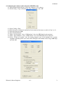
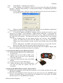
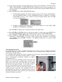
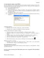
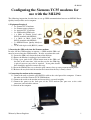
01-09-09 Configuring the Siemens TC35 modems for use with the MI2292 The following instruction describe how to set up GSM communication between an MI2292 Power Quality Analyser Plus and a computer 1. Equipment Required o 2 x Siemens TC35 modems o 2 x Siemens power adaptors o 2 x Aerial for TC 35 modem o 2 x GSM enabled SIM cards o 1 x Male to Female Serial cable (RS232 standard with MI2292) o 1 x Male to Male Serial Cable (RS232 standard with MI2292) o 1 x MI2292 Power Quality Analyser Plus o 1 x PC with 9 pin serial (RS232) connection 2. Inserting the SIM cards into the Siemens modems In order for the GSM modems to operate, a GSM enabled SIM card must be inserted into the GSM modems. In order to perform this task: 2.1.Locate the SIM card slot on the front of the modem. 2.2.Ensure the Modem is unplugged and switched off. 2.3.Using a pen, push in the yellow button next to the SIM card slot and, at the same time, slide out the tray for the SIM chip (a pair of tweezers may also be required. At no point should force should be applied to remove the tray). 2.4.Insert the SIM into the tray so that the gold contacts face up, away from the black plastic. 2.5.Reinsert the tray back into the modem and ensure that the tray is firmly closed. 3. Connecting the modem to the computer 3.1.Connect the male to female serial (RS232) cable to the serial port of the computer. Connect the other end of the Siemens TC35 GSM modem. 3.2.Connect the aerial to the modem and ensure this is screwed in tightly 3.3.Connect the power to the back port of the TC35 modem (the port next to the serial connector) and switch the unit on. 3.4.Switch on the computer Written by Darren Bagshaw v1.1 1 01-09-09 4. Configuring the software and testing the GSM SIM cards. 4.1.load the PowerLink software (ensure the software is v5 or above). 4.2.Click Config -> Type of Instrument, select “PQA plus” and “OK” 4.3.Select Config -> Port 4.4.Select the port on which the modem has been connected (in most cases this is Com 1 or 2) 4.5.Select the baud rate 9600. 4.6.Click “Enable Modem” 4.7.Under “Local modem” select “GSM modem” (leave the PIN blank for the moment) 4.8.Under “Target Modem” select “GSM modem” (leave the PIN blank for the moment) 4.9.In the “Target tel. number” box, for testing purposes type in the number for a nearby telephone or mobile phone (later, this will be changed to the number of the Target SIM chip) and click OK. Written by Darren Bagshaw v1.1 2 01-09-09 4.10. Click Modem -> configure target modem 4.11. Click Configure, If everything is correct, the message box will display the following messages – Baudrate Autosearching -> sending modem settings -> Configuration procedure finished successfully o If error 1602 occurs, either the wrong com port has been selected or the modem is not switched on. Recheck these settings and try again. 4.12. When the configuration has completed successfully, close the Modem configuration window down using the cross in the top right of the window. 4.13. To check the Modem and SIM are working correctly, position the aerial in a good signal area (see chapter 7) Select Modem -> Make modem connection. At this point, the telephone/mobile phone selected in point 9. should start to ring. Hang up immediately and the connection will terminate. The modem has now been configured and is now working correctly. o If the telephone does not start ringing and the error message “NO CARRIER” appears, the SIM chip inserted into the Modem does not have GSM enabled. Contact your Service provider to make sure this is the default service for your SIM card. o If error 1603 occurs, the SIM is not inserted correctly or is not being detected. Remove the SIM, clean the metal pads with your thumb and try again 4.14. Disconnect the modem and connect the other modem to the computer. Repeat steps 10 to 13 to configure the modem and ensure it is working. 5. Connecting the Modem to the MI2292 instrument 5.1. Ensure both the MI2292 and the GSM modem are turned off. 5.2. Connect one end of the Male to Male serial (RS232) cable to the port on the right hand side of the instrument 5.3. Connect the other end of the cable to the GSM modem. 5.4. Connect the Aerial to the GSM modem 5.5. Connect the Power cable to the GSM modem and turn on both the modem and the instrument. 6. Setting up the MI2292 Power Quality Analyser PLUS 6.1.Switch on the instrument, ensure that the instrument is not recording and then turn the right hand dial to CONFIG 6.2.From the menu, highlight in black using the up and down arrow keys the SYSTEM option and press the Enter button (a password may be prompted for at this point, for default passwords, please see the MI2292 user manual). Written by Darren Bagshaw v1.1 3 01-09-09 6.3.A sub menu will appear and depending on the settings of the instrument, will either display GSM / SMS PARAM. or SER. PORT RATE, (changing between these two options can easily be performed by highlighting the option in black and pressing the SELECT button on the instrument). 6.4.Press ENTER on the GSM / SMS PARAM. option. a. If information regarding the memory status is required to be sent to a mobile phone, press the SELECT button to set the GSM/SMS parameters to Enabled >> Disable. Under DEST, use the and arrows to enter the mobile number where the SMS messages should be sent. b. If SMS messaging is not required, use the select button to set the GSM / SMS PARAM. to DISABLED >> ENABLE. Press ENTER to confirm your selection and return to the main menu. 6.5.Press ENTER on SYSTEM again (as described in point 2.) and this time, press SELECT on the GSM / SMS PARAM. option, this should change the option to SER. PORT RATE. 6.6.Press ENTER on SER.PORT RATE to display the baud rate (the speed and which the instrument is communicating). Using the and arrows of the instrument, set this Baud rate to 9600 and press ENTER to confirm. The MI2292 should now be set up for GSM communication. 7. Positioning the Aerials The positioning of the aerial is extremely important for creating a fast and reliable connection between the analyser and the computer. The aerials come as standard with a magnetic base for connecting to metallic objects. It is extremely important that the aerial is positioned away from any strong magnetic fields which can be emitted by such things including motors, exposed wires, electromagnets, televisions, monitors or exposed distribution boards. In order to assess the positioning of the aerial, place the SIM of the modem into a mobile phone and place the phone next to the aerial. This will allow you to analyse and measure the signal strength. If the signal strength is low, the aerial should be moved to a better location. It should always be kept in mind that people will be walking past the aerial and that machinery will be in operation while the analyser is connected to the system so the trailing lead should, where possible be fixed in position and kept as hidden as possible. Written by Darren Bagshaw v1.1 4 01-09-09 8. Connecting the Computer to the MI2292. Once the modems have been checked, connected to the computer and the instrument and the aerials have been positioned correctly, the GSM connection can be tested. Ensure that all the equipment is switched on and connected together correctly. 8.1. Open the PowerLink software. 8.2. Click Config -> Port 8.3. Delete the number in the “Target tel. number” box and enter the telephone number attributable to the SIM in the modem connected to the MI2292 Power Quality Analyser Plus and click OK 8.4. Click Modem -> Make modem connection 8.5. A window will open and if everything is set up correctly, the following window will be displayed: 9. Using the software • Recording can be started by clicking the ! (remote start) button • Recording can be stopped by clicking the X (remote stop) button As long as the instrument has stopped recording: • Instrument settings can be read by clicking File -> Instrument settings -> Read • Instrument settings can be checked and adjusted by clicking File -> Instrument settings -> Details • Instrument signals can be adjusted by clicking File -> Instrument settings -> Details -> … • Instrument settings can be sent by clicking File -> Instrument settings -> Send • Data can be downloaded by clicking File -> Download data • The instrument memory can be cleared by clicking the Clear memory button While the instrument is recording • Recordings can be analysed by clicking the Data -> Direct Link (a very good quality connection for this setting. See “Positioning the Aerials”). 10. Terminating the Connection Terminating the connection between the instrument and the computer by selecting Modem -> Hang up modem connection For more details on setting up the GSM modem, please refer to Appendix VII of the MI2292 user manual. Written by Darren Bagshaw v1.1 5