1
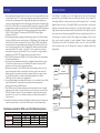
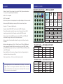
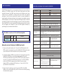
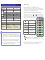
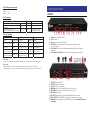
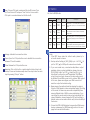
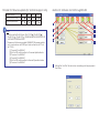
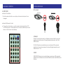
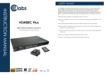
CE labs can support many areas of your audio and video
distribution needs.
• Digital Signage software and Media Players
• HD Matrix Switchers
• RF amplifiers
• HDMI and Component HD distribution amplifiers
• CAT 5 Signal Extenders
• VGA Extenders and Splitters
• and cables of all types.
See our full product line at www.celabs.net
WARRANTY
Cable Electronics, Inc. warrants this product to be free from defects in
material and workmanship, under normal use and service, for a period of
one year from the purchase by the original purchaser. If this product is
defective or malfunctions, Cable Electronics will replace or repair this unit
(at their option) within a reasonable time. No expressed or implied warranty
is made for any defects caused by immersion or exposure to liquids, abuse,
neglect, improper operation of unit, excess wear and tear and defects
resulting from unauthorized disassembly and or modification.
3209 Wood Drive
Garland, TX 75041
Phone: (469) 429-9200
Toll free: (800) 767-6189
Fax: (469) 429-9205
www.celabs.net
Document: HSW44C_manual.pdf
INSTRUCTION MANUAL
We manufacture:
HSW44C
4x4 HDMI over CAT5 Matrix
with IR Pass-through
7..1 CH
AUDI
UDOO
SAFETEY & NOTICE
The HSW44C 4x4 HDMI over CAT5 Matrix with IR Pass-through has been
tested for conformance to safety regulations and requirements, and
has been certified for international use. However, like all electronic
equipment, the HSW44C should be used with care. Please read and
follow the safety instructions to protect yourself from possible injury
and to minimize the risk of damage to the unit.
• Follow all instructions and warnings marked on this unit.
• Do not attempt to service this unit yourself, except where
explained in this manual.
• Provide proper ventilation and air circulation and do not
use near water.
• Keep objects that might damage the device and assure
that the placement of this unit is on a stable surface.
• Use only the power adapter and power cords and
connection cables designed for this unit.
• Do not use liquid or aerosol cleaners to clean this unit.
• Always unplug the power to the device before cleaning.
NOTICE
INTRODUCTION
1. When adjusting the signal level on the receiver unit, please dial the rotary
control switch from 7 to 0 and stop turning the rotary switch whenever the
audio/video is playing normally. Inappropriate signal level setting may
cause overpowering issue that would shorten the product life significantly!
2. If the DVI or HDMI device requires the EDID information, please use EDID
Reader/Writer to retrieve and provide DVI or HDMI display EDID information.
3. All HDMI over CAT5 transmission distances are measured using Belden
1583A CAT5e 125MHz UTP cable and ASTRODESIGN Video Signal
Generator VG-859C.
4. The transmission length is largely affected by the type of Cat-5/5e/6 cables,
the type of HDMI sources, and the type of HDMI display. The testing result
shows solid UTP cables (usually in the form of 300m [1,000ft] bulk cables)
can transmit a lot longer signals than stranded UTP cables (usually in the
form of fixed length patch cords). Shielded STP cables are better suited
than unshielded UTP cables. A solid UTP Cat-5e cable shows longer
transmission range than stranded STP Cat-6 cable. For long extension
applications, solid UTP/STP cables are the only viable choice.
5. EIA/TIA-568-B termination (T568B) for Cat-5/5e/6 cables is recommended
for better performance.
6. To reduce the interference among the unshielded twisted pairs of wires
in Cat-5/5e/6 cable, one can use shielded STP cables to improve EMI
problems, which is worsen in long transmission.
7. Because the quality of the CAT5/6 cables has the major effect on how
long the transmission limit can achieve and how good is the received
picture quality, the actual transmission range is subject to one’s choice
of Cat-5/5e/6 cables. For desired resolutions greater than 1080i or
1280x1024, a Cat-6 cable is recommended.
8. If your HDMI display has multiple HDMI inputs, it is found that the first HDMI
input [HDMI input #1] generally can produce better transmission
performance among all HDMI inputs.
9. The HSMR has been tested extensively and found that it doesn’t require
external power supply. If in rare situation you find it cannot work with the
HSW44C, please use any +5V power adapter to plug in the power jack
and see if it can work. If not, please contact your technical support for
further service.
10. Additional IR remote controls and IR blaster cables can be purchased as
optional accessories to control the HDMI sources located separately.
The HSW44C 4x4 HDMI over CAT5 Matrix Switch with IR Pass-through
provides the most flexible and cost effective solution in the market to
route high definition video sources plus multi-channel (up to 7.1-channel)
digital audio from any of the eight HDMI source devices to the remote
displays at the same time. Through low cost Cat-5/5e/6 cables, not only
high quality video and audio can be transmitted to the display sites, but
also users can switch among eight HDMI sources using the push button on
the receiver or remote control. With single power design at the source
site, each remote module is easily installed without power supply.
Furthermore, the built-in IR extension allows users to control the HDMI
source devices such as the Blu-ray Disc player or satellite receiver at
display site!
4x HDMI Source
Two LAN cables
PS3
HDMI cable
HSMR
IR receiver
Blu- ray Disc Player
IR controller
HSMR
TiVo
HSMR
HDMI Camera
Performance Guide for HDMI over LAN Cable Transmission
Performance rating
Wiring
Solid
Stranded
Shielding
Unshielded (UTP)
Type of LAN cable
CAT5
CAT5e
CAT6
Shielded (STP)
Unshielded (UTP)
Shielded (STP)
Termination
Please use EIA/TIA-568-B termination (T568B) at any time
4x HDTV
HSMR
FEATURES
• State-of-the-art Silicon Image (Founder of HDMI) chipset embedded
for upmost compatibility and reliability
IR DIRECT CODES
Default Custom Code — IR2 Code: 00 FF
0x0A
0x0C
POWER
0x02
SOURCE SEL. 1
SOURCE SEL. 2
SOURCE SEL 3
SOURCE SEL. 4
F1
0x57
F2
0x58
F3
0x59
F4
0x06
• HDMI 1.3c compliant
• HDCP compliant
0x54
• Allows any source to be displayed on multiple displays at the same time
—
Function
0x17
• Allows any HDMI display to view any HDMI source at any time
• Supports 7.1 channel digital audio
0x55
0x56
Output Port 1
• Supports default HDMI EDID and learns the EDID of displays
Input 1- 0x18
Input 2 - 0x5B Input 3 - 0x19
Input 1 - 0x1B
Input 2 - 0x5A Input 3- 0x1A
• Allows control of local HDMI sources such as DVD and TiVo® by IR
extender through control path at remote receiver
Input 1 - 0x0E
Input 2 - 0x0D
• Allows control of main matrix center through control line at remote
receiver
Input 1 - 0x1C
• Easy installation with rack-mounting and wall-mounting designs for
master and receiver respectively
• Fast response time – 2~5 seconds for channel switch
Input 4 - 0x07
Output Po2
• The matrix master can switch every output channels to any HDMI
inputs by push-in button, IR remote control, or RS-232 control
• Extends video signal up to 35m (115 feet) over CAT5e at 1080p and
likely longer with better HDMI source device (such as PS3®), better
grade HDMI display (such as Sony X-series HDTV®), and better quality
solid CAT6 cable
0x01
Input 4 - 0x04
Output Po3
Input 3 - 0x12 Input 4 - 0x05
Output Po4
Input 2 - 0x1D
Custom Code — IR3 Code: 0x12 0x21
Output 1
Output 2
Output 3
Output 4
Source 1
0xA1
0xB1
0xC1
0xD1
Source 2
0xA2
0xB2
0xC2
0xD2
Source 3
0xA3
0xB3
0xC3
0xD3
Source 4
0xA4
0xB4
0xC4
0xD4
Custom Code — IR4 Code: 0x13 0x31
Output 1
Output 2
Output 3
Output 4
The length depends on the characteristics and quality of the cables.
Source 1
0xAE
0xBE
0xCE
0xDE
Higher resolutions and longer transmission distances require low skew
Source 2
0xAD
0xBD
0xCD
0xDD
cables (<25ns/100m) for best performance. Unshielded CAT6 with metal
Source 3
0xAC
0xBC
0xCC
0xDC
RJ-45 connectors is recommended.
Source 4
0xAB
0xBB
0xCB
0xDB
Input 3 - 0x1F
Input 4 - 0x1E
EDID LEARNING
SPECIFICATIONS & PACKAGE CONTENTS
The EDID learning function is only necessary whenever you encounter any
display on the HDMI output port that cannot play audio and video
properly. Because the HDMI source devices and displays may have
various level of capability in playing audio and video, the general
principle is that the source device will output the lowest standards in
audio format and video resolutions to be commonly acceptable among
all HDMI displays. In this case, a 720p stereo HDMI signal output would be
probably the safest choice. Nevertheless, the user can force the matrix to
learn the EDID of the lowest capable HDMI display among others to make
sure all displays are capable to play the HDMI signals normally by
performing the procedures stated below.
Model Name
HSW44C
Technical
Role of usage
HSW44C
HSMR
4x4 true matrix / Transmitter [TX]
Receiver [RX]
HDMI compliance
HDMI 1.3c
HDCP compliance
Yes
Video bandwidth
Single-link 225MHz [6.75Gbps]
Video support
480i / 480p / 720p / 1080i / 1080p60 12-bit color
Audio support
Surround sound (up to 7.1ch) or stereo digital audio
HDMI over CAT5
transmission range
Full HD (1080p) – 35m (115ft) [CAT5e] / 40m (130ft) [CAT6]
HD (720p/1080i) – 50m (165ft) [CAT5e] / 55m (180ft) [CAT6]
HDMI equalization
N/A
Input TMDS signal
Input DDC signal
SW1-SW4 Pin-1 must be set “ON” for EDID Learning Mode
DIP Switch Position
Pin-1
ON [ ]
Video
Bypass
Audio
Stereo
Description
EDID Learning – for learning EDID from the
receiver
Manually connect displays to HDMI input ports
1. Power up the matrix master unit. Connect the HDMI display that its
EDID needs to be learned to any of the HDMI INPU1-INPU4 port where
your source device has trouble to show the picture normally.
2. To learn the display’s EDID for source device connected to respective
HDMI INPU1-INPUT8 port, pull both pins of respective DIP switch
SW1-SW4 up-and-down to stay at ON[ ]-ON[ ] and wait for about 5
seconds to complete the EDID learning process. You DON’T NEED to
pull up the DIP switch again unless you want to learn another
display’s EDID by pulling both DIP switch pin-1 & pin-2 of SW1-SW4
up-and-down one more time.
3. Repeat step1 & step2 if you want to learn the EDID of this HDMI
display on any other HDMI input ports that have same trouble playing
the audio/video properly.
8-level digital rotary control
1.2 Volts [peak-to-peak]
5 Volts [peak-to-peak TTL]
ESD protection
[1] Human body model — ±19kV [air-gap discharge] & ±12kV [contact
discharge]
[2] Core chipset — ±8kV
PCB stack-up
4-layer board [impendence control — differential 100Ω single 50Ω]
Input
4x HDMI
1x RS-232
1x RJ-45 [HDMI signal]
1x RJ-45 [Channel control]
1x IR socket for IR receiver
Output
4x RJ-45 [HDMI signal]
4x RJ-45 [Channel control]
5x IR socket for IR blaster
1x HDMI
HDMI Input selection
Push button / IR remote control /
RS-232
Push button / IR remote control
HDMI source control
Controllable via IR pass-through from IR receiver at HSMR to IR blaster at
HSW44C
IR remote control
Electro-optical characteristics: τ = 25° / Carrier frequency: 36-40kHz
HDMI connector
Type A [19-pin female]
RJ-45 connector
WE/SS 8P8C with 2 LED indicators
RS-232 connector
USB connector3
3.5mm connector
DIP switch
DE-9 [9-pin D-sub female]
Standard type-B [square shape]
Earphone jack for IR receiver
Earphone jack for IR blaster
[IR RECEIVER] Receives IR commands
[IR Main] IR control on all source
from any IR remote control
devices
[IR PASS-THROUGH1~8] IR control
on individual source device
[SW1~SW4] 2-pin for EDID & audio/video settings
[SW Main] 4-pin for operation & firmware update
DISPLAY SIDE
SPECIFICATIONS & PACKAGE CONTENTS
Mechanical
HSW44C
HSMR
Housing
Metal enclosure
Model
Dimensions
(L x W x H) Package
Carton
Weight
Model
440 x 290 x 44mm
[1’5” x 11.4” x 1.7”]
85 x 90 x 25mm
[3.3” x 3.5” x 1”]
530 x 400 x130mm [1’9” x 1’4” x 5”]
280 x 550 x 420mm [11” x 1’10” x 1’5”]
3250g [7.2 lbs]
180g [6.3oz]
Package
Fixedness
Power supply
Power consumption
Operati on temperature
Storage temperature
Relative humidity
Package Contents
7.1 kg [15.6 lbs]
1U rack-mount with ears
Wall-mount with screws
AC Power 100-240V
Not necessarily required1
Method A: Push button for switching input channels
Press the INPUT SELECT push button to switch the input source on the respective output
port connected to the matrix receiver in sequential order. The selected input source will
be displayed on the seven segment display of INPUT CHANNEL.
Method B1: IR remote control for switching input channels
Please decide which input channel to be selected by pressing Source Selection 1 to
button to enter IR control
Source Selection 4. Or you can use left — and right
mode and select the input channel in ascending and descending order respectively.
The setting will be effective in a couple of seconds.
1.5 Watt [max] (provided by
HSW44C)
60 Watts [max]
0~40°C [32~104°F]
Switch input port in descending
order*
—
-20~60°C [-4~140°F]
20~90% RH [no condensation]
1x HSW44C
1x IR blaster2
2x 1U rack mounting-ear
1x IR remote control2
1x Instruction manual
4x HSMR
4x IR receiver
8x Wall-mounting screws
1x 5V 6A power supply unit
1. The HSMR has been tested extensively and found that it doesn’t require
external power supply. If in rare situation you find it cannot work with the
HSW44C, please use any +5V power supply unit to plug in the power jack
and see if it can work. If not, please contact our technical support for further
service.
2. Additional IR remote control and IR blaster cable can be purchased as
optional accessories to control the HDMI sources located separately.
3. USB or RS-232 control must be connected either one at a time. Connecting
both types of cables may cause command confusion.
Switch input port in ascending
order*
SOURCE SELECTION 1
Switch the display channel at the
remote site to input port 1
SOURCE SELECTION 2
Switch the display channel at the
remote site to input port 2
SOURCE SELECTION 3
Switch the display channel at the
remote site to input port 3
SOURCE SELECTION 4
Switch the display channel at the
remote site to input port 4
Note
Right (
) button to switch input source in ascending order (1, 2, 3, 4, 1, 2, ......)
Left ( — ) button to switch input source in descending order (1, 4, 3, 2, 1, 4, ......)
Method B2: IR remote control for controlling the HDMI sources
Users can use the corresponding IR remote to control the HDMI source.
RS-232 transmission Format
PANEL DESCRIPTIONS
Baud rate: 9600
Data bit: 8
Parity:
None
HSW44C
Set Command
Command Code
Data
0x08 0x4d 0x41 0x51 0x44 0x05
*0x01~0xff
0x0c 0x4d 0x41 0x51 0x44
Device_Id 0x02 port1 port2 port3 port4
Check Sum
0x31~0x2f
Response
ACK
0xaa
0x0c+…+port4 0xaa
Description
SET
Set HSW44C’s device ID
Set HSW44C’s source
mapping of output port
6
Status Command
Command Code
Response
Data
Check Sum
Get Status
0x05 0x4d 0x4f 0x44
0xe5
0xaa 0x06 0x4d 0x41
0x51 0x44
0x07 0x4d 0x41 0x53
0x43
0x57 0x04
0x08 0x4d 0x41 0x51
0x2e~0x2c
0x44 *0x01~0xFF 0x01
0x08 0x4d 0x41 0x51
0x30~0x2e
0x44 *0x01~0xFF 0x04
0xaa 0x3 0x01~0xff
0xaa 0x06 port1
port2 port3 port4
0xaa 0x08 0x56 0x33
0x2e 0x30 0x31 0x61
Description
Check Sum
0x29
0x04~0x02
0x06 +
port1~port4
0x81
Status
Get device type
Get device ID
Get source mapping
of output port
Software version
5
4
6
5
4
6
5
4
6
5
4
3
2
1
1.
2.
3.
4.
Power: Power indicator LED
IR: IR receiver
Input: Input source indicator LED
HP1–HP4: Hot-plug connection status indicator LED for each
output channel
5. Port1–Port4: Input source channels mapping LED for each output
channel
6. Port1 Select–Port4 Select: Push button for selecting input channel
Check sum:
Check sum = (Data value sum)%256 The check sum of response is not included 0xaa.
0x01 ~ 0xFF:
This data is device ID. The Device ID saved in the device, if the device ID of the
controlled device is 0xff , the device will ignore its own ID and carry out the commands.
7 8
9 10
11 13 12 13
11 13
13
14
15
7. ON–OFF: Power ON/OFF
8. RS-232: RS-232 control port
9. +5V DC: 5V DC power jack
10. SW Main: DIP switches [see DIP Switch section in p.8]
11. SW1–SW4: DIP switch [see DIP Switch section in p.7]
12. IN1–IN4: HDMI inputs
13. IR1–IR4: IR extender jacks for individual HDMI source control
14. OUT1–OUT4: RJ-45 TMDS/DDC outputs for each output channel
15. IR Main: IR extender jack for all HDMI source control [default socket for
IR emitter]
HSMR
1
2
3
7
Fast Select: Provide the fast setup be tween inputs and outputs
of the matrix. “Channel 1” makes all outputs see input-1, same
for the remaining buttons.
8
Output Channel Setup: Click on this button, a quick selection
table of inputs will show up. Users can therefore easily select
4
8
5
6
7
1. +5V DC: Spare power jack for over 60m transmission when the RX
may need external power to work*.
2. TMDS: Plug in the CAT5 connected to the respective TMDS port
on the HSW44C
3. DDC: Plug in the CAT5 connected to the respective DDC port on
the HSW44C
4. INPUT CHANNEL: Display the current showing HDMI source
channel
5. INPUT SELECT: Push button for switching input source channel in
sequential order
6. Signal Level 0-7: Adjust the 8-level equalization control for HDMI
signals. 0 = strongest to 7 = weakest. It is recommended to switch
from 7 to 0 to find the optimal visual experience.
7. HDMI Output: Connect to HDTV with a HDMI cable
8. IR RECEIVER: Plug in IR receiver
The HSMR has been tested extensively and found that it doesn’t
require external power supply. If in rare situation you find it
cannot work with the HSW44C, please use any +5V power
adapter to plug in the power jack and see if it can work. If not,
please contact our technical support for further service.
the input video for each output.
2
Scan: Choose COM port number and Device ID for scan. Then
tick “Scan Device ID”and press “Scan” button to know which
COM port is connected based on this Device ID.
DIP SWITCH
SW1-SW4 for EDID/Audio
DIP Switch Position
3
Linkage: Indicate the connection status.
4
Open: Open the COM port after scan to establish the connection
between PC and the matrix.
5
Close: Release the COM port after scan.
6
Mapping: Click on this button, a quick selection table of inputs will
show up. Users can therefore easily select the output video for each
input by pressing “Output” button.
Video
Audio
OFF [ ]
Up to
1080p
Surround1
OFF [ ]
ON [ ]
Up to
1080p
Stereo
Safe Mode3 – Enforce the system output at 1080p
video and stereo audio for basic compatibility
among HDTVs
ON [ ]
OFF [ ]
Bypass4
Bypass4
EDID Learning Mode5 – for learning EDID from the
display while playing any received HDMI audio
format
ON [ ]
ON [ ]
Bypass
Stereo
EDID Learning & Stereo Mode5 – for learning EDID
from the display while enforcing stereo output if
any HDTV cannot play surround sound normally
Pin 1
Pin 2
OFF [ ]
Description
Default Mode2 – Up to 1080p video & surround
sound audio output up to 7.1ch DTS-HD & Dolby
TrueHD
Note:
1. If the HDTV shows video but without audio, please try to
set audio mode to stereo.
2. Factory default setting of [SW1]-[SW4] is pin 1 at OFF ( ) &
pin 2 at OFF ( ) for 1080p with surround sound audio.
3. If you encounter any unsolved audio/video output
problem during system installation, please turn any
[SW1]-[SW4] to pin 1 at OFF ( ) & pin 2 at ON ( ) for
safe mode to enforce the most compatible 720p stereo
output for system check. However, the safe mode cannot
be initiated if your HDMI source is set to enforce 1080p output.
In this case, please reconfigure your HDMI source to all
resolution output for troubleshooting.
4. Bypass means the matrix will maintain playing the original
format of HDMI signals in video and perhaps audio. By setting
at this mode, the users may encounter compatibility issue
among different kinds of HDMI sources and displays. If you
cannot get the audio and/or video output normally at the
system installation, please change the DIP switch setting to
default mode or even safe mode to verify the functionality of
the device.
5. To learn the EDID of HDMI display for respective HDMI source
devices, please see the [EDID Learning] section in the next
page for more detail information.
SW Main for firmware update (for technical support only)
DIP Switch Position
Pin 1
Pin 2
Pin 3
Pin 4
Normal Operation Mode6
OFF [ ]
OFF [ ]
ON [ ]
OFF [ ]
Firmware Update Mode7
ON [ ]
ON [ ]
OFF [ ]
OFF [ ]
Method C: Software Control through RS-232
1
7
Note
6. Factory default for SW Main: Pin#1-OFF [ ], Pin#2-OFF[ ],
Pin#3-ON [ ], Pin#4-OFF[ ]. PLEASE MAINTAIN THIS SETTING AT
ANYTIME FOR REGULAR USE!
7. Sequence for firmware update WARNING! [Firmware update
only can be done via RS-232 port and connection to PC set
at COM1)
[1] Power off the HSW44C.
[2] Set the DIP switch position to Firmware Update Mode.
[3] Power on the HSW44C.
[4] Power off the HSW44C.
[5] Set the DIP switch position to Normal Operation Mode.
[6] Power on the HSW44C.
2
3
4
1
6
5
8
Setting: Set the ID of this device for cascading or other purposes in
the future.
CHANNEL CONTROL
MATRIX SIDE
IR PASS-THROUGH
IR Sockets
IR Blaster
Method A: Push Button
IR Receiver
1. Push the red switch button on output port to select which port to be
changed.
Method B: IR Remote Control
a. Choose the output port you want to make channel switch from OUT1
to OUT4 then press 1-4 channel button to choose the HDMI input source
shown on the chosen output display.
HSW44C
IR Main: The default location for IR blaster to transmit all IR command
signals received from any of the eight remote receivers to all of the
HDMI sources.
IR1– IR4: IR blaster connected here can only transmit IR command
signals from the remote receivers that are setting at respective input
channel from 1 to 4.
HSMR
IR RECEIVER: IR receiver connected here can receive all IR command
signals from the IR remote controls of HSW44C and all other HDMI source
devices.
HARDWARE INSTALLATION
Definition of IR Earphone Jack
IR Blaster
IR Receiver
The IR extension cables are standard market configuration. You can
buy from CE labs if necessary for replacement use.
Suitable
1. Connect all sources to HDMI Inputs on the 4x4 HDMI over CAT5 matrix
master HSW44C
2. Connect each DDC output port on the HSW44C to respective DDC
input on the remote receiver HSMR
3. Connect each TMDS output port on the HSW44C to respective TMDS
input on the remote receiver HSMR
4. Connect IR blaster to the IR MAIN jack of HSW44C and direct the IR
blaster to the built-in IR receiver of the sources
5. Connect the 5V 6A DC power supply unit to the HSW44C
6. Power on all HDMI sources
7. Power on the HSW44C
HSMR as receiver
Supported IR Data Format
Data Format
NEC
RC5
TOSHIBA MICOM CODE
GRUNDIG CODE
SONY 12 BIT CODE
SONY 15 BIT CODE
SONY 20 BIT CODE
RCA CODE
RCM CODE
MATSUSHITA CODE
MITSUBISHI CODE
ZENITH CODE
JVC CODE
M50560-001P
MN6125H
MN6125L
MN6014_C5D7
MN6014-C6D6
MC14457P
LC7464(AHEA)
GEMINI_CM
HSW44C as master
Not Recommended
1. Connect each HDMI output to HDMI displays
2. Connect each DDC output port on the HSW44C to respective DDC
port on the HSMR
3. Connect each TMDS output port on the HSW44C to respective TMDS
input on the remote receiver HSMR
4. Connect IR receiver and place the IR receiver at the appropriate
position that can receive the IR command signals sent from the users
5. Dial the 8-level rotary control switch to adjust the HDMI signal level
until the picture and sound are clear