1
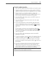
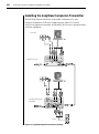
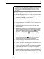
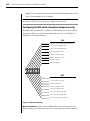
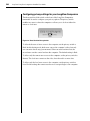
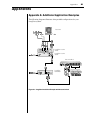
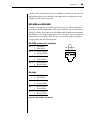
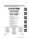
LongView ®
LongView Companion®
Installer/User Guide
INSTRUCTIONS
This symbol is intended to alert the user to the presence of important
operating and maintenance (servicing) instructions in the literature
accompanying the appliance.
DANGEROUS VOLTAGE
This symbol is intended to alert the user to the presence of uninsulated
dangerous voltage within the product’s enclosure that may be of sufficient
magnitude to constitute a risk of electric shock to persons.
POWER ON
This symbol indicates the principal on/off switch is in the on position.
POWER OFF
This symbol indicates the principal on/off switch is in the off position.
PROTECTIVE GROUNDING TERMINAL
This symbol indicates a terminal which must be connected to earth ground
prior to making any other connections to the equipment.
LongView ®
LongView Companion®
Installer/User Guide
Avocent, the Avocent logo and The Power of Being There are
trademarks of Avocent Corporation. LongView, Companion,
AutoTuning and Cybex are registered trademarks of Cybex
Computer Products Corporation. All other marks are the property of their respective owners.
© 2002 Avocent Corporation. All rights reserved.
USA Notification
Warning: Changes or modifications to this unit not expressly approved by the party
responsible for compliance could void the user's authority to operate the equipment.
Note: This equipment has been tested and found to comply with the limits for a Class
A digital device, pursuant to Part 15 of the FCC Rules. These limits are designed
to provide reasonable protection against harmful interference when the equipment is
operated in a commercial environment. This equipment generates, uses and can radiate
radio frequency energy and, if not installed and used in accordance with the instruction
manual, may cause harmful interference to radio communications. Operation of this
equipment in a residential area is likely to cause harmful interference in which case the
user will be required to correct the interference at his own expense.
Canadian Notification
This digital apparatus does not exceed the Class A limits for radio noise emissions
from digital apparatus set out in the Radio Interference Regulations of the Canadian
Department of Communications.
Le présent appareil numérique n’émet pas de bruits radioélectriques dépassant les
limites applicables aux appareils numériques de la classe A prescrites dans le Règlement
sur le brouillage radioélectrique édicté par le Ministère des Communications du Canada.
Japanese Notification
Agency Approvals
UL 1950, CSA C22. 2 No. 950, EN60950, IEC 60950
FCC part 15A, EN55022, EN55024
Table of Contents
Chapter 1: Product Overview
Features and Benefits . . . . . . . . . . . . . . . . . . . . . . . . 3
Compatibility . . . . . . . . . . . . . . . . . . . . . . . . . . . . . . . 5
Safety Precautions . . . . . . . . . . . . . . . . . . . . . . . . . . . 6
Chapter 2: Installation
Getting Started . . . . . . . . . . . . . . . . . . . . . . . . . . . . . 9
Installing the LongView Transmitter. . . . . . . . . . . 10
Installing the LongView
Companion Transmitter . . . . . . . . . . . . . . . . . . . 12
Installing the Receiver . . . . . . . . . . . . . . . . . . . . . . . 17
Appendices
Appendix A: Additional Application Examples . . 21
Appendix B: Technical Specifications . . . . . . . . . . 24
Appendix C: Video Resolution . . . . . . . . . . . . . . . . 25
Appendix D: Technical Support . . . . . . . . . . . . . . . 26
Appendix E: Troubleshooting . . . . . . . . . . . . . . . . 27
Appendix F: Advanced Questions . . . . . . . . . . . . . 29
Appendix G: Category 5 Cable. . . . . . . . . . . . . . . . 32
1
Product Overview
Contents
Features and Benefits . . . . . . . . . . . . . . . . . . . . . . . . . 3
Compatibility . . . . . . . . . . . . . . . . . . . . . . . . . . . . . . . 5
Safety Precautions . . . . . . . . . . . . . . . . . . . . . . . . . . . 6
Chapter 1: Product Overview
3
Chapter 1: Product Overview
Features and Benefits
The LongView and LongView Companion Keyboard/Video/Mouse (KVM)
extenders allow you to extend the distance between your computer and your
VGA monitor, PS/2 keyboard, PS/2 mouse, stereo speakers, microphone and
serial port device. All of these signals can be extended up to 500 feet (152 meters)
using a single inexpensive and commonly available Category 5 Unshielded
Twisted Pair (UTP) cable - the type used in most Local Area Networks.
LongView consists of a transmitter placed near the computer and a receiver
placed near the remote user’s monitor. Both the transmitter and receiver are
powered using wall-mount power supplies. The LongView Companion allows
for a second workstation to be located near the computer for convenient
system maintenance. Versions are available with and without audio
capabilities (speakers and microphone).
LongView and LongView Companion are simple to install. Avocent’s
AutoTuning capability provides automatic compensation for different cable
lengths, video resolutions and serial COM port data rates.
Access sharing
The LongView Companion models allow two users to share the use of a single
computer. Both users can see the computer’s video, but only one can enter
data at any given moment. A local user is next to the connected computer
while an extended user can be up to 500 feet away.
Space saving
LongView and LongView Companion let you keep your peripherals where you
need them and locate your system unit in a climate-controlled, dust/chemicalfree setting. Moving your system unit away from your desk and work area
frees up valuable space for other uses.
Easy installation
There are no jumpers to install or switches to set for cable length or COM port
data rates. No software installation or configuration of any kind is required.
The LongView and LongView Companion connect to your computer just like
other peripherals.
High resolution video
The LongView and LongView Companion support SVGA resolutions up to
1600x1200. See Appendix C for further details.
4
LongView/LongView Companion Installer/User Guide
Serial port
The LongView and LongView Companion can extend a computer’s serial COM
port to the desktop for use with devices such as touchscreens, modems or serial
printers. Both models auto-configure for any COM data rate up to 19.2 Kbps.
Audio capabilities
Extend your computer’s speaker output and microphone input to a remote
workstation. Fully bidirectional (full-duplex) stereo audio is supported.
Versions of the LongView product family without audio capabilities are also
available, if desired.
Data center flexibility
For access to multiple computers, use your LongView or LongView
Companion in conjunction with an Avocent KVM switch. By using these
products in combination, you can control and operate all of your data center’s
servers either locally or remotely from the computer lab down the hall.
AutoBoot technology
The AutoBoot feature in the LongView and LongView Companion prevents
attached computers from locking up when there is no keyboard or mouse
attached during boot-up. This same feature allows a user to unplug and
reconnect a mouse at the transmitter or receiver end without having to reboot.
Privacy feature
Privacy options in the LongView Companion allow the user to blank the
inactive user’s screen when content sensitive work is in progress.
Security
Protect your system unit, software and sensitive/valuable data from
unauthorized activities or losses. LongView and LongView Companion can
serve effectively as an anti-theft device by allowing you to place the system
unit in a secure area, while providing keyboard, mouse, monitor, audio and
serial device access to those who need it.
FLASH upgradable
The LongView Companion’s FLASH upgrade feature allows you to update
your LongView firmware and keep it current with the latest upgrades
from Avocent. For more information on FLASH upgrading your LongView
Companion, please visit the Avocent web site.
Chapter 1: Product Overview
5
CAT 5 Connection
KVM Connection to Switch
Extended
access user
LongView
receiver
LongView
Companion
Server
Analog user
Figure 1.1: A Typical LongView Configuration
Compatibility
PS/2 peripherals
The LongView requires a PS/2 mouse and keyboard for proper operation. The
LongView offers support for many PS/2 mice including:
•
IBM Scrollpoint
•
Logitech Mouseman Wheel
•
Logitech Trackman Marble Wheel
•
Logitech Trackman Marble FX
•
Kensington 4 Button Mouse
•
Microsoft Explorer Mouse
•
Microsoft IntelliMouse
Other manufacturers' mice may operate with the LongView. If you experience
problems using an untested mouse, contact Avocent Technical Support with
the manufacturer and model number of the mouse.
Other extension products
The Avocent LongView/LongView Companion are not compatible with any
other extension products, including the Cybex LongView/LongView Companion.
6
LongView/LongView Companion Installer/User Guide
Safety Precautions
To avoid potential video and/or keyboard problems when using Avocent
products, please observe the following precautions:
•
If the building has 3-phase AC power, ensure that the computer and
monitor are on the same phase. For best results, they should be on the
same circuit.
•
Use only Avocent-supplied cable to connect computers and KVM
switches. Avocent warranties do not apply to damage resulting from
user-supplied cable.
•
Use only Avocent-supplied power supply.
To avoid potentially fatal shock hazard and possible damage to equipment,
please observe the following precautions:
•
Do not use a 2-wire extension cord in any Avocent product configuration.
•
Test AC outlets at the computer and at the monitor for proper polarity
and grounding.
•
Use only with grounded outlets at both the computer and monitor.
2
Installation
Contents
Getting Started . . . . . . . . . . . . . . . . . . . . . . . . . . . . . . 9
Installing the LongView Transmitter . . . . . . . . . . . 10
Installing the LongView Companion Transmitter . 12
Installing the Receiver . . . . . . . . . . . . . . . . . . . . . . . 17
Chapter 2: Installation
9
Chapter 2: Installation
Getting Started
Before installing your LongView system, refer to the lists below to ensure that
you have all the items that shipped with the LongView as well as all other
items necessary for proper installation.
Supplied with the LongView and LongView Companion
Your LongView or LongView Companion package contains the following items:
•
LongView transmitter or LongView Companion transmitter
•
Avocent CIFCA cable
•
LongView receiver
•
Two LongView power supplies
•
LongView/LongView Companion Installer/User Guide
•
Audio cables (optional)
Needed for installation
•
One Category 5 cable with four UTP cables (purchased separately)
10
LongView/LongView Companion Installer/User Guide
Installing the LongView Transmitter
The following diagram illustrates one possible configuration for your
LongView. Follow the step-by-step procedures To install a LongView
transmitter and Installing the Receiver to properly install your new equipment.
For more installations examples see Appendix A.
Local user
LongView receiver
(front)
LongView receiver
(back)
LongView transmitter
Server
Figure 2.1: LongView Installation Example
Chapter 2: Installation
11
To install a LongView transmitter:
1.
Power down the computer that will be included in your LongView system.
2.
Unplug the peripherals (keyboard, mouse, monitor, speakers with built-in
amplifiers, microphone and serial device if applicable) from your computer.
3.
Prepare locations for your LongView equipment, computer and
peripherals. Place the transmitter near your computer. Place the receiver
near your monitor, keyboard, mouse, speakers and microphone.
4.
Connect the CIFCA cable’s 25-pin connector to the INPUT connector on
the rear of the transmitter.
5.
Connect the CIFCA cable’s 15-pin video connector to the video output
connector on your PC.
6.
If you are using a PS/2 mouse, connect the CIFCA cable’s PS/2 mouse
connector, designated by a mouse icon, into your PC’s PS/2 mouse port.
You may use the transmitter’s female serial COM port (
) to extend
other devices.
-orIf you are using a serial mouse, use a standard serial cable (9 -pin
male to 9 -pin female) to connect the LongView’s female port (
)
to your PC’s serial COM port. Leave the CIFCA cable’s PS/2 mouse
connector unattached.
7.
Connect the CIFCA cable’s remaining 6-pin connector into the PS/2
keyboard port on your PC.
8.
To connect your speakers, connect the speaker or line output port from your
computer to the speaker connector (
) on the rear of the transmitter.
9.
To connect your microphone, connect the microphone or line output
port from your computer to the microphone connector ( ) on the rear of
the transmitter.
10. Connect the circular power plug from the provided wall-mount power
supply into the 24 VDC .5A port on the rear of the transmitter. Next,
connect the power supply into a convenient electrical outlet. Verify that
the power light on the front of the transmitter is lit or blinking.
NOTE: The LongView and attached computer should be powered down before servicing the
unit. Always disconnect the power supply from the wall outlet.
12
LongView/LongView Companion Installer/User Guide
Installing the LongView Companion Transmitter
The following diagram illustrates one possible configuration for your
LongView Companion. Follow the step-by-step procedures To install a
LongView Companion transmitter and Installing the Receiver to properly install
your new equipment.
Local user
LongView receiver
LongView Companion
transmitter
Server
Figure 2.2: LongView Companion Installation Example
Chapter 2: Installation
13
WARNING: To reduce the risk of electric shock or damage to your equipment - Do not disable the power cord grounding plug. The grounding plug is an important safety feature.
- Plug the power cord into a grounded (earthed) outlet that is easily accessible at all times.
- Disconnect the power from the unit by unplugging the power cord from either the electrical
outlet or the unit.
To install a LongView Companion transmitter:
1.
Power down the computer that will be included in your LongView system.
2.
Unplug the peripherals (keyboard, mouse, monitor, speakers, microphone
and serial device if applicable) from your computer.
3.
Prepare locations for your LongView equipment, computer and
peripherals. Place the transmitter near your computer. Place the receiver
near your remote monitor, keyboard, mouse, speakers and microphone.
4.
Connect the CIFCA cable’s 25-pin connector to the INPUT connector on the
rear of the transmitter.
5.
Connect the CIFCA cable’s 15-pin video connector to the video output
connector on your PC.
6.
If both users are using PS/2 mice, connect the CIFCA cable’s PS/2 mouse
connector, designated by a mouse icon, into your PC’s PS/2 mouse port.
You may use the transmitter’s female serial COM port (
) to extend
other devices. To do this, connect a standard serial cable from the
LongView’s female serial COM port (
) to your PC’s serial COM port.
-orIf both users are connecting serial mice to the LongView Companion,
use a standard serial cable (9-pin male to 9-pin female) to connect the
LongView’s lower (female) port (
) to your PC’s serial COM port.
Leave the CIFCA cable’s PS/2 mouse connector unattached.
7.
Connect the CIFCA cable’s remaining 6-pin connector into the PS/2
keyboard port on your PC.
8.
To connect your speakers, connect the speakers or line output port of your
computer to the speaker connector (
) on the rear of the transmitter.
9.
To connect your microphone, connect the microphone or line output port
of your computer to the connector ( ) on the rear of the transmitter.
10. Connect the local user’s monitor and serial cable, if used, to the rear of the
transmitter and the remaining peripherals to the front of the transmitter. If
you choose not to connect a local monitor, see Configuring the DIP Switch.
11. Connect the circular power plug from the provided power supply into the
24 VDC .5A port on the rear of the transmitter. Next, connect the power
14
LongView/LongView Companion Installer/User Guide
supply into a convenient electrical outlet. Verify that the power light on the
front of the transmitter is lit or flashing.
NOTE: The LongView Companion and attached computer should be powered down before
servicing the unit. Always disconnect the power supply from the wall outlet.
Configuring the DIP switch (LongView Companion only)
The DIP switch can be used to configure six different options on the LongView
Companion. There are eight switches that can be set to On or Off. Figure 2.3
highlights each of these switches.
ON
1 Mouse movement does not activate user
2 See Time-out Settings table
3 See Time-out Settings table
4 See Serial Options table
5 See Serial Options table
6 Video to active user only
7 No local monitor
8 FLASH upgrade
OFF
8 Normal operation
7 Local monitor is present
6 Video to both users
5 See Serial Options table
4 See Serial Options table
3 See Time-out Settings table
2 See Time-out Settings table
1 Mouse movement activates user
Figure 2.3: DIP Switch Settings
Mouse movement: Switch 1 controls whether the mouse will activate a user
during sharing mode. When this switch is On, the user must use the keyboard
Chapter 2: Installation
15
to activate the computer. When this switch is Off, a user may take control of
the computer by moving the mouse. The default setting is Off.
Time-out Settings: Switches 2 and 3 control the time-out settings for the
active user. When the active user has timed out, either user may take control
of the computer. Use switches 2 and 3 to select the amount of time the active
user has control of the computer after all mouse and keyboard movement
has stopped. The default setting is 0.5 seconds. See the Time-out Settings
table for additional options.
Time-out Settings
Time-out Settings
Sw 2
Sw 3
0.5 second
down
down
5 seconds
up
down
30 second
down
up
5 minutes
up
up
Serial Options: Switches 4 and 5 control the serial port options. To allow both
users access to the devices attached to the serial port, set switch 4 to Off and
switch 5 to On. To allow only the remote user access to the serial port, set both
switches to Off. Set switch 4 to On and switch 5 to Off to allow only the local
user access to the attached device. The default setting allows access to the
remote user only.
Serial Options
Serial Options
Sw 4
Sw 5
Remote user only
down
down
Local user only
up
down
Switched to active user
down
up
Video options: Switch 6 controls where the video is displayed. In the On
position, video is displayed to the active user only. In the Off position, video is
displayed to both users at all times. The default setting is Off.
Local monitor: Switch 7 indicates whether a monitor is present on the local
port of the LongView Companion transmitter. If a local monitor is present, the
switch must be set to Off. If a local monitor is not present, the switch must be
set to On. The default setting is Off.
FLASH upgrade: Switch 8 allows for FLASH upgrading of the LongView
Companion. To enable a FLASH upgrade, this switch must be set to On. The
default setting is Off.
16
LongView/LongView Companion Installer/User Guide
Configuring privacy settings for your LongView Companion
The three position slide switch on the front of the LongView Companion
transmitter is used to configure your privacy options. The privacy switch
enables two users to share the computer or allows you to lock out either the
remote or local user.
Figure 2.4: Three Position Privacy Switch
To allow both users to have access to the computer, set the privacy switch to
Both. In this sharing mode, both users can see the computer’s video, but only
one can enter data at any given moment. When one user has timed out, the
second user can take control and use the computer. The default setting is Both.
To allow only the remote user access to the computer, set the privacy switch to
Remote. The local user cannot see the video, hear the audio or enter data.
To allow only the local user access to the computer, set the privacy switch to
Local. In this settings the remote user has no access privileges to the computer.
Chapter 2: Installation
17
Installing the Receiver
To install a Long View or LongView Companion receiver:
1.
Connect a standard Category 5 UTP cable (up to 500 feet) into the remote
I/O port on the rear of the transmitter. Comtran 2819, Belden 1583A or
Belden 1585A cable is strongly recommended to achieve best video quality
and maximum distance.
NOTE: If you use a different Category 5 cable, make sure it is terminated to the EIA (TIA) 568B
standard, commonly used for 10BaseT Ethernet. Do NOT use a crossover cable. Incorrect
termination can damage the LongView.
2.
Route the Category 5 cable to the location where you intend to place the
remote monitor, keyboard, mouse and speakers.
3.
Connect the Category 5 cable to the remote I/O port on the rear of the
LongView receiver.
4.
Connect your monitor, keyboard, mouse, speakers and microphone to the
connectors on the front and rear of the receiver just as you would connect
them to your PC. Make sure to connect your monitor and your speakers’
power supply to appropriate electrical outlets. You must use speakers with
built-in amplifiers for proper operation.
NOTE: If you configured the transmitter for a serial mouse, connect your serial mouse into the
serial COM port (
) on the rear of the receiver. If you are using a PS/2 mouse and you are
extending your computer’s serial COM port for some other peripheral, connect this peripheral
into the receiver’s serial COM port (
).
5.
Connect the circular power plug from the power supply into the 24 VDC
.5A port on the rear of the receiver. Next, connect the power supply to a
convenient electrical outlet. Verify that the power light on the front of the
receiver is lit.
6.
Power up your computer and monitor.
18
LongView/LongView Companion Installer/User Guide
Appendices
Contents
Appendix A: Additional Application Examples . . 21
Appendix B: Technical Specifications . . . . . . . . . . 24
Appendix C: Video Resolution . . . . . . . . . . . . . . . . 25
Appendix D: Technical Support . . . . . . . . . . . . . . . 26
Appendix E: Troubleshooting . . . . . . . . . . . . . . . . . 27
Appendix F: Advanced Questions . . . . . . . . . . . . . . 29
Appendix G: Category 5 Cable . . . . . . . . . . . . . . . . 32
Appendices
Appendices
Appendix A: Additional Application Examples
The following diagrams illustrate other possible configurations for your
LongView system.
Local user
LongView receiver
(front)
LongView receiver
(back)
Avocent switch
LongView
transmitter
Figure A.1: LongView Installation Example with Avocent Switch
21
22
LongView/LongView Companion Installer/User Guide
Local user
Avocent switch
LongView
receiver (front)
LongView receiver
(back)
LongView
transmitter
Remote server
Figure A.2: LongView Installation Example with Remote Server Connected to Local
Avocent Switch
Appendices
23
User
Avocent switch
LongView
receiver (front)
LongView receiver
(back)
Remote Avocent switch
LongView
transmitter
Figure A.3: LongView Installation Example with Multiple Avocent Switches
24
LongView/LongView Companion Installer/User Guide
Appendix B: Technical Specifications
LongView Transmitter and Receiver Specifications
Mechanical
Height: 1.9"
(4.8 cm)
Width: 8.1"
(20.6 cm)
Depth: 4.8"
(12.2 cm)
Weight: 1.0 lbs
(0.45 kg)
Environmental/Power
Operating Temperature:
32° (0°C) to 104° (40°C)
Storage Temperature:
-4° (-20°C) to 122° (50°C)
Input Power:
24 VDC from included power supply
Supported Hardware
Computer: IBM PS/2 and 100% compatibles
Video Modes: VGA, SVGA
Maximum Resolution: see Appendix C
Peripherals: PS/2 keyboard, PS/2 or serial mouse
Audio
To Speakers:
3.5 mm stereo port for powered speakers,
3 Vpp max, 200 Ohms output impedance,
0.01% THD @ 1KHz
From Microphone:
3.5 mm stereo/mono port, 5.6K Ohm pullup
for two powered electret microphones in a
single stereo port, dynamic microphone
supported with reduced volume and quality
Agency Approvals
FCC class A Label, UL, C-UL, CE Mark, VCCI Class A
Appendices
Appendix C: Video Resolution
The following diagram illustrates typical distances using Comtran 2819
unshielded twisted pair cable.
6 40 x
480
800 x
600
1024 x
768
1280 x
1024
1600 x
1200
60 HZ
refresh
500ft
500ft
500ft
400ft
300ft
(152.4 m) (152.4 m) (152.4 m) (121.9 m) (91.4m)
70 H Z
refresh
500ft
500ft
500ft
400ft
250ft
(152.4 m) (152.4 m) (152.4 m) (121.9 m) (76.2m)
80 HZ
refresh
500ft
500ft
500ft
400ft
200ft
(152.4 m) (152.4 m) (152.4 m) (121.9 m) (61 m)
Pair 3
PR2
PR1
PR4
+-+-+-+T R T R T R T R
1 2 3 4 5 6 7 8
Standard 4-Pair
Wiring Color Codes
Pair 1 T White/Blue
R Blue/White
Pair 2 T White/Orange
R Orange/White
Pair 3 T White/Green
R Green/White
Pair 4 T White/Brown
R Brown/White
Figure C.1: EIA-568B Pin Assignments
25
26
LongView/LongView Companion Installer/User Guide
Appendix D: Technical Support
Our Technical Support staff is ready to assist you with any installation or
operating issues you encounter with your Avocent product. If an issue should
develop, follow the steps below for the fastest possible service:
1.
Check the Troubleshooting section of this manual to see if the issue can be
resolved by following the procedures outlined (see Appendix E).
2.
Check our web site at www.avocent.com/support to search the knowledge
base or use the on-line service request.
3.
Call Avocent Technical Support for assistance at (888) 793-8763. Visit the
Avocent web site at http://www.avocent.com/support and click on Getting
Support for current phone support hours.
Appendices
27
Appendix E: Troubleshooting
No status light
Verify that the unit is turned on.
Check the power cable. Turn off the unit and check the fuse located under the
power cord connector.
Contact Technical Support.
No keyboard or video
Check POWER indicators on the transmitter and receiver. They should be lit. If
not, check each wall-mount power supply.
Contact Technical Support.
No video
Ensure that the transmitter's video input cable is connected to the computer.
Ensure that the monitor's video cable is connected to the receiver, that the
monitor is connected to an AC outlet and that the power is turned on.
Ensure that both ends of the extension cable between the transmitter and
receiver are firmly seated.
Have qualified personnel check AC power polarity and grounding at both the
computer and monitor.
No keyboard function
Ensure that the keyboard cables are connected to the proper ports and then
reboot the computer.
Re-test the keyboard by connecting it directly to the computer. If the keyboard
still does not operate, the motherboard fuse has probably blown and must be
replaced by qualified personnel. Verify this by trying a known good keyboard.
Compare the power requirements of your keyboard to the Specifications chart
in Appendix B. If LongView cannot provide enough power for your keyboard,
contact Technical Support.
See if the keyboard LEDs flash when the computer is turned on. Keyboard
behavior should be exactly the same as when directly connected to the computer.
Keyboard erratic
Compare the power requirements of your keyboard to the Specifications chart
in Appendix B. If LongView cannot provide enough power for your keyboard,
contact Technical Support.
No mouse
Ensure that the mouse cable is connected to the proper port on the receiver and
reboot the computer.
Re-test the mouse by connecting it directly to the computer and rebooting
the computer. If the mouse does not operate when plugged directly into the
computer, replace the mouse.
28
LongView/LongView Companion Installer/User Guide
Poor video quality
Verify that the length of Category 5 cable between the transmitter and receiver is
within the limits shown in the Specifications chart for the resolution and refresh
rate you are using.
Ensure the video connectors at both ends are firmly seated.
Ensure that the Category 5 connectors are properly inserted.
Ensure that the modular connectors on the Category 5 cable were properly
crimped onto the cable.
Have qualified personnel check AC power polarity and grounding at both the
computer and monitor.
Noise spikes in audio
Verify that the length of Category 5 cable between the transmitter and receiver is
within the limits shown in the Specifications chart.
Speakers without amplifiers may result in low volume and/or noisy audio.
Low or no audio from speakers
Verify that your speakers have built-in amplifiers, that their power supply is
connected, the power switch is on and the volume control is turned up.
Speakers without amplifiers may result in low volume and/or noisy audio. If your
speakers have a power switch and volume control, they have amplifiers.
Check the volume control in your PC’s software.
Check all audio cables.
Test your speakers by connecting them directly into the computer’s audio
output port.
Microphone does not work
LongView is designed to accommodate standard electret microphones, the type
generally used with PCs. Dynamic microphones will work, but will result in lower
volumes. Verify the volume setting of your software on your PC.
Try connecting LongView’s audio output port to your computer’s auxiliary (AUX)
or line in audio input rather than the microphone input. Test your microphone by
connecting it directly to your PC’s microphone input.
Appendices
29
Appendix F: Advanced Questions
Is there anything I should do to optimize the video quality
for my particular cable?
LongView automatically tunes its circuits to optimize video performance
for your specific cable length. However, for optimum performance at the
maximum distances, particularly for high video resolutions, Comtran 2819
cable is recommended.
Category 5 cables have different twists-per-inch rates for the four pairs of
wires within a cable to reduce crosstalk. These rates vary by manufacturer.
In cases involving maximum length cables and high video resolutions,
some manufacturers’ cable may cause the red, green and blue colors to be
“misaligned” such that a vertical white line shows up as a vertical line of two
or three colors in parallel. In this case, you may be able to improve the video
by making your Category 5 cable more closely match Comtran cable by using
a special adaptor available from Avocent.
NOTE: Before modifying your cable, connect your monitor directly to your computer to verify
that any misalignment is not caused by the computer or the monitor. If the problem persists,
contact the manufacturer of the monitor or the video card for assistance in improving your
video quality.
If the problem was solved when the monitor was directly connected to the
computer, you may have a power problem. See Appendix E for information on
troubleshooting power problems.
If you wish to optimize your cable, see Appendix G.
What signals and data rates does LongView’s serial port
support and how do I configure it?
The serial port on LongView is intended to extend a standard PC COM port.
A COM port uses serial asynchronous data (such as no clock signal) along
with some handshake lines. LongView provides Transmit Data (TD), Receive
Data (RD), Request-to-Send (RTS), Clear-to-Send (CTS), Data Terminal Ready
(DTR) and Data Set Ready (DSR).
LongView’s serial port is specified for applications up to 19.2 Kbps, but it may
work at rates up to twice that, depending upon your PC’s COM port and your
serial device. TD and RD are sampled at a high rate at one end and recreated
at the other end with a slight amount of jitter. If your equipment is tolerant of
jitter, you may be able to use LongView at rates higher than the specified 19.2
Kbps. There are no configuration straps or switches for data rate. Just connect
30
LongView/LongView Companion Installer/User Guide
your equipment as if you were connecting your serial device directly to the
COM port.
The only COM port signals not supported by LongView are Data Carrier
Detect (DCD) and Ring Indicator (RI), which are seldom used. Consult the
manufacturer of your serial device and communication software to determine
if you need DCD or RI. If so, you may be able to use LongView’s extension of
CTS or DSR in its place by building an adaptor at each end (one between the
computer and the LongView transmitter, the other between the LongView
receiver and your device). A similar adaptor is required between the LongView
receiver and the serial device.
Example of an adaptor built to extend RI using LongView’s DSR
COM Port
your adaptor
LongView
Transmitter
1 D CD
1 ----
no connect
2 RD
2 --------- 2
2
3 TD
3 --------- 3
3
4 D TR
4 --------- 4
4
5 GROUND
5 --------- 5
5
6 DSR
6 ----
no connect
7 R TS
7 -------- 7
7
8 CTS
8 --------- 8
8
9 RI
9 --------- 6
6
Appendices
31
In some applications, DSR (at the computer) may need to be active for your
application’s software to work, but end-to-end DSR signaling may not be
necessary. For these applications you can still extend DCD or RI as shown in
the following figure and tie DSR to DTR in your adaptor at the computer.
Your Adaptor
COM Port
4
6
4
LongView
Figure F.1: Example of DSR Tied to DTR in an Adaptor
32
LongView/LongView Companion Installer/User Guide
Appendix G: Category 5 Cable
For optimal video, particularly at maximum distances, LongView works best
with Comtran 2819 cable. This cable should be terminated to the EIA (TIA)
568B standard, which is commonly used for 10BaseT Ethernet. Sending KVM
signals over a single Category 5 cable limits LongView to a 500 foot range.
There is not a specific limit on LongView refresh rates, but only rates to 85 Hz
are specified. Refresh rate affects maximum extension distance. For typical
distances, refer to Appendix C. For high resolutions, maximum distances are
based on a subjective assessment of the video quality.
Procedure for optimizing cable
If the cable you intend to use is Category 5 or an enhanced version of Category
5 (5E or 6 for example), then the cable’s characteristics should be generally
acceptable. LongView’s video tuning for distance depends upon the cable’s loss
characteristics and the twist rates. The twist rates vary from pair-to-pair in a cable
in order to reduce crosstalk. Different cable vendors do not use the same twist
rates nor do they put the twist rates in the same order on the four pair. “Better”
cable does not necessarily result in better LongView performance because the
LongView was not designed for that particular cable.
For short distances of up to 250 feet (depending upon the cable), you are likely
to get acceptable performance with cable other than Comtran 2819 cable. For
longer distances it is important to arrange the pairs according to twist rates so
that Comtran 2819 is more closely duplicated. This means that the wire colors
of the four pair may not match the colors as arranged in Comtran 2819.
To optimize your non-Belden cable:
1.
Select the pair with the tightest twist rate. This is pair 3, terminated on
pins 3 and 6.
2.
Select the pair with the second tightest twist rate. This is pair 2,
terminated on pins 1 and 2.
3.
Select the pair with the next tightest twist rate. This is pair 1, terminated
on pins 4 and 5.
4.
Select the pair with the loosest twist rate. This is pair 4, terminated on pins
7 and 8.
Take care in terminating the cable according to this procedure. Incorrect
termination can damage the unit. By terminating BOTH ends of the cable
as described, the best performance for that cable will be obtained, but the
characteristics of the cable may still cause the video quality to be poor on
Appendices
33
long lines. The actual distance that is acceptable for a particular end-user will
depend upon many factors including what applications are being run on the
computer and the needs of the user.
EIA-568A and EIA568B
LongView is designed to work best when the Category 5 cable is terminated
according to the EIA-568B standard, but other standards exist for terminating
Category 5 cables. Shown below are EIA-568A and EIA-568B pin assignments.
The difference is in the pin assignments of two of the pairs of wires. LongView
will be functional using EIA-568A, but the colors may be slightly misaligned
on longer lines. See the following figure.
EIA-568B (preferred for LongView)
Pair 1 5
4
White/Blue
Blue/White
Pair 2 1
2
White/Orange
Orange/White
Pair 3 3
6
White/Green
Green/White
Pair 4 7
8
White/Brown
Brown/White
EIA-568A
Pair 1 5
4
White/Blue
Blue/White
Pair 2 3
6
White/Orange
Orange/White
Pair 3 1
2
White/Green
Green/White
Pair 4 7
8
White/Brown
Brown/White
Figure G.1: EIA-568B Pin Assignments
Pair 3
PR2
PR1
PR4
+-+-+-+T R T R T R T R
1 2 3 4 5 6 7 8
34
LongView/LongView Companion Installer/User Guide
LIMITED WARRANTY
Avocent Corporation warrants to the original retail purchaser that this product is and will be free from defects
in materials and workmanship for a period of 24 months from the date of purchase.
Additionally, all Avocent products carry an unconditional thirty-day satisfaction guarantee. If, for any reason, you
are dissatisfied with the performance of this product, you may return it to the point of purchase for a refund of
the purchase price (excluding shipping charges). This guarantee does not apply to special order products, and
may not be available through all resellers. During the warranty period, purchaser must promptly call Avocent
for a RETURN MATERIALS AUTHORIZATION (RMA) number. Make sure that the RMA number appears on the
packing slip, proof of purchase, AND ON THE OUTSIDE OF EACH SHIPPING CARTON. Unauthorized returns
or collect shipments will be refused.
Ship prepaid to:
Avocent Corporation
4991 Corporate Drive
Huntsville, AL 35805 U.S.A.
Telephone: (256) 430-4000
The above limited warranty is voided by occurrence of any of the following events, upon which the product is
provided as is, with all faults, and with all disclaimers of warranty identified below:
1.
2.
3.
4.
5.
6.
7.
8.
If non-Avocent approved cabling is attached to the unit. Poorly constructed and miswired cabling can diminish
video quality and damage equipment. Avocent manufactured cabling is built to high quality standards utilizing
overall braided shield to comply with FCC emission standards, and each cable is individually tested under
load.
If defect or malfunction was caused by abuse, mishandling, unauthorized repair, or use other than
intended.
If unauthorized modifications were made to product.
If unreported damages occurred in any shipment of the product.
If damages were due to or caused by equipment or software not provided by Avocent.
If the unit is used with non-grounded or incorrectly polarized AC power.
If the product is used in contradiction to any instruction provided by any User Guide or Instruction Sheet
provided to you or with the product.
If the product is damaged due to power surges, water exposure or act of God including lightning.
EXCEPT AS SPECIFICALLY PROVIDED ABOVE AND TO THE MAXIMUM EXTENT ALLOWED BY LAW,
AVOCENT CORPORATION DISCLAIMS ALL WARRANTIES AND CONDITIONS WHETHER EXPRESS,
IMPLIED, OR STATUTORY AS TO ANY MATTER WHATSOEVER INCLUDING, WITHOUT LIMITATION,
TITLE, NON-INFRINGEMENT, CONDITION, MERCHANTABILITY OR FITNESS FOR ANY PARTICULAR OR
INTENDED PURPOSE.
EXCEPT AS EXPRESSLY PROVIDED ABOVE AND TO THE MAXIMUM EXTENT ALLOWED BY LAW, AVOCENT
CORPORATION SHALL NOT BE LIABLE FOR ANY SPECIAL, INDIRECT OR CONSEQUENTIAL DAMAGES
(INCLUDING WITHOUT LIMITATION, LOSS OF PROFIT, LOSS OF BUSINESS, LOSS OF INFORMATION,
FINANCIAL LOSS, PERSONAL INJURY, LOSS OF PRIVACY OR NEGLIGENCE) WHICH MAY BE CAUSED BY OR
RELATED TO, DIRECTLY OR INDIRECTLY, THE USE OF A PRODUCT OR SERVICE, THE INABILITY TO USE A
PRODUCT OR SERVICE, INADEQUACY OF A PRODUCT OR SERVICE FOR ANY PURPOSE OR USE THEREOF
OR BY ANY DEFECT OR DEFICIENCY THEREIN EVEN IF AVOCENT CORPORATION OR AN AUTHORIZED
AVOCENT DEALER HAS BEEN ADVISED OF THE POSSIBILITY OF SUCH DAMAGES OR LOSSES.
©2002 Avocent Corporation. All rights reserved.
The Power of Being There ™
For Technical Support:
Email: [email protected]
www.avocent.com
Avocent Corporation
4991 Corporate Drive
Huntsville, Alabama 35805-6201 USA
Tel: +1 256 430 4000
Fax: +1 256 430 4031
Avocent International Ltd.
Avocent House, Shannon Free Zone
Shannon, County Clare, Ireland
Tel: +353 61 715 292
Fax: +353 61 471 871
Avocent Asia Pacific
Singapore Branch Office
100 Tras Street, #15-01
Amara Corporate Tower
Singapore 079027
Tel: +656 227 3773
Fax: +656 223 9155
Avocent Germany
Gottlieb-Daimler-Straße 2-4
D-33803 Steinhagen
Germany
Tel: +49 5204 9134 0
Fax: +49 5204 9134 99
Avocent Canada
50 Mural Street, Unit 5
Richmond Hill, Ontario
L4B 1E4 Canada
Tel: +1 877 992 9239
Fax: +1 877 524 2985
590-229-001C