1
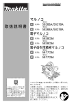
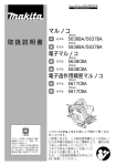
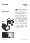
Technical Material
Overview and characteristics of fan
Overview
A cooling fan is widely used to extend life of your system by cooling off heat of the system that many electrical components are mounted
in a very high density and dissipating heat. Since we Sanyo Denki developed San Ace which is the first AC fan in Japan in 1965, we have
increased fan motor lineup until now meeting customer s needs rapidly based on our tremendous career. We Sanyo Denki will continue to
develop new fans with high air flow, low noise, low vibration, and energy - saving design.
Characteristics
We can roughly devide fan into two types which are AC and DC.
AC Fans
DC Fans
Sanyo Denki succeeded in the mass-production of AC fans in
1965. Sanyo Denki was the first Japanese manufacturer to have
succeeded at this.
●High performance
●High reliability
●Safety
Sanyo Denki succeeded in the mass-production of DC fans in 1982.
●High performance
●Low power consumption
●Low vibration
●Low leakage of flux
●High reliability
Sanyo Denki currently has a wider variety of products like Long Life Fan, CPU cooler, Splash Proof Fan, and Oil Proof Fan etc to meet all
customer needs.
Guideline in selecting a fan
How to select an appropriate fan
The following example is a guideline regarding how to select an appropriate fan for cooling your system
1. Determining of your system specifications
and conditions
Determine the temperature rise inside your system and obtain the total heating value
inside your system on the basis of its inputs and outputs.
Example
V : Total heating value of your system(W)=100(W)
△T : Inside temperature rise(K)=15(K)
System
Fan
℃
T
Q'
V
2. Calculating the Required Air flow for Cooling
Heat source
After the equipment specifications and conditions of your system have been determined, calculate required air flow to meet the conditions.
(Note that the formula shown below only applies when the heat radiation is performed only by cooling air from the fan.)
Example
Q': Motion air flow(m3/min)
V
100(W)
≒0.33(m3/min)
Q =
=
20×15(K)
20△T
3. Selecting the Fan
After the motion air flow has been calculated, select an appropriate fan motor based on the value.The motion air flow when the fan
motor is actually mounted in your system can be obtained using the air flow-static pressure characteristics curve and system impedance.
However, the system impedance cannot be measured without a measuring equipment, so fan with 1.5 to 2 times higher air flow than the
actual Max air flow should be selected (operating air flow is one-third to two-thirds of maximum air flow).
Example
Q: Maximum air flow(m3/min)
Characteristics of air flow versus static pressure
Q =Q×2/3
Q=Q ×3/2=0.33×3/2≒0.5(m3/min)
Next, In case that you select a fan having an air flow of 0.5 (m3/min) or more and a appropriate
size for the space inside your system.
For example, If you need a fan of 60mm square, 25mm thickness and 12V, you should select
is 109R0612H402 (maximum air flow = 0.53m3/min).
4. Confirming the Selected Fan
Calculate the temperature rise inside your sysetem when your sysetem having 100 (W) of
total heating value is forcefully cooled down by a 109R0612H402 fan.
Example
Q =Q×2/3=0.53×2/3≒0.353(m3/min)
△T =V/20Q =100(W)/20×0.353(m3/min)≒14.2(K)
From the above, the temperature rise inside your system is calculated as 14.2(K).
and those of pressure losses of equipment
Static pressure
System impedance
Pressure loss
Operating air flow
Air flow
Since the value obtained from the above equation is only a rough target, final fan selection should be based on your actual installation test.
347
Characteristics calculation method and description
Reliability and Life Expectancy
conducted on the basis of the concept that the expected life halves
as the ambient temperature rises by about 15℃ (within the operating
temperature range of lubricant.)
Expected life of DC Fans
Expected life (h)
A cooling fan generally cools itself as well. The temperature rise
of the motor is relatively low and the temperature rise of the
grease in the bearings is also low, so expected life is longer than
general some either motors. Since the service life of bearings is
a theoretical value that applies when they are ideally lubricated,
the life of lubricant can be regarded as expected life of the fan.
DC fan consumes less power and its temperature rise of bearing
is very low, thus its expected life is 40,000 hours at an ambient
temperature of 60℃(60,000 hours for some models). Sanyo Denki
also has a line-up of long life fans that has 200,000 hours life and
100,000 hours life at an ambient temperature 60℃ with an even
more enhanced structure and material. When the measurement
conditions are: L10 (the remaining product life in the lifespan test
is 90%),with an atmospheric temperature of 60 degrees, at the
rated voltage, and continuously run in a free air state. The table
below indicates the relationship between ambient temperature
and expected life estimated on the basis of our life tests and same
other tests conducted by Sanyo Denki. An accelerated life test is
1,000,000
Expected life 200,000h (L10, 60͠)
Expected life 80,000h (L10, 60͠)
Expected life 180,000h (L10, 60͠)
Expected life 60,000h (L10, 60͠)
Expected life 100,000h (L10, 60͠)
100,000
Expected life 40,000h (L10, 60͠)
10,000
Expected life 30,000h (L10, 60͠)
1,000
20
40
60
80
100
Ambient temperature (͠)
Rated voltage, continuously run in a free air state, survival rate of 90%
Noise characteristics
Noise is average value that measured at l meter away from air intake side of fan
that is suspended on special frame in anechoic chamber (as per JIS B 8330).
Fan
Noise meter
1m
Technical Material
AIR FLOW
Acoustic radio wave anechoic chamber
Noise characteristic measurement equipment
Measuring air flow and static pressure
It is very difficult to measure air flow and static pressure. In fact,
the performance curve may vary greatly according to the type of
measuring equiment.
The commonly-used type of measuring equipment is a wind tunnel
using a Pitot tube. Sanyo Denki uses a very precise method using
double chamber equipped with many nozzles.
U-shaped tube
Throttle device
Pn
Ps
Chamber B
U-shaped tube
Q =60A v¯( A)
where
Q = air flow(m3/min)
π
D2(m2)
A = cross sectional area of nozzle=−
4
D = nozzle diameter
─(m/sec)
v¯ = average air flow velocity of nozzle= 2g Pn
γ
γ : Air specific gravity(kg/m3)
(γ=1.2kg/m3 at 20℃ , 1 atmospheric pressure)
g = acceleration of gravity = 9.8(m/sec2)
Pn= differential pressure(mm H2O)
Ps = static pressure(mm H2O)
Chamber A
Nozzle
BM
Auxiliary blower
Fan to be measured
Double chamber measuring equipment
The measuring equipment using double chanber is method to
be calculated from air flow goes through nozzle and differential
pressure between pressure of inside of chamber (Ps) and
atomospheric pressure by measuring differetial pressure between
air intake and exhaust of nozzle (Pn).
Conversion Table
Static pressure
1mm H2O=0.0394inch H2O
1mm H2O=9.8Pa(Pascal)
1inch H2O=25.4mm H2O
1Pa=0.102mm H2O
1inch H2O=249Pa
Air flow
1m3/min=35.31ft 3/min(CFM)
1CFM=0.0283m3/min
1m3/min=16.67ℓ /sec
1CFM=0.472ℓ /sec
1ℓ /sec=0.06m3/min
348
Technical Material
DC Fan Common Specifications
Material
‥‥‥‥‥‥‥‥‥Frame,Impeller:Plastics / Frame:Aluminum,Impeller:Plastics
* For details, refer to the appropriate page.
Life Expectancy
‥‥‥‥‥Varies for each model (L10:Survival rate:90% at 60℃ ,rated voltage, and continuously run in a free air state)
* Splash proof fan: Varies for each model (Indoor, L10:Survival rate:90% at 60 ℃ ,rated voltage, and continuously
run in a free air state)
Motor Protection ‥‥‥‥‥Burnout protection at locked rotor condition and Reverse polarity protection
Dielectric Strength ‥‥‥AC50/60Hz 500VAC 1minute(between lead conductor and frame)
Insulation Resistance ‥‥10MΩ or more at 500VDC megger (between lead conductor and frame)
Sound Pressure Level(SPL) ‥Expressed as the value at 1m from air inlet side
Storage Temperature ‥‥-20℃ to +70℃ / -30℃ to +70℃ (Varies depending on models. Non-condensing)
Lead Wire ‥‥‥‥‥‥‥‥For details, refer to the appropriate page.
Overheating protection function
Protection Functions:
If the fan blades are restricted, an overcurrent occurs and leads to a rise in the fan coil temperature. This can result in reduced
performance, damage, or a fire. To prevent this from occurring, Sanyo Denki s fans incorporate an overheating protection function. Refer
to the catalog for the types of protection functions.
Burnout protection function at locked rotor condition
● Current cutoff system
If the fan blades are restricted, the coil current is cut off at regular cycles to prevent overheating of the coil. When the hindrance is
removed, the fan restarts automatically. (For the San Ace 200〈Model. No: 9EC20****, 9GV20****〉, however, the power needs to
be turned off and on again to restart.).
Reverse polarity protection function
No problem about fan even if positive & negative lead are connected in reverse.
(However fans with sensor & speed control are excluded.)
Specifications for DC fan sensors
Pulse sensor (Tach output type) example
Pulse sensor outputs two pulse waves per revolution of fan, and it is good to detect fan speed. Pulse sensors can be incorporated in all kinds
of DC fans.
* Noise from inside the fan or from external devices may effect sensor output.
Contact us for more information.
The special IC that detects a pulse sensor and raises the alarm is available. Refer to page 346.
● Typical standard model: 9G1212H101.
Output
circuit
Output waveform(Need
Open collector
One revolution
T0
Specifications
VCE=+30V MAX.
T1
(For a 48V-rated fan:Vce=+60V MAX.)
Ic=10mA MAX.[Vol=Vce(SAT)=0.4V or less]
Inside of DC fan
SENSOR
T2
T3
T4
VOH
VOL
0V
+
○
Resistor
+30V MAX.
T1 to 4≒
(1/4)
T0
T1 to 4≒
(1/4)
T0=60/4N
(sec)
-1
N=Fan speed
(min )
Ic=10mA MAX.
Sensor output
−
○
* If you want detailed specifications that apply when the rotor is locked, please contact Sanyo Denki.
349
pull-up resistor)
In case of steady running
Locked rotor sensor (rotation/lock detection type) example
Locked rotor sensor outputs fan status signals. It is good to check whether the fan is running or locked
* Noise from inside the fan or from external devices may effect sensor output.
* Regarding details of the reverse logic and specifications of lock sensor output signals, please contact Sanyo Denki.
* Lock sensor can not be used in some models. Contact us for more information.
● Typical standard model: 9G1212H1D01.
Output circuit
Output waveform (Need
Open collector
Rotor
running
Specifications
0.5 or less
VCE=+27.6V MAX.
For a 48V fan VCE =+60V MAX.
Ic=5mA MAX.[VOL=VCE(SAT)=0.6V or less]
For a 48V fan:VCE(SAT)=0.4V or less
pull-up resistor)
Rotor
locked
5 or less
Rotor
running
3 or less
VOH
VOL
0V
Inside of DC fan
Time(sec)
+
○
SENSOR
Resistor
+27.6V MAX.
Note: The output is completely at Vol with 0.5 seconds or less
after power-up.
Ic=5mA MAX.
Sensor output
−
○
Low-speed sensor (rotating speed detection type) example
Technical Material
Low-speed sensor outputs a signal when fan speed goes down to trip point or less. It is good to detect cooling degradation of fan.
*Noise from inside the fan or from external devices may effect sensor output, please.
* If you want detailed specification and reverse signal output,please contact Sanyo Denki.
(typical standard model: 109R1212H1H01)
*Low-speed sensors can not be used in some models. Contact us for more information.
● Typical standard model: 9G1212H1H01.
Inside of DC fan
Output circuit
+
○
Open collector
SENSOR
Specifications
Resistor
+27.6V MAX.
Ic=10mA MAX.
Sensor output
VCE=27.6V MAX.
Ic=10mA MAX.[VOL=VCE(SAT)=0.5V or less]
−
○
Sensor scheme
Example 1:
In case steady running
Example 2:
In case that the rotor is locked when the fan motor is turned on
and released after the start-up delay time.
Fan power
Fan power
Trip point
Fan speed
Trip point
Fan speed
Startup delay
Sensor output
Detected delay
H
Startup delay
H
L
(SAT)
VCE
Sensor output
Detected delay
H
H
L
350
Technical Material
PWM Speed Control Function
The PWM speed control function is a function that externally controls the rotation speed of the fan by changing the duty of the input pulse
signal between the control terminal and GND.
It regulates optimum airflow for efficient cooling when necessary, and is effective for lowering power consumption and reducing equipment
noise level.
* Some models can not have PWM speed control function. Contact us for more information.
● Typical standard model: 9G0812P1G04
■ PWM Duty - Speed Characteristics
Voltage : 12V DC
7000
PWM Frequency:25kHz
6300min-1
6000
Duty cycle=20%
5000
A 5V
Speed
(min-1)
4100min-1
4000
0V
Fan speed
36% speed(2300min-1)
of full speed
Duty cycle=50%
3000
B
2300min-1
5V
0V
65% speed
(4100min-1)
of full speed
2000
Duty cycle=100%
1000
5V
C 0V
0
0%
20%
50%
100%
A
B
C
Full speed
(6300min-1)
PWM Duty Cycle
■ PWM Input Signal
Input Signal Wave Form
VIH = 4.75V to 5.25V
VIH
V IL = 0V to 0.4V
VIL
PWM Duty Cycle(%) = T1 ×100
T
PWM Frequency 25 (kHz) = 1
T
Source Current ( I source ) : 1mA Max. at control voltage 0V
T1
Sink Current ( I sink ) : 1mA Max. at control voltage 5.25V
T
Control Terminal Voltage : 5.25V Max. ( When control terminal is opened )
When the control lead wire is open, the fan speed is the same as the one at a PWM duty cycle of 100%.
Either TTL input, open collector or open drain can be used for PWM control input signal.
■ Example of Connection Schematic
Inside of DC fan
DC fan power
Source Current ( I source ) : 1mA Max. at control voltage 0V
Sink Current ( I sink ) : 1mA Max. at control voltage 5.25V
Control Terminal Voltage : 5.25V Max. ( When control terminal is opened )
Control Terminal
PWM signal
351
Isource
Isink
Splash Proof Fan
Ingress Protection Ratings (IP Code)
■ IP Codes used by SANYO DENKI express the level of protection that internal electrical components (for fans: electrical
components and motor coils) have against solid objects, water, and access to hazardous parts.
San Ace Splash Proof fans feature high protection levels.
Protected electrical components and motor coils
■ Definition of Ingress Protection (IP Code)
Ingress Protection (IP Code) is defined in IEC (International Electrotechnical Commission) 60529*
DEGREES OF PROTECTION PROVIDED BY ENCLOSURES (IP Code). *IEC 60529:2001
I P X X
Second digit: Protection against water
First digit
Defi nition
0
No protection
1
Protection against solid objects > 50 mm
2
Protection against solid objects > 12.5 mm
3
Protection against solid objects > 2.5 mm
4
Protection against solid objects > 1 mm
5
Protection against a level of dust that could hinder operation or impair safety
6
Complete protection against dust
Second digit
Technical Material
First digit: Protection against solid objects and access to hazardous parts
Defi nition
0
No protection
1
Protection against dripping water
2
Protection against water spray up to 15°
3
Protection against spraying water
4
Protection against splashing water
5
Protection against low pressure water jets
6
Protection against high pressure water jets
7
Protection against temporary immersion in water
8
Protection against submersion in water
352
Technical Material
Thermal speed controlled fans with an external or built-in thermistor
External thermistor type
1. Overview
For thermal speed controlled fans with an external thermistor, just connect a specified thermistor
(or a specified thermistor and a resistor) between the control wire and the negative wire indicated in
Fig. 1, it will enable the fan speed to change automatically according to a predetermined temperature
speed specification and according to temperature changes in an environment where the thermistor is
equipped .(Please refe to Fig. 2)
Fan
(Red)
E
(Black)
Control
(Brown)
Thermistor
Change in speed
(%)
Fig. 1
A thermistor can therefore be installed at an appropriate position inside your equipment to monitor the
internal temperature changes due to changes in ambient temperature and heatup status (load status)
of the equipment. Automatic monitoring can then specify low speed when the thermistor detects a
temperature below TL, high speed when it detects a temperature above TH, and a speed according to
the temperature when it detects a temperature between TL and TH.
Thus, the fan detects its own operational status and determines the operating conditions.
As a result, the thermal speed controlled fan with an external thermistor is designed that temperature
changes according to the ambient temperature and operational status of the equipment are detected
by the thermistor to control the fan's air flow (speed), and is near-ideal particularly in designing silent
equipment. The fan thus meets the three requirements: silence, energy-saving, and long life.
100
50
High speed
Low speed
Variable speed in linear
0
TL
Thermistor temperature
(℃)
TH
Fig. 2
2. Setting temperatures (TL and TH) in low and high speed
The standard products listed in this catalog are designed to run at a
low speed at 28℃ or below and run at a high speed at 35℃ or more
when a recommended thermistor is connected between the control
wire and the negative wire.
These temperatures (TL and TH) can be changed (as indicated in Table 1)
by inserting a resistor in series with the thermistor.
* For the resistor Rs,
Table 1
Resistance Rs
(Ω)
Fan
Control
Resistor Rs
Recommended thermistor
0
0.8K
1.5K
2.0K
2.4K
2.75K
Temperature setting(℃)
TL
28
31.5
35
38
40.5
43
TH
35
40
45
50
55
60
use a resistor rated
at no less than
1/8W.
* Manufactured
by
OHIZUMI MGF
CO.,LTD.
3. If you wish to obtain low or high speed in a process of testing by using a larger equipment
regardless of the thermistor temperature:
Low speed :
High speed :
Instead of the thermistor, connect a 10 KΩ resistor between the control wire and the negative wire.
Connect the control wire directly to the negative wire.
4. Connecting the fan to the thermistor
Sanyo Denki recommends to use connectors,
including the power lead of the fan.
Example of Typical connections :place a
thermistor on the printed circuit board and
connect the fan's power lead and control lead
to the circuit pattern by means of connectors.
Recommended connectors
Printed circuit board of the equipment
Thermistor
Manufacturer
Model (3-pole)
Japan Solderless Terminals
XHP-3,SMR-3V-N
Japan Aviation Electronics Industry
IL-G-3S-S3C2-SA
Connector
Japan AMP
171822-3
Molex Japan
51191-0300
Rotation speed min-1(r.p.m)
5. Typical applications of thermal speed controlled fans with an external thermistor
Here are typical applications of a thermal speed controlled fan with
Cooling fan
a power supply where two 109P1212H402 fans are used (Fig. 5).
2800min-1
(1) The fan selected was a 109P1212T4H12 thermal speed
1400min-1
controlled fan having a performance equal to that of
conventional fans at high speed.
(2) The relationship between the temperatures of important
0
35
45
Thermistor temperature(℃)
components and those of the cooling fin can be measured with
Fig. 5
Fig. 6
varied loads on the equipment and varied air flows of the fan.
Noise level reduction
* An ideal drop in the fan noise level was
-2dB(A)
Since a correlation was determined, the thermistor can then be
-6dB(A)
achieved according to the equipment
45 Equipment noise (dB (A))
-9dB(A)
43
-12dB(A)
39
load. When the equipment load was 0,
placed on the cooling fin, one of the important components.
56 Temperature rise in parts
36
(℃)
47
the noise was 12dB (A) lower than in the
33
(3) Next, in view of the thermal design conditions of the
33
case of conventional models.
24
2470 Rotating speed(min )
2230
equipment, the fan is set to high speed at an ambient
*
The
current consumption of the fan
(operating point)
9
1880
1670
was 54% lower than in the case
1340
temperature of 30℃ and an equipment load of 100%.
Input
current
of
fan
0.48
0.38
of conventional models when the
0.27
(A)
0.25
0.22
(4) At an ambient temperature of 30℃ and an equipment load of
equipment load was 0.
Equipment load(%)
0
50
100
* The noise level is expected to decline
100%, the temperature of the cooling fin was 48℃ and the
Fig. 7
further at lower ambient temperatures.
surface temperature of the thermistor placed on the cooling
fin was 45℃ when the fan was running at high speed. It was therefore decided to add a 1.5 K Ω resistor in series with the thermistor according to
Table 1. In this case, the thermistor temperature is 35℃ and the fan runs at low (see Table 1 and Fig. 6).
(5) Test results as installed on equipment: The thermal speed controlled fan displayed its full effect, thus being greatly advantageous in noise
reduction. The ambient temperature during the test was 29℃ .
-1
353
Built-in thermistor type
(Red)
(Black)
Thermistor
E
Fig. 8
2. Typical applications of thermal speed
controlled fans with a built-in thermistor
Fig. 10
(Standard values: TL = 30℃, TH = 40℃)
100
Fast rotation
Slow rotation
Speed-variable domain
TH
60
Part temperature(CPU )
50
Temperature (℃) of air flowing
through the fan
Part temperature(CPU)
40
40
30
30
Temperature of air flowing through the fan
Ambient temperature of equipment
PC
TL
Fan rotating speed
109R0812T4H122
2000
Fig. 9
0
Fig. 11
70
3000
Thermostatic chamber
50
Temperature
(℃)
Fig. 11 indicates measurements taken when a 109R0812T4H122 fan
is mounted on equipment (a PC) is tested in the state as illustrated in
Fig. 10.
Heater
Fan
Rotation speed change(%)
Thermal speed controlled fans with a built-in thermistor are designed
that the fan it self contains a thermistor as indicated in Fig. 8. As
illustrated in Fig. 9, the temperature of the air flowing through the
fan motor is detected and the fan's speed changes automatically
according to changes in that temperature.
Rotation speed
(min-1)
1. Overview
Temperature of air flowing through the fan
20
1000
20 23
30
35
40 Ambient temperature(℃)of equipment
UPS, inverter, rectifier, high-voltage power supply, etc.
Cautions for use of a cooling fan in the vicinity of a power switching circuit (prevention of electrolytic corrosion)
Custom Product
Refer to page 340
If a fan is installed near a large-power or high-voltage switching circuit, the heavy electromagnetic noise resulting from electromagnetic
induction in such circuits or the influence of high-frequency noise imposed through the power line of the fan may induce current through the
shaft bearing of the fan.Such current may damage the oil film on the bearing and even the friction surface of the bearing.This adverse effect
is known as "electrolytic corrosion of the fan."Electrolytic corrosion affects the smooth revolution of the fan and may reduce its service life. An
audible symptom is unusual noise emitted from the fan.This adverse effect is often observed and may partly be explained by the practice of
mounting high-density parts, which reduces the gap between the switching circuits and the fan and the use of higher switching frequencies apt
to provoke induction. Data processing/communications devices that operate at low voltages are not liable to electrolytic corrosion since they
generate less electromagnetic noise.
A Case of Electrolytic Corrosion
Use
Switching power supply
UPS
General-purpose inverter
Air cleaner
Inverter for LCDs
Period until the occurrence of unusual noise
6 months to 2 years
6 months to 2 years
1 to 1.5 years
2 to 3 months
6 months
Technical Material
No.
1
2
3
4
5
The curve shown in the graph below represents the relationship
between the level of the electromagnetic noise induced by a fan
and the distance from the fan to the noise source.
Level of noise induced by a fan
Fans without anti-corrosion features installed near components that
generate electromagnetic noise, such as inverter controllers, are
liable to experience electrolytic corrosion.
Range in which electrolytic
corrosion is generated
Range in which electrolytic
corrosion is not generated
Distance from the noise source to the fan
Occurrence of electrolytic corrosion Pattern 1
(1)The fan gets charged with high-frequency electricity by high-frequency noise (electric field/magnetic
field) generated in the switching circuit.
(2)Because of high-frequency electricity charged in the fan, an electric current flows through the bearing of the fan.
(3)The electric current breaks the oil membrane on the surface of the bearing and the bearing gets abraded (electrolytically corroded).
(4)This symptom often occurs in equipment in which switching circuits are sped up and implemented in high density.
(5)Countermeasure 1: To provide a shield plate (Note 1) inside the fan (The plate should be such that does not interfere with air flow).
(6)Countermeasure 2: To use a fan with ceramic bearings.
Occurrence of electrolytic corrosion Pattern 2
(1)High-frequency electricity flows from the circuit board into the inside of the fan superimposed with the power line for the
fan.
(2)High-frequency electricity that has entered into the fan flows through the bearing.
(3)Oil membrane on the surface of the bearing gets broken and the bearing gets abraded (electrolytically
corroded).
(4)Countermeasure 1: To remove high-frequency component between terminals "a" and "b", "a" and "e" and "b" and
"e" of the power supply for the fan, or to insert a filter (Note 2) into the power line for the fan.
(5)Countermeasure 2: To use a fan with ceramic bearings (6)Cables should be twisted in order to decrease induction to the power line for the fan.
Fan cabinet
Switching circuit board of the equipment
Component parts of
the switching circuit
Propeller
Pattern 1
Electric field/magnetic field of
the high-frequency electricity
Shielding metal
+ terminal a
Power supply for the fan
0Vterminal
(Grounding to the cabinet)
Wind
Mounting
screw
b
Pattern 2
High-frequency electricity is superimposed
onto the power line for the fan.
Circuit board grounding
e
Metal cabinet of the equipment
Return path of the high-frequency electricity
Note 1:Shielding metal plate
As an electromagnetic shield metal, "EMC Guard" is available from our company. http://www.sanyodenki.co.jp/product /newfan/indexf.html
Certain shielding effect can be expected from mounting a general-purpose finger guard inside the fan. In each case, grounding to the cabinet is required.
Note2:Filter
Insert a common mode filter when the high-frequency electricity is superimposed on both lines "a" and "b" in the same phase and, if not, insert a normal mode filter.
Measures against Electrolytic Corrosion
(1) Relocate fans far from all electromagnetic noise sources.
(2) Use anti-corrosion fans equipped with ceramic bearings.
(3) Attach an EMC guard to ordinary fans.
(4) As a power supply, the fan is wired from a circuit for which noise is not superimposed.
*The EMC guard could be effective against electromagnetic noise caused by radiation, but against heavy electromagnetic noise (electromagnetic induction)
and conductive noise from the power supply line for a fan, we recommend the use of an "anti-electrolytic corrosion fan" with ceramic bearing.
354
Technical Material
Operating precautions
Storage temperature
There is no performance problem when the system is used at between -30℃ and +70℃ . There is a possibility that same problem of
lubricant and insulation inside motor might occur by condensing due to rapid surrounding temperature change. Therefore, please take care
of non-condensing using desiccant or something during fan is in storage.
Handling precautions
The fan motor is equipped with a precision ball bearing. Therefore, please handle the motors carefully in order not to shock the bearings.
Recommended screw torque
Installation
This shows the recommended values for the screw torque when
installing the fans. If the tightening torque is higher than the
recommended values, the fan can be deformed or damaged.
Use care when tightening. Also, be sure to always use a fan with a
ribbed structure when using screws to pass through and secure the fan.
Fans : 0.44N・m (4.5kgf・cm) or less (with M3 screws)
(Applies to fan motors of 52mm×52mm MAX.)
Fans : 0.78N・m (8kgf・cm) or less (with M4 screws)
(Applies to fan motors of 60mm×60mm MIN.)
Fans : 0.98N・m (10kgf・cm) or less (with M4 screws)
(φ200mm)
There are no limitations on the installation direction of fans or
blowers. Fans have symbols on the fan indicating the airflow
direction and blade rotation direction. When installing, use these
symbols to check the airflow direction.
Air Flow direction
Discharge side
Suction side
Blade rotation direction
Symbols indicating the fan airflow direction and blade rotation direction
Comparison of ribbed and ribless structures
Regarding plastic frame, we have a option ribbed and ribless about mounting. Please use preferred type up to your application. Please use ribbed fan in
case that you hook fan up clamping either side fan mounting hole target. (According to the model, only models with or without ribs are available.)
*Use a fan with a rib structure when using a screw for piercing.
・When securing screws to ribless plastic frame models, use a flange to
secure on one side.
Rib
Ribbed
355
Ribless
Securing with flanges
on both sides
Securing with a flange
on one side
Fan mounting using self-tapping screw
[For nominal diameters of 4.8mm and 5mm]
Self-tapping screw model No.
SY-NS024812P15
SY-NS020512P15
0.5
Min.
0.5以上
Installing self-tapping screws into the plastic frame of the fan may
split or deform it.
If you use self-tapping screws, use screws that are recommended
by our company, and refer to our recommended screw torques
and recommended pilot hole shapes. Pay close attention to the
operating precautions and fully understand your equipment before
you use it.
Self-tapping screw model No.
SY-NS014812P15
SY-NS010512P15
120°
Ø5.6
板金
Plate
Ø5.6
ファンフレーム
Fan
frame
板金
Plate
ファンフレーム
Fan
frame
Minimum mounting plate thickness: T=1.2mm
Operating precautions
・ Place the self-tapping screw so that it is vertical and centered
Fig. A: Ribbed fan
Ribbed fan (Fig. A)
Fig. B: Counter rotating fan
Fan mounting hole
diameter [mm]
Recommended screw
torque [N·m]
Ø3.5,Ø4.3,Ø4.5
0.8 Max.
Ø3.5,Ø4.3
0.6 Max.
Counter rotating fan
(Fig. B)
with the frame mounting hole (Fig. A) and then screw it in. The
self-tapping screw could deform or split the frame if you screw it
into the frame when the screw is not vertical.
・ Screw in the self-tapping screw with the center of the mounting
hole on the fan and the center of the pilot hole on the mounting
plate aligned (Fig. B). Misaligned holes could lead to the frame
being deformed or split.
Recommended self-tapping screws
・Material: Steel
Ø3.5
Ø4.3
Ø4.5
Unit: mm
Flat-head/pan-head dimensions
Nominal
Length Head
Self-tapping screw
Height of Cross
Head
screw
[L] shape diameter
model No.
recess
head
diameter
No.
[H]
[D]
1.1 Max.
2
SY-NS020412P11
4
12
Flat
6.2
SY-NS010412P11
4
12
Pan
5.5
2.0
2
2
SY-NS024812P15
4.8
12
Flat
6.8
1.2 Max.
SY-NS014812P15
4.8
12
Pan
7.0
2.6
2
SY-NS020512P15
5
12
Flat
6.8
1.2 Max.
2
SY-NS010512P15
5
12
Pan
7.0
2.6
2
頭形状
:皿 Flat
Head
shape:
Inclined
screw
ネジの傾き
Fig. A
D
D
120°
L
L
H
Vertically
placed screw
ネジの垂直
頭形状
:なべPan
Head
shape:
H
Fan
mounting
hole
diameter
Technical Material
・Plating: Trivalent chromating plating
Aligned穴の中心一致
and centered holes
穴の中心ずれ
Misaligned
holes
Fig. B
・ Never use self-tapping screws to mount a fan with a ribless frame
(not including counter rotating fan).
Recommended pilot hole shape
・ Tightening the screw beyond the recommended screw torque
[For nominal diameter 4mm]
0.5
Min.
0.5以上
Self-tapping screw model No.
SY-NS020412P11
could deform or split the frame.
Self-tapping screw model No.
SY-NS010412P11
120°
Ø4.6
Ø4.6
板金
Plate
ファンフレーム
Fan
frame
Minimum mounting plate thickness: T=1.2mm
板金
Plate
ファンフレーム
Fan
frame
・ With flat-head screws, failure to use the recommended pilot hole
shape will cause interference between the flat-head screw and
fan frame which could split the frame.
・ Do not use self-tapping screws to mount the finger guard on the
fan. Using self-tapping screws could deform or split the frame.
Recommended screw manufacturer
To purchase the screws, please contact the screw manufacturer
directly.
SAIMA CORPORATION
2-9-17 Tsujido Fujisawa Kanagawa 251-0047 JAPAN
TEL:+81-466-36-3656 FAX:+81-466-36-0009
http://www.saima.co.jp/English/
356