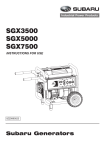
1
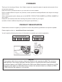
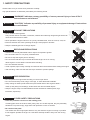
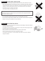
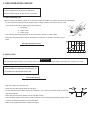
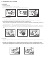
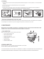
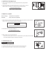
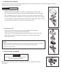
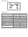
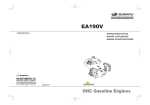
SP170/210 INSTRUCTIONS FOR USE MANUEL D’UTILISATION MANUAL DE INSTRUCCIONES 20A9991401 OHC Gasoline Engines Limited Engine Warranty (Effective with engines purchased from Robin America, Inc., Lake Zurich, IL, after April 1, 2008) Robin America, Inc., a division of Fuji Heavy Industries, Ltd. (herein “Subaru”), warrants that each new engine sold by it will be free, under normal use and service, from defects in material and workmanship for a period listed below from the date of sale to the original retail purchaser. Subaru’s obligation under this Limited warranty shall be limited to the repair and replacement, at Subaru’s option, of any part or parts which upon examination is/are found, in Subaru’s judgment, to have been defective in material or workmanship. It shall be a condition of Subaru’s obligation under this Limited Warranty that Subaru, directly or through one of its Distributors or Service Centers authorized to service the particular engine involved, receive prompt notice of any warranty claim and that the engine or the part or parts claimed to be defective be promptly delivered, transportation prepaid, to such distributor or service Center for inspection and repair. All repairs qualifying under this Limited Warranty must be performed by Subaru or one of its authorized Distributors or Service Centers. WARRANTY PERIODS: SP170, Gasoline Engines Limited 3 year Warranty SP210, Gasoline Engines Limited 1 year Warranty To Qualify for this Warranty: Subaru Industrial Engines must be purchased from a Subaru engine dealer or distributor authorized to sell that product in North America. The repair or replacement of any part or parts under this Limited Warranty shall not extend the term of the engine warranty beyond the original term as set forth above. LIMITATIONS AND EXCLUSIONS: This Limited Warranty shall not apply to: 1. Bent or broken crankshaft or resultant damage caused by vibration related to a bent or broken crankshaft. Also, damage caused by loose engine mounting bolts or improper or imbalanced accessories or blades mounted to the crankshaft. 2. Repairs required because of prolonged storage including damage caused by old or contaminated fuel in the fuel tank, fuel lines or carburetor, sticky valves or corrosion and rust of engine parts. 3. Repair required due to overheating. (Most often caused by overloaded or clogged or damaged or missing flywheel, fan, inlet air passages, cooling fins or air shrouds.) 4. Dirt or grit related wear caused by improper air cleaner maintenance (most often resulting in worn piston, piston rings, cylinders, valves, valve guides, carburetor or other internal components). 5. Broken or scored parts caused by low oil level, dirty or improper grade of oil. 6. Engine tune-ups and normal maintenance service including, but not limited to, valve adjustment, normal replacement of service items, fuel and lubricating oil, etc. 7. Any engine which has been subject to negligence, misuse, accident, mis-application or over-speeding. 8. Any engine that has been installed, repaired, or altered by anyone in a manner which in Subaru’s sole judgment adversely affects its performance or reliability. 9. Any engine which has been fitted with or repaired with parts or components not manufactured or approved by Subaru which in Subaru’s sole judgment adversely affects its performance or reliability. 10. Instances when normal use has exhausted the life of a component or an engine. The customer is responsible for all transportation charges in connection with any warranty work. Subaru reserves the right to modify, alter or improve any engines or parts without incurring any obligation to modify or replace, any engine or parts previously sold without such modification, alternation or improvement. No person is authorized to give any other warranty or to assume any additional obligation on Subaru’s behalf unless made in written and signed by an officer of Subaru. THIS WARRANTY, AND SUBARU’S OBLIGATION HERE UNDER, ARE IN LIEU OF ANY OTHER WARRANTIES OR OBLIGATIONS OF ANY KIND, EXPRESSED OR IMPLIED, INCLUDING ANY WARRANTIES OF MERCHANTABILITY OR FITNESS FOR A PARTICULAR PURPOSE. THERE ARE NO WARRANTIES WHICH EXTEND BEYOND THE DESCRIPTION ON THE FACE HERE-OF. SUBARU SHALL IN NO EVENT BE LIABLE FOR ANY CONSEQUENTIAL OR INCIDENTAL DAMAGES. WORLD WIDE SUPPORT Subaru Engines are supported through a network of dozens of wholesale distributors and thousands of service dealers worldwide. Please use the following contacts to find support nearest you. Global Distributor Locator: www.subaru-robin.jp/index_e.html North America: Subaru Robin America, Inc. 905 Telser Road Lake Zurich, IL 60047 U.S.A. Tel.: 847-540-7300 • Fax: 847-438-5012 Email: [email protected] Web: www.subarupower.com Service Dealer Locator: www.subarupower.com/dealerusacan.aspx Asia: Fuji Heavy Industries LTD. (Parent Company of Subaru) 4-410, Asahi, Kitamoto-shi Saitama 364-8511, Japan Tel.: 81-48-593-7941 • 81-48-593-7965 Web: www.subaru-robin.jp/index_e.html Europe: Subaru Robin Europe GmbH Willicher Damm 135-137 D-41066 Mönchengladbach Tel.: +49 - (0)2161 - 63620 - 0 • Fax: +49 - (0)2161 - 63620-50 E-Mail: [email protected] Web: www.robin-europe.de/html/eindex.htm Australia: Crommelins Machinery 139 Welshpool Rd Welshpool 6106 Tel.: (08) 9350 5588 • Fax: (08) 9451 6381 E-mail: [email protected] Web: www.crommelins.com.au (California Proposition 65) ! WARNING ▲ The engine exhaust from this product contains chemicals known to the State of California to cause cancer, birth defects or other reproductive harm. (California only) AIR INDEX To show compliance with California emission regulations, a hangtag has been provided displaying the Air Index level and durability period of this engine. The Air Index level defines how clean an engine’s exhaust is over a period of time. A bar graph scaled for “0” (most clean) to “10” (least clean) is used to show an engine’s Air Index level. A lower Air Index level represents cleaner exhaust from an engine. The period of time (in hours) that the Air Index level is measured is known as the durability period. Depending on the size of the engine, a selection of time periods can be used to measure the Air Index level (see below). Descriptive Term Applicable to Emissions Durability Period Moderate 50 hours 125 hours (engine from 0 to 80cc) (engine greater than 80cc) Intermediate 125 hours (engine from 0 to 80cc) 250 hours (engine greater than 80cc) Extended 300 hours (engine from 0 to 80cc) 500 hours (engine greater than 80cc) 1000 hours (225cc and greater) Notice: This hangtag must remain on this engine or piece of equipment, and only be removed by the ultimate purchaser before operation. Notice: FEDERAL EMISSION COMPONENT DEFECT WARRANTY and CALIFORNIA EMISSION CONTROL WARRANTY are applicable to only those engine / generators complied with EPA (Environmental Protection Agency) and CARB (California Air Resources Board) emission regulations in the U.S.A. Notice: To the engines / generators exported to and used in the countries other than the U.S.A., warranty service shall be performed by the distributor in each country in accordance with the standard Subaru engine / generator warranty policy as applicable. FORWARD Thank you for choosing a Subaru. Your Subaru engine can supply the power to operate various sorts of machines and equipment. Keep this owner’s manual at hand, so you can refer to it when needed. Due to constant efforts to improve our products, certain procedures and specifications are subject to change without notice. When ordering spare parts, always give us the MODEL, PRODUCTION NUMBER and SERIAL NUMBER of your engine. Please fill in the blanks below after checking the product number on your engine. (Location of label is different depending on the engines specification.) PRODUCT REGISTRATION Please take a moment to register your product to ensure easy warranty qualification and product updates. Please register online at: www.SubaruPower.com/register You will need the following two pieces of information to complete your product registration. SPECIFICATION No SERIAL No PROD. No. / SER No. (Label) SER No. ( Stamping ) NOTICE The engines which have emission label are allowed to be exported to USA. The emission label placed on the engine indicates that the engine is complied with EPA (Environmental Protection Agency) and CARB (California Air Resources Board) emission regulations in USA. Exporting any engine to USA which does not have the emission label is a violation of EPA/ CARB emission law subject to civil penalty. CONTENTS 1. Symbols.......................................................................................................................................... 8 2. Safety Precautions.......................................................................................................................... 9 3. Components................................................................................................................................. 12 4. Pre-Operation Checks.................................................................................................................. 13 5. Operating the Engine.................................................................................................................... 14 6. Maintenance................................................................................................................................. 16 7. Preparations for Storage............................................................................................................... 20 8. Easy Troubleshooting................................................................................................................... 21 9. Specifications................................................................................................................................ 22 10. Emission Warranty Statement...................................................................................................... 23 1. SAFETY PRECAUTIONS Please make sure you review each precaution carefully. Pay special attention to statement preceded by the following words. ! WARNING “WARNING” indicates a strong possibility of severe personal injury or loss of life if ▲ instructions are not followed. ! CAUTION ▲ “CAUTION” indicates a possibility of personal injury or equipment damage if instructions are not followed. ! WARNING ▲ EXHAUST PRECAUTIONS •Never inhale exhaust gasses. They contain carbon monoxide, a colorless, odorless and extremely dangerous gas which can cause unconsciousness or death. •Never operate the engine indoors or in a poorly ventilated area, such as a tunnel, cave, etc. •Exercise extreme care when operating the engine near people or animals. •Keep the exhaust pipe free of foreign objects. ! WARNING REFUELING PRECAUTIONS ▲ •Gasoline is extremely flammable and its vapors can explode if ignited. •Do not refuel indoors or in a poorly ventilated area. •Be sure to stop the engine prior to refueling. •Do not remove fuel tank cap nor fill fuel tank while engine is hot or running. Allow engine to cool at least 2 minutes before refueling. •Do not overfill the fuel tank. •If fuel is spilled, wipe it away carefully and wait until the fuel has dried before starting the engine. •After refueling, make sure that the fuel cap is secured to prevent spillage. ! WARNING FIRE PREVENTION ▲ •Do not operate the engine while smoking or near an open flame. •Do not use around dry brush, twigs, cloth rags, or other flammable materials. •Keep cooling air intake (recoil starter area) and muffler side of the engine at least 1 meter (3 feet) away from buildings, obstructions and other burnable objects. •Keep the engine away from flammables and other hazardous material (trash, rags, lubricants, explosives). ! WARNING OTHER SAFETY PRECAUTIONS ▲ •Place the protective covers over the rotating parts. If rotating parts such as the drive shaft, pulley, belt, etc. are left exposed, they are potentially hazardous. To prevent injury, equip them with protective covers or shrouds. •Be careful of hot parts. The muffler and other engine parts become very hot while the engine is running or just after it has stopped. Operate the engine in a safe area and keep children away from the running engine. 1m 1m ! WARNING OTHER SAFETY PRECAUTIONS ▲ •Do not touch the spark plug and ignition cable when starting and operating the engine. •Never make adjustments on the machinery while it is connected to the engine, without first removing the ignition cable from the spark plug. Turning the crankshaft by hand during adjusting or cleaning might start the engine, and cause serious injury to the operator. •Operate the engine on a stable, level surface. If the engine is tilted, fuel spillage may result. NOTE: Operating the engine at a steep incline may cause seizure due to improper lubrication even with a maximum oil level. •Do not transport the engine with fuel in tank or with fuel strainer cock open. •Do not move the engine while in operation when it has been removed from the equipment. •Keep the unit dry (do not operate it in rainy conditions). ! WARNING ▲ PRE-OPERATION CHECKS •Carefully check fuel hoes and joints for looseness and fuel leakage. Leaked fuel creates a potentially dangerous situation. •Check bolts and nuts for looseness. A loose bolt or nut may cause serious engine trouble. •Check the engine oil and refill if necessary. •Keep cylinder fins and recoil starter free of dirt, grass and other debris. •Wear sung fitting working clothes when operating the engine. Loose aprons, towel, belt, etc., may be caught in the engine or drive train, causing a dangerous situation. SYMBOLS Read manual. Shutt off fuel valve when the engine is not in use. Stay clear of the hot surface. Check for leakage from hose and fittings. Exhaust gas is poisonous. Do not operate in an unventilated room or enclosed area. Fire, open flame and smoking prohibited. Stop the engine before refueling. HOT, avoid touching the hot area. On (Run) Engine start (Electric start) Fuel (gasoline) Off (Stop) Engine stop Fuel shut-off Engine oil Fast Fuel system failure / malfunction Add oil Slow Choke Battery Plus ; positive polarity Minus ; negative polarity 2. COMPONENTS 1 Spark Plug 11 Fuel Valve 2 Exhaust Outlet 12 Fuel Cup 3 Muffler Cover 13 Carburetor 4 Air Cleaner 14 P.T.O. Shaft 5 Fuel Tank 15 Oil Gauge (Oil Filler) 6 Fuel Tank Cap 16 Oil Drain Plug 7 Speed Control Lever 17 Engine Serial No 8 Recoil Starter 18 Engine Name Label 9 Starter Handle 19 Stop Switch 10 Choke Lever 20 Oil Sensor Unit 3. PRE-OPERATION CHECKS NOTE Engine shipped from our factory is without oil. Before starting engine, fill with oil. Do not overfill. 1.CHECK ENGINE OIL Before checking or refilling engine oil, be sure the engine is located on a stable, level surface and stopped. •Do not screw the oil gauge into the oil filler neck to check oil level. If the oil level is low, refill to the upper level with the following recommended oil. • 1 - Oil Gauge • 2 - Upper Level • 3 - Lower Level •Use 4-stroke automotive detergent oil of API service class SE or higher grade. •Select the viscosity based on the air temperature at the time of operation as shown in the table. Oil Capacity (Upper Level) SP170/210 0.6 L 2. CHECK FUEL ! WARNING ▲ Do not refuel while smoking, near an open flame or other such potential fire hazards. Otherwise fire accident may occur. NOTE THIS ENGINE IS CERTIFIED TO OPERATE ON AUTOMOTIVE UNLEADED GASOLINE. Fuel Tank Capacity SP170/210 3.4L •Stop the engine and open the cap. •Close the fuel valve before filling the fuel tank. •Do not fill above the fuel filter screen (as marked 2 ), or the fuel may overflow when it heats up later and expands. •When filling the fuel tank, always use the fuel filter screen. •After refueling, tighten the fuel cap (rotate clockwise) until it makes a physical stop, there will be a relief in resistance just before the physical stop. •Wipe off any spilled fuel before starting the engine. 4. OPERATING YOUR ENGINE 1.STARTING 1)Open the fuel valve 2)Turn the STOP SWITCH to the “ON” (I) position 3)Set the speed control lever 1/3 of the way towards the high speed position. 4)Close the choke lever. • If the engine is cold or the ambient temperature is low, close the choke lever fully. • If the engine is warm or the ambient temperature is high, open the choke lever half-way, or keep it fully open. 5)Pull the starter handle slowly until resistance is felt. This is the “compression” point. Return the handle to its original position and pull swiftly. Do not pull out the rope all the way. After starting the engine, al low the starter handle to return to its original position while still holding the handle. 6)After starting the engine, gradually open choke by turning the choke lever and finally keep it fully opened. Do not fully open the choke lever immediately when the engine is cold of the ambient temperature is low, because the engine may stop. 2.RUNNING 1)After the engine starts, set the speed control lever at the low speed position (L) and warm it up without a load for a few minutes. 2)Gradually move the speed control lever toward the high speed position (H) and set it at the required engine speed. • Whenever high speed operation is not required, slow the engine down (idle) by moving the speed control lever to save fuel and extend engine life. 3.STOPPING 1)Set the speed control lever at the low speed position and allow the engine to run at low speed for 1 or 2 minutes before stopping. 2)Turn the STOP SWITCH counterclockwise to the “OFF” (O) position. 3)Close the fuel valve 4)Pull the starter handle slowly and return the handle to it original position when resistance is felt. This operation is necessary to prevent outside moist air from intruding into the combustion chamber. * STOPPING THE ENGINE WITH THE FUEL VALVE Close the fuel valve and wait for awhile until the engine stops. Avoid to let the fuel remain in the carburetor over long periods, or the passages of the carburetor may become clogged with impurities, and malfunction may result. 5. MAINTENANCE MAINTENANCE, REPLACEMENT, OR REPAIR OF THE EMISSION CONTROL DEVICES AND SYSTEMS MAY BE PERFORMED BY ANY NON ROAD ENGINE REPAIR ESTABLISHMENT OR INDIVIDUAL. 1. DAILY INSPECTION Before running the engine, check the following service items. • Loose or broken bolts and nuts • Clean air cleaner element • Enough clean engine oil • Leakage of gasoline and engine oil • Enough gasoline • Safe surroundings • Excessive vibration, noise 2.PERIODIC INSPECTION Periodic maintenance is vital to the safe and efficient operation of your engine. Check the table for periodic maintenance intervals. IT IS ALSO NECESSARY FOR THE USER OF THIS ENGINE TO CONDUCT THE MAINTENANCE AND ADJUSTMENTS ON THE EMISSION-RELATED PARTS LISTED BELOW TO KEEP THE EMISSION CONTROL SYSTEM EFFECTIVE. Periodic Maintenance Schedule Table Every 50 hours (Weekly) Maintenance Items Every 8 hours (Daily) Clean engine and check bolts and nuts • (Daily) Check and refill engine oil • (Refill daily up to upper level) Change engine oil (*Note 1) • (Initial 20 hours) Clean spark plug Clean air cleaner Clean spark arrester (Optional part) Every 200 hours (Monthly) Every 500 hours Every 1000 hours • (Every 100 hours) • (Every 100 hours) • • (Every 100 hours) Replace air cleaner element • Clean fuel cup • Clean and adjust spark plug and electrodes • Replace spark plug • Remove carbon from cylinder head (*Note 2) • Check and adjust valve clearance (*Note 2) • Clean and adjust carburetor (*Note 2) • Replace fuel lines Overhaul engine if necessary (*Note 2) • (Yearly) • *Note 1: Initial oil change should be performed after first twenty (20) hours of operation. There after change oil every hundred (100) hours. Before changing oil, check for a suitable way to dispose of old oil. Do not pour it down into sewage drains, onto garden soil or into open streams. Your local zoning or environmental regulations will give you more detailed instructions. *Note 2: As to the procedures for these items, please refer to the SERVICE MANUAL or consult your nearest service dealer. The emission control system consists of the following parts: • Carburetor and internal parts • Cold start enrichment system, if applicable • Intake manifold, if applicable • Air cleaner elements • Spark Plug • Magneto or electronic ignition system • Spark advance / retard system, if applicable • Exhaust manifold, if applicable • Hoses, belts, connectors, and assembles The maintenance schedule indicated in the table above table is bases on the normal engine operation. Should the engine be operated in extremely dusty conditions or in heavier loading condition, the maintenance intervals must be shortened depending on the contamination of oil, clogging of filter elements, wear of parts, and so on. 3. INSPECTING THE SPARK PLUG 1. Clean off carbon deposits on the spark plug electrode using a plug cleaner or wire brush. 2. Check electrode gap. The gap should be 0.6mm to 0.7mm (0.02 in - 0.03 in). Adjust the gap, if necessary, by carefully bending the side electrode. Recommended Spark Plug E6RC (TORCH) or BR-6HS (NGK) 4. ENGINE OIL CHANGE Initial oil change : After 20 hours of operation Thereafter : Every 100 hours of operation 1. When changing oil, stop the engine and loosen the drain plug. Drain the used oil while the engine is warm. Warm oil drains quickly and completely. ! CAUTION ▲ To prevent injury, pay attention to the hot oil 2. Re-install the drain plug before refilling oil. Oil Capacity (Upper Level) SP170/210 0.6 L 3. Refer to page 12 for the recommended oil. • Always use the best grade and clean oil. Contaminated oil, poor quality oil and shortage of oil cause damage to engine or shorten the engine life. 5. CLEANING FUEL CUP ! WARNING ▲ Flame Prohibited 1. Inspect fuel cup for water and dirt. 2. To remove water and dirt, close the fuel valve and remove the fuel cup. 3. After removing dirt and water, re-install securely to prevent leakage. 6. CLEANING AIR CLEANER A dirty air cleaner element will cause starting difficulty, power loss, engine malfunctions, and shorten engine life extremely. Always keep the air cleaner element clean. ! WARNING ▲ Flame Prohibited 1. Urethane Foam Element Type Remove the element and wash it in a solution of mild detergent and warm water. Then rinse the element thoroughly in clean water. Allow the element to dry thoroughly. Apply a tablespoon (6cc) of motor oil to the clean and dry foam element and squeeze the element several times to distribute the oil evenly throughout the foam. Then squeeze the foam element in a paper towel to absorb any excess oil. Clean the air cleaner housing and replace the foam element, air cleaner cover and thumb screw. 2. Dual Element Type Wash and clean the foam with a solution of mild detergent and warm water. After cleaning, let dry. Oil the foam as described above. Clean paper element by tapping gently to remove dirt and blow off dust. Clean the paper element at least every 50 hours of operation, and replace element set at least every 200 hours. NOTE: Clean and replace air cleaner elements more often when operating in dusty environments. Replace the element if dirt or dust can not be removed and/or the element is deformed or deteriorated. 7. FUEL HOSE REPLACEMENT ! WARNING ▲ Take extreme caution when replacing fuel hose : gasoline is extremely flammable. Replace the fuel hose every 2 years. If fuel leaks from fuel hose, replace the fuel hose immediately. 2 8. CHECKING BOLTS, NUTS AND SCREWS • Retighten loose bolts and nuts • Check for fuel and oil leaks • Replace damaged parts with new ones. 9. HIGH ALTITUDE ENGINE OPERATION • Please have an authorized Subaru Robin service dealer modify this engine if it is to be run continuously above 5000 feet (1500 meters). Failure to do so, may result in poor engine performance, spark plug fouling, hard starting, and increased emissions. • Carburetor modification by an authorized Subaru Robin service dealer will improve performance and allow that this engine meets EPA (Environmental Protection Agency) and CARB (California Air Resources Board) emission standards throughout its useful life. • An engine converted for high altitudes can not be run at 5000 feet or lower. In doing so, the engine will overheat and cause serious engine damage. Please have an authorized Subaru Robin service dealer restore high altitude modified engines to the original factory specification before operating below 5000 feet. 6. PREPARATIONS FOR STORAGE 1. DISCHARGE FUEL ! WARNING ▲ Flame Prohibited If you do not use the engine more than 3 months, discharge fuel to prevent gum in the fuel system and carburetor parts. • Remove the fuel cup, place it over a container and open the fuel valve to discharge fuel from the fuel tank. • Remove he drain screw of the carburetor float chamber and discharge fuel. 2. ENGINE OIL • Change the engine oil with fresh oil. • Remove the spark plug, pour about 5cc of engine oil into the cylinder, slowly pull the starter handle of the recoil starter 2 or 3 times, and reinstall the spark plug. 3. CLEAN AND STORE • Slowly pull the recoil starter handle until resistance is felt and leave it in that position. • Clean the engine thoroughly with an oiled cloth, put the cover on, and store the engine indoors in a well ventilated, low humidity area. 7. OIL SENSOR INSTRUCTIONS 1. FUNCTION OF OIL SENSOR The engine will stop automatically when the oil level falls below the safety limit. The engine cannot be started unless the level is raised above the prescribed limit. 2. RESTARTING 1. Fill the crankcase with oil up to the proper level. 2. As for restarting and operating the engine, refer to section “4. OPERATING YOUR ENGINE”. • Check the wire connector from the engine. It must be connected securely to the wire from oil sensor. • When selecting the engine oil, refer to page 12 for the recommended oil. 8.SPARK ARRESTER In a dry or wooded area, it is recommendable to use the engine with a spark arrester. Some areas require the use of a spark arrester. Please check you local laws and regulations before operating your engine. The spark arrester must be cleaned regularly to keep it functioning as designed. A clogged spark arrester: • Prevents the flow of exhaust gas • Reduces engine output • Increases fuel consumption • Makes starting difficult If the engine has been running, the muffler and the spark arrester will be very hot. Allow the muffler to cool before cleaning the spark arrester. How to remove the spark arrester MUFFLER COVER 1. Remove the flange bolts from the muffler cover and remove the muffler cover. 2. Remove the special screw from the spark arrester and remove the spark arrester DEFLECTOR from the muffler. Clean the spark arrester screen Use a brush to remove carbon deposits from the spark arrester screen. Be careful to avoid damaging the screen. The spark arrester must be free of breaks and holes. SPARK ARRESTER SCREEN MUFFLER SCREW Replace the spark arrester if it is damaged. SPARK ARESSTER SCREEN Install the spark arrester, and muffler protector in the reverse order of disassembly. 9. EASY TROUBLESHOOTING WHEN ENGINE WILL NOT START: Perform the following checks before you take the engine to your Subaru Robin dealer. If you still have trouble after completing the checks, take the engine to your nearest Subaru Robin dealer. 1. Is there a strong spark across the electrode? 1.Is the stop switch at the “ON” (I) position? 2.Remove and inspect the spark plug. If the electrode is fouled, clean or replace it with new one. 3.Remove the spark plug and connect it to the plug cap. Pull the starter handle while grounding spark plug against engine body. Try with a new spark plug if the spark is weak or there is no spark. Then ignition system is faulty if there is no spark with a new spark plug. ! WARNING ▲ • Wipe up spilled fuel carefully before testing. Place spark plug as far away from spark plug hole as possible • Do not hold spark plug by hand while pulling recoil starter. NOTE The engine with oil sensor will stop automatically when the oil level falls below the prescribed limit. Unless the oil level is raised above the prescribed limit, the engine will stop immediately after starting. 2. Is there enough compression? Pull the starter handle slowly and check if resistance is felt. If little force is required to pull the starter handle, check if the spark plug is tightened firmly. If the spark plug is loose, tighten it. 3. Is the spark plug wet with gasoline? 1.Is the fuel cock opened? 2.Choke (close choke lever)and pull the starter handle five or six times. Remove the plug and check if its electrode is wet. If the electrode is wet, fuel is well supplied to your engine. 3.When the electrode is dry, check where the fuel stops. (Check the fuel intake of the carburetor) 4.In case the engine does not start with well supplied fuel, try using fresh fuel. 10. WIRING DIAGRAM Spark plug To LED Lamp Ignition coil Flywheel Oil sensor control unit Stop switch Black Oil sensor 11. SPECIFICATIONS Model SP170 Type SP210 Air-cooled, 4-cycle, single cylinder, overhead camshaft, gasoline engine Displacement 169 211 Maximum Torque ft•lb/rpm 8.34/2500 10.26/2500 Rated Output HP/rpm 5.7/4000 7.0/4000 Direction of Rotation Counterclockwise as viewed from P.T.O. shaft side Lubricant Automotive detergent oil (API/SE or higher grade, SAE 10W-30) Oil Capacity 0.6 Fuel Automotive Gasoline (Unleaded) Fuel Tank Capacity 3.4 Spark Plug TORCH E6RC (NGK BR-6HS) Starting System Recoil Starter Dry Weight Dimensions in. Valve Clearance(Intake and Exhaust) 33 lbs. 35 lbs. 12.2 x 14 x 13 12.5 x 14.5 x 13 0.12+0.03 mm (0.0047+0.0012 in.) 0 0 Note: Adjust the valve clearance while the engine is cold Emission Durability Period (California Only) 125 hours ISSUE EMD-EU6858 FUJI HEAVY INDUSTRIES, LTD. INDUSTRIAL PRODUCTS COMPANY 4-410 ASAHI, KITAMOTO-SHI, SAITAMA, 364-8511, JAPAN T E L : + 8 1 - 4 8 - 5 9 3 - 7 7 9 8 , FA X : + 8 1 - 4 8 - 5 9 3 - 7 9 4 6 http://www.subaru-robin.jp PRINTED IN CHINA April 2010