1
MITSUBISH!
THEB_G SCREENCO MPANY_
RISK OF ELECTRIC
DO NOT OPEN
SHOCK
%
CAUTION:
TO REDUCE THE RISK OF ELECTRIC
SHOCK,
COVER (OR BACK).
NO USER SERVICEABLE
PARTS INSIDE.
REFER SERVICING TO QUALIFIED SERVICE
DO NOT REMOVE
PERSONNEL.
user lightning
of the presence
uninsulated symbol
"dangerous
within triangle
the product's
enclosure
thatthe
N\The
flash withof arrowhead
within voltage"
an equilateral
is intended
to alert
may be sufficient magnitude to constitute a risk of electric shock.
/_\,
The exclamation point within an equilateral triangle is intended to alert the user to the
presence of important operating and maintenance (servicing)
instructions in the literature
accompanying
the appliance.
Warning:
To avoid permanently
imprinting
a fixed image onto your TV screen,
please
do not display the
same stationary images on the screen for more than 15% of your total TV viewing in one week. Examples
of stationary images are letterbox top/bottom
bars from DVD disk or other video sources, side bars when
showing standard TV pictures on widescreen TV's, stock market reports, video game patterns, station
Iogos, web sites or stationary computer images. Such patterns can unevenly age the picture tubes causing
permanent damage to the TV. Please see page 51 for a detailed explanation.
Note: This equipment has been tested and found to comply with the limits for a Class B digital device,
pursuant to part 15 of the FCC Rules. These limits are designed to provide reasonable protection
against harmful interference in a residential installation. This equipment generates, uses and can radiate
radio frequency energy and, if not installed and used in accordance with the instructions,
may cause
harmful interference to radio communications.
However, there is no guarantee that interference will not
occur in a particular installation. If this equipment does cause harmful interference to radio or television
reception, which can be determined by turning the equipment off and on, the user is encouraged to try to
correct the interference by one or more of the following measures:
• Reorient or relocate the receiving antenna.
• Increase the separation between the equipment and the receiver.
• Connect the equipment into an outlet on a circuit different from that to which the receiver is
connected.
• Consult the dealer or an experienced
radio/TV technician for help.
Changes or modifications
this equipment.
not expressly
approved
WARNING:
TO REDUCE THE RISK OF FIRE OR ELECTRIC
OR MOISTURE.
CAUTION:
TO PREVENT
ELECTRIC
SHOCK,
by Mitsubishi
SHOCK,
MATCH WIDE BLADE
could void the user's authority
DO NOT EXPOSE
to operate
THIS APPLIANCE
TO RAIN
OF PLUG TO WIDE SLOT, FULLY INSERT.
NOTE TO CATV SYSTEM INSTALLER:
THIS REMINDER IS PROVIDED TO CALL THE CATV SYSTEM INSTALLER'S ATTENTION TO
ARTICLE 820-40 OF THE NEC THAT PROVIDES GUIDELINES
FOR THE PROPER GROUNDING
AND, IN PARTICULAR,
SPECIFIES THAT THE CABLE GROUND SHALL BE CONNECTED
TO THE
GROUNDING
SYSTEM OF THE BUILDING, AS CLOSE TO THE POINT OF CABLE ENTRY AS
PRACTICAL.
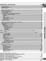
IMPORTANT
............................................................................
4-5
Display Formats ..................................................................................................................................
60-65
Appendix
Appendix
Appendix
Appendix
Appendix
A:
B:
C:
D:
E:
SAFEGUARDS
Bypassing the V-Chip Lock ...........................................................................................................
66
High Definition Inputs Connection Compatibility .......................................................................
67
Remote Control Programming Codes ..........................................................................................
68
Cleaning and Service .....................................................................................................................
69
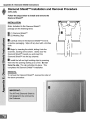
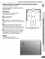
Diamond Shield Installation and Removal .............................................................................
70-71
Appendix F: Input Terminal Cover/Ventillation ..................................................................................................
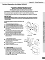
Appendix G Cabinet Separation Procedure .......................................................................................................
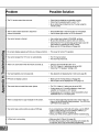
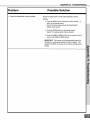
Appendix H: Troubleshooting .........................................................................................................................
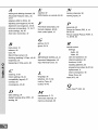
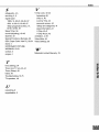
Index .................................................................................................................................................................
72
73
74-75
76-77
1. Read,Retain and Follow All Instructions
Read all safety and operating instructions before operating the TV. Retain the safety and operating instructions
for future reference. Follow all operating and use instructions.
2. Heed Warnings
Adhere to all warnings on the appliance and in the operating instructions.
3. Cleaning
Unplug the TV from the wall outlet before cleaning. Do not use liquid, abrasive, or aerosol cleaners.
can permanently damage the cabinet and screen. Use a lightly dampened cloth for cleaning.
Cleaners
4. Attachments
and Equipment
Never add any attachments and/or equipment without approval of the manufacturer as such additions may
result in the risk of fire, electric shock or other personal injury.
5. Water and Moisture
Do not use the TV where contact with or immersion in water is possible. Do not use near bath tubs, wash
bowls, kitchen sinks, laundry tubs, swimming pools, etc.
.
Accessories
Do not place the TV on an unstable cart, stand, tripod, or table. The TV may fall, causing
serious injury to a child or adult and serious damage to the TV. Use only with a cart, stand,
tripod, bracket, or table recommended by the manufacturer, or sold with the TV. Any mounting
of the TV should follow the manufacturer's instructions, and should use mounting accessories
recommended by the manufacturer.
An appliance and cart combination should be moved with care. Quick stops, excessive force,
and uneven surfaces may cause the appliance and cart combination to overturn.
7. Ventilation
Slots and openings in the cabinet are provided for ventilation and to ensure reliable operation of the TV and
to protect it from overheating. Do not block these openings or allow them to be obstructed by placing the TV
on a bed, sofa, rug, or other similar surface. Nor should it be placed over a radiator or heat register. If the
TV is to be placed in a rack or bookcase, ensure that there is adequate ventilation and that the manufacturer's
instructions have been adhered to.
8. Power Source
This TV should be operated only from the type of power source indicated on the marking label. If you are not
sure of the type of power supplied to your home, consult your appliance dealer or local power company.
9. Grounding or Polarization
This TV is equipped with a polarized alternating current line plug having one blade wider than the other. This
plug wilt fit into the power outlet only one way. If you are unable to insert the plug fully into the outlet, try
reversing the plug. If the plug should still fail to fit, contact your electrician to replace your obsolete outlet. Do
not defeat the safety purpose of the polarized plug.
10. Power-Cord
Protection
Power-supply cords should be routed so that they are not likely to be walked on or pinched by items placed
upon or against them, paying particular attention to cords at plugs, convenience receptacles, and the point
where they exit from the TV.
11. Lightning
For added protection for this TV during a lightning storm, or when it is left unattended and unused for long
periods of time, unplug it from the wall outlet and disconnect the antenna or cable system. This will prevent
damage to the TV due to lightning and power-line surges.
IMPORTANT
12.
SAFEGUARDS
Continued
Power Lines
An outside antenna system should not be located in the vicinity of overhead power lines or other electric light
or power circuits, or where it can fall into such power lines or circuits. When installing an outside antenna
system, extreme care should be taken to keep from touching such power lines or circuits as contact with
them might be fatal.
13. Overloading
Do not overload wail outlets and extension cords as this can result in a risk of fire or electric shock.
14. Object and Liquid Entry
Never push objects of any kind into this TV through openings as they may touch dangerous voltage points or
short-out parts that could result in fire or electric shock. Never spill liquid of any kind on or into the TV.
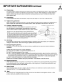
15. Outdoor
Antenna Grounding
If an outside antenna or cable system is connected to the TV, be
sure the antenna or cable system is grounded so as to provide
some protection against voltage surges and built-up static charges.
EXAMPLE 0 = ,'_.,_TEtHA JROLN-%U_
Section 810 of the National Electric Code, ANSI/NFPA No.
70-1984, provides information with respect to proper grounding of
the mast and supporting structure, grounding of the lead in wire to
an antenna discharge unit, size of grounding conductors, location
of antenna discharge unit, connection to grounding electrodes,
and requirements for the grounding electrode.
16. Servicing
Do not attempt to service this TV yourself as opening or removing covers may expose you to dangerous
voltage or other hazards. Refer all servicing to qualified service personnel.
17. Damage Requiring Service
Unplug the TV from the wall outlet and refer servicing to qualified service personnel under the following
conditions:
(a)
(b)
(c)
(d)
When the power-supply cord or plug is damaged.
If liquid has been spilled, or objects have fallen into the TV.
if the TV has been exposed to rain or water.
If the TV does not operate normally by following the operating instructions, adjust only those controls that
are covered by the operating instructions as an improper adjustment of other controls may result in damage
and will often require extensive work by a qualified technician to restore the TV to its normal operation.
(e) if the TV has been dropped or the cabinet has been damaged.
(f) When the TV exhibits a distinct change in performance - this indicates a need for service.
18. Replacement
Parts
When replacement parts are required, be sure the service technician has used replacement parts specified
by the manufacturer or have the same characteristics as the original part. Unauthorized substitutions may
result in fire, electric shock or other hazards.
19. Safety Check
Upon completion of any service or repair to the TV, ask the service technician to perform safety checks to
determine that the TV is in safe operating condition.
20.
Heat
The product should be situated away from heat sources such as radiators, heat registers, stoves, or other
products (including amplifiers) that produce heat.
at Mitsubishi Would Like to Thank You
To the Mitsubishi
Consumer:
Welcome to the wonderful and exciting world of digital television! We are honored that you
chose Mitsubishi as your premier home entertainment
partner. The development
team at
Mitsubishi understands that our customers demand and expect the very best. Mitsubishi
is founded on the core beliefs and philosophies that drive us to deliver products that are
both cutting-edge
and upgradeable.
While some televisions are destined for near-future obsolescence,
Mitsubishi's
HD-upgradeable
televisions are engineered with "future-ability."
Your television
continue to provide unparalleled
home entertainment
for years!
will
Whether this is your first Mitsubishi consumer electronics product or an addition to your
growing Mitsubishi family, we hope that this television will bring you and your family many
hours of enjoyment.
THE PROMISE
We will engineer and manufacture the upgrades necessary so the HD-Upgradeable
television you purchased today can be made compatible with near-future advances in
digital television and digital interconnectivity.
Specifically, we promise that you will be able
to have your television upgraded, at a reasonable cost, to include an off-air HDTV tuner, a
cable TV tuner (for unscrambled
programming),
an IEEE 1394 (FireWire®) connection, HAVi
system control, and 5C copy protection.
Part I: Introduction
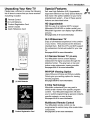
Unpacking Your New TV
Special Features
Please take a moment to review the following
list of items to ensure that you have received
Your new High Definition (HD) Upgradeable
bigscreen television has many special features
that make it the perfect addition to your home
entertainment system. A few of these special
features are described below.
everything
included:
[]
Remote Control
[]
(2) AAA Batteries
[]
Product Registration Card
Owner's Guide
Quick Reference Card
HD Upgradeable
With the use of an optional HDTV receiver
(Mitsubishi SR-I-ID400 or similar model) your
Mitsubishi bigscreen can display high definition
pictures.
See pages 20 & 21 for more information.
/
PonE_
16:9 Widescreen
TV
Enjoy a full theatrical experience in the comfort
of your home. View pictures as film directors
intended them. Both the DTV and DVD support
the widescreen format well-suited for your new
TV.
©@@
See pages 62-65 for more information.
4:3 Narrow Screen TV (VS-A50)
Your Mitsubishi narrow screen displays
widescreen liD signal source(s) through the
letterbox format. The gray bars on top and
_ MITSUBI_!
bottom make widescreen viewing possible.
See pages 60 & 61 for more information.
]
Remote Control
PIP/POP Viewing Option
Using Picture-in-Picture and Picture-outsidePicture give you exciting options for viewing
favorite programs.
[]
See pages 58-59 for more information.
(2) AAA Batteries
V-Chip Technology
Mitsubishi understands you may want to
shield certain viewers from specific program
content. Your Mitsubishi bigscreen will allow
you to restrict programming
by general contents,
specific contents, or even by time.
See pages 40-42 for more information.
Multibrand
Remote Control
Your Mitsubishi
remote control can be
programmed
[]
to control many other audio/video
components.
Product Registration
Card
See page 25 & 27 for more information.
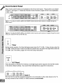
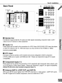
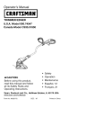
Front Control Panel
Many remote control buttons are duplicated on the front control panel These buttons are shaded
in Figure 1 and Figure 2 Please see Remote Control Functions, pages 54-58, for an explanation
of their usage
O
Figure 1. The ADJUST, ENTER, MENU, and CANCEL buttons may be used to access or navigate through the
screen menus•
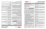
Figure 2. The ADJUST, ENTER, MENU, and CANCEL buttons may be used to access or navigate through the screen
menus (for models WT-A42 and WS-A48 only)•
o
T imer
During normal operation,
TV is Off
TV is Off
the timer light glows green when the TV is On
It does not glow when the
When the time is used to turn On at a specific time, the green timer light blinks while the
See TimerMenu,
pages 43-44 for timer setup instructions
@
..........
A/V Reset
Press this button to reset the A/V memory on all eight inputs (seven inputs for the VS-A50
to the factory default settings
See Audio/Video
Settings Menu, page 48 for instructions
.................................
ii _;'_
_
.......
_
...................
_:_=:_ _:_:_, _;_=_
_
...............................
.........
model)
_i
_
Input 3
This input can be used for convenient connection of a camcorder or other video device to the TV.
You may connect to the S-VIDEO or VIDEO terminal but not to both.
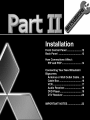
Part I1: Installation
Back Panel
1t/
Back
TV Rear Side
Panel
®®®
@ ®®®
@®®®
Pa_
®®®®®
®
[]
Monitor Out
The Monitor Output sends the TV audio and video signals (excluding
video) to an A/V receiver or other equipment.
[]
component
video or DTV
Inputs 1-2
These inputs can be used for the connection
of a VCR, Super VHS (S-VHS) VCR, laser disc player,
or other A/V device to the TV. With each input, you may connect to the S-VIDEO or VIDEO
terminal
[]
but not to both.
DTV Input
This input is used to connect a DTV receiver and can be configured
(YPbPr), RGB sync on green, and RGB plus H&V.
compatibility.
[]
Component
for HDTV component
Please see Appendix
B, page 67, for signal
Inputs 1-2
-Ihese inputs can be used for the connection of A/V equipment with component video outputs, such
as a DVD player or Video Game System. Please see Appendix B, page 67, for signal compatibility.
(Model VS-A50
[]
[4:3] only includes
Component
Input 1.)
Antenna (ANT-A, LOOP OUT, and ANT-B)
ANT-A and ANT-B receive signals from VHF/UHF antennas or a cable system.
the ANT-A signal out to another component, such as a cable box or VCR.
LOOP OUT sends
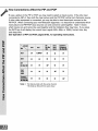
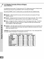
How Connections
Affect the PIP and POP
To see a picture in the PIP or POP, you may need to select an input source. If the only input
connected is ANT-A, then both the main picture and the PIP/POP will be from that input source.
If other video equipment is connected, you may be able to view these input sources as the
PIP/POP. When connecting your new Mitsubishi bigscreen, it is important to understand which
main picture and PIP/POP input sources can and cannot be used together. Table 1 shows
which inputs can and cannot be used together and the limitations they may have. If you press
the INFO key it will display the current Input, signal (480i, 480p, or 1080i), format, time, day
and sleep time.
See Operation of PIP and POP, pages 58-62, for operating instructions.
_
O_
O_
OK
OK
O_
OK
OK
OK
Table 1. *No Side-by-Side with the same channel
**No Side-by Side with the same inpuL
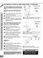
Part I1: Installation
Connecting an Antenna, Wall Outlet Cable, or Cable Box
1V I_'k
ANT-A
F_
Separate
_,anel (l_tai_e_ V_)
UHF and VHF Antennas
(Figure 1)
[]
Connect the UHF and VHF antenna
to the UHFNHF combiner.
[]
Push the combiner
leads
_4_r
_
.......................................
,_
onto ANT-A on the TV
back panel.
UHF/VHF
combiners
are not provided
with the TV. They are available
electronic
stores.
Figure I. Connecting separate UHF and VHF antennas.
Note: See page 5 for Outdoor Antenna Grounding
at most
Twin Lead Antenna, Coaxial Lead
Antenna, or Wall Outlet Cable
For antenna with twin flat leads (Figure 2)
[] Connect the 300ohm twin leads to the
transformer.
[]
Push the 75ohm side of the transformer
..................
onto ANT-A on the TV back panel.
300ohm to 75ohm matching transformers
are not provided with the TV. They are
available at most electronic stores.
Figure 2. Connecting twin lead antenna, coaxial lead
antenna, or wall outlet cable.
Note: See page 5 for Outdoor Antenna Grounding
For cable or antenna with coaxial lead (Figure 2)
[]
Connect
the incoming
the TV back
cable
to ANT-A
,_y
_ :
&
IANT'A
on
panel.
1!/_
pt_el (O_talled V]_}
LOOP
OUT
ANT-B
Cable Box
(Figure 3)
H
[]
[]
[]
Connect the incoming cable to ANT-A on
the TV back panel.
Connect two coaxial cables as follows:
One from LOOP-OUT on the TV back panel
to IN on the cable box back panel.
One from OUT on the cable box back panel
to ANT-B on the TV back panel.
H
Figure 3. Connecting the cable box.
Note: See page 5 for Outdoor Antenna Grounding
Part I1: Installation
Antennas or Wall Outlet Cable
Connecting a VCR
(Figure 1)
[]
[]
LOOP
OUT
ANT=A
AMT_B
@ @
[]
[]
;
@
Figure 1. Connecting
table.
Connect the incoming cable to ANT-A on
the TV back panel.
Connect two coaxial cables as follows:
One from LOOP-OUT on the TV back panel
to ANTENNA IN on the VCR back panel.
One from VCR back panel ANTENNA OUT
to ANT-B on the TV back panel.
Now complete Figure 3, steps 1-2.
®
VCR with antennas or wall outlet
Cable Box
(Figure 2)
[]
TV
back
ANT-A
panel
(Deta._d v(ew)
LOOP
OMT
A_T_B
Connect the incoming cable to ANT-A on
the TV back panel.
m
-.. Connect three coaxial cables as follows:
[]
One from LOOP-OUT on the TV back panel
to IN on the back of the cable box.
[]
One from OUT on the back of the cable
box to ANTENNA IN on the VCR back
panel.
[]
Figure 2. Connecting VCR with cable box.
[]
Composite Video with Audio or
S-Video with Audio
@@
(Figure 3)
[]
@@
i
_41_rRFt3_F
i
i>J_
One from ANTENNA OUT on the VCR back
panel to ANT-B on the TV back panel.
Now complete Figure 3, steps 1-2.
Connect a video cable from VIDEO OUT on
the VCR back panel to VIDEO INPUT-1 or
INPUT-2 on the TV back panel.
.."q If you have an S-VHS VCR, follow the
same steps using the S-Video terminals
the VCR and TV (in place of the composite
terminals). You may connect to the
S-VIDEO or VIDEO terminal but not to
both.
Figure 3. Connecting the VCR Audio/Video.
[]
Connect
a set of audio cables from AUDIO
OUT on
INPUT-1
The red
channel
the VCR back panel to AUDIO
or INPUT-2 on the TV back panel.
cable connects to the R (right)
and the white cable connects to
the L (left) channel.
If your VCR is mono
(non-stereo), connect only the white (left)
cable.
i!qO;
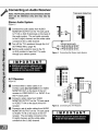
Connecting an Audio Receiver
Stereo Audio System
(Figure 1)
[]
Connect the audio cables from AUDIO
MONITOR OUTPUT on the TV back panel
to TV IN or AUX IN terminals on the back of
the audio system. The red cable connects
to the R (right) channel, and the white cable
connects to the L (left) channel.
[]
[]
Turn off the TV's speakers
through the A/V
SETTINGS Menu, page 48.
Set the audio system's input to the TV
or AUX position to hear the TV's audio
through your stereo system.
Figure 1. Connecting the Stereo Audio System.
®l®®
A/V Receiver
@
@@
(Figure 2)
@
@@
[]
[]
[]
Connect either a video cable or an
S-Video cable (but not both) from VIDEO
MONITOR OUT on the back of the A/V
receiver to VIDEO INPUT-1 or INPUT-2 on
the TV back panel.
Connect a video cable from VIDEO
MONITOR OUTPUT on the TV back panel
to VIDEO TV IN on the back of the A/V
receiver.
Connect a set of audio cables from AUDIO
MONITOR OUTPUT on the TV back panel
to AUDIO TV IN on the back of the A/V
receiver. The red cable connects to the
R (right) channel, and the white cable
connects to the L (left) channel.
®®
Figure 2. Connecting the A/V Receiver.
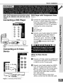
Part I1: Installation
WARNING:
N_teiThe_yba_kpanel_nd_o_ne_t!QnsshQ_ DVD Player with Component
herb b_
for _efere_cb
_!_
a_d may _r_
by
Video
(Figure 1)
Connect the Component Video cables from
(YCbCr or YPbPr) VIDEO OUT on the
back of the DVD player to COMPONENT-1
or COMPONENT-2
on the TV back panel,
Connecting a DVD Player
I
matching
[]
[]
[]
...
the correct components:
YtoY
CborPbtoPb
CrorPrtoPr
Connect a set of audio cables from AUDIO
OUT on the back of the DVD player to
COMPONENT
AUDIO Input 1 or 2 on
the TV back panel. The white cable []
connects
to the L (left)channel,
red cable [] connects
channel.
u
| M
Figure 1. Connecting a DVD Player with Component
Video.
P Q
and the
to the R (right)
RTA
_T
Connecting an S-Video
Device
'IV back _n_l
_led_V_,e,u)
Other S-Video Device
(Figure 2)
@@
[]
@
@
Connect an S-Video cable from VIDEO OUT
on the device back panel to VIDEO INPUT-1
or INPUT-2 on the TV back panel.
[]
Connect
OUT on
INPUT-1
•The red
channel
a set of audio cables from AUDIO
the device back panel to AUDIO
or INPUT-2 on the TV back panel.
cable connects to the R (right)
and the white cable connects to
the L (left) channel.
• If your S-Video Device is mono (nonstereo), connect only the white (left) cable.
Figure 2. Connecting S-Video Device.
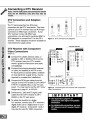
DTV Connectors
and Adaptors
(Figure 1)
The TV back panel has five RCA-type
connectors for the DTV connection.
The back
panel of your DTV receiver may use RCA-type
connectors or BNC-type connectors.
If your
DTV receiver comes with BNC type
connections, you will need to purchase BNC to
RCA adaptors to connect the TV to the DTV
receiver. These adaptors should be available at
most electronic supply stores.
_..
Figure I. DTV connectors and adaptors.
DTV Receiver with Component
Video Connections
®
®
(Figure 2)
[]
Connect the outside antenna cable, or
satellite to ANT or SATELLITE IN on the
DTV receiver (see your DTV receiver
owner's guide for instructions and cable
[]
[]
compatibility).
Connect the incoming terrestrial antenna
or cable (not satellite) to ANT-A on the
TV back panel (a coaxial splitter, available
at most electronic supply stores, may be
required to complete this installation).
_
_N_.
_
Connect the RCA-type cables from the
outputs on the DTV receiver to DTV INPUT
Y/Pb/Pr or Satellite/Box
on the TV back
panel. You may need to set the DTV Input
Assignment, page 31, to Y/Pb/Pr.
[]
®
Connect the L (left) and R (right) audio
cables from the DTV receiver to DTV
AUDIO on the TV back panel.
To utilize the benefits of a digital
A/V receiver, connect your DTV receiver's
digital audio out to a digital input on your
digital A/V receiver. Component 1 and 2
may also be used for 1080i component.
Figure 2. Connecting the DTV receiver with component
Video Connections.
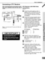
Part I1: Installation
Connecting a DTV Receiver
DTV Receiver with RGB Video
Connections
(Figure 1)
[]
Connect the outside antenna, cable, or
satellite to ANT or SATELLITE IN on the
DTV receiver (see your DTV receiver's
owner's guide for instructions and cable
compatibility).
[]
Figure 1. Connecting the DTV receiver with RGB video
connections.
Connect the incoming terrestrial antenna
or cable (not satellite) to ANT-A on the
TV back panel (a coaxial splitter, available
at most electronic supply stores, may be
required to complete this installation).
Connect the RGB cables from the DTV
receiver to the TV back panel as listed
below (if your DTV receiver uses BNC-type
cables, use the adaptors shown in
Figure 1, page 20):
DTV Receiver
TV Back Panel
_L_ G
(green)
B (blue)
=
=
Y
Pb
[]
=
Pr
R (red)
If the DTV receiver has outputs for H
and V sync, connect as listed below (DO
NOT connect if DTV receiver uses "Sync
on Green"):
H (vertical
(horizontalsync)
V
sync)
[]
=
=
H
V
Connect the L (left) and R (right) audio
cables from the DTV receiver and to DTV
AUDIO on the TV back panel.
m
To utilize the benefits of a digital
A/V receiver, connect your DTV receiver's
digital audio out to a digital input on your
digital A/V receiver.
You may need to setup the DTV (See Input
Assignment, page 31) to RGB.
Part I1: Installation
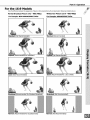
Warning:
Do not leave stationary, PIP/POP, or letterbox images on-screen
for extended periods of time. Mix the types of pictures shown.
Uneven picture tube aging is NOT covered by your warranty.
The normal use of a TV should include a
mixture of TV picture types. The most
frequently used picture types should fill the
screen with constantly moving images rather
than stationary images or patterns. Displaying
the same stationary patterns over extended
periods of time or displaying the same
stationary pattern frequently may leave a subtle
but permanent ghost image. To avoid this, mix
your viewing pattern. Do not show the same
stationary image for more than 15% of your
total TV viewing in any given week. Display
constantly moving and changing
images that fill the screen whenever possible.
This projection TV uses picture tubes to project
the image to the screen. All picture tubes
age with use. As they age, their light output
is gradually reduced. Normal TV pictures fill
the screen with constantly changing images.
Under these conditions, picture tubes age at
an even rate across the entire screen. This
maintains a TV picture that is evenly bright
over the whole screen. Stationary images or
images that only partially fill the screen
(leaving black or colored bars to fill the screen),
when used over extended periods of time or
when viewed repeatedly may cause uneven
aging of the phosphors and leave subtle ghosts
of the stationary images in the picture.
Still or stationary images may be received
from broadcasters, cable channels, satellite
channels, DVD discs, video tapes, laser
discs, on-line services, web/Internet
searching devices, video games, and digital
TV tuner/converter boxes. Examples of these
types of images can be, but are not limited to
the following:
Letterbox top/bottom black bars:
shown at the top and bottom of the TV
screen when you watch a widescreen
(16:9) movie on a standard (4:3) TV.
._ Side bar images: solid bars shown
on each side of an image when
watching a standard (4:3) program on
a widescreen (16:9) TV.
Stock-market report bars: ticker
running at the bottom of the TV
screen.
..."qShopping channel Iogos & pricing
displays: bright graphics that are
shown constantly or repeatedly in the
same location.
._'_Video game patterns and scoreboards
._'_ Bright station Iogos: moving or
low-contrast graphics are less likely
to cause uneven aging of the picture
tubes.
Online (Internet) websites: or any
other
stationary or repetitive
computer style images.
Closed Captioning
Use of the Remote Control with Other A/V Products
To Program the Remote to Control
Other Brands of Audio and Video
Products:
(Figures 1-5)
[]
Move the slide switch at the top of the
remote to the product you want to control.
[]
Press and hold the POWER
remote control.
[]
Enter the first three digit code listed for your
equipment, and then release the POWER
button on the remote control.
[]
[]
button on the
Point the remote control to the equipment
and press the POWER button.
Note: If the equipment responds, the remote
control is properly programmed to operate
the equipment.
If the equipment does not
respond, repeat steps 2-4 with the next
three digit code listed in step 3 for your
equipment.
[]
Figure 2. Programming the remote to control your
satelfite receiver.
[]
?o rew_w _
_
_nu=r_
Figure 1. Programming the remote to controlyour
cable
box.
Figure 3. Programming the remote to control your VCR.
Part II1: Setup
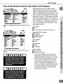
Use of the Remote Control with Other A/V Products
[]
After entering the correct codes in each
position of the remote control, use the slide
switch to select which product will respond
when an operational button is pressed. If you
enter a code from the AUDIO chart while the
slide switch is set to TV, the volume and mute
functions change to match the A/V receiver.
This is useful when using an A/V receiver with
the TV all the time. In all other cases, only
one of the below devices is allowed for each
slide switch position.
Figure 4. Programming the remote to control your DVD/
LDP.
+i+i#i_
TV position:
-_ TV
III
..,"_ A/V receiver
(volume and mute only)
Cable/DBS/DTV
position:
Cable box
Satellite receiver
DTV receiver
ii!i!i!ii
VCR position:
VCR
iii!i_i!_
DVD position:
DVD
LD Player
Figure 5. Programming the remote to control your A/V
receiver.
Audio position:
A/V receiver
Mitsubishi
CD player
If you have a Mitsubishi
A/V receiver,
the
audio position may be used in conjunction
with select Mitsubishi CD players. Your audio
position must be programmed
to either 010
or 011. Plug the CD player power cord into
a switched outlet on the back ofyourA/V
receiver, Pressing the POWER button tums
On the A/V receiver, along with the CD player.
In the audio position, for some CD players,
the transport controls (FF, Play, Rew, etc.)
operate
iiii!
iiii!ii!_
!++
iiii!iiiiiiiii
the CD player.
iiiiiiii_i#iiii#!i
.....
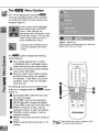
° Menu System
Your TV has Mitsubishi's
on-screen
on-screen
changes
exclusive
,flmroint
°
operating system, which provides
information for menu choices and
(Figure 1).
A picture (icon) will be highlighted
when selected with the ADJUST
arrows. When selected, the
appropriate menu will appear or start
an automatic function.
You may then
make changes within the menu or
access available sub-menus.
A square button indicates that you
may make changes to the menu
screen.
The J_iloiilr
Figure 1. MAIN menu:
The first screen that appears when you press the
MENU button from your remote.
system includes the following
special features:
-,,='_The currently selected icon or button
is highlighted with a rectangular yellow
outline and the text color will be yellow.
On-screen instructions provide complete
menu choice information.
-,,='_Some on-screen menu options must be
set before other options are available.
For example, 'Timer Menu" will only be
possible if "Clock Time" and "Set Day"
have been set.
The following
buttons on your remote control
helps you to navigate
within the Pl_iloiilr' system
D
(Figure 2):
[]
[]
[]
[]
[]
[]
[]
[]
ADJUST A or v to select the menu item
you want to change.
ADJUST I_ to move to the setting field.
ADJUST A or v to change the settings.
ADJUST q to move back to the menu item.
ENTER to enter into a menu, start an
automatic function, or select a checkbox.
CANCEL to clear a setting, or stop an
automatic function.
MENU to move back one menu screen at
a time.
HOME to exit all menus and return to TV
viewing.
MITSUBISH|
Figure 2. These buttons are used for navigation within
the i_L_,_r on-screen operating system.
Part II1: Setup
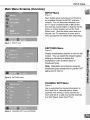
Main Menu Screens (Overview)
SETUP Menu
(Figure 1)
Basic (initial) setup instructions and functions
are available through the SETUP submenu
screens. You can memorize channels, turn
the TV input connections On or Off, set the
time and day, select English or Spanish for the
menus or screen display, and set the Front
Button Lock. (Use the setup menu when you
relocate the TV, experience a power loss or
when accessories are added after initial setup).
Figure 1. SETUP menu
CAPTIONS
Menu
(Figure 2)
Display broadcasted captions or text on the
screen. You can select the closed caption
setting by choosing to display the
background color as either black or
translucent gray.
Note: Mitsubishi recommends using the
translucent gray background to prevent CRT
aging and/or burn-in.
Figure 2. CAPTIONS menu
CHANNEL
EDIT Menu
(Figure 3)
Use to customize
the channel
information
for
Ant-A and Ant-B. Manually add or delete
channels from memory, name channels for
Ant-A and Ant-B, or add your favorite channels
to a SQV (Super Quick View TM) list.
Figure 3. CHANNEL EDITmenu
(ANTENNA)
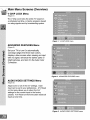
Main Menu Screens (Overview)
V-CHIP LOCK Menu
(Figure 1)
The V-Chip Lock locks the entire TV based on
a scheduled set time, or blocks programs based
on rating signals sent by broadcasting system.
Figure 1. V-CHIP LOCK menu
ADVANCED
FEATURES
Menu
(Figure 2)
Set your TV to turn On automatically,
converge (align) the three main colors,
display a blue screen when viewing an input
with no signal, enhance the darker parts of
bright pictures, and turn On the Auto Color
Correction.
Figure 2. ADVANCED FEATURES menu
AUDIO/VIDEO
SETTINGS
Menu
(Figure 3)
Adjust some or all of the A/V settings. Each
input can be set to your preferences.
A/V Reset
on the menu allows you to return the A/V
settings for the current input to the factory
presets. A/V Reset on the front button resets all
inputs at one time.
Figure
3. AUDIO/VIDEO
SETTINGS
menu
Part II1: Setup
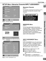
SETUP Menu: Memorize Channels/INPUT
Memorize
ASSIGNMENT
Channels
(Figure 1)
This selection memorizes the channels your TV
can receive and skips the unused or weak
channels.
IMPORTANT
Figure 1. Memorize Channels
MEMORIZE
Menu
(Figure 2)
You can stop memorization at any time by
pressing CANCEL. Channels memorized prior
to pressing CANCEL will stay in memory.
After channels are memorized, you may select
memorized channels in ascending or
descending order by pressing the CHANNEL
button on the remote control.
Figure 2. MEMORIZE menu (Memorize Channels
in memory)
INPUT ASSIGNMENT
Menu
(Figure 3)
INPUT ASSIGNMENT turns off unused inputs,
turns them on again, or changes the name of
the input. If you turn an input Off, it will be
skipped when you press the INPUT button on
the remote control.
Input choices
are:
Antenna-A or Antenna-B: On or Off.
DTV: YPbPr, RGB, or Off.
INPUT-l, INPUT-2, INPUT-3:
Cycle through a list of preset names,
Off.
COMPONENT-1
Cycle through
Figure3.
INPUT ASSIGNMENT
menu
or
or COMPONENT-2:
a list of preset names, or Off.
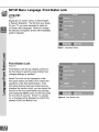
SETUP Menu: Language/Front
Button Lock
Language
(Figure 1)
Display the on-screen menus in either English
or Spanish (EspaSol). The first time your power
On your TV, you were requested to select an
on-screen menu language. When you change
the selection to Espa_ol, all text will immediately
switch to Spanish.
Figure 1. Language/ Idioma
Front Button Lock
(Figure 2)
Front Button Lock lets you disable controls on
the front panel to prevent young children from
changing settings by accident.
Select On to lock out the operations of the
front panel button and select Off to restore the
operations of the front panel buttons. If the
front panel buttons have been locked and you
misplace the remote control, you can restore the
function of the front panel buttons by pressing
and holding the MENU button on the front panel
for more than 8 seconds. If the TV is already
on, a message will be displayed to confirm the
release of the Front Button Lock.
Figure 2. Front Button Lock
Part II1: Setup
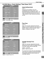
CLOCK Menu: Clock Setting / Time Zone / D.S.T.
Clock Setting (Auto)
(Figure 1)
Setting the Clock Setting to Auto will
automatically set the day and time using
Extended Data Service (XDS) time data. This
data is automatically
retrieved when tuned to
a PBS channel or other channels carrying this
service.
m
Figure 1. Clock Setting (Auto)
Time Zone
(Figure 2)
When Auto has been selected
for the Clock
Setting, you need to select the correct time zone
(Atlantic, Eastern, Central, Mountain, Pacific,
Alaska, or Hawaii) for your area.
Figure 2. Time Zone
iii!ii
Daylight Savings Time
(Figure 3)
When Auto has been selected
for the Clock
Setting, you need to select the Daylight Savings
Time (DST) option that your state uses.
Applies = uses DST
Ignore = does not use DST
The clock time and day will be set automatically
Figure 3. Daylight Savings Time
after tuning to a channel carrying the Extended
Data Service (XDS) time data (usually your
local PBS channel).
Clock Menu: Clock Time/Set
Day
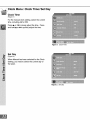
Clock Time
(Figure 1)
For the manual clock setting,
time, including AM or PM.
select the current
Press A or v to slowly adjust the time. Press
and hold A or v to quickly adjust the time.
Figure 1. Clock Time
Set Day
(Figure 2)
When Manual
has been selected for the Clock
Setting, you need to select the current day of
the week.
Figure 2. Set Day
Part II1: Setup
CAPTIONS Menu: Closed Captions
CAPTIONS
Menu
(Figure 1)
Broadcasters
can send either Standard
or Text
closed captioning.
Standard closed captioning
follows the dialogue of the characters on-screen
and displays in a small section of the screen.
Text closed captioning often contains
information such as weather or news and covers
a large portion of the on-screen program. Your
TV can decode four different standard and four
Figure 1. CAPTIONS menu
different text closed captioning signals from
each TV station. However, each TV station may
broadcast only one or two closed captioning
signals, or none at all.
Within the CAPTIONS menu, you can turn On
or Off the closed caption decoder, select the
type of captions or text, and choose black or
translucent gray as the background color for the
closed caption area.
Closed Captions
(Figure 2)
The TV can display one of the following:
-,,
CC1, CC2, CC3, or CC4: Standard
closed
captioning signals.
='_
Text1,
Text2, Text3, or Text4: Text closed
m
Figure 2. Closed Captions
captioning signals.
On if mute: Closed captions when
mute. When selected, the standard closed
captioning signal (CC1) will turn on/off by
pressing the MUTE button on the TV
remote control.
Off: No closed captions.
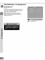
CAPTIONS Menu: CC Background
CC Background
(Figure 1)
To make the closed captions easier to read, you
can choose to display the background color as
either black or translucent gray.
Note: Mitsubishi recommends
using the
translucent gray background to prevent CRT
aging and/or burn-in.
Figure 1. CAPTIONS menu
|MPORTANT
Part II1: Setup
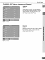
CHANNEL EDIT Menu: Antenna and Channel
Antenna
(Figure 1)
Select Ant-A or Ant-& For each antenna,
you can add or delete channels in memory,
name channels, and add channels to the
SQV (Super Quick View
TM)
list.
Figure 1. Antenna
Channel
(Figure 2)
Select the channel you want to add or delete
from memory, name, or add to the SQV
(Super Quick View TM) list.
Figure 2. Channel
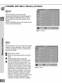
CHANNEL EDIT Menu: Memory and Name
Memory
(Figure 1)
After all available
channels
have been
memorized with Memorize Channels (page 31 ),
weaker channels viewed with Ant-A or Ant-B
can be added and unwanted channels can be
deleted.
Use the CHANNEL button on the remote control
to view memorized channels.
Figure 1. Memory
Name
(Figure 2)
Channels shown on Ant-A or Ant-B can be given
names (up to four characters).
After you enter
a name, it will appear on the TV screen next to
the channel number.
[]
Select Ant-A or Ant-B.
[]
Select the memorized
name.
[]
Press ADJUST
[]
underline highlighted
in the Name field.
Use ADJUST ,= or v to select letters A-Z,
channel you want to
until you see the
numbers 0-9, and/or symbols (!.&'/:*- and
blank) for each character of the name you
would like for the selected channel. Press
ENTER
after choosing
each
letter and
after the name is complete. If you want to
change your selection while on the option
field, use CANCEL to delete the current
character. You will move one position back.
If you press CANCEL while at the first
character, the entire name will be deleted.
Figure 2. Name
Part II1: Setup
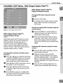
CHANNEL EDIT Menu: SQV (Super Quick View TM)
SQV (Super Quick View
Using The Remote Control
Changing
control:
TM)
SQV banks using the remote
[]
Press the SQV button.
[]
To change memory banks, press a number
button within 5 seconds of pressing the
SQV button.
Viewing and Adding SQV channels
remote control:
using the
Figure 1. SQV (Super Quick View TM)
[]
Use the CHANNEL or number buttons to
select the channel you want to add to the
current SQV memory bank.
[]
Press and hold the SQV button for about
3 seconds. When "SQV" and the memory
bank number appear under the channel
number, the channel has successfully been
added.
SQV (Super Quick View TM)
Using
The Menu
Screen
(Figure 1)
SQV (Super Quick View TM) allows you to put
together a list of your favorite channels from
Ant-A and Ant-B. You can store up to 6
channels in each of the 9 different memory
banks. Once you have added a channel to
the SQV memory, "SQV" will appear under the
channel number on the TV screen.
Changing
SQV channels
the menu:
[]
and banks using
Removing
control:
Press the SQV button repeatedly
see the desired channel.
[]
While the channel
[]
Press
& or v when at SQV in the menu
to select the SQV memory
to modify.
[]
bank you wish
Press ENTER to add (On) or delete (Off)
the current channel from the SQV memory
bank that you have selected.
until you
number and SQV
indicator are still displayed on the screen,
press the CANCEL button. If the CANCEL
button is not pressed before the SQV
indicator disappears, the channel will not be
removed.
control to select the channel you wish to
add or delete from a SQV memory bank.
Press libwhen at SQV in the menu to move
the selector to the On/Off choice.
using the remote
[]
Press & or v when at Channel in the menu
or use the CHANNEL button on the remote
[]
SQV channels
[]
When the SQV indicator disappears, the
channel has successfully been removed.
:HIP Menu: V-CHIP LOCK
Entry to the V-CHIP
LOCK
(Figures 1-2)
The first time you select V-CHIP LOCK from the
MAIN menu or after you have canceled your
passcode, you will see the screen shown in
Figure 1. Use the number buttons on the
remote control to input a new four-digit
passcode, then press ENTER. You can
delete a character and move back one
character by pressing CANCEL, or leave
the passcode screen by pressing MENU or
HOME. The next time you select V-CHIP
LOCK from the MAIN menu, input your
passcode as shown in Figure 2 (Note: Text
changes from "a new" to "your" passcode).
Figure 1. First time entry to the V-CHIP LOCK
V-CHIP LOCK
(Figure 3)
Figure
2. Re-entry
to the V-CHIP LOCK
You can Block or Allow programs based upon
rating signals sent by the broadcasting station.
The factory preset for TV Ratings is TV-PG
(Parental Guidance) allowing only programs
rated TV-PG or lower. The factory preset
for Movies is PG, allowing only movies rated
PG or lower.
Figure3.
V-CHIP LOCKmenu
Part II1: Setup
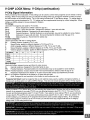
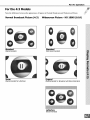
V-CHIP LOCK Menu: V-Chip (continuation)
V-Chip Signal Information
When provided by the broadcaster, V-Chip ratings can be used to control which programs can be viewed or will be
blocked. When V-Chip ratings are sent, you will see the ratings when you change the channel or when you press
the INFO button on the remote control. The V-Chip rating includes both TV and Movie ratings. TV ratings apply to
programs and movies developed for TV. TV ratings can have supplemental blocking by content categories. Movie
ratings use MPAA ratings for movies released in theaters.
TV Ratings:
Used with TV programs and made for TV movies.
TV-Y
Youth, designed for children under the age of 7.
TV-Y7
Youth, 7 years old and older. Designed for children 7 years old and older.
TV-G
General Audience. Designed for the entire family to view.
TV-PG
Parental Guidence. Parental Guidence is recommended, may not be suitable for some children.
TV-14
Adolescent 14 years old and older. Not recommended for children under the age of 14.
TV-MA
Mature Audience. Recommend for adults only.
Content Categories:
Used in association with the TV ratings above.
FV
Fantasy Violence- applies to TV-Y7 only.
D
Sexual Dialog- applies in different degrees to TV-PG and TV-14.
L
Adult Language- applies in different degrees to TV-PG, TV-14, and TV-MA.
S
Sexual Situations- applies in different degrees to TV-PG, TV-14, and TV-MA.
V
Violence (graphic or realistic)- applies in different degrees to TV-PG, TV-14, and TV-MA.
TV _ng
_
D
L
S
Y
W#G
×
×
×
x
"tv-14
x
x
x
x
x
X
X
"rst-y
"r_-Y7
W-UA
x
Movie Ratings:
Used with theater released movies and direct-to-video movies.
G
General Audience- Designed for the entire family to view.
PG
Parental Guidence- Parental Guidence is recommended, may not be suitable for some children.
PG-13 Parental Guidence 13 years old and older- Not recommended for children under the age of 13.
R
Restricted- Restricted in the theater to 17 years old and older unless accompanied by an adult.
N0-17 No Children- Restricted in the theater to 18 years old and older.
X
Adult- Designed for and restricted in the theater to adult audiences only.
Programs Not Rated: Used for programs that are not rated like news, sports, weather, emergency bulletins, or
movies such as those prior to or without MPAA Ratings. This does not include programs without V-Chip signals.
When you select a TV or Movie rating, you are selecting the highest level of program that will be allowed to be
viewed. As an example, if you select TV-PG, you are allowing programs rated TV-Y, TV-Y7, TV-G and TV-PG to
be seen and blocking programs rated TV-14 and TV-MA. If you select a movie rating of PG-13, you are allowing
movies rated G, PG and PG-13 to be seen and blocking movies rated R, NC-17, and X. When you select a TV
Content category, you wilt block atl TV programs that have the same content category listing. As an example,
if you select to block V (Violence) at the TV-14 level, you will atso block any program that has the V category
listing at the TV-PG rating level as well.
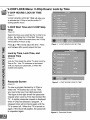
:HIP LOCK Menu: V-Chip Hours/Lock
:HIP HOURS/LOCK
by Time
BY TIME
(Figure 1)
V-CHIP HOURS/LOCK
BY TIME will allow you
to activate the V-Chip or lock the entire TV
during specific hours.
V-CHIP Start Time and V-CHIP Stop
Time
(Figure 2)
Select
Active.
V-Chip
will be
the times you would like the V-Chip to be
By setting the V-Chip Start Time and
Stop Time to the same time, the V-Chip
active 24 hours a day.
Press A or v to slowly adjust the time.
Press
Figure 1. V-CHIP HOURS/LOCK
BY TIME
and hold ,= or v to quickly adjust the time.
Lock by Time, Lock Time, and
Unlock Time
(Figure 2)
Lock by Time locks the entire TV when Lock by
Time is On. Your TV continues to be locked
until you input your passcode,
locked time expires.
or when the
Passcode Screen
Figure 2. V-CHIP HOURS/LOCK
(Figure 3)
To view a program blocked by V-Chip or
watch the TV blocked by Lock by Time,
you must enter your four-digit passcode.
The figure to the right shows the passcode
request when Lock by Time has blocked the
TV. A similar passcode request is displayed
when V-Chip has blocked a program. A
released block will not block again until the
TV is turned off. When the TV is turned on
again, if the block still applies, the passcode
is requested again.
Figure 3. Passcode
Screen
BY TIME
Part II1: Setup
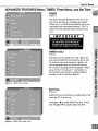
ADVANCED FEATURES Menu: TIMER, Timer Menu, and
TIMER
(Figure 1)
The timer will automatically
turn the TV on (if
it is off) at the time you schedule and select.
When Ant-A or Ant-B is the selected input, you
may select any memorized channel. The TV
will tune to this channel when the timer turns
it on.
Figure 1. ADVANCED FEATURES menu (Timer)
TIMER menu
(Figure 2)
iii!_ili_!iii
F
The timer can be turned On or Off. When On,
you need to select the time and the day to turn
On and the input and channel to display. At
your preselected time, the timer will turn the
TV on and a message will be displayed, "Press
a key for the TV to stay on." Any button on
the remote control must be pressed within 5
minutes or the TV will turn itself off.
Figure 2. TIMER menu (Timer)
Set Time
(Figure 3)
Select the hour and minute, including
when the TV is to turn on.
AM or PM,
Press A or v to slowly adjust the time. Press
and hold A or v to quickly adjust the time.
Figure 3. TIMER menu (Set Time)
iii!_ii_i_ii
.3ED FEATURES Menu: Set Day, Input, and Channel
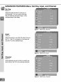
Day
(Figure 1)
Select the days that the TV will turn on
automatically.
You can select Everyday,
Mon-Fri (Monday through Friday), or the
individual days of the week.
Figure 1. TIMER menu (Set Day)
Input
(Figure 2)
Select the input to use when the timer turns on
the TV. If the TV is already on, the timer will
turn the TV to this selected input.
Figure 2. TIMER menu (Input)
Channel
(Figure 3)
If the selected input is for Ant-A or Ant-B, the
timer will turn the TV to the selected channel.
Figure 3. TIMER menu (Channel)
Part II1: Setup
ADVANCED FEATURES Menu: CONVERGENCE
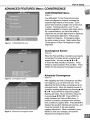
CONVERGENCE
Menu
(Figure 1)
Your Mitsubishi TV has three picture tubes
which are aligned to properly converge the
projected light beams on the screen. Each
picture tube projects a single color of red, blue
or green. During production, your TV was
carefully adjusted to properly align these colors.
As a special feature, you have the ability to
adjust the red and blue light beams in reference
to the fixed green light beam. This process
is called convergence.
Convergence aligns
the entire screen at once. Select either Red
Figure 1. CONVERGENCE
menu
Convergence
alignment.
or Blue Convergence
Convergence
to begin
Screen
(Figure 2)
When the Red and Blue crosshairs are properly
converged, the center-screen crosshairs will
appear white. You can use A, v, q, or b
to move the Red and Blue crosshairs.
Press
VIDEO to switch between Red and Blue. Press
AUDIO for the Advanced
Convergence
screen.
Advanced Convergence
Figure 2. Convergence screen
(Figure 3)
After adjusting the Red Convergence and Blue
Convergence, you can fine-tune your TV by
adjusting the Red and Blue convergence at 64
individual points. Move the flashing bracket to
a position needing adjustment by pressing A, v
q, or lb. Press ENTER to select the position
(flashing will stop). Move the Red or Blue line
by pressing A, T, q, or IP. Press VIDEO to
switch between the Red and Blue lines. A
Figure 3. Advanced Convergence screen
position is properly converged when all three
lines combine to appear white. Press ENTER to
deselect the position (flashing will resume), and
move the brackets to the next position
needing adjustment.
When completed, press
MENU to save your changes, and exit the
Advanced Convergence screen.
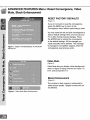
ADVANCED FEATURES Menu: Reset Convergence,
Mute, Black Enhancement
Video
RESET FACTORY DEFAULTS
(Figure 1)
If you do not want to reset the convergence,
press the MENU key to return to the
Convergence menu without performing a reset.
Figure I. RESET CONVERGENCE
DEFAULTS
TO FACTORY
You may reset the red and blue convergence to
factory default settings when you first use your
TV or after making manual changes. Press
the ENTER key to restore the convergence
to the default settings. All the changes you
made manually will be deleted. The message
"Convergence Completed" appears when the
convergence reset process ends.
Video Mute
(Figure 2)
Video Mute lets you display a blue background
when no signal is being received on Inputs 1-3,
DTV, and Component 1-2.
Black Enhancement
(Figure 2)
The contrast
in dark scenes
better picture quality.
be affected.
Figure 2. Video Mute/Black
Enhancement
is enhanced
Brighter scenes
for
will not
Part II1: Setup
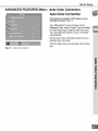
ADVANCED FEATURES Menu: Auto Color Correction
Auto Color Correction
(This feature only applies to 480i signal sources
affecting all inputs.) (Figure 1)
Your Mitsubishi
TV uses six basic colors
(Magenta, Red, Yellow, Green, Cyan and Blue)
for color balancing to optimize skin color tone.
You may refine the colors on your TV screen
automatically.
Set the Auto Color Correction
optimize skin color tone.
option to On to
The Off option does not use Auto color Correction.
Figure 1. Auto Color Correction
iii_i!ii
ii!i i
iiii
iiii_!!!J
iiiiiiii
iiii!
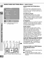
AUDIO/VIDEO
SETTINGS Menu: Audio Output
AUDIO/VIDEO
SETTINGS
Menu
(Figure 1)
Each of the seven or eight inputs has its own
A/V memory. You can adjust each input's A/V
memory in two ways. You can use the menu or
the remote control.
A/V Memory Reset
A/V Memory Reset will return the currently
selected input's A/V memory to the factory
settings. To reset an input's A/V memory, select
A/V Memory Reset, select the input you want to
reset, and press ENTER.
TV Speakers
This selection
Figure 1. AUDIO/VIDEO SETTINGS menu
(A/V Memory Reset)
will turn on or off the TV's internal
speakers. You may select Off when sending
the sound through a separate stereo system or
surround sound A/V receiver.
Audio Output
Select Fixed if your audio receiver or stereo
system can be controlled with a remote. This
allows you to adjust the volume with the
system's remote control or the TV remote
control, if compatible.
This setting is better for
surround sound receivers. Select Variable if
your audio receiver or stereo system cannot be
controlled with a remote. This allows the TV's
internal circuitry to adjust the volume.
AUDIO SETTINGS and VIDEO SETTINGS
!DE :
I PUT
After selecting AUDIO SETTINGS or VIDEO
SETTINGS, you can adjust the settings by
pressing A, v, q, or b. For descriptions of
the individual A/V settings see A/V Setting
Descriptions, pages 49-50.
Using the AUDIO and VIDEO Buttons
on the Remote Control
(Figure 2)
Figure 2. The AUDIO, VIDEO, and ADJUST buttons.
[]
Press AUDIO or VIDEO to cycle through
available settings.
the
[]
Press ql or b to adjust the setting. After 5
seconds of inactivity, the setting display will
disappear.
Part II1: Setup
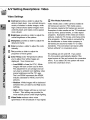
A/V Setting Descriptions:
Audio
Audio Settings
Bass enhances
sound.
or reduces
low frequency
Treble enhances or reduces high frequency
sound.
Balance adjusts the level of sound between
the left and right speakers.
Surround
surround
creates simulated stereo and
effects. Your choices are:
• Off: No surround
effects.
Use this
setting when using an A/V receiver with
Dolby TM Pro Logic Surround, or Dolby TM
Digital Surround.
• Simulated
Stereo: Your TV will create a
simulated stereo effect when watching a
non-stereo program.
• Surround
Sound: Your TV will create a
simulated surround
a stereo program.
effect when watching
Listen to (for Ant-A and Ant-B) determines
how your TV will receive a broadcast audio
signal and play back the sound you hear.
Your choices are:
• Stereo: Default setting. The TV will play
stereo broadcasts in stereo and mono
broadcasts in mono. The word "Stereo"
will be displayed when you tune to a
channel broadcasting stereo.
• SAP (Second Audio Program):
Additional monaural soundtrack that you
cannot hear during normal TV viewing.
The SAP signal might be related to the
program you are watching, such as a
soundtrack in a foreign language, or
unrelated to the program you are
watching such as a weather report. If a
SAP signal is broadcast, the letters "SAP"
will be displayed when you tune to the
channel.
• Mono: Reduces background noise and
should be used when receiving a weak
stereo audio signal. All audio will be
played mono with this setting.
-,,"_Listen
to (for INPUTs) is not available.
Level Sound automatically equalizes
the volume level of programs containing
significant level differences from one
segment to another (for example, regular
programming to commercials).
To receive
the best fidelity with music programs, you
can turn this setting to Off.
Setting Descriptions: Video
Video Settings
m
Contrast
provides a slider to adjust the
white-to-black
level. Low contrast shows a
variety of shades in darker images, while
high contrast shows darker images more
uniformly black and makes colors appear
more vibrant.
Brightness provides a slider to adjust the
overall brightness of the picture.
Sharpness
provides
detail and clarity.
m
Color provides
intensity.
a slider to adjust the
a slider to adjust the color
Tint provides a slider to adjust the
proportion of red to green.
Color Temp (Color Temperature) allows
you to adjust how white images are
displayed. Your choices are:
• Low 6500K or Low (for DTV): White
images will have a warm cast to them.
This adjustment is an average and can
vary due to ambient room lighting, video
scene brightness and the TV's age.
The Low 6500K represents the 6500K
industry standard for NTSC (non-DTV)
pictures.
• Medium: White images will be balanced
between the Low (warm) and High (cool)
settings.
• High: White images will have a cool cast
to them. This setting may provide the
most realistic picture under bright lighting.
Video Noise reduces minor noise
(graininess) in the broadcast or input signal.
Film Mode (Automatic)
Video media uses a video camera created at
30 frames per second. Film media uses a
film camera created at 24 frames per second.
Examples of video media are live TV broadcast
such as news, special events, or video taped
programs. Examples of film media are motion
pictures, made-for-TV movies, and many prime
time programs. Filmed media is converted by
the broadcaster or home video company to
30 frames per second to match TV or video
standards.
This conversion can leave subtle
"picture artifacts"
or conversion
errors.
The settings are On and Off. If you select
On, the system automatically detects if the
signal source is Film and corrects for conversion
errors. If you select Off, the system will never
correct for conversion errors.
Part II1: Setup
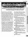
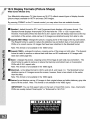
Warning:
Do not leave stationary, PIP/POP, or letterbox images on-screen
for extended periods of time. Mix the types of pictures shown.
Uneven picture tube aging is NOT covered by your warranty.
The normal use of a TV should include a
mixture of TV picture types. The most
frequently used picture types should fill the
screen with constantly moving images rather
than stationary images or patterns. Displaying
the same stationary patterns over extended
periods of time or displaying the same
stationary pattern frequently may leave a subtle
but permanent ghost image. To avoid this, mix
your viewing pattern. Do not show the same
stationary image for more than 15% of your
total TV viewing in any given week. Display
constantly moving and changing
images that fill the screen whenever possible.
This projection TV uses picture tubes to project
the image to the screen. All picture tubes
age with use. As they age, their light output
is gradually reduced. Normal TV pictures fill
the screen with constantly changing images.
Under these conditions, picture tubes age at
an even rate across the entire screen. This
maintains a TV picture that is evenly bright
over the whole screen. Stationary images or
images that only partially fill the screen
(leaving black or colored bars to fill the screen),
when used over extended periods of time or
when viewed repeatedly may cause uneven
aging of the phosphors and leave subtle ghosts
of the stationary images in the picture.
Still or stationary images may be received
from broadcasters, cable channels, satellite
channels, DVD discs, video tapes, laser
discs, on-line services, web/Internet
searching devices, video games, and digital
TV tuner/converter
boxes. Examples of these
types of images can be, but are not limited to
the following:
Letterbox top/bottom
black bars:
shown at the top and bottom of the TV
screen when you watch a widescreen
(16:9) movie on a standard (4:3) TV.
.=='_Side bar images:
solid bars shown
on each side of an image when
watching a standard (4:3) program
...
a widescreen
Stock-market
on
(16:9) TV.
report bars: ticker
running at the bottom of the TV
screen.
.,,='_Shopping
displays:
channel
bright
Iogos & pricing
graphics
shown constantly
same location.
that are
or repeatedly
.,,='_Video game patterns
in the
and scoreboards
Bright station Iogos: moving or
low-contrast graphics are less likely
to cause uneven aging of the picture
tubes.
Online (Internet)
stationary
or repetitive
images.
Closed
websites:
Captioning
or any other
computer
style
Control Functions: Overview
Overview
(Following page, Figure 1)
[]
[]
[]
[]
[]
Slide Switch: Select A/V product to be
controlled by the remote control.
Numbers:
Individually select channels or
input information into TV.
POWER: Turns power on and off for TV and
other A/V products.
SQV (Super Quick ViewTM): Scan through
a memorized list of favorite channels.
[]
QV (Quick ViewTM): Switch to last channel
viewed.
SLEEP: Set the TV to turn off within 2
[]
[]
[]
hours. See Sleep
instructions.
VIDEO: Select the
AUDIO: Select the
MUTE: Turn sound
[]
[]
[]
[]
[]
[]
V-CHIP: Enable/Disable
the V-Chip Lock.
FORMAT: Change the shape and size of the
main TV picture.
PIP INPUT: Select the PIP or POP input
source.
PIP/POP: Cycle through PIP and POP
display choices.
PIP OH: Scroll up or down through
memorized channels in PIP or POP.
REC: Manually record with your VCR.
STOP: Stop your VCR, DVD, or CD.
PAUSE: Pause your VCR, DVD, CD, or
freeze the PIP or POP image.
REW/REV: Rewind or reverse search with
your VCR, reverse scan with your DVD, or
skip reverse with your CD.
PLAY: Play your VCR, DVD, or CD.
FF/FWD: Fast forward or forward search
[]
[]
[]
video settings.
audio settings.
on or off.
[]
[]
[]
INPUT: Select the signal to view
(Ant-A, Ant-B, DTV, Input-l, Input-2, Input-3,
Component-t,
or Component-2).
CHANNEL: Scroll up or down through
memorized channels.
VOLUME: Change sound level.
ENTER/EXCH:
Select a channel number
[]
main TV picture.
HOME: Exit on-screen menus and return
to TV viewing.
ADJUST: Navigate menus, change
[]
settings,
location.
CANCEL:
[]
entries.
MENU: Display l_J]_011]l" on-screen menu
[]
GUIDE: When the slide switch is set
to CABLE/DBS/DTV,
display the on-screen
program guide (some cable boxes and
DBS/DTV receivers).
Timer, page 56, for setup
or menu item. Exchange PIP or POP and
[]
[]
and move the PIP on-screen
Clear SQV and some menu
system.
INFO: Display on-screen summary of
the current input used and any broadcast
information available (including current
V-Chip information, Signal Source and
Format). Additionally, if you press the INFO
key, it will display time, day and sleep time.
[]
[]
[]
with your VCR, fast play with your DVD, or
skip forward with your CD.
Part IV: Operation
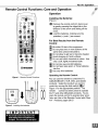
Remote Control Functions: Care and Operation
Operation
Installing
the Batteries:
(Figure 2)
[]
[]
Remove
by gently
direction
cover.
Load the
polarities
the remote control's back cover
pressing the ridged tab in the
of the arrow and sliding off the
batteries,
making sure the
(+) and (-) are correct.
For Best Results from the Remote
Control:
m. Be within 20 feet of the equipment.
... Do not press two or more buttons at the
same time unless instructed to.
F,_E_
T_L_y
... Do not allow to get wet or become heated.
...'q Avoid dropping on hard surfaces.
... Do not use harsh chemicals to clean. Use
only a soft, lightly moistened cloth.
-.- Do not mix new and old batteries.
... Do not heat, take apart, or throw batteries
into fire.
FF_
...
Use only AAA batteries.
Operating
Figure I. Remote Control Functions.
[]
Fq_
L_LJ
Figure 2. Installing the batteries.
size AAA
batteries
the Remote
Control:
You can use the remote to control the TV,
CABLE/DBS/DTV,
VCR, DVD, and AUDIO
products. Select the product you want to
control by moving the slide switch ( [] of
Figure 1) to the appropriate position. The
remote
control has been preset to operate
the TV and other Mitsubishi products. To program the remote control to operate other products, see Use of the Remote Control with Other
A/V Products, pages 26-27.
Control Functions: Channel Selection, Sleep Timer
Channel Selection
For Non-DTV
Channels:
Enter three numbers (for channel 2, press
002).
Or
Press the channel number and ENTER (for
channel 2, press 2, then ENTER).
Or
Enter the channel number and wait four
seconds. The TV will change automatically.
Sleep Timer
Setting the Sleep Timer:
Press SLEEP on the remote control.
A message indicating the length of time
the sleep timer is to be set appears on
the TV screen.
Each press of SLEEP will increase
the time displayed by 30 minutes, until
the maximum value of 120 minutes is
reached.
After 5 seconds of inactivity, the
message will disappear.
Press SLEEP to view the remaining time
before the timer turns the TV off.
Canceling
the Sleep Timer:
Press SLEEP to display the on-screen
message.
Press SLEEP repeatedly until OFF is
displayed. After 5 seconds of inactivity,
the message will disappear.
Part IV: Operation
Control Functions: Special Functions
When your remote control has been Programmed to operate another manufacturer's
)roduct, the function performed on each layer may vary. The most common functions
• POWER
•PLAY
oPOWER
• CHANNEL
u_down
00-9 Number Buttons
• ADJUST u pLdown$1_lff/right
(on some models)
• GUIDE (on some models)
•VOLUME
• Direct In
• POWER
• FF/FWD
"R EW/R EV
•ENTER
(on some model.s)
•CANCEL
(on some models)
(on some models)
• POWER
• PLAY
• PAUSE
•STOP
Buttons
IPLAY
•MUTE
uze number
=FHFWD
are:
SQV and QV )n some models)
-REW/REV
-AIRROWu!ddown/lefl:tright
• MENU
•STOP
• 09 Number Buttons
(onsomemc,:lels)
(on some models)
Remote Control
Functions:
.PAUSE
.STOP
-PAUSE
=CANCEL(onsomemodels
eREW/REV
•ENTER
Operation
of PIP and POP
Picture(POP)
Picture-In-Picturefeaturesallowyoutoview
(PIP) and Picture-Outside-
Figures1-4onfollowingpage/Figure1-5onpage62
Activating
the PIP and POP
Programming in different ways. While watching
the main screen, you can display programs from
other channels and other inputs. To see which
inputs can and cannot be used together, see
How ConnectionsAffect
the PIPandPOPTable 1, page 14. You can display largeand
small PIPs, side-by-side pictures, three POPs,
Press PIP/POP to choose a display format.
Each time the PIP/POP button is pressed on
the TV remote control (within 3 seconds of each
other), the PIP/POP cycles through the following
display options.
[]
POP: side-by-side
or nine POPs.
[]
[]
[]
[]
POP:
PIP:
PIP:
POP:
.................................
pictures
three POPs
large PIP
small PIP
nine POPs (Widescreen
models Only)
To turn PIP/POP Off, wait at least 10 seconds,
and press PIP/POP. The next time you activate
PIP/POP, the last used PIP/POP format will be
displayed first.
Part IV: Operation
Operation of PIP and POP
4:3 Narrow Screen Set:
Model VS-A50
You have the option to view two TV shows or inputs at the same time. For example, you can
watch a game show or a sports event on another channel or a DVD movie. The PIP option
allows you to view another input as a picture-inside-picture. The POP option allows you to view
a main picture and another input as a side-by-side or three pictures-outside-picture at the side
(only one moving POP).
Changing
PIP/POP Inputs
Press PIP INPUT to browse through
[]
available
PIP or POP images.
MAIN
PICTURE
Side-by-Side
Changing
PIP/POP Channels
Press PIP CH to scroll up or down through
memorizes channels on the Ant-A and Ant-B.
Exchanging
Program Images
Press ENTER/EXCH
to exchange the main
picture with the PIP / POP picture.
POP1
[]
MAIN
PICTURE
Moving PIP Images
POP2
Press ADJUST A, v, dl, or I_ to move the PIP
display anywhere on the main screen.
POP3
Automatic
POP Switching
When automatic POP switching is active, the TV
cycles through memorized channels, or strobe
pictures from other A/V components in the
POP display. Press PAUSE to activate/pause
automatic POP switching.
Selecting
..............................................................i
RpA.Oll
_%-I
i
POP "Live"
Image
Press ADJUST A, v, q, or b to select a
different POP "live" image (automatic POP
switching must be paused).
Freeze the PIP and Side-By-Side
Picture
Press PAUSE to freeze the PIP and side-by-side
images. Press Pause again to return to a "live"
image.
4:3 Display Formats (Picture Shape)
Mode
VS-A50
On y
Your Mitsubishi narrow screen TV (also known as 4:3 TV) reflects several types of display formats
depending upon the type of input available for HDTV and many DVD images.
By pressing
FORMAT on the TV remote control, you may select from four available formats:
[]
Standard - default format fills the screen with the entire picture and squeezes
definition) pictures.
HD (high
[]
Expand
This is useful to
- enlarges the picture and crops off some of the image at each side.
correct distorted
HDTV images and fill the screen (Only available
for 1080i images).
[]
Zoom - enlarges the picture, cropping off some of the image at each side. The Zoom
format is useful when you want to remove or reduce the black top and bottom bars
(only available for 480i/480p
images).
[]
Letterbox - (HD 1080i signals only) fills the screen and adds gray bars on top and bottom. The
Letterbox format displays the correct aspect ratio ideal for widescreen viewing, with a vertical
picture area resolution
of 810i.
IMPORTANT:You can find aspect ratios on the back of most DVD covers.
are usually marked "Anamorphic" or "Enhanced for 16:9 TVs."
Also, Anamorphic
_ES
YB
YB
Inp6_=l
_5
NQ
DVDs
Part IV: Operation
For the 4:3 Models
Note the difference
Normal
between the appearance
Broadcast
Standard
(Recommended)
Picture
(4:3)
of figures in Normal Broadcast
Widescreen
and Widescreen
Picture
Picture.
- HD 1080i
(16:9)
Standard
(Not Recommended)
F
1
Zoom
(Recommended for Letterbox)
Expand
(Recommended for Broadcast with Black Side Bars)
Letterbox
(Recommended)
Operation of PIP and POP (16:9 Widescreen
Set)
Picture Inside Picture (PIP) vs. Picture Outside Picture (POP)
You have the option to view two TV shows or inputs at the same time. For example, you can
watch a game show and a sports event on another channel, or a DVD movie and more. The PIP
option allows you to view another input as a picture-inside-picture.
The POP option allows you to
view a main picture and another input as a side-by-side or three or nine pictures-outside-picture
at the side (only one moving POP).
Changing
PIP/POP Inputs
Press PIP INPUT to browse through
]
MAIN
PICTU RE
available
PIP or POP images.
Side-by-Side
Changing
PIP/POP Channels
Press PIP CH to scroll up or down through
memorizes channels on the Ant-A and Ant-B.
Exchanging
Program Images
Press ENTER/EXCH
to exchange the main
picture with the PIP / POP picture.
i!i!iii
ili ii!!ii!iiii:!i!ii
iii:i i:!i!ii!i
iiii:i iiiii!i!i!i
i;ilil; iiiiiii!i!:i
Moving PIP Images
Press ADJUST
A, 'lr, q, or I b to move the PIP
display anywhere
Automatic
on the main screen.
POP Switching
When automatic POP switching is active, the TV
cycles through memorized channels, or strobe
pictures from other A/V components in the
POP display. Press PAUSE to activate/pause
automatic POP switching.
Selecting
POP "Live"
Press ADJUST
Image
A, v, ql, or IP to select a
different POP "live" image (automatic
switching must be paused).
POP
Freeze the PIP and Side-By-Side
Picture
]
MAIN
POPI
POP2
POP3
POP 4
POP 5
POP
POP_
POP8
POP
.................................PICTURE
Press PAUSE to freeze the PIP and side-by-side
images. Press Pause again to return to a "live"
image.
Part IV: Operation
For the 16:9 Models
Widescreen
Picture (16:9 - HD 1080i only)
For Example: A True HD Broadcast
Standard
(Recommended)
Expand (Recommended for 4:3 images with Black Side Bars)
Format (picture
shape) availability
based on Input/Signal
NN
6
YES
NO
YES
6
6
YES
NO
YES
YES
NO
Y1_$
NO
NO
Y_
NO
Y_
YES
YES
NO
YES
Y_ES
YES
NO
YES
_S
YES
_S
_S
YES
NO
YES
NO
YES
Y_5
NO
'YEt;
N'O
YES
NO
YES
NO
YES
NO
YES
NO
16:9 Display Formats (Picture Shape)
Wide Screen
Models
Only
Your Mitsubishi widescreen TV (also known as 16:9 TV) reflects several types of display formats
(picture shape) available for HDTV and many DVD images.
By pressing
[]
FORMAT on the TV remote control, you may select from six available formats:
Standard - default format for DTV and Component Input displays a full-screen format. The
Standard format displays Anamorphic DVDs that have the 1.78:1 or 1.85:1 aspect ratios.
However, Anamorphic DVDs that have the 2.35:1 aspect ratio still display black bars at the top
and bottom of the screen, while narrow (4:3) images are stretched
[]
evenly from side to side.
Expand (480i/480p)enlarges the picture, cropping some of the image at the top and bottom.
The Expand format is useful to reduce the letterbox top and bottom bars of non-Anamorphic
DVDs or to correct narrow 4:3 images that have been stretched in the Standard format.
Note: This format is not available
in the 1080i format.
[]
Expand (1080i) - enlarges the picture, cropping some of the image on both sides. This Expand
format is useful to remove or reduce black side bars on HD broadcasts of 4:3 images with
black bars (See page 63).
[]
Zoom
Zoom
DVDs
Note:
[]
Stretched
- enlarges the picture, cropping some of the image at each side, top and bottom. The
format is useful to remove or reduce the black top and bottom bars on Anamorphic
with 2.35:1 aspect ratio.
This format is not available in the 1080i signal.
- is the default format for ANT-A and Ant-B, and Inputs 1-3. The Stretched
stretches narrow 4:3 images across the screen,
than the sides.
Note: This format is not available
[]
format
however, there is less stretch in the center
in the 1080i signal.
Narrow format displays narrow 4:3 images in their original shape and adds stationary
bars to fill the screen. Note: This format is not available in the 1080i signal.
IMPORTANT:
You can find aspect ratios on the back of most DVD covers.
DVDs are usually marked "Anamorphic" or "Enhanced for 16:9 TVs."
gray side
Also, Anamorphic
Part IV: Operation
For the 16:9 Models
Note the difference between the appearanceof figures in Non-Anamorphic (Le_) and Anamorphic Widescreen(Right) pictures
Normal
Broadcast
For Example:
Standard
Picture
(4:3
- 480i1480p)
NON-ANAMORPHIC
DVDs
(Not Recommended)
Widescreen
Picture
For Example:
Standard
(16:9
- 480i1480p)
ANAMORPHIC
DVDs
(Recommended)
Expand (Recommended for Letterbox)
Expand (Not Recommended)
Zoom (Not Recommended)
Zoom (Recommended for 2.35:1 DVDs)
Stretched
Stretched
(Recommended for Standard Broadcast)
Narrow (Recommended for Occasional Use)
(Not Recommended)
Narrow (Not Recommended)
Appendix
A: Bypassing
the V-Chip Lock
Appendix
A: Bypassing
the V-Chip Lock
Bypassing the V-Chip Lock
O
"1100
m.
m
q,_
After you set the lock, you need your
passcode to view a V-Chip locked program,
view the locked TV, cancel the lock, or enter
the V-Chip lock menus.
If you forget your passcode, you can
view the locked TV without entering your
iiiiiiii:ii!_!iii!i'_ili!i_!ipasscode.
This is done by pressing the
number 9 and QV buttons on the remote
TV control at the same time, when your
password is requested. This process
temporarily unlocks the TV.
O u_
i iiiiil ii!iiii !i
iliiii'i,ii
When entering the V-Chip Lock menu, this
process deletes your old passcode and
!ii_i!i_iiiiii_i
prompts you to enter a new passcode.
"11
mm
;DO
(1}
C
o
m
<
O0
Appendix
Component-1
and Component-2
B: High Definition
Input Connection
Compatibility
Inputs
These inputs are compatible with most
standard DVD and DTV signals with component
video outputs. Compatible DTV signals are
SDTV 480i, 480p, and HDTV 1080i.
All other DTV signals, such as 720p, need to be
converted by the DTV receiver to one of the
compatible signal types. Please check the DTV
receiver specifications before connecting.
Input Levels with Component
=l.0Vp-p
Video
(includes sync) 75ohms
=700mVp-p, 75ohms (can also receive
signals from outputs labeled B- Y and
Cb)
Pr
=700mVp-p, 75ohms (can also receive
signals from outputs labeled R-Y and Cr)
DTV Input
These inputs are compatible with most
standard DVD and DTV signals with component
video outputs. Compatible DTV signals are
SDTV 480i, 480p, and HDTV 1080i.
All other DTV signals, such as 720p, need to be
converted by the DTV receiver to one of the
compatible signal types. Please check the DTV
receiver specifications
before connecting.
Input Levels When Used With
Component Video Signals
EIA - 770.3 Standard
_
_
_
_
_v
This input is also compatible with some DTV
receivers using RGB with "sync on green" or
RGB with "separate H and V sync." Industry
standards for DTV RGB signals systems,
synchronization,
timing, and signal strengths are
not currently established.
These inputs will
not be compatible with all DTV receivers that
offer RGB. If your DTV receiver offers both
DTV component video signals and DTV RGB
signals, Mitsubishi suggests you use the DTV
component video signals. Please check the
DTV receiver specifications before connecting.
Y
Pb
Pr
H
Levels
=l.0Vp-p (includes sync) 75ohms
=700mVp-p, 75ohms
=700mVp-p, 75ohms
= Not Used
= Not Used
Input Levels when Used With RGB
Video Signals
m. G (Y) =1.0Vp-p 75ohms
on green)
B (Pb)=700mVp-p,
(compatible with sync
75ohms
R (Pr)=700mVp-p,
75ohms
H =4Vp-p+/-1.0v, 2.2k ohms
(when using separate H and V sync)
V=4Vp-p+/-1.0v, 2.2k ohms
(when using separate H and V sync)
ii!i_i!_
iiii!¸
iiiiii
Appendix
C: Remote
Control
Programming
A/V Receivers
Mitsubishi ........
..............
Admiral ..........
Aiwa ............
Denon ..........
Fisher ..........
Gerrard ..........
Harman Kardon ....
Jensen ..........
JVC ............
Kenwood ........
Magnavox ........
Marantz
........
Mciintosh ........
Nakamichi ........
Onkyo ..........
Codes
VCRs
010, 011,012, 013, 014,
015
220
225,226
234,235,236
204
213
215
223
232,233
200,208
227,228
224
216
206, 217
209,214,240
Mitsubishi ........
..............
Admiral ..........
Aiwa ............
Akai ............
Audio Dynamic ....
Bell & Howell ......
Broksonic ........
Canon ..........
Citizen ..........
Craig ..........
Curtis Mathes ......
Daewoo ........
DBX ............
Dimensia ........
Emerson ........
..............
Fisher ..........
Funai ..........
GE ............
Go Video ........
Goldstar ........
Gradiente ........
Hitachi ..........
Instant Replay ....
Jensen ..........
JVC ............
Kenwood ........
LXI ............
..............
Magnavox ........
Marantz
........
Marta ..........
Memorex ........
MGA ..........
Minolta ..........
Multitech ........
NEC ............
Olympic
........
Optimus ........
Orion ..........
Panasonic ........
Penney ..........
..............
Pentax ..........
Philco ..........
..............
Philips ..........
Pioneer ..........
Proscan ........
..............
Quasar ..........
Radio Shack ......
..............
RCA ............
..............
Realistic ........
Samsung ........
Sansui ..........
Sanyo ..........
Scott ..........
..............
Sears ..........
Shaintom ........
Sharp ..........
Signature 2000 ....
Singer ..........
Sony ..........
..............
SV2000 ..........
Sylvania ........
Symphonic
......
Tashiro ..........
Tatung ..........
TEAC ..........
Technics ........
Teknika ..........
Toshiba ..........
Totevision ........
Vector Research ....
Wards ..........
Yamaha ..........
Zenith ..........
Cable Box
001,002, 060, 067, 068, 061,
062
055
047, 052
049, 034, 035, 036
059, 031
025, 033
040, 046
043, 045
026
025, 049, 026
065,044, 047
063, 021,044, 079
059, 030, 031
065
023, 036, 039, 040, 045, 046
062,063
025, 028, 029, 027,033
047, 046, 040,054
057, 065,044
057, 069, 070, 071
026
054
043, 065, 020,047
044, 043
059
059, 030, 031,054, 076, 077
059, 030, 026, 031
047, 026, 020, 027, 028, 025,
029
051,043, 044
059, 030, 031
026
044, 029
058,060, 067, 068, 061,062
020, 065
067, 047, 024
059, 030, 031,054
044, 043
048,041,055, 026
046,040
043, 044, 041,042
044, 020, 065, 025, 059, 030
031
020, 031,065
051,044, 047, 043, 046, 040,
063
051,043, 044
043
065,020, 043, 044, 051,066
021,022, 053
041,042, 043, 044
053, 044, 025, 056, 029, 060
047
053, 065, 020, 043,044, 049
051,066, 021,022,079
044, 025,056, 029, 060, 047
057, 022, 024, 053
059, 046, 040, 072
025, 029,033
021,022,024, 029, 058,060
067, 068, 046, 040
025, 026, 027, 028, 020
037
055, 056
047, 055
037
048, 049, 050, 073, 074, 075,
079
047
051,043, 044, 047
047
026
059, 030, 031
059, 030, 047, 031
032, 041,042,043, 044
044, 047
021
026
031
055, 056, 029, 064, 026
025, 059, 030, 031,031
064,026
Opl,mUSpanesonic
........
.......219,216,221203'227'231'230
Philips ..........
Pioneer ..........
223
205,207
RCA ............
203,205,227,231,230
auaser..........
219,216,221
Sansu,
203,211,239
Sharp ..........
..........
234,237
Sound-sighSony
..........
...... 238222
TEAC
..........
212,213,210,211
DVD Players
Mitsub_shi
........
003
Denon ..........
Ferguson ........
250
251
,257
Philips/Magnavox
. . 258
RCA/Proscan ......
Saba
..........
251,255
251
Toshiba ..........
253
ThompsonS°ny
..........
........251254
Yamaha
.......... 250
Zenith
.......... 259
Satellite Receivers
Mitsub,sh-_---Echestar/Dishnetwork
175
!!i'ili!i
ii;il
HD
!iReee,ver
Sate,,,te
005
G_
............
176
i!
H,taeh,
..........173,161
=,i:!iiill
Hu9hes
.......... 173
Panesonic
........ 174
Philips ..........
171,172
RCA............
176,179,180
uniden..........
171,172
Sony
..........
Toshiba ..........
177
170
i!: i i !iiiiiii;ii!ii iiiii:iii i:!!ii:!;iiii
ABC ............
Archer ..........
Cableview ........
Citizen ..........
CoIor Voice ......
Comtronics
......
Curtis ..........
Diamond ........
Eagle ..........
Eastern ..........
GC Brand ........
GE ............
Gemini ..........
General instrument
/Jerrold
........
..............
Hamlin ..........
..............
Hitachi ..........
Macom ..........
Magnavox ........
..............
Memorex ........
Movietime ........
Oak ............
Panasonic ........
Paragon ........
Philips ..........
..............
Pioneer ..........
Pulsar ..........
Puser ..........
RCA ............
Realistic ........
Regal ..........
..............
Regency ........
Rembrant ........
Samsung ........
Satellite ..........
Scientific Atlanta ....
Signature ........
..............
SL Mark ........
Sprucer ..........
Starcom ........
..............
Stargate ........
Teleview ........
Texscan
........
Tocom ..........
Toshiba ..........
Unika ..........
United Artists ......
United Cable ......
..............
Universal ........
Videoway ........
Viewstar ........
Zenith ..........
124
132, 125
105, 132
122, 105
128, 129, 130, 106, 107
128, 129, 130,106, 107
112, 113
124, 132,125
129
134
132, 105
111,112, 113
122, 143
111,119, 120, 121,122,
123 124, 125, 126, 127
140, 141,142, 145, 118,
112
103, 124
103, 104, 105, 108
126, 129, 130, 106, 107,
133, 138
130
132
139, 137, 102
109, 110, 114
117
128, 129, 130, 106, 107,
133, 138
101,116
105, 132
132
115
132
112, 118, 140, 141,142,
145
134
137, 132, 105, 138
105
100
111,112, 113
119, 124, 125, 126, 127,
120, 121, 122,111
105, 101
105, 110
119, 124, 125, 126, 127,
120, 121, 122,111
132, 105
101,105
144
135, 136
104
132, 125
139, 137, 102
119, 124, 125, 126, 127,
120, 121, 122,111
122, 132
106
129, 130
117,100
Appendix D: Cleaning and Service
Cleaning
Normally, light dusting with a dry,
non-scratching
duster will keep your TV clean.
If cleaning beyond this is needed, please use
the following
guidelines:
Cloth speaker
grills:
Lightly brush with a soft brush.
=,- If necessary, you can vacuum using the
brush and hose attachments of your vacuum
cleaner. Do not use the beater brush section
on
the grill cloth.
General
Top and sides of the TV:
=.. Gently wipe down your TV with a soft,
non-abrasive cloth such as cotton flannel or a
clean cloth diaper, lightly moistened
with water.
Dry with a second dry, soft, non-abrasive
cloth.
Cleaning
Warnings:
-.- DO NOT allow liquid to enter the TV through
the ventilation
slots or any crevice.
-.- DO NOT use any strong or abrasive
cleaners as these can scratch the surfaces.
==. For oily dirt, add a few drops of mild liquid
detergent, such as dishwashing detergent to the
water used to moisten the cloth. Rinse with a
-.- DO NOT use any cleaners with ammonia,
bleach, alcohol, benzine, or thinners as these
can dull the surfaces.
second cloth moistened only with water.
with a third dry, soft, non-abrasive cloth.
=,- DO NOT spray liquids or cleaners
the TV's surfaces.
Dry
directly on
-.- DO NOT scrub or rub the TV harshly.
Screen
behind the Diamond
=.. Follow the instructions
it gently.
ShieldTa:
for the top and sides,
however, wipe gently in an up and down motion,
following
the grooves in the screen.
-- Clean the entire screen evenly, not just
sections of the screen.
--
Do not allow liquid to drip down the grooves
of the screen as some liquid may enter the TV
between the screen and the screen frame.
You may purchase Mitsubishi Screen
Cleaner, part number CLEANING-VSS,
calling (800) 553-7278.
by
Wipe
i_
Appendix
E: Diamond
Shield Instructions
Diamond Shield TMInstallation and Removal Procedure
(WS-A48)
Follow the steps below to install and remove the
Diamond Shield TM
INSTALLATION
Note:
Included
package
in the Diamond
are the following
Shield
_.\..- - --._,./
TM
items:
!
I
[]
(1) Diamond
Shield
[]
(2) Molding Clips
TM
[]
i
,L__J,
I
[]
CarefullyremovetheDiamondShieldZMfromits
protectivepackaging.
Wipeoffanydustwithalint-free
cloth.
[] Begin by inserting
the shield, sliding it into the
channels,
starting
at the bottom.
Gently bow the
Install the left and right molding clips by pressing
themintotheopeningstartingatacomer.
force the clip. The clip will slide into place. Donor
This
completesthe
Diamond
Shield
TM
installation.
REMOVAL
ToremovetheDiamondShieldTM,
theaboveprocedure.
I
/,
i!
,
DiamondShieldZMtowardyouandinsertthe
Diamond Shield TM into the top channel.
[]
I
reversetheorderof
>
i
i
Appendix
E: Diamond
Shield Installation
and
Diamond Shield TMInstallation and Removal Procedure
(VS-A50, WS-A55 and WS-A65)
Follow the steps below to install and remove the
Diamond Shield TM
INSTALLATION
Note: Included in the Diamond Shield TM
package are the following items:
[]
(1) Diamond
[]
(2) Molding Clips
[]
Carefully
protective
cloth.
[]
Shield TM
remove the Diamond
packaging.
Begin by inserting
Shield TMfrom its
Wipe off any dust with a lint-free
the shield, sliding it into the
channels, starting at one side. Gently bow the
Diamond Shield TMtoward you and insert the other side
of the Diamond
[]
Shield TMinto the oppositive
channel.
Install the top and bottom molding clips by pressing
them into the opening
starting at a corner.
Do not
force the clip. The clip will slide into place. This
completes the Diamond Shield TM installation.
REMOVAL
To remove the Diamond
Shield TM,
reverse the order of the above procedure.
Removal
Appendix
F: Cabinet
Cabinet Separation for Model WS-A65
Inst_s
for _rat_g
For MP,subishi
This M_blShl
T_
p_cti0n
_Th_
w-,e_
_
IO
Oeak_rs _d
_
_
below _w
proj_
_n
_m
_,L_RE_
_ d_cot'adwP_
_rs
_no]
h_
how to _e_j
overt_
be_
_E
_d
_
ONLY
_mb_
to aJ_ for e_iet del_
_
_
_
_
_in_
p_S_S may _ _r_
The |nstructi_
_
_
_tate
_
in _o
end setup.
and re_*_ac_ the _l_t.
and has ____
bytJ_
THE_.
_.
\
i_ o_ ea_hside
0
Separation
Problem
The TV remote control does not work.
Possible Solution
• Check that the batteries are installedcorrectly.
• Check that the selected switch is set to "TV._
• Be no further than 20 feet from the TV when using the
remote control.
The TV takes several seconds to respond to
channel commands.
• Press ENTER after a channel number to avoid delays.
• Use the three digit number, i.e 002 for channel 2.
You cannot access a channel.
• Use number keys instead of CHANNEL up/down.
• Be sure the channel you want to view is in memory.
• Check that the TV is turned to the correct inputsource for
that channel, by pressing the INPUT button.
• Make sure the V-Chip setting is off (page 40).
On-screen displays appear each time you change a function. • This is part of normal TV operation.
You cannot programthe TV to turn on automatically.
• The TV may be locked.
• The clock may not be set.
There is no sound even when the volume is turned up.
• Check to see ifthe MUTE button is on.
• The TV's "Listen to:" setting may be set to SAP.
• Check that "TV Speakers_setting is ON.
You have forgotten your lock passcode.
• See AppendixA, Bypassing the V-Chip Lock, page 66.
PIP does not display a picture.
• Make sure the V-Chip setting is off (page 40).
• Not all inputs can be displayed as a PIP (page 14).
The sound does not match the screen picture.
• The TV's "Listen to:" setting may be set to SAP.
• If using stereo or A/V reveiver speakers, check input
selection on the stereo or A/V receiver.
• If using stereo or A/V receiver, check that AUDIO isfrom
MONITOR OUT on TV's back panel.
There isa large black or gray rectangle on the screen.
• The TV closed captioning has been set to "text" mode, but
there is no text informationbeing broadcast. Turn Off in the
CAPTIONS menu (page 35).
You cannot see a picturewhen you play a VCR tape.
• If you connected your VCR with A/V cables, use the INPUT
button to select the Input source (INPUT-I, INPUT-2, or
INPUT-3 ) that the VCR is connected to.
• Check your VCRs owner's guide for further troubleshooting.
V-Chip Lock is not working
• Make sure that V-Chip is On (page 40).
• If V-Chip Hours/Lock by Time is currently set to disable the
V-Chip lock, the V-Chip will not block programming.
Appendix
Problem
• Cannot set adjustments to factory settings
G: Troubleshooting
Possible Solution
•Follow the steps below to reset system defaults to factory
settings.
1. Press the MENU button followed by number buttons 1, 2,
and 3 on the remote control.
Result: The above steps activate the Reset System
Defaults menu screen.
2. Press the ENTER button on the remote control.
Result: The settings reset to factory defaults.
3. Press the HOME or MENU button on the remote control to
return to the HOME or MENU screen.
IMPORTANT: This function is not recommended unless it is
mandatory to reset system defaults to factory settings. This
operation CANNOT be undone and all custom settings will be
erased.
E
adding and deleting
Advanced
43-47
channels,
Features
menu, 30,
adaptors
(BNC to RCA), 20
adjusting
(convergence),
alignment
(convergence),
antennas
(connecting),
audio settings,
38
45-46
45-46
13, 16-17
48, 49
Auto Color Correction,
N
espa5ol,
32
54-55
F
Film Mode (Automatic),
formats
naming
38
inputs, 31
P
(display),
front control
47
naming channels,
EXCH button on remote,
50
60-65
passcode,
42
Picture-in-Picture
58-59, 62
panel, 12
(PIP), 9, 14,
Picture-outside-Picture(POP),
14,58-59,62
9,
G
B
games, 23, 51
ghost, 23, 51
R
back panel, 13
balance,
remote control
49
Settings
bass, 49
Black Enhancement,
blocking
(enabling
brightness,
46
V-Chip),
40-42
50
bypassing
1-
Audio, 49
--_
Video, 50
IMPORTANT
Important
(V-Chip-Lock),
66
NOTES,
Safeguards,
Input Terminal
23, 51
care and operation,
4-5
channel
Cover, 72
4, 69
L
Clock (setting), 33-34
compatibility
(signal), 67
language, 32
letterbox, 23, 51, 60
contrast,
Lock by Time, 42
50
convergence,
45-46
programming
codes,
replacement,
6
reset convergence,
Sleep Timer, 56
reset (A/V), 48
locked, 40-42
21ar
34
daylight
savings
dusting,
69
time (DST),
maintenance,
33
memorize
memory
55
26-27, 68
46
O
Quick View
date (setting),
56
functions, 54-65
installing batteries,
C
cleaning,
selection,
55
2, 74
channels,
(channel),
31
38
TM
(QV), 54
Index
S
IF
safeguards,
servicing,
V-Chip
4-5
bypassing,
2, 5
1080i, 14, 60-61, 63-65,
480i, 14, 60-61,
67
Lock by Time, 42
63-65, 67
480p (progressive
60-61, 63-65, 67
passcode
DVD), 14,
sound (adjusting),
42
ratings and categories,
41
41
V-Chip, 40,41
48-49
V-Chip Hours, 42
32
ventilation,
Functions
screen,
signal information,
Sleep Timer, 56
Special
66
entry to, 40
signal types
Spanish,
Lock, 40-42
(Remote),
58
SQV (Super Quick ViewTM), 28,54
4, 69
Video Mute, 46
Video Settings,
50
stand, 4
STATIONARY
WARNING,
surface,
surges,
PICTURE
W
23-51
4
Mitsubishi
4
3r"
time (setting),
34
Timer
(turn TV on), 43-44
Timer
(Sleep),
56
treble, 49
Troubleshooting,
TV speakers,
74-75
48
tJ
unpacking,
upgradeable,
9
9
Limited Warranty,
78
MITSUBISHIPROJECTIONTELEVISIONLIMITEDWARRANTY
MITSUBtSHIDIGITALELECTRONICSAMERICA,INC. ("MDEA")warrantsto the originalpurchaserof this televisionthat if purchasedfrom an authorized
MITSUBISH{Audio/Video Dealer,shouldit provedefective by reasonof improperworkmanshipand/or material:
a. Parts. The lenticutar i.e. front picture screen and/or the DiamondShieldTM iswarranted againstdefectsin materialsand workmanshipfor a period of 30 days.
All other partsare warranted for a periodof one year from the dateof theoriginal purchaseat retail. Wewill repairor replace,at our option, any defective part
withoutcharge for the part. Parts used for replacementmay be replacedwiththose of like kindand quality and may be new or remanufactured. Partsused for
replacementare warrantedfor the remainderof the original warrantyperiod.
b. Labo_ For30 days after the original purchaseat retail, we wilt repairor replace,at our option, the lenticularscreen if it provesdefective. For altother parts,
we will providethe labor for a warranty repairby an authorizedMITSUBISHIservice centerwithout chargefor one year from the original dateor purchaseat
retail.
c. Notice. TOobtain warranty service,you must notify an authorizedMITSUBISHIservice centerof any defectwithinthe applicablewarrantytime period.
1. TO OBTAINWARRANTYSERVICE:
a. Contact yournearestauthorizedMITSUBISHIservice centerwhose nameand address can be obtained from your MITSUBISHIdealeror by writingor caiting
MDEAat the addressand telephone numberprovidedbelow.
b. Warrantyservice will be provided inyour home or, if required,at an authorizedservice shop, providedthat yourtelevisionislocatedwithin thegeographic
territorycustomarilycoveredby an authorizedMITSUBISHIservice center. If not,you must either deliveryour television toan authorizedservice location at
yourown expense,or pay for any travel and/or transportationcosts the service center maycharge to and from your home. Actualservice labor willbe provided
withoutcharge.
c. Proof of purchasedate from an authorizedMITSUBISHIdealeris requiredwhen requestingwarrantyservice. Presentyour sales receiptor other document
whichestablishes proof and dateof purchase. THE RETURN OF THEOWNER REGISTRATIONCARD IS NOTA CONDITIONOF WARRANTYCOVERAGE.
However,pleasereturn the Owner RegistrationCard sothat we can contactyou shoulda questionof safetyarise whichcould affect you.
2. THIS WARRANTYDOESNOTCOVERdamage to DiamondShield,Lenticularscreen or Fresnellens, screen frame,cosmeticdamage orto any otherproduct
wheresuch damage is caused by unauthorizedmodification,alteration, repairsto or service of the productby anyoneother than an authorizedMITSUBISHI
service center; physical abuseto or misuse of the product(includingany failure to carry out any maintenanceas describedin the Owner'sGuideor any product
damaged byexcessivephysical or electricalstress ; any productsthat have had a serial numberor any part thereof altered,defaced or removed;productuse in
any mannercontrary to the Owner's Guide includingunevenpicture tubeaging and imprintedimageson the viewingscreen ; freightdamage; or any damage
caused byacts of God or otherfactors beyond the reasonablecontrolof MDEA, such as powersurge damagecaused byelectrical systemor lightning. This
warrantyalso excludesservice calls where no defect in the productcovered under this warrantyis found,service calls relatedto unsatisfactoryaudio or visual
receptionor signal unless causeda defect inthe productthat is covered underthis warranty,all costs, expensesor any otherdamagesarising from product
installation,
or set-ups,any ed ustmentsof usercontrols includingconvergence,contrast,brightness, color, tint, fine tuning,sharpness, other ed ustment
necessaryto preparethe unit for display or use, connection withany externalaudio receiver,antenna, cable orsateI_itesystems,or service of products
purchasedor serviced outsidethe U.S.A. Pleaseconsult the operating instructions
containedin the Owner'sGuidefurnished withthe productfor information
regardingusercontrols.
3. ANY EXPRESSWARRANTYNOT PROVIDEDHEREIN,ANDANY REMEDYWHICH, BUT FORTHIS PROVISION,MIGHTARISE BYiMPLICATION
OROPERATIONOF LAW,iS HEREBYEXCLUDEDAND DISCLAIMED.THE iMPLiEDWARRANTIESOF MERCHANTABILITYAND FITNESSFOR ANY
PARTICULARPURPOSEARE EXPRESSLYLIMITEDTO A TERM OFONE YEAR.
4. UNDER NOCIRCUMSTANCESSHALL MDEA BE LIABLETO PURCHASEROR ANYOTHERPERSONFORANY INCIDENTAL,SPECIALOR
CONSEQUENTIALDAMAGES,WHETHERARISINGOUT OF BREACHOF WARRANTY,BREACHOF CONTRACT,OROTHERWISE.
5. Some states do not allow limitationsonhow longan impliedwarrartylasts,orthe exclusion or limitationofincidental,special or consequential damages,so
theabove limitationsor exclusions may notapply to you.
6. This warrantygivesyou specific legaIrights, andyou may also have other rights which vary from state to state.
7. BEFOREREQUESTINGSERVICE,ptease reviewthe instruction
bookletto insureproper installation
and correctcustomercontrol adjustment, if the problem
persists,contact yournearest MITSUBISHIDealerfor the name(s)of authorizedMITSUBISHIServiceCenter s. if you are unable to obtain this information,
pleasecal1800-332-2119,Orwrite usat the addressbelow.
MITSUBISHIDIGITALELECTRONICSAMERICA,INC.
9351Jeronirno
Road
Irvine,CA 92618-1904
I RETAIN THIS PORTION
FORYOUR
RECORDS
MITSUBISHI
]
SERIAL
MODEL
DEALER
NAME
STREET
ADDRESS
PHONE NUMBER
NUMBER
NUMBER
ZIP
PURCHASE
DATE