1
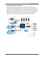
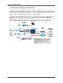
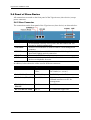
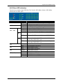
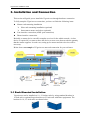
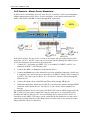
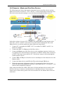
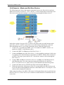
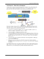
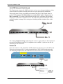
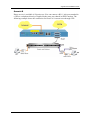
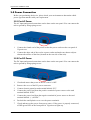
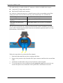
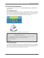
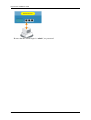
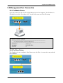
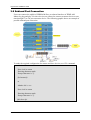
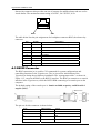
VigorAccess IP DSLAM
Installation Guide
Version: 1.0
Date: 2006/2/14
i
VigorAccess Installation Guide
Copyright Information
Copyright
Declarations
Copyright 2006 All rights reserved. This publication contains information that is
protected by copyright. No part may be reproduced, transmitted, transcribed,
stored in a retrieval system, or translated into any language without written
permission from the copyright holders.
Trademarks
The following trademarks are used in this document:
z
Microsoft is a registered trademark of Microsoft Corp.
z
Windows, Windows 95, 98, Me, NT, 2000, XP and Explorer are
trademarks of Microsoft Corp.
z
Apple and Mac OS are registered trademarks of Apple Computer Inc.
z
Other products may be trademarks or registered trademarks of their
respective manufacturers.
Safety Instructions and Approval
Safety
Instructions
z
z
z
z
z
z
z
z
z
z
z
z
z
Make sure that the AC power source is in the range of AC 90-260V. The
VigorAccess should be used in a sheltered area, within a temperature range
from -10 to +65 °C and relative humidity in the range of 10% and 95%.
DC power source operating condition: -42 to –56VDC. Do not expose the
VigorAccess to direct sunlight or other heat sources. The housing and
electronic components may be damaged by direct sunlight or heat sources.
Read the quick start guide and installation manual before turning on the
power switch of device.
Locate the emergency power-off switch near the device prior to power
connection.
Fixing the device on chassis to maintain air circulation and stable
condition is recommended.
Do not work alone if the operation environment is dangerous.
Check and avoid the potential hazard for moist environment, and
grounding issue for power cable.
Please turn off the power switch when replacing fuse, installing or
removing chassis.
Do not place the device in a damp or humid place, e.g. a bathroom- (such
as this environment).
Avoid operating cable connection during lightning period.
When you want to dispose of the VigorAccess, please follow local
regulations on conservation of the environment.
Users can replace fuses by removing the module and replace it when
necessary. Other components should be repaired by authorized and
qualified personnel. Do not try to open or repair the device by yourself.
The fuse for AC power inlet should be identical to the following standard:
250VAC, 2A
Be a Registered
Owner
Web registration is preferred. You can register your VigorAccess via
http://www.draytek.com. Alternatively, fill in the registration card and mail it to
the address found on the reverse side of the card.
Firmware & Tools
Updates
Due to the continuous evolution of DrayTek technology, all IP DSLAMs will be
regularly upgraded. Please consult the DrayTek web site for more information on
newest firmware, tools and documents.
http://www.draytek.com
i
VigorAccess Installation Guide
European Community Declarations
Manufacturer:
Address:
Product:
DrayTek Corp.
No. 26, Fu Shing Road, HuKou County, HsinChu Industrial Park, Hsin-Chu, Taiwan 303
VigorAccess IP DSLAM
DrayTek Corp. declares that VigorAccess is in compliance with the following essential requirements and
other relevant provisions of R&TTE Directive 1999/5/EEC.
The product conforms to the requirements of Electro-Magnetic Compatibility (EMC) Directive
89/336/EEC by complying with the requirements set forth in EN55022/Class A and EN55024/Class B.
The product conforms to the requirements of Low Voltage (LVD) Directive 73/23/EEC by complying with
the requirements set forth in EN60950.
Regulatory Information
Federal Communication Commission Interference Statement
This equipment has been tested and found to comply with the limits for a Class B digital device, pursuant
to Part 15 of the FCC Rules. These limits are designed to provide reasonable protection against harmful
interference in a residential installation. This equipment generates, uses and can radiate radio frequency
energy and, if not installed and used in accordance with the instructions, may cause harmful interference to
radio communications. However, there is no guarantee that interference will not occur in a particular
installation. If this equipment does cause harmful interference to radio or television reception, which can
be determined by turning the equipment off and on, the use is encouraged to try to correct the interference
by one of the following measures:
z
Reorient or relocate the receiving antenna.
z
Increase the separation between the equipment and receiver.
z
Connect the equipment into an outlet on a circuit different form that to which the receiver is
connected.
z
Consult the dealer or an experienced radio/TV technician for help.
This device complies with Part 15 of the FCC Rules. Operation is subject to the following two conditions:
(1) This device many not cause harmful interference, and
(2) This device may accept any interference received, including interference that may cause undesired
operation.
Taiwanese BSMI (Bureau of Standards, Metrology and Inspection) A Warning:
Warning: This device might cause interference of radio frequency under the environment of dwelling. In
such condition, the users might be asked to adopt some proper strategies.
Please visit www.draytek.com/contact_us/WEEE.php.
ii
VigorAccess Installation Guide
Warranty
We warrant to the original end user (purchaser) that this device will be free from any defects in
workmanship or materials for a period of three (3) years from the date of purchase from the dealer. Please
keep your purchase receipt in a safe place as it serves as proof of date of purchase. During the warranty
period, and upon proof of purchase, should the product have indications of failure due to faulty
workmanship and/or materials, we will, at our discretion, repair or replace the defective products or
components, without charge for either parts or labor, to whatever extent we deem necessary tore-store the
product to proper operating condition. Any replacement will consist of a new or re-manufactured
functionally equivalent product of equal value, and will be offered solely at our discretion. This warranty
will not apply if the product is modified, misused, tampered with, damaged by an act of God, or subjected
to abnormal working conditions. The warranty does not cover the bundled or licensed software of other
vendors. Defects which do not significantly affect the usability of the product will not be covered by the
warranty. We reserve the right to revise the manual and online documentation and to make changes from
time to time in the contents hereof without obligation to notify any person of such revision or changes.
Customer Support
Please prepare the following information before you contact your customer support.
z
Product model and serial number
z
Warranty information
z
Date that you received VigorAccess
z
Product configuration
z
Software release version number
z
Brief description of your problem
The information of customer supports and sales representatives is in www.DrayTek.com, respectively.
iii
VigorAccess Installation Guide
Table of Contents
1. Introduction........................................................................................................... 1
1.1 Features of Vigor Access ........................................................................................................... 1
1.1.1 General Features .......................................................................................................... 1
1.1.2 Quality of Service (QoS) ............................................................................................... 3
1.1.3 Security ......................................................................................................................... 4
1.1.4 Packet Filtering ............................................................................................................. 5
1.1.5 ATM Features ............................................................................................................... 5
1.2 Applications ................................................................................................................................ 6
1.2.1 General Application Scenario ....................................................................................... 7
1.2.2 Commercial Application Scenario ................................................................................. 8
2. Panel Explanation................................................................................................. 9
2.1 System Architecture Overview ................................................................................................... 9
2.2 Master and Slave Devices ......................................................................................................... 9
2.3 Panel of Master Device .............................................................................................................11
2.3.1 Master Connector........................................................................................................ 11
2.3.2 Master LED Indication................................................................................................. 12
2.4 Panel of Slave Device .............................................................................................................. 14
2.4.1 Slave Connector.......................................................................................................... 14
2.4.2 Slave LED Indication................................................................................................... 15
3. Installation and Connection............................................................................... 16
3.1 Rack-Mounted Installation........................................................................................................ 16
3.2 Desktop Placement .................................................................................................................. 17
3.3 Frame Ground Installation........................................................................................................ 18
3.4 ADSL Port Connection ............................................................................................................. 19
3.4.1 MDF (Main Distribution Frame)................................................................................... 19
3.4.2 Scenario – Master Device Standalone........................................................................ 20
2.4.3 Scenario – Master and One Slave Devices ................................................................ 21
2.4.4 Scenario – Master and Six Slave Devices .................................................................. 22
2.4.5 Scenario – Slave Device Standalone.......................................................................... 23
3.4.6 CPP (Centric Patch Panel) ......................................................................................... 24
3.5 Power Connection .................................................................................................................... 26
3.5.1 For AC Power.............................................................................................................. 26
3.5.2 For DC Power ............................................................................................................. 26
3.6 Optical Fiber Connection.......................................................................................................... 27
3.7 Console Port Connection ......................................................................................................... 29
3.7.1 For Master Device....................................................................................................... 29
3.7.2 For Slave Device......................................................................................................... 29
3.8 Management Port Connection ................................................................................................. 31
3.8.1 For Master Device....................................................................................................... 31
3.8.2 For Slave Device......................................................................................................... 31
3.9 Subtend Port Connection ......................................................................................................... 32
iv
VigorAccess Installation Guide
Appendix: Connectors ........................................................................................... 33
A.1 RJ21 DSL Connector ............................................................................................................... 33
A.2 Alarm Relay RJ45 Connector .................................................................................................. 33
A.3 RS232 Connector .................................................................................................................... 34
A.4 Standard 10/100 Base-T Ethernet Interface Connector .......................................................... 35
A.5 Standard 10/100/1000 Base-T Ethernet Interface Connector ................................................. 35
A.6 Contacting Your Dealer ............................................................................................................ 37
v
VigorAccess Installation Guide
1. Introduction
With the explosive growth of Internet, people are becoming more and more relying on
Internet in daily life. The rapidly increase in bandwidth demanded by digital society has
put pressure on the network therefore, bandwidth and performance management are
becoming critical issue for ISP.
VigorAccess, which is equipped with 24 ADSL2/+ ports, is designed for ISP (Internet
Service Provider) to implement bandwidth management for multiple subscribers. As
VigorAccess supports high upstream and downstream bit-rates performance, therefore,
VigorAccess is being deployed primarily for residential customer for IPTV application or
high speed Internet service or business customers to replace expensive T1/E1 leased line.
VigorAccess is not only equipped with a console port being used for local management,
but also provided excellent capabilities of SNMP, Telnet for remote management. In
particular, VigorAccess can be easily configured by EMS. The EMS system covers
topology, configuration, deployment, security, alarm management and backed storage.
Moreover, with the solution of port-based and tag-based VLAN, VigorAccess can isolate
traffic between different users and provide improved security.
1.1 Features of VigorAccess
The VigorAccess (Integrated Ethernet Switch) is an IP-based DSLAM (Internet Digital
Subscriber Line Access Multiplexer) that connects to 24 ADSL subscribers to the Internet.
When deployed together with DSL modems and WAN routers, the combination forms are
integrated solution for providing broadband services to multiple tenants such as
apartments, hotels, offices and campus buildings. VigorAccess supports a lot of features
as listed below.
1.1.1 General Features
z
ADSL Access Module
The name marked “Line” on the front panel is a RJ-21 connector integrated 24
ADSL ports internally. It aggregates traffic from 24 lines to Ethernet port(s) and has
integrated splitters to allow voice and ADSL to be carried over the same phone line
wiring.
z
10/100/1000 Mbps Auto-negotiating Ethernet Port
VigorAccess supports FE/GE auto-negotiate Ethernet ports connecting to an
Ethernet network. It can be aggregated together as a logical port as the backbone,
and provide ADSL service to lots of subscribers.
z
ADSL Compliance
¾
Multi-Mode ADSL standard
¾
G.dmt (ITU-T G.992.1)
¾
G.dmt.bis (ADSL2, G.992.3)
¾
G.dmt.bisplus (ADSL2plus, G.992.5)
¾
G.lite (ITU-T G.992.2)
1
VigorAccess Installation Guide
z
2
¾
G.hs (ITU-T G.994.1)
¾
ANSI T1.413 issue 2
Ethernet Bridging
¾
IEEE 802.1d STD transparent bridging
¾
Up to 4000 MAC entries address table
¾
Port-based VLAN
z
IEEE 802.1Q Tagged VLAN
VigorAccess uses the IEEE 802.1Q Tagged VLAN; users can allow this device to
deliver tagged/untagged frames in these ports. VigorAccess supports up to 512
VLAN groups and can be applied up to 4094 VLAN identifications.
z
IEEE 802.1p Priority
VigorAccess supports IEEE 802.1p to assign priority levels to all individual ports.
Users can set different quality of service for individual application.
For example, voice and video services can set high priority and Internet data service
will be lower priority.
¾ Support 4 queues for per ATM port.
¾ Support 8 queues for per physical Ethernet port.
z
MAC Address (Media Access Control) Filter
¾
VigorAccess can let users use the MAC filter for incoming frames based on
MAC (Media Access Control) addresses that specified by users. Users can
enable/disable this function on specific port.
Access Control List per port is up to 8 entries. If port receives a packet which
source MAC address is met with one of the 8 entries, this packet can be
forwarded to destination port.
¾
Access Control List per device is up to 1024 entries. If port receives a packet
which source MAC address is met with one of these entries, this packet would
not be forwarded to destination port.
The high priority of ACL rules is the allowing rule checking for per port.
z
MAC Address (Media Access Control) Count Filter
VigorAccess supports users to limit the number of MAC addresses that may be
dynamically learned or statically configured on a port. Users can enable/disable this
function on individual ports.
The global static learning table has up to 512 entries. Each entry can be set to a
specific port. In dynamic learning mode, there are 16 MAC address entries in DSL
port and 256 entries in Ethernet uplink port.
z
Multi-Protocol Encapsulation
VigorAccess supports multi-protocol encapsulation over ATM adaptation Layer 5
based on RFC2684.
z
Management
VigorAccess supports some management method as listed below.
¾ Remote configuration backup/restore via EMS client/server.
¾ Remote firmware upgrade
¾ SNMP management
¾ Command Line Interface, it can be accessed by local Console or Telnet
VigorAccess Installation Guide
interface.
z
Multiple PVC on single port
VigorAccess allows you to use different virtual connection also called PVC
(Permanent Virtual Circuits) for different services or subscribers. Users can define
up to 8 connections on each DSL port for different services or levels of service, and
users can assign different priority for each connection.
z
IGMP Snooping
IGMP (Internet Group Management Protocol) snooping reduces multicast traffic for
maximum performance. The feature is very popular for video multicast application
for example IPTV service.
z
Load-sharing Redundancy
These two Ethernet uplinks of VigorAccess can be used as a single load-shared
uplink for data and management path, with a provision to fall back to single one, in
the event one of the links failed.
z
Active Standby Redundancy
These two Ethernet uplinks of VigorAccess can be used in an active stand by mode
for data and management path, with a provision to fall back to standby link, in the
event of the active links failure.
z
Configuration
Modification of Ethernet IP address, mask, speed, and duplex mode is supported.
Support for safe mode boot where the TE Image can be downloaded for field
upgrade.
1.1.2 Quality of Service (QoS)
Quality of Service (QoS) refers to the capability of a network to provide better service to
select network traffic over various technologies. The primary goal of QoS is to provide
priority including dedicated bandwidth, controlled jitter and latency (required by some
real-time and interactive traffic), and improved loss characteristics. Also it is important to
make sure that providing priority for one or more flows does not make other flows fail.
QoS technologies provide the elemental building blocks that will be used for future
business applications in campus, WAN and service provider networks.
z
Prioritized Bridging
VigorAccess supports for multiple queues per port. There are different queues both
on ATM and Ethernet uplink.
¾ Four queues supported per ATM port.
¾ Eight queues supported per physical Ethernet port.
z
Scheduling Mechanism
VigorAccess supports multiple scheduling mechanisms.
¾ Strict Priority Scheduling
¾ Probabilistic Priority Scheduling
z
Rate Limiting
VigorAccess supports rate-limiting function in input/output both direction.
¾ Input Rate Limiting (IRL) on a per-AAL5 interface.
¾ Output Rate Limiting (ORL) on a per ATM-port basis
¾ Output Rate Limiting (ORL) on a per-physical Ethernet Interface basis.
One feature supports for buffer admission control triggered using IRL.
3
VigorAccess Installation Guide
Moreover, it also supports for dynamic modification of ORL on ATM and
Ethernet interfaces.
z
Mapping Table
VigorAccess supports a packet priority to traffic class mapping table supported on a
per egress bridge port.
z
Multiple Mechanisms
VigorAccess supports two multiple mechanisms as below.
Multiple mechanisms of prioritizing incoming traffic are based on a per-bridge port.
¾ Using Source Port configuration (for untagged packets)
¾ Using Packet Classifier actions
¾ Using priority regeneration table (mapping ingress priority to egress priority)
¾ Combination of the above
Multiple mechanisms of 802.1p re-tagging of outgoing traffic is based on a per
ingress bridge port.
¾
¾
¾
¾
z
Using Source Port configuration (for untagged packets)
Using Classifier actions
Using priority regeneration table (mapping ingress priority to egress priority)
Combinations of the above
Abilities
VigorAccess can be able to create multiple scheduling profiles, either Strict Priority
or Probabilistic Priority. It also can be able to share the same profile across multiple
(similar) ports.
1.1.3 Security
VigorAccess supports some different methods to implement this feature in following
sections.
4
z
Rate Limitation
VigorAccess supports a function for throttling flooded packets. Users can configure
some limited rates by per-port.
z
Static Mac Address
VigorAccess supports this feature to be configured with certain ports to learn MAC
addresses on a semi-permanent basis. These learned entries would be treated similar
to the static entries, but will not be subject to aging or overwriting. These only may
be deleted explicitly by management or by making the ports, as non-static after
aging will happen normally.
z
FDB Conflicting Traps
VigorAccess will transmit a trap packet to central manager when any MAC address
moves from one port to another port.
z
MAC Address Tracking
VigorAccess can be configured to track a global list of MAC addresses. When these
MAC addresses move from one port to another port, a trap is generated. Whether
packets from a particular bridge port should be subjected to this tracking is
configurable. This may be used to prevent denial of service from certain MAC
addresses.
VigorAccess Installation Guide
z
Access Control List by MAC address
It can be configured by per-port. It also supports a MAC address deny list, the
application of the MAC address deny list can be enabled/disabled on a per bridge
port basis.
z
Access Control List by IP Address
This feature still can be configured by per-port, and enabled/disabled on a per
bridge port basis.
1.1.4 Packet Filtering
This function is provided for users to setup some rules to filter the specific packets while
receiving packets from logical ports.
VigorAccess supports for rule-based packet filtering, it can be used to implement filtering
required of NetBeui, NetBIOS, DHCP, 802.1x and other protocols.
z
z
Filtering Modes
¾
VigorAccess supports for independent rule ordering and rule ID. It means that
rule ID no longer determines the order in which the rule is applied. The rule can
be modified easily; users can replace a rule sequence of a stage on an interface
by another sequence in one step.
¾
Moreover, VigorAccess also supports for capturing unicast and multicast
packets that fail lookup in the forwarding database is provided. Users may write
their own applications to terminate and act on this information. On the other
side, it also supports for capturing packets coming to Control Plane that do not
match any registered filter.
Multiple Filter Stages
VigorAccess supports a concept of multiple filter stages are provided for ingress and
egress filter rules. Moreover, VigorAccess supports an Egress filtering for unicast,
broadcast and multicast traffic. It also supports multiple actions configurations by
per filter rule.
1.1.5 ATM Features
VigorAccess supports some functions about ATM issue.
z
Remote CPE Management
VigorAccess supports RAW AAL5 interface for remote CPE management.
z
Diagnostic Testing
VigorAccess supports OAM-I.610 end-to-end and segment loop back and DELT.
z
Dynamic Modification
VigorAccess supports a lot of dynamic modifications and is shown as below.
¾
VPI/VCI value (VC should be disabled)
¾
Transmit and receive PDU sizes
¾
Management mode modification per port
¾
Max VPI/VCI bits (interface must be disabled)
¾
Maximum number of VCCs supported
5
VigorAccess Installation Guide
¾
OAM source ID
1.2 Applications
The compact design of VigorAccess is composed of two units. One is Slave for 24-port
ADSL 2/+ with built-in POTS splitters connected to ADSL modems. The other is Master,
which has DSL, optical interfaces, and 6 subtend interfaces. VigorAccess provides lots of
applications such as:
High speed Internet Service - VigorAccess aggregates DSL subscribers and terminates
the encapsulated type ATM cell. Users can easily access Internet through the IP backbone
network.
Gaming application Service - By combining gaming server, VigorAccess can provide
gaming service.
Stream TV Service - VigorAccess uses ADSL 2/+ high speed DSL technology, and
supports stream TV Service.
Video on Demand Service - Service provider can offer multimedia services by setting up
video or content server on the local side. By combining rich content video server,
VigorAccess also provides the video on demanded service. Users can easily access
multimedia content based on VigorAccess architecture.
Combined with VoIP Service - VigorAccess can combine IAD, DSL/VoIP gateway
with highest priority to provide toll quality voice communication in terms of voice quality
and reliability for the users.
Mail or Portal Service - VigorAccess provides the feasibility to connect mail or proxy
server.
The following section provides general and commercial applications scenarios for your
reference.
6
VigorAccess Installation Guide
1.2.1 General Application Scenario
Take the following figure as an example. For users living in the same building,
VigorAccess can set up additional Video Server, Mail Server, Proxy Server and Game
Server in the network different from the ones set up by ISP, and allows users to share the
multiple services. In addition, the users can access into Intranet through WAN ports, to
communicate with others with PSTN feature by using routers (CPE, Customer Premise
Equipment) or IAD (Integrated Access Device). In general, VigorAccess can handle and
control all of the services for saving user’s money with quick speed through Fiber
connection, and it can simplify the construction procedure of network setup.
7
VigorAccess Installation Guide
1.2.2 Commercial Application Scenario
VigorAccess is able to support enterprise customer with high-speed service request.
Customers can subscribe multiple ADSL 2/+ lines by integrating security router with load
balance feature. By combining VoIP devices, system integrator provides multiple services
with VoIP, Video on Demand, and ADSL2/+ bundle solution, etc.
In addition, the firewall and VPN security of VoIP security router is also provided by the
architecture to meet business requirements. This application is suitable on Hotel and
MTU (Multi-Tenant Unit) applications. The entire system is managed by EMS system.
The following graphic shows the possible application for VigorAccess in business.
8
VigorAccess Installation Guide
2. Panel Explanation
This chapter will introduce the system architecture, the definitions for master and slave
devices, the LED indicators and connectors for preparing the installation listed in Chapter
3.
2.1 System Architecture Overview
VigorAccess has one Master to subtend up to 6 Slaves. The hardware interface of Master
unit covers alarm relay, console, management with RJ45, Gigabits optical interface with
SC connector, GE subtend interface with RJ45 connector, ADSL2/+ with RJ21 connector,
and POTS with RJ21 connector.
2.2 Master and Slave Devices
The purpose for master device is to aggregate subscriber’s traffics and manages all slave
units connecting to it as a central unit.
The role of slave device is to provide a high-performance; good services DSL feature.
Features supported by Master device
Features supported by Slave device
Network Interface
The trunk should be 1000-Based LX, SX or
GE Interface.
Cascade Interface
GE interfaces can be cascaded up to six
VigorAccess slave units.
Capacity
It supports ADSL 2/+ port range from 24 to
168 ports.
Security
It supports Packet filter, and password
protection.
Splitter Build in
It supports 24-port xDSL/Splitter included
Network Interface
Two 10/100M Fast Ethernet Interfaces or one
Gigabit Copper interface for cascade link.
Capacity
It supports ADSL 2/+ 24 ports.
Security
It supports packet filter, and password
protection.
Splitter Build in
It supports 24 port xDSL/Splitter included
module.
Inventory savings
Common equipments across central office and
outside plant deployments.
9
VigorAccess Installation Guide
10
Features supported by Master device
Features supported by Slave device
module.
Redundancy
Optional uplink automatically switch of activity
in the event of fiber failure.
Inventory savings
Common equipment across central office and
outside plant deployments.
Management
Single IP Management.
QoS
Packet filter and classification.
Management
It is managed by VigorAccess master unit.
QoS
Packet filter and classification.
VigorAccess Installation Guide
2.3 Panel of Master Device
All connections are made on the front panel of the VigorAccess (master device) except
power connector.
2.3.1 Master Connector
The connections on the front panel of the VigorAccess (master device) are shown below:
Interface
Factory Reset
ACO
ALARM
RELAY
CONSOLE
MGN
UPLINK
G1 – G6
PHONE
LINE
Description
A reset button is used to reset system, and then IPDSLAM will
operate by default configuration.
Push Bottom for reset alarm
An alarm relay with RJ45 interface can connect to buzzer when the
FAN is out of order.
A RS232 serial interface is used to connect a local management
computer.
A management interface with RJ45 interface is for Telnet or
SNMP management.
The uplink interface with SC connector should be long haul or
short haul Gigabits optical connection.
The subtend interface with RJ45 interface is Gigabit Ethernet
connection; There are six interfaces to subtend six slaves to expend
DSL capacity.
Connected to PSTN normally.
Connected to twist pair of subscriber line which connects ADSL
devices or telephones for users.
Warning:
z The laser energy of the fiber optic communication channels in the single-mode
will be harmful when operate, especially to the eyes. During normal operation
with cable connection, this energy is confined to the cable with no danger
present.
z Always keep the protective cap on the optic connector while not connected
with cable.
z Never stare into an optical cable or connector when the connector is not in
use.
11
VigorAccess Installation Guide
In addition, below shows the cables used in different connectors.
Name
Type, Color
Connected to
Power Cord
Cord, Black
Wire,
AC Outlet (100-240VAC)
DC Outlet(-42 ~ 56VDC)
RJ45 Cable
RJ45 connect to
Buzzer
ALM Relay connection
Serial Cable (Console)
RS232, Grey
PC RS232 port for CLI.
UPLINK Cable
SC,
Yellow/orange
Gigabits Fiber Optical Interface
Interconnection.
RJ45 Cable for MGN
RJ-45, Blue
PC Ethernet Interface.
RJ45 Cable for G1 –G6
RJ-45 (8P8C),
Blue
Connect to slave unit (UP1or UP2).
RJ-21 Cable for
PHONE
RJ-21,
MDF or Panel to PSTN.
RJ-21 Cable for LINE
RJ-21,
To subscriber copper line.
2.3.2 Master LED Indication
The Master is consisted of two parts of features. One is controller for alarm, subtend and
optical feature. The others are DSL feature.
LED
PWR
M_ACT
M_CR
M_MJ
M_MN
Status
Green
OFF
Green
OFF
Green
OFF
Green
OFF
Green
OFF
LNK Green
G1 – G6
OFF
12
Explanation
The power LED is on when the power is applied.
The Power is not applied.
It blinks when master is active.
It is off when system is hanged.
Master critical alarm is present.
No critical alarm is present to system.
Master major alarm is present.
No major alarm is present to system.
Master minor alarm is present.
No minor alarm is present to system.
Subtend interface by GE Interface.
When the Ethernet link is established, it will blink
during data transmitting/receiving.
It means no Ethernet link established.
VigorAccess Installation Guide
LED
1000
Status
Green
OFF
FDX
Green
OFF
ACT
CR
MJ
MN
DSLx
Green
OFF
Red
OFF
Red
OFF
Yellow
OFF
Green
Blinking
OFF
Explanation
The speed for Ethernet is 1000Mbps when LNK
LED is on.
The speed for Ethernet is 10/100Mbps when LNK
LED is on.
The Ethernet is in full duplex mode when LNK LED
is on.
The Ethernet is in half duplex mode when LNK
LED is on.
Blink: DSL board is Active.
It will be off or solid on when the system is inactive.
DSL critical alarm is present.
No critical alarm is present to system.
DSL major alarm is present.
No major alarm is present to system.
DSL minor alarm is present.
No minor alarm is present to system.
The DSL x port link status is up.
The DSL link is training.
The DSL x port link status is down.
13
VigorAccess Installation Guide
2.4 Panel of Slave Device
All connections are made on the front panel of the VigorAccess (slave device) except
power connector.
2.4.1 Slave Connector
The connections on the front panel of the VigorAccess (slave device) are shown below:
Interface
Factory Reset
CONSOLE
UPLINK
PHONE
LINE
Description
A reset button is used to reset system, and then IPDSLAM will
operate by default configuration.
A RS232 serial interface is used to connect a local management
computer.
The uplink interface with SC connector should be long haul or
short haul Gigabits optical connection.
Connected to PSTN normally.
Connected to twist pair of subscriber line which connects ADSL
devices or telephones for users.
In addition, below shows the cables used in different connectors.
14
Name
Type, Color
Connected to
Power Cord
Cord, Black
Wire,
AC Outlet (100-240VAC)
DC Outlet(-42 ~ 56VDC)
Serial Cable (Console)
RS232, Grey
PC RS232 port for CLI.
RJ45 Cable (UP1, UP2)
RJ-45, Blue
Uplink interface to connect to Master
subtend interface or to PC for
management.
RJ-21 Cable for
PHONE
RJ-21,
To PSTN.
RJ-21 Cable for LINE
RJ-21,
To subscriber copper line.
VigorAccess Installation Guide
2.4.2 Slave LED Indication
VigorAccess provides signal LED for CR (Critical), MS (Major Alarm), MN (Minor
Alarm) and 24 ADSL ports.
LED
PWR
ACT
UP1 – UP2
Status
Green
OFF
Green
OFF
LNK Green
OFF
Blinking
Green
100
OFF
FDX
Green
OFF
CR
MJ
MN
DSL(1~24)
Red
OFF
Red
OFF
Yellow
OFF
Green
Blinking
OFF
Explanation
The power LED is on when the power is applied.
The power is not applied.
It will blink when the system is active.
It is off when the system is hanged.
Ethernet link is established.
No Ethernet link established.
Packets in incoming/outgoing.
The speed for Ethernet is 100Mwhen LNK LED is
on.
The speed for Ethernet is 10M when LNK LED is
on.
The transmitted mode for Ethernet is in full duplex
mode when LNK LED is on.
The transmitted mode for Ethernet is in half duplex
mode when LNK LED is on.
Critical alarm is active.
Critical alarm is not active.
Major alarm is active.
Major alarm is not active.
Minor alarm is active.
Minor alarm is not active.
DSL link is established.
The DSL link is training.
DSL link is not established.
15
VigorAccess Installation Guide
3. Installation and Connection
This section will guide you to install the VigorAccess through hardware connection
To fully setup the VigorAccess connection, you have to finish the following items:
z
Master rack-mounting installation
¾
Slave rack-mounting installation (optional)
¾
Interconnect master and salves (optional)
z
Line interface connection (ADSL port connection)
z
Phone interface connection
Basically, a master device can offer complete services for the whole network. A slave
device is required if you want to share the device to more users that exceeds the quantity
that the master supports. In such case, setting up for master and slave devices will be
necessary.
Below shows an example of VigorAccess network connection for your reference.
3.1 Rack-Mounted Installation
VigorAccess can be installed on 19-, 23-inches racks by using standard brackets in
19-inch rack or optional larger brackets on 23-inch rack with other equipments. The
bracket for 19-, 23-inch racks are shown below.
16
VigorAccess Installation Guide
Attach the brackets to the chassis in 19-, 23-inch rack. The second bracket attaches the
other side of the chassis as above procedure.
After bracket installation, VigorAccess chassis could be installed in the rack by using two
screws for each side of rack.
3.2 Desktop Placement
The VigorAccess can be placed on the rack or on a flat surface. There are four rubber feet
attached on the bottom of the VigorAccess to stabilize the device for placing on a flat
surface. These rubber feet aims to improve the air circulation, and at the same time it can
decrease unnecessarily rubbing on the desk. Therefore, you can simply put the master or
slave device on your desk or any plane surface without worrying damage.
17
VigorAccess Installation Guide
3.3 Frame Ground Installation
The frame ground is on the rear side of the VigorAccess which is powered by AC
connector. Connect the frame ground to a building’s earthing terminal by using frame
ground wire.
Importance: Please connect the frame ground first before you connect any other
cables for this device.
18
VigorAccess Installation Guide
3.4 ADSL Port Connection
3.4.1 MDF (Main Distribution Frame)
The PSTN splitter should be connected to MDF on building. An MDF is usually placed in
the building’s telephony room or wiring closet. MDF can terminate the outside telephone
line into the building. In general, the LINE and PHONE interface on the Master device
will connect to MDFs respectively and then to outside connection.
The traditional connection via MDFs for the phone set used in family is shown as the
following picture. The telephone set must connect to one port (in this case, Port 1) of
MDF-1, meanwhile that port must connect to corresponding place of MDF-2. Next, the
other end of Port 1 (in MDF-2) will connect to PSTN.
An example for MDF connection through VigorAccess is shown as the following picture.
For different applications, you have to can change the connection according to the real
circumstance that you encounter.
19
VigorAccess Installation Guide
3.4.2 Scenario – Master Device Standalone
A master device can manage up to six slave devices. Certainly it can be used standalone
without managing any slave device. In such condition, it can connect and control 24
ADSL CPE routers with DB-21 cable through MDF connection.
In the above picture, the user of PC-3 wants to use phone and access the Internet at the
same time; yet PC-1 and PC-2 just want to access the Internet through the Master device.
As for the connection, please follow the steps below:
1.
Connect PC-3 to number 9 of MDF-1, PC-2 to number 5 of MDF-1 and PC-1 to
number 1 of MDF-1 with Ethernet cable.
2.
Connect the MDF-1 to Line port of the Master device.
3.
Connect the Phone port of the Master device to the matching connector (in this case,
it is number 9, be careful and not to misconnect) to MDF-2 which will be connected
to PSTN. This step is just useful for PC-3 for the user wants to call out through the
Master device.
4.
Connect the Master device and ISP with Fiber cable through UP-G port.
5.
With such connection, all the users of the PCs can access the Internet through UP-G
connector of the Master device. Yet only PC-3 can call out with a telephone set
directly.
The standalone Master device can connect 24 ADSL CPE routers which supported by the
DB-21 cables. If you want to expand the usage for more users, we recommend you to
purchase and add one Slave device. As to one Master device and one Slave device, at
least there are 48 ADSL CPE routers can be controlled by the Master device and can be
connected to outside Internet via the Master device. Please refer to next scenario for the
Master and Slave devices connection.
20
VigorAccess Installation Guide
3.4.3 Scenario – Master and One Slave Devices
The following picture shows the sample connection between one Slave device and one
Master device. Here we take PC-1, PC-2 and PC-3 as the examples that connecting to the
Slave device directly and wanting to access the Internet through the Master device.
I
In the above picture, the user of PC-3 wants to use phone and access the Internet at the
same time; yet PC-1 and PC-2 just want to access the Internet through the Slave and
Master devices. As for the connection, please follow the steps below:
1.
Connect PC-3 to number 9 of MDF-1, PC-2 to number 5 of MDF-1 and PC-1 to
number 1 of MDF-1.
2.
Connect the MDF-1 to Line port of the Slave device.
3.
Connect the Phone port of the Slave device to the matching connector (in this case,
it is number 9, be careful and not to misconnect) to MDF-2 which will be connected
to PSTN. This step is just useful for PC-3 for the user wants to call out through the
connected Slave device.
4.
Connect UP1 or UP2 port of the Slave device and G4 port of the Master device with
Ethernet cable.
5.
Connect the Master device and ISP with Fiber cable through UP-G port.
6.
With such connection, all the users of the PCs (connecting to Slave device) can
access the Internet through UP-G connector of the Master device. Yet only PC-3 can
call out with a telephone set directly.
Such connection allows 48 ADSL CPE routers (24 from the Master device and 24 from
the Slave device) to connect to outside Internet via the Master device. If you want to
connect more of the routers, please refer to next scenario for one Master and six devices
connection.
21
VigorAccess Installation Guide
3.4.4 Scenario – Master and Six Slave Devices
The following picture shows the sample connection between six Slave devices and one
Master device. Here we take PC-1, PC-2 and PC-3 as the examples that connecting to one
Slave device directly and wanting to access the Internet through the Master device.
In the above picture, the user of PC-3 wants to use phone and access the Internet at the
same time; yet PC-1 and PC-2 just want to access the Internet through the connected
Slave and Master devices. As for the connection, please follow the steps below:
1.
Connect PC-3 to number 9 of MDF-1, PC-2 to number 5 of MDF-1 and PC-1 to
number 1 of MDF-1 with Ethernet cable).
2.
Connect the MDF-1 to Line port of the Slave Device -1.
3.
Connect the Phone port of the Slave Device-1 to the matching connector (in this case,
it is number 9, be careful and not to misconnect) to MDF-2 which will be connected
to PSTN. This step is just useful for PC-3 for the user wants to call out through the
Slave Device-1.
4.
Connect UP1 or UP2 port of the Slave Device-1 and G6 port of the Master device
with Ethernet cable. As to the connection among the Master device and Slave
Device-2 to Slave Device-6, please refer to arrow indication shown on the picture.
5.
Connect the Master device and ISP with Fiber cable through UP-G port.
6.
With such connection, all the users of the PCs (connecting to the Slave devices) can
access the Internet through UP-G connector of the Master device. Yet only PC-3 can
call out with a telephone set directly.
Such connection allows 168 ADSL CPE routers (24 from the Master device and 144 from
the Slave Device-1 to Slave Device-6) to connect to outside Internet via the Master device
at one time.
22
VigorAccess Installation Guide
3.4.5 Scenario – Slave Device Standalone
A master device connects to Internet through UP-G connector. Yet, a slave device also
can work alone without connecting the master device. For a standalone slave device,
please use UP1or UP2 as the channel to access Internet with Ethernet cable.
In the above picture, the user of PC-3 wants to use phone and access the Internet at the
same time; yet PC-1 and PC-2 just want to access the Internet through the Slave device.
As for the connection, please follow the steps below:
1.
Connect PC-3 to number 9 of MDF-1, PC-2 to number 5 of MDF-1 and PC-1 to
number 1 of MDF-1 with Ethernet cable (or ? cable).
2.
Connect the MDF-1 to Line port of the Slave device.
3.
Connect the Phone port of the Master device to the matching connector (in this case,
it is number 9, be careful and not to misconnect) to MDF-2 which will be connected
to PSTN. This step is just useful for PC-3 for the user wants to call out through the
Master device.
4.
Connect the Slave device and ISP with Ethernet Cable through UP-1 or UP-2 port
(also named UPLINK port).
5.
With such connection, all the users of the PCs can access the Internet through
UPLINK connector of the Slave device. Yet only PC-3 can call out with a telephone
set directly.
The standalone Slave device can connect 24 ADSL CPE routers which supported by the
DB-21 cables. If you want to expand the usage for more users (connect more routers for
different users), we recommend you to purchase and add one Master device.
23
VigorAccess Installation Guide
3.4.6 CPP (Centric Patch Panel)
The VigorAccess can provide ADSL and voice services over the same telephone wiring.
It also has built in splitters internally that can save space and simplify installation.
If the application is using on building environment, the CPP (Centric Patch Panel) is
preferred. The purpose of CPP module is to transfer RJ-21 jack in VigorAccess to
RJ-11 connector. It is usually installed between end-users’ equipment and telephone
company in a basement or telephone room. The CPP is the point of termination for the
outside telephone company lines coming into a building and the telephone lines in the
building.
The existing telephone wiring usually depends on user’s region. Here are descriptions of
two typical installation scenarios. Use telephone wires with RJ-11 jacks on one end for
connecting to the CPP board.
Scenario A
Users can connect a cable from RJ-21 (LINE) attached in VigorAccess to the CPP board.
Then users can connect a RJ-11 jack port attached in a CPP to ADSL modem directly.
The following example shows the connection for data transmission only through CPP.
24
VigorAccess Installation Guide
Scenario B
Phone service is available in VigorAccess. You can connect a RJ-11 jack port attached in
a CPP to a telephone directly or applied in the same way shared in ADSL modem. The
following example shows the connection for Data/Voice transmission through CPP.
25
VigorAccess Installation Guide
3.5 Power Connection
Before you purchasing the device, please check your environment to determine which
power type that matches with your requirement.
3.5.1 For AC Power
The AC input and ground connections can be done on the rear panel. You can connect the
rack to ground by using spring screws.
1.
Connect the female end of the power cord to the power socket on the rear panel of
VigorAccess.
2.
Connect the other end of the cord to a power outlet and make sure that no objects
obstruct the airflow of the fans (located on the rear side of the unit).
3.5.2 For DC Power
The DC input and ground connections can be done on the rear panel. You can connect the
rack to ground by using spring screws.
26
1.
Check and ensure that power in the DC source is OFF.
2.
Remove the cover of the DC power connector.
3.
Connect chassis ground to stud terminal labeled “FG”.
4.
Connect the power lead from the positive terminal of power source to the stud
terminal labeled “RTN”.
5.
Connect the power lead from the negative terminal of power source to the stud
terminal labeled “(–) 48VDC”.
6.
Put back the small plastic cover over the power terminals.
7.
Check and turn on the power from power source. If the power is properly connected,
a PWR green LED on the front panel of VigorAccess lights up.
VigorAccess Installation Guide
Warning: The above figure shows the DC power supply terminal block. It is the lugs
at the wiring end from the power source. The wiring procedure is for
ground-to-ground, positive-to-positive, and negative-to-negative in order. The
ground wire should always be connected first and disconnected last.
3.6 Optical Fiber Connection
Before you start to do the optical fiber connection, please read the following warnings
first.
Warnings:
z The laser energy of the fiber optic communication channels in the single-mode
will be harmful when operate, especially to the eyes. During normal operation
with cable connection, this energy is confined to the cable with no danger
present.
z Because the laser radiation is invisible and may be emitted from the aperture of
the port before connect the cable or protective cap, please avoid exposure to
laser radiation and also do not fix the gaze to open apertures.
z The following precautions are to avoid injury when connecting or disconnecting
optical channel.
3 Always connecting optical cables before power on.
3 Always keep the protective cap on the optic connector.
3 Never stare into an optical cable or connector when the connector is not in
use.
This section explains the optical Giga Ethernet interface as trunk interface with SC
connector.
27
VigorAccess Installation Guide
The trunk interface is made with the SC connector, which is available in two types:
z
Long haul LX single-mode interface
z
Short haul SX multi-mode interface
For each type of optical transceiver, it should connect with corresponding optical fiber
with proper mode. Incorrect fiber mode may affect link distance or even link fail.
Interface Type
Proper Mode for the Interface
Long haul LX single-mode
interface
Single-mode (SM), 9/125 micron
Short haul SX multi-mode
interface
Multi-mode (MM), 50/125 or 62.5/125-micron
The two types of interface are visually and functionally similar. Installation procedures
are the same. This dual port has both connectors on transmit (upstream) and a receiving
(downstream) is shown below.
Follow the steps below to connect the fiber channel:
28
1.
Read and understand the previous warnings and alarm.
2.
Remove the protective caps from the fiber optic connector and from the external data
cable.
3.
Attach the external cable to the recessed connector on the faceplate.
4.
To avoid exposure to laser radiation, plug the protective cap. Store protective cap
on the clear place to use when there is no optical fiber connection or on stock.
VigorAccess Installation Guide
3.7 Console Port Connection
The default setting of the console port is “baud rate 9600, no parity, and 8 bit with 1
stop bit (N81)”.
3.7.1 For Master Device
For the initial configuration, users need to use terminal emulator software on a computer
and connect it to a network module through the console port. Users can connect the RJ-45
end of the console cable to the console port of the network module. On the other side,
users can connect the other end to a serial port (RS232) of a computer.
Beware that the default login is “admin”, password is “1234”.
***********************************************************
*
Bootloader Version: V1.0.7
*
***********************************************************
Press [ENTER] key within 5 sec. to download image...0
Please wait a minute...
Login:
3.7.2 For Slave Device
For the initial configuration, users need to use terminal emulator software on a computer
and connect it to a network module through the console port. Users can connect the RJ-45
end of the console cable to the console port of the network module. On the other side,
users can connect the other end to serial ports of a computer.
29
VigorAccess Installation Guide
Beware that the default login is “admin”, no password.
30
VigorAccess Installation Guide
3.8 Management Port Connection
3.8.1 For Master Device
Users can connect the RJ-45 cable to the Ethernet port of the computer. The IP address is
172.16.1.1 by default. The subnet of PC should be the same as default IP setting.
Admin> network outband
-------------------------------------------------------------------------------OUTBAND INTF CONFIGURATION
-------------------------------------------------------------------------------IP Address
: 172.16.1.1
NetMask
: 255.255.255.0
Vlan Id
:0
3.8.2 For Slave Device
The IP address is auto-configured from Master once the Slave is connected to any subtend
port of Master.
31
VigorAccess Installation Guide
3.9 Subtend Port Connection
Users can connect the uplink of IPDSLAM Slave to subtend interface of IPDSLAM
Master by plug and play. Six slave devices are allowed to connect to master device at one
time through G1 to G6 port on master device. The following graphic shows an example of
possible subtend port connection
To make the required configuration for master and slave devices, use CLI command.
Admin> dsl -m
Press 'exit' to return
Entering character mode
Escape character is '^]'.
[dsl-master]#
or
Admin> dsl -s <n>
Press 'exit' to return
Entering character mode
Escape character is '^]'.
[dsl-slave-n]#
32
VigorAccess Installation Guide
Appendix: Connectors
A.1 RJ21 DSL Connector
Connections made with two 50-pin champ cables are attached to the RJ21 interface on
VigorAccess. Each cable terminates with a 50-pin Telco straight champ connector.
Pin 1
Pin25
Pin 26
Male
Pin 50
Pin assignments between the Line and the PSTN splitter.
Pin
Number
26
1
27
2
28
3
29
4
30
5
31
6
32
7
33
8
34
9
35
10
36
11
37
12
Wire Color
White/blue
Blue/white
White/orange
Orange/white
White/green
Green/white
White/brown
Brown/white
White/gray
Gray/white
Red/blue
Blue/red
Red/orange
Orange/red
Red/green
Green/red
Red/brown
Brown/red
Red/gray
Gray/red
Black/blue
Blue/black
Black/orange
Orange/black
TIP/RING Port
Number
TIP
1
RING
TIP
2
RING
TIP
3
RING
TIP
4
RING
TIP
5
RING
TIP
6
RING
TIP
7
RING
TIP
8
RING
TIP
9
RING
TIP
10
RING
TIP
11
RING
TIP
12
RING
Pin
Number
38
13
39
14
40
15
41
16
42
17
43
18
44
19
45
20
46
21
47
22
48
23
49
24
50
25
Wire Color
Black/green
Green/black
Black/brown
Brown/black
Yellow/blue
Blue/yellow
Black/gray
Gray/black
Yellow/orange
Orange/yellow
Yellow/green
Green/yellow
Yellow/brown
Brown/yellow
Yellow/gray
Gray/yellow
Violet/blue
Blue/violet
Violet/orange
Orange/violet
Violet/green
Green/violet
Violet/brown
Brown/violet
Violet/gray
Gray/violet
TIP/RING Port
Number
TIP
13
RING
TIP
14
RING
TIP
15
RING
TIP
16
RING
TIP
17
RING
TIP
18
RING
TIP
19
RING
TIP
20
RING
TIP
21
RING
TIP
22
RING
TIP
23
RING
TIP
24
RING
TIP
25 is
RING
dummy
A.2 Alarm Relay RJ45 Connector
RJ45 jets provide connection with an external alarm device to the alarm relay connector,
The alarm relays provide relay contact closures. If you connect the alarm relays, they
transmit critical, major, and minor alarms to a separate, external alarm device. The alarm
device uses a bell, light, or some other signal to alert people of the change in status. The
33
VigorAccess Installation Guide
alarm relay connector also provides one set of contacts for audible alarms and one set for
visual alarms. The maximum contact rating is 30VDC, 2A 125VDC, 0.5A.
Pin8
Pin1
The table below lists the pin assignments for backplane connector RJ45, the alarm relay
connector.
Pin
Signal
1
NC1
2
COM1
3
NO1
Description
(NORMAL CLOSE CONTACT GROUP1)
(COMMON CONTACT GROUP1)
(NORMAL OPEN CONTACT GROUP1)
4
NOT USED
5
NOT USED
6
NC2
7
COM2
8
NO2
(NORMAL CLOSE CONTACT GROUP2)
(COMMON CONTACT GROUP2)
(NORMAL OPEN CONTACT GROUP2)
A.3 RS232 Connector
The RJ45 connection jet is used for CLI commands for system configurations and
controlling functions in the VigorAccess. The jet is used for initialization of the
VigorAccess during the preliminary installation. The “management cable”, as shown in
Figure 1-15, converts the RJ45 to the RS232 interface. The RJ45 jet connects to a console
interface in the VigorAccess, while the RS232 DB9 connecting to a console port on the
computer.
The default setting of the console port is “baud rate 9600, no parity, and 8 bit with 1
stop bit (N81)”.
The pin-out for this connector is shown below:
34
RJ45
DB9 (Female)
Signal
No connection
1
CD
3
2
TD
6
3
RD
7
4
DTR
VigorAccess Installation Guide
5
5
GND
2
6
DSR
8
7
RTS
1
8
CTS
No connection
9
RI
A.4 Standard 10/100 Base-T Ethernet Interface Connector
RJ45 jets provide 10/100 Base-T Ethernet interfaces. The interface supports MDI/MDIX
auto-detection of either straight or crossover RJ45 cables. These cables are used on
UP1,UP2/MGN interfaces.
At 400 and 600 W the surface roughness was quite low (~15 2) and the coatings showed a
mirror-like surface with a high brightness.
RJ-45 Straight-through Cable Pin-outs
RJ-45 Crossover Cable Pin-outs
Signal
Pin
Pin
Signal
Signal
Pin
Pin
Signal
Tx+
1
1
Tx+
Tx+
1
1
Rx+
Tx-
2
2
Tx-
Tx-
2
2
Tx+
Rx+
3
3
Rx+
Rx+
3
3
--
--
4
4
--
--
4
4
--
--
5
5
--
--
5
5
--
Rx-
6
6
Rx-
Rx-
6
6
Tx-
-
7
7
-
-
7
7
-
-
8
8
-
-
8
8
-
A.5 Standard 10/100/1000 Base-T Ethernet Interface
Connector
RJ45 jets provide 8P8C 10/100/1000 Base-T Ethernet interfaces. The interface supports
MDI/MDIX auto-detection of either straight or crossover RJ45 cables. These cables are
used on GE interfaces for subtending connection on Master and UP1, UP2/MGN port on
Slave.
35
VigorAccess Installation Guide
36
RJ-45 Straight-through Cable Pin-outs (8P8C)
RJ-45 Crossover Cable Pin-outs (8P8C)
Signal
Pin
Pin
Signal
Signal
Pin
Pin
Signal
TP0+
1
1
TP0+
TP0+
1
1
TP1+
TP0-
2
2
TP0-
TP0-
2
2
TP1-
TP1+
3
3
TP1+
TP1+
3
3
TP0+
TP1-
4
4
TP1-
TP1-
4
4
TP0-
TP2+
5
5
TP2+
TP2+
5
5
TP3+
TP2-
6
6
TP2-
TP2-
6
6
TP3-
TP3+
7
7
TP3+
TP3+
7
7
TP2+
TP3-
8
8
TP3-
TP3-
8
8
TP2-
VigorAccess Installation Guide
A.6 Contacting Your Dealer
If the device you have still cannot work correctly after trying many efforts, please contact
your dealer for further help right away. For any questions, please feel free to send e-mail
to [email protected].
37


![ABiLINX 2502T 取扱説明書[第2.4版]](http://vs1.manualzilla.com/store/data/006682260_2-c4b13babf48270361a1e42e4b138ff62-150x150.png)