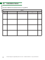
1
WyreStorm 4x4 Quick-Install
Matrix/receiver pack
(Version 2.0)
4 Input / 4 Output single-cable HD Matrix with IR Source control
Part Number MX-0404-QI
4 x Single Cat5e/6/7 40m (131ft) HD Receiver supporting
HDMI and IR Source control
Part Number RX-1UTP-IR-40
Instruction Manual
Thank you for choosing this WyreStorm product.
Please read these instructions carefully before installing to avoid complications later.
CONTENTS AND INTRODUCTION
Contents
1
Introduction
2
Features
i. MX0404-QI
ii. RX-1UTP-IR-40
3
Safety Precautions
4
Package Contents
5
Specification
i. MX0404-QI
ii. RX-1UTP-IR-40
6
MX0404-QI Panel Description
7
RX-1UTP-IR-40 Panel Description
8
Typical Application
9
Connection
10
Basic Operation
11
Advanced Operation
i. IR Call-back and Third Party Control Systems
ii. RS232 Control
iii. COM CTL
iv. LAN Control – NET CTL
v. MX0404-QI - EDID DIP Switch settings
vi. RX-1UTP-IR-40 - EQ Distance adjustment settings
12
Troubleshooting
13
FAQ
14
Maintenance
15
Provided Service
16
Mail In Service
17
Warranty
Warranty Limits and Exclusions
18
Installation Notes
1.
Introduction
The WyreStorm 4x4 Quick-Install pack (version 2) is a
system of HD switching and extension that comprises
of a 4 Input/4 Output HD Matrix together with 4 display
receivers that together provide a total solution for singlecable HD Distribution and Control over distances of up to
40m (131ft) in residential or commercial settings.
Time is money.
We all know it. Especially when it comes to HD installation.
Time saved in choosing the right combination of HD equipment
you know will work is just as important as getting it all up and
running as quickly and efficiently as possible so you can leave a
satisfied customer and move onto the next job.
We call this system ‘Quick Install’ because that is exactly what
you should expect; with great emphasis placed on reduced
installation time and an ease of connection that will enable the
installer to maximise their productivity on site, avoiding timeconsuming compatibility and configuration issues that can
unnecessarily prolong a project or in terms of installation time or
call-backs.
Specifically developed and manufactured to meet the needs
of the installer, the MX0404-QI is a dedicated system of HD
distribution and control, combining a 4x4 Matrix and four
single cable receivers – all of which of which are designed
work seamlessly together for complete compatibility and full
management of handshakes, screen resolutions and HD signal
distribution to each display point, whether in a residential or
commercial environment.
The MX0404-QI pack enables ANY four HD devices to be
viewed independently and simultaneously on ANY four displays,
with full 3D support over distances of up to 40m, with full control
of the connected sources as well as output from the matrix from
display locations via IR or RS232.
The system itself is entirely cabled on single Cat5e/6/7 UTP runs
to each display point throughout the location for the quickest,
most convenient and cost effective means of transmitting and
controlling full, uncompressed 1080p HD video and audio we
could think of to make sure your time on-site is as productive
(and brief) as possible.
Time is money. With the WyreStorm Quick Install pack in your
set up, you’ll have a little more of both.
NOTE For longer transmission distances, LAN control and
Ethernet pass-through, please see our full HDBaseT or
HDBaseT Class B range of matrices, transmitters, receivers and
extender sets.
For further information on this product and other WyreStorm
ranges, visit our website or download our latest product guide.
www.wyrestorm.com
2
Technical Support: [email protected] US: +1 866 677 0053 EU: +44 (0) 1793 230 343
• Protection against ESD (electrostatic discharge) included within
the unit to further stabilise transmission.
• LED indications for clear power and video signal selection.
2.
MX0404-QI
Features
• Quick and easy installation – set up in seconds straight out of
the box.
• Simplified ports - Input: HDMI – Output: integrated RJ45
connectors for a single Cat5e/6/7 UTP cable to each display
point for ease of installation.
• 5v mains supply included but receivers may be powered through the
USB port of the display using Wyrestorm USB to 5v power adaptor)
• Receivers capable of 1080p transmissions up to 40m
(131ft)
• ForUSB
even
greater control and fine tuning, each receiver
to 5V Cable
features
fully adjustable EQ distance range for
Part Number aCAB-USB-5V
optimising the transmission signal.
• Fully cascadable to further lengthen transmission.
• Protection against ESD (electrostatic discharge)
*NOTE: ideal conditions denote cable run is within
included
within
the
unitnotoelectrical
further stabilise transmission.
specified
distance
range of
product,
interference, the use of straight cable runs with no bends
• orLED
indications for clear power and video signal
kinks and no patch panels or wall outlets used. Please
be
advised that the presence of any of these factors in
selection.
your installation may compromise bandwidth and signal
• strength.
5v mains
supply
included
For longer
transmission
distances, RS232 control
Ethernet
pass-through, to
please
see our lengthen
full HDBaseT transmission.
• and
Fully
cascadable
further
MX0404-QI
• Conforms to IEEE-568B standards
• Each HDMI–port
alsoup
supports
DVI signals. straight
• Quick and easy installation
set
in seconds
• Each Output port can be fed to multiple displays (cascaded).
out of the box.
• Enables
up to 4 HDMI
video/audio devices
to be independently
• Simplified ports - Input:
HDMI
– Output:
integrated
switched through up to 4 HDMI displays or projectors for
RJ45 connectors for uncompressed
a single Cat5e/6/7
digital distribution. UTP cable to
• Each
outputof
ableinstallation.
to show any connected source simultaneously
each display point for
ease
regardless of whether the input carries HDCP encryption.
• Conforms to IEEE-568B standards
or HDBT Lite range of matrices, transmitters, receivers and
• Refined for Custom Install and Home Theatre Installations.
• Each HDMI port also supports DVI signals.
extender sets.
• Reads and copies EDID from connected devices with additional
• Each Output port canEDID
beconfiguration
fed to multiple
displays
through customisable
DIP switch settings if
necessary.
(cascaded).
• 2k resolution supported.
• Enables up to 4 HDMI video/audio devices to be
• Fully 3D compatible – Frame sequential 3D (Blu-ray) and
3. Safety Precautions
independently switched
through
up3Dto
4 HDMI
displays
interlaced
stereoscopic
(satellite
broadcasts
etc.)
• Supports all high definition
resolutions
up to and including
or projectors for uncompressed
digital
distribution.
1080p and standard video formats.
WARNING
WARNING
• Each output able to show any connected source
• RS232 port.
To reduce
risk of fire, electric
shock of fire, electric shock
Tothereduce
the risk
simultaneously regardless of whether the input carries
or product damage:
• Choose from 6 switching modes – infrared remote control, front
or product damage:
HDCP encryption. panel buttons, local IR, IR call-back, LAN and RS232.
1. Do not expose this apparatus to rain, moisture, sprays,
Simple switching
remote control
included, which can also be
• Refined for Custom •Install
and Home
Theatre
drips or splashes and ensure that no objects containing
learned into a universal remote handset to allow the control of
liquids
placed on the
apparatus,
including cups,
Installations.
1. Do
notareexpose
this
apparatus
to rain, moisture,
multiple devices from one handset.
glasses and vases.
• Reads and copies EDID
from
connected
devices
with
sprays,
drips
or
splashes
and
ensure
that no
• Fully compatible for integration with market leading control systems.
2. Do not place this unit in a confined space such as
additional EDID configuration
through
customisable
objects
containing
are Ensure
placed
• 4 x IR 3.5mm mini-jack
ports for
each output to link IRDIP
from
enclosed shelving,
cabinets liquids
or bookshelves.
the on the
control system to control display
unit is adequately ventilated.
switch settings if necessary.
apparatus,
including cups, glasses and vases.
• Additional infrared extension port for longer IR connections
3. To prevent the risk of electric shock or fire hazard due to
• 2k resolution supported.
overheating, do not cover the unit or obstruct ventilation
• HDMI v.1.3
openings
with material,
or
• Fully 3D compatible• –Supports
Frame
sequential
3D
(Blu-ray)
2.
Do
not place
thisnewspaper,
unit in cardboard
a confined
space such as
24Bit Colour depth
anything that may restrict airflow into the unit.
and interlaced stereoscopic
3D (satelClass B
enclosed shelving, cabinets or bookshelves.
• Signalling rate of 6.75 Gbps
4. Do not install near external heat sources such as
radiators, heat
or any deviceventilated.
that
broadcasts etc.)
Ensure
theregisters,
unit isboilers
adequately
• Pack comes complete with 1 x 4x4 Matrix with 19” rack
produces heat such as amplifiers or computers and do
brackets, 4resolutions
x 40m IR receiversup
with mounting
• Supports all high definition
to andbrackets, IR
not place near sources of naked flame.
receivers, emitters and a Matrix remote control handset.
including 1080p andAdditional
standard
video
formats.
3.
prevent
the
risk
ofsupply
electric
shock or fire hazard
5. To
Unplug
apparatus
from
power
during lightening
features included on the RX-1UTP-IR-40
storms or when unused for long periods of time.
• RS232 port.
due to overheating, do not cover the unit or
• Transmits one-way signal together with the HDMI signal over a
6. Protect the power cable from being walked on, pinched
single Cat5e/6/7
• Choose from 6 switching
modescable.
– infrared remote
obstruct
ventilation openings with material,
or restricted in any way, especially at plug connections.
• Receivers capable
of 1080p
transmissions
up to 40m
(131ft)
control, front panel buttons,
local
IR, IR
call-back,
LAN
newspaper,
cardboard or
anything
7. Only use attachments/accessories
specified
by the that may restrict
under ideal conditions*
manufacturer.
and RS232.
airflow
into
the
unit.
• For even greater control and fine tuning, each receiver features
8. Units contain non-servicable parts - Refer all servicing to
a fully adjustable
distance range for
optimising
the
• Simple switching remote
controlEQincluded,
which
can
qualified service personnel.
transmission signal.
also be learned into a universal remote handset to
4. Do not install near external heat sources such as
Technicalfrom
Support:one
[email protected]
677 0053 EU:
+44 (0)
1793 230 343boilers or any
4 device that
allow the control of multiple devices
handset. US: +866
radiators,
heat
registers,
• Fully compatible for integration with market leading
produces heat such as amplifiers or computers and
control systems.
do not place near sources of naked flame.
• 4 x IR 3.5mm mini-jack ports for each output to link IR
from control system to control display
5. Unplug apparatus from power supply during
• Additional infrared extension port for longer IR
lightening storms or when unused for long periods
connections
of time.
• HDMI v.1.3
• Supports 24Bit Colour depth
6. Protect the power cable from being walked on,
• Signalling rate of 6.75 Gbps
pinched or restricted in any way, especially at plug
• Pack comes complete with 1 x 4x4 Matrix with 19”
connections.
rack brackets, 4 x 40m IR receivers with mounting
brackets, IR receivers, emitters and a Matrix remote
7. Only use attachments/accessories specified by the
control handset.
manufacturer.
3.
Additional features included on the RX-1UTP-IR-40
• Transmits one-way signal together with the HDMI signal
over a single Cat5e/6/7 cable.
Safety Precautions
8. Units contain non-servicable parts - Refer all
servicing to qualified service personnel.
Technical Support: [email protected] US: +1 866 677 0053 EU: +44 (0) 1793 230 343
3
FEATURES AND SAFETY PRECAUTIONS
Features
FEATURES AND SAFETY PRECAUTIONS
2.
PACKAGE CONTENTS AND SPECIFICATION
4.
Package Contents
• 1 x MX0404-QI main unit
• 1 x Printed instruction manual
• 1 x Flash USB stick containing PC software and
digital copy of instruction manual. Digital copy also
downloadable from www.wyrestorm.com
• 1 x Matrix mounting brackets (pair)
• 1 x 12VDC power supply
• 1 x IR Extension cable (IR RX)
• 4 x IR TX Emitters (small for Input source)
• 1 x MX0404-QI remote control incl. battery (size/type:
CR2025 3V)
• 4 x RX-1UTP-IR-40 Display Receivers
• 4 x Receiver mounting brackets (pair)
• 4 x 5VDC power supply
• 4 x IR RX Receivers (larger for HD display)
5.
Specification
MX-0404-QI
Operating Temperature Range
-5 to +35°C (-41 to +95°C)
Operating Humidity Range
5 to 90 % RH
(no condensation)
Bandwith capacity/
Signalling Rate
6.75Gb/s
Input Video Signal
0.5-1.0 volts p-p
Input DDC Signal
12 volts p-p (TTL)
Maximum Single Link
Range
1080p 24Bit Colour
Transmission distance
HDMI: 15m (49ft) – if a
longer HDMI connection
is necessary, we offer the
WyreStorm in-line HDMI to
HDMI coupler
Video Format Supported
75.02
Power Supply
100-240V AC
Dimensions
440mm / 17.3” (W)
52mm / 2.05” (H)
235mm / 9.25” (D)
Weight
2 Kg / 4.4lbs
Rack space required
1U
RX-1UTP-IR-40
Operating Temperature Range
-5 to +35°C (-41 to +95°C)
Operating Humidity Range
5 to 90 % RH
(no condensation)
Bandwith capacity/
Signalling Rate
6.75Gb/s
Input Video Signal
0.5-1.0 volts p-p
Input DDC Signal
5 volts p-p (TTL)
Maximum Single Link
Range
1080p 24Bit Colour
Transmission distance
HDMI: 15m (49ft) – if a
longer HDMI connection
is necessary, we offer the
WyreStorm in-line HDMI to
HDMI coupler
UTP: 1080p signal up to 40m
/ 131ft (under perfect
transmission conditions.
Video Format Supported
VESA: 640x480,
800x600,1024x768,
1280x1024,1600x1200,
1920x1200
DTV/HDTV: 480i/576i/480p/5
76p/720p/1080i/1080p
Output Video
UTP: 1080p signal up to 40m
/ 131ft (under perfect
transmission conditions.
HDMI v1.3 + HDCP (mirrors
the input source to the output
display)
Output Audio
VESA: 640x480,
800x600,1024x768,
1280x1024,1600x1200,
1920x1200
DTV/HDTV: 480i/576i/480p/5
76p/720p/1080i/1080p
Fully supports DOLBY TRUE
HD AND DTS-HD (mirrors
input audio source to the
output)
IR Wavelength/Frequency
Wavelength
940 nm
Frequency
38khz
Dimensions
60mm / 2.4” (W)
115mm / 4.5” (H)
23mm / 0.9” (D)
Weight
0.15 Kg / 0.3lbs
Output Video
HDMI v1.2, HDMI v1.3
Power Consumption
22 Watts (max.)
4
BTU Rating (British Thermal
Unit)
Technical Support: [email protected] US: +1 866 677 0053 EU: +44 (0) 1793 230 343
MX0404-QI - Panel Description
FRONT
REAR
1
1
2
3
4
5
Mounting Brackets
2
Input select button (click to scroll numerically)
Input selection per output (click to scroll numerically)
3
4
IR Receiver port (IR RX)
5
AC100 – 240V power input
6
7
8
PANEL DESCRIPTIONS
6.
RS232 Port
LAN port (for control via the internet)
EDID DIP Switch
12V DC power input
IR RX extension port
Output ports (RJ45 Cat5e/6/7)
Input ports (HDMI)
IR TX Emitter ports (corresponds to inputs)
FRONT
4
1
2
3
2
3
8
REAR
5
1
7.
1
2
3
4
2
3
4
1
6
6
7
6
6
RX-1UTP-IR-40 - Panel Description
Power status LED (Lit when unit is powered)
Signal status LED (Lit when transmission is received)
5
6
7
Cat5e/6/7 connector
IR RX receiver port (placed on or near display/TV in
clear line of sight to remote handset used to control)
5V DC power input
HDMI out port (for display/projector)
EQ adjustment (fine-tuning signal to optimise
strength distance)
FRONT
1
2
3
4
REAR
EQ
MIN
MA X
P /N:R X-QI-IR -40
HDMI OUT
5
6
DIS TANC E
7
Technical Support: [email protected] US: +1 866 677 0053 EU: +44 (0) 1793 230 343
5
TPYICAL APPLICATION
8.
Typical Application
RX-1UTP-IR-40
40m (131ft)
P /N:R X-QI-IR -40
PS3/Xbox
RX-1UTP-IR-40
40m (131ft)
40m (131ft)
Cable/Satellite
P /N:R X-QI-IR -40
RX-1UTP-IR-40
MX0404-QI
Blu-ray/DVD
KEY
P /N:R X-QI-IR -40
IRTX Emitter
IRRX Receiver
40m (131ft)
HDMI
UTP Cat5e/6/7
Apple TV/Media Server
5m
Cat 5e/6
cable
performance
10m
15m
20m
25m
30m
35m
40m
P /N:R X-QI-IR -40
Single Cat5e/6/7 HD Display Receiver
RX-1UTP-IR-40
1080p
16ft
1080p
32ft
49ft
65ft
82ft
98ft
RX-1UTP-IR-40
114ft
131ft
1080i
Cat 5e Wiring Guide
The quality of termination for every RJ45 is essential. Poor
terminations leads to intermittent performance and longer install
times.
6
Technical Support: [email protected] US: +1 866 677 0053 EU: +44 (0) 1793 230 343
01
Connection
HDMI Source
02
Control
System
Additional
control via
RS232
12v DC power
03
IR TX jack plugged in to IR TX port of Matrix
Screen
MX0404-QI
KEY
LAN
IR TX emitter
placed over or near
infrared sensor
04
08
Cat5e/6/7 up to
40m (131ft)
IRTX Emitter
IRRX Receiver
05
HDMI OUT
MIN
LAN
MA X
EQ
UTP Cat5e/6/7
DIS TANC E
HDMI
5v DC power
07
P /N:R X-QI-IR -40
RX-1UTP-IR-40
1
Connect your HDMI input sources (such as: HDDVD,PS3/, XBOX360, satelClass B/cable, Blu-Ray etc.) to
HDMI inputs 1 – 4 of the MX0404-QI MATRIX.
Attention Do Not Hotplug! - Please insert and
extract cables carefully with the power SWITCHED
OFF. Connecting and disconnecting while the unit is
powered can result in damage to circuitry.
2
Attach the IR TX emitter sensor directly over the
infraredreceiving area of the input source using the
adhesive backing. You may need to adjust the position
of the emitter after installation to achieve the best results.
Sometimes moving the sensor to different areas of the
source facia can improve IR performance.
3
Plug the 3.5mm jack of the IR TX emitter into your
chosen number IR TX port on the rear panel of the
MATRIX.
HINT Locate the infrared sensor on devices by
shining a flashlight onto the display panel of sources
and look for a small sensor.
4
Connect a good quality, well terminated Cat 5e/6/7
cable with an RJ45 connector wired to 568B standard
at both ends from the UTP Out port of the MATRIX to
the UTP IN of the RX-1UTP-IR-40 DISPLAY RECEIVER.
06
IR RX receiver placed discretely on the
display with a clear line of sight to the
infrared remote control being used
Ensure both connectors are pushed securely into each
port and supported by the connector strain relief clip
to prevent them from becoming loose. The quality of
termination for your RJ45 is essential. Poor quality
terminations lead to intermittent performance and longer
install times.
Attention We strongly recommend using the
supplied mounting brackets to secure the MATRIX
and the accompanying DISPLAY RECEIVER baluns.
Any sudden movement of these devices could lead
to loss of picture and sound if connections become
loose or strained, resulting in unnecessary service
call backs.
5
Connect the HDMI OUT of the DISPLAY RECEIVER
to the HDMI IN of the display.
6
Plug the 3.5mm jack of the IR RX receiver into the
IR RX port of the display receiver balun. Place the IR
RX receiver sensor discretely on the front of the display
with care taken to achieve a clear line of sight with the
remote control to be used. Again, you may need to adjust
the position of the receiver to achieve the best signal
reception.
7
Connect the DISPLAY RECEIVER balun to the 5v
power adaptor (included with the receiver)
Technical Support: [email protected] US: +1 866 677 0053 EU: +44 (0) 1793 230 343
7
CONNECTION
9.
8
BASIC OPERATION
Switch on the power to your input sources, displays,
and any display receivers used. Finally, power up the
MATRIX. Your MX0404-QI should now be fully connected
and ready for use.
Remember, always switch off the matrix before
unplugging any inputs or outputs – follow last on, first off
protocol.
If there is electrical interference or cable bends/kinks
within the set up the IR is one of the first functions to fail.
If you do not have IR control:
• Check your cables are straight with jacks firmly
connected to ports. • Check your IR sensors are
unobstructed and able to receive infrared signals.
• Check direct sunlight on the emitters/receivers is not
affecting the infrared signal.
9 If your IR emitters and receivers are correctly placed
you should now be able control your sources from each
individual display location.
10.
Basic Operation
Front Panel Control
Basic switching of various source inputs to output
displays can be achieved via the front panel control of the
MX0404-QI.
Outputs are numbered 1 – 4 with an input select button
to the left. Repeated pressing of the select button of a
specific output scrolls through the HDMI input devices
connected to the matrix, with the corresponding LEDs
illustrating when a device has been selected for that
particular output. The chosen input will automatically
store for the output so, even when the matrix is powered
off and on, on resumption the last selected input/output
combination will remain.
Attention Users will notice a brief flicker on
screen when switching between inputs/outputs
– this is normal for this model and represents the
matrix resetting device HDCP settings to allow
communication from a different device. For constant
HDCP when switching with no noticeable screen
resets, see WyreStorm PRO, Pro Plus and HDBaseT
matrix ranges. See www.wyrestorm.com for more
information
Remote Control (Local IR)
Select specific
source numbered
1-4
1
1
2
3
2
3
Output port number
4
2
1
Toggle numerically
forwards/backwards
through connected
source devices
To change handset
battery
4
3
1
2
3
4
4
1
2
3
4
Pinch here and pull out
Install battery ‘+’ side up
and only use CR 2025 3V
batteries. Slide
compartment back into
the handset.
The same basic functions can also be accessed via the
remote control. Operation of the handset is the same
regardless of location – locally (source/IR emitter) or
remotely (display/IR receiver).
Simply toggle through the input sources connected to the
matrix by either pressing the left/right arrow buttons or
buttons numbered 1 – 4 for each output.
8
Technical Support: [email protected] US: +1 866 677 0053 EU: +44 (0) 1793 230 343
The MX0404-QI is not only a switcher and extender of
multiple HDMI signals to multiple HDMI receivers located
remotely, it also passes IR control signals through the IR
call-back system to the matrix and HDMI sources for full,
independent control of all connected inputs from output
locations using your remote handset.
HDMI Source
HDMI Input 1
IR TX 1
HDMI Input 2
IR TX 2
HDMI Input 3
IR TX 3
HDMI Input 4
IR TX 4
IR Path
IR Receiver
1
UTP Out 1
UTP Out 2
UTP Out 3
UTP Out 4
1
2
3
1
2
3
1
2
3
4
2
Cat5e/6/7 up to
40m (131ft)
4
4
1
2
3
4
As each IR TX port is allocated to an individual HDMI
input port, if the user is unable to establish IR control of
the device, care should be taken to check that, firstly,
the IR emitter and HDMI input ports match (Input 1-TX1,
Input2-TX2 etc.) with plugs secured in correct ports,
and secondly, that the IR TX emitter sensors are firmly
attached directly to the front of inputs and covering
infrared sensor windows of the source devices.
Some later adjustment may be needed to the location
of the sensor to achieve the best performance results sometimes moving the sensor to different areas on the
source can improve IR performance.
HINT Infrared receiving areas of devices can be
located by shining a flashlight onto the front of
the device – the sensor should be able to be seen
through the plastic as a small, round object inside.
P /N:R X-QI-IR -40
IR Receiver
4
3
IR Path
HDMI Cable
is added to the HDMI of the input device so, for example,
if the user is watching Blu-ray on input 3, the IR signal
will be directed through the IR TX3 socket to control the
device.
1
1
2
3
1
2
3
1
2
3
1
2
3
4
2
4
3
IR Path
Output Display 1
4
4
4
This is accomplished by placing a series of IR Emitters on
source devices you wish to control and IR Receivers at all
output locations you wish to control from to enable the IR
control signal to be delivered via single Cat5e/6/7 cable
connecting the two.
RX-1UTP-IR-40
2
P /N:R X-QI-IR -40
E QRX Receiver jack into
At display end: Insert the IR
MIN
the IR RX port of the RX-1UTP-IR-40 receiver baluns,
MA X
with the IR receivers themselves
placed in clear view on
or near the displays
to
receive
an
infrared
signal from the
HDMI OUT
DIS TANC
E
remote handset used to control inputs.
Fasten firmly to the surface to avoid displacement.
Attention Misplaced or poorly secured IR Emitters
1
At Matrix end: Insert the 3.5mm jacks of the IR TX
Emitters included with the unit into the IR TX Emitter ports
at the rear of the matrix according to input. The IR signal
and Receivers may result in intermittent IR control
signals passed to and from the matrix. Check your
placement and adjust if necessary.
Technical Support: [email protected] US: +1 866 677 0053 EU: +44 (0) 1793 230 343
9
BASIC OPERATION
IR Call-back of Matrix and Source Devices
ADVANCED OPERATION
HINT If problems are encountered controlling
devices remotely, check IR TX Emitters and IR RX
Receivers are correctly positioned and connected
to sources, displays and display receivers, with all
devices fully powered and the matrix set to IR callback enabled and IR TX Switch mode activated.
See COM CTL section for Call-back enabling.
IR Extender Control
Front Panel
1
1
2
3
Output port number
4
Output1 source select key code:
0x80 0x81 0x82 0x83 0x84 0x85 0x86 0x87
2
1
2
3
1
2
3
1
2
3
4
Output2 source select key code:
0x90 0x91 0x92 0x93 0x94 0x95 0x96 0x97
3
Output3 source select key code:
0xa0 0xa1 0xa2 0xa3 0xa4 0xa5 0xa6 0xa7
4
4
X
Toggle numerically
forwards/backwards
through connected
source devices
Select specific
source numbered
1-4
Output4 source select key code:
0xb0 0xb1 0xb2 0xb3 0xb4 0xb5 0xb6 0xb7
4
Rear Panel
Should local control of the Matrix
via the front panel IR sensor be
an issue, for example if the
sensor is obstructed or the unit
is installed in a closed area out of infrared line of sight,
the IR RX Receiver included with MX0404-QI can be
inserted into the IR EXT port at the rear to extend the IR
sensor range and enable local control of the matrix.
11.
Advanced Operation
Typically, unless alternative methods of controlling the
matrix are chosen or problems with device communication
through the matrix encountered, basic operation is all
that is required to operate your MX0404-QI. However, the
following information on advanced operation will detail
how the matrix system can be configured for advanced
control and settings altered or data manually input should
such problems arise, as well as configuring the system for
third party control.
IR Call Back and Third Party Control systems
Attention Due to the differing method of control
based on location, if you are using a third party
control system, learning the control from the IR
is NOT recommended as control will be limited to
scrolling up/down between inputs. For discrete
source selection you will need to import discrete
hex codes for control systems. These can be
obtained through the WyreStorm website, by
contacting our technical support or you can input
them manually.
NOTE The IR is NEC and possesses a carrier wave
of 38KHz with a system code of 0x00
10
RS232 Control
Control of the matrix is possible through RS232 using
third party control systems or the dedicated WyreStorm
COM CTL software included with your purchase (also
downloadable from www.wyrestorm.com).
Should third party control be required, please see below
for control system configuration and hex code input. The
RS232 connection on the matrix is female QB9.
Users can use a USB to RS232 cable or a direct male to
female serial cable.
5
4
Ground
3
1
RXD TXD
7
6
Female connector - 9 holes
1
2
3
4
TXD RXD
6
RXD Receive serial data from PC
TXD Transmit serial data to PC
Com Port Setting
8
9
2
7
8
5
Ground
9
Male connector - 9 holes
Baud rate
9600bps
Data bits
8bits
Parity
None
Stop bits
1
Flow control
None
COM CTL
Control of matrix switching and system settings is
possible using the WyreStorm COM CTL software
included with your purchase.
After fully connecting all inputs and outputs to the matrix
and installing the software, on opening the program
the control window will display information from the
matrix, such as messages received from the switch such
as input/output details, firmware version and control
commands/HEX codes that allow the system to be
controlled remotely, as well as buttons used to navigate
the screen.
Technical Support: [email protected] US: +1 866 677 0053 EU: +44 (0) 1793 230 343
ADVANCED OPERATION
9
6
7
8
1
2
3
4
5
1
Receive Message Window – displays messages
received from the matrix, such as input/output settings
and command selections.
You can view the current condition of all input/output
ports by pressing the
button.
Pressing
will delete the previous message received in the window.
2
Send Message Window – Input your serial
commands for the matrix in the Send Message Window such as instructions for outputs or to enter update mode
– and click the Send button to deliver the message to the
Matrix. The control command uses ASCII.
Press Enter, then Send Message
to put the matrix into firmware update mode.
Press the Connect 5 button and run the firmware.
When the firmware has finished updating, press the same
button again to Connect and powercyle the matrix (turn
off and on).
Updates are now active and the firmware is now updated.
Attention To see the firmware version currently
used in the system – power off and repower while
the matrix is connected to COM CTL. The firmware
version and creation date will be displayed together
with the normal output state of the matrix.
RS232 Control
3 Com Connect State – Shows if the matrix is
connected or disconnected to the Com Port and
communication is enabled. Selection between ports is
available by pressing the Com Port Select button.
Code: ICP BE 7C 5F
When connected, the only option will be to Disconnect
and vice versa. Press 5 to connect/disconnect the
matrix from the software control.
To update the system firmware, enter the following code
into the Send Message Window, ensuring to include one
space between each section of the code.
Technical Support: [email protected] US: +1 866 677 0053 EU: +44 (0) 1793 230 343
11
ADVANCED OPERATION
• Connected to ENABLE matrix communication
• Disconnected to DISABLE matrix communication
4
Com Select
5
Connect/Disconnect
3
to manually input the IP address.
4
Click
to complete the process or
Click the Com Select dropdown to see all Com ports
available. Select your chosen Com port number and press
the CONNECT button. You will notice the button change
to show ‘disconnect’ and CONNECT STATE change
to green for ‘connected’. Pressing the button again will
disconnect the Com port and the CONNECT state will
show red.
NOTE The Com Select drop box offers options of
Com Ports to connect to – COM 1-10
6
Set IP Button – allows you to set the IP address to
be used by the system.
The matrix can also be controlled over LAN. Selecting
the Set IP button 6 in the main COMCTL screen allows
access to IP functions that obtains and stores IP address
information necessary for LAN control.
to exit and return to the main screen.
NOTE To access matrix control over LAN, enter the
IP address of the matrix into your internet browser
and you will be directed to the web control screen.
For full information on LAN control, see NETCTL section
of this manual.
7 UTP Set – Default setting is OFF for normal Matrix
operation to obey device EDID/HDCP commands and
high hotplug settings when outputting a signal.
Switching output settings to ON instructs the matrix
to output a signal regardless of device EDID/HDCP
or hotplug data – such information is circumvented to
encourage communication in the event of problems
between sync devices.
We recommend this setting for system debugging by the
installer and not for operation by the end user.
8
IR Matrix – IR Matrix - allows specific SOURCE IR
ports to be manually set to individual DISPLAY ports to
configure specific IR configurations through the matrix.
This function is available only when the matrix is
connected to receivers via UTP and all units fully powered.
1
2
3
4
Clicking opens a pop-up window in which you can
choose to let the system automatically detect your IP
address, with the result displayed in the box below.
Alternatively, if the system cannot detect an IP address,
select ‘Use the following IP Address’ and you can add
manually.
1
2
1
3
4
Selection enables the IP address to be obtained
automatically, with the result appearing in the white box
below.
IR Matrix allows manual selection of source device
ports 1
by Display Receiver ports 2
2
The dropdown menu 3
allows ALL IR TX ports to be
set to ONE specific INPUT device IR RX port with the
Should no address appear or if the system is unable
to detect an IP address, select option
12
Technical Support: [email protected] US: +1 866 677 0053 EU: +44 (0) 1793 230 343
ADVANCED OPERATION
current settings of the IR Matrix viewable by pressing the
button 4
9
Input/Output Switch – Switches connected inputs
per output.
COM CTL
Input/Output selection
Operation as with remote control handset – select the
chosen input to be displayed on each output by either
clicking the left/right arrow buttons to scroll through inputs
numerically, or pressing the input number 1-4.
A large yellow number denotes each OUTPUT section
with INPUTS chosen by either clicking the left/right arrow
buttons to scroll through inputs numerically or by pressing
the input numbers below.
The INPUT/OUTPUT switch allows output port selection
(display) and Input port select (source) buttons for specific
combinations of displays and sources within the matrix.
NETCTL - LAN Control
The matrix can also be controlled via LAN over a network/
web browser using the supplied WyreStorm NET CTL
software or LAN protocols from third party companies,
such as Control 4 and TELNET Control for all control
systems.
As with COM CTL, install the NET CTL software included
with the matrix (also downloadable from www.wyrestorm.
com) and run the program by double-clicking NETCTL.
exe
Attention Use a ‘straight through’ ethernet cable
for switch/router connection and a ‘cross-over’
cable for connection to a PC. Using the incorrect
cable will not damage your equipment, but it may
result in poor/no connection.
Make sure that your LAN cable is correctly
terminated and firmly connected to ports before
running the software.
On initial opening, the program will first create a NETCTL.
TXT file that will serve as a device backup for future use;
including connection settings such as IP address and
MAC address of the MX0404-QI, as well as its name if
you decide to change the name of your matrix (see Device
Name section below).
On subsequent openings, NETCTL will then search the
Matrix for the saved data required for connection.
If using for the first time, the program will automatically
detect the IP address being used, with the result
displayed in the white area beneath.
Should no result appear or if the system is unable to
detect an IP address automatically, press the
button to locate.
When the IP address appears, click
to attach the IP address to the system and the IP address
will change to a default factory serial number MX0404-QI
or MX0404-HDC.
Device Name
Should you wish to change the name of your matrix from
the factory default, just right click on the serial number
and select ‘rename’ from the dropdown menu. Input the
new name and press OK.
Technical Support: [email protected] US: +1 866 677 0053 EU: +44 (0) 1793 230 343
13
ADVANCED OPERATION
Double click on the device name/default factory serial
number (or right click and OPEN) and you will be directed
to a web login page in your internet browser.
Press the
button to update your chosen matrix settings into the left
hand display and your selection to take effect.
B
The lower section of the NETCTL controller screen is
dedicated to IR Matrix settings.
As with the IR Matrix screen in COMCTL, the NTCTL IR
Matrix allows specific SOURCE IR ports to be manually
set to individual DISPLAY ports to configure specific IR
configurations through the matrix.
Press the
for IR Matrix changes to be set.
This function is available only when the matrix is
connected to receivers via UTP and all units fully powered.
TELNET Control
Control of matrix switching and system settings are also
possible using Telnet control protocols. Follow system
commands below.
Enter the default password of ten zeros ‘0000000000’
and click
to take you to the NET CTL matrix controller screen.
A
B
A
The layout of the NET CTL controller screen includes
an upper section to allocate input sources to output with
the selection displayed on the left hand side.
Operation is the same as COM CTL – Inputs buttons 1-4
can be clicked to be selected per Output port.
14
Assign IP
If ‘Assign IP’ is displayed in the dialog box, the matrix has
encountered a
problem detecting
an IP address and
manual input of
information is
required. In such
instances, double
click ‘Assign IP’ or
right click and
choose Assign IP
from the dropdown
menu to add details
as required.
Technical Support: [email protected] US: +1 866 677 0053 EU: +44 (0) 1793 230 343
ADVANCED OPERATION
Click
to assign the new IP address to the system and you will
return to the previous screen or
to return without changes taking effect.
Now click
for the Matrix to detect the new IP address, which will
appear in the dialog box. Finally click
to confirm IP settings
Attention This ‘Assign IP’ process differs from the
COM CTL ‘IP Set’ function.
‘Set IP’ in COMCTL saves/reads the IP address
in flash and sets it as static IP. ‘Assign IP’ is only
used when the system fails to obtain an IP address
automatically and is NOT saved in flash.
MX0404-QI - EDID DIP Switch setting
Distribution of HD signals through the matrix requires
mutual communication or ‘handshake’ between source
and display. If there is any disparity between the two,
successful transmission becomes problematic.
This matrix comes equipped with an EDID DIP switch on
the rear panel for manual adjustment of matrix settings to
encourage communication between INPUT and OUTPUT
devices. If installation compatibility issues arise, check the
settings on your connected devices and adjust the DIP
settings as required.
Attention Changes to the DIP switch settings
should be made with the matrix OFF, ideally with
all power cables and HDMI leads and UTP cables
removed to guard against electrostatic build up that
may damage your system. DO NOT HOTSWAP your
cables when changing DIP SETTINGS.
ALL changes to the DIP settings become effective
upon powering ON the matrix.
EDID Copy from Output display to Input
port (Force Signal Output mode)
To copy the EDID from an OUTPUT display
to a specific INPUT port, first set the DIP
switch to this position. Then select the INPUT by pressing
and holding the chosen OUTPUT SELECT button for 3
seconds for the EDID to be copied from the DISPLAY to
the INPUT port.
Select the INPUT you wish EDID to be copied onto.
PRESS and HOLD the OUTPUT SELECT button for
3 seconds for the OUTPUT EDID to be copied to the
selected INPUT
1080p 3D Video / Stereo Audio (using
embedded M-series EDID) FACTORY
DEFAULT
Setting the DIP switch to this position will
instruct the matrix to use embedded 1080p 3D video
and Stereo audio to encourage communication between
the matrix and 3D sources/3D displays if handshake
problems are encountered.
After setting the DIP switch, reconnect and turn on for the
changes to take effect.
RESETTING TO FACTORY DEFAULT:
As 1080p-3D-Stereo is the default factory setting for the
matrix, to reset EDID of all ports, simply set the DIP switch
to the above position when the matrix is powered OFF. On
powering ON, all ports will revert to 1080p-3D-Stereo and
DIP switches can be adjusted as necessary.
1080p Stereo (using embedded A-series
EDID)
The matrix will use embedded 1080p video
and stereo audio in this DIP setting.
After setting the DIP switch, reconnect and turn on for
EDID settings to take effect.
1080i Stereo (using embedded L-series
EDID)
In instances where a connected display is
unable to achieve 1080p resolution (such
as using older or cheaper models), this DIP setting will
instruct the matrix to use embedded 1080i video and
stereo audio to output a signal.
After setting the DIP switch, reconnect and turn on for
EDID settings to take effect.
Technical Support: [email protected] US: +1 866 677 0053 EU: +44 (0) 1793 230 343
15
1080p 5.1 Audio (using embedded
D-series EDID)
ADVANCED OPERATION
When set to this DIP position the matrix will
use embedded 1080p video with 5.1ch
Audio. After setting the DIP switch, reconnect and turn on
for EDID settings to take effect.
1080p 7.1ch Audio (using embedded
G-series EDID)
When set to this DIP position the matrix will
use embedded 1080p video with 7.1ch
Audio. After setting the DIP switch, reconnect and turn on
for EDID settings to take effect.
Attention Please ensure the balun is switched
OFF when changing the dial to desired distance
setting.
AVR 7.1 Audio EDID COPY to Blu-ray source (AV
Receiver copy)
R
RX-1UTP-IR-40 - EQ Distance Adjustment Settings
Occasionally, the installation environment, such as the
distance between source and display may be a factor in
the perfect transmission and reception of a signal.
In addition to the MX0404-QI LONG CABLE settings on
the Matrix DIP switch, the EX-1UTP-IR-40 RECEIVER
balun can be further fine tuned depending on the length of
Cat5e/6/7 cable used for optimum performance.
RECEIVER
5
6
7
4
0 1
Changes become effective when turned back ON.
For users who wish to copy EDID from an AV Receiver
with 7.1 channel audio to a specific input port containing
EQ
EQ
EQ
a Blu-ray 2player, follow a variation on the instructions
3
MIN
MIN
MIN
above:
MA X
MAX
MAX
1. Set
the DIP switch to the above position with the matrix
HDMI OUT
DIS TANC E
-40
in the
OFF position.
HDMI
HDMI
HDMIOUT
IN
HDMI OUT
OUTP /N:R X-QI-IR
DISTANCE
EDID
DISTANCE
2. Connect the AVR to your desired OUTPUT port on the
matrix (for example, OUTPUT 2)
Position Functions
3. Power ON the matrix and select your INPUT on the
0
0-5m Transmission distance
AVR, making sure your chosen SOURCE is connected
1
5-10m Transmission distance
to (for example, INPUT 3 – Blu-ray)
2
10-15m Transmission distance
4. Press and hold the OUTPUT SELECT button for 3
3
15-12m Transmission distance
seconds for the EDID data to be copied from OUTPUT
4
20-25m Transmission distance
2 (AVR) to INPUT 3 (Blu-ray).
Remaining settings no function (reserved for future
updates)
5
25-30m Transmission distance
6
30-35m Transmission distance
7
(default)
35-40m Transmission distance. Default position 7 recommended
for initial connection and operation. If signal requires fine-tuning,
move through the following settings until desired image quality is
achieved.
8 to F
No function - settings reserved for future updates
TV2
TV2
TV2
TV2
Support 1080i stereo
Video: 1080i
Audio: stereo
Video and Audio:
unsupported
Video: unsupported
Audio: stereo
TV1
TV1
TV1
TV1
Support 1080P stereo
Video: 1080i
Audio: stereo
Video: 1080P
Audio: unsupported
Video: 1080P
Audio: stereo
INPUT
OUTPUT
2
2
Support 1080P7.1 Audio
AVR
16
2
2
Video: 1080i
Audio: stereo
Video: 1080P
Audio: 7.1
Video: 1080P
Audio: stereo
Fix EDID
1080i-2CH
DIP: 001
Copy AVR’s
EDID
DIP: 001
Copy Tv1’s
EDID
AVR
AVR
AVR
Technical Support: [email protected] US: +1 866 677 0053 EU: +44 (0) 1793 230 343
Generally, the majority of HD distribution installation
issues are either caused by minor connection
errors, communication problems between devices,
or when the transmission of high signal bandwidth
is attempted using insufficient cable. Should you
encounter any technical difficulties when installing
and configuring the matrix, we are confident
solutions can be found by working through the
following troubleshooting checklist before seeking
alternative technical support.
4) Cable joins? Joins in your cable run can impact on
signal strength, resulting in reduced transmission that may
manifest itself in poor picture quality or a complete lack of
picture.
12.
No Picture or poor quality picture
1) Power – are your HDBaseT transmitter or display
receiver baluns powered both ends? Transmitters and
receivers should have their own power source i.e. the 5v
power adaptors included with your baluns.
Are all sources definitely powered and firmly connected?
2) If possible, always use test equipment prior to
installation and to troubleshoot any problems.
5) Signal Reduction – Are you using stranded patch
leads as interconnects between patch panels or
wall outlets? Such use reduces signal strength – we
recommend solid core straight through connections to be
used wherever possible.
6) Resolution – If you reduce the resolution of the source,
do you get a picture? If so, this suggests a discrepancy
between source and display resolution or a bandwidth
capacity issue with your cable. Check that your inputs and
outputs share the same resolution and that the signal is
being successfully transmitted along your cable run.
7) Correct connection – It may seem obvious but
double check all UTP, HDMI, power and IR cables are
connected to the correct ports. Even a fraction off can
be the difference between a perfect picture and a blank
screen. Double check all connections are firmly made in
the correct ports.
9) Cable wired to 568B standard? Is your cable wired
and terminated correctly and are those terminations
connected to the correct ports?
Test Monitor
Part Number
TTMONITOR
Signal Generator
Part Number
TTSIgnal
3) Distance – Is your cable too long for the signal
to be transmitted effectively? The QI System allows
transmission of 1080p up to 40m (131ft) so make sure
you cable distance matches your requirements and is well
within the maximum transmission distance of the signal.
10) Electrical interference – HD transmissions are
susceptible to electrostatic interference so locations of
cables and devices should be considered
11) Do you get a picture if you connect the source
directly to the display? If not then the problem could lie
with the input or output device rather than the means of
distribution i.e. the cable or matrix itself.
12) HDMI lead condition and quality – HDMI cables
and connectors are delicate and can be damaged much
easier than component or coax cable. Furthermore,
lead quality varies dramatically, particularly in lower price
brackets. Swap your HDMI leads and check operation –
damage to or quality of your leads could be the problem.
If in doubt, swap them over. Always take care inserting
and extracting your HDMI from matrix ports so as not to
damage the connectors or ports.
13) Picture snow/HD ‘noise’ – represents a poorly
established signal that may be caused by poor quality
Technical Support: [email protected] US: +1 866 677 0053 EU: +44 (0) 1793 230 343
17
TROUBLESHOOTING
Troubleshooting
Note: If you are approaching the limits of the transmission
capabilities, you will need to use a WyreStorm Extender
set for the signal to transmit effectively.
TROUBLESHOOTING
terminations or excessive cable lengths. Try swapping the
display adaptors from a location you know is functioning
properly or swapping the outputs of the matrix switch
used.
If the problem remains on the same screen this may be
caused by a connection problem between matrix and
display – turn off all equipment and swap the signal
carrying cables at both ends to ascertain if the cable or
termination is at fault.
14) Blu-ray: Deep Colour – make sure Deep Colour is
turned on in your Blu-ray settings and displays.
15) Blu-ray: Resolution – if a reduction of resolution to
720/1080i produces an image, cable issues such as
interference, patch panels, wall outlets, stranded cable
use or excessive cable length are likely restricting
transmission of a full 1080p signal.
16) Blu-ray: 3D – is the equipment used 3D enabled/
compatible? Is a 3D disc being played in a 3D enabled
Bluray player or through a compatible amplifier?
17) Colour distortion – a pink or green screen indicates
an incompatibility between colour spacing formats – the
commonly used RGB or YUV used by older displays.
Some sources allow switching between RGB and YUV
which may solve any colour problems. If not, try changing
the HDMI cable between the source and the matrix to rule
out defective cabling.
Audio is transmitted within the video signal – there
is no separate audio track – so generally a problem
with sound will be accompanied by a problem with
picture. However, if technical issues with audio are
experienced, the cause is typically communication
between sources, displays and/or AV receiver
settings.
No sound or poor quality audio
2) Consistency of audio output between devices – Is
there any discrepancy between the audio output of the
source, the audio or zonal settings of the AV receiver and
the speaker configuration used needed for successful
audio replication? If you are outputting 7.1, make sure all
devices connected are also outputting 7.1
Note: Occasionally with some sources, the device
settings allow the specification of audio output through
a TV or an HDMI port. If using an AV receiver, check the
HDMI output option is selected.
3) Do all the local sources work through the AV
receiver?
Check the operation of each source individually.
Bandwidth
1) If using a graphics-based source (such as a PC/Mac/
media server), make sure the source resolution is set to
a maximum of 1080p, 50Hz. Higher resolutions available
for graphics-based systems require higher bandwidth
that may affect transmission of signals as well as
incompatibility with devices.
IR
1) Check you are using emitters at the IR TX
transmitter end and receivers at the IR RX receiver
end – are they connected to the correct ports on the
matrix and display receiver.
2) Is the emitter correctly positioned on the source?
Fix the emitter directly over the infrared sensor of the
source and attach using the adhesive backing.
Note: Locate the infrared source sensor by using a
flashlight to find s small sensor within the facia of the
source display. If necessary, secure the emitter over the
sensor with a small amount of contact adhesive.
1) If using an AV receiver, check your source input
assignment – do you have specific speaker sets or zones
enabled? Some AV receivers allow individual speaker
selections assigned to specific zones in the set up so
check the speakers used are fully connected to the
amplifier and correctly assigned within the system set up.
3) Is your remote powered and sending a signal?
IR is invisible to the naked eye, so use a digital camera/
phone camera to check the remote signal – point the
camera at the remote control when pressing a button. You
should see the remote transmitter flashing to indicate a
signal being sent. Replace batteries if flashing is not seen
on the digital camera screen.
Note: If you experience problems when an AV receiver is
used, the cause is usually the settings of the AVR itself.
Refer to the AVR manufacturer’s guidelines on the correct
settings to use for your requirements.
4) IR dropout issues can be due to exterior influences
emitting infrared radiation that can interrupt IR signals.
Ensure emitters and receivers are away from the following
causes of IR interference.
18
Technical Support: [email protected] US: +1 866 677 0053 EU: +44 (0) 1793 230 343
5) UTP Termination Issues - swap cables over at
both transmitter and receiver ends to see if control is
established. If so, a possible re-termination of the cable
could remedy the problem.
6) Are you using WyreStorm emitters and receivers?
The use of third party products/magic eyes may not be
compatible. Always use WyreStorm components included
with your purchase or check compatibility of third party
control systems with your WyreStorm dealer.
7) If problems persist, swap out the IR emitters and
receivers to rule out faults with the units themselves. Use
emitters you know are fully operational to test working
condition.
8) Reactivate the IR callback function on your matrix and
swap IR ports on the matrix to rule out a fault with the
matrix or connection ports.
9) Should IR remain unresponsive, turn off and
disconnectall cables from the matrix and reconnect zones
one at a time to assess if one location in particular is the
problem. If so, run new cables directly to the display – if
this fixes the problem, it is likely that electromagnetic
interference /damage to the cable somewhere along the
run is causing the IR signal to drop out. Investigate and
remove EM interference from the run or replace damaged
UTP cable.
13.
FAQ’s
5e or 6?
While our equipment is tested and graded to Cat 5e
cable standard; tests have shown that better results
are achieved when using Cat6 cable. The lower gauge,
thicker copper cores ensure better signal transfer.
Newly installed cabling should always conform to Part P
Regulation and BS 7671 (17th Edition), and should be
terminated to 568B standard
Can I use a single Cat 5e cable?
Although conventional transmission is considered to be
two Cat5e cables, it is possible to send the signal down
a single cable if necessary. All of our pro-matrix switches
and UTP splitters support single UTP mode, however in
this mode IR control of sources and matrix switching is
not possible.
However using HDBaseT transmission; all of the twin
cable features are supported with the added benefit of
Ethernet and RS232 control.
How far can the signal travel?
Under perfect transmission conditions our HD receivers
will operate at 30, 50 or 100m (@1080p) depending on
the model used. Perfect conditions mean no electrical
interference, straight cable runs with no bends or kinks
and no patch panels or wall outlets. If some of the above
are factors in your installation then signal strength and
bandwidth can be compromised. If a cable run is reaching
the upper limit of the receivers’ capabilities, then the
signal can be boosted by way of an extender set (Rx TX)
or by simply using an in-line repeater. Our transmission
signals can be repeated up to 5 times (250m) using
a conventional TMDS signal or 7 times (700m) using
HDBaseT technology.
What about 3D?
All of our matrix switches and most of our extender
products will pass-through a 3D Blu-ray signal. The 30m
and Coax extender sets do not support frame sequential
3D (Blu-ray), but will still pass-through interlaced stereoscopic 3D (Satellite etc.)
How do I control the sources?
Most of our HDMI distribution products support some
kind of IR pass-through from point-to-point extender sets
to pro and HDBaseT matrices. Most of the range now
supports wideband IR meaning it is compatible with any
IR device available on the market. Our Pro and HDBaseT
matrix range (Cat 5e) has IR pass-through from each of
the outputs and has discrete IR outputs at the switch end,
meaning you can have multiple identical sources yet the
IR would be routed only to the applicable source.
Do I need power at the TV end?
Yes. Our HD display adaptors require a 5v power supply
at the TV end to operate. It’s important that these are
powered locally and do not receive remote power from
the rack as there can be issues resulting from voltage
drop along the length of cable.
Are WyreStorm products compatible with
HDMI 1.4?
HDMI 1.4 refers to a list of ‘features’ that a device is
capable of supporting, including Ethernet channel, return
audio channel, 3D etc. Due to the continuously evolving
nature of the technology, HDMI Licensing LLC have now
decided to simplify terminology by testing and referring to
cable in terms of STANDARD or HIGH-SPEED rather than
Technical Support: [email protected] US: +1 866 677 0053 EU: +44 (0) 1793 230 343
19
TROUBLE SHOOTING AND FAQ’S
• Direct sunlight
• Halogen lighting
• Plasma screens
MAINTENANCE, PROVIDED SERVICE AND MAIL-IN-SERVICE
in generations 1.3, 1.4 etc.
• STANDARD (or “category 1”) HDMI cables perform
at speeds of 75Mhz or up to 6.75Gbps, which is the
equivalent to a 720p/1080i signal.
• All WyreStorm equipment support HIGH-SPEED
(or “category 2”) HDMI cables that have been tested
to perform at speeds of 340Mhz or up to 10.2Gbps,
which is the highest bandwidth currently utilised over
an HDMI cable and can successfully handle 1080p
signals including those at increased color depths and/
or increased refresh rates from the Source. High-Speed
cables are also able to accommodate higher resolution
displays, such as WQXGA cinema monitors (resolution of
2560 x 1600).
What about screens with different
resolution capabilities?
When sending a signal point to point a TV will
communicate it’s capabilities to the source, then the
source will output a suitable signal that compatible (i.e.
1080p Stereo audio). If you were to use a matrix switch
with three 1080p screens and one 1080i screen, the
resultant image would be 1080i across all screens. The
matrix switches do not scale per output but instead
negotiate with the source a signal that all screens are
capable of supporting.
How does the Matrix cope with HDCP?
HDCP (High Definition Copyright Protection) is a feature
built in to HDMI devices to prevent theft of or illegal
distribution of HD content. Unlike competing products,
WyreStorm matrix switches are legal and comply with
HDCP regulations. They do this by assigning a “key” to
every display connected to the switch. HDCP “keys” are
assigned to a display when connected to a HDMI device
normally. This doesn’t change when connected to a
switch; it just assigns more of them.
I can get 1080i but not 1080p at a TV
location
Firstly ensure that both the source is outputting 1080p
and that the TV is Full HD 1080p screen. If this is the case
then the receiver Cat 5e or Coax may need setting up
for long cable mode using the DIP switches. This useful
feature uses an alternative Equalisation method to re-sync
the signal over longer distances.
I cannot get a signal out from my A/V
receiver along a Cat 5e extender set
Check to ensure that the A/V Receiver isn’t adding CEC
(HDMI Control Protocol) to the outgoing signal, this can
sometimes have an effect on the HDMI signal.
20
14.
Maintenance
Clean this unit with a soft, dry cloth only. Never use
alcohol, paint thinner or other harsh chemicals.
15.
Provided Service
Provided Service:
1. Damage requiring service: This unit should be
serviced by a qualified service personnel if:
• The DC power supply or AC adaptor has been
damaged.
• Objects or liquid have gotten into the unit.
• The unit has been exposed to rain.
• The unit does not operate normally or exhibits a marked
change in performance.
• The unit has been dropped or the cabinet damaged.
2. Servicing Personnel: Do not attempt to service the
unit beyond that described in these operating instructions.
Refer all other servicing to authorised servicing personnel.
3. Replacement Parts: When parts need replacing,
ensure parts approved by the manufacturer are used
– either those specified by the manufacturer or parts
possessing the same characteristics as the original parts.
Be aware – unauthorised substitutes may result in fire,
electric shock, or other hazards and will invalidate your
warranty.
4. Safety Check: After repairs or service, ask the service
personnel to perform safety checks to confirm the unit is
in proper working condition.
16.
Mail-in-service
When shipping the unit, carefully pack and send it
prepaid, with adequate insurance and preferably in the
original packaging. Please include a document or letter
detailing the reason for return and include a daytime
telephone number and/or email address where you can
be contacted.
If repair is required during the limited warranty period,
the purchaser will be required to provide a sales receipt
or other proof of purchase, indicating date and location
of purchase as well as the price paid for the product.
The customer will be charged for the repair of any unit
received unless such information is provided.
Technical Support: [email protected] US: +1 866 677 0053 EU: +44 (0) 1793 230 343
Warranty
Should you feel your product does not function
adequately due to defects in materials or workmanship,
we (referred to as “the warrantor”) will, for the length of
the period indicated below (starting from the original date
of purchase) either:
a) Repair the product with new or refurbished parts.
or
b) Replace it with a new or refurbished product.
Limited warranty period:
All WyreStorm products are covered by a 2 year PARTS
and LABOUR warranty. During this period there will be no
charge for unit repair, replacement of unit components or
replacement of product if necessary.
For example: damages for lost time, the cost of having a
person/persons remove or re-install previously installed
equipment, travel to and from service location, loss of or
damage to media, images, data or other recorded/stored
content. The items listed here are not exclusive, but are
for illustration only.
Parts and service not covered by this limited warranty
are not the responsibility of the warrantor and should be
considered the responsibility of the individual.
The decision to repair or replace will be made by the
warrantor. The purchaser must mail-in the product during
the warranty period. This limited warranty only covers the
product purchased as new and is extended to the original
purchaser only. It is non-transferable to subsequent
owners, even during the warranty period.
A purchase receipt or other proof of original purchase
date is required for the limited warranty service.
17ii.
Warranty Limits and
Exclusions
1. This Limited Warranty ONLY COVERS failures due
to defects in materials or workmanship and DOES
NOT COVER normal wear and tear or cosmetic
damage.
The limited warranty also DOES NOT COVER damage
that occurs in shipment or failures caused by products
not supplied by the warrantor, failures resulting from
accident, misuse, abuse, neglect, mishandling,
misapplication, alteration, incorrect installation, set-up
adjustment, implementation of/to consumer controls,
improper maintenance, power line surge, lightening
damage, modification, service by anyone other than
a manufacturer-approved service centre or factoryauthorised personnel, or damage attributable to acts of
God.
2. There are no express warranties except as listed
Technical Support: [email protected] US: +1 866 677 0053 EU: +44 (0) 1793 230 343
21
WARRANTY AND WARRANTY LIMITS AND EXCLUSIONS
17i.
under “limited warranty coverage.” The warrantor
is not liable for incidental or consequential damage
resulting from the use of this product or arising out
of any breach of this warranty.
INSTALLATION NOTES
18.
Installation Notes
WyreStorm MX0404-QI Installation Reference Log (INPUT)
INPUT
Input
number on
Matrix
Source Location
Source Details
Source resolution & audio settings
Cable Number
1
2
3
4
22
Technical Support: [email protected] US: +1 866 677 0053 EU: +44 (0) 1793 230 343
OUTPUT
Output
number on
Matrix
Output Location
Display Details
Display Resolution & Audio
Settings
Cable Number
1
2
3
4
Technical Support: [email protected] US: +1 866 677 0053 EU: +44 (0) 1793 230 343
23
INSTALLATION NOTES
WyreStorm MX0404-QI Installation Reference Log (OUTPUT)
www.wyrestorm.com
WyreStorm Offices
US Office: 6991 Appling Farms Parkway, Suite 104, Memphis, TN 38133
Tel: + 901 384 3575 Fax: + 901 384 3574
Unit 22, Ergo Business Park, Swindon, Wiltshire, SN3 3JW UK
Tel: +44 (0) 1793 230 343 Fax: +44 (0) 1793 230 583
WyreStorm Technical Support
US: +86 6677 0053
UK:- +44 (0) 1793 238 338
Email: [email protected]
We reserve the right to change specification or product dimensions at any time.