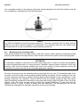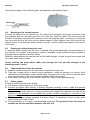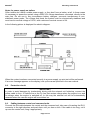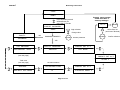
1
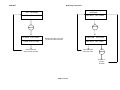
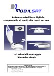
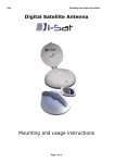
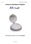
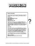
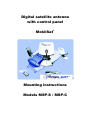
Digital satellite antenna
with control panel
MobilSat+
Mounting instructions
Models MSP-S / MSP-C
SUMMARY
1.
2.
Introduction...............................................................................................................................................2
Safety instructions.....................................................................................................................................3
2.1. Proper use (for the intended purpose).................................................................................................3
2.2. Safety during installation work...........................................................................................................3
2.3. Proper installation and safety..............................................................................................................3
2.4. Adhesive sealant .................................................................................................................................4
2.5. Road Traffic Licensing Regulations ...................................................................................................4
3. Certifications .............................................................................................................................................4
4. Package contents .......................................................................................................................................4
5. Unpacking and preparation .....................................................................................................................5
6. Mounting instructions ..............................................................................................................................5
6.1. Selection of the mounting position .....................................................................................................5
6.2. External unit space requirements ........................................................................................................5
6.3. Mounting of the assembly plate..........................................................................................................6
6.4. Mounting of the external system.........................................................................................................7
6.5. Passing the cables through the roof ....................................................................................................7
6.6. Cable installation inside the caravan...................................................................................................7
6.7. Power supply.......................................................................................................................................7
6.8. Protection circuit.................................................................................................................................8
6.9. Cabling between control and command units.....................................................................................8
6.10.
Connection to the satellite receiver.................................................................................................9
6.11.
Installation menu.............................................................................................................................9
7. Technical data .........................................................................................................................................12
8. Notes .........................................................................................................................................................12
9. References ................................................................................................................................................12
1. Introduction
Read carefully and completely this manual at least once before starting with mounting operations.
ATTENTION
The antenna and the control panel must be
mounted only by qualified personnel
In order to prevent danger during mounting operations, during normal operation and during vehicle
moving, please observe carefully the information provided in this manual.
The correct execution of the mounting operations and a correct cabling of the system are
fundamental prerequisites to guarantee conformity with related regulations.
The system is covered by CE brand and by a conformity declaration, as reported in Capter 3.
MobilSat
+
Mounting instructions
2. Safety instructions
2.1. Proper use (for the intended purpose)
The MobiSat+ is designed to receive digital TV and radio programs via satellite. The turntable can
be used to receive digital TV and radio signals in the frequency range from 10.70 to 12.75GHz.
Any use other than that specified above will void the warranty or guarantee.
The following circumstances result in the loss of all warranty and liability claims towards the
manufacturer:
• Improper installation
• Use of non-specified mounting materials, which cannot guarantee the mechanical reliability of
the antenna system
• Non-permissible use, e.g. use of the planar antenna for storage
• Structural changes or interference with the components and mounting accessories in the set,
which could endanger both the mechanical and functional reliability
• Improper or forcible opening of the components
• Use of cleaners containing solvents, such as acetone, nitro-cellulose combination thinners,
petrol etc.
• Failure to observe installation and safety instructions in this manual
The turntable may be operated in an ambient temperature range of -10 °C to +40 °C.
Operating the system outside this range may result in malfunctions or damage to the
system.
2.2.
Safety during installation work
When carrying out installation work in locations where there is a risk of falling, take
appropriate safety precautions, e.g. use of a working platform. Make sure that the vehicle
roof is sufficiently strong and stable to carry out the installation work (risk of damage or
collapsing of roof).
Make sure that:
• The turntable and connected units are disconnected from the power supply
• The person carrying out the installation or repair does not suffer from vertigo and can move
around safely on the roof of the caravan or motor home
• The person carrying out the repairs is wearing sturdy and non-slip shoes
• The person carrying out the installation or repair has a secure position to stand and hold on
while working
• The roof and the climbing equipment used (e.g. ladder) are dry, clean and non-slip
• The roof can withstand the weight of the person carrying out the repairs
• Nobody should be inside the caravan/motor home underneath the antenna during
dismantling/installation
2.3. Proper installation and safety
A crucial safety factor is proper performance of installation and electrical connection work, and the
specified alignment of the turntable in the direction of travel (park position), see also installation
and connection. Follow as precisely as possible the installation conditions and steps described.
Page 3 of 12
MobilSat
+
Mounting instructions
Modifications to the electrical installations in the vehicle should only be carried out by a specialist in
vehicle electrics. Do not make any unauthorized changes to the turntable.
2.4.
Adhesive sealant
The turntable is attached to the roof of the vehicle by adhesive and is secured by additional fixing
screws. Note that the curing of the adhesive sealant is temperature-dependent. It reaches its full
strength only after approximately five days.
2.5. Road Traffic Licensing Regulations
The applicable regulations must be observed in respect of fixed installation of the turntable on a
vehicle which is driven on public highways.
In particular, §§ 19/2; 30 C; 32 (2) and the EC directive 74/483 EEC are applicable. Briefly, they
state that no endorsement of the vehicle documentation is required unless the antenna unit causes
the height of the laden vehicle to exceed 2mt, or the antenna unit projects beyond the outer lateral
outline of the vehicle. The maximum permissible height of 4mt (vehicle and antenna unit) may not
be exceeded.
3. Certifications
MobilSat+ complies with the following regulations:
Electromagnetic compatibility:
Safety:
IP graduation:
Vibrations:
EN55022, EN55024
EN12100-1, EN12100-2, EN294, EN349
EN60529
95/56/CEE
4. Package contents
The received package contains the following items:
- Control Unit
- External unit with antenna dish
- Command unit
- Mounting plate
- Power cable
- Cable set (4mt) for external unit
- Cable (5mt) for command unit
- Coaxial cable (1,5m) for satellite receiver
- Mounting instructions
- User’s manual
- C.I. satellite receiver (with kit MSP-C)
Page 4 of 12
MobilSat
+
Mounting instructions
5. Unpacking and preparation
Please keep original packaging material because it will be needed in case of system return for
repair or maintenance actions. In other cases the supplier will not be responsible for damages
occurred during transport.
Please keep packaging materials out of reach of children.
6. Mounting instructions
6.1. Selection of the mounting position
After all doubts concerning roof stability have been eliminated and after all necessary measures
have been taken on order to assure a proper and safe assembly, position the external unit and the
antenna in the planned mounting position.
Once positioned, both antenna and LNB must be oriented towards the rear of the caravan,
opposite to driving direction. All other positions are considered not correct (see figure)
For the final choice of the mounting position, be absolutely sure of antenna space requirements
during normal operations.
Driving
direction
Rear of the
vehicle
6.2. External unit space requirements
Be sure that there is enough space for the folded up system and for the complete rotation of the
antenna. The space requirements for a correct mounting of the external unit are displayed in the
following figure:
Page 5 of 12
MobilSat
+
Mounting instructions
For a complete rotation of the antenna during the normal operation the roof of the vehicle must be
free of obstacles, as displayed in the following figure.
NOTE
For difficult installations caused by space problems, it must be underlined that the plate and the
LNB arm turns at a minimum height of 25 centimeters. Any obstacles present in the rotation area
but lower than 25 cm will not influence normal antenna operations.
6.3. Mounting of the assembly plate
After having decided the mounting location and after having verified antenna positioning during
stand-by time related to driving direction, mark on the roof the corner points of the mounting plate.
ATTENTION
It’s absolutely needed to mark the roof of the vehicle with a line, in order to exclude the possibility
to mount the assembly plate in a wrong direction. MobilSat+ antenna can be mounted in only one
direction; LNB must be oriented towards the rear of the vehicle. All other positions will not be
considered as correct and will cause immediate guarantee expiration.
Remove the system from the assembly plate unscrewing the four nuts. The assembly plate must
be glued to the roof using a commercially available sealing compound. For the cleaning of the roof
and the assembly plate use a special cleaning agent recommended by the manufacturer of the
sealing compound (e.g. SikaFlex, Teroson 1K-Pur). After the sealing compound has been dried,
apply the sealing compound to the bottom of the plate and strongly apply the plate to the roof of the
vehicle. If the roof of the caravan does not have the needed consistency, fix the plate with the
tapping screws, in order to obtain a stable and safe assembly. The manufacturer can not be
indicated as responsible for damages caused by an incorrect mounting.
Page 6 of 12
MobilSat
+
Mounting instructions
Seal also the edges of the assembly plate, as displayed in the following figure.
6.4. Mounting of the external system
Connect the cable set to the external unit. The cable can be plugged in the proper connector using
the dedicated space in the lower part of the unit. After this, insert the cable in the small recess on
the base of the plate and mount the external unit on the assembly plate, centering it on prisoners
and fixing with the four M8 nuts and the related washers. When finished cover the nuts with the
related covers. If the plate has been mounted correctly, now the LNB points exactly to the rear of
the vehicle.
6.5. Passing the cables through the roof
To pass the cables through the roof use, if available, the system adopted by the manufacturer of
the caravan. If no default manufacturers’ system is available, install a cable through (available in
package) with a diameter of at least 25mm.
Block the cable between the external unit and the cable through, in order to avoid movements that
can cause cable wear or break.
Check carefully the point where cable pass through the roof and the strength of the
blocking screws, if used.
6.6. Cable installation inside the caravan
a) Lead the cables coming from the external unit toward the control unit
b) Take care to cable fixing, in order to avoid oscillations - when the caravan is in motion. Such
oscillations could damage or broke internal wires; along the route to the control unit fix the cable
to the caravan walls using a commercially available cable fixing system.
c) If the cable is too long, coil it up near the control unit, fixing it in an appropriate way.
6.7. Power supply
Provide a sufficient power to the system.
a) The system must powered by a 12V power supply
b) Connect the power cable directly to battery terminals, avoiding to use a cable that powers
another utility. Often the cable section is not sufficient, to supply the original device (e.g. the
television set) plus the new one. In these conditions the voltage that feeds the unit could not be
sufficient. If this procedure is not applied the system could be damaged or not work in the
appropriate way.
c) The supply cable must have a section of at least 2.5mm2. For distances of 6mt or more, cable
section must be at least 4.0mm2
d) The ideal solution is to install a new dedicated power line. The protection fuse that must be
installed on this line should be between 10A and 15A.
Page 7 of 12
MobilSat
+
Mounting instructions
Notes for power supply on trailers
Often trailers don’t have a stable power supply, or they don’t have a battery at all. In these cases
it’s necessary to power the system using a 220V/12V voltage transformer connected, directly to the
main line. Do not use in any circumstance battery chargers, economic transformers or nonstabilized power packs. The voltage that feeds the system must be electronically stabilized and
must have a nominal voltage of 13.8V, with a minimum nominal current of 6A.
In the following picture is displayed the electric diagram.
When the system has been connected correctly to a power supply, an auto test will be performed.
If an error message appears on the display, look up the cause specified in the user manual.
6.8.
Protection circuit
IMPORTANT
In order to avoid damages by inadvertently driving with the external unit folded-up, connect the
yellow cable to the +15 vehicle line or the D+ line that carries voltage when the engine is on and
no-voltage when the engine is switched off. In this way the external unit will be automatically
retracted when the caravan engine will be switched on.
6.9. Cabling between control and command units
Connect the 5mt cable between the control and the command unit; take care of inserting the RJ11
connector in the right direction and push them until you here a click. If the cable is too long, coil it
up near the control unit, fixing it appropriately.
Page 8 of 12
MobilSat
+
Mounting instructions
6.10. Connection to the satellite receiver
Now it’s possible to connect the antenna system to the satellite receiver, using the F-connector
cable.
6.11. Installation menu
All the functions of the system are activated using the control panel, showed in the following
picture.
To activate operator menu press simultaneously the UP/DOWN keys for at least 3 seconds.
The system is password protected. To input password press UP/DOWN keys to modify the
selected digit and LEFT/RIGHT keys to change the selected digit. The default password is 3105.
After having inserted the right password it’s possible to activate all the installation functions.
In the following pages are showed all the functions and menus needed for installation.
Page 9 of 12
MobilSat
+
Mounting instructions
USER
MENU
In every menu, except
“Mech. Zero Set” e
”Factory settings”:
Keys UP/DOWN pressed
simultaneously for
more than 3 seconds
Menu’ XX
OK menu
INSERT PASSWORD
Digit selection
XXXX
Select from list
(scroll menù blocked)
Change value
FAULTY
NO
PASSWORD CORRECT?
PASSWORD
OK menu
OK menu
Confirm password
Confirm selection
YES
SET ANTENNA
SELECT LANGUAGE
PREDEF SAT N.1
MECHANICAL ZERO
ENGLISH
HOT BIRD
Mechanical reset
(see next page)
PREDEF SAT N.2
ASTRA 1
Total reset
(see next page)
RESTORE
DEFAULT SETTINGS
Set max elevation
ELEVATION TRIM
+2o
PREDEF SAT N.3
ATLANTIC BIRD 3
Page 10 of 12
MobilSat
+
Mounting instructions
RESTORE
SET ANTENNA
DEFAULT SETTINGS
MECHANICAL ZERO
OK menu
OK menu
SEARCH FOR MECH
ZERO EXECUTION
MOTORS ACTIVATED UNTIL END
OF ROTATION AND ELEVATION
CONFIRM
DEFAULT SETTING?
NO ACTIONS FOR
MORE THAN 5 SEC.
END OF ROTATION
AND ELEVATION REACHED
RESTORE
OK menu
RETURN TO
FACTORY
SETTINGS
Page 11 of 12
MobilSat
+
Mounting instructions
7. Technical data
Power supply:...………………………………..…. 11/16V
Current consumption stand-by mode:………….. 60mA
Current consumption during sat search:……..... 2A typ - 3,5A peak
Typical time for sat search:……………………….30-60 sec
Max time for sat search:……….…. …………….. 300 sec
External unit weight:……………………………….15,5Kg
8. Notes
____________________________________________________________________________________________
____________________________________________________________________________________________
____________________________________________________________________________________________
____________________________________________________________________________________________
____________________________________________________________________________________________
____________________________________________________________________________________________
____________________________________________________________________________________________
____________________________________________________________________________________________
____________________________________________________________________________________________
____________________________________________________________________________________________
9. References
Mobiltech s.a.s.
Via Brughetti, 9/E
20030 Bovisio Masciago (MI) - Italy
Tel: (+39) 0362 – 544.928
Fax: (+39) 0362 – 576.478
Internet: www.mobiltech.it
Mailto: [email protected]
Page 12 of 12