1
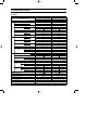
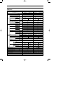
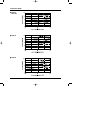
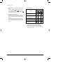
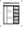
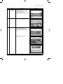
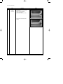
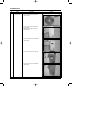
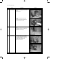
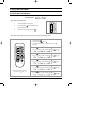
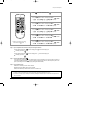
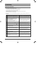
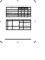
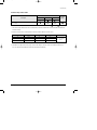
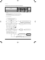
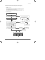
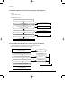
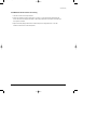
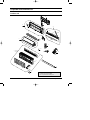
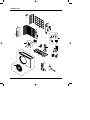
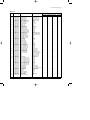
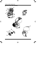
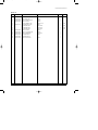
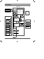
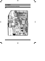
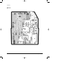
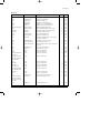
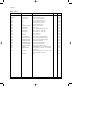
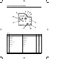
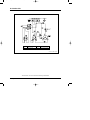
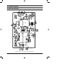
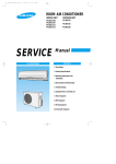
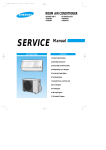
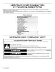
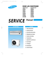
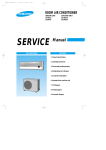
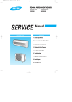
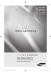
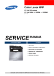
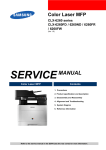
DB98_15920A(2)_co
04/3/9 10:34 AM
Page 3
ROOM AIR CONDITIONER
INDOOR UNIT
OUTDOOR UNIT
SH07AS2
SH07AS2A
SH09AS2
SH12AS4
SH07AS2X
SH07AS2AX
SH09AS2X
SH12AS4X
SERVICE
AIR CONDITIONER
Manual
CONTENTS
11. Product Specifications
12. Operating Instructions
13. Disassembly and Reassembly
14. Refrigerating Cycle Diagram
15. Set Up the Model Option
16. Troubleshooting
17. Exploded Views and Parts List
18. Block Diagram
19. PCB Diagram
10. Wiring Diagram
11. Schematic Diagram
DB98_15920A(2)_1
04/3/9 10:58 AM
Page 1
1. Product Specifications
1-1 Table
Model
Item
SH07AS2
Indoor unit
Type
Cooling
Outdoor unit
2.30
2.30
2.40
2.40
0.9
0.9
|/h
Cooling
Air Volume
m3/min
Heating
Noise
dB
Energy Efficiency Ratio
6.2
19
6.2
6.8
19
6.8
19
36
50
36
50
Cooling
Heating
2.95
W/W
3.24
1-220 / 240-50
780
780
Heating
740
740
Cooling
3.5
3.5
3.3
3.3
96.9
96.9
97.5
97.5
A
17.0
17.0
m
-
-
-
-
250V-10 / 16A
250V-10 / 16A
Cooling
W
A
Heating
Power
Cooling
Power Factor
%
Heating
Starting Current
Length
Power Cord
Number of Core Wire
Capacity
Outer
Dimension
WxHxD
Weight
Refrigerant Pipe
Size
A
mm
795 x 258 x 179
660 x 495 x 235
795 x 258 x 179
660 x 495 x 235
inch
31.3 x 10.2 x 7.0
26.0 x 19.5 x 9.3
31.3 x 10.2 x 7.0
26.0 x 19.5 x 9.3
kg
7.5
25.6
7.5
25.6
Liquid
mm x L(m)
ø6.35 x 7.5
ø6.35 x 7.5
GAS
mm x L(m)
ø9.52 x 7.5
ø9.52 x 7.5
D x L(mm)
ø18 x 2,000
ø18 x 2,000
Drain Hose
Type
Compressor
Motor
Rotary
Motor
Rotary
Type
-
-
-
-
Rated Output
-
-
-
-
Cross-flow
Propeller
Cross-flow
Propeller
steel
steel
steel
steel
11
20
11
20
1ROW 22STEP
2ROW 10STEP
Type
Blower
2.95
3.24
V-Hz
Operating Current
19
1-220 / 240-50
Power
Power Consumption
Outdoor unit
Wall-mounted
Heating
Performance
Indoor unit
Wall-mounted
kW
Dehumidifying
SH07AS2A
Type
Rated Output
W
Heat Exchanger
2ROW 10STEP
Refrigerant Control Unit
Freezer Oil Capacity
cc
Refrigerant to Change(R410A)
g
1ROW 22STEP
CAPILLARY TUBE
CAPILLARY TUBE
350
350
600
600
Protection Device(OLP)
MRA99901-9201
RAC12126-9622
Cooling Test Condition
INDOOR UNIT : DB27˚C WB19˚C
OUTDOOR UNIT : DB35˚C WB24˚C
Maximum Operation Condition
INDOOR UNIT : DB32˚C WB23˚C
OUTDOOR UNIT : DB43˚C WB26˚C
Samsung Electronics
1
DB98_15920A(2)_1
04/3/9 10:58 AM
Page 2
Table(cont.)
Model
Item
SH09AS2
Indoor unit
Type
Cooling
Outdoor unit
2.70
3.50
2.90
3.80
1.4
1.9
|/h
Cooling
Air Volume
m3/min
Heating
Noise
dB
Energy Efficiency Ratio
6.8
19
8.2
7.4
19
8.8
24
39
51
43
53
Cooling
Heating
2.87
W/W
3.22
1-220 / 240-50
940
1,240
Heating
900
1,180
Cooling
4.2
5.4
4.0
5.2
97.3
99.8
97.8
98.7
A
21.0
32.0
m
-
-
-
-
250V-10 / 16A
250V-10 / 16A
Cooling
W
A
Heating
Power
Cooling
Power Factor
%
Heating
Starting Current
Length
Power Cord
Number of Core Wire
Capacity
Outer
Dimension
WxHxD
Weight
Refrigerant Pipe
Size
A
mm
795 x 258 x 179
660 x 495 x 235
890 x 285 x 179
720 x 530 x 260
inch
31.3 x 10.2 x 7.0
26.0 x 19.5 x 9.3
35.0 x 11.2 x 7.0
28.3 x 20.9 x 10.2
kg
7.5
26.3
8.5
33.0
Liquid
mm x L(m)
ø6.35 x 7.5
ø6.35 x 7.5
GAS
mm x L(m)
ø9.52 x 7.5
ø12.7 x 7.5
D x L(mm)
ø18 x 2,000
ø18 x 2,000
Drain Hose
Type
Compressor
Motor
Rotary
Motor
-
-
-
-
Rated Output
-
-
-
-
Cross-flow
Propeller
Cross-flow
Propeller
steel
steel
steel
steel
11
20
15
25
1ROW 22STEP
2ROW 12STEP
Type
Rated Output
W
Heat Exchanger
2ROW 10STEP
Refrigerant Control Unit
2
Rotary
Type
Type
Blower
2.82
3.22
V-Hz
Operating Current
24
1-220 / 240-50
Power
Power Consumption
Outdoor unit
Wall-mounted
Heating
Performance
Indoor unit
Wall-mounted
kW
Dehumidifying
SH12AS4
Freezer Oil Capacity
cc
Refrigerant to Change(R410A)
g
1ROW 24STEP
CAPILLARY TUBE
CAPILLARY TUBE
280
500
500
750
Protection Device(OLP)
RBC12131-12500
RBC12128-12500
Cooling Test Condition
INDOOR UNIT : DB27˚C WB19˚C
OUTDOOR UNIT : DB35˚C WB24˚C
Maximum Operation Condition
INDOOR UNIT : DB32˚C WB23˚C
OUTDOOR UNIT : DB43˚C WB26˚C
Samsung Electronics
DB98_15920A(2)_1
04/3/9 10:58 AM
Page 3
1-2 Pressure Graph
■ SH07AS2
■ SH07AS2A
■ SH09AS2
■ SH12AS4
Samsung Electronics
3
DB98_15920A(2)_1
04/3/9 10:59 AM
Page 4
2. Operating Instructions
2-1 The Feature of Key in remote control
No
NAMED OF KEY
FUNCTION OF KEY
On/Off & Timer Set/Cancel button.
Press the
button to stop and run the air conditioner or On/Off timer set up.
1
Mode selection button.
Each time you press this button,
Mode is changed in the following order.
2
: Auto Mode
: Fan Only
: Cool Mode
: Heat Mode
: Dry Mode
(UP)
Temperature adjustment button(UP).
To increase the temperature by the pressing the temperature button.
(DOWN)
Temperature adjustment button(DOWN).
To decrease the temperature by the pressing the temperature button.
3
Turbo/Sleep mode selection button.
Press the
button one or more times until
appears. The air conditioner cools or
heats the room as quickly as possible. After 30minutes, the air conditioner is reset automatically
to the previous mode.
4
Turbo/Sleep mode selection button.
Press the
button one or more times until
appears. The sleep timer can be used
when you are cooling or heating your room to switch the air conditioner off
automatically after a period of six hours.
5
4
Fan speed adjustment button.
Each time you press this button,
FAN SPEED is changed in the following order.
6
Swing button.
It adjusts the airflow to upward and downward.
7
On Timer button.
The On Timer enables you to switch on the air conditioner automatically
after a given period of time that is from 30 minutes to 24 hours.
To cancel, press the
(Set/Cancel) button.
8
Off Timer button.
The Off Timer enables you to switch off the air conditioner automatically
after a given period of time that is from 30 minutes to 24 hours.
To cancel, press the
(Set/Cancel) button.
9
Energy Saving button.
If you wish to save energy when using your air conditioner, select the Energy saving mode
with the
button.
Samsung Electronics
DB98_15920A(2)_1
04/3/9 10:59 AM
Page 5
Operating Instructions
2-1-1 Name & Function of Key in remote control
1.
AUTO MODE : In this mode, operation mode(COOL,
HEAT) is selected automatically by the room temperature
of initial operation.
DRY MODE : Has 3 states, each determined by room
temperature.
The unit operates in DRY mode.
*Compressor ON/OFF Time is controlled compulsorily
(can not set up the fan speed, always breeze).
*Protective function : Low temperature release.
(Prevention against freeze)
5.
TURBO MODE : This mode is available in AUTO, COOL,
HEAT, DRY, FAN MODE.
When this button is pressed at first, the air conditioner is
operated ''powerful'' state for 30 minutes regardless of the
set temperature, room temperature.
When this button is pressed again, or when the operating
time is 30 minutes, turbo operation mode is canceled and
returned to the previous mode.
*But, if you press the TURBO button in DRY or FAN
mode that is changed with AUTO mode automatically.
6.
SLEEP MODE : Sleep mode is available only in COOL or
HEAT mode.
The operation will stop after 6 hours.
*In COOL mode : The setting temperature is automatically raised by 1°C each 1hour When the temperature has
been raised by total of 2°C, that temperature is maintained.
*In HEAT mode : The setting temperature is automatically
dropped by 1°C each 1hour.
When the temperature has been dropped by total of 2°C,
that temperature is maintained.
7.
FAN SPEED : Manual (3 step), Auto (4 step)
Fan speed automatically varies depending on both the
difference between setting and the room temperature.
8.
COMPULSORY OPERATION :
For operating the air conditioner without the remote
control.
*The air conditioner starts up in the most suitable mode
for the room temperature:
Operation Type
Room Temp
Tr≥ 21°C+∆T
Cool Operation (Set Temp:24˚C+∆T)
21°C +∆T>Tr
Heat Operation (Set Temp:22˚C+∆T)
∆T= -1°C, -2°C, 0°C, +1°C, +2°C
∆T is controlled by setting temperature up/down key of
remote control
2.
COOL MODE : The unit operates according to the
difference between the setting and room temperature.
(18°C~30°C)
3.
HEAT MODE : The unit operates according to the
difference between the setting and room temperature.
(16°C~30°C)
*Prevention against cold wind : In order to prevent the
cool air from flowing out at the heat mode, the indoor fan
does not operate or operates very slowly in the
following cases. At this time, the indoor heat exchanger
will be preheating.
- For 3~5 minutes after the initial operation
- For deicing operation
- The operation of an indoor fan in accordance with the
temperature of an indoor heat exchanger
The temperature of
indoor heat exchanger
Indoor fan speed
below 28˚C
off
28˚C~below 34˚C
LL Speed
34˚C~below 40˚C
L Speed
above 40˚C
Setting Speed
*High temperature release function : It is a function to
detect an outdoor overload by the sensor of an indoor
heat exchanger and to turn the outdoor fan or the
compressor ON/OFF for safety.
*Deice : Deicing operation is controlled by indoor unit's
heat exchanger temperature and accumulating time of
compressor's operation.
Deice ends by sensing of the processing time by deice
condition.
Samsung Electronics
4.
Room Temperature
Operating Mode
Temperature Setting
Less than 21˚C
Heat
22˚C approx.
21˚C or above
Cool
24˚C approx.
5
DB98_15920A(2)_1
04/3/9 10:59 AM
Page 6
Operating Instructions
9.
SWING : BLADE-H is rotated vertically by the stepping
motor.
*Swing Set : Press the
button under the remote
control is displayed on LCD the
and the blades
move up and down. If the one more time press the
button, blades location is stop.
10. SETTING THE ON/OFF TIMER. :
*ON TIMER : The On Timer enables you to switch on
the air conditioner automatically after a given period of
time. You can set the period of time from 30 minutes to
24 hours.
*OFF TIMER : The Off Timer enables you to switch off
the air conditioner automatically after a given period of
time. You can set the period of time from 30 minutes to
24 hours.
11. SELF DIAGNOSIS
LAMP or DISPLAY Monitor
Description
OPERATION
TIMER
TURBO
Indoor unit room temperature sensor
error(open or short)
Indoor unit heat exchanger
temperature sensor error(open or short)
Indoor fan motor malfunction
EEPROM error
Option error(option wasn’t set up or
option data error)
: Lamp off
: Lamp flickering
12. BUZZER SOUND : Whenever the On/Off button is
pressed or whenever change occurs to the condition
which is set up or select, the compulsory operation mode,
buzzer is sounded "beep".
6
Samsung Electronics
DB98_15920A(2)_1
04/3/9 10:59 AM
Page 7
2-2 Replace PCB Model option
2-2-1 Replace PCB model option
Remove power cord
Replace the PCB module
Check the connection and plug in
No
Does all display lamp blink?
Replace another PCB
Yes
Refer to set up the Model option(14~16page)
Samsung Electronics
7
DB98_15920A(2)_1
04/3/9 11:24 AM
Page 8
3. Disassembly and Reassembly
Stop operation of the air conditioner and remove the power cord before repairing the unit.
3-1 Indoor Unit
No
Parts
1
Front Panel
Procedure
Remark
1) Stop the air conditioner operation and
block the main power.
2) Detach tape of the Front Panel upper.
3) Open the upper Front Grille by pulling
right and left sides of the Grille.
4) Slide the lower Front Grille down, then
disassemble it by pulling it forwards.
5) Take the left and right Filter out.
6) Loosen one of the right screw and
separate the Terminal Cover.
7) Detach the thermistor from the Front Grille.
8) Loosen 5 fixing screws of Front Grille.
9) At first, press the left and center hook of
the back side of the Panel Grille with the
thumb to remove the hook. And press the
right of the upper side of the Panel Grille
with the fingers. And then disassemble the
Panel Grille.
10) Pull the lower left and right of discharge
softly for the outside cover to be pulled
out.
8
Samsung Electronics
DB98_15920A(2)_1
04/3/9 11:24 AM
Page 9
Disassembly and Reassembly
No
Parts
2
Electrical Parts
(Main PCB)
3
Tray Drain
4
Heat Exchanger
Procedure
Remark
1) Take all the connector of PCB upper side
out.(Including Power Cord)
2) Detach the outdoor unit connection wire
from the Terminal Block.
3) If pulling the main PCB up, it will be taken
out.
1) Pull Tray Drain out from the Back Body.
1)
2)
3)
4)
Loosen 2 fixing earth screws of right side.
Detach the Connection Pipe.
Detach the Holder Pipe at the rear side.
Loosen 3 fixing screws of right and left
side.
5) Detach the Heat Exchanger from the
indoor unit.
Samsung Electronics
9
DB98_15920A(2)_1
04/3/9 11:24 AM
Page 10
Disassembly and Reassembly
No
Parts
5
Fan Motor
&
Cross Fan
Procedure
Remark
1) Loosen 2 fixing screws and detach the
Motor Holder.
2) Loosen 1 screw of Fan Motor.
(By use of M3 wrench)
3) Detach the Fan Motor from the Fan.
4) Detach the Fan from the left Holder
Bearing.
10
Samsung Electronics
DB98_15920A(2)_1
04/3/9 11:24 AM
Page 11
3-2 Outdoor Unit
No
Parts
1
Common Work
Procedure
Remark
1) Loosen 1 fixing screw and detach the
Cover Terminal.
2) Loosen 1 fixing screw and detach the
Cover Control.
3) Detach the connection wire from the
Terminal Block.
4) Loosen 13 fixing screws and detach the
Cabinet-Front.
5) Loosen 1 fixing screw of Ass'y E-part.
6) Loosen 4 fixing screws and detach the
Cabinet-Side.
Samsung Electronics
11
DB98_15920A(2)_1
04/3/9 11:24 AM
Page 12
Disassembly and Reassembly
No
Parts
2
Fan and Motor
Procedure
Remark
1) Detach the Nut Flange (Turn to the clockwise).
2) Detach the Fan.
3) Loosen 4 fixing screws to detach the
Motor.
4) Loosen 5 fixing screws and detach the
Motor Bracket from the Base.
12
3
Heat Exchanger
1) Loosen 2 fixing screws of left and right
side.
2) Disassemble the inlet and outlet pipe by
welding.
3) Detach the Heat Exchanger.
4
Compressor
1) Open the Terminal Cover of Compressor
and unscrew the Connection Terminal.
2) Disassemble the inlet and outlet pipe of
Compressor by welding.
3) Loosen 3 bolts of the lower part.
4) Detach the Compressor.
Samsung Electronics
DB98_15920A(2)_1
04/3/9 10:59 AM
Page 13
4. Refrigerating Cycle Diagram
Outdoor Unit
Indoor Unit
Capillary tube
T1
2-Way valve
Heat
Exchanger
(Evaporator)
Heat
Exchanger
(Evaporator)
Propeller Fan
Cross Fan
Liquid side
T2
Gas side
3-Way valve
4-Way valve
Cooling
Compressor
Heating
Gas leak check point
Samsung Electronics
13
DB98_15920A(2)_1
04/3/9 11:00 AM
Page 14
5. Set Up the Model Option
5-1 Setting Option Setup Method
ex) Option No. :
Step 1 : Enter the Option Setup mode.
1st
Take out the batteries of remote control.
2nd
Press the temperature
insert the battery again.
3rd
Make sure the remocon display shown as
button simultaneously and
.
Step 2 : Enter the Option Setup mode and select your option according to the following procedure.
1
The default value is
Otherwise, push the
.
button to
.
Every time you push the button, the display panel reads
or
repeatedly.
1
2
2
Push the
3
Every time you push the button, the display panel reads
...
repeatedly.
4
button to set the display panel to
.
3
Push the
button to set the display panel to
.
Every time you push the button, the display panel reads
...
repeatedly.
5
6
4
Push the
button to set the display panel to
.
Every time you push the button, the display panel reads
...
repeatedly.
5
Push the
button to set the display panel to
.
Every time you push the button, the display panel reads
...
repeatedly.
✳ Setting is not required if you must
a value which has a
default.
6
Push the
button to set the display panel to
.
Every time you push the button, the display panel reads
...
repeatedly.
14
Samsung Electronics
DB98_15920A(2)_1
04/3/9 11:01 AM
Page 15
Set Up the Model Option
7
Press
button, then the default value is
.
8
Push the
7
button to set the display panel to
.
Every time you push the button, the display panel reads
...
repeatedly.
8
9
9
10
Push the
button to set the display panel to
.
Every time you push the button, the display panel reads
...
repeatedly.
11
10
12
Push the
button to set the display panel to
.
Every time you push the button, the display panel reads
...
repeatedly.
11
Push the
button to set the display panel to
.
Every time you push the button, the display panel reads
...
repeatedly.
12
✳ Setting is not required if you must
a value which has a
default.
Push the
button to set the display panel to
.
Every time you push the button, the display panel reads
...
repeatedly.
Step 3 : Upon completion of the selection, check you made right selections.
Press the Mode Selection key,
to set the display part to and check the display part.
The display part shows
.
Press the Mode Selection key,
The display part shows
to set the display part to
and check the display part.
.
Step 4 : Pressing the ON/OFF button (
)
When pressing the operation ON/OFF key with the direction of remote controller for unit, the sound ''Ding'' or ''Diriring'' is
heard and the OPERATION ICON( ) lamp of the display is flickering at the same time, then the input of option is completed. (If the diriring sound isn't heard, try again pressing the ON/OFF button.)
Step 5 : Unit operation test-run
First, Remove the battery from the remote controller.
Second, Re-insert the battery into the remote controller.
Third, Press ON/OFF key with the direction of remote controller for set.
• Error Mode
1st If all lamps of indoor unit are flickering, Plug out and plug in battery again and pressing ON/OFF key to retry.
2nd If the unit is not working properly or all lamps are continuously flickering after setting the option code, see if the correct option code is
set up for it's model.
Samsung Electronics
15
DB98_15920A(2)_1
04/3/9 11:01 AM
Page 16
Set Up the Model Option
■ OPTION ITEMS
REMOCON
SEG1
SEG2
SEG3
SEG4
SEG5
SEG6
SEG7
SEG8
SEG9 SEG10 SEG11 SEG12
SH07AS2
0
2
6
0
6
5
1
7
A
0
F
b
SH07AS2A
0
2
6
0
6
5
1
7
A
0
F
b
SH09AS2
0
2
6
0
6
5
1
7
A
2
2
E
SH12AS4
0
6
8
0
2
4
1
7
A
3
5
1
MODEL
16
Samsung Electronics
DB98_15920A(2)_1
04/3/9 11:01 AM
Page 17
6. Troubleshooting
6-1 Items to be checked first
1.
The input voltage should be rating voltage ±10% range.
The airconditioner may not operate properly if the voltage is out of this range.
2.
Is the link cable linking the indoor unit and the outdoor unit linked properly?
The indoor unit and the outdoor unit shall be linked by 5 cables.
Check the terminals if the indoor unit and outdoor unit are properly linked by the same number of cables.
Otherwise the airconditioner may not operate properly.
3.
When a problem occurs due to the contents illustrated in the table below it is a symptom not related to the malfunction of the
airconditioner.
No
Operation of air conditioner
Explanation
1
The OPERATION indication LED(GREEN) blinks when a
power plug of the indoor unit is plugged in for the first time.
It indicates power is on. The LED stops blinking if the operation ON/OFF button on the remote control unit is pushed.
2
In a COOL operation mode, the compressor does not
operate at a room temperature higher than the setting
temperature that the INDOOR FAN should operate.
[In case of heat pump model]
In a HEAT operation mode, the compressor does not
operate at a room temperature lower than the setting
temperature that indoor fan should operate.
In happens after a delay of 3 minutes when the compressor
is reoperated. The same phenomenon occurs when a power
is on.
As a phenomenon that the compressor is reoperated after a
delay of 3 minutes, the indoor fan is adjusted automatically
with reference to a temperature of the air blew.
3
Fan speed setting is not allowed in DRY(
The speed of the indoor fan is set to LL in DRY mode.
Fan speed is selected automatically in AUTO mode.
4
Compressor stops operation intermittently in DRY(
mode.
5
Timer LED(GREEN) of the indoor unit lights up and the
air conditioner does not operate.
Timer is being activated and the unit is in ready mode.
The unit operates normally if the timer operation is cancelled.
6
The compressor stops intermittently in a COOL mode or
DRY mode, and fan speed of the indoor unit decreases.
The compressor stops intermittently or the fan speed of the
indoor unit decreases to prevent inside/outside air frozen
depending on the inside/outside air temperature.
7
[In case of heat pump model]
Compressor of the outdoor unit is operating although it is
turned off in a HEAT mode.
When the unit is turned off while de-ice is activated,
the compressor continues operation for up to 9 minutes
(maximum) until the deice is completed.
8
[In case of heat pump model]
The compressor and indoor fan stop intermittently in
HEAT mode.
The compressor and indoor fan stop intermittently if room
temperature exceeds a setting temperature in order to protect
the compressor from overheated air in a HEAT mode.
9
[In case of heat pump model]
Indoor fan and outdoor fan stop operation intermittently
in a HEAT mode.
The compressor operates in a reverse cycle to remove
exterior ice in a HEAT mode, and indoor fan and outdoor fan
do not operate intermittently for within 20% of the total heater
operation
Samsung Electronics
) mode.
)
Compressor operation is controlled automatically in DRY
mode depending on the room temperature and humidity.
17
DB98_15920A(2)_1
04/3/9 11:01 AM
Page 18
Troubleshooting
4.
Indoor unit observes operation condition of the air conditioner, and displays self diagnosis details on the display panel.
LAMP
OPERATION
Error Mode
TIMER
7-segment
Display
TURBO
Indoor unit room temperature sensor error
(open or short)
Indoor unit heat exchanger temperature sensor error
(open or short)
Indoor fan motor malfunction
EEPROM error
Option error
(option wasn't set up or option data error)
Display
Flickering
: Lamp off
5.
Operation with abnormal motion
No
1
2
18
: Lamp flickering
Abnormal condition
No response from
the remote control
operation signal.
Unable to operate the
outdoor unit
Inspection
• Plug out and plug in 5 seconds
later.
• Press the TURBO button with the
remote control.
• In 3 minutes, check the voltage
between the indoor unit terminal
block N(1) and 1.
Initial Diagnosis
Able to operate the
remote control.
OK
Unable to operate
the remote control.
Press the
(ON/OFF) button in the
indoor unit.
• If it operates, the remote control and
indoor unit receiver are in trouble.
• If not, the indoor unit is in trouble.
AC198V ~ AC242V
Problem with the outdoor unit or PCB
No power source
displayed.
Problem with the relay (RY71) or PCB
Samsung Electronics
DB98_15920A(2)_1
04/3/9 11:01 AM
Page 19
6-2 Fault Diagnosis by Symptom
6-2-1 No Power (completely dead)-Initial diagnosis
1. Checklist :
1) Is input voltage normal?
2) Is AC power linked correctly?
3) Is input voltage of DC regulator IC KA7805 (IC02) normal? (11VDC-12.5VDC)
4) Is output voltage of DC regulator IC KA7805 (IC02) normal? (4.5VDC-5.5VDC)
2. Troubleshooting procedure
Unplug the power cord and
plug it after 5 seconds
Press the Power Button on the
remote control unit to
operate the air conditioner
operate
◆ Check the display board
does not operate
◆ Check the indoor unit
control board
Check whether two wires
of power cord are
connected correctly to the
terminal block and control board.
No
Reconnect wires correctly
Yes
Check whether the fuse on the
control board is normal.
FUSE: 3.15[A]/250[V]
No
Replace fuse
Yes
Check the output of SMPS
on the control board.
Input power: AC230±15%[V]
IC02 Input: DC 12[V]
IC02 output: DC 5[V]
No
PCB should be replaced
Yes
◆ Check the setting temperature
Samsung Electronics
19
DB98_15920A(2)_1
04/3/9 11:01 AM
Page 20
Troubleshooting
6-2-2 Room temperature sensor failure
LAMP
OPERATION
Description
TIMER
TURBO
7-segment
Display
: Lamp off
: Lamp flickering
Indoor unit room temperature sensor error(open or short)
Detach the assembly sensor from the
ASS'Y PCB CN43 connector and measure
the sensor resistance with an ohmmeter (tester).
Is the sensor resistance value
10KΩ ±3% at the room temperature
of 25˚C?
No
ASS'Y Sensor Replace
SENSOR Resistance Value : 20˚C-12.09kΩ
SENSOR Resistance Value : 30˚C-8.31kΩ
SENSOR Resistance Value : 35˚C-6.94kΩ
SENSOR Resistance Value : 40˚C-5.83kΩ
Yes
Connect the sensor to CN43,
supply power, and measure the voltage of
#1 and #2 of the CN43 connector.
Below 0.5V?
Yes
Poor ASS'Y PCB Replace
No
Yes
Over 4.9V?
Poor ASS'Y PCB Replace
No
MICOM Error or Connector(CN43) check
20
Samsung Electronics
DB98_15920A(2)_1
04/3/9 11:01 AM
Page 21
Troubleshooting
6-2-3 Room Pipe sensor failure
LAMP
OPERATION
Description
TURBO
7-segment
Display
: Lamp off
: Lamp flickering
TIMER
Indoor unit heat exchanger temperature sensor error
(open or short)
1. Check the assembly condition of the sensor connector(CN43) on the indoor unit Main PCB and if not assembled, reassemble the
connector accurately.
2. Detach the room pipe sensor connector(CN43) and check the resistance between connector 3 and 4.
Temperature(˚C)
Resistance Value(Kohm)
Temperature(˚C)
Resistance Value(Kohm)
15
14.68
30
8.31
20
12.09
35
6.94
25
10
40
5.83
Others
The data tolerance
is ±3%.
If the above data is not met, replace the room pipe sensor.
3. Assemble the room pipe sensor to PCB, plug in, and check the voltage of connector 3 and 4. If the resistance is below 0.5V or
over 4.9V, replace the indoor Main PCB. (short or disconnected in the PCB board)
Samsung Electronics
21
DB98_15920A(2)_1
04/3/9 11:01 AM
Page 22
Troubleshooting
6-2-4 When the Indoor Unit Fan Does Not Operate. (Initial Diagnosis)
LAMP
OPERATION
Description
TIMER
TURBO
7-segment
Display
: Lamp off
: Lamp flickering
Indoor fan motor malfunction
1. Checklist :
1) Is the indoor unit fan motor properly connected with the connector (CN72)?
2) Is the AC voltage correct?
3) Is HALL IC in indoor fan motor properly connected with the connector (CN44)?
4) Is the running capacitor (CR71) properly connected with PCB board?
2. Troubleshooting procedure
After unplugging out the power cord should
be reconnected within 5 seconds.
Yes
No
Check as in the procedure "NO power"
Does the OPERATION lamp blink?
Yes
Does the Solid State Relay(SS71) work properly?
Test rod location
+
-
SS71-
SS71-
No
Micom is
out of order.
Micom should be replaced
Normal
Voltage
12V
Yes
No
Is the supply voltage of the fan motor sufficient?
Test rod location
PCB CN72
Condition
pin #3 and #5
Fan operating
PCB is
out of order.
PCB should be replaced.
Normal
voltage
About AC 180V
Motor Fan-Capacitor is out of order
Yes
Fan motor is out of order.
22
Replace Motor
Fan-Capacitor
Fan motor should be replaced.
Samsung Electronics
DB98_15920A(2)_1
04/3/9 11:01 AM
Page 23
Troubleshooting
6-2-5 When the Outdoor Unit Does Not Operate. (Initial Diagnosis)
1. Checklist :
1) Is input voltage normal?
2) Is the set temperature of the remote control higher than room temperature in COOL mode?
3) Is the set temperature of the remote control lower than room temperature in HEAT mode?
4) Is the POWER IN connector (CN71) linked correctly?
5) Is the outdoor unit properly connected with the TERMINAL BLOCK connector(N(1), 1, 2, 3)?
2. Troubleshooting procedure
After unplugging out the power cord should be
reconnected within 5 seconds.
No
Does the OPERATION lamp blink
Check as in the procedure "No Power"
Yes
Yes
Does the timer lamp blink during operation ?
Room temperature sensor is
out of order
!
No
#
+
-
Condition
Normal
Voltage
IC4 Pin No.38
GND
RY71 ON
DC 4.8V
Micom is
out of order.
No
Is the power relay RY71 operated by adjusting the
room temperature?
Test rod location
Sensor Should be
replaced
@
PCB should be
checked.
No
Power relay is
out of order
Is rating voltage ±10% range applied relay between
Terminal block No. N(1) and No. 1
Yes
Power relay should be
replaced.
Outdoor unit is
out of order.
!
Yes
No
@
Is the room sensor normal resistor?
10°C
20°C
30°C
17.96kΩ
12.09kΩ
8.3kΩ
Yes
#
Samsung Electronics
23
DB98_15920A(2)_1
04/3/9 11:01 AM
Page 24
Troubleshooting
6-2-6 When the UP/DOWN Louver Motor Does Not Operate. (Initial Diagnosis)
1. Checklist :
1) Is input voltage normal?
2) Is the UP/DOWN louver motor properly connected with the connector (CN61)?
2. Troubleshooting procedure
Remove power cord and plug in again in approx. 5 seconds.
No
Is STD lamp blinking?
Check as in the procedure
"No Power".
Yes
Yes
Does operation start when swing button of the
remote control unit pushed?
Normal
No
Voltage at pin #57~#60 of micom (IC04) change?(Squarewave)
No
Micom (IC04) is faulty.
Yes
No
Voltage at pin #2 ~ #5 of CN61(motor connector)
change?(Squarewave)
Driver IC06/08 (ULN2003A) is faulty.
Yes
UP/DOWN louver motor is faulty.
6-2-7 In the HEAT mode, When there is no warm air current. Check this fist;
1. Is the set temperature of Remote Control lower than room temperature in Heat mode?
2. Is the Indoor PCB properly connected with the CN71 connector?
After training on, the heating operation
should start in 5 minutes.
Yes
Normal
No
Is the number #38 of Micom (IC04) DC 5.0V?
No
Abnormal Micom
Yes
Is the number checking #11 of IC05 (ULN2003A) LOW?
No
Abnormal IC05
Yes
Is the voltage between CN71 #1 and CN71 #5 rating voltage ±10% range
No
Abnormal RY73
Yes
Abnormal 4-Way valve of Outdoor Unit.
or connecting Cable
PCB should be replaced.
4-Way valve should be replaced
or connecting Cable Check.
24
Samsung Electronics
DB98_15920A(2)_1
04/3/9 11:01 AM
Page 25
Troubleshooting
6-2-8 When the remote control is not receiving
1. Check if the connector was normally assembled.
2. Put the set in operation and check the voltage of No. 3(+) and No. 2(-) of the main PCB CN91 while operating the
remote control. When the voltage descends below 3V, the assembly module PCB is normal and the main PCB is poor.
Then replace the main PCB.
3. Replace the assembly display PCB because the module PCB is poor if the voltage between No. 2~3 of CN91
maintains 5V after the remote control starts operation.
Samsung Electronics
25
DB98_15920A(2)_1
04/3/9 11:01 AM
Page 26
7. Exploded Views and Parts List
7-1 Indoor Unit
11
13
6
14
6-2
14-1
6-1
7
14-6
14-2
14-4
3
14-3
8
9
14-5
3-1
5
10
1
12
15
1-2
1-1
1-3
1-6
1-5
1-4
2
1-7
4
You can search for the updated part code
number through the ITSELF.
URL : http://itself.sec.samsung.co.kr
26
Samsung Electronics
DB98_15920A(2)_1
04/3/9 11:01 AM
Page 27
Exploded Views and Parts List
■
Parts List
Q'TY
No.
Code No.
1
DB92-00574A
DB92-00582A
DB92-00575A
DB92-00581A
DB64-00984A
DB64-00987A
DB63-00858A
DB63-00856A
DB63-00859A
DB63-00857A
DB64-00986A
DB61-01630A
DB61-01629A
DB64-00985A
DB64-00988A
DB96-03109A
DB96-02145G
DB96-03102A
DB96-03101A
DB63-00581A
DB63-00588A
DB93-01364B
DB94-00490A
DB94-00508A
DB61-01779A
DB61-01119A
DB94-00258A
DB94-00040R
DB94-00040F
DB31-00152B
DB31-00152A
DB61-01099A
DB61-01120A
DB67-60030A
DB70-00276A
DB70-00288A
DB93-02539A
DB93-02524A
DB90-00992A
DB61-01121A
DB94-00468B
DB94-00465A
DB63-00587A
DB63-00592A
DB94-00062E
DB61-01103A
DB61-01125A
DB61-01104A
DB61-01126A
DB95-20138A
DB63-00634A
DB63-00635A
DB93-01549B
1-1
1-2
1-3
1-4
1-5
1-6
1-7
2
3
3-1
4
5
6
6-1
6-2
7
8
9
10
11
12
13
14
14-1
14-2
14-3
14-4
14-5
14-6
15
Samsung Electronics
Description
ASS'Y PANEL FRONT TOTAL
ASS'Y PANEL FRONT TOTAL
ASS'Y PANEL FRONT SVC
ASS'Y PANEL FRONT SVC
GRILLE UP
GRILLE UP
FILTER-AIR LF
FILTER-AIR LF
FILTER-AIR RH
FILTER-AIR RH
WINDOW DISPLAY
HOLDER PCB
HOLDER DISPLAY
GRILLE LOW
GRILLE LOW
ASS'Y EVAPORATOR TOTAL
ASS'Y EVAPORATOR TOTAL
ASS'Y EVAPORATOR
ASS'Y EVAPORATOR
COVER TERMINAL
COVER TERMINAL
ASS'Y REMOCON
ASS'Y BACK BODY
ASS'Y BACK BODY
BACK BODY
BACK BODY
ASS'Y BEARING
ASS'Y CROSS FAN
ASS'Y CROSS FAN
MOTOR-FAN IN
MOTOR-FAN IN
HOLDER-MOTOR
HOLDER-MOTOR
SPRING-SENSOR
PLATE-HANGER
PLATE-HANGER
ASS'Y CONTROL IN
ASS'Y CONTROL IN
HOLDER-PIPE
HOLDER-PIPE
ASS'Y TRAY DRAIN
ASS'Y TRAY DRAIN
TRAY DRAIN
TRAY DRAIN
ASS'Y HOSE DRAIN
BLADE-H
BLADE-H
BLADE-V
BLADE-V
ASS'Y STEPPING MOTOR
GUARD-SAFETY WIRE
GUARD-SAFETY WIRE
ASS'Y CONNECTOR POWER
Specification
ASS'Y
ASS'Y
ASS'Y
ASS'Y
ABS
ABS
PP
PP
PP
PP
PC
HIPS
ABS
ASS'Y
ASS'Y
ASS'Y
ASS'Y
ASS'Y
ASS'Y
HIPS
HIPS
ASS'Y
ASS'Y
ASS'Y
HIPS
HIPS
ASS'Y
ASS'Y
ASS'Y
PP
PP
STS301
SGCC-M
SGCC-M
ASS'Y
ASS'Y
HIPS
HIPS
ASS'Y
ASS'Y
HIPS
HIPS
ASS'Y
HIPS
HIPS
PP
PP
ASS'Y
STS27
STS27
1mm2x3C
SH07AS2
SH07AS2A
SH09AS2
SH12AS4
1
1
1
1
1
1
1
1
1
1
1
1
1
1
1
1
1
1
1
1
1
1
1
1
1
1
1
3
1
1
1
1
1
1
1
1
1
1
1
1
1
1
1
1
1
1
1
1
1
1
1
1
1
1
1
1
1
1
3
1
1
1
1
1
1
1
1
1
1
1
1
1
1
1
1
1
1
1
1
1
1
1
1
1
1
1
1
1
1
3
1
1
1
Remark
OPTION
OPTION
27
DB98_15920A(2)_1
04/3/9 11:01 AM
Page 28
7-2 Outdoor Unit
5
23
14
13
7
6
15-1 15-2
12
15
15-4
2
15-7
15-3
3
9
10
4
15-6
1
22
21
15-5
20
4-1
18
19
8
11
16
17
4-2
28
Samsung Electronics
DB98_15920A(2)_1
04/3/9 11:01 AM
Page 29
Exploded Views and Parts List
■
Parts List
No.
Code No.
Description
Q'TY
Specification
SH07AS2X SH07AS2AX SH09AS2X
1
2
3
4
4-1
4-2
5
6
7
8
9
10
11
12
13
14
15
15-1
15-2
15-3
15-4
15-5
15-6
15-7
16
17
18
19
20
21
22
23
DB60-30020A
DB67-00036A
DB67-50063A
DB31-00034A
DB31-10058C
DB90-01405A
DB90-01406A
DB64-00978A
DB64-00999A
DB63-00863A
DB63-00862A
DB64-00979A
DB64-01001A
DB64-00980A
DB90-01426A
DB63-10443C
DB90-01404A
DB90-01273B
DB90-01273A
DB61-01623A
DB61-01648A
DB94-00561C
DB73-00067A
DB73-00070A
DB63-00930A
DB96-02976A
DB96-02985A
DB96-02984A
DB64-00998A
DB64-00997A
DB94-00497B
DB94-00497A
DB94-00520A
DB93-02556C
DB93-02556B
DB93-02556A
DB93-02556Q
2501-001237
2501-001236
2301-001375
DB65-40049E
DB93-01547D
DB93-01547C
DB35-00028B
DB35-00028C
DB35-00026A
DB35-00015T
DB67-60020A
DB33-00049B
DB96-03142A
DB96-03144A
DB96-03145A
DB96-03532A
DB96-03143A
DB96-03146A
DB96-03146B
DB96-03146D
G8C124JU1EL
G4A097JU1EP
DB95-00477A
G4A080JV1EP
DB60-30028A
DB63-20002A
DB63-00929A
DB63-10165D
DB63-00927A
DB60-30018A
DB60-30020A
DB64-01003A
Samsung Electronics
NUT FLANGE
FAN PROPELLER
FAN PROPELLER
MOTOR FAN OUT
MOTOR FAN OUT
ASS'Y CABINET FRONT
ASS'Y CABINET FRONT
CABINET FRONT
CABINET FRONT
GUARD FAN
GUARD FAN
CABINET SIDE LF
CABINET SIDE LF
CABINET SIDE RH
CABINET SIDE RH
COVER E PARTS ASS'Y
ASS'Y BASE OUTDOOR
ASS'Y BASE OUTDOOR
ASS'Y BASE OUTDOOR
BRACKET VALVE
BRACKET MOTOR
BRACKET MOTOR
GROMMET-ISOLATOR
GROMMET-ISOLATOR
GROMMET-ISOLATOR
ASS'Y COND
ASS'Y COND
ASS'Y COND
SCREEN COND
SCREEN COND
ASS'Y PARTITION
ASS'Y PARTITION
ASS'Y PARTITION
ASS'Y CONTROL OUT
ASS'Y CONTROL OUT
ASS'Y CONTROL OUT
ASS'Y CONTROL OUT
CAPACITOR-COMP
CAPACITOR-COMP
CAPACITOR-MOTOR
TERMINAL BLOCK
ASS'Y LEAD WIRE
ASS'Y LEAD WIRE
OLP
OLP
OLP
OLP
OLP SPRING
ASS'Y SOLENOID COIL
ASS'Y TUBE 4WAY VALVE
ASS'Y TUBE 4WAY VALVE
ASS'Y TUBE 4WAY VALVE
ASS'Y TUBE 4WAY VALVE
ASS'Y TUBE CAPILLARY
ASS'Y TUBE CAPILLARY
ASS'Y TUBE CAPILLARY
ASS'Y TUBE CAPILLARY
COMPRESSOR
COMPRESSOR
COMPRESSOR
COMPRESSOR
NUT WASHER
GASKET
GASKET
COVER TERMINAL
COVER TERMINAL
NUT FLANGE
NUT FLANGE
HANDLE CABINET LF
2C,M6,SM20C,NTR
AS+G/F 20%,ø375
AS+G/F 20%,ø405
220/240V,50/60Hz
220/240V,50/60Hz
ASS'Y
ASS'Y
SECC-P
SECC-P
PP
PP
SECC-P
SECC-P
SECC-P
SECC-P
ASS'Y
ASS'Y
ASS'Y
ASS'Y
GALVANIZED STEEL
GALVANIZED STEEL
GALVANIZED STEEL
NR
NR
NR
ASS'Y
ASS'Y
ASS'Y
PP
PP
ASS'Y
ASS'Y
ASS'Y
ASS'Y
ASS'Y
ASS'Y
ASS'Y
35uF/450VAC
30uF/450VAC
1.5uF/450VAC
4P
SAMSUNG COMPor
MATSUSHITA COMPor
RBC 12128-12500
RBC 12131-12500
MRA99901-9201
RAC12126-9622
STS304
ASS'Y
ASS'Y
ASS'Y
ASS'Y
ASS'Y
ASS'Y
ASS'Y
ASS'Y
ASS'Y
220-240V/50Hz
220-240V/50Hz
5PS102, 220-240V/50Hz
220-240V/50Hz
HEX 2C M8 ZPC
EPDM
EPT
POM
PET
M5, SM20C
M6
PP
1
1
1
1
1
1
1
1
1
1
1
1
3
1
1
1
1
1
1
1
1
1
1
1
1
1
1
3
1
1
1
1
1
1
1
1
1
1
1
1
1
1
1
1
3
1
1
1
1
1
1
1
1
1
1
1
1
1
1
3
1
1
1
1
1
1
1
1
1
1
1
1
1
1
1
1
3
1
1
1
1
1
1
1
1
1
1
1
1
1
1
3
1
1
1
1
SH12AS4X
1
1
1
1
1
1
1
1
1
1
1
1
3
1
1
1
1
1
1
1
1
1
1
1
1
1
1
3
1
1
1
1
29
DB98_15920A(2)_1
04/3/9 11:02 AM
Page 30
7-3 Ass'y Control In (Indoor Unit)
■ SH07AS2/SH07AS2A/SH09AS2 : DB93-02524A
30
Samsung Electronics
DB98_15920A(2)_1
04/3/9 11:02 AM
Page 31
Exploded Views and Parts List
■
Parts List
No.
Code No.
Description
Specification
Q'TY
Remark
1
DB61-01127A
CASE-CONTROL
ABS
1
2
DB93-02447A
ASS'Y-MAIN PCB
ASS'Y
1
3
DB93-02508A
ASS'Y-TERMINAL BLOCK
ASS'Y
1
4
DB93-02525A
ASS'Y SUB PCB
ASS'Y
1
5
DB70-00289A
PLATE-TERMINAL LOW
SGCC-M T1.2
1
6
DB61-00171A
HOLDER-WIRE CLAMP
ABS
1
7
-
SCREW-MACHINE
PH M3xL22
1
SNA
8
-
SCREW-MACHINE
TH M4xL16
2
SNA
SNA
9
-
SCREW-MACHINE
PH M4xL10
1
10
DB39-00949A
ASS'Y C/W SUB
ASS'Y
1
11
DB39-00643M
ASS'Y C/W STEP MOTOR
ASS'Y
1
12
DB32-00020A
ASS'Y-THERMISTOR
4P(103AT)
1
13
DB61-01629A
HOLDER DISPLAY
ABS
1
14
DB64-00986A
WINDOW DISPLAY
-
1
15
DB61-01630A
ASS'Y HOLDER PCB
HIPS
1
Samsung Electronics
31
DB98_15920A(2)_1
04/3/9 11:02 AM
Page 32
Exploded Views and Parts List
■ SH12AS4 : DB93-02539A
32
Samsung Electronics
DB98_15920A(2)_1
04/3/9 11:02 AM
Page 33
Exploded Views and Parts List
■
Parts List
No.
Code No.
Description
Specification
Q'TY
1
DB61-01631A
CASE-CONTROL
ABS
1
2
DB93-02447A
ASS'Y-MAIN PCB
ASS'Y
1
3
DB93-02508A
ASS'Y-TERMINAL BLOCK
ASS'Y
1
4
DB93-02525A
ASS'Y SUB PCB
ASS'Y
1
5
-
PLATE-TERMINAL LOW
SGCC-M T1.2
1
6
DB61-00171A
HOLDER-WIRE CLAMP
ABS
1
7
-
SCREW-MACHINE
PH M3xL22
1
SNA
8
-
SCREW-MACHINE
TH M4xL16
2
SNA
9
-
SCREW-MACHINE
PH M4xL10
1
SNA
10
DB39-00949A
ASS'Y C/W SUB
ASS'Y
1
11
DB39-00643F
ASS'Y C/W STEP MOTOR
ASS'Y
1
12
DB32-00020A
ASS'Y-THERMISTOR
4P(103AT)
1
13
DB61-01629A
HOLDER DISPLAY
ABS
1
14
DB64-00986A
WINDOW DISPLAY
-
1
15
DB61-01630A
ASS'Y HOLDER PCB
HIPS
1
Samsung Electronics
Remark
SNA
33
DB98_15920A(2)_1
04/3/9 11:02 AM
Page 34
8. Block Diagram
* : Option
CONTROLLER
IC-MCU
HEAT EXCHANGER SENSOR
• BLADE CONTROL
• AUTO GRILLE CONTROL*
ROOM TEMPERATURE SENSOR
• INDOOR FAN MOTOR CONTROL
• COMPRESSOR CONTROL
INFRARED SIGNAL
• TEMPERATURE CONTROL
• TIMER
RESET
CIRCUIT
DISPLAY PART
TURBO
OPERATION
• BUZZER CONTROL
TIMER
• FUNCTION CONTROL*
TEMPERATURE*
FUNCTION
OSCILLATION
CIRCUIT
ZERO
VOLTAGE
DETECT
REMOTE CONTROLLER
• COMPRESSOR CONTROL
SIGNAL
POWER ON/OFF
TRIGGER
SIGNAL
• STEPPING MOTOR
CONTROL SIGNAL
• BUZZER CONTROL SIGNAL
MODE
(AUTO, COOL, DRY,
FAN)
TURBO OPERATION
FAN SPEED SELECT
(H/M/L)
• FUNCTION CONTROL SIGNAL*
INDOOR FAN MOTOR
(left/right)
SSR
AC INPUT
• COMPRESSOR DRIVE
• OUTDOOR FAN MOTOR
DRIVE
• STEPPING MOTOR DRIVE
COMPRESSOR
OUTDOOR FAN MOTOR
BUZZER
FUNCTION
PART
• BUZZER DRIVE
BLADE-H
MOVING SELECT
• FUNCTION DRIVE*
STEPPING MOTOR
-Blade
-Auto grille*
ON, OFF TIMER
SELECT
TEMPERATURE
SELECT
DC 5V
VOLTAGE REGULATOR
SLEEP SELECT
DC 12V
SMPS Power Block
FUNCTION*
SELECT
AC INPUT
34
Samsung Electronics
DB98_15920A(2)_1
04/3/9 11:02 AM
Page 35
9. PCB Diagram
9-1 ASS'Y MAIN PCB(7K/9K/12K) : DB93-02447A
■ TOP
Samsung Electronics
35
DB98_15920A(2)_1
04/3/9 11:02 AM
Page 36
PCB Diagram
■ BOTTOM
36
Samsung Electronics
DB98_15920A(2)_1
04/3/9 11:02 AM
Page 37
PCB Diagram
■
Parts List
Location No.
Description
Specification
Q'TY
Remark
D71
DIODE-RECTIFIER
UF4007,1KV,1A,DO-41,TP
1
SNA
D102
DIODE-RECTIFIER
UG2D,200V,2A,DO-204AC,TP
1
SNA
BD71
DIODE-BRIDGE
DF06S,600V,1A,SMD-4,TP
1
SNA
D101
DIODE-ZENER
BZX84C3V6,3.6,350mW,SOT-23,TP
1
SNA
D103
DIODE-ZENER
BZX84-C11,10.4-11.6V,350mW,SOT-23,TP
1
SNA
CD01
DIODE-TVS
ST02D-200,185/200/215V,200W,DO-214
1
SNA
Q201,Q401,Q601,Q603
TR-SMALL SIGNAL
2SC2412K,NPN,200mW,SOT-23,TP,1
4
SNA
Q602
TR-SMALL SIGNAL
MMST2907A,PNP,200mW,SOT-23,TP,100-300
1
SNA
Q901,Q902
TR-DIGITAL
DTA114EKA,PNP,200mW,10K/10K,SOT-23,TP
2
SNA
IC05,IC08
TR-ARRAY
2003,NPN,7,1W,SOP-16,ST,1000
2
SNA
PC01
PHOTO-COUPLER
TR,130-260%,200mW,DIP-4,ST
1
SNA
PC02
PHOTO-COUPLER
TR,50-150%,200mW,DIP-4,ST
1
SNA
IC51
IC-EEPROM
93LC56,128x16Bit,SOP,8P,150MIL,-,2.5V,-,PLASTIC
1
SNA
-40to+85CC,1uA,CMOS,TP
IC03
IC-VOLTAGE COMP.
7533,TO-92,3P,-,SINGLE,-,-,PLASTIC
1
SNA
IC02
IC-POSI.ADJUST REG.
78L05A,TO-92,3P,-,PLASTIC,4.6
1
SNA
IC01
IC-PWM CONTROLLER
255,DIP,8P,300MIL,PLASTIC,-0.3/700V,-,-40TO+150C
1
SNA
NTC1
THERMISTOR-NTC
22Ohm,1.4A,3100K,9.5mW/C,-,7.0
1
SNA
VA71
VARISTOR
560V,2500A,17.5x7.5mm,TP
1
SNA
R609
R-CHIP
560ohm,5%,1/8W,TP,2012
1
SNA
R102
R-CHIP
100ohm,5%,1/8W,TP,2012
1
SNA
R209,R501,R601,R603
R-CHIP
10Kohm,5%,1/8W,TP,2012
6
SNA
R-CHIP
1Kohm,5%,1/8W,TP,2012
11
SNA
R103
R-CHIP
220ohm,5%,1/8W,TP,2012
1
SNA
R405,R406
R-CHIP
330ohm,5%,1/8W,TP,2012
2
SNA
530mA,-,ST
R605,R908
R210,R211,R212,R301
R302,R401,R402,R404
R602,R604,R610
R606,R909
R-CHIP
4.7Kohm,5%,1/8W,TP,2012
2
SNA
R101,R607,R608
R-CHIP
470ohm,5%,1/8W,TP,2012
3
SNA
R201,R202,R203,R204
R-CHIP
47Kohm,5%,1/4W,TP,3216
8
SNA
R407,R408
R-CHIP
6.8Kohm,1%,1/8W,TP,2012
2
SNA
R403
R-CHIP
6.8Kohm,5%,1/8W,TP,2012
1
SNA
C107
C-CERAMIC,DISC
2.2nF,20%,400V,Y5U,BK,12.5x6mm,10
1
SNA
C103,C105,C106,C201
C-CER,CHIP
100nF,+80-20%,50V,Y5V,TP,2012
14
SNA
C-CER,CHIP
1nF,10%,50V,X7R,TP,2012
1
SNA
R205,R206,R207,R208
C204,C301,C302,C402
C403,C501,C502,C503
C504,C901
C401
Samsung Electronics
37
DB98_15920A(2)_1
04/3/9 11:02 AM
Page 38
PCB Diagram
■
Parts List(cont.)
Location No.
Description
Specification
Q'TY
Remark
C202,C203,C404
C-CER,CHIP
10nF,+80-20%,50V,Y5V,TP,2012
3
SNA
XC72,XC71
C-FILM,LEAD-PPF
100nF,10%,275V,BK,18x6x12,15
2
SNA
CR71
C-FILM,LEAD-PPF
1.2uF,10%,450Vac,BK,38x18x30,3
1
SNA
C102
C-AL
470uF,20%,25V,GP,TP,10x12.5mm
1
SNA
C101
C-AL
10uF,20%,450V,GP,TP,13x20mm,5m
1
SNA
C104
C-AL
470uF,20%,16V,GP,TP,10x12.5,5
1
SNA
C601
C-AL
47uF,20%,50V,GP,TP,6.3x11,5
1
SNA
X501
RESONATOR-CERAMIC
10MHz,0.5%,BK,8x3x5.5mm
1
SNA
BZ61
BUZZER-PIEZO
85DB,-,-,2KHz,-
1
SNA
RY71
RELAY-POWER
12VDC,0.9W,20000mA,SPST,20mS,10mS
1
SNA
RY72
RELAY-POWER
DC12V,3A 250V AC,-,-,10mS,10mS
1
SNA
RY73
RELAY-POWER
DC12V,3A 250V AC,-,-,10mS,10mS
1
SNA
SS71
SSR
12Vdc,-,2A,1mS,1mS
1
SNA
F702
FUSE-CLIP
250V,7.5A,30mohm
1
SNA
F702
FUSE-CARTRIDGE
250V,3.15A,TIME-LAG,GLASS,5x20mm
1
SNA
CN71
CONNECTOR-HEADER
1WALL,3P,1R,7.92mm,STRAIGHT,SN,BLU
1
SNA
CN72
CONNECTOR-HEADER
1WALL,3P,1R,7.92mm,STRAIGHT,SN,WHT
1
SNA
CN91
CONNECTOR-HEADER
BOX,8P,1R,2mm,ANGLE,SN
1
SNA
CN61
CONNECTOR-HEADER
BOX,5P,1R,2mm,ANGLE,SN,WHT
1
SNA
CN43
CONNECTOR-HEADER
BOX,4P,1R,2mm,STRAIGHT,SN
1
SNA
CN44
CONNECTOR-HEADER
BOX,3P,1R,2.5mm,ANGLE,TIN,BLU
1
SNA
IC04
IC MICOM
S3C848AXZZ-QTRA,-,64P,+5V,10MHz,STM-0219-EA
1
SNA
ST11
TRANS SWITCHING
EI1916-048,SS-P/J,-,200V~240V,-,-,EI1916,50/60Hz,-
1
SNA
FT71
COIL CHOKE
1
SNA
1
SNA
1.6mH(1P-3P),-,-,-,-,USAV-07153,UU1116,15.0mH,-25˚C~+85˚C,-,1.3ohm,15mH,105,20x18mm,13,0.6,BK,-25˚C
-
38
PCB BOARD
FR-4
Samsung Electronics
DB98_15920A(2)_1
04/3/9 11:02 AM
Page 39
9-2 ASS'Y SUB PCB(7K/9K/12K) : DB93-02525A
■
Parts List
No.
Description
Specification
Q'TY
Remark
1
PCB-DISPLAY
FR-1
1
SNA
2
TACT SWITCH
YTP-1280A
1
SNA
3
CONNECTOR
SMSW200-08(WHT)
1
SNA
4
LED-LAMP
GRN(SM3517)
2
SNA
5
LED-LAMP
ORG(SO3517)
1
SNA
6
RESISTOR
470ohm,1/2W
1
SNA
7
MODULE REMOCON
FRP4021H10
1
SNA
8
DIODE
1N4148
1
SNA
9
C-CERAMIC
1nF/50V
1
SNA
10
C-CERAMIC
100nF/50V
1
SNA
11
JUMPER
10mm
1
SNA
Samsung Electronics
39
DB98_15920A(2)_1
04/3/9 11:02 AM
Page 40
10. Wiring Diagram
10-1 Indoor Unit(7K/9K/12K)
Code No : DB98-15135A
This Document can not be used without Samsung's authorization.
40
Samsung Electronics
DB98_15920A(2)_1
04/3/9 11:02 AM
Page 41
10-2 Outdoor Unit
C1
MOTOR CAPACITOR
C2
COMP CAPACITOR
FM
O.L.P
FAN MOTOR
OVER LOAD PROTECTOR
Code No : DB98-15123A
This Document can not be used without Samsung's authorization.
Samsung Electronics
41
DB98_15920A(2)_1
04/3/9 11:02 AM
Page 42
11. Schematic Diagram
11-1 Indoor Unit(7K/9K/12K)
This Document can not be used without Samsung's authorization.
42
Samsung Electronics
DB98_15920A(2)_1
04/3/9 11:02 AM
Page 43
MEMO
Samsung Electronics
43
DB98_15920A(2)_1
04/3/9 11:02 AM
Page 44
MEMO
44
Samsung Electronics
DB98_15920A(2)_co
04/3/9 10:34 AM
Page 2
ELECTRONICS
This Service Manual is a property of Samsung Electronics Co., Ltd.
Any unauthorized use of Manual can be punished under applicable
International and/or domestic law.
© Samsung Electronics Co., Ltd. Mar. 2004.
Printed in Korea.
Code No. DB98-15920A(2)