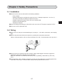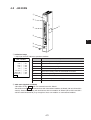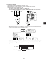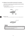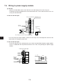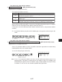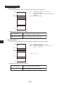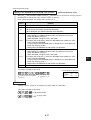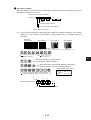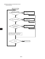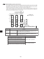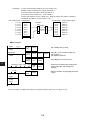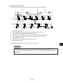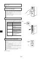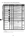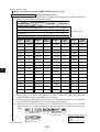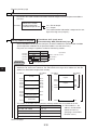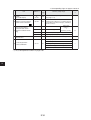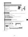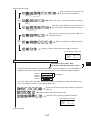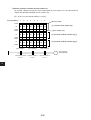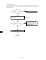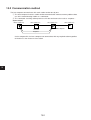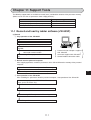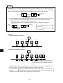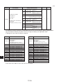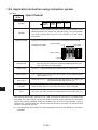
1
Version 2.2
Produced in Oct. 1997
R
SHARP Programmable Controller
New Satellite W series
Model Name
Network module
Remote I/O slave module
User’s Manual
JW-20CM
JW-20RS
Thank you for purchasing the network module (JW-20CM), remote I/O slave module (JW-20RS) for the
SHARP programmable controller.
Read this manual thoroughly to completely familiarize yourself with the operation according to the
examples.
Besides this manual, the manuals of control module, support tool, and option module are available for the
respective programmable controller.
We ask you to also read these manuals as well as this manual.
Keep this manual for future reference. We are confident that this manual will be helpful whenever you
encounter a problem.
Note
★ This manual describes the JW-20CM, JW-20RS with 30Hn mark in front of the module. The
following functions are added for the JW-20CM and JW-20RS without [30Hn] marks.
① This module can be communicated with JW30H.
② For data link, available for use the following functions.
· Data link (memory capacity save function)
· Data memory start system for SEND/RECEIVE function.
In this manual, additional functions are represented by the V5 mark.
★ In this manual, programmable controller is referred to as “PC.”
★ In this manual, programmable controllers and I/O modules with model name "ZW-xx" are
referred to as "ZW model," and programmable controllers and I/O modules with model name
"JW-xx" are referred to as "JW model."
Note
· This manual is written with the utmost care.
· No part of this manual may be reproduced in any form without permission of SHARP corporation.
· The contents of this manual are subject to change without prior notice.
Safety Precautions
Read this manual and attached documents carefully before installation, operation, maintenance and checking
in order to use the machine correctly. Understand all of the machine knowledge, safety information, and
cautions before starting to use. In this instruction manual, safety precautions are ranked into "danger" and
"caution" as follows.
Danger
: Wrong handling may possibly lead to death or heavy injury.
Caution
: Wrong handling may possibly lead to medium or light injury.
Even in the case of
Caution , a serious result may be experienced depending on the
circumstances. Anyway, important points are mentioned. Be sure to observe them strictly.
The picture signs of prohibit and compel are explained below.
: It means don’ts. For example, prohibition of disassembly is indicated as (
: It means a must. For example, obligation of grounding is indicated as (
1)
).
).
Installation
Caution
• Use in the environments specified in the catalog, instruction manual, and user's manual.
Electric shock, fire or malfunction may be caused when used in the environments of high
temperature, high humidity, dusty or corrosive atmosphere, vibration or impact.
• Install according to the manual.
Wrong installation may cause drop, breakdown, or malfunction.
• Never admit wire chips or foreign matters.
Or fire, breakdown or malfunction may be caused.
2)
Wiring
Compel
• Be sure to ground.
Unless grounded, electric shock or malfunction may be caused.
Caution
• Connect the rated power source.
Connection of a wrong power source may cause a fire.
• Wiring should be done by a qualified electrician.
Wrong wiring may lead to fire, breakdown or electric shock.
3)
Use
Danger
• Don’t touch the terminal while the power is being supplied or you may have an electric shock.
• Assemble the emergency stop circuit and interlock circuit outside of the programmable
controller. Otherwise breakdown or accident damage of the machine may be caused by the
trouble of the programmable controller.
Caution
• “RUN” or “STOP’” during operation should be done with particular care by confirming safety.
Misoperation may lead to damage or accident of the machine.
• Turn on the power source in the specified sequence. Turning ON with wrong sequence may
lead to machine breakdown or accident.
4)
Maintenance
Prohibit
• Don’t disassemble or modify the modules.
Or fire, breakdown or malfunction may be caused.
Caution
• Turn OFF the power source before detaching or attaching the module.
Or electric shock, malfunction or breakdown may be caused.
■ Configuration of this manual
The network module JW-20CM has three functions: "remote I/O," "data link," and "computer link" functions.
Accordingly, this manual describes about these three functions. Read each section according to your use of
any of these functions.
Users who use the network module for the first time.
Read this manual from chapter 1.
First, thoroughly understanding general, precautions, name and function of each section. Then, read
the contents from chapter 5 for proper use.
Users who want to use the remote I/O function.
Read from chapter 1 to chapter 7 and properly install and connect wiring work of the module. Then set
switches and parameters by referring chapter 8 for correct use.
Switch setting
· Master module: JW-20CM ....... See page 8·9
· Slave module: JW-20RS .......... See page 8·14
Parameter setting
· Master module: JW-20CM ....... See page 8·19
· Slave module: JW-20RS .......... See page 8·30
Users who want to use the data link function (including the computer link function)
Read from chapter 1 to chapter 7 and properly install and connect wiring work of the module. Then set
switches and parameters by referring chapter 9 for correct use.
The module also can function the computer link as data link system with a host computer having a
network module: ZW-98CM/ZW-20AX.
Switch setting
· Master module ............... See page 9·17
· Slave module ................. See page 9·17
Parameter setting
· Master module ............... See page 9·22
· Slave module ................. See page 9·33
Users who want to use only the computer link function
Read from chapter 1 to chapter 7 and properly install and connect wiring work of the module. Then set
switches by referring chapter 10 for correct use.
Switch setting ......... See page 10·3
Users who want to save and load parameter contents using a support tool.
Carefully read the contents of chapter 11 for correct use.
Users who want to add a communication station.
Carefully read the contents of chapter 7 and add a station.
Network module JW-20CM
Remote I/O slave module JW-20RS
- User’s Manual -
Chapter 1. Outline
Chapter 2. Safety Precautions
Chapter 3. System Configuration
Chapter 4. Name and Function of Each Part
Chapter 5. Installation
Chapter 6. Processing of Cables
Chapter 7. Wiring
Chapter 8. Remote I/O
Chapter 9. Data Link
Chapter 10. Computer Link
Chapter 11. Support Tools
Chapter 12. Specifications
Chapter 13. Appendix
Table of contents
Chapter 1 Outline ................................................................................................................................... 1·1
Chapter 2 Safety Precautions ............................................................................................................... 2·1
2-1 Installation 2·1
2-2 Wiring 2·1
2-3 Treatment 2·3
2-4 Static electricity 2·3
2-5 Maintenance 2·3
Chapter 3 System Configuration .......................................................................................................... 3·1
Chapter 4 Name and Function of Each Part ........................................................................................ 4·1
4-1 JW-20CM 4·1
4-2 JW-20RS 4·3
Chapter 5 Installation ............................................................................................................................. 5·1
5-1 JW-20CM 5·1
5-2 JW-20RS 5·4
Chapter 6 Processing of Cables ........................................................................................................... 6·1
6-1 Processing cable end 6·2
6-2 Connector crimping procedure 6·5
Chapter 7 Wiring .................................................................................................................................... 7·1
7-1 Cable trunk and branch lines 7·1
7-2 Relaying of trunk cables 7·1
7-3 Cable wiring procedure in control panel 7·2
7-4 Waterproof and insulation processing of connectors 7·4
7-5 Wiring of cables at outside control panels 7·5
7-6 Check after wiring 7·5
7-7 Wiring method for adding a communication station 7·6
7-8 Wiring to power supply module 7·8
Chapter 8 Remote I/O ............................................................................................................................. 8·1
8-1 Description of remote I/O 8·1
8-2 Data transfer required time and communication timing 8·3
8-3 Outline of switch and parameter setting procedure 8·8
8-4 Error and treatment 8·46
Chapter 9 Data Link ............................................................................................................................... 9·1
9-1 Description for data link function 9·1
9-2 Communication method 9·2
9-3 Data transfer required time and communication delay time 9·12
9-4 Expansion of network 9·15
9-5 Switch setting of master station or slave station 9·17
9-6 Setting contents of slave station parameters 9·22
9-7 Setting contents of master station parameters 9·33
9-8 Error and treatment 9·53
Chapter 10 Computer link ....................................................................................................................10·1
10-1 Description for computer link 10·1
10-2 Computer link function 10·2
10-3 Switch setting 10·3
10-4 Command 10·4
Chapter 11 Support Tools ..................................................................................................................... 11·1
11-1 Record and load by ladder software (JW-50SP) 11·1
11-2 Remote function 11·5
Chapter 12 Specifications ....................................................................................................................12·1
12-1 JW-20CM 12·1
12-2 JW-20RS 12·4
Chapter 13 Appendix ........................................................................................................................... 13·1
13-1 Maintenance and check 13·1
13-2 Switch setting table 13·2
13-3 Parameter memory table 13·3
13-4 Address map of data memory 13·20
13-5 Instructions used with the F200 and F201 link function 13·22
13-6 Application instruction using instruction system 13·26
Chapter 1 Outline
Using network module JW-20CM, you can construct a communications system (satellite net) which
can easily send and receive an ON/OFF signal (machine information) and numerical data (production
data) between PCs and a host computer using equipment control.
Using remote I/O slave module JW-20RS, you can construct a remote I/O system as master station for
PC that installed JW-20CM.
PCs which can use JW-20CM and JW-20RS are W70H/100H, JW50/70/100, and JW50H/70H/100H.
1
① Data link/computer link function
This function enables to send and receive ON/OFF signals and numeric data between modules on
a network (satellite net) which is connected PCs and personal computers having network module
ZW-20CM/JW-20CM/JW-22CM, network module ZW-98CM/ZW-20AX, and satellite net board Z335J.
② Remote I/O function
If remote I/O slave module ZW-20RS/JW-20RS are mounted on I/O modules located separately,
one PC having a network module JW-20CM can control these slave modules. (Connectable
maximum 63 modules of slave stations.)
· In the remote I/O function, the remote I/O can choose either of synchronous or asynchronous for
sending and receiving data with slave stations.
Synchronous type: Slave station scans input/output operation one time for each operation of
the PC.
Asynchronous type: When PC's operation time is longer than data transfer required time of the
remote I/O, the slave station scans input/output operation one time for each
operation of the PC. When PC's operation time is shorter than the data
transfer required time of the remote I/O, the slave station operate input and
output one time for several operation of the PC.
③ Remote programming/remote monitor function
By constructing a satellite system using the JW-20CM, you can program and monitor other station’s
PC’s (master station’s PC in case that remote I/O function) on the satellite system using a support
tool.
· These remote programming and remote monitor functions are also available beyond one
hierarchical layer difference (satellite net ←→ satellite net, satellite net ←→ SUMINET-3200).
* “SUMINET-3200” is a trademark of Sumitomo Electric Industries, Ltd.
1·1
Chapter 2 Safety Precautions
2-1 Installation
● Do not install or store the JW-20CM in the following conditions.
• Direct sunlight
• Ambient temperature exceeding the range of 0 to 55 ˚C (Storage temperature : -20 to 70 ˚C)
• The relative humidity exceeding the range of 35 to 90%.
• Sudden temperature changes which may cause condensation.
• Corrosive or inflammable gas
• Vibration or hard jolts
● Prior to installing or detaching the JW-20CM, make sure to turn OFF the power supply to the PCs.
● All screws must be tightened firmly.
2-2 Wiring
● Make sure to use only the recommended types (see page 6 · 1) for cables, connectors, and crimping
tools.
● When using connectors for branch or joint lines, provide jackets to protect connectors.
(When a connector touches with an external enclosure or the like, a communication error may occur.)
“T” jacket
(insulation cover)
“L” jacket
(insulation cover)
● Do not connect the ground terminal of the power supply module together with other equipment’s
ground lines. Make sure to provide class-3 grounding.
When the JW-20CM is used without connecting a class-3 grounding, malfunctions by noise may
occur.
● Communication cables should be arranged as far from any high voltage lines and strong power lines
as possible. Do not lay the communication cable parallel or proximate to these lines.
2·1
2
● Communication cables should be laid from the master station to the slave station one by one.
Multiple wiring from one point or wiring without terminators may cause communication errors.
Joint using a
connector
2
● Arrange total cable length within 1 km.
● Arrange branch cable line from a trunk within 400 mm.
● Prior to any electric welding around the JW-20CM, take out the coaxial cable from the JW-20CM.
While the coaxial cable is connected to the JW-20CM, any electric welding nearby the JW-20CM will
cause the welding current to enter the JW-20CM and may damage part of its circuit pattern.
JW-20CM
Coaxial cable
JW-20CM
JW-20CM has a
fuse element here
Wraparound current
Turn “ON”
shield ground
Turn “ON”
shield ground
FG
FG
Rack etc.
Note: In case enough
conductivity is not
established.
Electric welder
2·2
2-3 Treatment
● For ventilation, holes are provided in the cabinet to prevent a temperature rise. Do not block the
ventilation holes. Good ventilation is necessary.
● Never allow a liquid such as water and chemical solution and a metallic object like a copper wire
inside the JW-20CM to avoid a possible hazard. Otherwise, it may be a cause of machine trouble.
● When a trouble or abnormal condition such as overheat, fume, or smoke is met, stop the operation
immediately, and call your dealer or our service department.
2-4 Static electricity
2
In extremely dry circumstances, the human body may have excessive static current. This excessive
static current may damage parts in the JW-20CM’s PC board. Therefore, prior to accessing the JW20CM, touch your hand to a grounded piece of metal to discharge the static current in your body.
2-5 Maintenance
Use a clean, dry cloth when cleaning the JW-20CM. Do not use volatile chemicals such as thinner or
alcohol as it may result in deformation and color fading.
2·3
Chapter 3 System Configuration
(Example of system configuration)
Personal computer
slave station 02(8)
Master station 00(8) Slave station 01(8)
JW-20CM
JW-20CM
PC
PC
Slave station
JW20 Slave station 77(8)
03(8)
JW20H JW-22CM
J-board V5 JW30H
Network module
Z-335J
3
Data link system
(64 stations max., Total extension length: 1km max.)
Compuer link system
Slave station 01(8)
JW-20RS
Slave station 02(8)
ZW-20RS
Slave station 77(8)
JW-20RS
Remote I/O system (slave station : 63 stations max., Total extension length: 1km max.)
“PC” indicates W70H/100H, JW50/70/100, and JW50H/70H/100H.
3·1
Chapter 4 Name and Function of Each Part
4-1
JW-20CM
①
②
⑦
③
4
④
(View removing the cover on the setting section)
⑤
⑥
① Indication lamps
Lamps light ON/OFF indicates operation condition.
Name
JW–20CM
COMM○
SD○
RD○
CD○
LT○
TEST○
ERROR○
FAULT○
30Hn
○S0
○S1
○S2
○S3
○S4
○S5
○S6
○S7
Operation
COMM
Lights during communicating
SD
Lights when data sending
RD
Lights when data receiving
CD
Lights when detecting carrier
LT
Lights when turning "ON" the termination resistance
TEST
Lights during testing
ERROR
Lights at a communication error
FAULT
Lights at time up of the watchdog timer
S0 to S7
Lights error code when error occurs.
② 30Hn mark (Applied to JW30H)
JW-20CMs having 30Hn mark can communicate with JW30H.
JW-20CMs having 30H can communicate with conventional modules of JW30H (JW-31CUH/32CUH/
33CUH). However, when they will communicate with new modules of JW30H (JW-31CUH1/32CUH1/
33CUH1/33CUH2/33CUH3), they recognizes these new modules as conventional modules.
4·1
③ Support tool connection connector
Connect a support tool and set parameter etc.
④ Setting switch
Set functions of JW-20CM.
· MODE switch .... Select functions
67
2 3
2 3
4 5 6
45
7 8
LG
(ON)
Set at delivery
1
Remote I/O
0
3
OFF
Function
0
2
9 0 1
4 5 6
0
23
7 8
LT
(ON)
4
0
9 0 1
×1
01
STA.NO.
×10
Number
BCD
EF
MODE
8 9A
Set at delivery
4 to F
Data link (standard function)
Computer link
Data link (memory capacity save function)
Computer link
Do not set.
ON
· S T A . N O.
.... Set station number
× 10, × 1
· L T .... Set ON/OFF of termination resistance
· L G .... Set shield ground ON/OFF of communication cable
⑤ Communication cable connection connector
BNC type receptacle (jack)
⑥ Connector protective cap
⑦ Rating plate
4·2
4-2
JW-20RS
①
②
⑦
③
④
4
⑤
⑥
① Indication lamps
Lamps light ON/OFF indicates operation condition.
JW–20RS
COMM○
SD○
RD○
CD○
LT○
TEST○
ERROR○
FAULT○
30Hn
○S0
○S1
○S2
○S3
○S4
○S5
○S6
○S7
Name
Operation
COMM
Lights during communicating
SD
Lights when data sending
RD
Lights when data receiving
CD
Lights when detecting carrier
LT
Lights when turning "ON" the termination resistance
TEST
Lights during testing
ERROR
Lights at a communication error
FAULT
Lights at time up of the watchdog timer
S0 to S7
Indicates error code.
② 30Hn mark (Applied to JW30H)
JW-20RSs having 30Hn mark can communicate with JW30H.
JW-20RSs having 30H can communicate with conventional modules of JW30H (JW-31CUH/32CUH/
33CUH). However, when they will communicate with new modules of JW30H (JW-31CUH1/32CUH1/
33CUH1/33CUH2/33CUH3), they recognizes these new modules as conventional modules.
4·3
③ Support tool connection connector
Connect a support tool and set parameter etc.
④ Setting switch
Set functions of JW-20RS.
· MODE switch .... Select functions
67
0
23
45
7 8
2 3
7 8
2 3
4 5 6
0
9 0 1
4 5 6
2
9 0 1
LT
(ON)
ON
LG
(ON)
Output hold
switch
0
Do not set.
1
Remote I/O (ZW-I/O)
2
Remote I/O (JW-I/O)
3 to F
OFF
HOLD
Do not set.
· S T A . N O.
.... Set station number
× 10, × 1
· L T .... Set ON/OFF of termination resistance
· L G .... Set shield ground ON/OFF of communication cable
⑤ Communication cable connection connector
BNC type receptacle (jack)
⑥ Connector protective cap
⑦ Rating plate
⑧ Output hold switch
Set the status of the output module when the JW-20RS stops operation.
※
RST
Output hold
switch ⑧
HOLD
4
Function
RST
×1
01
STA.NO.
×10
Number
BCD
EF
MODE
8 9A
Set at delivery
· In case of using ZW-I/O
HOLD: Holds operation condition
RST: All points is OFF
· In case of using JW-I/O
Be sure to setting at HOLD.
Keep the switch marked with ※ as the setting at delivery (condition in the figure above).
4·4
Chapter 5 Installation
5-1
JW-20CM
(1) Installation of cable for option module
Install the optional cable on the basic rack panel that installed JW-20CM.
Basic rack panel
model name
Cable for option
module
W70H
ZW-28KB
ZW-2CC
W100H
ZW-46KB
ZW-2CC/4CC
JW50
ZW-28KB
ZW-2CC
JW70
ZW-46KB
ZW-2CC/4CC
JW100
JW-4BU
ZW-2CC
JW50H
JW-6BU
ZW-2CC/4CC
JW70H
JW-8BU
ZW-2CC/4CC/6CC
JW100H
JW-13BU
ZW-2CC/4CC/6CC
PC module name
ZW model
JW model
Available for using I/O
I/O module of ZW model
I/O module of JW model
In case that install a basic rack panel JW-4BU to ZW-2CC
① Bend the optional cable
Basic rack panel face
Install the cable in a manner
that it may be slack towards
the rack panel.
5·1
5
② Attach the connectors in the optional cable one after another, starting from the left side.
Basic rack panel
JW-4BU
Pay close attention to the
installation of the connector.
Cable for
option module
ZW-2CC
5
6 mounting screws
(Attached to cable for
option module)
5·2
(2) Installation of JW-20CM
Attach the basic rack panel using the two attachment screws.
Before installation or removal, make sure to shut OFF the power supply to the PC.
(Example) Install on basic rack panel JW-4BU
· This module can be installed in any one of the optional slots.
· Be careful not to bend the connector pins on the module by applying too much force to them.
Basic rack
panel
Module
Phillips
screwdriver
5
C
B
C
Slave
station
Master
Station
Slave
station
Slave
station
Master
Station
B
C
Unavailable
communication between
A and C.
Available communication
between A and B, B and
C, B and B, and C and C.
A
Slave
station
Slave
station
Slave
station
Master
station
· More than one modules of JW-20CM can be installed on one basic rack panel. However they
cannot communicate by crossing-over another network.
C
· Optional slots have each port numbers. When an error occurs, the JW-20CM stores the port
number corresponding to the error occurred module into system memory #050 in the PC. This is
applied only error code 53: Optional error.
(Ex.: JW-13BU)
Control module
② ③ ④ ⑤ ⑥ ⑦
▲
Port number
5·3
5-2
JW-20RS
Choose type of basic rack panel of the remote I/O slave module (JW-20RS) considering kinds and
number of I/O modules to be installed.
Kinds of I/O modules
Rack panel model name
ZW-08BU (for 8 modules)
I/O module of ZW model
ZW-04KB (for 4 modules)
ZW-02KB (for 2 modules)
JW-4BU (for 4 modules)
I/O module of JW model
JW-6BU (for 6 modules)
JW-8BU (for 8 modules)
JW-13BU (for 13 modules)
When I/O modules for JW model are used, maximum two modules of basic rack panel can be connected
per one remote I/O slave module. However, I/O bus expansion adapter (JW-1EA/JW-2EA) cannot be
used.
5
2 rack panel max.
5·4
(1) Installation of power supply module
Attach the end left of rack panel using the two module attachment screws.
Module attachment screw hole
Phillips screwdriver
Output connector
5
Module attachment screw hole
Phillips screwdriver
Rack panel attachment screw
5·5
(2) Installation of JW-20RS
Install the JW-20RS in the second slot from the left end using the two module attachment screws.
Before installation or removal, make sure to shut OFF the power supply to the PC.
Module attachment
screw hole
Power supply module
Phillips screwdriver
5
JW-20RS
5·6
Chapter 6 Processing of Cables
Make sure to use the recommended models shown below for cables and connectors.
Name
Cable
Model
High frequency
coaxial cable
Crimping tools
Stripper for high frequency
coaxial cable
ME-5C-2V
ME-42H
Dice: 67-42H
Mitsubishi Cable
Industries,. Ltd.
Fujikura Cable,. Ltd.
Furukawa Denko
Corporation
Chugoku Cable,. Ltd.
Shinagawa Cable,. Ltd.
Toko Denshi Corporation
CST-TM
The system consists of the
main body, a blade cassette,
and a blade setting gauge
“L” jacket
SB-2878
“T” jacket
SB-2879
Self-adhesive tape
NO.11
Jacket
Insulation
tape
Maker
Nihon Weidmüller
Co., Ltd.
Shinagawa Shoko
Co., Ltd.
Nitto Denko
Corporation
Connector
ME-GP-01
Straight
ME-JJ-01
Connectors
Toko Denshi Corporation
Elbow
ME-LA-01
DDK Ltd.
T’s
ME-TA-01
Termination
ME-75
6·1
6
6-1 Processing cable end
① Applicable cable
High frequency coaxial cable: ME-5C-2V
② Required tools
Stripper for high frequency coaxial cable: CST-TM
③ Processing procedure
<Basic operation>
Move the cam wheel of the stripper (amber colored
ring) back and forth and the cable holder moves back
and forth accordingly. Confirm this movement of the
stripper first.
To hold the stripper, put your forefinger through the
hole and move the cam while pushing back and forth
with your thumb.
Cable holder
Front
Cam wheel
Rear
<Pressure setting>
6
Set the operation range of the cable holder by moving
the slider at the bottom of the body. Move to the left
to increase pressure.
In this example, set the slider to the cam wheel side’s
end (right side) to set the pressure to low.
Blade cassette
Blade (slashed area)
Within 1 mm
Set the blade to within
1 mm in order not to
damage the blade by
the blade setting gauge.
<Adjustment of blade cutting depth>
Adjust the cutting depth of the blade by turning the
two screws at both ends of the screw holder. Set
the blade position to within 1 mm from the cutting
surface of the blade cassette prior to adjusting the
cutting depth. For the cutting depth adjustment, use
the “blade setting gauge” supplied as an accessory
and match the blade position with the caved position
of the gauge. Then move the cam wheel forward
and secure firmly. Turn right lightly both adjustment
screws at either end of the screw holder for
adjustment. (Be careful not to break the blade setting
gauge as it is made of aluminum.)
Cam wheel
Left
Slider
Right
Screw holder
(Fine adjustment is required to get the
optimum cutting depth.)
To the next page
Blade setting gauge
6·2
Internal conductor
(annealed copper single wire)
Insulator
Coating
External conductor
(semi-transparent)
(black) (meshed annealed copper wire)
From the previous page
<Cutting of coating, external conductor,
and insulator>
Put a coaxial cable while remaining approximately 10 mm into
the cable stripper and securely tighten the cable with the middle
finger, ring finger, and little finger of your left hand in order to
hold stable during turning the stripper.
Put your right hand forefinger into the cam wheel and execute
the procedure in order from step 1 below.
Step 1 Press the cam wheel forward 3 times and turn
the stripper in the direction of arrow 2 to 3
times.
Step 2 Press the cam wheel forward 1 time and then
turn the stripper in the direction of arrow a
further 2 to 3 times.
Step 3 Press the cam wheel forward 1 more time and
turn the stripper in the direction of the arrow
another 2 to 3 times.
<Removal of coating, external conductor,
and insulator>
While holding the coaxial cable with your left hand, grip the
cable stripper so that it keeps a right angle against the coaxial
cable, and press out the cable stripper with your left hand’s
thumb.
When the adjustment
of the blade is not
required
If the stripper cannot be removed smoothly,
adjustment of the blade is not appropriate. In this
case slide the cam wheel backward and remove
the coaxial cable. Then adjust the blade.
<Fine adjustment of blade cutting depth>
When the cutting depth is too shallow or too deep, and
damages the external conductor or the internal conductor, turn
the screws on the screw holder and adjust the blade depth a
little.
To the next page
6·3
10
mm
6
From the previous page
<Display of blade setting>
We recommend that in order to keep the adjusted
position of the adjustment screws, after completion
of adjustment for the coaxial cable and the screw
holder, write the screw position etc. on a sticker
and adhere it to the adjustment screws.
K
KE AD
DA AE
AD A
FS
KA
E
CA
A
DA
AD
FS
FG
HH
G
<Replacement of blades>
Blade cassette
Hold up the upper section of the screw holder with
a minus driver, and open the screw holder.
Remove the blade cassette and reinsert by turning
the current blade back side front or insert a new
blade cassette from its top.
Screw holder
6
<Processing of cable end>
Cut the internal conductor of the coaxial cable,
which is already cut by the stripper, using a nipper
etc. to the optimum dimension of 4 mm.
10 mm±0.5 mm
A
B
A: 10±0.5 mm
B: 4±0.5 mm
6·4
6-2 Connector crimping procedure
Connector parts
① Required tools: Hand-held crimping tool
Model
: ME-42H
Dice No.
: 67-42H
Crimping width : 10 mm
Sleeve
Contact
Shell
② Connector: ME-GP-01
③ Processing procedure
<Insert a sleeve>
Put through a sleeve to an end-processed high
frequency coaxial cable.
A
B
A: 10±0.5 mm
B: 4±0.5 mm
Sleeve
<Crimping contact>
6
Insert a contact into the internal conductor and crimp.
Internal conductor
Contact
Fixing frame
Crimping dice
TT- 237
1.
9.
Put a contact into dice having a
diamond shape and closely stick its
end surface with the insulator and the
dice. Pull the moving frame to the
fixing frame side and crimp until the
ratchet is removed.
(Crimping width: 2.2 mm)
Moving frame
Crimping dice
Widen a little Crimp Dice blade shape
2.2 mm
Insulator
Contact
Closed
contact
Closed contact
6·5
1.
To the next page
TT- 237
TT
9.
* Use the crimping tool in the direction
shown in the illustration right.
Using the crimping tool in the reverse
direction will not crimp correctly.
From the previous page
<Fixing the connector>
Slightly widen the external conductor of the
coaxial cable, which is crimped to a contact on
the internal conductor, in order to smoothly enter
the shell inside the external conductor. Press in
the external conductor end of the coaxial cable
to just before the crimping part of the shell and
put the sleeve into the crimping section. Then
press in the coaxial cable until a “click” sound
can be heard. Confirm that the contact end point
touches your finger cushion.
Shell
Widen a little
Finger
Sleeve
<Crimping external conductor>
Completely put into
the crimping section.
Crimp the external conductor.
10
Dice blade shape
Crimping dice
Dice blade shape
looking from this side
Push
* Use the crimping tool in the direction
shown in the illustration right.
Using the crimping tool in the reverse
direction will not crimp correctly.
TT- 237
TT
9.
<Insulation test>
Insulation test of shell and contact
Using a tester, check the conductivity
between the internal conductor and
the external conductor in the
connector. When the indication of
the tester shows ∞ ohms, the
insulation is appropriate.
<Conductivity test>
Conductivity test
After short-circuiting the one end
of the connector crimped to the
coaxial cable, check that
conductivity is attained.
6·6
1.
6
Insert thoroughly the sleeve into the
crimping section of the shell and crimp.
Put the sleeve in the hexagonal dice
and closely stick the shell to the
crimping dice. Pull the moving frame
to the fixing frame side while pressing
the coaxial cable and shell from both
sides, and crimp until the ratchet is
removed.
(Crimping width: 10 mm)
Crimping section
Closed contact
Chapter 7 Wiring
7-1 Cable trunk and branch lines
① On the illustration of the cable wiring below, a bold line means a trunk and the thin lines branched
from the trunk with a “T” shape are called branch lines.
Branch line
400 mm max.
Trunk cable
② The length of branch lines branched from the trunk should be within 400 mm.
Branch line
400
mm
Trunk cable
7
③ Total cable length should be within 1 km.
7-2 Relaying of trunk cables
① To relay trunk cables, use the straight joint (ME-JJ-01).
ME-JJ-01
② Relaying of trunk cables should be limited to indispensable cases only. Inadvertent relaying of
trunk cables may cause a communication fault such as a weakened signal level due to contact
resistance in the junction connector (straight).
Junction
Junction
7·1
7-3 Cable wiring procedure in control panel
Saddle
JW-20CM
[1] Fixing of the cable
In order not to put any force on the cable and the
JW-20CM, fasten the cable to an line nearby input
of a control panel or a “T” branch point to the JW20CM using saddles etc.
Saddle
[2] Extra length of cable
Provide an extra length of the cable of 2 to 3 m
inside a control panel for easier processing of the
cable end and easier wiring when changing module
positions.
[3] Connection to the JW-20CM
The connector to the JW-20CM should be turned
right to secure locking, not merely inserted.
An extra length of
cable of 2 to 3 m
Communication cable
connection connector
7
[4] Insulation cover
When the connector touches with a high voltage
section or external enclosures, communication
errors may occur. Make sure to install an insulation
cover.
7·2
“T” jacket
(insulation cover)
“L” jacket
(insulation cover)
[5] Grounding of power supply module
Make sure to connect the GND terminal of the power supply module to a class-3 grounding.
• If the power supply module is not grounded, the JW-20CM cannot conduct with the ground after
turning “ON” the shield ground switch.
In case of AC power supply module (JW-1PU)
Power supply module (JW-1PU)
SHORT
200 VAC
Input power voltage
switching terminal
SHORT
100 VAC
Class-3
grounding
INPUT
AC/AC
100V 200V
GND
HALT
OUTPUT
Power input
terminal
GND (ground)
terminal
Halt signal
output terminal
Detail of the terminal block
7
7·3
7-4 Waterproof and insulation processing of connectors
In order to prevent water intrusion into the “T” branch connectors and the straight connectors, we
recommend to wind a self-adhesive tape and provide waterproof processing for them. For insulation
purposes, cover these connectors with jackets.
[1] “T” branch connector
To wind a self-adhesive tape, cut the tape at about 10 cm each and start winding from position ①.
Start winding cut tapes from ② and ③ as well.
②
Self-adhesive tape
①
③
T’s
7
[2] Straight connector
To wind the self-adhesive tape, cut the tape at about 15 cm each and start winding from position ① .
Self-adhesive tape
①
Straight
Remarks
Prior to adhering the tape, clean the surface of the connectors and stick the adhesive side of
the tape on the connector surface. Wind to lightly spread on the connector surface, and overlap
with the next wrap to half of the tape width. Wind the tape for each wrap evenly so that the
connector metal portion is completely covered with the tape.
Be careful not to excessively stretch the tape.
7·4
7-5 Wiring of cables at outside control panels
① Do not bundle the coaxial cable (the trunk and branch lines) together with power cables, and
separate from power cables at least by 100 mm. Do not put the coaxial cable into a power line wired
duct. The best way is to put the communication line in an independent duct.
② Be careful that the coaxial cable does not receive any load by laying under a heavy weight such as
other cables.
When other cables run in the same duct as the coaxial cable, run the coaxial cable on the top
position.
③ Do not run the coaxial cable outdoors as it may cause damage to the JW-20CM due to inductive
lightning or atmospheric charge during lightning.
7-6 Check after wiring
Check the items below after completion of wiring.
Check contents
1
The recommended connector types are used.
2
The connectors are securely locked.
3
The connectors are insulated by T jacket or L jacket.
4
The recommended coaxial cable type is used.
5
Curved radius of the coaxial cables are more than 45 mm.
6
No heavy load is on the coaxial cables.
The coaxial cable is not bundled with a power line cable.
7
(Away from power line cables more than 100 mm.)
8
Length of branch lines is shorter than 400 mm.
9
Total length of the cable is less than 1 km.
Settings of the termination resistance switch and the shield ground switch are as per
10
the drawings.
7·5
7
7-7 Wiring method for adding a communication station
[1] Branching method
When branching a line for an additional station, be sure to branch from the trunk using a T connector.
Never branch from a branch line.
Station number
0 2 (8)
Station number
0 2 (8)
Trunk
cable
Station number
0 3 (8)
Branch
Trunk line
cable
Station number
0 6 (8)
Station number
0 3 (8)
Addition
Junction
Station number
0 6 (8)
Station number
0 2 (8)
Station number
0 3 (8)
Branch line
7
[2] Station number of the additional station
Station number of the newly added station should be next largest number from the current largest
numbered station. Each station should not be required to be arranged in order of each station’s
number.
00(8)
01(8)
03(8)
02(8)
04(8)
05(8)
Addition
Sequential number
00(8)
01(8)
02(8)
06(8)
03(8)
04(8)
means the termination resistance switch being turned “ON.”
7·6
05(8)
[3] Notes
When adding a communication station, follow the items below.
No.
1
2
3
4
5
6
7
8
Item
Branch from the trunk cable.
Don’t use the same station number
twice.
Check the termination resistance
switch.
Provide extra length for the
expansion cable.
Do not exceed the 1 km limit for total
length of the cable.
Change the layout drawing for
installation.
Do not overlap with any PC’s
communication area.
Set the parameter memory of the
master station and that of the newly
added station.
Reason
Another branch line from a branch line may not give
appropriate communication by reflection wave.
The use of the same station number twice may cause
communication errors.
When the newly added station becomes a termination of
the circuit, change the setting of the LT switch.
Have enough cable length in order to provide easy wiring.
Longer wiring may cause communication error by signal
attenuation.
Maintain the added work data for future maintenance use.
When the communication area or the flag area of the
added station overlaps with other addresses in use,
communication errors may occur.
Without setting the parameter memory of the master
station and that of the slave station, the added station
cannot communicate.
7·7
7
7-8
Wiring to power supply module
[1] JW-1PU
· Open the terminal block cover, fasten with the screw with torque of less than 12kg·cm.
· A maximum of three halt output lines can be connected serial. To use more than three sets, use
a relay for interconnection.
In case of 100 VAC input
In case of 100 VAC input Terminal block cover
1
SHORT
200 VAC
2
SHORT
100 VAC
3
INPUT
4
100 VAC
or 200 VAC
5
GND
Terminal block
cover
6
7
halt output
line
8
DC relay
The coil rating must conform to the power supply voltage.
7
In case of using DC output module, connect the AC relay in the halt output line and insert the
contact with the emergency stop circuit.
In case of 200 VAC input
· In case of using 200 VAC, switched to the 200 V side in terminal block of power supply module.
· If 200 V is added with the clip connected to the 100 V side, it may damage the power supply
module.
In case of 100 VAC input
SHORT
200 VAC
SHORT
100 VAC
200 VAC
input
1
2
7
1A
SSR
3
4
8
5
GND
6
Halt output internal circuit
7·8
[2] JW-2PU
· Open the terminal block cover, fasten with the screw with torque of less than 12kg·cm.
· Halt output lines can not be connected serial. To use more than two sets, use a relay for
interconnec-tion.
Terminal block
In case of 24 VDC input cover
1
Do not use.
2
3
INPUT
4
24 VDC
5
GND
+
Terminal block
cover
6
7
Halt output
line
8
DC relay
The coil rating must conform to the power supply voltage.
Connect the DC relay in the halt output line and insert the contact with the emergency stop
circuit.
Remarks
留 意 点
· Connect without confusing polarities of input power supply and halt output signal.
· Wrong polarity connection may damage the power supply module when charged.
7
1A
8
Halt output internal circuit
7·9
7
Chapter 8 Remote I/O
8-1
Description of remote I/O
· If remote I/O slave module JW-20RS is installed on I/O modules located separately, one PC (master
station) having a network module JW-20CM can control these I/O modules.
· Connect between a master station JW-20CM and slave station JW-20RS using one coaxial cable. As
the network module JW-20CM and remote I/O slave module JW-20RS control communication, there is
no need any special program for the PC.
· More than one master stations can be mounted on one PC.
· Maximum 63 modules of slave stations can be connected within the cable total extension length 1 km.
· If a JW model PC has a master station, it can connect with stave stations having JW model I/O modules
and slave stations having ZW model I/O modules. However, mixed installation of JW and ZW model
I/O modules on one slave station is not available.
[
If a master station is installed on a ZW model PC, it can connect only with slave stations
having ZW model I/O modules.
Master staion 00(8)
JW-20CM
]
Slave staion 01(8)
JW-20RS
Slave staion 02(8)
ZW-20RS
Slave staion 77(8)
JW-20RS
(JW-I/O)
(JW-I/O)
(JW-I/O)
PC
8
(Slave station : 63 stations max., cable total extension length : 1km max.)
8·1
· Rack panel can use 2 sets max. per slave station. But, unavailable for use I/O bus expansion adapter
(JW-1EA,JW-2EA).
2 rack panels max.
· Special I/O module of JW model has the following limitation for number of modules to be used.
Per remote I/O slave station
All remote I/O slave station
8
Total of special I/O module
8 modules max.
Total number of bytes of special I/O module
128 bytes max.
Total of special I/O module
32 modules max.
Total number of bytes of special I/O module
512 bytes max.
Module name
Model name
Number of occupied bytes
Analog input
JW-8AD
36 bytes
Analog output
JW-2DA
8 bytes
High-speed counter
JW-2HC
8 bytes
I/O link master station
JW-31LM
2 to 64 bytes
ID control module
JW-11DU
JW-12DU
Maximum 64 bytes
Positioning module
JW-12PM
16 bytes
· Allocation of number of I/O points per remote I/O slave station have “fixed allocation” and “manual
allocation.”
Allocation
method
Contents
Fixed
·
allocation
·
·
Manual
allocation
Allocate for every 64 points or
128 points
Allocate between 8 to 1024
points in 8 point unit
Number of connectable slave
stations and total number of
I/O points are limited, 63
stations and 4096 points at
maximum, be careful do not
exceed these limitaitons.
Number of I/O
points per station
Available for
Total number
connected number
of I/O points
of slave stations
64 points
63 stations
4032 points
(504 bytes)
128 points
32 stations
4096 points
(512 bytes)
(Example 1)
In case of 64 points
63 stations
4096 points
(512 bytes)
(Example 2)
In case of 1024
points
4 stations
4096 points
(512 bytes)
8·2
8-2
Data transfer required time and communication timing
(1) Required time for data transfer
Time required for a master station to communicate with all the slave stations is determined by number
of connected stations and number of points of all slave stations, as well as number of data bytes of
JW model special I/O modules.
T=
(N + 136 x P) x 2
1250
+ 1.4P + 5.3 + 2.5 (P + 1) + α [ms]
N : Total number of data bytes of all the slave station’s I/O model and JW model special I/O
modules (value to be calculated by number of bytes × 8 points)
P : Number of slave stations
136 : Use 136 bits for station address on the communication format and error check function.
1250 : Baud rate; 1.25 M bit/sec.
1.4P + 5.3 : Data processing time of the master station
2.5 : Total sequential send processing of the communication stations.
α : Communication time at executing remote program/remote monitor.
8
Remarks
· If "synchronous" is selected, one scan cycle time of a PC will vary with change of transfer
required time.
· Number of data bytes on the JW model special I/O module is a value set in parameter
address 000600 to 000777(8) on the master station.
8·3
(2) Communication timing
· For communication with slave stations, either of "synchronous" and "asynchronous" can be selected
for operation with the master station PC.
· When "synchronous" is selected, the JW-20CM communicates with synchronize with operation (one
scan) of the master station PC.
· When "asynchronous" is selected, the JW-20CM communicates with slave stations regardless of
operation of the master station PC. Therefore, even if communication of all stave stations is not
completed, the JW-20CM starts data exchange with the master station and PC.
JW-20CM
PC
Bus/interface port
RAM
Modem
Communication lines
Communication control port
ROM
S
I
O
ROM
RAM
Buffer
Bus bonding
memory
RAM
CTC
Communication
control
CPU
CTC
Data
memory
Interface
CPU
SIO
Processing of PC side
Processing of JW-20CM
Check PC
hardware
Zero-cross
synchronization
8
I/O processing
NO
Remote
communication
complete?
YES
NO
Data exchange with
data memory
Data exchange with
remote I/O master
station RAM
Remote I/O
communication processing
PC operation
Communication
complete?
YES
Remarks
The slave station will not performs the zero-cross operation even if the master station PC is
“set zero-cross (zero-cross switch 07367 at OFF)”.
8·4
① Operational synchronous
When more than one JW-20CM is installed while using the remote I/O function, set only one module
as “operational synchronous.” When a link module ZW-10CM or JW-10CM is used for remote I/O, the
JW-20CM should be set as “operational asynchronous.”
a. When operation interval (one scan) of the master station PC is longer than data transfer
time of the remote I/O:
I/O processing
at PC side
Data exchange with the buffer memory
I/O processing at PC side
PC scan cycle
PC operation time
Remote I/O data
transfer processing
Remote I/O data
transfer processing
b. When operation interval (one scan) of the master station PC is shorter than data transfer
time of the remote I/O:
I/O processing at PC side
Data exchange with the buffer memory
I/O processing at PC side
PC operation time
PC scan cycle
Waiting time
Remote I/O data transfer processing
※ A waiting time is provided after the PC process to match with end timing of the data transfer
process of the remote I/O so that the remote I/O can synchronize with the PC scan cycle.
② Operational asynchronous
The special I/O module can not be used with the remote I/O slave module as the special I/O module
cannot synchronize with the master station PC for data exchange.
a. When operation interval (one scan) of the master station PC is longer than data transfer
time of the remote I/O:
Same as operational synchronous above.
b. When operation interval (one scan) of the master station PC is shorter than data transfer
time of the remote I/O:
I/O processing
at PC side
PC scan cycle
Data exchange with the buffer memory
I/O processing at PC side
PC operation time
PC operation time
Remote I/O data transfer processing
8·5
PC operation time
Remote I/O data transfer processing
8
(2) Data flow with slave module
I/O processing of the slave module shall be carried out after completion of communication with the
master station.
Slave
station 1
子局1
Slave
station 2
子局2
ZW-20RS I/OI/Oユニット
JW-20RS
module
ZW-20RS I/O
I/Oユニット
JW-20RS
module
Master
station
親局
PC JW-20CM
ZW-20CM
PC
Input
signal
入力信号
I / O 処理
I/O processing
データ交換
Data exchange
Communication
子局1との通信
with
slave station 1
I/O処理
I/O
processing
Communication
with
slave station 2
子局2との通信
I/O
processing
I/O処理
I/O processing
I / O 処理
データ交換
Data exchange
I/O
processing
I/O処理
Output
signal
出力信号
I/O processing
I / O 処理
データ交換
Data exchange
Communication
with
slave station 1
子局1との通信
I/O
processing
I/O処理
Communication
with
slave station 2
子局2との通信
I/O
processing
I/O処理
8
8·6
(4) Voltage interruption time of slave module
The voltage interruption operation of slave module is carried out for service interruption signal (PF
signal) of power supply module, watchdog timer of slave module, and check 5 V power regardless of
setting voltage interruption time (#246) of master module.
Start
No
PF signal OFF
Yes
Communicating
at remote I/O
No
· The watchdog timer of the slave module goes time-up in “320
ms.”
I/O processing of I/O module
Yes
Output hold RST
switch
No
Yes
· The PF signal of the power supply module goes “OFF” below
85% of the rated voltage.
· When output hold switch is “RST,” the all halt output and output
module become “OFF” when communication with master station
have interruption of 320 ms.
Watchdog timer
time-up
No
No
5V power 4.5V max.
Yes
Halt output “open”
All output module “OFF”
End
· When the check of 5 V power is gone below 4.5 V, all are forced to reset. The power supply characteristics
varies according to the consumption current of the power supply module as following diagrams.
Output hold time
5.1V,7A load
(ZW-1PU)
5.1V,5A load
(ZW-2PU)
100
80
60
8
Output hold time
100 VAC 50H input
(ZW-1PU)
24 VDC input
(ZW-2PU)
280
Hold time [ms]
Hold time [ms]
120
240
200
160
40
120
20
80
0
85V/170V 100V/200V
120V/240V 132V/264V
AC input voltage
20V
24V
28V
32V
DC input voltage
40
0
1
2
3
4
5
6
7
Load current [A]
8·7
8-3
Outline of switch and parameter setting procedure
In brackets: See page
Start
Power “OFF” master/slave station
Set switch of master module
[8·9]
Set switch of slave module
[8·14]
Set parameter of slave module
[8·19]
Set parameter of master module
[8·30]
End
8
Remarks
· Make sure to turn “OFF” the power of the PC prior to setting the switch.
· Parameter must be started from the slave module first.
· Prior to setting the parameters of master module, set the operation mode of the JW-20CM
to “program mode.”
· Make sure to write the set parameters into the EEPROM on the JW-20CM after setting.
8·8
(1) Switch setting of master module (JW-20CM)
In brackets: See page
Operation procedure
Start
Power “OFF” master/slave station
Remove the setting switch cover.
[8·10]
Set MODE (function) switch
[8·10]
Set STA. NO. (station number) switch
[8·10]
Set LT (termination resistance) switch
[8·11]
Set LG (shield ground) switch
[8·12]
Attach label
[8·13]
8
End
8·9
Turn master module and slave module
power “OFF.”
Remove the setting switch cover of master
module JW-20CM.
· With your fingertips over the top and bottom
of the switch cover, pull the cover towards
you to remove it.
· Keep the cover saved as it must be installed
after switch setting.
Set MODE (function) switch
· Be sure to setting “1.”
2
Data link (standard
function)
MODE
67
Remote I/O
45
1
BCD
01
Set at delivery
EF
0
8 9A
Function
23
Setting value
Computer link
3
Data link (memory
capacity save function)
Computer link
4-F
Test mode
A service man will use
these switches for
adjustment.
Do not set “4 to F.”
To the next page
8·10
4 5 6
7 8
9 0 1
X1
7 8
2 3
STA.NO.
X10
9 0 1
· Set the station address to “00.”
4 5 6
Set STA. NO. (station number) switch
2 3
8
From the previous page
Set LT (termination resistance) switch
• When a JW-20CM master module is at either
end the communication line, make sure to
set the termination resistance switch "ON."
LT
(ON)
LG
(ON)
Turn ON the termination resistance
switches on these two stations.
Reference: Function of the termination resistance switch
If the communication line does not have a termination resistance, the high frequency signal will
be reflected at the ends of the cable. These reflected signals can collide with the original
communication signals, so that some stations will not be able to communicate normally. The
use of termination resistance suppresses reflected signals. If the termination resistance switch
on any of the stations in between the end of the cable is turned ON, the station will generate a
reflection wave signal or attenuate the original signal and may not communicate normally.
· When the trunk line has a branch in it, turn ON the termination resistance at the station on the
trunk cable.
Termination
resistance (ON)
Drop cable
(branch line should
be less than 400 mm)
"T" branch
Trunk cable
· If you use a terminator (termination resistance made by Toko Denshi: ME-75) at the end of a
signal cable, turn OFF the termination resistance at the station on the end of the cable.
Terminator
Terminator
Less than 1 km
Terminator: ME-75
To the next page
8·11
8
From the previous page
LT
(ON)
Set LG (shield ground) switch
LG
(ON)
· For communication lines, use a coaxial cable.
· As coaxial cable is an unbalanced circuit,
ground its shield by turning “ON” the shield
ground switch.
Turn “ON” shield ground
switch
Coaxial cable
Turn “ON” shield ground
switch
• Make sure to provide a class-3 grounding for the GND terminal of the power supply module.
Without grounding the power supply module, the JW-20CM cannot become conductive with the
ground after turning “ON” the shield ground switch. (See page 7·2.)
• Prior to any electric welding around the JW-20CM, take out the coaxial cable from the JW-20CM.
While the coaxial cable is connected to the JW-20CM, any electric welding nearby the JW-20CM
will cause the welding current to the JW-20CM and may damage part of its circuit pattern.
JW-20CM
8
Coaxial cable
JW-20CM
JW-20CM has a fuse element here.
Wrap around current
Turn “ON” shield
ground switch
FG
Turn “ON” shield
ground switch
Note:
Rack etc.
Note: In case enough
conductivity is not
established.
Electric welder
To the next page
8·12
From the previous page
Attach label
· Attach the remote I/O master station label to
this module, make setting “remote I/O master
station function” clear.
· Write “FIX” on this label.
LINK FUNCTION
REMOTE I/O
MASTER
STATION NO.
FIX
Switch setting end of master module
8
8·13
(2) Switch setting of slave module (JW-20RS)
Operation procedure
All slave module in common for setting method
In brackets: See page
Start
Power “OFF” master/slave station
8
Set output hold switch
[8·15]
Remove the setting switch cover.
[8·15]
Set MODE (function) switch
[8·15]
Set STA. NO. (station number) switch
[8·16]
Set LT (termination resistance) switch
[8·16]
Set LG (shield ground) switch
[8·17]
Attach label
[8·18]
End
8·14
Power “OFF” master/slave station
RST
Set output hold switch
※2
HOLD
Output hold
switch
· Set this switch whether to "latch" or "turn OFF
all points" of output circuits when the slave
module JW-20RS stops operation.
· In case of using I/O module of JW model, be
sure to setting “HOLD”.
Switch setting
Contents
In case of using I/O HOLD "Hold"
module of ZW model RST※1 "All points OFF"
[
Keep *2 switch above as
delivered condition.
]
In case of using I/O
HOLD Setting at "hold"
module of JW model
※ 1 When the slave module JW-20RS stopped, the halt output turns “open” and output module
sets “all points OFF”. (See page 8·50).
Remove the setting switch cover of master
module JW-20RS.
· With your fingertips over the top and bottom
of the switch cover, pull the cover towards
you to remove it.
· Keep the cover saved as it must be installed
after switch setting.
8
I/O module of ZW model
2
I/O module of JW model
67
45
1
23
Model of I/O module
01
Setting value
MODE
BCD
EF
· Select the model of I/O module that installed
on respective slave module.
8 9A
Set MODE (function) switch
The mode switch is set to “2” at delivery.
Positions "3 to F" will be used only by our service
man. Do not set the switch to these positions.
· If the master station PC is JW model, it can connect to the slave modules having "ZW model I/O
module" and "JW model I/O module" on the same circuit.
To the next page
8·15
4 5 6
2 3
×1
7 8
9 0 1
· Set "STA. NO" (station number) in octal
notation in sequential numbers from 01 to 77.
Be careful that there is no doubled setting or
lacked number setting. (Number of
connectable slave stations: See page 8·2)
7 8
2 3
STA.NO.
×10
9 0 1
Set STA. NO. (station number) switch
4 5 6
From the previous page
LT
(ON)
Set LT (termination resistance) switch
• When a JW-20RS slave module is at either
end the communication line, make sure to
set the termination resistance switch "ON."
LG
(ON)
Turn ON the termination resistance
switches on these two stations.
8
Reference: Function of the termination resistance switch
If the communication line does not have a termination resistance, the high frequency signal will
be reflected at the ends of the cable. These reflected signals can collide with the original
communication signals, so that some stations will not be able to communicate normally. The
use of termination resistance suppresses reflected signals. If the termination resistance switch
on any of the stations in between the end of the cable is turned ON, the station will generate a
reflection wave signal or attenuate the original signal and may not communicate normally.
· When the trunk line has a branch in it, turn ON the termination resistance at the station on the
trunk cable.
Termination
resistance (ON)
Drop cable
(branch line should
be less than 400 mm)
"T" branch
Trunk cable
· If you use a terminator (termination resistance made by Toko Denshi: ME-75) at the end of a
signal cable, turn OFF the termination resistance at the station on the end of the cable.
Terminator
Terminator
Less than 1 km
Terminator: ME-75
To the next page
8·16
From the previous page
LT
(ON)
Set LG (shield ground) switch
LG
(ON)
· For communication lines, use a coaxial cable.
· As coaxial cable is an unbalanced circuit,
ground its shield by turning “ON” the shield
ground switch.
Turn “ON” shield ground
switch
Coaxial cable
Turn “ON” shield ground
switch
• Make sure to provide a class-3 grounding for the GND terminal of the power supply module.
Without grounding the power supply module, the JW-20CM cannot become conductive with
the ground after turning “ON” the shield ground switch. (See page 7·2.)
• Prior to any electric welding around the JW-20CM, take out the coaxial cable from the JW20CM. While the coaxial cable is connected to the JW-20CM, any electric welding nearby the
JW-20CM will cause the welding current to the JW-20CM and may damage part of its circuit
pattern.
JW-20CM
Coaxial cable
JW-20CM
JW-20CM has a
fuse element here
Wrap around current
Turn “ON”
shield ground
Turn “ON”
shield ground
FG
Note:
FG
Rack etc.
Note: In case enough
conductivity is not
established.
Electric welder
To the next page
8·17
8
From the previous page
Write in label
· Write “FIX” and “STA. NO.” on label of remote
I/O slave station, make setting contents clear.
STATION NO.
01
FIX
Switch setting end of slave module
8
8·18
(3) Parameter setting of slave module (JW-20RS)
Set the following parameter address after setting switch. Setting item varies with using I/O module
(JW model or ZW model).
O: Necessity for setting
Item
Setting no. of dummy I/O
points
· Use 1 byte per vacant
2 slots
· Set at only manual I/O
table registration
Set kinds of I/O module
· Use 1 byte per slot
· Set at only manual I/O
table registration
Address Initial value
(8)
(H)
000000
to
00
000017
000100
to
00
000137
Set max.racks and slot
number
001000
00
Set manual I/O table
registration
001001
00
Register automatically or
not I/O table at power
input.
Set remote I/O top
address
001004
001005
00
Check no. of I/O bytes
003750
00
003752
00
JW-I/O ZW-I/W See page
○
−
8・25
○
−
8・26
○
−
8・28
○
−
8・27
00 : Auto registration
001002
00
03 : Prohibit the auto registration
Set no. of I/O bytes
Writing to the EEPROM,
start operation/stop
setting.
Setting contents
0 : No. of dummy I/O points : No points
1 : No. of dummy I/O points : 16 points (2 bytes)
2 : No. of dummy I/O points : 32 points (4 bytes)
3 : No. of dummy I/O points : 48 points (6 bytes)
4 : No. of dummy I/O points : 64 points (8 bytes)
5 : No. of dummy I/O points : 80 points (10 bytes)
6 : No. of dummy I/O points : 96 points (12 bytes)
7 : No. of dummy I/O points : 112 points (14 bytes)
8 : No. of dummy I/O points : 128 points (16 bytes)
9 : No. of dummy I/O points : 144 points (18 bytes)
A : No. of dummy I/O points : 160 points (20 bytes)
B : No. of dummy I/O points : 176 points (22 bytes)
C : No. of dummy I/O points : 192 points (24 bytes)
D : No. of dummy I/O points : 208 points (26 bytes)
E : No. of dummy I/O points : 224 points (28 bytes)
F : No. of dummy I/O points : 240 points (30 bytes)
91 : 16 points output
92 : 32 points output
94 : 64 points output
00 : Vacant slot (lower is dummy I/O points)
A1 : 16 points output
A2 : 32 points output
A4 : 64 points output
D1 : Special I/O module
F1 : Special I/O module
Upper 4 bits : Rack number
Lower 4 bits : Slot number
60 : Manual setting for both dummy I/O points and
kinds of I/O module
64 : Manual setting for dummy I/O points and
auto setting for kinds of I/O module
65 : 00 for dummy I/O points and auto setting for
kinds of I/O module
00 : When setting is normal end
003753
00
003777
01
Set file address in octal when only using search
module (SU) lamp.
00 : No check the no. of I/O bytes
45 : Check the no. of I/O bytes
If "checking number of I/O bytes to be used by the
I/O module" function is selected to "not to check"
using decimal notation 000 to 128, this setting is
not needed.
00 : Stop remote I/O operation
01 : Start remote I/O operation
80 : Writing to the EEPROM, stop operation
81 : Writing to the EEPROM, start operation
08 : Initialize the parameter
○
−
○
−
−
○
−
○
○
○
8・24
· There is no difference of parameter setting between "fixed allocation" and "manual allocation."
8·19
8・29
8・22
8・23
8
Operation procedure
In brackets : See page
Turn “ON” the power of slave station PC
Connect support tools
[8·22]
Stop remote I/O operation
[8·22]
(parameter address 003777(8) = 00(H)
In case of using ZW-I/O
In case of using ZW-I/O
Use the slave module having set to
default condition at delivery (initialized
the parameters), and use it as
automatic I/O registration function.
No
Yes
A
8
⑥
Set of prohibit the auto I/O table
registration at power “ON”
[8·27]
(parameter address 001002(8) = 03 (H))
No
①
No check the no. of I/O bytes
①
Set of check no. of I/O bytes
(parameter address 003750(8) = 45(H))
Yes
Not short for I/O processing time
Yes
Set of check no. of I/O bytes
(parameter address 003750(8) = 00(H))
[8·24]
②
No
Not use I/O search
Set no. of I/O bytes
Yes
[8·24]
Writing to the EEPROM, start operation
(parameter address 003777(8) = 81(H))
End
8·20
No
[I/O table registration in case of using JW-I/O]
1. In case of not setting dummy I/O
Register I/O table based on the installed I/O module. (Set parameter address 001001(8) = 65(H), the
procedure B in the flow chart.)
However, in case of parameter address of JW-20RS 001002(8) = 00(H) (default setting), the JW-20CM
automatically registers I/O table when the power is input and there is no need to register I/O table.
(Procedure A in the flow chart.)
2. In case of setting dummy I/O
Set number of dummy I/O points for each slot and registers I/O table based on this setting and the
installed I/O module. (Set parameter address 001001(8) = 64(H), procedure C in the flow chart.)
Procedure D in the flow chart is special method to set byte of I/O module for each slot. Normally set
I/O module type using steps 1 and 2 above.
Not setting dummy I/O
Auto setting the kinds of I/O module
Yes
No (Manual I/O registration)
③
(Auto I/O
registration)
Set no. of dummy I/O points
Not setting the kinds of I/O module
(auto setting)
D
Set the kinds of I/O module
C
B
⑤
Registration of I/O table
(parameter address 001001(8) = 65(H))
No
④
Yes
⑤
[8·25]
⑤
Registration of I/O table
(parameter address 001001(8) = 64(H))
[8·26]
Registration of I/O table
(parameter address 001001(8) = 64 (H))
[8·27]
⑦
Set max. racks, slot number
[8·28]
① to ⑧ are applied to page 8·24 to 29.
⑧
Set remote I/O top address
[8·29]
8·21
8
Turn “ON” the power of slave module
Connect support tools
· Connect a support tool with the slave module
JW-20RS and prepare the setting parameter.
<Usable support tools>
JW-13PG/12PG
JW-50SP
JW-50PG, Z-100LP2S
• For operation of each support tool, see the instruction manual attached. The following describes
an example of JW-13PG’s key operation.
Stop operation of remote I/O
[HEX (hexadecimal), byte]
· Setting of the parameter is only available when the operation of the JW-20RS is stopped.
· Write “00(H)” to parameter address 003777(8) and stop operation of the JW-20RS.
(Operation example of JW-13PG)
)
( Parameter
setting
8
Display the contents of
parameter address 007777 by
hexadecimal.
Screen display of JW-13PG
( Write
00 . )
(H)
07775
07776
I PARAM.
>07777
HEX
HEX
00
1F
HEX
00
Reference Function of JW-13PG
•
key: Changeover unit of figures
→HEX (hexadecimal) → OCT (octal) → DCM (decimal) →Bit pattern
•
key: Byte display
←→ Changeover word display
· Please set ① to ⑧ of 8·24 and after when using ZW-I/O or JW-I/O.
To the next page
Remarks
Indicates in [ ] of each item mean as follows:
(Example) Stop remote I/O operation [HEX (hexadecimal), bytes]
This means to set “stop remote I/O operation” by hexadecimal and byte unit.
8·22
From the previous page
Writing to the EEPROM, start operation
[HEX (hexadecimal), byte]
· Write “81(H)” into parameter address 003777(8) and write the set parameter contents into the
EEPROM. Then start the slave module.
· After starting operation, the setting value changes to “01(H).”
Setting
value (H)
Contents
00
Stop operation
01
Start operation
80
Writing to the EEPROM, stop operation
81
Writing to the EEPROM, start operation
08
Initialize setting values of parameter addresses
(Operation example of JW-13PG)
Display the contents of address
003777(8)
Screen display of JW-13PG
Write 81(H)
03775
03776
I PARAM.
>03777
HEX
HEX
00
00
HEX
01
Remarks
8
· Writing time to EEPROM is approximately 0.7 sec. When any error is found for parameter
settings, lights the error code 9F(H) by the indication lamp.
· Written contents into the EEPROM are automatically written to the RAM of the slave
module when turning ON the power of the PC. At reading, the PC checks BCC and compares
BCC check code of the parameter memory address (003776(8)). When an error is found,
the JW-20RS lights the error code 9E(H) by the indication lamp.
· After initialized the parameters, the JW-20RS initializes parameter address 000000 to
003776(8).
8·23
"Only when using ZW model I/O module"
① Select "number of I/O byte checking" function
[OCT (Octal), bytes]
(Applied to item ① on pages 8·20 to 22)
· Select whether to check or not number of bytes of I/O module used for the remote I/O slave
module. Set selection in parameter address 003750(8). If "check" is selected, the I/O module can
detect when number of I/O modules is changed by fault or disconnection of the I/O modules.
Set value
Contents
00(H)
Do not check
45(H)
Check
Initial value: 00(H) (Do not check)
(To select "check" using JW-13PG)
Display contents of
address 003750(8)
Screen display of JW-13PG
03746
03747
I PARAM.
>03750
Write 45(H)
HEX
HEX
00
00
HEX
45
"Only when using ZW model I/O module"
② Set number of I/O bytes
[DCM (decimal), word]
(Applied to item ② on pages 8·20 to 22)
8
· Set total number of bytes of installed modules when "yes" is selected (address 003750(8) = 45(H)).
· If the set number of I/O bytes mismatch with the actual number of bytes of the installed module,
the JW-20RS detects as error (error code 92(H)).
· Set between 000 to 128 in decimal notation.
Address
Contents
003752(8)
Lower bytes
003753(8)
Upper bytes
Initial value: 00(D) for both upper and lower bytes.
Ex.:
If one ZW-16N1 (16 points/2 bytes) and one ZW-16S1 (16 points/2 bytes) are installed,
(Set 2 bytes + 2 bytes = 4 bytes using the JW-13PG)
Screen display of JW-13PG
Display the contents of
address 003752(8) in decimal
notation and words.
03746
03750
I PARAM.
>03752
Write data
4
8·24
D
D
00000
00037
D
00004
"Only when manual I/O registration using the JW model I/O module"
③ Set number of dummy I/O points
[HEX (hexadecimal), bytes]
(Applied to item ③ on pages 8·20 to 22)
· Set to allocate addresses (dummy I/Os) on vacant slots in parameter address 000000 to 000017(8).
· Set two slots with one byte of parameter address.
Parameter
address(8)
000000
Set to 0
Set to 0
Parameter
address(8)
000010
000001
Slot 3
Slot 2
000002
Slot 5
000003
Rack No. 0
7
6
5
4
3
2
1
0
Rack No. 1
7
6
5
4
3
2
1
Slot 1
Slot 0
000011
Slot 3
Slot 2
Slot 4
000012
Slot 5
Slot 4
Slot 7
Slot 6
000013
Slot 7
Slot 6
000004
Slot 9
Slot 8
000014
Slot 9
Slot 8
000005
Slot B
Slot A
000015
Slot B
Slot A
000006
Slot D
Slot C
000016
Slot D
Slot B
000007
Slot F
Slot E
000017
Slot F
Slot E
Set value(H)
Set value(H)
Contnets
0
Contnets
0
No dummy I/O point
8
128 points of dummy I/O
(16 bytes)
1
16 points of dummy I/O
(2 bytes)
9
144 points of dummy I/O
(18 bytes)
2
32 points of dummy I/O
(4 bytes)
A
160 points of dummy I/O
(20 bytes)
3
48 points of dummy I/O
(6 bytes)
B
176 points of dummy I/O
(22 bytes)
4
64 points of dummy I/O
(8 bytes)
C
192 points of dummy I/O
(24 bytes)
5
80 points of dummy I/O
(10 bytes)
D
208 points of dummy I/O
(26 bytes)
6
96 points of dummy I/O
(12 bytes)
E
224 points of dummy I/O
(28 bytes)
7
112 points of dummy I/O
(14 bytes)
F
240 points of dummy I/O
(30 bytes)
Ex.: Set 32 points (4 bytes) of dummy I/O in the following vacant slots using JW-13PG.
JW-20RS
JW-12N
JW-12N
Vacant slot
JW-12S
JW-12S
Not used
Not used
Not used
Power supply module
0 1 2 3 4 5 6 7 8 9 ←Slot No.
↑
Set number of dummy I/Os
(
Display contents of
address 000002(8)
)
(Write 02(H))
←Rack No. 0
Screen display of JW-13PG
00000
00001
I PARAM.
>00002
8·25
HEX
HEX
00
00
HEX
02
8
"Only when manual I/O registration using JW model I/O modules"
④ Set type of I/O module
[HEX (hexadecimal), byte]
(Applied to item ④ on pages 8·20 to 22)
· Set types of installed I/O module in each slot and number of dummy I/O points set for vacant slot
into parameter address 000100 to 000137(8).
· Set one slot with one byte of parameter address.
8
Parameter
address (8)
Contents in
rack No. 0
Parameter
address (8)
Contents in
rack No. 1
Set
value(H)
000100
Set to 00(H)
000120
Slot 0
91
JW-12S, JW-13S
000101
Set to 00(H)
000121
Slot 1
92
JW-32S
JW-32SC, JW-33S
JW-34S, JW-35S
94
JW-62SC
00
to
0F
Vacant slot 00
↑
Lower bits are number
of dummy I/O points
A1
JW-11N, JW-12N
JW-13N
A2
JW-31N, JW-32N
JW-34N, JW-34NC
A4
JW-64NC
D1
JW-2DA, JW-8AD
JW-31LM
F1
JW-2HC, JW-11DU
JW-12DU
000102
Slot 2
000122
Slot 2
000103
Slot 3
000123
Slot 3
000104
Slot 4
000124
Slot 4
000105
Slot 5
000125
Slot 5
000106
Slot 6
000126
Slot 6
000107
Slot 7
000127
Slot 7
000110
Slot 8
000130
Slot 8
000111
Slot 9
000131
Slot 9
000112
Slot A
000132
Slot A
000113
Slot B
000133
Slot B
000114
Slot C
000134
Slot C
000115
Slot D
000135
Slot D
000116
Slot E
000136
Slot E
000117
Slot F
000137
Slot F
Model name of the
installed module
Set 00(H) for a slot having power supply module or slave module JW-20RS.
Ex.: Set the I/O module in the previous page using the JW-13PG
Display contents of
address 000102(8)
Write A1(H) in
address 000103(8)
Write A1(H)
(
Write 02(H) in
address 000104(8)
)
Write 91(H) in
address 000105(8)
Screen display of JW-13PG
Write 91(H) in
address 000106(H)
00104
00105
I PARAM.
>00106
HEX
HEX
02
91
HEX
91
8·26
"Only when using JW model I/O modules"
⑤ Registration of I/O table
[HEX (hexadecimal), byte]
(Applied to item ⑤ on pages 8·20 to 22)
· Set in parameter address 001001(8)
Set value(H)
Contents
60
Set both number of dummy I/O points and type of I/O module with operation
described in page 8·25 and 26
64
Manual setting number of dummy I/O points and automaticl setting of I/O
module type.
Number of dummy I/O points is 00 (number of dummy I/O points set by
operatoin in page 8· 25 will be 00), and set I/O module type automatically.
When setting is complete normally, set value will be 00(H).
· When manual I/O table registration is selected, the JW-20RS automatically registers I/O address
table for each rack slot into parameter address 004000 to 004077(8).
It also stores sum check code of parameter address 000000 to 000277(8) into parameter address
000300(8).
65
Ex.: Set number of dummy I/O points and I/O module type set in page 8·25 and 26 using the JW13PG.
Screen display of JW-13PG
Display contents of address
001001(8)
Write 60(H)
00777
01000
I PARAM.
>01001
HEX
HEX
00
00
HEX
60
8
"Only when using JW model I/O module"
⑥ Prohibit automatic registration of I/O table at inputting power
[HEX (hexadecimal), bytes]
(Applied to item ⑥ on pages 8·20 to 22)
· Set 03(H) in parameter address 001002(H) to prohibit "automatic registration of I/O table" during
inputting power to the slave station module.
(In case of setting using the JW-13PG)
Screen display of JW-13PG
(
Write 03(H) in
address 001002(8)
01000
01001
I PARAM.
>01002
)
HEX
HEX
00
60
HEX
03
Note: If 00(H) is set to parameter address 001002(8), the JW-20RS automatically register I/O at
inputting power. If the power is reinput when an I/O module is faulty, the I/O address will
automatically be registered. If the I/O module is faulty, reinput of power may register wrong
I/O address. In this case use this function to prohibit wrong registration.
8·27
"Only when using JW model I/O module"
⑦ Set maximum rack and slot numbers
[HEX (hexadecimal), bytes]
(Applied to item ⑦ on pages 8·20 to 22)
· Set maximum rack and slot numbers in parameter address 001000(8) and shorten I/O processing
time.
· If this is left 00(H) (default value), the JW-20RS processes from rack No. 1 and slot number F so
that it takes approximately 8 ms.
· Set rack number in upper 4 bits and slot number in lower 4 bits.
7
001000(8)
6
5
Rack No.
4
3
2
1
0
Slot No.
· Maximum amount of usable racks is 2 and a rack having slave module JW-20RS is rack No. 0.
Even the rack panel JW-13BU is used, number of slots will be up to "C."
Slot number
0 1 2 3 4 5 6 7 8 9 A B C
Rack 1
Slot number
8
0 1 2 3 4 5 6 7 8 9 A B C
Rack 0
Slave module
(JW-20RS)
Ex.: Set the configuration in page 8·25 (rack No. 0 and slot No. 6) using the JW-13PG.
Screen display of JW-13PG
Display contents of address
001000(8)
(Write 06(H))
8·28
00776
00777
I PARAM.
>01000
HEX
HEX
00
00
HEX
06
"Only when using JW model I/O module"
⑧ Setting remote I/O top address
[OCT (octal), word]
(Applied to item ⑧ on pages 8·20 to 22)
· In order to light a search module (SU) lamp, set remote I/O top address of each slave station
which are allocated in the master station using file address into parameter address 001004 and
001005(8).
Display on the JW-13PG
001000(8)
Lower bits
001000(8)
Upper bits
01000
01002
I PARAM.
>01004
0
0
000006
000003
0
000200
(When to set file address 000200(コ0200) using the JW-13PG)
Display contents of address
00104(8)
( Word
display )
(Octal)
Write file address
000200(8)
Remarks
· Though input output relays, auxiliary
relays etc. of the PC are allocated their
byte addresses for each item, allocate
the file address which are allocated
throughout the memory register range.
File address
000000
Byte address
コ0000
Input/output relays
000377
000400
Auxiliary relay
000677
000700
000777
001000
Latch relay
コ0377
コ0400
コ0677
コ0700
コ0777
コ1000
8
General purpose relay
コ1577
001577
[Operation method of I/O search (slave station): In case of JW-13PG]
Connect the JW-13PG to the slave module JW-20RS in which an I/O shall be searched.
· Assign byte address
シフト
SHIFT
D
3
Select I/O
search mode
B
A
1
0
,
Set byte address in
octal
SET
8
RESET
Select byte
address
assignment
9
(Light)
Continous search
(Light OFF)
· Assign rack number and slot number
シフト
SHIFT
D
3
Select I/O
search mode
B
B
1
1
Set rack number
in octal
Select rack
and slot No.
assignment
,
Set slot number in
hexadecimal
SET
8
RESET
9
8·29
(Light)
,
Continous search
(Light OFF)
,
,
(4) Parameter setting of master module (JW-20CM)
Set the following parameter address after setting switch. Setting item varies with using PC (JW model
or ZW model).
O: Necessity for setting
Item
Set remote I/O
operation mode
Set number of
connected slave
stations
Set remote I/O top
address
Enter the remote I/O
top address of slave
station 02 to 77
Enter the number of
slave I/O points
Enter the number of
I/O bytes for each
slave station
Set blank between
stations
8
Enter I/O type for
each slave station
Enter the data
register address of
the special I/O mode
Set top address of
flag area
Writing to the
EEPROM, start
operation/stop setting
Initial
value
(H)
Setting contents
000000
000001
Address
(8)
000002
000003
000004
to
000177
000200
000201
to
000277
000301
to
000376
000400
to
000407
000600
to
000777
003764
to
003767
003777
JW-PC
ZW-PC
Fixed
Manual
Fixed
Manual
See
page
00
001(8): Fixed allocation, asynchronous, error mode 1
002(8): Fixed allocation, asynchronous, error mode 2
004(8): Fixed allocation, synchronous, error mode 0
005(8): Fixed allocation, synchronous, error mode 1
006(8): Fixed allocation, synchronous, error mode 2
011(8): Manual allocation, asynchronous, error mode 1
012(8): Manual allocation, asynchronous, error mode 2
014(8): Manual allocation, synchronous, error mode 0
015(8): Manual allocation, synchronous, error mode 1
016(8): Manual allocation, synchronous, error mode 2
○
○
○
○
8· 34
00
Set number of connected modules by decimal
notation (01 to 63)
○
○
○
○
8· 35
00
Set file address by octal notation
○
○
○
○
8· 35
00
Enter the file address by octal notation
−
○
−
○
8· 40
00
00(H): 64 points (8 bytes), number of slave station; 63
01(H): 128 points (16 bytes), number of slave station;
32
○
−
○
−
8· 38
00
Enter the number of bytes of each slave station in
decimal notation (0 to 128)
−
○
−
○
8· 42
00
Enter the number of blank bytes between stations in
decimal notation (0 to 255)
○
−
○
−
8· 39
Set each station in bit unit
0: ZW model I/O module
1: JW model I/O module
Set using 4 bytes per module
(Set slave station number, rack number, slot number,
number of data bytes, and register top address.)
○
○
−
−
8· 43
○
※
○
※
−
−
8· 44
00
Set file address with octal notation.
○
○
○
○
8· 36
01
00(H) : Stop remote I/O operation
01(H) : Start remote I/O operation
80(H) : Writing to the EEPROM, stop operation
81(H) : Writing to the EEPROM, start operation
08(H) : Initialize the parameter
○
○
○
○
8· 37
FF
00
· If a special I/O module is not set in a slave station, the setting is not required.
8·30
In brackets: See page
Operation procedure
Turn ON the power switch on the master station PC
Connnect support tools
Stop PC operation
Stop operation of the remote I/Os (parameter address 003777(8) = 00(H))
Set the operation mode of the remote I/Os
Set the number of slave stations connected
When using fixed allocation mode
1
When using manual allocation mode
2
Set the remote I/O top address
[8·35]
3
Set the number of slave station I/O points
4
Set the blanks between stations
[8·38]
[8·39]
Set the top address of remote I/O slave station 01
[8·35]
5 Set the top address of remote I/O slave station 02 to 77
[8·40]
6 Set the number of I/O bytes for each slave station
[8·42]
(If the master station PC is a JW model)
When the master
station PC is a
ZW model
Set the I/O model type for each slave station
[8·43]
Set the area for special I/O data registers
[8·44]
Set the top flag address
[8·36]
Write to EEPROM, start operation (parameter address 00377(8) = 81(H))
PC operation
[8·37]
[8·37]
End
Steps 1 to 8 correspond to the steps on pages 8·38 to 8·44.
8·31
8
Parameter setting range
<Fixed allocation>
· When fixed allocation is used, set parameter within the range shown below:
コ0000
Number of slave stations (1 ≦ n ≦ 32 or 63)
Remote I/O top address
Number of slave station I/O points (fixed to 64 points or
128 points)
B1 to Bn : Blank between stations
1 to n :
A:
N:
A
1
N
B1
2
N
B2
•
•
•
N
コ1577
(Setting of JW model special I/O module)
0 to 128 bytes in total per remote slave station
0 to 512 bytes in total of all stations
Data register
Number of modules
8
Up to 8 modules per remote slave station
Up to 32 modules in total of all stations
<Manual allocation>
· When the manual allocation is used, set parameter within the range shown below:
1 to n :
Number of slave stations (1 ≦ n ≦ 63)
A1 to An : Remote I/O top address
N1 to Nn : Number of slave station I/O bytes (0 ≦ Nn ≦ 128)
N1 + N2 + · · · + Nn ≦ 512
コ0000
A1
1
N
2
N
A2
•
•
A1 ≦ A2 ≦ · · · ≦ An
•
An
Nn
コ1577
(Setting of JW model special I/O module)
Data register
Number of modules
0 to 128 bytes in total per remote slave station
0 to 512 bytes in total of all stations
Up to 8 modules per remote slave station
Up to 32 modules in total of all stations
8·32
Turn “ON” the power of master module
Connect support tools
· Connect a support tool with the JW-20CM
master module and prepare the setting
parameter.
<Usable support tools>
JW-13PG/12PG
JW-50SP
JW-50PG, Z-100LP2S
· For operation of each support tool, see the instruction manual attached. The following describes
an example of JW-13PG’s key operation.
Stop PC operation
· Turn to program mode (stop PC operation). Setting of parameters is only available when the PC
is in program mode.
(Operation example of JW-13PG)
Stop PC operation
Select parameter setting mode.
(
)
Parameter
setting
Select initial mode
Stop operation of remote I/O
[HEX (hexadecimal), byte]
· Setting of the parameter is only available when the operation of the JW-20CM is stopped.
· Write “00(H)” to parameter address 007777(8) and stop operation of the JW-20CM.
(Operation example of JW-13PG)
Screen display of JW-13PG
Display the contents of parameter
address 003777 by hexadecimal.
Reference
•
( )
Write
00(H).
03775
03776
I PARAM.
>03777
HEX
HEX
00
00
HEX
00
Function of JW-13PG
key: Changeover unit of figures
→HEX (hexadecimal) → OCT (octal) → DCM (decimal) →Bit pattern
•
key: Byte display
←→ Changeover word display
To the next page
8·33
8
From the previous page
Set remote I/O operation mode
[OCT (octal, word)]
· Set operation method of the remote I/O into parameter address 000000(8).
Operation method
Set value(8)
001
002
004
005
006
011
012
014
015
016
8
Operation when a slave station error occurs
• Remote I/O operation (communication) stops.
• The PC continues operation. (Mode 1)
• Only normal slave stations will continue
operation (communication).
• The PC continues operation. (Mode 2)
• Remote I/O operation (communication) stops.
• The PC also stops operation. (Mode 0)
• Remote I/O operation (communication) stops.
• The PC continues operation. (Mode 1)
• Only normal slave stations will continue
operation (communication).
• The PC continues operation. (Mode 2)
• Remote I/O operation (communication) stops.
• The PC continues operation. (Mode 1)
• Only normal slave stations will continue
operation (communication).
• The PC continues operation. (Mode 2)
• Remote I/O operation (communication) stops.
• The PC also stops operation. (Mode 0)
• Remote I/O operation (communication) stops.
• The PC continues operation. (Mode 1)
• Only normal slave stations will continue
operation (communication).
• The PC continues operation. (Mode 2)
Communication
method
Allocation of I/O address
Asynchronous
Fixed allocation
Synchronous
Asynchronous
Manual allocation
Synchronous
· Concerning the contents of "synchronous" and "asynchronous" communications, see page 8·4
"Communication timing."
Set "slave station operation at error: mode 0" and "communication method: synchronous"
and "address allocation: manual"
Screen display of JW-13PG
(
Display the
contents of
000000(8)
) (
After converting to octal
notation, write it at 014(8).
17776
17777
I PARAM.
>00000
)
To the next page
8·34
OCT
OCT
000
000
OCT
014
From the previous page
Set number of connected slave stations
[DCM (decimal), byte]
· Set number of connected remote I/O slave stations into parameter address 000001(8).
· Maximum number of connectable slave stations varies with setting value of I/O points per slave
station.
Number of I/O points
Number of connected modules
64 points/station
0 to 63(D)
128 points/station
0 to 32(D)
Initial value: 00(H)
(When to set 10(D) using the JW-13PG)
Write setting value 10(D) in address 000001(8) after converted
into decimal notation.
Screen display of JW-13PG
17777
00000
I PARAM.
>00001
DCM
DCM
000
012
DCM
010
"Only when using fixed allocation mode"
①
Set remote I/O top address
[OCT (octal, word)]
"Only when using manual allocation mode"
②
Set remote I/O top address of slave station 01
[OCT (octal), word]
8
· Set remote I/O top address to parameter address 000002 and 000003(8) with file address (see
page 8·32 and 13·20). (slave station 01 when free allocation is selected.).
000002(8)
Lower bits
000003(8)
Upper bits
Initial value: 00(H)
(In case of setting file address 000200(コ0200) using the JW-13PG)
Screen display of JW-13PG
( Word
display )
After converting into octal notation,
write in file address 000200(8).
17776
00000
I PARAM.
>00002
0
0
000000
005014
0
000200
· Set step ③ to ⑧ starting from page 8·38 with cases of fixed/manual allocation and ZW or JW
series PC.
To the next page
· Steps ① to ⑧ above correspond to each step in operation procedures in page 8·31.
8·35
From the previous page
OCT (octal), word
MET (hexadecimal), byte
Set top address of flag area
· Set the top address of the flag area (8 bytes) in order to monitor the communication condition and
PC operation condition on the parameter address 003764 to 003767(8).
· Flag area uses 8 bytes regardless number of connecting stations.
003764(8)
Lower
003765(8)
003766(8)
Upper
File number
Initial value: 00(H) for all addresses
003767(8) D7
Output flag : ON
Do not output flag : OFF
Remarks
· The PC's input/output relays, auxiliary relays, registers etc. are all allocated individual byte
addresses for each item. However, the JW-20CM can assign these addresses with file
addressees allocated throughout the memory.
コ00677
コ00700
コ00777
コ01000
General purpose relay
001577
001600
001777
002000
JW model PCs
Latch relay
09777
19000
004777
005000
ZW model PCs
8
000677
000700
000777
001000
Auxiliary relay
Register
コ00377
コ00400
Register
005777
006000
19777
29000
015777
99777
JW model PCs
I/O relay
000377
000400
ZW model PCs
Byte address
09000
File address
004000
Byte address
コ0000
File address
コ01577
TMR/CNT
time limited contact
b0000
TMR/CNT/MD
current value
003777
b17777
· The usable file numbers will vary with the memory module that is installed on the PC.
Name of memory module
Usable file numbers
ZW-1MA, JW-1MAH
0 or 1※
ZW-2MA, JW-2MAH
0 or 1
ZW-3MA, JW-3MAH
0, 1, 2
ZW-4MA, JW-4MAH
0, 1, 2, 3, 4, 5, 6, 7
※ If file number is 1, file
address shall be within
000000 to 037777(8).
(See page 13·20 and 21 for
other cases.)
(In case of setting file address 000700 (コ0700) using the JW-13PG)
Write in file address 003764(8).
( Word
display )
Write in file address
000700(8).
Screen display of JW-13PG
(Byte display)
After converting into byte display to
003766 (8), write in file number 0 in
hexadecimal notation.
Write (80(H)) to
output to a flag in
003767(8)
To the next page
8·36
03765
03766
I PARAM.
>03767
HEX
HEX
01
00
HEX
80
From the previous page
Writing to the EEPROM of the JW-20CM, start operation
[HEX (hexadecimal), byte]
· Write “81(H)” into parameter address 003777(8) and write the set parameter contents into the
EEPROM of the JW-20CM. Then start the remote I/O operate.
· After starting operation, the setting value changes to “01(H).”
Setting
value (H)
0 0(H)
01
Contents
Stop operation of the remote I/O (initial value)
· Calculate BCC of parameter addresses 000000 to 003775(8).
When normal, the remote I/O will start operation.
When abnormal, the module will output error code BE(H).
8 0(H)
① Check the parameter contents
When normal, the module calculates BCC and writes the check sum
value into address 003776(8).
When abnormal, it outputs a BF(H) error code.
② Changes the value to 00(H) (stops the operation of the remote I/O), and
writes it into the EEPROM.
If a write error to the EEPROM occurs, it outputs a 30(H) error code and
keeps the value set to 80(H).
Writing to the EEPROM of the JW-20CM, start operation
8 1(H)
① Check the parameter contents
When normal, the module calculates BCC and writes the check sum
value into address 003776(8).
When abnormal, it outputs a BF(H) error code.
② Changes the value to 01(H) (starts the operation of the remote I/O), and
writes it into the EEPROM.
If a write error to the EEPROM occurs, it outputs a 30(H) error code and
keeps the value set to 81(H).
Writing to the EEPROM of the JW-20CM, start operation
08
8
Initialize setting values of parameter addresses 000000 to 003777(8)
(Operation example of JW-13PG)
Display the contents of address
003777(8)
Screen display of JW-13PG
Write 81(H)
03775
03776
I PARAM.
>03777
PC operation
Turning a master station PC to monitor or change mode (PC operation).
(Operation example of JW-13PG)
Monitor mode
Change mode
8·37
HEX
HEX
00
00
HEX
01
"Only when using fixed allocation"
③
Enter the number of slave station I/O points
[HEX (hexadecimal), bytes]
(Applied to item ③ on pages 8·31 and 8·35)
· Store the number of I/O points per slave station at parameter address 000200(8).
· The number of slave stations that can be connected varies with the setting for the number of I/O
points per slave station.
Set value
Number of I/O points
Number of modules that
can be connected.
00(H)
64 points/station
0 to 63(D)
01(H)
128 points/station
0 to 32(D)
Initial value: 00(H)
· Allocates the number of I/O points per slave station as 64 points per unit or 128 points per unit,
starting from the top address set by the procedure on the previous page.
Ex.: When a remote I/O's top address is コ0200 and the number of slave station I/O points is 64.
コ0200
(64 points)
Slave station 01
(64 points)
Slave station 02
(64 points)
Slave station 03
(64 points)
Slave station 04
← Remote I/O top address
コ0210
コ0220
コ0230
コ0240
(When set for 64 points per station using the JW-13PG)
Screen display of JW-13PG
8
Display the contents of
address 000200(8)
00176
00177
I PARAM.
>00200
Write
00(H)
8·38
HEX
HEX
00
00
HEX
00
"Only when using fixed allocation"
④
Set blanks between stations
[DCM (decimal), bytes]
(Applied to item ④ on pages 8·31 and 8·35)
· Enter the number of blank bytes for each slave station at parameter addresses 000301 to 000376(8).
· Enter only the number of blank stations needed using 0 to 255(D) bytes.
Address(8) Stations(8)
Address(8) Stations(8)
Address(8) Stations(8)
Address(8) Stations(8)
-
-
000320
20 to 21
000340
40 to 41
000360
60 to 61
000301
1 to 2
000321
21 to 22
000341
41 to 42
000361
61 to 62
000302
2 to 3
000322
22 to 23
000342
42 to 43
000362
62 to 63
000303
3 to 4
000323
23 to 24
000343
43 to 44
000363
63 to 64
000304
4 to 5
000324
24 to 25
000344
44 to 45
000364
64 to 65
000305
5 to 6
000325
25 to 26
000345
45 to 46
000365
65 to 66
000306
6 to 7
000326
26 to 27
000346
46 to 47
000366
66 to 67
000307
7 to 10
000327
27 to 30
000347
47 to 50
000367
67 to 70
000310
10 to 11
000330
30 to 31
000350
50 to 51
000370
70 to 71
000311
11 to 12
000331
31 to 32
000351
51 to 52
000371
71 to 72
000312
12 to 13
000332
32 to 33
000352
52 to 53
000372
72 to 73
000313
13 to 14
000333
33 to 34
000353
53 to 54
000373
73 to 74
000314
14 to 15
000334
34 to 35
000354
54 to 55
000374
74 to 75
000315
15 to 16
000335
35 to 36
000355
55 to 56
000375
75 to 76
000316
16 to 17
000336
36 to 37
000356
56 to 57
000376
76 to 77
000317
17 to 20
000337
37 to 40
000357
57 to 60
-
-
Initial value: 00(H) in all addresses
Ex.: In case of setting as blanks in slave stations 2 to 3 to prevent double use of the 8 bytes in the
special relay area (コ0730 to コ0737)
コ0710
Slave station 01
Slave station 02
Blank
Slave station 03
← Remote I/O top address
コ0720
コ0730
Special relay area
コ0740
コ0750
Screen display of JW-13PG
Display the contents of
address 000302(8)
After converting to
decimal notation, write
it at 8(D).
8·39
00300
00301
I PARAM.
>00302
DCM
DCM
000
000
DCM
008
8
"Only when using manual allocation"
⑤
Enter the I/O top addresses of slave stations 02 to 77
[OCT (octal), words]
(Applied to item ⑤ on pages 8·31 and 8·35)
· Enter the remote I/O top address for each slave station at parameter addresses 000004 to
000177(8), using file addresses.
· "Single address" or "continuous address" can be selected by setting the upper bit (D7) in the 2nd
byte.
000004(8)
Lower bit
000005(8)
Upper bit
→
8
ON : Single address (enter only the slave station)
OFF : Continuous address (continue from the previous slave station. It is not
possible to change the address value.)
(8)
Slave station
number(8)
-
-
000004
000005
000006
000007
000010
000011
000012
000013
000014
000015
000016
000017
000020
000021
000022
000023
000024
000025
000026
000027
000030
000031
000032
000033
000034
000035
000036
000037
-
Address
Initial value: 00(H) in all addresses
02
03
04
05
06
07
10
11
12
13
14
15
16
17
Address
(8)
000040
000041
000042
000043
000044
000045
000046
000047
000050
000051
000052
000053
000054
000055
000056
000057
000060
000061
000062
000063
000064
000065
000066
000067
000070
000071
000072
000073
000074
000075
000076
000077
Slave station
number(8)
20
21
22
23
24
25
26
27
30
31
32
33
34
35
36
37
Address
(8)
Slave station
number(8)
000100
000101
000102
000103
000104
000105
000106
000107
000110
000111
000112
000113
000114
000115
000116
000117
000120
000121
000122
000123
000124
000125
000126
000127
000130
000131
000132
000133
000134
000135
000136
000137
40
41
42
43
44
45
46
47
50
51
52
53
54
55
56
57
Address
(8)
000140
000141
000142
000143
000144
000145
000146
000147
000150
000151
000152
000153
000154
000155
000156
000157
000160
000161
000162
000163
000164
000165
000166
000167
000170
000171
000172
000173
000174
000175
000176
000177
Slave station
number(8)
60
61
62
63
64
65
66
67
70
71
72
73
74
75
76
77
Ex. Enter a single file address 001000 (コ100) at the remote I/O top address on slave station 02
using the JW-13PG.
Screen display of JW-13PG
Turn ON
( the
D bit )
7
00000
00002
I PARAM.
>00004
File address
8·40
0
0
005014
000200
0
101000
[Single address and continuous address]
· If a slave station's I/O area is not linked to
the previous slave station's I/O area, this
slave station should be set as a "single
address slave station ."
コ0200
コ0217
Slave
station 1
}
128 points
Need to set address
コ0240
· If a slave station's I/O area is linked to the
previous slave station's I/O area, you do not
have to set the address this slave station if
"continuous address" is selected (turn OFF
the D7 bit in the address's upper byte).
Slave
station 2
}
Slave
station 1
}
}
128 points
コ0200
コ0217
コ0220
コ0237
Slave
station 2
128 points Select the "continuous
address" setting
(You do not need to set
128 points
addresses for each I/O
area.)
· If "continuous address" is selected, the address changes in the previous slave station (the top I/
O address in slave station 1 in the example above) will automatically changes the addresses of
the linked slave stations accordingly.
If you want to disable automatic address changes, select the "single address" mode, even if the
slave station address is in a continuous series with the previous slave station addresses. Then
enter the address of the slave station manually.
8·41
8
"Only when using manual allocation "
⑥
Enter the number of I/O bytes for each slave station
[DCM (decimal), byte]
(Applied to item ⑥ on pages 8·31 and 8·35)
· Enter the number of I/O bytes per slave station at parameter addresses 000201 to 000277(8).
· Enter the number of I/O bytes per slave station (1 to 128 bytes) in decimal notation. Entering a
value greater than 128 is treated as an error.
Slave station
number(8)
Address
(8)
Slave station
number(8)
Address
(8)
Slave station
number(8)
Address
(8)
(8)
Slave station
number(8)
-
-
000220
20
000240
40
000260
60
000201
01
000221
21
000241
41
000261
61
000202
02
000222
22
000242
42
000262
62
000203
03
000223
23
000243
43
000263
63
000204
04
000224
24
000244
44
000264
64
000205
05
000225
25
000245
45
000265
65
000206
06
000226
26
000246
46
000266
66
000207
07
000227
27
000247
47
000267
67
000210
10
000230
30
000250
50
000270
70
000211
11
000231
31
000251
51
000271
71
000212
12
000232
32
000252
52
000272
72
000213
13
000233
33
000253
53
000273
73
000214
14
000234
34
000254
54
000274
74
000215
15
000235
35
000255
55
000275
75
000216
16
000236
36
000256
56
000276
76
000217
17
000237
37
000257
57
000277
77
Address
8
Initial value: 00(H) in all addresses
Ex. Assign 8 bytes (64 points) to slave station 01 and 10 bytes (80 points) to slave station 02
using the JW-13PG.
Display the contents of
address 000201(8)
(
After converting into
decimal notation, write
the result in 8(D).
)
Screen display of JW-13PG
Write 10(D) at
address 000202(8).
00200
00201
I PARAM.
>00202
DCM
DCM
000
008
DCM
010
8·42
"Only when the master station is a JW model"
⑦
Enter the I/O type for each slave station
[Bit pattern, bytes]
(Applied to item ⑦ on pages 8·31 and 8·35)
· Declare whether the I/O module installed in each slave station (01 to 77(8)) is a "JW model" or a
"ZW model" at parameter address 000400 to 000407(8).
· Set the bit corresponding each slave station to 0 (OFF) if it is a ZW model, or 1 (ON) if it is a JW
model.
Set value
Enter the value
of the I/O type
0 (OFF)
ZW model
1 (ON)
JW model
Parameter
addresses(8)
Corresponding to the slave station number(8)
7
6
5
4
3
2
1
0
000400
07
06
05
04
03
02
01
-
000401
17
16
15
14
13
12
11
10
000402
27
26
25
24
23
22
21
20
000403
37
36
35
34
33
32
31
30
000404
47
46
45
44
43
42
41
40
000405
57
56
55
54
53
52
51
50
000406
67
66
65
64
63
62
61
60
000407
77
76
75
74
73
72
71
70
Initial value: FF(H) in all addresses
Ex. Make slave station 07 a "ZW model" and all the other slave stations JW models, using the
JW-13PG.
Display the contents of
address 000400(8)
Write a 0 in bit 7 (slave station 07) after converting to bit pattern
Screen display of JW-13PG
00376 □□□□□□□□
00377 □□□□□□□□
I PARAM.
>00400 □■■■■■■■
8·43
8
"Only when the master station PC is a JW model and a JW model special I/O module is used as
a slave station"
⑧
Enter the data register address
Station number: OCT (octal), bytes
of the special I/O module
Rack and slot numbers: HEX (hexadecimal), bytes
(Applied to item ⑧ on pages
Number of data bytes: DCM (decimal), bytes
8·31 and 8·35)
Register top address: OCT (octal), bytes
· Since the special I/O module uses an I/O relay area and a data memory area, you have to enter
slave station numbers, rack/slot numbers, the number of data bytes, and the top register addresses
of the slave station which contains the special I/O module at parameter address 000600 to
000777(8).
· Use 4 bytes of memory to assign one special I/O module.
Parameter
address (8)
Set contents
000600
Slave station number (00 to 77(8))
000601
Upper 4 bits: Rack number (0 or 1)
Lower 4 bits: Slot number (00 to 0F(H))
000602
Number of data bytes (01 to 64(D))
000603
Top register address (file address)
D7 bit: 1 for set, 0 for not set.
to
8
Special I/O number
to
No.1
to
000774
Slave station number (00 to 77(8))
000775
Upper 4 bits: Rack number (0 or 1)
Lower 4 bits: Slot number (00 to 0F(H))
000776
Number of data bytes (01 to 64(D))
000777
Top register address (file address)
D7 bit: 1 for set, 0 for not set.
No.32
Initial value: 00(H) in all addresses
■ Number of data bytes
Enter the number of bytes that the special I/O module uses for data exchange.
A maximum of 128 bytes can be assigned per station. A maximum of 512 byes can be assigned to
all stations.
Special I/O module model name
Number of data bytes
JW-8AD (analog input)
36 bytes
JW-2DA (analog output)
8 bytes
JW-2HC (high speed counter)
8 bytes
JW-31LM (I/O link master station)
JW-11DU/12DU (ID control module)
2 to 6 bytes
64 bytes max.
JW-12PM (positioning module)
16 bytes
8·44
■ Top register address
Enter top address of each special I/O module, which can be allocated up to 64 points per unit, at
file addresses 000000 to 017700(8).
Bit contents of the parameter address
000603(8) etc. 7 6 5 4 3 2 1 0
4th digit 3rd digit
0
0
2nd digit 1st digit
5th digit
1: Enter top register address
0: Do not enter top register address
Lower 2 digits are always 00.
Ex.: Set a JW-2DA (8 data bytes and a top register address of 490000) installed in "slave station
number 01," "rack number 0," "slot number 2" and assigned as No. 1 (1st module) using the
JW-13PG.
Remote I/O
master station
Slave station 01
Slave station 02
Slave station 03
JW-2DA
After converting into
octal notation, write
station number 01(8)
Display the contents of
address 000600(8)
8
Write rack number 0 and slot number
2 at parameter address 000601(8).
After converting it into decimal notation at parameter
address 000602(8), write the number of bytes 8.
Screen display of JW-13PG
00601
00602
I PARAM.
>00603
After converting the number into octal notation
at parameter address 000603(8), write it at 300(8).
3
Parameter address 000603(8)
0
0
1 1 0 0 0 0 0 0
0
0
1
Set
0 0
0 0
File address 10000(8) = Register address 49000
8·45
OCT
OCT
003
010
OCT
300
8-4 Error and treatment
Operation status of the JW-20CM can be check by indication lamps, flags, or system memory.
(1) Indication lamp
① JW-20CM
JW–20CM
COMM○
SD○
RD○
CD○
LT○
TEST○
ERROR○
FAULT○
○S0
○S1
○S2
○S3
○S4
○S5
○S6
○S7
Indication lamp
8
Name
COMM
Operation
Recovery
Lights while the remote I/O is operating
--------------------------------------------------
SD
Flickers while sending data
--------------------------------------------------
RD
Flickers while receiving data
--------------------------------------------------
CD
Flickers while detecting a carrier
--------------------------------------------------
LT
Lights when the termination resistance
switches turned ON
--------------------------------------------------
Lights while testing
--------------------------------------------------
TEST
ERROR
· Check disconnection of communication cable
Lights while an error is detected (Indicate · Check settings of switches
· Check settings of parameter
error code by S0 to S7 LEDs)
· Check power supply voltage.
FAULT
Lights when the watchdog timer is time
up (JW-20CM is faulty)
Replace the JW-20CM
Indicates error codes by hexadecimal
when an error is occurred
See the next page
S0 to S7
8·46
(Error code)
Error
LED name
code
Cause
S0
S7 6 5 4 3 2 1
(HEX)
○ ○ ○ ○ ○ ○ ○ ● 01(H) ROM error, upper CPU
○ ○ ○ ○ ○ ○ ● ○ 02(H) RAM error, upper CPU
Measure
○○ ○ ○ ○○ ●●
○○ ○ ○ ○● ○○
Replace the JW-20CM
03(H) 2 port RAM error against PC, upper CPU
2
port
RAM
error
against
communication
CPU,
upper
CPU
04(H)
○○ ○ ● ○○ ○●
○○ ○ ● ○○ ●○
11(H) ROM error, communication CPU
12(H) RAM error, communication CPU
○○ ○ ● ●○ ○○
○○ ○ ● ●● ●●
18(H) Communication LSI error, communication CPU
1F(H) No response, communication CPU
• Check the communication cable
• Check for doubled allocation
of slave station number
• Replace the JW-20CM
○○ ● ○ ○○ ○○
○○ ● ○ ○○ ○●
20(H) More than one token detected
21(H) Doubled address detected
Check the parameter
setting and switch setting.
○○ ● ○ ○○ ●○
○○ ● ○ ○○ ●●
22(H) Fault of sending section
• Replace the JW-20CM
Token
does
not
return
within
the
rated
interval
• Check the communication cable
23(H)
○○ ● ○ ●○ ●○
2A(H)
○○ ● ○ ●○ ●●
○○ ● ○ ●● ○○
2B(H) Flame length error • Occurs because of a media execution cable
error or noise from outside.
2C(H) Media error
○○ ● ● ○○ ○○
30(H) EEPROM error
●○ ● ● ●● ●○
●○ ● ● ●● ●●
BE(H) BCC error
BF(H) Parameter setting error
Overflow of receiving buffer.
Occurs when the upper CPU processing is delayed. Check the communication
Check the communication cable
Replace the JW-20CM
Check the parameter contents.
C1(H) Communication error
●● ○ ○ ○○ ○●
※
to
●● ● ● ●● ●●
Check the communication
• After converting into octal, the lower two digits
represent the slave station number of the current cable and slave module
※
FF(H) error. (Ex. 01(H) = 301(8) = slave station 01)
to
● : ON, ○ : OFF
Remarks
• Error codes “23” and “2A(H)” may occur when applying power. This is not an error.
• To check the communication cable, remove both connectors and short the connector terminals
at one end. Then measure the conductivity using a tester.
• Check the parameter and switch settings for all stations. If the settings are correct, replace
the JW-20CM or JW-20RS.
8·47
8
② JW-20RS
JW–20RS
COMM○
SD○
RD○
CD○
LT○
TEST○
ERROR○
FAULT○
○S0
○S1
○S2
○S3
○S4
○S5
○S6
○S7
Indication lamp
Name
8
COMM
Operation
Recovery
Lights while the remote I/O is operating
--------------------------------------------------
SD
Flickers while sending data
--------------------------------------------------
RD
Flickers while receiving data
--------------------------------------------------
CD
Flickers while detecting a carrier
--------------------------------------------------
LT
Lights when the termination resistance
switches turned ON
--------------------------------------------------
Lights while testing
--------------------------------------------------
TEST
ERROR
· Check disconnection of communication cable
Lights while an error is detected (Indicate · Check settings of switches
error code by S0 to S7 LEDs)
· Check settings of parameter
· Check power supply voltage.
FAULT
Lights when the watchdog timer is time
up (JW-20RS is faulty)
Replace the JW-20RS
Indicates error codes by hexadecimal
when an error is occurred
See the next page
S0 to S7
8·48
(Error code)
LED name
S7 6 5 4 3 2 1 S0
Error
code
(HEX)
○○ ○ ○ ○○ ○●
01(H) ROM error, upper CPU
○○ ○ ○ ○○ ●○
02(H) RAM error, upper CPU
○○ ○ ○ ○○ ●●
03(H) 2 port RAM error against PC, upper CPU
Cause
Measure
Replace the JW-20RS
2 port RAM error against communication CPU, upper CPU
○○ ○ ○ ○● ○○
04(H)
○○ ○ ● ○○ ○●
11(H) ROM error, communication CPU
○○ ○ ● ○○ ●●
13(H) RAM error, communication CPU
18(H) Communication LSI error, communication CPU
○○ ● ○ ○○ ○●
20(H) More than one token detected
21(H) Doubled address detected
• Check the communication cable
• Check for doubled allocation
of slave station number
• Replace the JW-20RS
○○ ● ○ ○○ ●○
22(H) Fault of sending section
Replace the JW-20RS
○○ ● ○ ○○ ●●
23(H) Token does not return within the rated interval
○○ ● ○ ●○ ●○
2A(H)
○○ ● ○ ●○ ●●
○○ ● ○ ●● ○○
2B(H) Flame length error • Occurs because of a media execution cable
2C(H) Media error
error or noise from outside.
○○ ● ○ ●● ●○
2E(H)
○○ ● ● ○○ ○○
30(H) EEPROM error
●○ ○ ● ●● ●○
●○ ○ ○ ○○ ○●
90(H) I/O bus error
91(H) I/O signal error
●○ ○ ● ○○ ●○
92(H) Mismatch number of I/O points
○○ ○ ● ●○ ○○
○○ ● ○ ○○ ○○
• Check the communication cable
• Replace the JW-20RS
Overflow of receiving buffer.
Occurs when the upper CPU processing is delayed. Check the communication
Synchronization between master and slave • Reinput the power
station is deviated
●○ ○ ● ○○ ●●
93(H) Interrupted data from master station
●○ ○ ● ○● ○○
94(H) Defected power failure at I/O processing
• Decrease load of slave station
• Check the communication cable
• Replace the JW-20RS
• Check I/O module,
option cables
8
Check the communication
cable and master module
Check power supply
Check master station PC,
●○ ○ ● ○● ○●
95(H) Master station PC error
•
master module, or
communication cable
●○ ○ ● ●● ●○
9E(H) BCC error
●○ ○ ● ●● ●●
9F(H) Parameter setting error
Check parameter contents
● : ON, ○ : OFF
Remarks
• Error codes “23” and “2A(H)” may occur when applying power. This is not an error.
• To check the communication cable, remove both connectors and short the connector terminals
at one end. Then measure the conductivity using a tester.
• Check the parameter and switch settings for all stations. If the settings are correct, replace
the JW-20CM or JW-20RS.
8·49
(I/O error code of JW model)
LED name
80 40 20 10 8 4 2 1
Error
code
(HEX)
● ○ ○ ● ○ ● ● ● 97(H)
Cause
Measure
I/O table error
Register I/O table
Replace the JW-20RS
● ○ ○ ● ● ○ ○ ○ 98(H) Input data parity error
Replace basic rack panel,
● ○ ○ ● ● ○ ○ ● 99(H) Output data error
extension cable, I/O
● ○ ○ ● ● ○ ● ○ 9A(H) I/O table registration error
module, or register I/O
● ○ ○ ● ● ○ ● ● 9B(H) Special I/O module error
● ○ ○ ● ● ● ○ ○ 9C(H) Blown fuse
table.
Replace the fuse
• When error numbers 98 through 9C(H) occur, the module will store “rack No.” and “slot No.” in the
parameter address 005000(8) in the JW-20RS.
Parameter address D7 D6 D5 D4 D3 D2 D1 D0
005000(8)
Rack No.
Slot No.
When more than one module has and error, the lowest “rack No.” and “slot No.” will be stored.
• A special I/O module error (9B(H)) can be detected by the JW-2DA/8AD/11DU/12DU/12PM. When
the JW-2DA/12PM detects this error, you can also assume that there is a problem in the 24 V
power supply.
• A fuse blown error (9C(H)) can be detected by JW-12S/13S/32S/33S/35S.
If the error cannot be eliminated after replacing the module in which the error occurred, check the
modules in the JW-20RS and then in the rack panel.
8
③ PC body and JW-20CM, JW-20RS
The operating status of the remote master station and slave stations will vary according to the
operation, stop, error, and power failure conditions in the PC as follows. For output hold switch in
detail, see page 8·15
●: Light ON, ×: Blinks, No mark: Lights OFF
PC body
operational
condition
Power supply
module
Indicator
Halt
Power
output
lamp
Operating Error
HALT POWER
RUN
FAULT
Operating at normal Close
Stop at normal
Open
Error
Open
Remote master
Open
station error
PC body
operational
condition
PC body
System
memory
#170 to COMM SD RD CD ERROR TEST FAULT S0 to
S7
#177
Flag
relay
●
●
ON
ON
Not fixed
●
●
Not fixed
●
●
●
×
Power supply
module
Halt
Power
output
lamp
HALT POWER
Operating at normal Close
Open
Stop at normal
Open
Error
Remote master
Open
station error
PC power in OFF Open
JW-20CM Indication lamps
Hold
Hold
Hold
●
× × ×
●
× × ×
●
× × ×
Hold
●
JW-20RS Indication lamps
Output hold
switch “HOLD”
Output hold switch COMM SD RD CD ERROR TEST FAULT S0 to
S7
“RST”
●
−
Reset
Reset
●
Reset
●
Reset
●
●
Condition of output module
−
Hold
Reset
●
●
●
× × ×
●
※
× × ×
●
●
Error
code
Reset
Not fixed
●
●
Error
code
Reset
Not Fixed
●
●
Error
code
× × ×
※ When the JW-20RS fault lamp is lit and no error code is displayed, it might be the case that
the PC has stopped operation (in the program mode).
8·50
(2) Flag
Flag area is 8 bytes from the “flag top address” set in the master station JW-20CM parameter, monitor
communication condition.
Example: In this case the flag top address is file address 000740(8) (コ0740)
D7 D6 D5 D4 D3 D2 D1 D0 コ0740 07 06 05
04 03 02
01
コ0741
17 16 15
14 13 12
11 10
コ0742
27 26 25
24 23 22
21 20
コ0743
37 36 35
34 33 32
31 30
コ0744
47 46 45
44 43 42
41 40
コ0745
57 56 55
54 53 52
51 50
コ0746
67 66 65
64 63 62
61 60
コ0747
77 76 75
74 73 72
71 70
All stations
communication
▲
Communication condition
with slave station 10(8)
▲
▲
Communication condition
with slave station 77(8)
Communication condition
with slave station 70(8)
① All stations communication flag
When the master module JW-20CM is communicating normally with the preset number of slave
stations, this flag will be ON.
07400
All stations normal communication
All stations
communication
② Individual communication flag
The flags corresponding to the slave stations, which are communicating normally with the master
module JW-20CM will be ON.
07477
Slave station 77(8)
normal communication
Slave station 77(8)
8·51
8
(3) Error code
When an error occurs in the JW-20CM, it stores the occurred error’s code to system memory #170
of each station’s PC.
Error
code
(HEX)
Error code stored to system memory
Cause
#160
01
ROM error, upper CPU
02
RAM error, upper CPU
03
2 port RAM error against PC, upper CPU
04
2 port RAM error against
#170
Measure
Replace the JW-20CM
53(H)
communication CPU, upper CPU
11
12
RAM error, communication CPU
18
Communication LSI error, communication CPU
1F
No response
20
More than one token detected
21
Doubled address detected
22
Fault of sending section
23
Token does not return within the rated interval
2A
8
Occurs when the upper CPU processing is delayed.
Flame length error
2C
Media error
30
EEPROM error
BE
BCC error
BF
Parameter setting error
1F (H)
20 (H)
21 (H)
22 (H)
23 (H)
• Check the communication
cable
• Check for doubled allocation
of slave station number
• Replace the JW-20CM
Check the parameter setting
and switch
Replace the JW-20CM
Check the communication cable
Overflow of receiving buffer.
2B
C1
Communication error
to
• After converting into octal, the lower two digits
represent the slave station number of the current
error. (Ex. C1(H) = 301(8)= slave station 01)
FF
•
ROM error, communication CPU
2A (H)
2B (H)
2C (H)
30 (H)
BE (H)
BF (H)
C1 (H)
to
FF (H)
Check the communication cable
Replace the JW-20CM
Replace the JW-20CM
Check the switch setting
Check the communication
cable and slave module
In some cases, error code 23(H) or 2A(H) is stored when inputting power. This is not an error.
8·52
Remarks
• The error code stored in the system memory #170 is shifted to #170 to #177 one after the other as new
errors occur. Thus, the system memory can store up to 8 errors. When the PC is operating by RAM,
these error codes do not disappear even after turning OFF the power.
The contents of system memory #170 to #177 are kept storing after the JW-20CM recovers from the
error.
#177
#176
#175
#174
#173
#172
#171
#170
6E
Occurrence of BCC error
6F
Occurrence of parameter
setting error
Disappear
6E
• When any of errors “01(H)” to “18(H)” occurs among the error codes listed on the previous page, the JW20CM stores error code “53(H)” (optional error) in the system memory #160. It does not store any error
code in system memory #170.
• In the case of an option error "53," when you monitor system memory #050, the bit of error option
module switches ON. When more than 1 bit is error, these bits switch ON. The each ON bit becomes
OFF by recovering from the error condition. But the last ON bit does not become OFF even if the error
condition recovers.
7
6
5
4
3
2
1
0
#050
8
Port 6 error
Port 7 error
Port 4 error
Port 5 error
Port 2 error
Port 3 error
• The option slot port numbers are assigned in the order 2, 3, 4, 5, 6, 7, and so on, starting from the
position closet to the control module.
(Ex.: JW-13BU)
Control module
② ③ ④ ⑤ ⑥ ⑦
▲
Port number
8·53
(4) Recovery method at communication errors
① Check flow chart
Occurrence of error
Connection status of
cable/connector are normal.
NO
See “Check cable/connector”
on next page.
YES
See “During initial communication” on page 8·57.
YES
First communication?
NO
NO
Does the error occur
continuously?
8
See “When the communication
error occurs instantaneously ”
on page 8·59.
YES
See “When the communication error
occurs continuously” on page 8·60.
Recovery
YES
NO
8·54
Normal operation
② Check cable/connector
As errors on the junction from the main cable to the drop cable or the contact failure on the
connecting point of each station or errors of the master module are assumed, check with the
following procedure.
Set the error operation mode of a
JW-20CM master module to “2.”
FT lamp turns ON
YES
Exchange JW-20CM
NO
Monitor “individual communication flag”
in support tool.
Error only 1 station
NO
At plural station error
See next page
8·55
Check and exchange the “bus
YES cable” and “branch cable” to
the station with the error or the
“station error module where
the error occurred.”
8
• If the bus cable between the slave station 05(8) and 06(8) is disconnected in the following system.
03(8)
02(8)
01(8)
04(8)
Master
station
05(8)
B
C
D
Disconnection
A
06(8)
07(8)
State of an individual communication flag
D7 6 5 4 3 2 1 D0
OFF
Unstable
OFF
Remove the connector on point
A, and turn ON the termination
resistance of the master station.
As the communication possible stations
03(8), 02(8), 01(8), and 04(8) are normal, the
state of communication monitoring flag is
as follows.
D7
6
5
4
OFF
Connect the A connector, and
then remove the connector on
point B.
3
ON
6
5
4
3
OFF Unstable
Remove the connector on point
C and make sure the B
connector is not connected.
D0
OFF
2
1
D0
OFF
As the communication possible station
05(8) is normal, abnormal points exists
ahead of the point C.
D 7 6 5 4 3 2 1 D0
OFF ON
Connect the C connector and
make sure the B connector is
not connected, and remove the
connector at the next point to
the point D.
1
There is no normal station amoung
commiunicatable station 05, 06, 07(8),
and 05(8) is unstable.
D7
8
2
OFF
The station 05(8) and 06(8) become
communication possible stations, but the
station 05(8) is unstable and the station
06(8) is turned to OFF, so the abnormal
states occur between the point C and the
point D.
D7
6
5
4
3
OFF Unstable
Cause
2
1
D0
OFF
Countermeasure
Disconnection in the bus cable and the
branch cable between the station 05(8) and
06(8), or contact failure of the connectors
Remove both the bus cable and
the branch cable connectors. After
that, shorten one of these
connectors and check conductivity
using a tester.
Error on the slave station 06(8)
Exchange the slave module.
8·56
③ During initial communication (start-up of the system)
Check the error code of master station
· When the master station indicates error code BF(H)
The cause may be a parameter setting error of the master station. Check the master station
parameters.
(See the next page)
· When the master station indicates error code C1 to FF(H)
The cause may be a error of slave station. Check the error code of slave station.
· When the COMM lamp of master station is OFF (SD, RD, and CD are flickering)
Check the following master station’s parameters
Parameter address
Contents
Setting value
003777(8)
Start switch
01
· Other cases
Check the switches of the communication module
Check optional cable of PC (The PC does not operate normally without an optional cable.)
Check cable and connector
Check error code
Check the error code of slave station
· When the error code of slave station is no display and FAULT lamp is ON
The cause may be error of wiring. Check for wiring.
· When the slave station indicates error code 93(H) to 95(H)
When the slave station indicates error code 9F(H)
· The cause may be a parameter setting error of the slave station.
Check the slave station parameters.
· When relation I/O is error
Check I/O and rack panel.
· Other cases
Check the switches of the communication module
Check optional cable of PC (The PC does not operate normally without an optional cable.)
Check cable and connector
8·57
8
Parameter setting range
<Fixed allocation>
· When fixed allocation is used, set parameter within the range shown below:
コ0000
Number of slave stations (1 ≦ n ≦ 32 or 63)
Remote I/O top address
Number of slave station I/O points (fixed to 64 points or
128 points)
B1 to Bn : Blank between stations
1 to n :
A:
N:
A
1
N
B1
2
N
B2
•
•
•
N
コ1577
(Setting of JW model special I/O module)
0 to 128 bytes in total per remote slave station
0 to 512 bytes in total of all stations
Data register
Number of modules
8
Up to 8 modules per remote slave station
Up to 32 modules in total of all stations
<Manual allocation>
· When the manual allocation is used, set parameter within the range shown below:
1 to n :
Number of slave stations (1 ≦ n ≦ 63)
A1 to An : Remote I/O top address
N1 to Nn : Number of slave station I/O bytes (0 ≦ Nn ≦ 128)
N1 + N2 + · · · + Nn ≦ 512
コ0000
A1
1
N
2
N
A2
•
•
•
An
Nn
コ1577
(Setting of JW model special I/O module)
Data register
Number of modules
0 to 128 bytes in total per remote slave station
0 to 512 bytes in total of all stations
Up to 8 modules per remote slave station
Up to 32 modules in total of all stations
8·58
④ When the communication error occurs instantaneously.
Cause may be:
• Noise on the communication line.
• Fault of a communication module.
• Fault of a communication cable.
Check the error’s timing.
When the error occurs synchronous with a peripheral industrial robot’s operation, noise to the
communication line may be a cause. Consider arrangement of the wiring route.
Identify the error station.
When the error occurs at only the specific station, the cause may be the station or nearby. Check
the following items.
• Setting of the LT (termination resistance) switch.
• Check cables/connectors
Looseness or removal of connectors (turn right until fixed securely)
Whether connectors are assembled to cables appropriate (check insulation/conductivity)
Cable length should be less than 1 km
Branch cable length should be less than 40 cm
• Error code (See page 8·52)
When identification of the cause is difficult.
Condition of the circuit may be unstable. (See page 8·52 “check items of cables and connectors”)
· Looseness or removal of connectors (turn right until fixed securely)
· Whether connectors are assembled to cables appropriate (check insulation/conductivity)
· Cable length should be less than 1 km
· Branch cable length should be less than 40 cm
8·59
8
⑤ When the communication error occurs continuously.
Identify the error station.
Specify the error’s station using the communication flag etc., (see page 8·51) and error code (see
page 8·47). Then check this station.
• Check the power of the error’s station.
• Check the error code of the error’s station.
• Check cables/connectors
Looseness or removal of connectors (turn right until fixed securely)
Whether connectors are assembled to cables appropriate (check insulation/conductivity)
Cable length should be less than 1 km
Branch cable length should be less than 40 cm
When identification of the cause is difficult.
Condition of the whole circuit may be unstable.
Check cables and connectors.
· Looseness or removal of connectors (turn right until fixed securely)
· Whether connectors are assembled to cables appropriate (check insulation/conductivity)
· Cable length should be less than 1 km
· Branch cable length should be less than 40 cm
8
8·60
Chapter 9 Data Link
9-1
Description for data link function
· The data link function us used to send and receive ON/OFF signals (relay link: max. 2048 points) and
numerical data (register link : max. 2048 bytes) by PCs or between PC and personal computers connected
in the satellite net system.
· The master station and slave stations are connected using a single coaxial cable. As the JW-20CM
network module can control the data communications, the PC does not need any special programming.
· When the JW-20CM is assigned as a slave station, it has the standard function and memory capacity
save function for data link. But the data contents for receiving from other stations is different between
these two functions. (When the JW-20CM is used as a master station, only the standard function is
available.)
[When all of a master station and slave stations are JW-20CM]
• Master station
Data link (Standard function)
Receiving data are all relay link area, and
• Slave station
Data link (Standard function)
all register link area of all stations.
Data link
In order to effectively use the memory,
(Memory capacity save function)
unify a partial data area or sending/
}
receiving address (program) of slave
stations.
· A maximum of 6 modules (a mixed installation of master and slave stations is allowed) can be installed
on one PC.
· A maximum of 64 stations can transfer data on one network with maximum cable length of 1 km.
Master station 00(8)
Network module
(JW-20CM)
PC
Slave station 01(8)
Network module
(JW-20CM)
Personal computer
slave station 02(8)
Slave station 77(8)
Network module
(ZW-20CM)
PC
PC
Network module
(64 stations max., Total extension length: 1km max.)
Slave station 01(8)
Network module
(JW-20CM)
Slave station 02(8)
Network module
JW20
(JW-22CM)
JW20H
Slave station 76(8)
Network module
(ZW-20CM)
JW30H
(64 stations max., Total extension length: 1km max.)
· Both JW and ZW model PCs can be connected on the same cable.
9·1
Slave station 77(8)
Network module
(JW-20CM)
9
9-2
Communication method
[1] Data link (standard function)
Each station sends data in its sending area cyclically and stores data received from other stations in
its receiving area.
Station number 00(8)
Station number 01(8)
Station number 02(8)
Station number 03(8)
: Sending area
: Receiving area
For the JW-20CM to execute automatically these sending and receiving procedures, a special program
for communication is required. Data link have relay link and register link. They can use at the same
time.
Function
Contents
Relay link
N: M communication Total no. of link points : 2048 max. (256 bytes)
Register link
N: M communication Total no. of link bytes : 2048 max.
(1) Relay link function
Mainly used for sending and receiving ON/OFF information
[Example] In the case of sending 1-byte data from a master station and slave stations 01 and 02.
Master station (PC00)
Slave station (PC01)
Slave station (PC02)
コ0200
コ0201
コ0202
:Send
:Receive
PC00 Program
9
PC01 Program
PC02 Program
02000
02000
02000
02010
02010
02010
02020
02020
02020
• The link relay of the receiving station must be programmed as input signal by the PC programming. Also, it may be used as source (S) side of application instruction.
• The sending and receiving data correspond in bits of one point unit.
7
6
5
4
3
2
1
0
7
コ0200
6
5
4
3
2
1
0
コ0200
Is the same value as コ0200 of the master station.
7
6
5
4
3
2
1
0
7
コ0201
コ0201
Is the same value as コ0201 of the slave station.
9·2
6
5
4
3
2
1
0
(2) Register link function
Mainly used for sending and receiving numerical data.
[Example] In the case of sending 1 byte data from a master station and slave station 01 and 02.
Master station (PC00)
Slave station (PC01)
Slave station (PC02)
09200
09201
09202
:Send
:Receive
F-00 コ0000 09200
Register
Register
09200
09200
Register
Register
09201
F-00 コ0000 09201
09201
Register
Register
Destination side
09202
09202
F-00 コ0000 09202
• The register link area of the sending station may be used as D (Destination) side of the application
instruction of the PC program.
• The register link area of the receiving station may be used as S (Source) side of the application
instruction of the PC program.
9
9·3
V5
[2] Data link (Memory capacity save function)
The memory capacity save function is to provide a part of the data link area in the slave station
data memory as a receiving area. A slave station can receive only the required area by relay link/
register link so that the slave stations can save on use of the memory area.
As this function can unify the receiving area address and the sending area address of each slave
station, the same program can be used for each slave station. Mixed allocation of the addresses
with the data link (standard function) is also possible.
(
①
)
Memory
Standard capacity save
function
function
Master station Slave station Slave station
01(8)
02(8)
00(8)
)(
○ : Sending area
● : Receiving area
③
②
⑤
⑥
④
Memory in
control module
Memory in
JW-20CM
Function
9
Relay link
Adresses continues in order of
receiving and sending sequentially.
Contents
Total link number of points: Maximum 2048 points (256 bytes)
N: M communication Total number of points of sending/receiving data per slave
station: Maximum 512 points (64 bytes)
Total link number of points: Maximum 2048 bytes
Register link N: M communication Total number of points of sending/receiving data per slave
station: Maximum 512 bytes
Setting contents
Setting item
① Top address of master station link area
② Number of sending data bytes of master station
③ Number of offset bytes of slave station
Master station 's parameter
④ Number of sending data bytes of slave station
⑤ Top address of slave station link area
⑥ Number of data receiving bytes of slave station
9·4
Slave station's parameter
[3] Link function with specific station (F200/F201 link function)
There is a function for communicating data other than the parameter setting values using the PC's
application instructions F-200 (write to ports) and F-201 (read from ports). The JW-20CM communicates
data while executing data link operations.
See page 13·22 to 13·25 for application instructions F-200 and F-201 in details.
See instruction manual of ZW-98CM and ZW-20AX in case that communicating with host computer.
Master station
00(8)
Slave station
01(8)
Slave station
03(8)
Slave station
02(8)
Data sending
Example) In case of sending 8 bytes data from slave station 01(8) to slave station 03(8).
Slave station 01(8) Slave station 01(8)
Sending data top address
Register 09000
--------------
--------------
Register 09000
2
3
Receiving data top address
JW-20CM installed port number
An example of program at slave station 01(8)
Transfer
switch
00000
F-200
Complete
data receiving
TASK0 @09100 PORT2
→POR
Complete data transfer to a port
04000
Carry
07356
Non-carry
An example of program at slave station 03(8)
Wait for data transfer to a port
04001
07354
04004
Complete
receiving
10100
Non-carry
F-201
TASK1
PORT3 @コ1000
POR→
Carry
Complete data receiving
04004
07356
Wait for data receiving
04005
07354
Error
Error
No module
04002
07355
No module
04002
07355
09000
09001
09002
09003
09004
09005
09006
09007
01
23
45
67
89
AB
CD
EF
09100
09101
09102
09103
09104
09105
09106
09107
09110
09111
000 (8)
010 (8)
000 (8)
010 (8)
003 (8)
(H)
Sending data
(H)
(H)
(H)
8 bytes data
(H)
(H)
(H)
(H)
Sending data top address
(register 09000)
File number
No. of transfer bytes (8 bytes)
Target station number
Not fixed
9·5
09000
09001
09002
09003
09004
09005
09006
09007
01 (H)
23 (H)
45 (H)
67 (H)
89 (H)
AB (H)
CD (H)
EF (H)
コ1000
コ1001
コ1002
コ1003
コ1004
コ1005
コ1006
コ1007
コ1010
コ1011
000(8)
010(8)
000(8)
010 (8)
000 (8)
000 (8)
000 (8)
001 (8)
Not fixed
Not fixed
Receiving data
8 bytes
Receiving data top address
(register 09000)
File number
No. of transfer bytes (8 bytes)
25. Sending station number
Receiving completed flag (D0)
9
[4] SEND/RECEIVE function
Different from the data link, the SEND/RECEIVE functions are functions which exchange the data of
the required station of the required time between a PC and a personal computer or between PCs.
The SEND function is the function which writes in the data after assigning the station to send data to,
and the RECEIVE function is the function which reads out the data.
[An example of the SEND function]
Master
Slave
Slave
Slave
station 00(8) station 01(8) station 02(8) station 03(8)
Request to write in
Response
[An example of the RECEIVE function]
Master
Slave
Slave
Slave
station 00(8) station 01(8) station 02(8) station 03(8)
Request to read out
Response
9
• In this instruction, the function is completed after the target station replies. A special program is
not needed in the connected PC station. If the target station is an upper computer, a program is
required for response after decoding the SEND/RECEIVE instructions.
But if the upper computer cannot decode the SEND/RECEIVE instructions, these instructions
can not be used.
• The data route for the SEND/RECEIVE functions between the control module and this module is
called a “channel.” Each module has four channels, CH0 to CH3, and is able to transfer a maximum
of 256 bytes of data. Therefore, four operations of SEND/RECEIVE functions can be executed
simultaneously on a ladder program.
[Example]
JW-20CM
(Slave station 02(8))
Control module
CH0
CH1
CH2
CH3
Slave
Slave
Slave
Slave
station
station
station
station
03(8)
04(8)
05(8)
06(8)
· There are the “instruction system” and the “data memory starting system” as the starting system
in SEND/RECEIVE functions.
You can select the starting system in each channel using a parameter.
· With the "Data memory start system," the JW-20CM can communicate across different hierarchies
of the satellite net. However, this type of communication has the following limitations.
1 JW20/20H cannot be used as relay stations.
2 ZW-98CM/ZW-20AX cannot be used as communication target stations.
3 The maximum amount of data is 256 bytes.
9·6
(1) Instruction system
The PC's application instruction F-202/203 (open channel), F-204 (sending instruction), and F-204
(receive instruction) to send and receive data between modules in a network, and from a module in a
network to an upper stream computer is used.
• In this instruction, the function is completed after the target station replies. A special program is
not needed in the connected PC station. If the target station is an upper computer, a program is
required for response after decoding the SEND/RECEIVE instructions.
But if the upper computer cannot decode the SEND/RECEIVE instructions, these instructions
can not be used.
· SEND/RECEIVE functions of instruction system cannot be communicated two hierarchical layer.
Communication contents
Instruction to be used
(see page)
Specify communication target station in octal notation. (for ZW/JW-20CM)
F-202 (13-26)
Write data in the specified station (SEND instruction)
F-204 (13-27)
Read data out of the specified station (RECEIVE instruction)
F-205 (13-28)
Master station
00(8)
Slave station
01(8)
Slave station
02(8)
Slave station
03(8)
Writing and
reading data
Response
Input conditions of F-202/204/205 instructions should keep being ON until finishing execution of
the instruction (when error flag or carry flag turns to ON.)
• If the input condition is turned OFF during execution of the instruction, the instruction ends in an
incomplete condition. Under this condition, next, when this instruction is given, it will come to a
“communication jam,” and the instruction will not be executed. Turn the power OFF and then ON
again for recovery.
Take any measure for the cases below:
• In case that on instantaneous power failure of min. 10ms occurs and the input conditions turn to
OFF.
[Countermeasure] Change the input conditions to a latched relay.
However if you turn OFF and ON the power during execution of the instruction
while the input condition is set to a latched relay, the JW-20CM will come to
the following state.
F-204/205 instruction processing which is being executed is deleted, and
rising edge of input signal can not be detected for the input condition is kept
ON so that this instruction can not be executed.
[Countermeasure] All flags (07354 to 07357) are turned to OFF. Detect them with the timer, and
operate the next instruction after resetting the input conditions.
Note: The SEND/RECEIVE instruction is not allowed to use 10 to 2C(H) as the file numbers for the
communication target station. The data memory start system can use these numbers.
9·7
9
[Example ] In case of writing data of 8 bytes to slave station 03(8)
Module number installing own station JW-20CM : 2
Channel number using own station JW-20CM : 0
Data area of slave station 03(8) : 0 (file number)
Receive top address of slave station 03(8) : Register 09000 (file address 004000(8))
Send data top address of own station :コ1000
コ1000
コ1001
コ1002
コ1003
コ1004
コ1005
コ1006
コ1007
Receiving data Target station register
001
002
003
004
005
006
007
010
Port No.2
CH0
Sending
Response
Target station
Own station register Sending data
0 3(8)
001
002
003
004
005
006
007
010
09000
09001
09002
09003
09004
09005
09006
09007
Flag
■ PC program
Switch
F–44
↑
00000
Sending relay
14000
9
F-32
SET
14000
F-202
OPCH
2-0-03
file 0
F-204
SEND
010
コ1000
Send 8 bytes of コ1000 to コ1007
TMR
000
0010
Detect non-execution after turning ON
power (Flag does not change for 1
second)
Non-carry Error Carry Zero
14000 07354 07355 07356 07357
F–44
↑
T000
F-33
RST
Set sending relay (14000)
004000
Port No.2, CH0, station number 03(8)
File number 0
File address 004000(8)
End of execution and the program resets
14000
14000
Error
07355
Carry
07356
For an example to readout data from the assigned station using F-205, see page 13·28.
9·8
V5
(2) Data memory starting system
The data memory starting system is the system which starts the SEND/RECEIVE functions without
using exclusive instructions. Set the target station number, data memory address, etc. on the
specified data memory (communication information storage area).
You can increase the amount of data to be transferred in one SEND/RECEIVE operation using
multiple connected channels.
For cases using 1 channel alone, maximum 256 bytes
For cases using 2 connected channels, maximum 512 bytes
For cases using 3 connected channels, maximum 768 bytes
For cases using 4 connected channels, maximum 1024 bytes
Set these channel connections on the parameter (address 007700 to 007703(8)). (See page 9·27
and 48)
[Setting the contents in a communication information storage area]
In order to assign a communication information storage area (64 bytes), set the top address on the
parameter (address 007710 to 007713(8)).
Address (8)
Top address→
0
+01
+02
+03
+04
+05
+06
+07
+10
+11
+12
+13
+14
+15
+16
+17
+20
FLAGS
TIMER
G TYPE
ST1
R_SL
ST2
n (L)
n (H)
ADR_A(L)
ADR_A(H)
SEG_A
Not used
ADR_B(L)
ADR_B(H)
SEG_B
Not used
Channel CH0 (16 bytes)
64 bytes
9
※
Channel CH1 (16 bytes)
※
Channel CH2 (16 bytes)
※
Channel CH3 (16 bytes)
+37
+40
+57
+60
+77
※ The contents of each area (16 bytes) in channel CH1 to CH3
are the same as the contents of CH0.
9·9
*Input/
Output
Contents
FLAGS
Input
Flag (the same as コ 0735. Refer to the following table for the details.)
TIMER
Output
Communication monitoring time 001(D) (0.1 second) to 255(D) (25.5
seconds) (Initial value 000(D) is 1 second.)
G (7th bit)
Output
Starting instruction. Turn ON after starting communication.
TYPE
(0 bit to 6th bit)
Output
ST1
Output
For cases with one hierarchical layer, the number of the target station
is 00 to 77(8). For cases with two hierarchical layer differences, the
number of the relay station is 00 to 77(8).
R_SL
Output
For cases with two hierarchical layer differences, the module number
of the next hierarchical layer difference in relay station. (When the relay
station is JW50/70/100 or JW50H/70H/100H, it represents the rack/
slot number.) For cases with one hierarchical layer difference, invalid.
ST2
Output
For cases with two hierarchical layer differences, the number of the
target station is 00 to 77 (8). For cases with one hierarchical layer
difference, invalid.
n
Output
Number of transfer bytes 000 to 377(8) (000(8) is 256 bytes)
ADR __ A
Output
File address of own station 000000 to 177777(8)
SEG __ A
Output
File number of own station 0 to 7
ADR __ B
Output
File address of target station 000000 to 177777(8)
SEG __ B
Output
File number of target station 0 to 7
· JW-20CM with 30H mark cannot set 10 to 2C(H)
Area
Transfer type
00(H) : SEND (one hierarchical layer),
01(H) : SEND (two hierarchical layer differences),
02(H) : RCV (one hierarchical layer),
03(H) : RCV (two hierarchical layer differences)
* Input : Control module ← JW-20CM, Output : Control module → JW-20CM
9
• Contents of FLAGS
Value of FLAGS (H)
Contents
7
0
Contents of bit
6
5
4 3 to 0
0
0
0
0
00
During non-execution
90
During communicating. Interval after operating the
instruction till the completion.
1
0
0
1
0
40
Normal end
0
1
0
0
0
60
Abnormal end (communication time-out)
0
1
1
0
0
E0
Abnormal end (error response)
1
1
1
0
0
9·10
In case of writing 8 bytes data to slave station 03
Module number installing own station JW-20CM : 2
Channel number using own station JW-20CM : 0
Sending data top address of own station : コ1000 (file 0, file address 001000(8))
Data area of target station : 09000 (file 0, file address 004000(8))
Top address of communication information storage area : コ1100
Own station
register Sending data
コ1000
コ1001
コ1002
コ1003
コ1004
コ1005
コ1006
コ1007
CH0
Port No.2
CH0
Sending
001
002
003
004
005
006
007
010
Response
Target station
Receiving data register
Target station
[Example]
03(8)
Communication
information
storage area
001
002
003
004
005
006
007
010
09000
09001
09002
09003
09004
09005
09006
09007
コ1100
コ1117
Switch
00000
F-08
OCT
000
コ1101
1 second for communication time (TIMER)
F-08
OCT
200
コ1102
Start instruction in SEND of one hierarchical
layer (or same layer)
F-08
OCT
003
コ1103
Target station number 03(8)
F-08w
OCT
000010
コ1106
Number of transfer bytes 8
F-101
SEGM
001000
0
コ1110
Sending top address of own station コ1000
F-101
SEGM
001000
0
コ1114
Receiving top adress 09000 of target station
11027 11004 11005 11006 11007
↑
T000
TMR
000
0010
F-08
OCT
11005
11006
9·11
Detect non-execution after turning ON
power (Flag does not change for 1
second)
000
コ1102
End of execution and the
program resets 11027
9
9-3
Data transfer required time and communication delay
time
(1) Required time for data transfer
This is the time required for the master station to complete communication with all stations, and is
determined by the number of connected stations with and the number of data items to transmit.
Transmission T operation cycle =
N + 136 × P
1250
+ 2.5 × P + α + 16 (ms)
N : Total number of link points (value to be calculated by relay link bytes and register link bytes
8 points).
P : Number of connected stations (master + slave)
136 : 136 bits are used for station address and error check data on the communication format.
1250 : Transmission rate: 1.25M bits per second
2.5 : Inter-station wait time plus processing time to move to next station (unit : ms)
α : Communication recovery operation time
• When an error occurs at any station, the master station periodically treats the error.
α = 3.5 × number of error stations ms
16 : Time to maintain token bus. It can enter at random intervals.
[Example] In the case of two connected stations and 8 bytes of link points,
Transmission T operation cycle =
8 bytes×8 points×2 stations + 136×2 stations
1250
+ 2.5 × 2 stations + 16 = 21.32 ms
I/O processing
9
PC operation
cycle
I/O processing
PC operation
PC operation
Data exchange
Data exchange
Master station
(PC00)
Slave station
(PC01)
T
: Send
9·12
: Receive
(2) Communication delay time
The communication data on the satellite net may have the delay shown below.
PC00
ON
①
②
I/O
PC00
JW-20CM
PC01
;;
;;
;;
;;
Operation cycle
JW-20CM
PC01
;;
;;
;;
;;
③
;;
;;
④
;;
;;
;;
;;
;;;
;;;
(Communication)
;;
;;
⑤
;;
;;
I/O
⑥
;;
;;
⑦
ON
①
②
③
④
⑤
Delay of input module
Time required for PC to detect input state (one operation cycle max.)
Operation time of sending PC (one operation cycle)
Time to complete sending of operation result (one communication cycle max.)
Time required for receiving PC to write receive data in PC data memory
(one operation cycle max.)
⑥ Operation time of receiving PC (one operation cycle)
⑦ Delay of output module
Communication delay time is the total time of ① to ⑦ above.
Remarks
The buffer memory contents of the JW-20CM is renewed for each PC operation cycle.
Therefore, a contact point which turns “ON” for only one operation cycle of a PC may not be
transferred.
9·13
9
(3) Data transmission between master PC and slave PC
Providing synchronous transfer gives positive data communication.
[An example of synchronized transfer by OUT instruction]
Master station (PC00)
Slave station (PC01)
コ 0200
コ 0200
コ 0203
コ 0203
: Send
Program in master station
00000
F–44
02030
: Receive
Program in slave station
02000
02000
02030
02000
• 00000 is turned “ON” at the master station side. (OUT 02000 is a self-holding circuit.)
• When 02000 is turned “ON” at the slave station side, OUT 02030 is also turned “ON.” This is sent
back to the master station side.
9
9·14
9-4
Expansion of network
The JW-20CM can transmit data between 64 stations at maximum. If more than 64 stations are
required for data link, you can add communication stations with the procedure below.
(1) Multiple installation of the JW-20CM
Mounting more than one JW-20CM on the optional slot of the basic rack panel can increase the
number of stations.
[In the case of mounting 4 sets of JW-20CM]
Master MasterMaster Master
Slave
01
02
03
04
05
73
74
75
76
77
73
74
75
76
77
73
74
75
76
77
73
74
75
76
77
63 stations max.
Slave
01
02
03
04
05
63 stations max.
Slave
01
02
03
04
05
72
63 stations max.
Slave
01
02
03
04
05
72
9
63 stations max.
: Master station
: Slave station
Slave station number 01 to 77: octal
Remarks
• When installing multiple number of modules on a single PC, make them allocated so that
relay link area, register link area, and flag area may not overlap with each other.
• When installing multiple number of modules on a single PC, pay attention to the total
communication data volume and the number of bytes available for communication area.
• Though more than one JW-20CM can be mounted on single basic rack panel, they cannot
directly communicate with other stations beyond one network.
9·15
(2) Hierarchical link
When 2 sets of JW-20CM are mounted on the optional slot of the basic rack panel, hierarchical link
communication is possible and can increase the number of stations.
Master
Slave
20
22
23
24
25
73
: Master station
17
74
20
75
21
63 slaves
16
63 slaves
15
63 slaves
14
63 slaves
13
63 slaves
12
63 slaves
11
63 slaves
10
63 slaves
63 slaves
07
63 slaves
06
63 slaves
05
63 slaves
63 slaves
63 slaves
21
04
63 slaves
03
02
63 slaves
Slave
01
76
77
: Slave station
Slave station number 01 to 77 : octal
Group A
serving as a slave in group C.
Slave
Master
This PC is the master of group B while
Slave
Slave
Slave
while serving as a slave in group C.
Slave
This PC is the master of group A
Slave
Slave
Slave
9
Master
Master
Group C
Group B
Remarks
• Pay attention to hierarchical link system consisting of more than two levels as it takes time
for communication between the stations at the highest level and at the lowest level.
• Though more than one JW-20CM can be mounted on single basic rack panel, they cannot
directly communicate with other stations beyond one network.
9·16
9-5
Switch setting of master station or slave station
Operation procedure
In brackets: See page in Chapter 9
Start
Power “OFF” master/slave station
Remove the setting switch cover.
[9·18]
Set MODE (function) switch
[9·18]
Set STA. NO. (station number) switch
[9·18]
Set LT (termination resistance) switch
[9·19]
Set LG (shield ground) switch
[9·20]
Attach label
[9·21]
End
9·17
9
Turn master module and slave module
power “OFF.”
Remove the setting switch cover of
network module JW-20CM.
· With your fingertips over the top and bottom
of the switch cover, pull the cover towards
you to remove it.
· Keep the cover saved as it must be installed
after switch setting.
Set MODE (function) switch
Remote I/O
2
Data link (standard
function)
67
1
MODE
45
Set at delivery
01
0
BCD
23
Function
EF
Setting value
8 9A
· In case of master station, be sure to setting “1.”
· In case of slave station, be sure to setting “2” or “3.”
Computer link
3
9
Data link (memory
capacity save function)
Computer link
4-F
Test mode
A service man will use
these switches for
adjustment.
Do not set “4 to F.”
7 8
2 3
4 5 6
2 3
9·18
X1
7 8
9 0 1
To the next page
STA.NO.
X10
9 0 1
· In case of master station, be sure to setting
“00(8).”
· In case of slave station, set 01 to 77(8) in order
“01” continuously.
A maximum number of 63 slave stations can
be connected. Enter station numbers using
octal notation.
Be careful not to assign the same number
twice and do not skip any numbers.
4 5 6
Set STA. NO. (station number) switch
From the previous page
Set LT (termination resistance) switch
• When master module or slave module is at
either end the communication line, make sure
to set the termination resistance switch "ON."
LT
(ON)
LG
(ON)
Turn ON the termination resistance
switches on these two stations.
Reference: Function of the termination resistance switch
If the communication line does not have a termination resistance, the high frequency signal will
be reflected at the ends of the cable. These reflected signals can collide with the original
communication signals, so that some stations will not be able to communicate normally. The
use of termination resistance suppresses reflected signals. If the termination resistance switch
on any of the stations in between the end of the cable is turned ON, the station will generate a
reflection wave signal or attenuate the original signal and may not communicate normally.
· When the trunk line has a branch in it, turn ON the termination resistance at the station on the
trunk cable.
9
Termination
resistance (ON)
Drop cable
(branch line should
be less than 400 mm)
"T" branch
Trunk cable
· If you use a terminator (termination resistance made by Toko Denshi: ME-75) at the end of a
signal cable, turn OFF the termination resistance at the station on the end of the cable.
Terminator
Terminator
Less than 1 km
Terminator: ME-75
To the next page
9·19
From the previous page
LT
(ON)
Set LG (shield ground) switch
LG
(ON)
· For communication lines, use a coaxial cable.
· As coaxial cable is an unbalanced circuit,
ground its shield by turning “ON” the shield
ground switch.
Turn “ON” shield ground
switch
Coaxial cable
Turn “ON” shield ground
switch
• Make sure to provide a class-3 grounding for the GND terminal of the power module. Without
grounding the power module, the JW-20CM cannot become conductive with the ground after
turning “ON” the shield ground switch. (See page 7 · 2.)
• Prior to any electric welding around the JW-20CM, take out the coaxial cable from the JW-20CM.
While the coaxial cable is connected to the JW-20CM, any electric welding nearby the JW-20CM
will cause the welding current to the JW-20CM and may damage part of its circuit pattern.
JW-20CM
Coaxial cable
JW-20CM
9
JW-20CM has a
fuse element here
Wraparound current
Turn “ON”
shield ground
Turn “ON”
shield ground
FG
FG
Rack etc.
Note: In case enough
conductivity is not
established.
Electric welder
To the next page
9·20
From the previous page
Attach label
· Attach the data link label to this module, make
setting “data link function” clear.
· Write “STATION NO.” on this label.
In case of master module
In case of slave module
LINK FUNCTION
DATA LINK
LINK FUNCTION
DATA LINK
STATION NO.
PC00
STATION NO.
PC01
Switch setting end.
9
9·21
9-6
Setting contents of slave station parameters
When the JW-20CM is used as a slave station, set the following items for parameters.
Initial
Setting item
※1
①
Setting time-out item of SEND/
RECEIVE instruction
007500
to
007577
00
②
Setting PC model of each
station in SEND/RECEIVE
function
007600
to
007677
91
Select system of each channel
in SEND/RECEIVE function
V5
007700
to
007703
00
④
Top addresses in communication information storage area
when using data memory starting system of SEND/RECEIVE
V5
functions
007710
to
007713
⑤
Number of receiving bytes of
relay link in memory capacity
save function
V5
007720
007721
⑥
Number of receiving bytes of
register link in memory
capacity save function
V5
③
※2
⑦
9
⑧
⑨
⑩
⑪
Top address of relay link
area
V5
Top address of register link
area
V5
Whether the station number
information should be output
or not
V2
Top address of flag area
(communication and PC
operation condition monitor
flag)
Communication error
detection interval
Corresponding
signs on pages
11·7 and 11·8
Contents
Address(8) value (H)
For using SEND/RECEIVE instruction, set the
time out time by decimal.
[001 (0.1 sec..) to 255 (25.5 sec.)]
91(H): The PC is JW type and ZW-20CM has
JW mark or JW-20CM or JW-22CM
81(H): The PC is ZW type and ZW-20CM
has JW mark or JW-20CM.
00/81(H):ZW-20CM without JW mark
Select instruction system or data memory starting
system in CH0 to CH3
00
Setting by file number and file address.
· Setting within communication information
storage area (64 bytes)
File 0: 000000 to 015777(8)
File 1 to 7: 000000 to 177777(8)
00
Set the number of bytes by decimals. (0 to 64)
· If 0 is set, the number of bytes will be the same
as the number of the sending bytes which is set
in the master station
h1 to hn
007722
007723
00
Set the number of bytes by decimals. (0 to 512)
· If 0 is set, the number of bytes will be the same
as the number of the sending bytes which is set
in the master station
i1 to in
007730
to
007733
00
007734
to
007737
00
007763
00
Store the number of own station in the data memory
when setting on 01(H). (storage area of 1 byte follows
flag area of 24 bytes, valid when 007767(8) is 80(H))
007764
E0
Lower of file address
Initial value: 01E0(H)
007765
01
Upper of file address
007767(8) (コ0740)
007766
00
File number
007767
80
Flag output (Yes: 80(H) No: 00(H))
007771
00
Settable detection interval with 100 ms pitch
Set by file number and file address.
(See page 13·20 and 13·21)
f1 to fn
Set by file number and file address.
(See page 13·20 and 13·21)
g1 to gn
↓
e1 to en
00(H): Stop remote I/O operation
01(H): Start remote I/O operation
⑫
Writing to the EEPROM,
start operation/stop setting
007777
01
80(H): Writing to the EEPROM, stop operation
81(H): Writing to the EEPROM, start operation
08(H): Initialize the parameter
※ 1 Set only any of JW50/70/100 or JW50/70H/100H is used as PC, and using SEND/RECEIVE
instruction.
※2 Set only any of JW50/70/100 or JW50/70H/100H is used as PC, and using the memory capacity
save function.
① to ⑫ correspond to numbers in the next page.
9·22
In brackets: See page in chapter
When not using memory
capacity save function
When not using
SEND/RECEIVE function
9
Operation procedure
Turn “ON” the power of master station PC
[ 24 ]
Connect support tools
[ 24 ]
Stop PC operation
[ 24 ]
Stop operation of data link (007777(8) =00(H))
[ 24 ]
①
Set time-out time of SEND/RECEIVE instruction
[ 25 ]
②
Set PC model of each station in SEND/RECEIVE function
[ 26 ]
③ V5
Select system of each channel in SEND/RECEIVE function
[ 27 ]
④ V5
Set top address in communication storage area
when using data memory starting system of SEND/RECEIVE functions
[ 28 ]
Set number of receiving bytes of relay link in memory capacity save function
[ 28 ]
⑥ V5 Set number of receiving bytes of register link in memory capacity save function
[ 28 ]
⑦ V5
Set top address of relay link area
[ 29 ]
⑧ V5
Set top address of register link area
[ 29 ]
⑨ V5
Select whether to output station number data
[ 30 ]
⑩
Set top address of flag area
[ 30 ]
⑪
Writing to EEPROM, start operation (007777(8) =81(H))
[ 31 ]
⑫
Start write to EEPROM and operation
[ 32 ]
⑤ V5
PC operation
End
① to ⑨ correspond to numbers in the previous page.
9·23
[ 32 ]
9
Turn “ON” the power of slave module
Connect support tools
· Connect a support tool with the JW-20CM
and prepare the setting parameter.
<Usable support tools>
JW-13PG/12PG
JW-50SP
JW-50PG, Z-100LP2S
• For operation of each support tool, see the
instruction manual attached. The following
describes an example of JW-13PG’s key
operation.
Stop PC operation
· Turn to program mode (stop PC operation). Setting of parameters is only available when the PC
is in program mode.
(Operation example of JW-13PG)
Stop PC operation
Select parameter setting mode.
Select initial mode
9
Stop operation of data link
)
(
Parameter
setting
[HEX (hexadecimal), byte]
· Setting of the parameter is only available when the operation of the JW-20CM is stopped.
· Write “00(H)” to parameter address 007777(8) and stop operation of the JW-20CM.
(Operation example of JW-13PG)
Screen display of JW-13PG
Display the contents of parameter
address 007777 by hexadecimal.
( )
Write
00(H).
07775
07776
I PARAM.
>07777
HEX
HEX
00
00
HEX
00
Reference Function of JW-13PG
•
key: Changeover unit of figures
→ HEX (hexadecimal) → OCT (octal) → DCM (decimal) → Bit pattern
•
key: Byte display
←→ Changeover word display
To the next page
9·24
From the previous page
“When PC is JW model and the SEND/RECEIVE function is used”
Set time-out time of SEND/RECEIVE function [DCM (decimal), byte]
When the own station uses the SEND/RECEIVE instructions, set the time-out time on each
communication target station.
Setting range is 001 (0.1 sec.) to 255 (25.5 sec.) by decimal. 00(H) of initial value is 1 second.
(8)
Station
number (8)
007500
Station
number (8)
Address
(8)
Station
number (8)
Address
(8)
(8)
Station
number (8)
Master
station
007520
20
007540
40
007560
60
007501
01
007521
21
007541
41
007561
61
007502
02
007522
22
007542
42
007562
62
007503
03
007523
23
007543
43
007563
63
007504
04
007524
24
007544
44
007564
64
007505
05
007525
25
007545
45
007565
65
007506
06
007526
26
007546
46
007566
66
007507
07
007527
27
007547
47
007567
67
007510
10
007530
30
007550
48
007570
70
007511
11
007531
31
007551
51
007571
71
007512
12
007532
32
007552
52
007572
72
007513
13
007533
33
007553
53
007573
73
007514
14
007534
34
007654
54
007574
74
007515
15
007535
35
007555
55
007575
75
007516
16
007536
36
007556
56
007576
76
007517
17
007537
37
007557
57
007577
77
Address
Address
Initial value: All address 00(H) (1 second)
(In case of setting 020(D) (2 sec.) in parameter addresses 007500(8) (master station) and 007501(8)
(slave station 01).)
アドレス
ADRS
7
F
5
A
0
A
0
A
モニタ
MNTR
C
A
2
0
C
0
After converting
into decimal
notation,write the
setting value.
Display the contents of
address 007500 (8)
STEP
(+)
2
書 込
ENT
Screen display of JW-13PG
Write setting value in
address 007501 (8)
07477
07500
I PARAM.
>07501
To the next page
9·25
DCM
DCM
000
020
DCM
020
書 込
ENT
9
From the previous page
“When PC is JW model and the SEND/RECEIVE function is used”
Set PC model of each station [HEX (hexadecimal), byte]
· Assign model type of the communication target station from ZW and JW PCs, ZW-20CM with JW
applied or not, or JW-22CM (JW20/20H, JW30H).
PC of target station
Communication
module of target station
ZW model
JW model
ZW-20CM (without JW applied sign)
00, 80
00, 80
ZW-20CM (with JW applied sign)
81
91
JW-20CM
81
91
91(H)
JW-22CM
Station
number (8)
Address
(8)
Station
number (8)
Address
(8)
(8)
Station
number (8)
007620
20
007640
40
007660
60
01
007621
21
007641
41
007661
61
007602
02
007622
22
007642
42
007662
62
007603
03
007623
23
007643
43
007663
63
007604
04
007624
24
007644
44
007664
64
007605
05
007625
25
007645
45
007665
65
007606
06
007626
26
007646
46
007666
66
007607
07
007627
27
007647
47
007667
67
007610
10
007630
30
007650
48
007670
70
007611
11
007631
31
007651
51
007671
71
007612
12
007632
32
007652
52
007672
72
007613
13
007633
33
007653
53
007673
73
007614
14
007634
34
007654
54
007674
74
007615
15
007635
35
007655
55
007675
75
007616
16
007636
36
007656
56
007676
76
007617
17
007637
37
007657
57
007677
77
Address
007760
Station
number (8)
Master
station
007601
Address
(8)
9
Setting value(H)
1. Initial value: All address 91(H).
2. Entering both 00(H) and 88(H) will produce the identical result. The SEND communication
instruction (writing data) is not available with this setting.
3. You cannot program SEND/RECEIVE instructions in a ZW model PC. However, the ZW model
PC will respond to SEND/RECEIVE instructions from a JW model PC.
Ex.: When you want to enter 91(H) at both the master station and at slave station 01 (if the PC a JW
model and the I/O is a ZW-20CM with a sticker indicating that it can be used with the JW
model).
After converting to
hexadecimal, write
the setting value.
Display the contents of
address 007600(8)
To the next page
Screen display of JW-13PG
07577
07600
I PARAM.
>07601
Write setting value in
addrsee 007601(8)
9·26
HEX
HEX
00
91
HEX
91
From the previous page
“When PC is JW model and the SEND/RECEIVE function is used”
V5
Select system in each channel in SEND/RECEIVE function
Select the method of each channel (instruction or data memory starting) on the parameter address
007700 to 007703(8).
007700(8)
CH 0
007701(8)
CH 1
007702(8)
CH 2
007703(8)
CH 3
1. When using 1 channel alone
Channel
CH 0
CH 1
CH 2
CH 3
Setting
value (H)
System
00
Instruction system
80
Data memory starting system
00
Instruction system
81
Data memory starting system
00
Instruction system
82
Data memory starting system
00
Instruction system
83
Data memory starting system
2. When using connected channels (see page 10·2)
In the SEND/RECEIVE function, the JW-22CM can transfer and receive a maximum of 256
bytes of data for each channel. For the data memory starting system, the amount of
communication data can be increased by connecting channels.
Set the data amount with 8X(H) (X is 0 to 3, determined depending on which channel is used
for the connector.)
When using connected channels, these should be consecutive channels. For example,
channel 0 and 1, or channel 2 and 3 can be connected to each other, but channel 1 and 3 can
not be connected to each other.
[Example 1] When all channels are used for the data memory starting system (using 1 channel alone)
CH 0 007700(8)
8 0 (H)
CH 1 007701(8)
8 1 (H)
CH 2 007702(8)
8 2 (H)
CH 3 007703(8)
8 3 (H)
[Example 2] When channel 0 is used for the instruction system, and channel 1 to 3 are the data
memory starting system and used connected.
(In this case, channel 2 and 3 can not be used.)
CH 0 007700(8)
8 0 (H)
CH 1 007701(8)
8 1 (H)
CH 2 007702(8)
8 1 (H)
CH 3 007703(8)
8 1 (H)
If values other than “00(H), 80 to 83(H)” are set, they will be ignored.
To the next page
9·27
9
From the previous page
“When PC is JW model and the SEND/RECEIVE function is used”
V5
V5
Set top address in communication information storage area when using data memory system
of SEND/RECEIVE function
· Set file address(8) in parameter addresses 007710 to 007713(8).
Top address of communication information
storage area
(file address)
007710(8)
Lower
007711(8)
Upper
007712(8)
File number of communication
information storage area
007713(8)
This setting is valid by 80(H)
“When PC is JW model and the memory capacity save function is used”
Set the number of sending bytes of the relay link in save memory function [DCM (decimal), word]
· Set the number of sending bytes in decimal on the parameter address 007720 to 007721(8).
Lower
Upper
007200(8)
007721(8)
· In case of setting 4 bytes using JW-13PG: Example for slave station 02 of page 9·41
Display the contents of parameter addresses 007720 to
007721(8)
Write 00004(D) after converting to decimal
Screen display of JW-13PG
07714
07716
I PARAM.
>07720
V5
9
D
D
00000
00000
D
00004
007720(8)
007721(8)
00004(D)
“When PC is JW model and the memory capacity save function is used”
Set the number of receiving bytes of register link in save memory function
Set the number of sending bytes in decimal on the parameter address 007722 to 007723(8).
Lower
Upper
007722(8)
007723(8)
· In case of setting 8 bytes for parameter addresses 007722 to 007723(8) using JW-13PG: Example
for slave station 02 of page 9·41
Display the contents of parameter addresses 007722 to
007723(8)
Write 00008(D)
Screen display of JW-13PG
07716
07720
I PARAM.
>07722
D
D
00000
00004
D
00008
007722(8)
007723(8)
To the next page
9·28
00008(D)
From the previous page
V5
“When PC is JW model and the memory capacity save function is used”
File address: OCT (octal), word
Set top address of relay link area.
File number/flag: HEX (hexadecimal), byte
· Set file address in parameter address 007730 to 007733(8).
These top addresses should not overlap the register link area, flag area, or any area used by
other option module.
007730(8)
Lower
007731(8)
Upper
007732(8)
00(H)
File address
007733(8)
In case of setting コ1000 (file address 001000(8)) using JW-13PG : Example for slave station 02 of
page 9·41.
アドレス
ADRS
7
3 0
変 換
変 換
変 換
CONV CONV CONV
STEP
(+)
A
B
書 込
ENT
0
A
D
7
A
Display the contents of parameter address
007730 to 007731(8).
モニタ
MNTR
A
A
0 0 0
1
書 込
ENT
Write 001000(8)
Write parameter address 007732 to 007733(8) for 000000(8).
Screen display of JW-13PG
07726
07730
I PARAM.
>07732
V5
0
0
000000
001000
0
000000
“When PC is JW model and the memory capacity save function is used”
File address: OCT (octal), word
Set register link area of register link area.
File number/flag: HEX (hexadecimal), byte
· Set file address in parameter address 007734 to 007737(8).
These top addresses should not overlap the relay link area, flag area, or any area used by other
option module.
007734(8)
Lower
007735(8)
Upper
007736(8)
File number
File address
007737(8)
In case of setting 09000 (file address 004000(8)) using JW-13PG : Example for slave station 02 of
page 9·41.
STEP
(+)
STEP
(+)
E
4
A
0
A
Write parameter address 007734 to
007735(8) for 004000(8).
A
0
0
A
0
Write parameter address 007736(8) for file number 0.
Screen display of JW-13PG
07716
07720
I PARAM.
>07722
D
D
00000
00004
D
00008
To the next page
9·29
9
From the previous page
V5
Set whether the station number information should be output or not
· Set whether the station number information should be output or not on the parameter address
007763(8).
007763(8)
Whether the station
number information
should be output or not
00(H): Do not output
01(H): Output
The station number information is output on the next
byte of the flag area (24 bytes.)
V5
File address: OCT (octal), word
File number/flag: HEX (hexadecimal), byte
Set top address of flag area
· Set the top address of the flag area (24 bytes) in order to monitor the communication condition
and PC operation condition on the parameter address 007764 to 007767(8).
· Flag area uses 24 bytes regardless number of connecting stations.
007764(8)
007765(8)
007766(8)
007767(8) D7
Contents
Initial value
Lower
E0(H)
Upper
01(H)
00(H)
File number 0
80(H)
Output flag
Output flag : ON
Do not output flag : OFF
Remarks
· The PC's input/output relays, auxiliary relays, registers etc. are all allocated individual byte
addresses for each item. However, the JW-20CM can assign these addresses with file
addressees allocated throughout the memory.
コ00677
コ00700
コ00777
コ01000
General purpose relay
001577
001600
001777
002000
Register
005777
006000
19777
29000
015777
99777
コ01577
TMR/CNT
time limited contact
b0000
TMR/CNT/MD
current value
003777
b17777
· The usable file numbers will vary with the memory module that is installed on the PC.
Name of memory module
Usable file numbers
ZW-1MA, JW-1MAH
0 or 1※
ZW-2MA, JW-2MAH
0 or 1
ZW-3MA, JW-3MAH
0, 1, 2
ZW-4MA, JW-4MAH
0, 1, 2, 3, 4, 5, 6, 7
To the next page
9·30
※ If file number is 1, file
address shall be within
000000 to 037777(8).
(See page 13·20 and 21
for other cases.)
JW model PCs
Latch relay
09777
19000
004777
005000
JW model PCs
000677
000700
000777
001000
Auxiliary relay
Register
コ00377
コ00400
ZW model PCs
I/O relay
000377
000400
Byte address
09000
File address
004000
Byte address
コ0000
File address
ZW model PCs
9
File number
Byte address
01E0(H)→000740(8)→コ0740
From the previous page
Enter communication error detection interval
[DCM (decimal), byte]
· If the JW-20CM does not receive data from a station within the specified time (initial value: 250
ms when fewer than 32 stations are connected, 450 ms when more than 33 stations are connected),
it turns OFF the communication monitor flag corresponding to this station. The specified time can
be changed by entering a different value at parameter address 007771(8) (communication error
detection time). Use the same value for all the stations.
Normally, this value does not need to be changed. Use the modules with the initial value (00(H)).
Set value(D)
Communication error detection time (ms)
000
Initial value: 250 ms for fewer than 32
stations, 450 ms for more than 33 stations.
001
100
002
200
003
300
004
400
005
500
006
600
⋮
⋮
010
⋮
255
* Detection time precision:
–100 ms to +0 ms
1000
⋮
2500
Ex.: If the PC scan time is extremely long (exceeds the time specified above), the communication
monitor flag will turn OFF, even though there is no communication error. In this case, change
the value at parameter address 007771(8) to a larger number.
To the next page
9·31
9
From the previous page
Writing to the EEPROM of the JW-20CM, start operation [HEX (hexadecimal), byte]
· Write “81(H)” into parameter address 007777(8) and write the set parameter contents into the EEPROM
of the JW-20CM. Then start the JW-20CM.
· After starting operation, the setting value changes to “01(H).”
Setting
value (H)
Contents
00
Stop operation of the JW-20CM
01
Start operation of the JW-20CM
80
Writing to the EEPROM of the JW-20CM, stop operation
81
Writing to the EEPROM of the JW-20CM, start operation
08
Initialize parameters
Screen display of JW-13PG
Display the contents of address
007777(8)
07775
07776
I PARAM.
>07777
Write 81(H)
HEX
HEX
00
EC
HEX
81
Remarks
留 意 点
9
· Writing time to EEPROM is approximately 0.7 sec. When any error is found for parameter
settings, the JW-20CM lights the error code (6F(H)) by the indication lamp.
When error code 6F(H) lights,
① Check flag top address
② If the master station also lights up with error code 6F(H), check the top address and
number of bytes in the relay link and register link in the master station which corresponds
to the slave station in which the error occurred.
· Written contents into the EEPROM are automatically transferred to the RAM of the JW-20CM
when turning ON the power of the PC. At transferring, the PC checks BCC and compares
BCC check code of the parameter memory address (007776(8)). When an error is found, the
JW-20CM lights the error code (6E(H)) by the indication lamp.
· If "parameter initialization" is selected, the module initializes parameter addresses 004000 to
007776(8).
PC operation
Turning a slave module to monitor or change mode (PC operation).
(Operation example of using JW-13PG)
Screen display of JW-13PG
Monitor mode
Change mode
C00000
>
9·32
9-7
Setting contents of master station parameters
[1] Setting contents
When the JW-20CM is used as a master station, set the following items for parameters after setting
switches.
For details of the parameter memory, see pages 13·9 to 15.
※
Item
Address (8)
Initial
value
Corresponding signs on pages 9·35 to 37
Contents (setting range)
※
(H)
004000
to
004001
00
Set file address by octal notation
(File 0: 000000 to 007777)
a0
② Function
004002
00
Set to 01(H)
—
③ Number of connected stations
004003
00
Set number of stations including master
stations by decimal (2 to 64)
—
Relay link area top address or
④ number of offset bytes on slave
station 01 to 77(8)
004004
to
004377
00
When a slave station
is data link (standard
function), set the top
address by file
address (8) (See page
13・20 and 21)
004400
to
004403
00
Set file address by octal notation
File 0: 000000 to 15777(8)
File 1 to 7: 000000 to 177777(8)
①
⑤
Top address of relay link area on
the master station
Register link area top address on
the master station
When a slave station
is data link (memory
save function), set the
a1 to a77
number of offset bytes
by decimal.
(000000 to 00256(D))
b0
When a slave station
is data link (memory
save function), set the
b1 to b77
number of offset bytes
by decimal.
(000000 to 02048(D))
Register link area top address or
⑥ number of offset bytes on slave
station 01 to 77(8)
004404
to
004777
00
When a slave station
is data link (standard
function), set the top
address by file
address (8) (See page
13-20 and 21)
⑦
Number of relay link sending
bytes of master station
005000
to
005001
00
Set the number of bytes by decimal (0 to 256,
within 0 to 256 in total)
c0
⑧
Set number of relay link seding
bytes of slave station 01 to 77(8)
005002
to
005177
00
Set the number of bytes by decimal (0 to 256,
within 0 to 256 in total)
c1 to c77
⑨
Number of register link sending
bytes of master station
005200
to
005201
00
Set the number of bytes by decimal (0 to
2048, within 0 to 2048 in total)
d0
⑩
Set number of relay link seding
bytes of slave station 01 to 77(8)
005002
to
005377
00
Set the number of bytes by decimal (0 to
2048, within 0 to 2048 in total)
d1 to d77
⑪
Time-out time of SEND/RECEIVE
instruction
007501
to
007577
00
Set time-out time in decimal
[001 (0.1 sec.) to 255 (25.5 sec.)]
⑫
Set PC type of each station in
SEND/RECEIVE function
007601
to
007677
91
Select from "00, 80, 81, or 91" by
hexadecimal
⑬ Select system of each channel
007700
to
007703
00
Select instruction system or data memory
starting system in CH0 to CH3
Top addresses in communication
information storage area when
⑭
using data memory starting
system.
007710
to
007713
00
Set by file number and file address
- Setting range of communication information
storage area (64 bytes)
File 0: 000000 to 015777(8)
File 1 to 7: 000000 to 177777(8)
※1
※ 1 : Set only when the PC is a JW model using the SEND/RECEIVE function.
9·33
—
9
※
Item
Address
(8)
Initial
value
Corresponding signs on pages 9·35 to 37
Contents (setting range)
※
(H)
Connection status of slave
⑮ station
(error code output)
Whether or not to output the
⑯
station number information
007750
to
007757
00
Turn ON a bit corresponding to each station
(See page 13-15)
007763
00
Store the number of own station in the data
memory when setting on 01(H) (storage area of
1 byte follows flag area of 24 bytes, valid when
007767(8) is 80(H)
007764
E0
File address lower bits
007765
01
File address upper bits
007766
00
File number (00(H) only)
007767
80
Flag output (Yes: 80(H), No: 00(H))
007771
00
Settable detection time with 100 ms pitch
V5
Flag area top address
(communication and PC
⑰ operation condition monitor
flag)
⑱
Communication error
detection time
Initial value:
01E0( H )
↓
000740(a) (コ 0740)
—
e0
—
00(H): Stop operation
01(H): Start operation
⑲
- Start/stop operation
- Write to EEPROM
007777
01
80(H): Stop writing to EEPROM/operation
81(H): Start writing to EEPROM/operation
08(H): Initialize parameter
• ① to ⑲ correspond to numbers in page 9·38.
9
9·34
—
[2] Communication area map
(1) In case that setting data link (the standard function) when the master station and all
slave stations are JW-20CM.
○ : Send
● : Receive
n=02to77 (8)
Slave station n
(Data memory)
Relay link area
(Within a total of 256 bytes)
Slave station 01(8)
(Data memory)
a0
c0
a1
an
c0
c0
c1
c1
c1
cn
cn
cn
Register link area
(Within a total of 2048 bytes)
Master station 00(8) (Data memory)
b0
d0
b1
bn
d0
d0
d1
d1
d1
Flag
area
9
dn
dn
dn
e0
e1
en
24 bytes
24 bytes
24 bytes
• Set the relay link area, register link area, flag area within the setting range nominated in page
13·20, 21. However, be careful not to double any address allocation of these.
• Set a0 to en for parameters of master station and slave station. (See page 9·22, 33 and 34)
Parameter for setting in slave station
Parameter for setting in master station
Top address of relay link area a0, a1 to an
Top address of flag area (slave station) e1 to en
Top address of register link area b0, b1 to bn
Number of sending bytes of relay link area
c0, c1 to cn
Number of sending bytes of register link
area d0, d1 to dn
Top address of flag area (master station) e0.
9·35
Register link area
(Within a total of 2048 bytes)
Relay link area
(Within a total of 256 bytes)
(2) In case that setting the data link ( V5 memory capacity save function) when the master
station and all slave stations are JW-20CM.
Memory addresses inside control module of slave station continue in order of receiving and
sending. Master station 00(8)
Slave station 01(8) n=02to77 (8)
Slave station n○ : Send
(Data memory)
(Data memory)
(Data memory)
● : Receive
※f1 (Within control
a0
module)
(Within JW-20CM)
※f1
(Within
9
Flag
area
a1
an h1
64 bytes
in total)
h1
c0
fn
※
cn
c1
f1 +h1
hn
c1
fn +cn
cn
b0
b1
i1
d0 bn
dn
d1
cn
g1
※
g1
※
• Omitted a memory map
inside control module.
(Within a
total of
512 bytes)
i1
gn
in
※
g1 +i1
d1
gn +dn
dn
dn
e0
e1
en
24 bytes
24 bytes
24 bytes
• Set the relay link area, the register link area, and the flag area within the settings range of
page 13·20, 21. Be careful not to double any address allocation of these.
• Set “a0” to “in” above for parameters of master station and slave station (see page 9·22, 33
and 34).
Parameter for setting in master station
Parameter for setting in slave station
Top address of relay link area a0, a1 to an
Top address of flag area (slave station) e1 to
en
Top address of register link area b0, b1 to bn
Number of receiving bytes of relay link area
h1 to hn
Number of sending bytes of relay link area
c0, c1 to cn
Number of receiving bytes of register link
area i1 to in
Number of sending bytes of register link
area d0, d1 to dn
Top address of flag area (master station) e0.
• Set the receiving area for save memory function within the range of the link area.
0 ≦ a 1 ≦ Total number of bytes of relay link area -h 1
0 ≦ a n ≦ Total number of bytes of relay link area -h n
0 ≦ b 1 ≦ Total number of bytes of register link area -i 1
0 ≦ a n ≦ Total number of bytes of register link area -i n
9·36
• Number of receiving bytes of slave station (h1 to hn, i1 to in)
Select self-setting or “same as number of sending bytes (c1 to cn, d1 to dn)” according to parameter
(007720 to 007723) of slave station.
• Number of offset bytes can be set exceeding the number of sending bytes of the master station.
a 1, a n ≧ c 0 and b 1, b n ≧ d 0
(3) When the master station and slave stations are all JW-20CM and both data link (the
standard function) and data link ( V5 memory capacity save function) are set among
slave stations.
Set signs below by the parameters of the master station (page 9·22, 33 and 34).
• An example of a relay link area map for the setting of the data link (standard function) for slave
station 01 and the data link (memory capacity save function) to slave station 02.
Master station 00(8)
a0
a2
Slave station 01(8)
Slave station 02(8)
Data link
Data link
(the standard function) (the memory capacity save function)
(within JW-20CM)
(within
a1
control module)
c0
c0
c1
c2
c1
a2
f2
h2
c2
f2
f2 +h2
c2
c2
Total number of bytes of relay link area (c0 + c1 + c2) ≦ 256 bytes
c2 + h2 ≦ 64 bytes 0 ≦ a2 ≦ c0 + c1
• An example of register link area map for the setting of the data link (the save memory function)
to slave station 01 and 03 and data link (the standard function) to slave station 02.
Slave station 02(8)
Slave station 03(8)
Slave station 01(8)
Data link
Master station 00(8)
Data link
Data link
(the standard function)
(the memory capacity save function)
(the memory capacity save function)
(within JW-20CM)
d0 (within JW-20CM)
b0
b3
b1
d1
d3
d1
d2
d3
g1
i1
g1+i1
d1
b2
d0
d1
d2
d3
g3
i3
g1 + i 3
d3
Total number of bytes of register link area (d0 + d1 + d2 + d3) ≦ 2048 bytes
0 ≦ b3 ≦ d0 + d1 + d2
0 ≦ b1 ≦ d0 + d2 + d3
i1 + d1 ≦ 512 i3 + d3 ≦ 512
9·37
9
[3] Setting procedure
In brackets: See page in chapter 9
Start slave station PC operation
[ 39 ]
Turn ON the power of master station PC
[ 39 ]
Connect support tools
[ 39 ]
Stop PC operation
[ 39 ]
Stop operation of data link (007777(8) =00(H))
[ 39 ]
①
Set top address of the relay link area on the master station
[ 40 ]
②
Set data link function (004002(8) =01(H))
[ 42 ]
③
Set number of connecting stations
[ 42 ]
④
Set top address of relay link area on slave station 01 to 77(8) (at standard function)
/number of offset bytes (at memory capacity save function)
Set top address of register link area on master stations
⑤
⑥
When not using
SEND/RECEIVE function
9
Set top address of register link area on slave station 01 to 77(8) (at standard function)
/number of off set bytes (at memory capacity save function)
[ 42 ]
[ 43 ]
[ 44 ]
⑦
Set number of sending bytes of the master station relay link
[ 45 ]
⑧
Set number of sending bytes of the slave station 01 to 77(8) relay link
[ 45 ]
⑨
Set number of sending bytes of the master station register link
[ 46 ]
⑩
Set number of sending bytes of the slave station 01 to 77(8) register link
[ 46 ]
⑪
Set time-out time of SEND/RECEIVE instruction
⑫
[ 47 ]
Set PC model of each station
[ 48 ]
⑬
V5
Select system of each channel in SEND/RECEIVE function
[ 49 ]
⑭
V5
Top address in communication information storage area
when using data memory starting system of SEND/RECEIVE functions
[ 50 ]
Set connection status of slave stations
[ 50 ]
Whether the station number information should be output or not
[ 50 ]
⑰
Set top address of flag area
[ 51 ]
⑱
Set detection time of communication error
[ 51 ]
⑲
Writing to EEPROM, start operation (007777(8) =81(H))
[ 52 ]
PC operation
[ 52 ]
⑮
⑯
V5
End
① to ⑲ correspond to numbers in page 9·33.
9·38
“Run” the slave station PC
Turn “ON” the power of the master station PC and connect support tools
• Connect a support tool with the JW-20CM and prepare
the setting parameter.
<Usable support tools>
JW-13PG/12PG
JW-50SP
JW-50PG, Z-100LP2S
• For operation of each support tool, see the instruction
manual attached. The following describes an example
of JW-13PG’s key operation.
Stop PC operation
• Turn to program mode (stop PC operation). Setting of parameters is only available when the PC
is in program mode.
(Operation example of JW-13PG)
Stop PC operation
Select parameter setting mode.
Select initial mode
(
)
Parameter
setting
Stop operation of data link
9
[HEX (hexadecimal), byte]
• Setting of the parameter is only available when the operation of the JW-20CM is stopped.
• Write “00(H)” to parameter address 007777(8) and stop operation of the JW-22CM.
(Operation example of JW-13PG)
Screen display of JW-13PG
Display the contents of parameter
address 007777 by hexadecimal.
07775
07776
I PARAM.
>07777
( )
Write
00(H).
HEX
HEX
00
00
HEX
00
Reference Function of JW-13PG
•
key: Changeover unit of figures
→HEX
•
(hexadecimal)
key: Byte display
→OCT(octal) → DCM(decimal) →Bit pattern
←→ Changeover word display
To the next page
9·39
From the previous page
Set top address of the relay link area on the master station [OCT (octal), word]
• Set file address(8) to parameter address 004000 to 004001(8).
These top addresses should not overlap the register link area, flag area, or any area used by
other option module.
In case of setting コ0210 (file address 000210(8)) using JW-13PG : Example for slave station of
page 9·41.
Display the contents of address
004000(8)
(Word display)
After converting to octal,
write the data 000210.
Screen display of JW-13PG
03774
03776
I PARAM.
>04000
0
0
000000
000000
0
000210
Remarks
· The PC's input/output relays, auxiliary relays, registers etc. are all allocated individual byte
addresses for each item. However, the JW-20CM can assign these addresses with file
addressees allocated throughout the memory.
コ0677
コ0700
コ0777
コ1000
General purpose relay
001577
001600
001777
002000
003777
JW model PC
Latch relay
Register
19777
29000
005777
006000
Register
コ01577
TMR/CNT
time limited contact
09777
19000
004777
005000
ZW model PC
000677
000700
000777
001000
Auxiliary relay
Register
コ0377
コ0400
29777
39000
006777
007000
b0000
Register
TMR/CNT/MD
current value
007777
b1777
To the next page
9·40
39777
JW model PC
I/O relay
000377
000400
ZW model PC
9
Byte address
09000
File address
004000
Byte address
コ0000
File address
From the previous page
[Example for setting]
The master station and slave station 01 and 02 are JW-20CM.
It shows example for setting that slave station 01 is data link (standard function) and slave
station 02 is data link (memory capacity save function : V5 ).
(Standard)
Slave station 01
Master
station
(Save memory)
Slave station 02
Offset
(4 bytes)
コ0200
コ 0210
コ 0210
8 bytes
Relay
4 bytes
link area
○ : Send
● : Receive
コ 0214
コ 0220
コ 0224
コ0223
コ1000
8 bytes
コ1004
コ 0233
4 bytes
8 bytes
コ1013
コ 0400
コ 0400
コ 0420
コ 0420
9000
コ 0430
9010
コ 0437
9017
Off set
(8 bytes)
16 bytes
Register
link area
8 bytes
8 bytes
コ 0430
8 bytes
8 bytes
コ 0437
コ 0740
Flag 24 bytes
area Station No. コ 0767
information
コ 0770
Flag
24 bytes
Flag
24 bytes
コ0740
19000
Station No. 19027
19030
Station No. ココ0767
0770
information
9
information
Maser station
Slave station 1
(standard)
Slave station 2
(save memory)
コ0210
コ0200
※ コ1000
–
–
4 bytes
Number of sending bytes of relay link
8 bytes
4 bytes
8 bytes
Number of receiving bytes of relay link
–
–
※ 4 bytes
コ0400
コ0400
※ 09000
–
–
8 bytes
Number of sending bytes of register link
16 bytes
8 bytes
8 bytes
Number of receiving bytes of register link
–
–
※ 8 bytes
コ0740
※ コ0740
※ 19000
Yes
※ Yes
※ Yes
Top address of relay link area
Number of off set bytes of relay link area
Top address of register link area
Number of off set bytes of register link area
Top address of flag area
Station number information output
No mark -- Setting by parameter of master station
※ ---------- Setting by parameter of slave station
To the next page
9·41
From the previous page
Data link function setting [HEX (hexadecimal), byte]
• Set “01(H) (=001(8))” in parameter address 004002(8) and change to “relay/register link.”
Screen display of JW-13PG
(Operation example of JW-13PG)
Write 001(8) to 004002(8)
Set number of connecting stations
04000
04001
I PARAM.
>04002
HEX
HEX
880
00F
HEX
01
[DCM (decimal), byte]
• Set the number of connecting stations (02 to 64(D)) including the master station in the parameter
address 004003(8) by octal.
• If you try to set values other than 02 to 64(D), JW-20CM the displays 6F(H) error code.
Screen display of JW-13PG
After converting into decimal
notation in 004003(8), write “003.”
04001
04002
I PARAM.
>04003
DCM
DCM
000
001
DCM
003
Set top address of relay link area on slave station (01 to 77) (at standard function)/number of
offset bytes (memory capacity save function)
File address: OCT (octal), word
File number/flag: HEX (hexadecimal), byte
Set the "same" as or "different" from the
master station: HEX (hexadecimal) , bytes.
9
• Set in parameter addresses 004004 to 004377(8). These top addresses should not overlap the
register link area, flag area, or any area used by other option module.
Slave
station
01
004004(8)
004005(8)
004006(8)
004007(8)
∼
Slave
station
77(8)
004374(8)
004375(8)
004376(8)
004377(8)
Lower
Upper
00(H)
·
Lower
Upper
00(H)
·
In case of standard function, set top address by file address(8).
In case of save memory function, set number of offset bytes.
00(H): The top address is the same address of the master station
regardless of the value set at of 004004 to 004005(8).
80(H): The top address is different from the address of the master
station (Offset is valid).
For the save memory function, set in 80(H).
00(H)
80(H)
• In case of setting コ0200 (file address 000200(8)) in parameter addresses 004004 to 004007(8)
(slave station 01) and set 4 (number of off set bytes) in 004010(8) to 004013(8) (slave station 02).
(Example for page 11·10.)
To the next page
9·42
From the previous page
( )
Word
display
Slave
station
01
Write 000200 (8) in parameter addresses 004004 to 004005(8).
Convert to
octal figures
Write 000(8) (=00(H)) in parameter address 004006(8).
( )
Byte
display
Write 80(H) (the top address is not same as the
master station) in parameter address 004007(8).
Convert to hexadecimal figures
Write 00004(D) (offset 4) in parameter addresses
004010 to 004011(8).
Slave
station
02
Write 00(H) in parameter address 004012(8).
Write 80(H) (offset valid) in parameter address 004013(8).
Screen display of JW-13PG
04011
04012
I PARAM.
>04013
HEX
HEX
00
00
HEX
80
Set top address of register link area on the master station
File address: OCT (octal), word
File number: HEX (hexadecimal) , bytes.
Set on the parameter address (004400 to 004403(8)) in the file address(8). These top addresses
should not overlap the register link area, flag area, or any area used by other option modules.
004400(8)
004401(8)
004402(8)
004403(8)
Lower
Upper
File number
File address
• In case of setting コ0400 (file address 000400(8)) in parameter addresses 004400 to 004403(8) and
set 0 (file number) in 004402(8). (Example for page 9·41).
Display the contents of parameter addresses 004400 to
004401(8)
Write 000400(8) after converting to octal.
Write file no 0 in parameter address 004402(8).
Screen display of JW-13PG
04400
04401
I PARAM.
>04402
To the next page
9·43
OCT
OCT
000
001
OCT
000
9
From the previous page
Set top address of register link area on slave station 01 to 77(8) (at standard function)/
number of offset bytes (at memory capacity save function)
File address: OCT (octal), word
File number/flag: HEX (hexadecimal), byte
Set the "same" as or "different" from the
master station: HEX (hexadecimal) , bytes.
Set in parameter addresses 004404 to 004777(8). These top addresses should not overlap the
register link area, flag area, or any area used by other option module.
Slave
station
01
004404(8)
004405(8)
004406(8)
004407(8)
∼
Slave
station
77(8)
004774(8)
004775(8)
004776(8)
004777(8)
Lower
Upper
File number
·
∼
Lower
Upper
File number
·
In case of standard function, set top address by file address(8).
In case of memory capacity save function, set number of offset
bytes.
00(H): The top address is the same address of the master station
regardless of the values set at of 004404 to 004405(8).
80(H): The top address is different from the address of the master
station (Offset is valid).
For the memory capacity save function, set in 80(H).
00(H)
80(H)
• In case of setting 0 (the top address is コ0440, the same as the address of the master station) in
parameter addresses 004404 to 004407(8) (slave station 01) and the offset byte number 8 and
“offset valid” on the parameter address 004410 to 004413(8) (slave station 02). (Example for 9·40)
9
Slave
station
01
Write 0 in parameter 004004 to 004007(8) (same as master
station).
Write 00008(D) (offset 8) in parameter addresses
004410 to 004411(8).
Slave
station
02
Write 00(H) (file 0) in parameter address 004412(8).
Write 80(H) (offset valid) in parameter address 004413(8).
Screen display of JW-13PG
04011
04012
I PARAM.
>04013
To the next page
9·44
HEX
HEX
00
00
HEX
80
From the previous page
Set the number of sending bytes of the master station relay link [DCM (decimal), word]
• Set in parameter addresses 005000 to 005001(8).
005000(8)
005001(8)
Lower
Upper
• These top addresses should not overlap the register link area, or the flag area, or exceed the
setting range (0 to 256 bytes for each station, 256 bytes for all stations in total).
In case of setting 8 bytes: Using JW-13PG example for page 9·41
Display the contents of parameter addresses 005000 to
005001(8)
Screen display of JW-13PG
Write 00008(D) after converting to decimal.
04774
D 00000
04776
I PARAM.
>05000
D
00000
D
00008
Set the number of sending bytes of the slave station (01 to 77) relay link [DCM (decimal), word]
• Set the number of sending bytes in decimal on the parameter addresses 005002 to 005177(8).
(set in each station, 2 bytes for each station).
These top addresses should not overlap the register link area, or the flag area, or exceed the
setting range (0 to 256 bytes for each station, 256 bytes for all stations in total).
Slave
station 01(8)
Slave
station 77(8)
005002(8)
005003(8)
to
005176(8)
005177(8)
Lower
Upper
to
Lower
Upper
}Enter by decimal
}Enter by decimal
(In case of setting 4 bytes for slave station 01, and set 8 bytes for slave station 02: Example of page
9·41)
Slave station 01
Write 00004(D) in parameter
addresses 005002 to 005003(8).
Slave station 02
Write 00008(D) in parameter
addresses 005004 to 005005(8).
Screen display of JW-13PG
05000
05002
I PARAM.
>05004
To the next page
9·45
D
D
00008
00004
D
00008
9
From the previous page
Set the number of sending bytes of the master station register link [DCM (decimal), word]
• Set the number of sending bytes in decimal on the parameter addresses 005200 to 005201(8).
• These top addresses should not overlap the relay link area or the flag area, or exceed the setting
value (0 to 2048 bytes for each station, 2048 bytes for all stations in total).
005200(8)
005201(8)
Lower
Upper
}Enter by decimal
(In case of setting 16 bytes using JW-13PG: Example of page 9·41)
Display the contents of parameter addresses 005200 to
005201(8)
Screen display of JW-13PG
Write 00016(D) in decimal notation.
05174
05176
I PARAM.
>05200
D
D
00000
00000
D
00016
Set the number of sending bytes of the slave station (01 to 77(8)) register link [DCM (decimal), word]
• Set the number of sending bytes in decimal on the parameter addresses 005202 to 005377(8).
(set in each station, 2 bytes for each station).
These top addresses should not overlap the resister link area, or the flag area, or exceed the
setting range (0 to 2048 bytes for each station, 2048 bytes for all stations in total).
Slave
station 01
Slave
station 77(8)
9
005202(8)
005203(8)
to
005376(8)
005377(8)
Lower
Upper
to
Lower
Upper
(In case of setting 8 bytes both for slave station 01 and 02: example of page 9·41)
Slave station 01
Write 00008(D) in parameter
addresses 005202 to 005203(8).
Slave station 02
Write 00008(D) in parameter
addresses 005204 to 005205(8).
Screen display of JW-13PG
05200
05202
I PARAM.
>05204
To the next page
9·46
D
D
00016
00008
D
00008
From the previous page
“When PC is JW model and the SEND/RECEIVE function is used”
Set time-out time of SEND/RECEIVE function [DCM (decimal), byte]
• When the own station uses the SEND/RECEIVE instructions, set the time-out time on each
communication target station.
• Setting range is 001 (0.1 sec.) to 255 (25.5 sec.) by decimal. 00(H) of initial value is 1 second.
Station
No. (8)
Address
(8)
―
―
007520
20
007501
01
007521
007502
02
007503
Address
Station
No. (8)
Station
No. (8)
Address
007540
40
007560
60
21
007541
41
007561
61
007522
22
007542
42
007562
62
03
007523
23
007543
43
007563
63
007504
04
007524
24
007544
44
007564
64
007505
05
007525
25
007545
45
007565
65
007506
06
007526
26
007546
46
007566
66
007507
07
007527
27
007547
47
007567
67
007510
10
007530
30
007550
48
007570
70
007511
11
007531
31
007551
51
007571
71
007512
12
007532
32
007552
52
007572
72
007513
13
007533
33
007553
53
007573
73
007514
14
007534
34
007654
54
007574
74
007515
15
007535
35
007555
55
007575
75
007516
16
007536
36
007556
56
007576
76
007517
17
007537
37
007557
57
007577
77
(8)
Address
(8)
(8)
Station
No. (8)
9
Initial value: 00(H) in all address (1 second)
(In case of setting 020(D) (2 sec.) both for slave station 01 and 02 using JW-13PG)
Screen display of JW-13PG
Display the contents of
address 007501(8)
Write setting
value
Writs setting value in
addrsee 007502(8)
To the next page
9·47
07500
07501
I PARAM.
>07502
DCM
DCM
000
020
DCM
020
From the previous page
“When PC is JW model and the SEND/RECEIVE function is used”
Set PC model of each station [HEX (hexadecimal), byte]
• Assign model type of the communication target station from ZW and JW PCs, ZW-20CM with
JW applied or not, or JW-22CM (JW20/JW20H, JW30H)
PC of target station
Communication
module of target station
ZW model
JW model
ZW-20CM (without JW applied sign)
00, 80
00, 80
ZW-20CM (with JW applied sign)
81
91
JW-20CM
81
91
91
JW-22CM
Address
(8)
9
Set values(H)
Station
number (8)
Address
Station
number (8)
Address
(8)
Station
number (8)
Address
(8)
(8)
Station
number (8)
007620
20
007640
40
007660
60
007601
01
007621
21
007641
41
007661
61
007602
02
007622
22
007642
42
007662
62
007603
03
007623
23
007643
43
007663
63
007604
04
007624
24
007644
44
007664
64
007605
05
007625
25
007645
45
007665
65
007606
06
007626
26
007646
46
007666
66
007607
07
007627
27
007647
47
007667
67
007610
10
007630
30
007650
48
007670
70
007611
11
007631
31
007651
51
007671
71
007612
12
007632
32
007652
52
007672
72
007613
13
007633
33
007653
53
007673
73
007614
14
007634
34
007654
54
007674
74
007615
15
007635
35
007655
55
007675
75
007616
16
007636
36
007656
56
007676
76
007617
17
007637
37
007657
57
007677
77
1. Initial value: 91(H) all address.
2. Entering both 00(H) and 88(H) will produce the identical result. The SEND communication
instruction (writing data) is not available with this setting.
3. You cannot program SEND/RECEIVE instructions in a ZW model PC. However, the ZW model
PC will respond to SEND/RECEIVE instructions from a JW model PC.
Ex.: When you want to enter 91(H) at both the slave station 01 and 02 (if the PC a JW model and
the I/O is a ZW-20CM with a sticker indicating that it can be used with the JW model or JW20CM).
Screen display of JW-13PG
After converting to
hexadecimal, write
the setting value.
Display the contents of
address 007601(8)
To the next page
Write setting value in
addrsee 007602(8)
9·48
07600
07601
I PARAM.
>07602
HEX
HEX
00
91
HEX
91
From the previous page
“When PC is JW model and the SEND/RECEIVE function is used”
Select system in each channel in SEND/RECEIVE function
• Select the method of each channel (instruction or data memory starting) on the parameter
address 007700 to 007703(8).
007700(8)
CH 0
007701(8)
CH 1
007702(8)
CH 2
007703(8)
CH 3
1. When using 1 channel alone
Channel
CH 0
CH 1
CH 2
CH 3
Setting
value (H)
System
00
Instruction system
80
Data memory starting system
00
Instruction system
81
Data memory starting system
00
Instruction system
82
Data memory starting system
00
Instruction system
83
Data memory starting system
2. When using connected channels
In the SEND/RECEIVE function, the JW-20CM can send and receive a maximum of 256 bytes
of data for each channel. For the data memory starting system, the amount of communication
data can be increased by connecting channels.
Set the data amount with 8X(H) (X is 0 to 3, determined depending on which channel is used
for the connector.)
When using connected channels, these should be consecutive channels. For example,
channel 0 and 1, or channel 2 and 3 can be connected to each other, but channel 1 and 3 can
not be connected to each other.
[Example 1] When all channels are used for the data memory starting system (using 1 channel alone)
CH 0 007700(8)
8 0 (H)
CH 1 007701(8)
8 1 (H)
CH 2 007702(8)
8 2 (H)
CH 3 007703(8)
8 3 (H)
[Example 2] When channel 0 is used for the instruction system, and channel 1 to 3 are the data
memory starting system and used connected.
(In this case, channel 2 and 3 can not be used.)
CH 0 007700(8)
8 0 (H)
CH 1 007701(8)
8 1 (H)
CH 2 007702(8)
8 1 (H)
CH 3 007703(8)
8 1 (H)
If you enter values other than “00(H), 81(H) to 83(H)” the JW-20CM ignores the entry.
To the next page
9·49
9
From the previous page
“When PC is JW model and the SEND/RECEIVE function is used”
V5
Set top address in communication information storage area when using data memory
starting system of SEND/RECEIVE functions
Set address of communication information storage area in parameter addresses 007710 to
007713(8).
Top address of communication information
Lower
007710(8)
storage area
Upper
(file address)
007711(8)
007712(8)
007713(8)
File number of communication
information storage area
This setting is valid by 80(H)
Set connection status of slave station [bit pattern, byte]
• In the initial settings of the data link function, the JW-20CM will not display errors (on the LEDs on
the panel, or in the system memory) even if it detects a communication error in a slave station. In
order to display the error when a slave station communication error is detected, set bit 0(E) at
parameter address 007750(8) to ON. Each bit at addresses 00751 to 007757(8) corresponds to a
slave station. Turn ON the respective bit if required. (See page 13·15.)
With the setting above, the JW-20CM will display errors when a slave station whose corresponding
bit is ON produces a communication error.
7 6 5 4 3 2 1 0
Ex.: Setting the bits to output errors for slave
007750(8)
0 0 0 0 0 1 1 1
stations 01 and 02 using the JW-13PG.
Screen display of JW-13PG
07746
□□□□□□□□
07747
□□□□□□□□
I PARAM.
>07750
□□□□□■■■
9
· If a bit corresponding to a slave station is turned OFF, the module will not display an error code
for a slave station which has an error.
V5
Set whether the station number information should be output or not
• Set whether the station number information should be output or not on the parameter address
007763(8).
007763(8)
Whether the station
number information
should be output or not
00(H): Do not output
01(H): Output
The station number information is output on the next
byte of the flag area (24 bytes.)
To the next page
9·50
From the previous page
Set top address of flag area
File address: OCT (octal), word
File number/flag: HEX (hexadecimal), byte
• Set the top address of the flag area (24 bytes) in order to monitor the communication condition
and PC operation condition on the parameter address 007764 to 007767(8).
• Flag area uses 24 bytes regardless number of connecting stations.
007764(8)
007765(8)
007766(8)
Initial value
Contents
Lower
E0(H)
Upper
01(H)
File number
007767(8) D7
Byte address
01E0(H)→000740(8)→コ0740
00(H)
File number 0
80(H)
Output flag
Output flag : ON
Do not output flag : OFF
• In case of setting “コ0740, output flag” using JW-13PG.
Write “740(コ740)” in parameter addresses 007764 to 007765(8).
After switching to byte display, write file
No. 0 with HEX (hexadecimal)
Screen display of JW-13PG
07765
07766
I PARAM.
>07767
Write 80(H) to address
007767(8)
Enter communication error detection interval
HEX
HEX
01
00
HEX
80
[DCM (decimal), byte]
• If the JW-20CM does not receive data from a station within the specified time (initial value: 250
ms when fewer than 32 stations are connected, 450 ms when more than 33 stations are connected),
it turns OFF the communication monitor flag corresponding to this station. The specified time can
be changed by entering a different value at parameter address 007771(8) (communication error
detection time). Use the same value for all the stations.
Normally, this value does not need to be changed. Use the modules with the initial value (00(H)).
Communication error detection time (ms) ※
Set value(D)
000
Initial value: 250 ms for fewer than 32 stations, 450 ms for more than 33 stations.
001
100
⋮
⋮
010
⋮
255
1000
⋮
2500
※ Detection time precision : —100 ms to +0 ms
Ex.: If the PC scan time is extremely long (exceeds the time specified above), the communication
monitor flag will turn OFF, even though there is no communication error. In this case, change
the value at parameter address 007771(8) to a larger number.
To the next page
9·51
9
From the previous page
Writing to the EEPROM of the JW-22CM, start operation [HEX (hexadecimal), byte]
• Write “81(H)” into parameter address 007777(8) and write the set parameter contents into
the EEPROM of the JW-20CM.
• Then start the JW-20CM. After starting operation, the setting value changes to “01(H).”
Setting
value (H)
Contents
00
Stop operation of the JW-20CM
01
Start operation of the JW-20CM
80
Writing to the EEPROM of the JW-20CM, stop operation
81
Writing to the EEPROM of the JW-20CM, start operation
08
Initialize parameters
(Operation example of JW-13PG)
Screen display of JW-13PG
Display the contents of address
007777(8)
Write 81(H)
07765
07766
I PARAM.
>07767
HEX
HEX
01
00
HEX
80
Remarks
9
· Writing time to EEPROM is approximately 0.7 sec. When any error is found for parameter
settings, the JW-20CM lights the error code (6F(H)) by the indication lamp. To recover from this
condition.
■ Treatment when error code 6F(H) appears and COMM is turned OFF.
① Check number of top addresses/bytes of master station “relay link” and “register link.”
② Check the set value for number of connected stations.
③ Check the set value for master station flag top address.
④ Check whether the function is set to “relay register link.”
· Written contents into the EEPROM are automatically written to the RAM of the JW-22CM
when turning ON the power of the PC. At reading, the PC checks BCC and compares BCC
check code of the parameter memory address (007776(8)). When an error is found, the JW20CM lights the error code
(6E(H)) by the indication lamp.
· If "parameter initialization" is selected, the module initializes parameter addresses 004000 to
007776(8).
PC operation
Turning a master module to monitor or change mode (PC operation).
(Operation example of JW-13PG)
Screen display of JW-13PG
Monitor mode
Change mode
9·52
C00000
>
9-8 Error and treatment
Operation status of the JW-20CM can be check by indication lamps, flags, or system memory.
(1) Indication lamp
JW–20CM
COMM○
SD○
RD○
CD○
LT○
TEST○
ERROR○
FAULT○
○S0
○S1
○S2
○S3
○S4
○S5
○S6
○S7
Indication lamp
Name
COMM
Operation
Recovery
Lights while the remote I/O is operating
--------------------------------------------------
SD
Flickers while sending data
--------------------------------------------------
RD
Flickers while receiving data
--------------------------------------------------
CD
Flickers while detecting a carrier
--------------------------------------------------
LT
Lights when the termination resistance
switches turned ON
--------------------------------------------------
Lights while testing
--------------------------------------------------
TEST
ERROR
· Check disconnection of communication cable
Lights while an error is detected (Indicate · Check settings of switches
· Check settings of parameter
error code by S0 to S7 LEDs)
· Check power supply voltage.
FAULT
Lights when the watchdog timer is time
up (JW-20CM is faulty)
Replace the JW-20CM
Indicates error codes by hexadecimal
when an error is occurred
See the next page
S0 to S7
9·53
9
(Error code)
● : ON, ○ : OFF
LED name
80 40 20 10 8 4 2 1
Error
code
(HEX)
Cause
Measure
○ ○ ○ ○ ○ ○ ○ ● 01(H) ROM error, upper CPU
○ ○ ○ ○ ○ ○ ● ○ 02(H) RAM error, upper CPU
Replace the JW-20CM
○ ○ ○ ○ ○ ○ ● ● 03(H) 2 port RAM error against PC, upper CPU
2
port
RAM
error
against
communication
CPU,
upper
CPU
○ ○ ○ ○ ○ ● ○ ○ 04(H)
○ ○ ○ ● ○ ○ ○ ● 11(H) ROM error, communication CPU
○ ○ ○ ● ○ ○ ● ○ 12(H) RAM error, communication CPU
○ ○ ○ ● ● ○ ○ ○ 18(H) Communication LSI error, communication CPU
○ ○ ○ ● ● ● ● ● 1F(H) No response, communication CPU
• Check the communication cable
• Check for doubled allocation
of slave station number
• Replace the JW-20CM
○ ○ ● ○ ○ ○ ○ ○ 20(H) More than one token detected
○ ○ ● ○ ○ ○ ○ ● 21(H) Doubled address detected
Check the parameter
setting, switch
○ ○ ● ○ ○ ○ ● ○ 22(H) Fault of sending section
Replace the JW-20CM
Token
does
not
return
within
the
rated
interval
○ ○ ● ○ ○ ○ ● ● 23(H)
Check the communication cable
Over flow of receiving buffer.
○ ○ ● ○ ● ○ ● ○ 2A(H)
Occurs when the upper CPU processing is delayed. Check the communication
○ ○ ● ○ ● ○ ● ● 2B(H) Flame length error • Occurs because of a media execution cable
error or noise from outside.
○ ○ ● ○ ● ● ○ ○ 2C(H) Media error
○ ○ ● ● ○ ○ ○ ○ 30(H) EEPROM error
● ○ ● ● ● ● ● ○ BE(H) BCC error
● ○ ● ● ● ● ● ● BF(H) Parameter setting error
● ● ○ ○ ○ ○ ○ ● ※C1(H) Communication error
to
●● ● ● ●● ● ●
9
to
※
FF(H)
• After converting into octal, the lower two digits
represent the slave station number of the current
error. (Ex. C1(H) = 301(8) = slave station 01)
Check the communication cable
Replace the JW-20CM
Check the parameter contents
Check the communication
cable and slave module
※ You need to select the "output error code for a slave station connection condition" at the master
station parameter addresses 007750 to 007757(8). If more than one slave station has an error,
the slave station with the lowest station number will be displayed.
Remarks
• Error codes “23” and “2A(H)” may occur when applying power. This is not an error.
• To check the communication cable, remove both connectors and short the connector terminals
at one end. Then measure the conductivity using a tester.
• Check the parameter and switch settings for all stations. If the settings are correct, replace
the JW-20CM or JW-20RS.
9·54
(2) Flag
Flag area is 24 bytes from the “flag top address” set in the master station/slave station parameters.
① Flag table [ In case of flag top address is コ0740 (initial value) ]
Slave station 01 (8)
Master station
コ0740
07
06
05
04
03
02
01
00
コ0741
17
16
15
14
13
12
11
10
コ0742
27
26
25
24
23
22
21
20
コ0743
37
36
35
34
33
32
31
30
コ0744
47
46
45
44
43
42
41
40
コ0745
57
56
55
54
53
52
51
50
コ0746
67
66
65
64
63
62
61
60
コ0747
77
76
75
74
73
72
71
70
コ0750
07
06
05
04
03
02
01
00
コ0751
17
16
15
14
13
12
11
10
コ0752
27
26
25
24
23
22
21
20
コ0753
37
36
35
34
33
32
31
30
コ0754
47
46
45
44
43
42
41
40
コ0755
57
56
55
54
53
52
51
50
コ0756
67
66
65
64
63
62
61
60
コ0757
77
76
75
74
73
72
71
70
コ0760
07
06
05
04
03
02
01
00
コ0761
17
16
15
14
13
12
11
10
コ0762
27
26
25
24
23
22
21
20
コ0763
37
36
35
34
33
32
31
30
コ0764
47
46
45
44
43
42
41
40
コ0765
57
56
55
54
53
52
51
50
コ0766
67
66
65
64
63
62
61
60
コ0767
77
76
75
74
73
72
71
70
① Communication
monitor flag
Slave station 70 (8)
Master station
Slave station 01 (8)
② Operation condition
monitor flag [1]
Slave station 70 (8)
Remarks
• Even a slave station can monitor 24 bytes of flag.
9·55
Master station
Slave station 01 (8)
② Operation condition
monitor flag [1]
Slave station 70 (8)
9
② In the case of a master station (PC 00)
· Communication monitor flag
This flag is used to monitor the communication condition with other stations. Non-connected
station keeps this flag as “OFF.”
Flag
Own
station
flag
(master
station)
Flag
Flag operation
Condition for flag operation
When the link start switch is set to “01(H),” and the master station is operating
normally.
When the link start switch is set to “00(H).”
Improper setting of parameter, BCC check error, or other errors.
Condition for flag operation
Normal communication with slave stations.
Other
Stopped
communication or unable to
station’s
flag communicate with slave stations.
(01 to 77) Communication monitor flag (1) of the master
station is turned “OFF.”
ON
OFF
Flag operation
Specific
slave
station
ON
OFF
All slave stations
The master station periodically executes communication recovery operation with the
communication error slave station. When the error situation is recovered, the master station
returns to normal communication.
· Operation condition monitor flag [1]
This flag is used to monitor the operation condition of slave stations when the communication
with each slave station is normal.
Non-connected station keeps this flag as “OFF.”
Flag
9
Flag operation
Condition for flag operation
Own
station flag Communication monitor flag (1) of the master station is turned “ON.”
(master
station) Communication monitor flag (1) of the master station is turned “OFF.”
Flag
Other
station’s
flag
(01 to 77)
Condition for flag operation
※ON
OFF
Flag operation
Slave station is operating.
Slave station stops operation (not by an error cause).
ON
Communication monitor flag (1) of the master
station is turned “OFF.”
Slave station that communication monitor flag (1)
is turned to “OFF.”
OFF
Specific
slave
station
All slave stations
Not specified
※ Even if a master station PC has stopped operation normally or by an error, the JW-20CM
turns “ON” this flag while communicating.
9·56
· Operation condition monitor flag [2]
This flag is used to monitor the abnormal stop of each slave station when the communication with
each slave station is normal.
Non-connected station keeps this flag as “OFF.”
Flag
Condition for flag operation
Flag operation
Own
Communication monitor flag (1) of the master station is turned “ON.”
station flag
(master
station) Communication monitor flag (1) of the master station is turned “OFF.”
Flag
Condition for flag operation
※ON
OFF
Flag operation
Specific
Each slave station is normal.
ON
slave
Any
of
the
slave
stations
is
faulty
(caused
to
be
Other
station
station’s stopped abnormally).
Communication monitor flag (1) of the master station OFF All slave
flag
stations
(01 to 77) is turned “OFF.”
Slave station that communication monitor flag (1) is
Not specified
turned to “OFF.”
※ Even if a master station PC has stopped operation normally or by an error, the JW-20CM
turns “ON” this flag while communicating.
9
9·57
③ In the case of slave station (PC 01 to 77(8))
· Communication monitor flag
This flag is used to monitor the communication condition with other stations. Non-connected
station keeps this flag as “OFF.”
Flag
Condition for flag operation
When the link start switch is set to “01(H),” and at communicating with a
master station normally.
Own
station When the link start switch is set to “00(H).”
flag
When link start switch “00(H)” of the master station is OFF.
Flag
Condition for flag operation
Normal communication with each station.
Other Stopped communication or unable to
station’s communication with each station.
flag Communication monitor flag (1) of the master
station is turned “OFF.”
Flag operation
ON
OFF
Flag operation
ON
Specific
station
OFF
All stations
· Operation condition monitor flag [1]
This flag is used to monitor the operation condition of each station when the communication with
each station is normal.
Non-connected station keeps this flag as “OFF.”
Flag
Flag operation
Condition for flag operation
Own Communication monitor flag (1) of the own station is turned “ON.”
station
Communication monitor flag (1) of the own station is turned “OFF.”
flag
9
Flag
Condition for flag operation
Each station is operating.
OFF
Flag operation
ON
Other Each station stops operation (not by an error cause).
station’s Communication monitor flag (1) of the own station
flag is turned “OFF.”
Slave station that communication monitor flag (1)
is turned to “OFF.”
※ON
OFF
Specific
station
All slave
stations
Not specified
※ Even if the own station PC has stopped operation normally or by an error, the JW-20CM
turns “ON” this flag while communicating.
9·58
· Operation condition monitor flag [2]
This flag is used to monitor the abnormal stop of each station when the communication with each
station is normal.
Non-connected station keeps this flag as “OFF.”
Flag
Condition for flag operation
Flag operation
Own Communication monitor flag (1) of the own station is turned “ON.”
station
Communication monitor flag (1) of the own station is turned “OFF.”
flag
Flag
Condition for flag operation
Each station is normal.
Any of the stations is faulty (caused to be stopped
Other abnormally).
station’s
Communication monitor flag (1) of the own station
flag
is turned “OFF.”
Slave station that communication monitor flag (1) is
turned to “OFF.”
※ON
OFF
Flag operation
ON
Specific
station
OFF
All stations
Not specified
※ Even if a own station PC has stopped operation normally or by an error, the JW-20CM turns
“ON” this flag while communicating.
9
9·59
④ Monitor operation condition by each station PC
By creating a program having the flags shown below in each station’s PC, the JW-20CM can
monitor the operation condition of each station’s PC.
[Ex.: In this case the flag top address is コ0740]
Flag top address 7
コ0740
to
コ0747
コ0750
to
コ0757
コ0757
to
コ0760
6
5
4
3
2
1
0
Master station
07 06 05 04 03 02 01 00
to
to
to
to
to
to
to
to
77 76 75 74 73 72 71 70
07 06 05 04 03 02 01 00
to
to
to
to
to
to
to
to
(1) Communication monitor flag
Slave station 70(8)
(2) Operation condition monitor flag [1]
77 76 75 74 73 72 71 70
07 06 05 04 03 02 01 00
to
to
to
to
to
to
to
to
(3) Oparation condition monitor flag [2]
77 76 75 74 73 72 71 70
Slave station 01
Slave station 01
Slave station 01
Slave station 01
normal operation
Communication monitor
07401
Operation condition (1)
07501
Operarion condition (2)
07601
9
9·60
(3) Error code
When an error occurs in the JW-20CM, it stores the occurred error’s code to system memory #170
of each station’s PC.
Error
code
(HEX)
01
Error code stored to system memory(H)
Cause
#160
#170 to 177
Measure
ROM error, upper CPU
02
RAM error, upper CPU
03
2 port RAM error against PC, upper CPU
04
2 port RAM error against
11
ROM error, communication CPU
12
RAM error, communication CPU
Replace the JW-20CM
53
communication CPU, upper CPU
18
Communication LSI error, communication CPU
1F
No response
20
More than one token detected
21
Doubled address detected
22
Fault of sending section
23
Token does not return within the rated interval
2A
Over flow of receiving buffer.
2B
Flame length error of receiving
2C
Media error
30
EEPROM error
6E
BCC error
6F
Parameter setting error
C1
Communication error
to
FF
• After converting into octal, the lower two digits
represent the slave station number of the current
error. (Ex. C1(H) = 301(8)= slave station 01)
1F
20
21
22
23
2A
2B
2C
30
6E
6F
C1
to
FF
• Check the communication
cable
• Check for doubled allocation
of slave station number
• Replace the JW-20CM
Check the parameter setting
Replace the JW-20CM
Check the communication cable
Check the
communication cable
Replace the JW-20CM
Check the parameter setting
Check the communication
cable and slave module
· In some cases, error code 23(H) or 2A(H) is stored when inputting power. This is not an error.
Remarks
• The error code stored in the system memory #170 is shifted to #170 to #177 one after the other as new
errors occur. Thus, the system memory can store up to 8 errors. When the PC is operating by RAM,
these error codes do not disappear even after turning OFF the power.
The contents of system memory #170 to #177 are kept storing after the JW-20CM recovers from the
error.
#177
#176
#175
#174
#173
#172
#171
#170
6E
Occurrence of BCC error
6F
Occurrence of parameter
setting error
Disappear
6E
9·61
9
• When any of errors “01(H)” to “18(H)” occurs among the error codes listed on the previous page, the JW20CM stores error code “53(H)” (optional error) in the system memory #160. It does not store any error
code in system memory #170.
• In the case of an option error "53," when you monitor system memory #050, the bit of error option
module switches ON. When more than 1 bit is error, these bits switch ON. The each ON bit becomes
OFF by recovering from the error condition. But the last ON bit does not become OFF even if the error
condition recovers.
7
6
5
4
3
2
1
0
#050
Port 6 error
Port 7 error
Port 4 error
Port 5 error
Port 2 error
Port 3 error
• The option slot port numbers are assigned in the order 2, 3, 4, 5, 6, 7, and so on, starting from the
position closet to the control module.
(Ex.: JW-13BU)
Control module
② ③ ④ ⑤ ⑥ ⑦
▲
Port number
9
9·62
(4) Recovery method at communication errors
① Check flow chart
Occurrence of error
Connection status of
cable/connector are normal.
NO
See “Check cable/connector”
on next page.
YES
See “During initial communication” on page 9·66.
YES
First communication?
NO
NO
Does the error occur
continuously?
See “When the communication
error occurs instantaneously ”
on page 9·69.
YES
9
See “When the communication error
occurs continuously” on page 9·69.
Recovery
YES
NO
9·63
Normal operation
② Check cable/connector
As errors on the junction from the main cable to the drop cable or the contact failure on the
connecting point of each station or errors of the master module are assumed, check with the
following procedure.
FAULT lamp turns ON
YES
Exchange master module
NO
Monitor “individual communication flag”
in support tool.
Error only 1 station
NO
At plural station error
9
See next page
9·64
See page 9·55
Check and exchange the “bus
YES cable” and “branch cable” to
the station with the error or the
“station error module where
the error occurred.”
• If the bus cable between the slave station 05(8) and 06(8) is disconnected in the following system.
03(8)
02(8)
01(8)
04(8)
Master
station
05(8)
B
C
D
Disconnection
A
06(8)
07(8)
State of an individual communication flag
D7 6 5 4 3 2 1 D0
OFF
Unstable
OFF
Remove the connector on point
A, and turn ON the termination
resistance of the master station.
As the communication possible stations
03(8), 02(8), 01(8), and 04(8) are normal, the
state of communication monitoring flag is
as follows.
D7
6
5
OFF
Connect the A connector, and
then remove the connector on
point B.
4
3
2
1
D0
ON
As the one side of the termination
resistance is lost, all of the
communication possible stations 05(8),
06(8), and 07(8) are abnormal, and the
station 05(8) is unstable.
D 7 6 5 4 3 2 1 D0
OFF Unstable OFF
ON
Remove the connector on point
C and make sure the B
connector is not connected.
Turn ON the termination
resistance of the slave module
05(8).
As the communication possible station
05(8) is normal, abnormal points exists
ahead of the point C.
D 7 6 5 4 3 2 1 D0
Connect the C connector and
make sure the B connector is
not connected, and remove the
connector at the next point to
the point D.
Turn OFF the termination
resistance of the slave station
05(8), and turn ON the
termination resistance of the
end station 06(8).
As the one side of the termination
resistance is lost, the station 05(8) and
06(8) become communication possible
stations, but the station 05(8) is unstable
and the station 06(8) is turned to OFF, so
the abnormal states occur between the
point C and the point D.
D 7 6 5 4 3 2 1 D0
OFF ON
OFF
OFF Unstable OFF
ON
ON
Cause
Countermeasure
Disconnection in the bus cable and the
branch cable between the station 05(8) and
06(8), or contact failure of the connectors
Remove both the bus cable and
the branch cable connectors. After
that, shorten one of these
connectors and check conductivity
using a tester.
Error on the slave station 06(8)
Exchange the slave module.
9·65
9
③ During initial communication (start-up of the system)
Lighting error code 6F(H)
· When the master station indicates error code 6F(H) and the COMM lamp is OFF.
The cause may be a parameter setting error of the master station. Check the master station parameters
below.
Parameter address(8)
Contents
Setting range
004000 to 004001
Relay link top address of master
station
コ0000 to 39777(8)
(File 0 : 000000 to 007777(8))
004003(8)
Amount of connectable stations
2 to 64(D)
Register link top address of
master station
コ0000 to 99777(8)
(File 0 : 000000 to 015777(8))
000000 to 177777(8)
(File 1 to 7)
Relay link sending bytes of each
station
0 to 256D)
Total : 256 max.
Register link sending bytes of
each station
0 to 2048(D)
Total : 2048 max.
Flag top address
コ0000 to 99777(8)
(File 0 : 000000 to 015777(8))
000000 to 177777(8)
(File 1 to 7)
004400 to 004403
005000 to 005177(8)
005200 to 005377
007764 to 007767
· When the master station indicates error code 6F(H) and the COMM lamp lights.
The cause may be a setting error of any of the slave stations which are set in the parameter.
Check the following master station parameters.
Parameter address(8)
9
Contents
Setting range
Relay link top address of slave
station
コ0000 to 39777(8)
(File 0 : 000000 to 007777(8))
Relay link offset bytes of slave
station
00000 to 00256(D)
Register link top address of slave
station
コ0000 to 99777(8)
(File 0 : 000000 to 015777(8))
000000 to 177777(8)
(File 1 to 7)
Register link offset bytes of slave
station
00000 to 02048(D)
005000 to 005177
Relay link top address sending
bytes of each station
0 to 256D)
Total : 256 max.
005200 to 005377
Register link sending bytes of
each station
0 to 2048(D)
Total : 2048 max.
Flag top address
コ0000 to 99777(8)
(File 0 : 000000 to 015777(8))
000000 to 177777(8)
(File 1 to 7)
004004 to 004377
004404 to 004777
007764 to 007767
When slave station is JW-22CM, see “JW-22CM users manual” for setting range.
9·66
· When the master station is normal and the error code 6F(H) of a slave station lights.
The cause may be a faulty setting of the slave station parameter. Check the following slave station
parameters.
Parameter address(8)
Contents
Setting range
007720, 007721
Relay link receiving bytes of
slave station
0 to 256D)
Total : 256 max. In case of
"0", same as number of
sending bytes
007722, 007723
Register link receiving bytes of
slave station
0 to 2048(D)
Total : 256 max. In case of
"0", same as number of
sending bytes
007730 to 007733
Relay link top address of slave
station
コ0000 to 39777(8)
(File 0 : 000000 to 007777(8))
007734 to 007737
Register link top address of slave
station
コ0000 to 99777(8)
(File 0 : 000000 to 015777(8))
000000 to 177777(8)
(File 1 to 7)
Flag top address
コ0000 to 99777(8)
(File 0 : 000000 to 015777(8))
000000 to 177777(8)
(File 1 to 7)
※
007764 to 007767
※ In case of using memory capacity save function
When slave station is JW-22CM, see “JW-22CM users manual” for setting range.
When the COMM lamp of the master station is OFF (SD,RD,CD are flickering).
Check the following master station’s parameters.
Parameter address(8)
Contents
9
Setting value
004002(8)
Data link function
01
007777(8)
Start switch
01
9·67
Other cases
•
•
•
•
Check the switches of the JW-20CM (see check item)
Check optional cable of PC (The JW-20CM does not operate normally without an optional cable.)
Check cable and connector (see check item)
Check error code
[Switches required check in the JW-20CM]
① Station number (STA NO.)
② Mode switch (MODE)
③ Termination resistance switch (LT)
④ Shield ground switch (LG)
If there are errors in the station number and the mode switch, change the setting with the power
OFF, and then turn ON the power.
[Check items of cables and connectors]
① No looseness or removal of connectors (turn the connector right until it completely locks).
② Connectors are appropriately fixed on the cables (When any faults such as extrusion of pins or
connector being easily removed by pulling, reinstall these connectors.)
③ Wiring conditions are appropriate (See chapters 6 and 7).
④ Not too long branch lines (shorter than 400 mm).
⑤ Termination resistance are correctly connected.
(Turn “ON” the termination resistance switch of the termination stations or install a termination
tool.)
9
9·68
④ When the communication error occurs instantaneously.
Cause may be:
• Noise on the communication line.
• Fault of a communication module.
• Fault of a communication cable.
Check the error’s timing.
When the error occurs synchronous with a peripheral industrial robot’s operation, noise to the
communication line may be a cause. Consider arrangement of the wiring route.
Identify the error station.
When the error occurs at only the specific station, the cause may be the station or nearby. Check
the following items.
• Setting of the LT (termination resistance) switch.
• Cable (See page 9·64 “check items of cables and connectors”)
• Error code (See page 9·54)
When identification of the cause is difficult.
Condition of the circuit may be unstable. (See page 9·64 “check items of cables and connectors”)
⑤ When the communication error occurs continuously.
Identify the error station.
Specify the error’s station using the communication flag etc., and check this station.
• Check the power of the error’s station.
• Check the error code of the error’s station.
• Check cables near the error’s station. (See page 9·64 “check items of cables and connectors”)
When identification of the cause is difficult.
Condition of the whole circuit may be unstable. Check cables and connectors.
(See page 9·64 “check items of cables and connectors”)
9·69
9
(5) Module replacement procedure
When you want to change the JW-20CM due to an operation fault (lighting FT lamp) etc., follow the
procedures below.
Make sure to store the set parameters onto a floppy diskette using a support tools.
(See the next page)
Operation procedure
Start
Turn “OFF” the PC power
Remove the cables from the JW-20CM
Loosen one retention screw and
Remove the JW-20CM from the rack panel
Set the switches of the new JW-20CM
take out from the rack panel.
(See chapter 9·19)
9
Install the new JW-20CM
Connect the cables to the new JW-20CM
Turn “ON” the PC power
Load the parameters stored in the
Load the parameters.
floppy diskette into the new JW-20CM
and write in the EEPROM, then start
operation. For details, see chapter 11.
End
9·70
Chapter 10 Computer link
10-1 Description for computer link
· You can transmit data between JW-20CM and host computer having a network module ZW-98CM/ZW20AX and the like.
· Computer link function can not be used separate mode, but simultaneously with operation of data link
function.
· Both JW and ZW model PCs can be connected on the same cable.
JW-20CM
PC
ZW-20CM
PC
Network module
JW-22CM
JW20
JW20H
JW30H
(64 stations max., Total length: 1km max.)
· In order to use the computer link function, you must use application software which can send a command
from the host computer and receive a response from the opposite station.
See “Instruction manual of network module ZW-98CM/ZW-20AX etc.” and the like for operation method
on host computer side.
10
10·1
10-2 Communication method
The host computer communicates with each station number one by one.
① The host computer instructs station number/communication contents/memory address/data
etc. of the communicating station as a “command.”
② The “command” receiving station processes this data and returns the result as “response.”
(System example)
Master station 00(8)
Slave station 01(8)
Slave station 02(8)
Slave station 03(8)
Host computer
Command
Response
On the computer link, the host computer can communicate with any required station regardless
of whether it is the master or slave station.
10
10·2
10-3 Switch setting
Same as setting switch of data link. (See page 9·17 to 9·21)
When you was already used for data link, setting switch is unnecessary.
Operation procedure
Start
Power “OFF” master/slave station
Remove the setting switch cover.
Set MODE (function) switch
Set STA. NO. (station number) switch
Set LT (termination resistance) switch
Set LG (shield ground) switch
Attach label
End
10·3
10
10-4 Command
For communication format etc., see network module ZW-98CM/ZW-20AX etc. instruction manual of
host computer side.
Read out relay (1 point unit)
Function
Read out ON (01(H))/OFF (00(H)) status of specified relay.
Command code
00(H) (MRL)
Writing mode assignment
No
Operation condition of PC
Unrelated
Assignable address
00000 to 15777(8)
Letters in brackets are
command name of BASIC
mode.
Set/reset relay (1 point unit)
Function
Set (01(H))/reset (00(H)) the specified relay.
Command code
10(H) (SRR)
Writing mode assignment
No
Operation condition of PC
Unrelated
Assignable address
00000 to 15777(8)
Letters in brackets are
command name of BASIC
mode.
10
· "Writing mode assignment" is used to show whether writing to the PC memory has been enabled or
disabled.
0: Writing prohibited
1: Enable writing only to data memory
2: Enable writing all data.
No setting: Enable writing in any mode
10·4
Read out current value of register/file register (1024 bytes max./ one time)
Function
Read out current value that specified register/file register
Command code
00(H) (MRG, RFLF)
Writing mode assignment
No
Operation condition of PC
Unrelated
Letters in brackets are
command name of BASIC
mode.
Assignable address
When PC is ZW model
※
When PC is JW model
コ0000 to コ1577
b0000 to b1777
コ0000 to コ1577
b0000 to b1777
09000 to 09777
19000 to 19777
09000 to 09777
19000 to 19777
29000 to 29777
39000 to 39777
49000 to 49777
59000 to 59777
69000 to 69777
79000 to 79777
89000 to 89777
99000 to 99777
E9000 to E9777
E1000 to E1777
File 1 to 7 : 000000 to 177777
※ Usable file number varies with memory
module using for PC. (See page 13·21)
※
File 1 to 7 : 000000 to 177777
Write in register/file register (1024 bytes max./ one time)
Function
Write in manual data that specified register/file register
Command code
13(H) (SRT)
Writing mode assignment
1 or 2
Operation condition of PC
Unrelated
Letters in brackets are
command name of BASIC
mode.
Assignable address
When PC is ZW model
※
When PC is JW model
コ0000 to コ1577
b0000 to b1777
コ0000 to コ1577
b0000 to b1777
09000 to 09777
19000 to 19777
09000 to 09777
19000 to 19777
29000 to 29777
39000 to 39777
49000 to 49777
59000 to 59777
69000 to 69777
79000 to 79777
89000 to 89777
99000 to 99777
E9000 to E9777
E1000 to E1777
File 1 to 7 : 000000 to 177777
※ Usable file number varies with memory
module using for PC. (See page 13·21)
※
File 1 to 7 : 000000 to 177777
· "Writing mode assignment" is used to show whether writing to the PC memory has been enabled or
disabled.
0: Writing prohibited
1: Enable writing only to data memory
2: Enable writing all data.
No setting: Enable writing in any mode
10·5
10
Write in same data to register/file register
Function
Write in same data that specified register/file register
Command code
12(H) (FRG)
Writing mode assignment
1 or 2
Operation condition of PC
Unrelated
Letters in brackets are
command name of BASIC
mode, but unavailable for
writing in same data to file
register.
Assignable address
When PC is ZW model
※
When PC is JW model
コ0000 to コ1577
b0000 to b1777
コ0000 to コ1577
b0000 to b1777
09000 to 09777
19000 to 19777
09000 to 09777
19000 to 19777
29000 to 29777
39000 to 39777
49000 to 49777
59000 to 59777
69000 to 69777
79000 to 79777
89000 to 89777
99000 to 99777
E9000 to E9777
E1000 to E1777
File 1 to 7 : 000000 to 177777
※ Usable file number varies with memory
module using for PC. (See page 13·21)
※
File 1 to 7 : 000000 to 177777
10
· "Writing mode assignment" is used to show whether writing to the PC memory has been enabled or
disabled.
0: Writing prohibited
1: Enable writing only to data memory
2: Enable writing all data.
No setting: Enable writing in any mode
10·6
Read out current value of timer/counter/MD
Function
Read out current value that specified timer/counter/MD
Command code
03(H) (MTC)
Writing mode assignment
No
Operation condition of PC
Unrelated
Letters in brackets are
command name of BASIC
mode.
Assignable address
: When PC is except for JW50H/70H/100H
0000 to 0777(8)
: When PC is JW50H/70H/100H
0000 to 0777(8)
Set/reset timer/counter (1 points unit)
Function
Specify writing mode
Set (timeup, countup) or reset (return to setting value) that specified
timer/counter
Letters in brackets are
13(H) (SRT)
command name of BASIC
mode.
1 or 2
Operation condition of PC
Unrelated
Command code
Assignable address
10
: When PC is except for JW50H/70H/100H
0000 to 0777(8)
: When PC is JW50H/70H/100H
0000 to 0777(8)
· "Writing mode assignment" is used to show whether writing to the PC memory has been enabled or
disabled.
0: Writing prohibited
1: Enable writing only to data memory
2: Enable writing all data.
No setting: Enable writing in any mode
10·7
Read out current value of system memory (256 bytes max./one time)
Function
Read out current value that specified system memory
Command code
04(H) (RSM)
Writing mode assignment
1 or 2
Operation condition of PC
Unrelated
Letters in brackets are
command name of BASIC
mode.
Assignable address
When PC is ZW model
When PC is JW model
Segment 0 00000 to 00177(8)
Segment 0 00000 to 00177(8)
Segment 8 00200 to 00377(8)
Segment 8 00200 to 02177(8)
Write in system memory (256 bytes max./one time)
Function
Write in manual data to specified system memory
Command code
14(H) (WSM)
Writing mode assignment
2
Operation condition of PC
Stopping
Letters in brackets are
command name of BASIC
mode.
Assignable address
10
When PC is ZW model
When PC is JW model
Segment 0 00000 to 00177(8)
Segment 0 00000 to 00177(8)
Segment 8 00200 to 00377(8)
Segment 8 00200 to 02177(8)
· "Writing mode assignment" is used to show whether writing to the PC memory has been enabled or
disabled.
0: Writing prohibited
1: Enable writing only to data memory
2: Enable writing all data.
No setting: Enable writing in any mode
10·8
Read out program memory (512 steps max./one time)
Function
Writing mode assignment
Read out contents that specified program memory using machine
language.
Letters in brackets are
05(H) (RPM)
command name of BASIC
mode.
No
Operation condition of PC
Unrelated
Command code
Assignable address
When PC is ZW model
000000 to 076777(8)
Address varies with memory
capacity.
When PC is JW50, JW50H
000000 to 016777(8)
When PC is JW70/100, JW70H/100H
000000 to 076777(8), 100000 to 176777(8)
Write in program memory (512 steps max./one time)
Function
Write in manual instruction words to specified program memory.
Command code
15(H) (WPM)
Writing mode assignment
2
Operation condition of PC
Stopping
Assignable address
Letters in brackets are
command name of BASIC
mode.
When PC is ZW model
000000 to 076777(8)
Address varies with memory
capacity.
When PC is JW50, JW50H
000000 to 016777(8)
When PC is JW70/100, JW70H/100H
000000 to 076777(8), 100000 to 176777(8)
· "Writing mode assignment" is used to show whether writing to the PC memory has been enabled or
disabled.
0: Writing prohibited
1: Enable writing only to data memory
2: Enable writing all data.
No setting: Enable writing in any mode
10·9
10
Change the setting value of timer/counter (1 point unit)
Function
Change the assigned value of the timer/counter to any value.
Command code
16(H) (CTC)
Writing mode assignment
2
Operation condition of PC
Unrelated
Assignable address
Letters in brackets are
command name of BASIC
mode.
When PC is ZW model
Segment 8 000000 to 076777(8)
When PC is JW model
Segment 9 000000 to 076777(8)
10
· "Writing mode assignment" is used to show whether writing to the PC memory has been enabled or
disabled.
0: Writing prohibited
1: Enable writing only to data memory
2: Enable writing all data.
No setting: Enable writing in any mode
10·10
Read out operation status of PC
Function
Read out PC operation status of specified stations.
Command code
20(H) (MPC)
Writing mode assignment
No
Operation condition of PC
Unrelated
Data
Letters in brackets are
command name of BASIC
mode.
Operation condition of PC
Data
During operating
00(H)
Stop by other option module
01(H)
Stop by HALT(30(H)) command
02(H)
Stop/restart operation of PC
Function
Stop or restart PC’s operation of specified stations.
Command code
30(H) (HLT, RUN)
Writing mode assignment
No
Operation condition of PC
Unrelated
Data
Letters in brackets are
command name of BASIC
mode.
Operation condition of PC
Data
Stop operation
00(H)
Restart operation
01(H)
· "Writing mode assignment" is used to show whether writing to the PC memory has been enabled or
disabled.
0: Writing prohibited
1: Enable writing only to data memory
2: Enable writing all data.
No setting: Enable writing in any mode
10·11
10
Read out program memory capacity
Function
Read out program memory capacity of specified stations.
Command code
21(H) (VLM)
Writing mode assignment
No
Operation condition of PC
Unrelated
Data
Letters in brackets are
command name of BASIC
mode.
Memory capacity
Data
7.5 K Words
00(H)
15.5 K Words
01(H)
23.5 K Words
02(H)
31.5 K Words
03(H)
63 K Words
04(H)
Set program memory capacity
Function
Writing mode assignment
Write in system memory #204 for memory capacity that specified
station.
Letters in brackets are
30(H) (SVL)
command name of BASIC
mode.
No
Operation condition of PC
Stopping
Command code
10
Data
Memory capacity
Data
7.5 K Words
00(H)
15.5 K Words
01(H)
23.5 K Words
02(H)
31.5 K Words
03(H)
63 K Words
04(H)
· "Writing mode assignment" is used to show whether writing to the PC memory has been enabled or
disabled.
0: Writing prohibited
1: Enable writing only to data memory
2: Enable writing all data.
No setting: Enable writing in any mode
10·12
Read out status of write mode
Function
Read out status of write mode that specified stations.
Command code
22(H) (SWE)
Writing mode assignment
No
Operation condition of PC
Unrelated
Data
Letters in brackets are
command name of BASIC
mode.
Write mode
Data
0
00(H)
1
01(H)
2
02(H)
Set write mode
Function
Set write mode that specified stations.
Command code
32(H) (EWR)
Writing mode assignment
No
Operation condition of PC
Unrelated
Data
Letters in brackets are
command name of BASIC
mode.
Write mode
Data
0
00(H)
1
01(H)
2
02(H)
· "Writing mode assignment" is used to show whether writing to the PC memory has been enabled or
disabled.
0: Writing prohibited
1: Enable writing only to data memory
2: Enable writing all data.
No setting: Enable writing in any mode
10·13
10
Read out bit status of parameter memory
Function
Command code
Operation condition of PC
Read out parameter memory status of ZW/JW-20CM that specified
stations.
Letters in brackets are
08(H) (PML)
command name of BASIC
mode.
Unrelated
Set at link operation
(Parameter address
007777(8) of ZW/JW-20CM)
Unrelated
Assignable address
000000 to 007777(8)
Data
Set bit position
Bit condition
Data
Bit position
Data
0 (OFF)
00(H)
0
00(H)
1 (ON)
01(H)
to
to
7
07(H)
Set/reset bit of parameter memory
Function
Command code
Operation condition of PC
10
Set/reset parameter memory bit of ZW/JW-20CM that specified
stations.
Letters in brackets are
18(H) (PWL)
command name of BASIC
mode.
Stopping
Set at link operation
(Parameter address
007777(8) of ZW/JW-20CM)
Stop (Unrelated in case that set/reset of address 007777(8))
Assignable address
000000 to 007777(8)
Data
Set bit position
Bit condition
Data
Bit position
Data
0 (OFF)
00(H)
0
00(H)
1 (ON)
01(H)
to
to
7
07(H)
10·14
Read out parameter memory contents
Function
Command code
Operation condition of PC
Read out parameter memory contents of ZW/JW-20CM that specified
stations.
Letters in brackets are
09(H) (PMR)
command name of BASIC
mode.
Unrelated
Set at link operation
(Parameter address
007777(8) of ZW/JW-20CM)
Unrelated
Assignable address
000000 to 007777(8)
Write in parameter memory
Function
Command code
Operation condition of PC
Write in manual data for parameter memory of ZW/JW-20CM that
specified stations.
Letters in brackets are
19(H) (PMR)
command name of BASIC
mode.
Stopping
Set at link operation
(Parameter address
007777(8) of ZW/JW-20CM)
Stop (Unrelated in case that write in address 007777(8))
Assignable address
000000 to 007777(8)
10·15
10
Read out date (PC of JW model)
Function
Read out date that specified stations.
Command code
23(H) (MDY)
Writing mode assignment
No
Operation condition of PC
Unrelated
Letters in brackets are
command name of BASIC
mode.
Data
Year
Month
Day
Sunday Monday Tuesday Wednesday Thursday
00 to 99 01 to 12 01 to 31
00
01
02
03
04
Friday
Saturday
05
06
Write in date (PC of JW model)
Function
Set date that specified stations.
Command code
33(H) (SDY)
Writing mode assignment
1 or 2
Operation condition of PC
Unrelated
Letters in brackets are
command name of BASIC
mode.
Data
10
Year
Month
Day
00 to 99 01 to 12 01 to 31
Sunday Monday Tuesday Wednesday Thursday
00
01
02
03
04
Friday
Saturday
05
06
· "Writing mode assignment" is used to show whether writing to the PC memory has been enabled or
disabled.
0: Writing prohibited
1: Enable writing only to data memory
2: Enable writing all data.
No setting: Enable writing in any mode
10·16
Read out times (PC of JW model)
Function
Read out times that specified stations.
Command code
24(H) (MTM)
Writing mode assignment
No
Operation condition of PC
Unrelated
Data
Time
Minute
Letters in brackets are
command name of BASIC
mode.
Second
00 to 23 00 to 59 00 to 59
Write in times (PC of JW model)
Function
Set times that specified stations.
Command code
34(H) (STM)
Writing mode assignment
1 or 2
Operation condition of PC
Unrelated
Data
Time
Letters in brackets are
command name of BASIC
mode.
Minute
Second
00 to 23 00 to 59 00 to 59
10
· "Writing mode assignment" is used to show whether writing to the PC memory has been enabled or
disabled.
0: Writing prohibited
1: Enable writing only to data memory
2: Enable writing all data.
No setting: Enable writing in any mode
10·17
Correct time (PC of JW model)
Function
Correct time that specified stations.
Command code
35(H) (ACL)
Writing mode assignment
1 or 2
Operation condition of PC
Unrelated
Data
Letters in brackets are
command name of BASIC
mode.
Operate clock
Stop clock
Correct 30 sec.
00
01
08
10
· "Writing mode assignment" is used to show whether writing to the PC memory has been enabled or
disabled.
0: Writing prohibited
1: Enable writing only to data memory
2: Enable writing all data.
No setting: Enable writing in any mode
10·18
Read out data by F-200 instruction
Function
Command code
Operation condition of PC
Read out data that specified station using application instructions F200.
Letters in brackets are
40(H) (F200)
command name of BASIC
mode.
Unrelated
Write in data by F-201 instruction
Function
Command code
Operation condition of PC
Write in data that specified station using application instructions F201.
Letters in brackets are
50(H) (F201)
command name of BASIC
mode.
Unrelated
Read out data by SEND instructions (PC of JW model)
Function
Read out data that specified station using SEND instructions.
Command code
41(H) (SNDF)
Operation condition of PC
Unrelated
Letters in brackets are
command name of BASIC
mode.
Read out data by RECEIVE instructions (PC of JW model)
Function
Request data that specified station using RECEIVE instructions.
Command code
51(H) (RCVF)
Operation condition of PC
Unrelated
10·19
Letters in brackets are
command name of BASIC
mode.
10
Chapter 11 Support Tools
The following support tools are available to record (store), and load the contents of the parameter memory.
(Make sure to save the set parameters onto a floppy diskette.)
Model name
Applicable floppy diskettes
Ladder software (JW-50SP)
3.5-inch 2DD/2HD, 5-inch 2DD/2HD
Multipurpose programmer (JW-50PG)
3.5-inch 2DD
Ladder processor II (Z-100LP2S)
3.5-inch 2DD
11-1 Record and load by ladder software (JW-50SP)
(1) Record
① Stop operation of the JW-20CM
Select “PC TRANS.”
Select “Read.”
Select “DL. M. stn. PARAM.” or “DL. S. stn.
PARAM.”
Set as the function setting condition of the
connected network module.
After selecting “PC stop,” press the “Enter”
key.
· Communication adaptor supplied
with JW-50SP
Convertor supplied with JW-50SP
· Control module connection cable
② Record onto the personal computer
After stopping operation, record the parameters of the JW-20CM onto the memory of the personal
computer.
Select “Read out PARAM” and press the “Enter” key.
Start reading to memory of the personal computer.
③ Start operation of the JW-20CM
After recording the parameters onto the personal computer, start operation of the JW-20CM.
After selecting “Start write EEPROM” or “Execution
start,” press the “Enter” key.
Start operation of the JW-20CM
After selecting “PC Run,” press the “Enter” key.
Start PC operation
11·1
11
④ Record onto a floppy diskette
Write (record) the memory contents of the personal computer onto a floppy diskette.
Select “FD TRANS.”
Select “Save.”
Select “DL. M. PARAM.” or “DL. S. PARAM.”
Set as the function setting condition of the
connected network module.
Input a file name to record.
Input comments.
Press the “Enter” key.
Start recording onto the floppy diskette.
11
11·2
(2) Load
① Load to the personal computer
Load the contents of the floppy diskette into the memory of the personal computer.
Select “FD TRANS.”
Select “Load.”
Select a file name.
Press the “Enter” key.
Start loading into the personal computer.
② Stop operation of the JW-22CM
After stopping operation, load the memory contents
of the personal computer into the JW-20CM.
Select “PC TRANS.”
Select “Write.”
Select “DL M. stn. PARAM.” or “DL S. stn.
PARAM.”
Set as the function setting condition of the
connected network module.
· Communication adaptor supplied
with JW-50SP
Convertor supplied with JW-50SP
· Control module connection cable
After selecting “PC stop,” press the “Enter” key.
After selecting “Execution stop,” press the
“Enter” key.
11·3
11
③ Load to the JW-20CM
After stopping operation, load the memory contents of the personal computer into the JW-20CM.
After selecting “Parameter writing,” press
the “Enter” key.
Start loading into the JW-20CM.
④ Start operation of the JW-20CM
After loading the parameters from the personal computer, start operation of the JW-20CM.
After selecting “Start: write EEPROM” or
“Execution start,” press the “Enter” key.
Start operation of the JW-20CM
After selecting “PC Run,” press the “Enter” key.
Start PC operation
11
11·4
11-2 Remote function
(1) Remote programming and remote monitor
This paragraph describes the operation procedure of any other station's PC which is connected in the
satellite net. The following support tools are available:
Hand-held programmer .................. JW-13PG/12PG
Multipurpose programmer .............. JW-50PG
Ladder software ............................. JW-50SP
Note 1
• If the JW-20CM remotely programs or monitors the new JW30H model (JW-31CUH1/32CUH1/
33CUH1/33CUH2/33CUH3), they should be used in the combination below.
JW30H
Conventional models
JW-22CM
(with 30Hn mark)
JW50H/70H/100H
JW-20CM
(with 30Hn
mark)
(Support tool)
JW-13PG (with B mark)
JW-50SP
If the JW-20CM, to which a support tool is connected, has a 30H sticker, the JW-20CM will identify
the new JW30H model as conventional model (JW-31CUH/32CUH/33CUH).
If the JW-20CM, to which a support tool is connected, does not have a 30H 30Hn sticker, it must
be used with the following limitations.
Ex.:
· If the JW-13PG has a B sticker, it will identify the new JW30H model as JW20H (JW-22CU).
· If a support tool JW-50SP is used, it will identify the new JW30H model properly. However, it
cannot handle the secret function.
• If the JW-20CM remotely programs or monitors the conventional JW30H model (JW-31CUH/32CUH/
33CUH), they should be used in the combination below.
JW30H
Conventional models
JW-22CM
(with 30H
30Hn mark)
JW50H/70H/100H
JW-20CM
(with 30H
30Hn mark)
(Support tool)
JW-13PG (with B mark)
JW-50SP
If the JW-20CM, to which a support tool is connected, does not have a 30H
be used with the following limitations.
30Hn sticker, it must
Ex.:
· If a support tool JW-13PG is used, it will identify the conventional JW30H model as JW20H (JW22CU).
· If a support tool JW-50SP is used, it will identify the conventional JW30H model properly. However,
it cannot handle the secret function.
11·5
11
Note 2
• If you want to use the remote programming and monitoring functions with the JW50H/70H/100H,
use the modules in the combinations shown below. If they are arranged in some other fashion, you
cannot use the JW50H/70H/100H expansion function properly (with the JW50/70/100).
JW50H/70H/100H
JW13PG/12PG
JW-50SP
JW-20CM
JW-20RS
JW-20CM
Ex.: If remote programming or remote monitoring is executed with the combination below (enter 200(8)
or 201(8) at station A system memory address #0201), there are the following limitations:
· TMR/CNT1000 to 1777 will not be displayed properly.
· You will be unable to write/insert/delete programs using the TMR/CNT instructions.
JW50H/70H/100H
Station A
JW-20CM
Programmer
②
①
(
· If ① is a ZW-20CM and ② is a
JW-12PG.
· If ① is a ZW/JW-20CM and ②
is a JW-11PG.
)
① Function
<Standard network connection>
Support
tool
n– 2
n– 1
n
n+ 1
n+ 2
Satellite net
11
<Expansion network connection>
Support
tool
n– 2
n– 1
Satellite net
n
n+ 1
※
n+ 2
m
m+ 1 m+ 2
※ The JW-22CM is unusable as a junction station (“n
+ 2” station and “m” station in the figure above).
Use JW30H (JW-22CM), JW50H/70H/100H (JW20CM)
The following operations are possible for “n” station and other stations using a support tool which
is connected to the “n” station for standard/expansion network connection.
· Change program Writing data (change program) during operation of the PC is not available for
· Monitor
hazard prevention reasons. Stop operation of the PC prior to writing data.
· Change of parameter memory (only available for JW-13PG/12PG)
11·6
② Operation example
This paragraph describes an operation example using the multipurpose programmer: JW-50PG.
For operations with other support tools, see the attached instruction manuals.
• Connect the JW-50PG to the JW-20CM on
the satellite net.
(JW-50PG)
• Set communication mode
Set the communication mode of the JW-50PG to “Network CONCT.” and this enables remote
programming and remote monitor.
Select “Initial setting.”
Select “COM. set.”
Select “Network CONCT.”
• Network setting
Select whether the target station for remote
programming or remote monitor is on the
standard network connection or on the
extension network connection.
10(8)
In the case below, 10 to 12(8) are standard
network connections. 01 to 03(8) are extension
network connections.
(JW-50PG)
12(8)
11(8)
00(8)
01(8)
02(8)
03(8)
Satellite net
11
11·7
<Standard network connection>
Set “standard” in network configuration.
Set “satellite net” or “SUMINET” in target station model.
Set the target station number (00 to 77(8)).
<Expansion network connection>
(JW-50PG)
12(8) (Junction station)
10(8)
00(8)
11(8)
01(8)
Satellite net
0
Slot number
1
2 3
Satellite net
Set “extension” in network configuration.
Set “satellite net” or ”SUMINET” in junction station model.
Set the target station number (00 to 77(8)).
(In the case of the above figure: 02(8))
Set the junction station number (00 to 77(8)).
11
(In the case of the above figure: 12(8))
Set the junction station rack number.
(Keep the initial value “0”)
Set the station slot number.
Set the installed slot number of the master
station on the target station side. In the case
of the above figure: 3.
11·8
Target station
02(8)
03(8)
(2) Parameter setting by remote function
This paragraph describes how to set the parameters of other stations’ network module connected on
the satellite net.
This is only available when the target station is within the standard network connection.
Usable support tools are JW-13PG/12PG.
<An operation example using the JW-13PG>
① Connect the programmer to the network module
Connect the programmer to the network
module on the satellite net.
② Setting mode
Select initial mode.
→
Display initial mode.
③ Assign the link
Assign the parameter setting remotely.
→ Select “LINK” in initial.
→ Select display mode of “1PG, 2PG1 MODE” in specified link.
→ Select “TARGET STA.” in 1PG, 2PG1 MODE.
④ Setting target station
Select the target station to set the parameter remotely.
→ Change the code from hexadecimal(H) display to octal(O) display and input the target
station (00(8) to 77(8)).
⑤ Communication with the target station
→ Initiate communication with the target station.
11·9
11
⑥ Setting parameter
After finishing communication with the target station, set the parameters remotely.
→ Return to initial menu.
Turn the PC of the target station to program mode (stop PC operation).
Select “PARAM.” in the initial mode.
<<In case of remote I/O function>>
→
Display contents of parameter address 003777(8).
→ Write in 00(H), stop operation of the JW-20CM.
<<In case of data link function>>
→
Display contents of parameter address 007777(8).
→ Write in 00(H), stop operation of the JW-20CM.
Input address
Input setting value
→
→
Display contents of address to set the parameters.
Setting parameter remotely.
⑦ Writing to the EEPROM, start operation
After setting the parameter remotely in step ⑥, write 81(H) at parameter address 003777(8) (when
at remote I/O function), or at 00777(8) (when at data link function), to start the "writing operation to
EEPROM."
11
11·10
Chapter 12 Specifications
12-1 JW-20CM
(1) General specifications
Item
Specifications
Storage temperature
– 20 to + 70° C
Ambient temperature
0 to + 55° C
Ambient humidity
35 to 90%RH (without moisture condensation)
Vibration resistance
JIS-C-0911 equivalent (X,Y, Z, 2 hours in each)
Shock resistance
JIS-C-0911 equivalent
Internal power consumption
465 mA (5VDC)
Weight
Approx. 450g
Accessories
One instruction manual , One setting label
[Outline dimension drawings]
(Unit : mm)
JW-20CM
SO
S1
S2
S3
S4
S5
S6
S7
250
COMM
SD
RD
CD
LT
TEST
ERROR
FAULT
MODE
STA.NO
×10
×1
LT
(ON)
→
12
LG
(ON)
→
LINK FUNCTION
STATION NO.
33.5
105
12·1
(2) Communication specifications
Item
Communication method
Transmission rate
Transmission format
Coding method
Check method
Sync method
Modulation method
Communication network
system
Connectors
Transmission line
Specification
Token/passing
1.25M bits/s
JIS X-5014 high level data link control procedure (HDLC) frame
configuration compatible
NRZI (Non Return To Zero Inverted)
CRC
Bit synchronous
Continuous frequency phase modulation (FSK)
Bus type
Module side: BNC receptacle (jack)
Line side: BNC plug
Coaxial cable: 5C-2V (JIS · C-3501)
Characteristics impedance: 75 ohm
Total cable distance: 1 km max.
12
12·2
(3) Specifications of each function
① Specifications of remote I/O slave station
Item
Specification
No. of remote I/O slave station 63 sets max.
Total no. of remote I/O points
4096 points max.
Per station 64 points : Total of 63 stations
4032 points
Fix allocation
Per station 128 points : Total of 32
stations 4096 points
No. of remote I/O points
Synchronous method with PC
operation
Manual allocation
Per station 8 to 1024 points : Total of
4096 points
Operation synchronous
Communicates synchronously with the
PC's I/O processing cycle.
Operation asynchronous
Communicates separate with the PC's
I/O processing cycle.
② Data link specifications
Item
No. of data link stations
ZW-PC
Link area
JW-PC
Total no. of link points
Specification
Relay link
Register link
64 sets max.
File 0
(000000 to 005777(8)) File 0 (000000 to 015777(8))
File 1 to 7 (000000 to 177777(8))
File 0
(000000 to 007777(8))
2048 points max.
(256 bytes)
2048 bytes max.
Total no. of
Standard function
sending/receiving
points per slave Memory capacity
station
save function
2048 points max.
(256 bytes)
2048 bytes max.
512 points max.
(64 bytes)
512 bytes max.
Communication mode
N:M communication
12
③ Computer link specifications
Item
Specification
No. of link stations
64 sets max.
Communication data size
1024 bytes max./packet *
Communication control
According to the host computer command
Control contents
Read/write of data memory
Read/write of program memory
PC control
* The amount of data attributed to the command, or response. The term "packet" refers to the
value for each station.
12·3
12-2 JW-20RS
(1) General specifications
Item
Specifications
Storage temperature
– 20 to + 70° C
Ambient temperature
0 to + 55° C
Ambient humidity
35 to 90%RH (without moisture condensation)
Vibration resistance
JIS-C-0911 equivalent (X,Y, Z , 2 hours in each)
Shock resistance
JIS-C-0911 equivalent
Internal power consumption
600 mA (5VDC)
Weight
Approx. 570g
[Outline dimension drawings]
(Unit : mm)
ZW-20RS
SO
S1
S2
S3
S4
S5
S6
S7
250
COMM
SD
RD
CD
LT
TEST
ERROR
FAULT
MODE
STA.NO
×10
×1
LT
(ON)
→
LG
(ON)
→
STATION NO.
12
33.5
105
(2) Communication specifications
Communication specifications is same as JW-20CM.
(See page 12·2)
12·4
Chapter 13 Appendix
13-1 Maintenance and check
Check wiring, installation, and switch settings.
System configuration
(
)
(
)
(
)
(
)
(
)
Check item
Communication cable
Not parallel with or proximate to high voltage lines
or strong power lines.
Branch lines (drop cable) are within 400 mm.
Total length is less than 1 km.
No damage or breaks in cables.
Connectors are securely assembled.
Connectors are securely connected and locked.
Control Power supply
I/O module module module
Insulation covers are put on connectors.
Securely tighten the module retention screws.
A ground line is connected with the GND terminal.
Securely tighten the module retention screws.
Memory module is appropriately installed.
Securely tighten the module retention screws.
No other cables than the communication cable and
DC input cables are input in the same duct.
Basic rack panel is appropriately installed.
JW-20CM/20RS
Securely tighten the module retention screws.
Mode switches are appropriately set.
13
Station number switches are appropriately set (00 to 77(8)).
Termination resistance switches are appropriately set.
Shield ground switches are appropriately set.
Parameters are appropriately set.
13·1
ON
13-2 Switch setting table
(1) JW-20CM (network module)
Remote I/O
BCD
67
45
7 8
2 3
7 8
2 3
4 5 6
0
23
4 5 6
0
9 0 1
×1
0
9 0 1
STA.NO.
×10
01
EF
8 9A
Set at delivery
MODE
LT
(ON)
OFF
LG
(ON)
ON
Master station
Slave station
Slave station
1
2
2
0
0
0
0 to 7
0
0
0 to 7
Turn ON both ends stations
of the communication circuit.
Turn OFF other stations.
Set ON/OFF shield grand Set ON/OFF shield grand
1
2
0
0 to 7
9 0 1
0
BCD
67
7 8
2 3
7 8
2 3
4 5 6
45
4 5 6
23
8 9A
2
9 0 1
×1
When a JW model I/O
module is used
01
STA.NO.
×10
When a ZW model I/O
module is used
EF
MODE
(01 to 77(8))
0 to 7
LT
(ON)
OFF
Turn ON both ends stations of the
communication circuit. Turn OFF other stations.
LG
(ON)
ON
Set ON/OFF shield grand
Output holding switch
HOLD
RST
When a ZW model I/O
module is used
HOLD
RST
01
to
77(8)
0 to 7
0 to 7
01
to
77(8)
Turn ON both ends stations of the communication circuit. Turn
OFF other stations.
(2) JW-20RS (remote I/O slave module)
Set at delivery
Data link
(memory capacity
save function)
computer link
Data link (standard function)
computer link
When a JW model I/O
module is used
· · · Latch output
· · · Output all OFF
13
13·2
HOLD
13-3 Parameter memory table
(1) JW-20CM
① Remote I/O
○ : Setting is necessary (1/6)
Address(8) Set contents
000000
000001
Remote I/O
operation mode
No. of slave
station
connected
(1 to 63 sets)
JW-PC
ZW-PC
Fix Manual Fix Manual
Setting method (value, example)
(Operations when a slave station error occurs)
001(8) • Remote I/O operation (communication) stops
• The PC continues operation. (Mode 1)
• Only normal slave stations will continue
002(8) operation (communication).
• The PC continues operation. (Mode 2)
• Remote I/O operation (communication) stops
004(8) • The PC continues operation. (Mode 0)
• Remote I/O operation (communication) stops
005(8) • The PC continues operation. (Mode 1)
• Only normal slave stations will continue
006(8) operation (communication).
• The PC continues operation. (Mode 2)
• Remote I/O operation (communication) stops
011(8)
• The PC continues operation. (Mode 1)
• Only normal slave stations will continue
012(8) operation (communication).
• The PC continues operation. (Mode 2)
• Remote I/O operation (communication) stops
014(8)
• The PC also stops operation. (Mode 0)
• Remote I/O operation (communication) stops
015(8)
• The PC continues operation. (Mode 1)
• Only normal slave stations will continue
016(8)
operation (communication).
• The PC continues operation. (Mode 2)
(Decimal, bytes)
(Communication
method)
Asynchronous
Synchronism
Asynchronous
○
○
○
○
Synchronism
In case of 30 sets → 030(D)
• Initial value of the address 000000, 000001(8) are 00(H).
13
13·3
(2/6)
000002
000003
000004
000005
ZW-PC
JW-PC
Fix Manual Fix Manual
Setting method
(value, example)
Set contents
Address(8)
• When using the fixed allocation mode, put the
top address of the remote I/O in this register.
• When using the manual allocation mode, put
the top address of the remote I/O in the slave
station 01 in this register.
(Octal, word)
When コ0200,
set to 000200(8)
○
○
○
○
Set remote I/O top address of slave station 02
(Octal, word)
When コ0300,
set to 000300(8)
−
○
−
○
• Use the addresses 000006 to 000177(8) listed below when the manual allocation mode is selected. These
addresses cannot be used in the fixed allocation mode.
Address(8)
13
Address (8)
Set contents
Set contents
000006, 000007
Remote I/O top address of slave station 03
(same as 000004, 000005)
000100, 000101
Remote I/O top address of slave station 40
(same as 000004, 000005)
000010, 000011
000012, 000013
000014, 000015
000016, 000017
000020, 000021
000022, 000023
000024, 000025
000026, 000027
000030, 000031
000032, 000033
000034, 000035
000036, 000037
000040, 000041
000042, 000043
000044, 000045
000046, 000047
000050, 000051
000052, 000053
000054, 000055
000056, 000057
000060, 000061
000062, 000063
000064, 000065
000066, 000067
000070, 000071
000072, 000073
000074, 000075
000076, 000077
04 (same as 000004, 000005)
05 (same as 000004, 000005)
06 (same as 000004, 000005)
07 (same as 000004, 000005)
10 (same as 000004, 000005)
11 (same as 000004, 000005)
12 (same as 000004, 000005)
13 (same as 000004, 000005)
14 (same as 000004, 000005)
15 (same as 000004, 000005)
16 (same as 000004, 000005)
17 (same as 000004, 000005)
20 (same as 000004, 000005)
21 (same as 000004, 000005)
22 (same as 000004, 000005)
23 (same as 000004, 000005)
24 (same as 000004, 000005)
25 (same as 000004, 000005)
26 (same as 000004, 000005)
27 (same as 000004, 000005)
30 (same as 000004, 000005)
31 (same as 000004, 000005)
32 (same as 000004, 000005)
33 (same as 000004, 000005)
34 (same as 000004, 000005)
35 (same as 000004, 000005)
36 (same as 000004, 000005)
37 (same as 000004, 000005)
000102, 000103
000104, 000105
000106, 000107
000110, 000111
000112, 000113
000114, 000115
000116, 000117
000120, 000121
000122, 000123
000124, 000125
000126, 000127
000130, 000131
000132, 000133
000134, 000135
000136, 000137
000140, 000141
000142, 000143
000144, 000145
000146, 000147
000150, 000151
000152, 000153
000154, 000155
000156, 000157
000160, 000161
000162, 000163
000164, 000165
000166, 000167
000170, 000171
000172, 000173
000174, 000175
000176, 000177
41 (same as 000004, 000005)
42 (same as 000004, 000005)
43 (same as 000004, 000005)
44 (same as 000004, 000005)
45 (same as 000004, 000005)
46 (same as 000004, 000005)
47 (same as 000004, 000005)
50 (same as 000004, 000005)
51 (same as 000004, 000005)
52 (same as 000004, 000005)
53 (same as 000004, 000005)
54 (same as 000004, 000005)
55 (same as 000004, 000005)
56 (same as 000004, 000005)
57 (same as 000004, 000005)
60 (same as 000004, 000005)
61 (same as 000004, 000005)
62 (same as 000004, 000005)
63 (same as 000004, 000005)
64 (same as 000004, 000005)
65 (same as 000004, 000005)
66 (same as 000004, 000005)
67 (same as 000004, 000005)
70 (same as 000004, 000005)
71 (same as 000004, 000005)
72 (same as 000004, 000005)
73 (same as 000004, 000005)
74 (same as 000004, 000005)
75 (same as 000004, 000005)
76 (same as 000004, 000005)
• Initial value of the address 000002 to 000177(8) are all 00(H).
13·4
(3/6)
Address(8)
Set contents
00(H)
000200
Slave station I/O points
01(H)
000201
ZW-PC
JW-PC
Fix Manual Fix Manual
Setting method (value, example)
Number of I/O bytes of slave
(Decimal, bytes)
station 01 (1 to 128 bytes)
64 points (8 bytes), no. of slave stations:
max. 63 sets.
128 points (16 bytes), no. of slave stations:
max. 32 sets.
○
−
○
−
In case of 50 bytes → 050(D)
−
○
−
○
• Use the addresses 000202 to 000277(8) listed below when the manual allocation mode is selected. These
addresses cannot be used in the fixed allocation mode.
Address(8)
000202
000203
000204
000205
000206
000207
000210
000211
000212
000213
000214
000215
000216
000217
000220
000221
000222
000223
000224
000225
000226
000227
000230
000231
000232
000233
000234
000235
000236
000237
Set contents
Number of I/O bytes of slave station 02
(same as 000201)
Address(8)
Set contents
000240
Number of I/O bytes of slave station 40
(same as 000201)
000241
000242
000243
000244
000245
000246
000247
000250
000251
000252
000253
000254
000255
000256
000257
000260
000261
000262
000263
000264
000265
000266
000267
000270
000271
000272
000273
000274
000275
000276
000277
03 (same as 000201)
04 (same as 000201)
05 (same as 000201)
06 (same as 000201)
07 (same as 000201)
10 (same as 000201)
11 (same as 000201)
12 (same as 000201)
13 (same as 000201)
14 (same as 000201)
15 (same as 000201)
16 (same as 000201)
17 (same as 000201)
20 (same as 000201)
21 (same as 000201)
22 (same as 000201)
23 (same as 000201)
24 (same as 000201)
25 (same as 000201)
26 (same as 000201)
27 (same as 000201)
30 (same as 000201)
31 (same as 000201)
32 (same as 000201)
33 (same as 000201)
34 (same as 000201)
35 (same as 000201)
36 (same as 000201)
• Initial value of the address 000200 to 000277(8) are all 00(H).
13·5
41 (same as 000201)
42 (same as 000201)
43 (same as 000201)
44 (same as 000201)
45 (same as 000201)
46 (same as 000201)
47 (same as 000201)
50 (same as 000201)
51 (same as 000201)
52 (same as 000201)
53 (same as 000201)
54 (same as 000201)
55 (same as 000201)
56 (same as 000201)
57 (same as 000201)
60 (same as 000201)
61 (same as 000201)
62 (same as 000201)
63 (same as 000201)
64 (same as 000201)
65 (same as 000201)
66 (same as 000201)
67 (same as 000201)
70 (same as 000201)
71 (same as 000201)
72 (same as 000201)
73 (same as 000201)
74 (same as 000201)
75 (same as 000201)
76 (same as 000201)
13
(4/6)
000301
Setting method (value, example)
Set contents
Address(8)
Blanks between slave
stations 1 and 2
(0 to 255 bytes)
(Decimal, bytes) In case of 100 bytes → 100(D)
ZW-PC
JW-PC
Fix Manual Fix Manual
○
−
○
−
• Use the addresses 000302 to 000376(8) listed below when the fixed allocation mode is selected. These
addresses cannot be used in the manual allocation mode.
Address(8)
000302
13
000303
000304
000305
000306
000307
000310
000311
000312
000313
000314
000315
000316
000317
000320
000321
000322
000323
000324
000325
000326
000327
000330
000331
000332
000333
000334
000335
000336
000337
000340
Address (8)
Set contents
Blanks between slave stations 2 and 3
(same as 000301)
000341
3 and 4 (same as 000301)
4 and 5 (same as 000301)
5 and 6 (same as 000301)
6 and 7 (same as 000301)
7 and 10 (same as 000301)
10 and 11 (same as 000301)
11 and 12 (same as 000301)
12 and 13 (same as 000301)
13 and 14 (same as 000301)
14 and 15 (same as 000301)
15 and 16 (same as 000301)
16 and 17 (same as 000301)
17 and 20 (same as 000301)
20 and 21 (same as 000301)
21 and 22 (same as 000301)
22 and 23 (same as 000301)
23 and 24 (same as 000301)
24 and 25 (same as 000301)
25 and 26 (same as 000301)
26 and 27 (same as 000301)
27 and 30 (same as 000301)
30 and 31 (same as 000301)
31 and 32 (same as 000301)
32 and 33 (same as 000301)
33 and 34 (same as 000301)
34 and 35 (same as 000301)
35 and 36 (same as 000301)
36 and 37 (same as 000301)
37 and 40 (same as 000301)
40 and 41 (same as 000301)
000342
000343
000344
000345
000346
000347
000350
000351
000352
000353
000354
000355
000356
000357
000360
000361
000362
000363
000364
000365
000366
000367
000370
000371
000372
000373
000374
000375
000376
• Initial value of the address 000301 to 000376(8) are all 00(H).
13·6
Set contents
Blanks between slave stations 41 and 42
(same as 000301)
42 and 43 (same as 000301)
43 and 44 (same as 000301)
44 and 45 (same as 000301)
45 and 46 (same as 000301)
46 and 47 (same as 000301)
47 and 50 (same as 000301)
50 and 51 (same as 000301)
51 and 52 (same as 000301)
52 and 53 (same as 000301)
53 and 54 (same as 000301)
54 and 55 (same as 000301)
55 and 56 (same as 000301)
56 and 57 (same as 000301)
57 and 60 (same as 000301)
60 and 61 (same as 000301)
61 and 62 (same as 000301)
62 and 63 (same as 000301)
63 and 64 (same as 000301)
64 and 65 (same as 000301)
65 and 66 (same as 000301)
66 and 67 (same as 000301)
67 and 70 (same as 000301)
70 and 71 (same as 000301)
71 and 72 (same as 000301)
72 and 73 (same as 000301)
73 and 74 (same as 000301)
74 and 75 (same as 000301)
75 and 76 (same as 000301)
76 and 77 (same as 000301)
(5/6)
Set contents
Address(8)
000400
to
000407
000600
to
000603
Slave station I/O type
• Use 0 (OFF, for ZW
models) or 1 (ON,
for JW models) in
the corresponding
bits for each station
number listed on
the right.
Data register
address of special
I/O module (No. 1)
Bit address
000400
000401
000402
000403
000404
000405
000406
000407
000600
000601
000602
000603
JW-PC ZW-PC
Fix Manual Fix Manual
Setting method (value, example)
7 6 5 4 3 2 1 0
07 06 05 04 03 02 01 − • When the slave station 01 to 04(8)
I/Os are ZW models and slave station
17 16 15 14 13 12 11 10
05 to 77(8) I/Os are JW models.
27 26 25 24 23 22 21 20
(Address)
(Bit pattern)
37 36 35 34 33 32 31 30
000400 − 11100000
47 46 45 44 43 42 41 40
000401 − 11111111
57 56 55 54 53 52 51 50
to
to
67 66 65 64 63 62 61 60
000407 − 11111111
77 76 75 74 73 72 71 70
Slave station number (00 to 77(8))
Upper 4 bits: rack number (0, 1)
Lower 4 bits: slot number (00 to 0F(H))
Number of data bytes (01 to 64(D))
Register top address (file address)
D7 bit: 1 (Set), 0 (Not set)
○
○
−
−
• Set the addresses 000600 to 000777(8) when the master station PC is JW model and uses a special I/O
module for slave station.
Address(8)
Address(8)
Set contents
000604 to 000607
Data register address of special I/O (No. 2)
(same as 000600 to 000603)
000610 to 000613
000614 to 000617
000620 to 000623
000624 to 000627
000630 to 000633
000634 to 000637
000640 to 000643
000644 to 000647
000650 to 000653
000654 to 000657
000660 to 000663
000664 to 000667
000670 to 000673
000674 to 000677
000700 to 000703
(same as 000600 to 000603) (No. 3)
(same as 000600 to 000603) (No. 4)
(same as 000600 to 000603) (No. 5)
(same as 000600 to 000603) (No. 6)
(same as 000600 to 000603) (No. 7)
(same as 000600 to 000603) (No. 8)
(same as 000600 to 000603) (No. 9)
(same as 000600 to 000603) (No.10)
(same as 000600 to 000603) (No.11)
(same as 000600 to 000603) (No.12)
(same as 000600 to 000603) (No.13)
(same as 000600 to 000603) (No.14)
(same as 000600 to 000603) (No.15)
(same as 000600 to 000603) (No.16)
(same as 000600 to 000603) (No.17)
Set contents
000704 to 000707
Data register address of special I/O (No.18)
(same as 000600 to 000603)
000710 to 000713
000714 to 000717
000720 to 000723
000724 to 000727
000730 to 000733
000734 to 000737
000740 to 000743
000744 to 000747
000750 to 000753
000754 to 000757
000760 to 000763
000764 to 000767
000770 to 000773
000774 to 000777
(same as 000600 to 000603) (No.19)
(same as 000600 to 000603) (No.20)
(same as 000600 to 000603) (No.21)
(same as 000600 to 000603) (No.22)
(same as 000600 to 000603) (No.23)
(same as 000600 to 000603) (No.24)
(same as 000600 to 000603) (No.25)
(same as 000600 to 000603) (No.26)
(same as 000600 to 000603) (No.27)
(same as 000600 to 000603) (No.28)
(same as 000600 to 000603) (No.29)
(same as 000600 to 000603) (No.30)
(same as 000600 to 000603) (No.31)
(same as 000600 to 000603) (No.32)
• Initial value of the address 000400 to 000407(8) are all FF(H). Initial value of 000600 to 000777(8) are all
00(H).
13·7
13
(6/6)
Address(8)
Set contents
Setting method (value, example)
003764
003764
to
003767
(Octal, word)
When コ0200, set to 000200(8)
(Set by file address)
(Hexadecimal,
byte)
When file No. 2, set to 02
003765
Flag top address
003766
(H)
00(H): Do not output flag
80(H): Output flag
003767
003777
ZW-PC
JW-PC
Fix Manual Fix Manual
Stop operation of the remote I/O
00(H)
Start operation of the remote I/O
01(H)
Writing to EEPROM or operation
of the module/stop operation
80(H)
Writing to EEPROM or operation
of the module/start operation
81(H)
Initialize parameter setting value
08(H)
○
○
−
• Initial value of the address 003764 to 003767(8) are all 00(H). Initial value of 003777(8) are all 01(H).
13
13·8
−
② Data link master station
Set contents
Address(8)
000000
004000
004001
004002
004003
004004
to
004007
(1/7)
Store the mis-setting slave station number in the
master station
Top address of relay link area in the master
station
Setting method (value, example)
−
(Octal, word)
01(H)
Set function (relay/register link)
Amount of connectable stations (2 to 64 stations)
004004
004005
004006
004007
• When slave station 01(8) is set to data 004004
link (the memory capacity save
004005
function), number of offset bytes of
004006
relay link area on slave station 01(8)
are shown at right.
004007
• When slave station 01(8) is set to data
link (the standard function), top
address of the relay link area on slave
station 01(8) are as shown at right.
(Decimal, byte)
(Octal, word)
00(H)
(Decimal, word)
−
When コ1000, set to 001000(8)
(Set by file address)
Fixed to 01(H)
When 12 stations, set to 012(D)
When コ1200, set to 001200(8)
(Set by file address)
※
00(H): In this case the same as the master station
80(H): In this case different from the master station
When 100 bytes, set to 00100(D)
00(H)
80(H)
※ When 00(H) is set, the value becomes the same top address of the master station regardless of the
setting value of 004004 to 004005(8).
Address(8)
004010 to 004013
004014 to 004017
004020 to 004023
004024 to 004027
004030 to 004033
004034 to 004037
004040 to 004043
004044 to 004047
004050 to 004053
004054 to 004057
004060 to 004063
004064 to 004067
004070 to 004073
004074 to 004077
004100 to 004103
004104 to 004107
004110 to 004113
004114 to 004117
004120 to 004123
004124 to 004127
004130 to 004133
004134 to 004137
004140 to 004143
004144 to 004147
004150 to 004153
004154 to 004157
004160 to 004163
004164 to 004167
004170 to 004173
004174 to 004177
Set contents
Top address or number of offset bytes
on slave station 02(8)
(same as 004004 to 004007).
Address(8)
Set contents
004200 to 004203
Top address or number of offset bytes
on slave station 40(8)
(same as 004004 to 004007).
004204 to 004207
004210 to 004213
004214 to 004217
004220 to 004223
004224 to 004227
004230 to 004233
004234 to 004237
004240 to 004243
004244 to 004247
004250 to 004253
004254 to 004257
004260 to 004263
004264 to 004267
004270 to 004273
004274 to 004277
004300 to 004303
004304 to 004307
004310 to 004313
004314 to 004317
004320 to 004323
004324 to 004327
004330 to 004333
004334 to 004337
004340 to 004343
004344 to 004347
004350 to 004353
004354 to 004357
004360 to 004363
004364 to 004367
004370 to 004373
004374 to 004377
03(8) (same as 004004 to 004007)
04(8) (same as 004004 to 004007)
05(8) (same as 004004 to 004007)
06(8) (same as 004004 to 004007)
07(8) (same as 004004 to 004007)
10(8) (same as 004004 to 004007)
11(8) (same as 004004 to 004007)
12(8) (same as 004004 to 004007)
13(8) (same as 004004 to 004007)
14(8) (same as 004004 to 004007)
15(8) (same as 004004 to 004007)
16(8) (same as 004004 to 004007)
17(8) (same as 004004 to 004007)
20(8) (same as 004004 to 004007)
21(8) (same as 004004 to 004007)
22(8) (same as 004004 to 004007)
23(8) (same as 004004 to 004007)
24(8) (same as 004004 to 004007)
25(8) (same as 004004 to 004007)
26(8) (same as 004004 to 004007)
27(8) (same as 004004 to 004007)
30(8) (same as 004004 to 004007)
31(8) (same as 004004 to 004007)
32(8) (same as 004004 to 004007)
33(8) (same as 004004 to 004007)
34(8) (same as 004004 to 004007)
35(8) (same as 004004 to 004007)
36(8) (same as 004004 to 004007)
37(8) (same as 004004 to 004007)
• Initial value of the address 004000 to 004377(8) are all 00(H).
13·9
41(8) (same as 004004 to 004007)
42(8) (same as 004004 to 004007)
43(8) (same as 004004 to 004007)
44(8) (same as 004004 to 004007)
45(8) (same as 004004 to 004007)
46(8) (same as 004004 to 004007)
47(8) (same as 004004 to 004007)
50(8) (same as 004004 to 004007)
51(8) (same as 004004 to 004007)
52(8) (same as 004004 to 004007)
53(8) (same as 004004 to 004007)
54(8) (same as 004004 to 004007)
55(8) (same as 004004 to 004007)
56(8) (same as 004004 to 004007)
57(8) (same as 004004 to 004007)
60(8) (same as 004004 to 004007)
61(8) (same as 004004 to 004007)
62(8) (same as 004004 to 004007)
63(8) (same as 004004 to 004007)
64(8) (same as 004004 to 004007)
65(8) (same as 004004 to 004007)
66(8) (same as 004004 to 004007)
67(8) (same as 004004 to 004007)
70(8) (same as 004004 to 004007)
71(8) (same as 004004 to 004007)
72(8) (same as 004004 to 004007)
73(8) (same as 004004 to 004007)
74(8) (same as 004004 to 004007)
75(8) (same as 004004 to 004007)
76(8) (same as 004004 to 004007)
77(8) (same as 004004 to 004007)
13
(2/7)
Address(8)
004400
004401
004402
004403
004404
to
004407
Setting method (value, example)
Set contents
Top address of register link area in the master
station
(Octal, word)
When 09000(8), set to 004000(8)
(Set by file address)
(Hexadecimal, byte)
00(H)
004404
004405
004406
004407
• When slave station 01(8) is set to data 004404
link (the memory capacity save
004405
function), number of offset bytes of
register link area on slave station 01(8) 004406
are shown at right.
004407
• When slave station 01(8) is set to data
link (the standard function), top
address of the register link area on
slave station 01(8) are as shown at
right.
(Octal, word)
(Hexadecimal, byte)
(Decimal, word)
When 29000, set to 006000(8)
(Set by file address)
※
00(H): In this case the same as the master station
80(H): In this case different from the master station
When 100 bytes, set to 00100(D)
00(H)
80(H)
※ When 00(H) is set, the value becomes the same top address of the master station regardless of the
setting value of 004404 to 004405(8).
13
Address(8)
Set contents
Address(8)
Set contents
004410 to 004413
Top address or number of offset bytes
on slave station 02(8)
(same as 004404 to 004407).
004600 to 004603
Top address or number of offset bytes on
slave station 40(8)
(same as 004404 to 004407).
004414 to 004417
004420 to 004423
004424 to 004427
004430 to 004433
004434 to 004437
004440 to 004443
004444 to 004447
004450 to 004453
004454 to 004457
004460 to 004463
004464 to 004467
004470 to 004473
004474 to 004477
004500 to 004503
004504 to 004507
004510 to 004513
004514 to 004517
004520 to 004523
004524 to 004527
004530 to 004533
004534 to 004537
004540 to 004543
004544 to 004547
004550 to 004553
004554 to 004557
004560 to 004563
004564 to 004567
004570 to 004573
004574 to 004577
03(8) (same as 004404 to 004407)
04(8) (same as 004404 to 004407)
05(8) (same as 004404 to 004407)
06(8) (same as 004404 to 004407)
07(8) (same as 004404 to 004407)
10(8) (same as 004404 to 004407)
11(8) (same as 004404 to 004407)
12(8) (same as 004404 to 004407)
13(8) (same as 004404 to 004407)
14(8) (same as 004404 to 004407)
15(8) (same as 004404 to 004407)
16(8) (same as 004404 to 004407)
17(8) (same as 004404 to 004407)
20(8) (same as 004404 to 004407)
21(8) (same as 004404 to 004407)
22(8) (same as 004404 to 004407)
23(8) (same as 004404 to 004407)
24(8) (same as 004404 to 004407)
25(8) (same as 004404 to 004407)
26(8) (same as 004404 to 004407)
27(8) (same as 004404 to 004407)
30(8) (same as 004404 to 004407)
31(8) (same as 004404 to 004407)
32(8) (same as 004404 to 004407)
33(8) (same as 004404 to 004407)
34(8) (same as 004404 to 004407)
35(8) (same as 004404 to 004407)
36(8) (same as 004404 to 004407)
37(8) (same as 004404 to 004407)
004604 to 004607
004610 to 004613
004614 to 004617
004620 to 004623
004624 to 004627
004630 to 004633
004634 to 004637
004640 to 004643
004644 to 004647
004650 to 004653
004654 to 004657
004660 to 004663
004664 to 004667
004670 to 004673
004674 to 004677
004700 to 004703
004704 to 004707
004710 to 004713
004714 to 004717
004720 to 004723
004724 to 004727
004730 to 004733
004734 to 004737
004740 to 004743
004744 to 004747
004750 to 004753
004754 to 004757
004760 to 004763
004764 to 004767
004770 to 004773
004774 to 004777
• Initial value of the address 004400 to 004777(8) are all 00(H).
13·10
41(8) (same as 004404 to 004407)
42(8) (same as 004404 to 004407)
43(8) (same as 004404 to 004407)
44(8) (same as 004404 to 004407)
45(8) (same as 004404 to 004407)
46(8) (same as 004404 to 004407)
47(8) (same as 004404 to 004407)
50(8) (same as 004404 to 004407)
51(8) (same as 004404 to 004407)
52(8) (same as 004404 to 004407)
53(8) (same as 004404 to 004407)
54(8) (same as 004404 to 004407)
55(8) (same as 004404 to 004407)
56(8) (same as 004404 to 004407)
57(8) (same as 004404 to 004407)
60(8) (same as 004404 to 004407)
61(8) (same as 004404 to 004407)
62(8) (same as 004404 to 004407)
63(8) (same as 004404 to 004407)
64(8) (same as 004404 to 004407)
65(8) (same as 004404 to 004407)
66(8) (same as 004404 to 004407)
67(8) (same as 004404 to 004407)
70(8) (same as 004404 to 004407)
71(8) (same as 004404 to 004407)
72(8) (same as 004404 to 004407)
73(8) (same as 004404 to 004407)
74(8) (same as 004404 to 004407)
75(8) (same as 004404 to 004407)
76(8) (same as 004404 to 004407)
77(8) (same as 004404 to 004407)
(3/7)
Address(8)
005000
005001
005002
005003
Set contents
Setting method (value, example)
Number of sending bytes of master station relay
link area
(Decimal, word)
Number of sending bytes of slave station 01(8)
relay link area
(Decimal, word)
When 8 bytes, set to 00008(D)
Address(8)
Set contents
Address(8)
005004 to 005005
Number of sending bytes of slave station
02(8) relay link area
(same as 005002 to 005003).
005100 to 005101
005006 to 005007
005010 to 005011
005012 to 005013
005014 to 005015
005016 to 005017
005020 to 005021
005022 to 005023
005024 to 005025
005026 to 005027
005030 to 005031
005032 to 005033
005034 to 005035
005036 to 005037
005040 to 005041
005042 to 005043
005044 to 005045
005046 to 005047
005050 to 005051
005052 to 005053
005054 to 005055
005056 to 005057
005060 to 005061
005062 to 005063
005064 to 005065
005066 to 005067
005070 to 005071
005072 to 005073
005074 to 005075
005076 to 005077
03(8) (same as 005002 to 005003)
04(8) (same as 005002 to 005003)
05(8) (same as 005002 to 005003)
06(8) (same as 005002 to 005003)
07(8) (same as 005002 to 005003)
10(8) (same as 005002 to 005003)
11(8) (same as 005002 to 005003)
12(8) (same as 005002 to 005003)
13(8) (same as 005002 to 005003)
14(8) (same as 005002 to 005003)
15(8) (same as 005002 to 005003)
16(8) (same as 005002 to 005003)
17(8) (same as 005002 to 005003)
20(8) (same as 005002 to 005003)
21(8) (same as 005002 to 005003)
22(8) (same as 005002 to 005003)
23(8) (same as 005002 to 005003)
24(8) (same as 005002 to 005003)
25(8) (same as 005002 to 005003)
26(8) (same as 005002 to 005003)
27(8) (same as 005002 to 005003)
30(8) (same as 005002 to 005003)
31(8) (same as 005002 to 005003)
32(8) (same as 005002 to 005003)
33(8) (same as 005002 to 005003)
34(8) (same as 005002 to 005003)
35(8) (same as 005002 to 005003)
36(8) (same as 005002 to 005003)
37(8) (same as 005002 to 005003)
005102 to 005103
005104 to 005105
005106 to 005107
005110 to 005111
005112 to 005113
005114 to 005115
005116 to 005117
005120 to 005121
005122 to 005123
005124 to 005125
005126 to 005127
005130 to 005131
005132 to 005133
005134 to 005135
005136 to 005137
005140 to 005141
005142 to 005143
005144 to 005145
005146 to 005147
005150 to 005151
005152 to 005153
005154 to 005155
005156 to 005157
005160 to 005161
005162 to 005163
005164 to 005165
005166 to 005167
005170 to 005171
005172 to 005173
005174 to 005175
005176 to 005177
• Initial value of the address 005000 to 005177(8) are all 00(H).
13·11
Set contents
Number of sending bytes of slave station
40(8) relay link area
(same as 005002 to 005003).
41(8) (same as 005002 to 005003)
42(8) (same as 005002 to 005003)
43(8) (same as 005002 to 005003)
44(8) (same as 005002 to 005003)
45(8) (same as 005002 to 005003)
46(8) (same as 005002 to 005003)
47(8) (same as 005002 to 005003)
50(8) (same as 005002 to 005003)
51(8) (same as 005002 to 005003)
52(8) (same as 005002 to 005003)
53(8) (same as 005002 to 005003)
54(8) (same as 005002 to 005003)
55(8) (same as 005002 to 005003)
56(8) (same as 005002 to 005003)
57(8) (same as 005002 to 005003)
60(8) (same as 005002 to 005003)
61(8) (same as 005002 to 005003)
62(8) (same as 005002 to 005003)
63(8) (same as 005002 to 005003)
64(8) (same as 005002 to 005003)
65(8) (same as 005002 to 005003)
66(8) (same as 005002 to 005003)
67(8) (same as 005002 to 005003)
70(8) (same as 005002 to 005003)
71(8) (same as 005002 to 005003)
72(8) (same as 005002 to 005003)
73(8) (same as 005002 to 005003)
74(8) (same as 005002 to 005003)
75(8) (same as 005002 to 005003)
76(8) (same as 005002 to 005003)
77(8) (same as 005002 to 005003)
13
(4/7)
Address(8)
005200
005201
005202
005203
Set contents
Number of sending bytes of master station register
link area
(Decimal, word)
Number of sending bytes of slave station 01(8)
register link area
(Decimal, word)
Address(8)
13
Setting method (value, example)
When 64 bytes, set to 00064(D)
Set contents
005204 to 005205
Number of sending bytes of slave station
02(8) register link area
(same as 005202 to 005203).
005206 to 005207
005210 to 005211
005212 to 005213
005214 to 005215
005216 to 005217
005220 to 005221
005222 to 005223
005224 to 005225
005226 to 005227
005230 to 005231
005232 to 005233
005234 to 005235
005236 to 005237
005240 to 005241
005242 to 005243
005244 to 005245
005246 to 005247
005250 to 005251
005252 to 005253
005254 to 005255
005256 to 005257
005260 to 005261
005262 to 005263
005264 to 005265
005266 to 005267
005270 to 005271
005272 to 005273
005274 to 005275
005276 to 005277
03(8) (same as 005202 to 005203)
04(8) (same as 005202 to 005203)
05(8) (same as 005202 to 005203)
06(8) (same as 005202 to 005203)
07(8) (same as 005202 to 005203)
10(8) (same as 005202 to 005203)
11(8) (same as 005202 to 005203)
12(8) (same as 005202 to 005203)
13(8) (same as 005202 to 005203)
14(8) (same as 005202 to 005203)
15(8) (same as 005202 to 005203)
16(8) (same as 005202 to 005203)
17(8) (same as 005202 to 005203)
20(8) (same as 005202 to 005203)
21(8) (same as 005202 to 005203)
22(8) (same as 005202 to 005203)
23(8) (same as 005202 to 005203)
24(8) (same as 005202 to 005203)
25(8) (same as 005202 to 005203)
26(8) (same as 005202 to 005203)
27(8) (same as 005202 to 005203)
30(8) (same as 005202 to 005203)
31(8) (same as 005202 to 005203)
32(8) (same as 005202 to 005203)
33(8) (same as 005202 to 005203)
34(8) (same as 005202 to 005203)
35(8) (same as 005202 to 005203)
36(8) (same as 005202 to 005203)
37(8) (same as 005202 to 005203)
Address(8)
Set contents
005300 to 005301
Number of sending bytes of slave station
40(8) register link area
(same as 005202 to 005203).
005302 to 005303
005304 to 005305
005306 to 005307
005310 to 005311
005312 to 005313
005314 to 005315
005316 to 005317
005320 to 005321
005322 to 005323
005324 to 005325
005326 to 005327
005330 to 005331
005332 to 005333
005334 to 005335
005336 to 005337
005340 to 005341
005342 to 005343
005344 to 005345
005346 to 005347
005350 to 005351
005352 to 005353
005354 to 005355
005356 to 005357
005360 to 005361
005362 to 005363
005364 to 005365
005366 to 005367
005370 to 005371
005372 to 005373
005374 to 005375
005376 to 005377
41(8) (same as 005202 to 005203)
42(8) (same as 005202 to 005203)
43(8) (same as 005202 to 005203)
44(8) (same as 005202 to 005203)
45(8) (same as 005202 to 005203)
46(8) (same as 005202 to 005203)
47(8) (same as 005202 to 005203)
50(8) (same as 005202 to 005203)
51(8) (same as 005202 to 005203)
52(8) (same as 005202 to 005203)
53(8) (same as 005202 to 005203)
54(8) (same as 005202 to 005203)
55(8) (same as 005202 to 005203)
56(8) (same as 005202 to 005203)
57(8) (same as 005202 to 005203)
60(8) (same as 005202 to 005203)
61(8) (same as 005202 to 005203)
62(8) (same as 005202 to 005203)
63(8) (same as 005202 to 005203)
64(8) (same as 005202 to 005203)
65(8) (same as 005202 to 005203)
66(8) (same as 005202 to 005203)
67(8) (same as 005202 to 005203)
70(8) (same as 005202 to 005203)
71(8) (same as 005202 to 005203)
72(8) (same as 005202 to 005203)
73(8) (same as 005202 to 005203)
74(8) (same as 005202 to 005203)
75(8) (same as 005202 to 005203)
76(8) (same as 005202 to 005203)
77(8) (same as 005202 to 005203)
• Initial value of the address 005200 to 005377(8) are all 00(H).
13·12
Set addresses 007501 to 007577(8) when a JW model is used. The setting is not required when a ZW
model is used.
(5/7)
Address(8)
007501
Set contents
Time out time of SEND/RECEIVE instruction of
slave station 01(8) (0.1 to 25.5 sec.)
Address(8)
007502
007503
007504
007505
007506
007507
007510
007511
007512
007513
007514
007515
007516
007517
007520
007521
007522
007523
007524
007525
007526
007527
007530
007531
007532
007533
007534
007535
007536
007537
Setting method (value, example)
(Decimal, byte)
Address (8)
Set contents
Time out time of SEND/RECEIVE
instruction of slave station 02(8)
(Same as 007501)
007540
007541
007542
007543
007544
007545
007546
007547
007550
007551
007552
007553
007554
007555
007556
007557
007560
007561
007562
007563
007564
007565
007566
007567
007570
007571
007572
007573
007574
007575
007576
007577
03(8) (same as 007501)
04(8) (same as 007501)
05(8) (same as 007501)
06(8) (same as 007501)
07(8) (same as 007501)
10(8) (same as 007501)
11(8) (same as 007501)
12(8) (same as 007501)
13(8) (same as 007501)
14(8) (same as 007501)
15(8) (same as 007501)
16(8) (same as 007501)
17(8) (same as 007501)
20(8) (same as 007501)
21(8) (same as 007501)
22(8) (same as 007501)
23(8) (same as 007501)
24(8) (same as 007501)
25(8) (same as 007501)
26(8) (same as 007501)
27(8) (same as 007501)
30(8) (same as 007501)
31(8) (same as 007501)
32(8) (same as 007501)
33(8) (same as 007501)
34(8) (same as 007501)
35(8) (same as 007501)
36(8) (same as 007501)
37(8) (same as 007501)
• Initial value of the address 007501 to 007577(8) are all 00(H).
13·13
When 10 second, set to 100(D)
Set contents
Time out time of SEND/RECEIVE
instruction of slave station 40(8)
(Same as 007501)
41(8) (same as 007501)
42(8) (same as 007501)
43(8) (same as 007501)
44(8) (same as 007501)
45(8) (same as 007501)
46(8) (same as 007501)
47(8) (same as 007501)
50(8) (same as 007501)
51(8) (same as 007501)
52(8) (same as 007501)
53(8) (same as 007501)
54(8) (same as 007501)
55(8) (same as 007501)
56(8) (same as 007501)
57(8) (same as 007501)
60(8) (same as 007501)
61(8) (same as 007501)
62(8) (same as 007501)
63(8) (same as 007501)
64(8) (same as 007501)
65(8) (same as 007501)
66(8) (same as 007501)
67(8) (same as 007501)
70(8) (same as 007501)
71(8) (same as 007501)
72(8) (same as 007501)
73(8) (same as 007501)
74(8) (same as 007501)
75(8) (same as 007501)
76(8) (same as 007501)
77(8) (same as 007501)
13
Set addresses 007601 to 007677(8) when a JW model is used. The setting is not required when a ZW
model is used.
(6/7)
Address(8)
Set contents
Setting method (value, example)
00(H)
007601
Address(8)
13
PC model of slave station 01(8)
Set contents
007602
PC model of slave station 02(8)
(Same as 007601)
007603
007604
007605
007606
007607
007610
007611
007612
007613
007614
007615
007616
007617
007620
007621
007622
007623
007624
007625
007626
007627
007630
007631
007632
007633
007634
007635
007636
007637
03(8) (same as 007601)
04(8) (same as 007601)
05(8) (same as 007601)
06(8) (same as 007601)
07(8) (same as 007601)
10(8) (same as 007601)
11(8) (same as 007601)
12(8) (same as 007601)
13(8) (same as 007601)
14(8) (same as 007601)
15(8) (same as 007601)
16(8) (same as 007601)
17(8) (same as 007601)
20(8) (same as 007601)
21(8) (same as 007601)
22(8) (same as 007601)
23(8) (same as 007601)
24(8) (same as 007601)
25(8) (same as 007601)
26(8) (same as 007601)
27(8) (same as 007601)
30(8) (same as 007601)
31(8) (same as 007601)
32(8) (same as 007601)
33(8) (same as 007601)
34(8) (same as 007601)
35(8) (same as 007601)
36(8) (same as 007601)
37(8) (same as 007601)
80(H)
PC is ZW model or JW model, ZW-20CM is
without JW sign.
81(H)
PC is ZW model, ZW-20CM is with JW sign
and JW-20CM.
91(H)
PC is JW model, ZW-20CM is with JW
model and JW-20CM/JW-22CM
Address (8)
007640
007641
007642
007643
007644
007645
007646
007647
007650
007651
007652
007653
007654
007655
007656
007657
007660
007661
007662
007663
007664
007665
007666
007667
007670
007671
007672
007673
007674
007675
007676
007677
• Initial value of the address 007601 to 007677(8) are all 91(H).
13·14
Set contents
PC model of slave station 40(8)
(Same as 007601)
41(8) (same as 007601)
42(8) (same as 007601)
43(8) (same as 007601)
44(8) (same as 007601)
45(8) (same as 007601)
46(8) (same as 007601)
47(8) (same as 007601)
50(8) (same as 007601)
51(8) (same as 007601)
52(8) (same as 007601)
53(8) (same as 007601)
54(8) (same as 007601)
55(8) (same as 007601)
56(8) (same as 007601)
57(8) (same as 007601)
60(8) (same as 007601)
61(8) (same as 007601)
62(8) (same as 007601)
63(8) (same as 007601)
64(8) (same as 007601)
65(8) (same as 007601)
66(8) (same as 007601)
67(8) (same as 007601)
70(8) (same as 007601)
71(8) (same as 007601)
72(8) (same as 007601)
73(8) (same as 007601)
74(8) (same as 007601)
75(8) (same as 007601)
76(8) (same as 007601)
77(8) (same as 007601)
(7/7)
Address(8)
007700
to
007703
Set contents
System of each cannel in
SEND/RECEIVE function
Setting method (value, example)
007700
CH0
007701
CH1
007702
CH2
007703
CH3
00(H)
80(H)
00(H)
81(H)
00(H)
82(H)
00(H)
83(H)
007710
007710
to
007713
Top addresses in communication
information storage area when using
data memory starting system of
SEND/RECEIVE functions
(Octal, word)
007711
007750
to
007757
007763
(Hexadecimal, byte)
007713
This setting is valid by 80(H)
007750
007751
007752
007753
007754
007755
007756
007757
07
17
27
37
47
57
67
77
06 05
16 15
26 25
36 35
46 45
56 55
66 65
76 75
Whether the station number information should
be output or not
04
14
24
34
44
54
64
74
03
13
23
33
43
53
63
73
02 01 00
12 11 10
22 21 20
32 31 30
42 41 40
52 51 50
62 61 60
72 71 70
Output
(Hexadecimal, byte)
007767
007771
007777
Communication error detection interval
(Decimal, bytes)
Stop operation of the data link
00(H)
Start operation of the data link
01(H)
Writing to EEPROM or operation stop operation
80(H)
Writing to EEPROM or operation start operation
81(H)
Initialize parameter setting value
08(H)
• See page 9·33 for initial value of the addresses above.
13·15
007750 − 00011111
007751 − 00000000
to
to
007757 − 00000000
01(H)
007765
007766
• When connecting slave station 00
to 04(8) and output error code:
(Address) (Bit pattern)
Do not output
(Octal, word)
Flag area top address on the master
station
When file number is 0, set to 00(H)
00(H)
007764
007764
to
007767
When コ1100 to set to 001100(8)
(Set by file address)
007712
Connection condition of slave station Bit address 7 6 5 4 3 2 1 0
• Turn ON the corresponding bit of
connected station number (01 to
77(8)) from the list at right.
• 00(8) of master station (0 bit of
address 000750)
At ON: Output error code
At OFF: Do not output error code.
Instruction system
Data memory start system
Instruction system
Data memory start system
Instruction system
Data memory start system
Instruction system
Data memory start system
When コ0200, set to 000200(8)
(Set by file address)
When file number is 2, set to 02(H)
00(H): Do not output flag
80(H): Output flag
When 600 ms, set to 006(D)
Set in 100 ms unit
13
③ Data link slave station
(1/2)
Address(8)
Set contents
Setting method (value, example)
007500
Time out time of SEND/RECEIVE instruction of
master station (0.1 to 25.5 sec.)
007501
to
007577
(Octal, byte) When 10 second, set to 100(D)
Time out time of SEND/RECEIVE instruction of
slave station 01 to 77(8)
(See page 13·13 same as data link master station)
PC is ZW model or JW model, ZW20CM is without JW sign.
PC is ZW model, ZW-20CM is with
JW sign and JW-20CM.
PC is JW model, ZW-20CM is with
JW sign and JW-20CM/JW-22CM
00(H)
80(H)
007600
PC model of master station
81(H)
91(H)
007601
to
007677
007700
to
007703
PC model of slave station 01 to 77(8)
(See page 8·6 same as data link master station)
System of each cannel in
SEND/RECEIVE function
Same as 007600
007700
CH0
007701
CH1
007702
CH2
007703
CH3
00(H)
80(H)
00(H)
81(H)
00(H)
82(H)
00(H)
83(H)
Instruction system
Data memory start system
Instruction system
Data memory start system
Instruction system
Data memory start system
Instruction system
Data memory start system
007710
007710
to
007713
007720
007721
007722
007723
13
Top addresses in communication
information storage area when using
data memory starting system of
SEND/RECEIVE functions
007712
(Hexadecimal, byte)
007713
This setting is valid by 80(H)
Number of receiving bytes of relay link in memory
capacity save function
(Octal, byte)
Set 00008(D) for 8 bytes
Number of receiving bytes of register link in
memory capacity save function
(Octal, byte)
Set 00064(D) or 64 bytes
007730
to
007733
Top address of relay link area in
memory capacity save function
007734
to
007737
Top address of register link area in
memory capacity save function
007763
(Octal, word)
007711
007730
007731
007732
007733
007734
007735
007736
007737
(Octal, word)
00(H)
00(H)
(Octal, word)
(Hexadecimal, byte)
00(H)
00(H)
01(H)
Whether the station number information
should be output or not
007764
007764
to
007767
(Octal, word)
Top address of flag area on each
slave station
007765
007766
(Hexadecimal, byte)
007767
007771
Communication error detection interval
007777
Stop operation of the data link
Start operation of the data link
Writing to EEPROM or operation stop operation
Writing to EEPROM or operation start operation
Initialize parameter setting value
When コ1200 set to 001200(8)
(Set by file address)
00(D)
001 to 255(D)
00(H)
01(H)
80(H)
81(H)
08(H)
※ Set in case that slave station is JW-20CM only.
13·16
When 09000 set to 004000(8)
(Set by file address)
When file number is 0, set to 00(H)
Do not output
Output
When コ0600, set to 000600(8)
(Set by file address)
When file number is 2, set to 02(H)
00(H): Do not output flag
80(H): Output flag
32 stations max.: 250 ms, 33 stations
min.: 450 ms
Set in 100 ms unit
(2) JW-20RS
○ : Setting is necessary (1/2)
Set contents
Address(8)
Set number of dummy I/O points
Rack number: 0
D7
000000
6
5
4
3
2
Slot: 1
1
0
Slot: 0
• Set vacant 2 slots
• Set only in case of manual I/O table
registration
• For address 000000(8), set 00(H)
Setting method (value)
00(H)
01(H)
02(H)
03(H)
04(H)
05(H)
06(H)
07(H)
08(H)
09(H)
0A(H)
0B(H)
0C(H)
0D(H)
0E(H)
0F(H)
JW-I/O ZW-I/O
Dummy I/O points is none
Dummy I/O points is 16 (2 bytes)
Dummy I/O points is 32 (4 bytes)
Dummy I/O points is 48 (6 bytes)
Dummy I/O points is 64 (8 bytes)
Dummy I/O points is 80 (10 bytes)
Dummy I/O points is 96 (12 bytes)
Dummy I/O points is 112 (14 bytes)
Dummy I/O points is 128 (16 bytes)
Dummy I/O points is 144 (18 bytes)
Dummy I/O points is 160 (20 bytes)
Dummy I/O points is 176 (22 bytes)
Dummy I/O points is 192 (24 bytes)
Dummy I/O points is 208 (26 bytes)
Dummy I/O points is 224 (28 bytes)
Dummy I/O points is 240 (30 bytes)
○
−
• Use addresses 000001 to 000017(8) listed below when the I/Os are the JW type.
If ZW type I/Os are used, no setting is required.
Address(8)
000001
Set contents
Address(8)
Set contents
Set number of dummy I/O points
Set number of dummy I/O points
Rack number: 0
Rack number: 1
D7
6
5
Slot: 3
4
3
2
1
0
000010
Slot: 2
D7
6
5
Slot: 1
(Setting method is same as 000000(8).)
4
3
2
1
0
Slot: 0
(Setting method is same as 000000(8).)
000002
Slot: 5
Slot: 4
000011
Slot: 3
Slot: 2
000003
Slot: 7
Slot: 6
000012
Slot: 5
Slot: 4
000004
Slot: 9
Slot: 8
000013
Slot: 7
Slot: 6
000005
Slot: B
Slot: A
000014
Slot: 9
Slot: 8
000006
Slot: D
Slot: C
000015
Slot: B
Slot: A
000007
Slot: F
Slot: E
000016
Slot: D
Slot: C
000017
Slot: F
Slot: E
• Initial value of the address 000000 to 000017(8) are all 00(H).
13·17
13
(2/3)
Address(8)
Set contents
Set kinds of I/O module
Rack number: 0
JW-12S, JW-13S,
JW-32S
JW-32SC, JW-33S,
JW-34S, JW-35S
91(H)
16 points output
92(H)
32 points output
94(H)
64 points output
(JW-62SC)
Vacant slot 00
↑
Lower bits are dummy I/O points
00(H)
Slot number: 0
000100
JW-I/O ZW-I/O
Setting method (value)
• Set 1 slot
A1(H)
16 points output
JW-11N, JW-12N,
JW-13N
• Set only in case of manual I/O
registration
A2(H)
32 points output
JW-31N, JW-32N,
JW-34N, JW-34NC
A4(H)
64 points output
D1(H)
Special I/O module
JW-2DA, JW-8AD,
JW-31LM
F1(H)
Special I/O module
JW-2HC,
JW-11DU/12DU
• For address 000100(8), set 00(H)
○
−
(JW-64NC)
• Use addresses 000101 to 000137(8) listed below when the I/Os are the JW type, and the register module
type and number of dummy I/O points can be set using the arbitrary I/O registration mode.
If ZW type I/Os are used, no setting is required.
Address(8)
000101
13
000102
000103
000104
000105
000106
000107
000110
000111
000112
000113
000114
000115
000116
000117
Set contents
Set kinds of I/O module
Rack number: 0
Slot number: 1
• For address 000100(8), set 00(H)
(Setting method is same as 000100)※
Rack number: 0, Slot number: 2 ※
Rack number: 0, Slot number: 3 ※
Rack number: 0, Slot number: 4 ※
Rack number: 0, Slot number: 5 ※
Rack number: 0, Slot number: 6 ※
Rack number: 0, Slot number: 7 ※
Rack number: 0, Slot number: 8 ※
Rack number: 0, Slot number: 9 ※
Rack number: 0, Slot number: A ※
Rack number: 0, Slot number: B ※
Rack number: 0, Slot number: C ※
Rack number: 0, Slot number: D ※
Rack number: 0, Slot number: E ※
Rack number: 0, Slot number: F ※
Address
(8)
000120
Set contents
Set kinds of I/O module
Rack number: 0
Slot number: 1
• For address 000100 , set 00
(Setting method is same as 000100)※
(8)
000121
000122
000123
000124
000125
000126
000137
000130
000131
000132
000133
000134
000135
000136
000137
• Initial value of the address 000100 to 000137(8) are all 00(H).
13·18
(H)
Rack number: 0, Slot number: 1 ※
Rack number: 0, Slot number: 2 ※
Rack number: 0, Slot number: 3 ※
Rack number: 0, Slot number: 4 ※
Rack number: 0, Slot number: 5 ※
Rack number: 0, Slot number: 6 ※
Rack number: 0, Slot number: 7 ※
Rack number: 0, Slot number: 8 ※
Rack number: 0, Slot number: 9 ※
Rack number: 0, Slot number: A ※
Rack number: 0, Slot number: B ※
Rack number: 0, Slot number: C ※
Rack number: 0, Slot number: D ※
Rack number: 0, Slot number: E ※
Rack number: 0, Slot number: F ※
(3/3)
Address(8)
000100
000100
001002
001004
001005
Set contents
Max. rack, slot number
Setting method (value, example)
Upper 4 bits: rack
number
Lower 4 bits: rack
number
Remote I/O top address
64(H)
Set the number of dummy I/O points
arbitrarily, and set the type of I/O
modules autumatically.
65(H)
Set the number of dummy I/O points
arbitrarily, and set the type of I/O
modules automatically.
00(H)
This normally ends the setting
procedure.
00(H)
Auto registration
03(H)
Prohibit auto registration
00(H)
No check
Check
Check No. of I/O bytes
003752
No. of I/O bytes (0 to 128 bytes)
• When 003750 is set to "00(H):
Do not check," these addresses
do not have to be set.
(Decimal, word)
Stop operation of the remote I/O
00(H)
003753
003777
Stop operation of the remote I/O
01(H)
Writing to EEPROM or operation
of the module/stop operation
80(H)
Writing to EEPROM or operation
of the module/stop operation
81(H)
Initialize parameter setting value
08(H)
—
—
○
○
○
When コ 0200, set to 000200(8) by file
address
45(H)
003750
○
6 5 4 3 2 1 0
Both the number of dummy IO points,
and the type of I/O modules can be
set arbitrarily.
(Octal, word)
ZW-I/O
Slot: 1 Slot: 0
60(H)
Normal I/O table registration
Auto I/O table registaration when
power lights ON
D7
JW-I/O
When 100 bytes, set to 00100(D)
————
• Set page 8·19 for initial values of the addresses above.
13
13·19
13-4 Address map of data memory
(File 0)
Memory address
Setting range
Bit address(8) Byte address(8) File address(8)
1 address =
1 address = 1 address = 8
1 points
8 points
points
13
コ 0000
I/O relay
00000
to
03777
Auxilialy
relay
04000
to
06777
コ 0400
Latched
relay
07000
to
07777
コ 0700
General
purpose
relay
10000
to
15777
コ 1000
TMR/CNT
contact
T· C000
to
T· C777
to
コ 3777
to
コ 0677
to
コ 0777
to
コ 1577
W70H
W100H
JW50/70/100
JW50H/70H/100H
000000
to
000377
000400
to
000677
000700
to
000777
001000
to
001577
001600
to
001777
TMR/CNT/MD current
value
b1000
to
b1777
002000
to
003777
Register
09000
to
09777
004000
to
004777
Register
19000
to
19777
005000
to
005777
Register
29000
to
29777
006000
to
006777
Register
39000
to
39777
007000
to
007777
Register
49000
to
49777
010000
to
010777
Register
59000
to
59777
011000
to
011777
Register
69000
to
69777
012000
to
012777
Register
79000
to
79777
013000
to
013777
Register
89000
to
89777
014000
to
014777
Register
99000
to
99777
015000
to
015777
13·20
Relay link
area
Register
link area
Relay link
area
Register
link area
Flag area
Flag area
Memory address
Setting range
Bit address(8) Byte address(8) File address(8)
1 address =
1 address = 1 address = 8
1 points
8 points
points
File 1
Register
000000
to
177777
File 2
Register
000000
to
177777
File 3
Register
000000
to
177777
File 4
Register
000000
to
177777
File 5
Register
000000
to
177777
File 6
Register
000000
to
177777
File 7
Register
000000
to
177777
W70H
W100H
JW50/70/100
JW50H/70H/100H
Register link area
Flag area
· Addresses 07300 to 07377(8) and addresses 15760 to 15767(8) (bit address) are special relay areas. Do
not use them as a data link area.
· The addresses that can be used vary with the PC model and capacity. For details, see the instruction
manual for reach model.
· The usable file numbers will vary with the memory module that is installed on the PC.
Name of memory module
Usable file numbers
※ If file number is 1, file address
shall be within 000000 to
037777(8).
ZW-1MA, JW-1MAH
0 or 1※
ZW-2MA, JW-2MAH
0 or 1
ZW-3MA, JW-3MAH
0, 1, 2
ZW-4MA, JW-4MAH
0, 2, 2, 3, 4, 5, 6, 7
13
13·21
13-5 Instructions used with the F200 and F201 link function
(1) F-200
F-200
→ PORT
Write to a port
[ ※ 1]
F-200
→POR
Symbol
Function
Operation contents
@S
TASKn
PORTn
Transfer task number "n" and PC memory data (set the top address
using @S) to a ZW/JW-20CM at port "n."
Contents of @S (Set S to S+6 using the PC)
S
S+1
S+2
S+3
S+4
S+5
S+6
S+7
S+10(8)
S+11(8)
File address (lower bit)
(upper bit)
File number
Top address for
sending data
Number of bytes transferred
Resister
n
n+1
n+2
n+3
Receive station's station number
000(8)
000(8)
Reserved
Not fixed
(reserved)
n+
S to S+2: Set the top address for sending data using the file number
and file address.
S+3: Number of data bytes to transfer from the PC to JW-20CM.
Set to 000 to 255(D). (000(D) equals 256 bytes.)
S+4: Station number at which data is received. Set 000 to 077(8) using
octal notation.
S+5, S+6: Reserved area. Set 000(8).
S+7 to S+11(8): Reserved area. Status from a port (not fixed).
Setting range for
TASK "n"
Setting range for
PORT "n"
13
Set to TASK 0.
Set a port number for the PC basic rack panel on which the ZW/JW20CM is installed.
(Ex.: JW-13BU)
Control module
JW-20CM
Power module
Port No.
13·22
②③④⑤
Setting range for "S"
Operation conditions
Flag
PC model name
W701H/100H
JW50/70/100, JW50H/70H/100H
Setting range
[ ※ 2]
コ0000 to コ1566
b0000 to b1766
09000 to 09766
19000 to 19766
コ0000 to コ1566
b0000 to b1766
09000 to 09766
99000 to 99766
E0000 to E1766
· Rising edge of the input signal (OFF to ON) [ ※ 3]
· S+3 to S+11 are transferred regardless of the input signal condition.
Contents
No ZW/JW-20CM on the option board
Waiting for a data transfer to a ZW/
JW-20CM on the option board
Completed a data transfer to a ZW/
JW-20CM on the option board
None of the above.
Non-carry Error
07354 07355
1
0
Carry
07356
0
Zero
07357
0
1
0
0
0
0
0
1
0
0
0
0
0
[ ※ 1] The description for this instruction is for the ZW/JW-20CM only. It is different from the contents
in the PC programming manual. The F-200 instruction can only be used for one ZW/JW20CM module.
[ ※ 2] Use コ0730 to コ0737 for special relays.
[ ※ 3] When the F-200 instruction is turned ON, the non carry (07354) will be kept ON until the data
transfer to the number 2 port memory is complete. If the F-200 instruction is turned ON while
the non carry is ON, the data following this instruction will be invalid.
Note: The F-200 instruction will not receive a response from the opposite station. Use the data link
information for the response. Or, create a system for the data receive station to respond to
the reception of the F-200 instruction.
13
13·23
(2) F-201
F-201
PORT →
Read from a port
F-201
POR→
Symbol
Function
Operation contents
PORTn
TASKn
@D
Transfer task number "n" and PC memory data (set the top address
using @S) to a ZW/JW-20CM at port "n."
Contents of @S (Set S to S+6 using the PC)
D
D+1
D+2
D+3
D+4
D+5
D+6
D+7
D+10(8)
D+11(8)
File address (lower bit)
(upper bit)
File number
Top address for
sending data
Number of bytes transferred
000(8)
000(8)
000(8)
Resister
n
n+1
n+2
n+3
Reserved
Receive station's station number
Completed receiving flag
7 6 5 4 3 2 1 0
Not fixed
Reserved (not fixed)
D to D+2: Set the top address for sending data using the file number
and file address.
D+3: Number of data bytes to transfer from the PC to JW-20CM.
Set to 000 to 255(D). (000(D) equals 256 bytes.)
D+4 to D+6: Reserved area. Set 000(8).
D+7: Station number at which data is sent. Set from ZW/JW-20CM
D+10(8): Station number at which data is sent. Set from ZW/JW-20CM
7 6 5 4 3 2 1 0
Flag
D+11(8): Reserved area. Status from a port (not fixed). M
13
Setting range for
TASK "n"
Setting range for
PORT "n"
Set to TASK 1.
Set a port number for the PC basic rack panel on which the ZW/JW20CM is installed.
(Ex.: JW-13BU)
Control module
JW-20CM
Power module
Port No.
13·24
②③④⑤
Setting range for "S"
Operation conditions
Flag
[※4]
PC model name
W70H/100H
JW50/70/100, JW50H/70H/100H
Setting range
[ ※ 2]
コ0000 to コ1566
b0000 to b1766
09000 to 09766
19000 to 19766
コ0000 to コ1566
b0000 to b1766
09000 to 09766
29000 to E1766
· Rising edge of the input signal (OFF to ON) [※ 3]
Contents
No ZW/JW-20CM on the option board
Waiting for a data transfer from a ZW/
JW-20CM
Completed a data transfer from a ZW/
JW-20CM
None of the above.
Non-carry Error
07354 07355
0
1
Carry
07356
0
Zero
07357
0
1
0
0
0
0
0
1
0
0
0
0
0
[ ※ 1] The description for this instruction is for the ZW/JW-20CM only. It is different from the contents
in the PC programming manual. The F-201 instruction can only be used for one ZW/JW20CM module.
[ ※ 2] Use コ0732 to コ0737 for special relays.
[ ※ 3] When the F-200 instruction is turned ON, the non carry (07354) will be kept ON until the data
transfer to the number 2 port memory is complete. Even if the JW-20CM receives data from
an other station using the F-200 instruction, it will remain inside the ZW/JW-20CM until the
F-201 input signal changes ON from OFF, and the following data sent by the F-200 instruction
will not be received. If the PC power is turned OFF, the data currently being received will be
turned OFF.
[ ※ 4] If the JW-20CM receives data using a continuous stream of F-200 instruction, the receive
completion flag D+10(8) may not turn OFF. In this case use both the receive completion flag
and the carry (07356) when programming.
13
13·25
13-6 Application instruction using instruction system
(1) F-202
F-202
OPCH
Open Channel
Symbol
Function
Range of PORT
F-202
OPCH
PORT
CH·ST
file N
n
Specify the target station for inter-PC data communications to be
performed across the satellite net (ZW/JW-20CM). These instructions
are used in conjunction with the F-204 (SEND) or F-205 (RCV)
instructions.
Input the port number of rack panel that installed on ZW/JW-20CM.
Example: JW-13BU
Control module
JW-20CM
Power module
Port No.
②③④⑤⑥⑦
Range of CH
0 to 3 : Channel number for the specified port number. Available for use
four times by classifying the same port numbers into CH0, CH1,
CH2, and CH3 in the PC program.
Range of ST
00 to 77(8) : Communication target station number. Set by octal.
Range of file N
0 to 7 : Specify the PC data area (file number) of the communication
target station. [ ※ ]
Range of n
000000 to 177777(8) : Specify the PC data top address (file address) of
the communication target station. [ ※ ]
Condition
13
Flag
When an input signal is ON, keep it ON until the flag is changed.
Refer to F-204 and F-205 for the combination of F-204 and F-205. [※]
• After turning ON the input signal of F-202, keep it ON until the finish of the execution of the
instruction. If the input signal is turned OFF during execution of the instruction, the instruction
ends in an incomplete condition. Under this condition, next, when an F-202 instruction is given, it
will come to a “communication jam,” and the instruction will not be executed. Turn the power OFF
and then ON again for recovery.
[ ※ ] F-202 instructions must always be used in conjunction with the F-204 (SEND) or F-205 (RCV)
instruction.
13·26
(2) F-204
F-204
SEND
Send Data
F-204
Symbol
SEND
[Explanation]
n
s
14000
OPCH
Specify the first address and byte count
of the send data for transmission across
the satellite net.
Function
Operation
S to S + n - 1
Range of n
000 to 377(8) (256 bytes for 000(8))
F-204
SEND
Specified station
]0000 to ]1577
b0000 to b1777
09000 to 09777
Range of S
:
99000 to 99777
[*1]
E0000 to E1777
F-202
Instruction
2-0-01 file 0 04000
005
F-202
P.2
C.0
5.01
04000
09000
F-204
005
09000
@]0000 to @]1574
@b0000 to @b1774
@09000 to @09774
:
@99000 to @99774
@E0000 to
When the input condition of 14000 changes from OFF to ON,
this instruction sends the contents (5 bytes data) of registers
09000 to 09004 file 0's file area beginning with address 04000
(register 09000) on satellite net station 01, via CH0 of port No. 2.
File 0
When input signal is ON.
Contents
Unchanged
of S
Communication Zero Carry Error Non-carry
contents
07357 07356 07355 07354
No response
from port [*2]
Communication
jam [*3]
After
Communication busy
operation
Flag (waiting for response
from target station)
Nomal end
Abnomal end [*4]
(communication
error)
Remote station
write protected
0
0
1
0
0
0
0
1
1
0
0
1
0
1
0
0
0
1
1
0
1
1
1
0
09000
001
09001
002
09002
003
09003
004
09004
005
Port 2
01
Sending
Response
Target station
Condition
09000
001
09001
002
09002
003
09003
004
09004
005
Flag
• Even addresses must always be used for indirect addressing (@コ0001, @b0173, etc. are
prohibited).
• For details of indirect addressing, see PC's programming manual.
• F-204 instruction must always be used in conjunction with the F-202 (OPCH) instruction.
• After turning ON the input signal of F-204, keep it ON until the finish of the execution of the
instruction. If the input signal is turned OFF during execution of the instruction, the instruction
ends in an incomplete condition. Under this condition, next, when an F-204 instruction is given, it
will come to a “communication jam,” and the instruction will not be executed. Turn the power OFF
and then ON again for recovery.
[*1]
[*2]
[*3]
[*4]
Setting range of “S” is for JW model PCs. For ZW model PCs, setting range is コ0000 to
19777.
In case that the network module of the assigned module number is not installed.
In case that the channel is used with the other SEND/RECEIVE instruction.
This instruction is executed after end of execution of the previously given instruction, and
flag sign is changed into “communication busy” from “communication jam.”
In case that response from the target station does not come within the time-out time.
13·27
13
(3) F-205
F-205
RCV
Symbol
Receive Data
F-205
RCV
n
[Explanation]
D
Function
Specify the first address and byte count
of the receive data for transmission
across satellite net.
Operation
Specified station → D to D + n - 1 Range of n
000 to 377(8) (256 bytes for 000(8))
14003
F-202
Instruction
STR
F-202
2.0.04
0
006
19000
04000
OPCH
F-205
F-205
006
19000
RCV
]0000 to ]1577
b0000 to b1777
09000 to 09777
Range of D
:
99000 to 99777
[*1]
E 0000 to E 1777
When the input condition of 14003 changes from OFF to ON,
this instruction reads 6 bytes of data from file 0's file area
beginning with file address 04000 on satellite net station 04,
via CH0 of port No. 2. The data read is stred to registers
19000 to 19005.
When input signal is ON.
Contents
Unchanged
of D
Communication
contents
No response
from module [*2]
After
Communication
operation jam [*3]
Communication busy
(waiting for response
from target station)
Nomal end
Abnomal end [*4]
(communication
error)
13
Specify target
station
Zero Carry Error Non-carry
07357 07356 07355 07354
0
0
1
0
0
0
0
1
1
0
0
1
0
1
0
0
0
1
1
0
04
Received data Port 2
09000
01
09001
04
09002
07
09003
10
09004
20
09005
30
Sending
Response
Flag
Target station
Condition
@]0000 to @]1574
@b0000 to @b1774
@09000 to @09774
:
@99000 to @99774
@E0000 to @E1774
P.2
C.0
S.04
0
04000
File 0
09000
01
09001
04
09002
07
09003
10
09004
20
09005
30
• Even addresses must always be used for indirect addressing (@∫0001, @b0173, etc. are
prohibited).
• For details of indirect addressing, see PC's programming manual.
• F-205 instruction must always be used in conjunction with the F-202 (OPCH) instruction.
• After turning ON the input signal of F-205, keep it ON until the finish of the execution of the
instruction. If the input signal is turned OFF during execution of the instruction, the instruction
ends in an incomplete condition. Under this condition, next, when an F-205 instruction is given, it
will come to a “communication jam,” and the instruction will not be executed. Turn the power OFF
and then ON again for recovery.
[*1]
[*2]
[*3]
[*4]
Setting range of “S” is for JW model PCs. For ZW model PCs, setting range is コ0000 to
19777.
In case that the network module of the assigned module number is not installed.
In case that the channel is used with the other SEND/RECEIVE instruction.
This instruction is executed after end of execution of the previously given instruction, and
flag sign is changed into “communication busy” from “communication jam.”
In case that response from target station does not come within the time-out time.
13·28
[Example 2] In case of reading data of 8 bytes to slave station 01(8)
Module number installing own station JW-20CM : 2
Channel number using own station JW-20CM : 0
Data area of slave station 01(8) : 0 (file number)
Send top address of slave station 01(8) : Register 19000 (file address 05000(8))
Receive data top address of own station : 09000
Assign target
station
09000
09001
09002
09003
09004
09005
09006
09007
001
002
003
004
005
006
007
010
Reading data
Port 2
CH0
Sending
Response
Target Station
Own station register Receiving data
0 1(8)
Flag
001
002
003
004
005
006
007
010
Target station register
19000
19001
19002
19003
19004
19005
19006
19007
■ PC program
Switch
F–44
↑
00000
Receiving relay
14000
F-32
SET
14000
F-202
OPCH
2-0-01
file 0
F-205
RCV
010
09000
Non-carry Error Carry Zero
14000 07354 07355 07356 07357
F–44
↑
T000
Error
F-33
RST
TMR
000
Set receiving relay (14000)
005000
0010
Port No.2, CH0, station number 01(8)
File number 0
File address 05000(8)
Receiving data of 8 bytes stored register
09000 and after
Detect non-execution after turning ON
power (Flag does not change for 1
second)
End of execution and the program resets
14000
14000
13
07355
Carry
07356
13·29