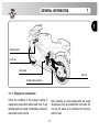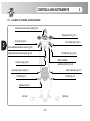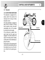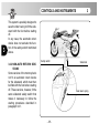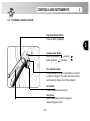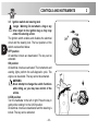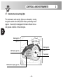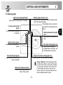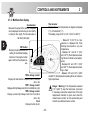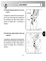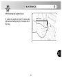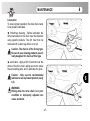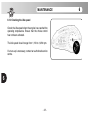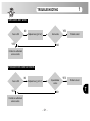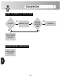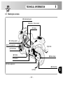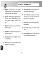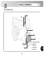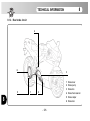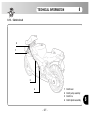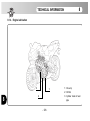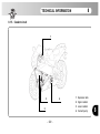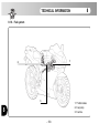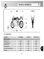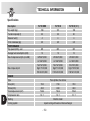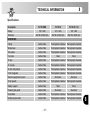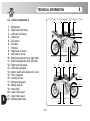
1
Owner’s Manual
Il presente Manuale di uso e manutenzione è disponibile nelle edizioni in lingua sotto specificate:
This Owner’s Manual is available in the languages listed below:
Le présent livret d’utilisation et d’entretien est disponible dans les éditions rédigées dans les langues
spécifiées ci-dessous:
Die vorliegende Bedienungs- und Wartungsanleitung ist in folgenden Sprachen erhältlich:
Las ediciones del presente manual de uso y mantenimiento están disponibles en los siguientes idiomas:
Codice/Code/Code
Bestell-Nr./Código
Edizione Italiana
Italian Edition
Edition Italienne
Italienische Ausgabe
Edición en Italiano
800092869
Edizione Inglese
English Edition
Edition Anglaise
Englische Ausgabe
Edición en Inglés
8A0092869
Edizione Francese
French Edition
Edition Française Französische Ausgabe Edición en Francés 8B0092869
Edizione Tedesca
German Edition
Edition Allemande
Deutsche Ausgabe
Edición en Alemán 8C0092869
Edizione Spagnola
Spanish Edition
Edition Espagnole
Spanische Ausgabe
Edición en Español 8D0092869
Edizione USA
USA Edition
Edition USA
USA Ausgabe
-2-
Edición USA
8A0089042
Dear Customer,
We wish to thank you for your preference and congratulate you on purchasing your new F4.
Your choice is a reward for the passionate effort our technicians have put into giving the F4 functional and aesthetic characteristics that place it above the finest motorcycles currently available on the market, making it an
exclusive and sought-after item.
If, from a purely technical standpoint, the F4 represents an internationally recognized point of reference on
account of the innumerable innovations it introduces, its sleek, timeless design wonderfully combines a glorious past with the new millennium.
The combination of these elements, which was made possible by love of detail, passion, and the desire to
realize a technically and aesthetically superior motorcycle, allows the F4 to soar above passing fashions, giving it the privilege of being considered a unique item.
This manual has been drawn up with a view to providing you with a clear and practical guide to operating and
maintaining your new motorcycle while safeguarding your warranty rights.
The indications contained in the manual will help you make the most of your motorcycle in terms of both performance and operating life. The manual provides useful information on how to take care of your vehicle, and
also describes some routine maintenance operations. Fundamental units such as the engine and the transmission are covered in the Workshop Manuals. Operations involving these parts require specific equipment
and are reserved for skilled personnel. Your dealer possesses the skills, the equipment and the spare parts
that are needed to keep your motorcycle in perfect working order. This manual is to be considered as an integral part of the vehicle, and must be transferred to any new owner together with the vehicle.
-3-
CONTENTS
chap.
Subjects covered
chap.
Subjects covered
1
GENERAL INFORMATION
page
10
2.2
Safety signs - Location
page
27
1.1
Purpose of the manual
10
2.3
Safety - Visual and acoustic signals
35
1.2
Symbols
11
3
CONTROLS AND INSTRUMENTS
36
1.3
Warranty Booklet and Service Coupons
12
3.1
Location of controls and instruments
36
1.4
Identification data
13
3.2
Sidestand
37
1.5
Magnesium parts
15
3.2.1
Auto return sidestand
37
2
SAFETY INFORMATION
16
3.2.2
Non-auto return sidestand
38
2.1
Safety
16
3.3
Handlebar controls, left side
39
2.1.1
How to report a safety-related defect
16
3.4
Handlebar controls, right side
41
2.1.2
Noise emission warranty
16
3.5
Ignition switch and steering lock
44
2.1.3
Note on tampering
16
3.6
Gear lever
45
2.1.4
Information on the emission control
3.7
Instruments and warning lights
46
system
18
3.7.1
Warning lights
47
2.1.5
Safety rules
19
3.7.2
Multifunction display
48
2.1.6
Installing accessories
21
4
OPERATION
49
2.1.7
Vehicle load
21
4.1
Using the motorcycle
49
2.1.8
Modifications
22
4.2
Running-in
50
2.1.9
Competitions
22
4.3
Starting the engine
52
2.1.10 Recommendations for safe riding
23
4.4
Setting the display functions
53
2.1.11 Protective clothing
25
4.5
Selecting the display functions
58
-4-
CONTENTS
chap.
Subjects covered
page
chap.
Subjects covered
4.6
4.7
4.8
4.9
4.10
Refuelling
Glove compartment
Parking the motorcycle
Preriding checks
Riding
60
61
62
64
65
5.8.2
Compression damping hydraulic device
checks
76
5
5.1
5.2
5.3
5.4
5.5
5.6
5.7
5.7.1
5.7.2
ADJUSTMENTS
List of adjustments
Table of adjustments
Adjusting the front brake lever
Adjusting the clutch lever
Adjusting the rearview mirrors
Adjusting the steering damper
Adjusting the front suspension
Spring preload
Rebound damping hydraulic device
(front suspension)
Compression damping hydraulic device
(front suspension)
Adjusting the rear suspension
Rebound damping hydraulic device
(rear suspension)
66
66
68
69
69
70
70
71
72
6.2
Tools and accessories supplied
83
6.3
Table of lubricants and fluids
83
6.4
Removing/fitting the right-hand side
5.7.3
5.8
5.8.1
72
73
74
75
-5-
page
(rear suspension)
75
6
MAINTENANCE
76
6.1
Tables of scheduled maintenance and
fairing
84
6.5
Checking the engine oil level
86
6.5.1
Restoring the engine oil level
87
6.6
Checking the coolant level
88
6.6.1
Restoring the coolant level
89
6.7
Checking the wear of the brake pads
90
6.8
Checking the brake fluid level
91
6.9
Checking the clutch fluid level
92
6.10
Checking the tyres
93
6.11
Checking and lubricating the drive chain
94
6.12
Checking the idle speed
96
6.13
Periodic emission check
97
CONTENTS
chap.
Subjects covered
6.14
Emission control system warranty
obligations
Your warranty rights and obligations
Manufacturer’s warranty coverage
Owner’s warranty responsibilities
Limited warranty on emission control
system
Coverage
Limitations
Limited liability
Legal rights
Additional information
Replacing parts - General information
Replacing the fuses
Replacing the low beam bulb
Replacing the high beam bulb
Replacing the front turn indicator bulbs
Replacing the rear turn indicator bulbs
Replacing the rear light and brake light
bulb
Replacing the number-plate light bulb
6.14.1
6.14.2
6.14.3
6.15
6.15.1
6.15.2
6.15.3
6.15.4
6.15.5
6.16
6.16.1
6.16.2
6.16.3
6.16.4
6.16.5
6.16.6
6.16.7
page
98
98
98
99
100
100
101
102
103
103
104
104
106
107
108
109
110
111
-6-
chap.
Subjects covered
6.17
6.18
6.19
Battery
Cleaning the motorcycle
Prolonged inactivity
page
112
113
114
7
7.1
7.2
TROUBLESHOOTING
Engine problems
Electrical equipment problems
115
115
120
8
8.1
8.1.1
8.1.2
8.1.3
8.1.4
8.1.5
8.1.6
8.2
8.3
TECHNICAL INFORMATION
Motorcycle overview
Front brake circuit
Rear brake circuit
Clutch circuit
Engine lubrication
Coolant circuit
Fuel system
Specifications
Carbon components
123
123
125
126
127
128
129
130
131
138
INDEX
A
C
Accessories, installation
Adjustments
– clutch lever
– front brake lever
– front suspension
– list
– rear suspension
– rearview mirrors
– steering damper
– table
21
Battery
Brakes
– fluid level, check
– front brake circuit
– front brake lever, adjustment
– pads, wear check
– rear brake circuit
Bulbs, replacement of
– front turn indicators
– high beam
– low beam
– number-plate light
– rear light and brake light
– rear turn indicators
112
Carbon components
Chain
– check
– lubrication
Cleaning the motorcycle
Clutch
– circuit
– fluid level, check
– lever, adjustment
Competitions
Controls and instruments, location
Coolant
– level, check
– circuit
– topping up
69
69
71
66
74
70
70
68
B
91
125
69
90
126
138
94
95
113
127
92
69
22
36
88
129
89
D
Damping, hydraulic device
– compression (front suspension)
– compression (rear suspension)
– rebound (front suspension)
– rebound (rear suspension)
Display, multifunction
– selecting functions
– setting functions
108
107
106
111
110
109
-7-
73
75
72
75
48
58
53
INDEX
E
I
Electrical equipment, troubleshooting
Emissions
– control system
– control system warranty
– periodic check
Engine
– lubrication
– oil level, check
– oil level, topping up
– starting
– troubleshooting
120
Fuel system
Fuses, replacement
130
104
Gear lever
Glove compartment
45
61
18
98
97
13
96
44
46
Levels
– brake fluid
– clutch fluid
– coolant
– engine oil
Location of controls and instruments
Lubricants and fluids, table
91
92
88
86
36
83
Magnesium components
Maintenance and checks, tables
Motorcycle overview
15
76
123
Number-plate light, bulb replacement
111
Parking
Preriding checks
Prolonged inactivity
Purpose of manual
62
64
114
10
L
128
86
87
52
115
F
M
G
N
H
Handlebar controls
– left side
– right side
Headlight
– high beam, bulb replacement
– low beam, bulb replacement
Identification data
Idle speed, check
Ignition switch and steering lock
Instruments and warning lights
P
39
41
107
106
-8-
INDEX
R
T
Rear light and brake light,
bulb replacement
Rearview mirrors, adjustment
Refuelling
Replacing parts, general information
Running-in
Tampering, note
Tools and accessories supplied
Topping up
– coolant
– engine oil
Troubleshooting
– electrical equipment
– engine
Turn indicators
– front, bulb replacement
– rear, bulb replacement
Tyres, check
110
70
60
104
50
S
Safety
– recommendations for safe riding
– reporting a safety-related defect
– rules
– signs, location
– visual and acoustic signals
Scheduled maintenance tables
Side fairing, right-hand,
removal/refitting
Sidestand
Specifications
Spring preload
Steering damper, adjustment
Suspensions
– front, adjustment
– rear, adjustment
Symbols
16
23
16
19
27
35
77
16
83
89
87
120
115
108
109
93
V
Vehicle
– load
– modifications
84
37
131
72
70
21
22
W
Warning lights
Warranty
– Booklet and Service Coupons
– emission control system
71
74
11
-9-
47
12
98
GENERAL INFORMATION
1
1.1
Purpose of the manual
In addition to providing directions on operation and maintenance, this manual contains important information about general safety. Read the manual over carefully before first using
the motorcycle.
The manual describes the model with the maximum equipment at print time.
Information marked with the symbol “★” only refers to the F4
750 ORO model.
- 10 -
1
GENERAL INFORMATION
1.2
Symbols
Sections of text that are particularly important in terms of personal safety or possible damage to the motorcycle are marked
with the following symbols:
Danger - Warning: Failure to observe these prescriptions, even in part, may pose a serious hazard to the
rider’s and other people’s safety.
Caution: Failure to observe these prescriptions,
even in part, may result in damage to the motorcycle.
The following symbols give an indication of who is supposed
to perform the different adjustments and/or maintenance operations:
Information on operations that can be carried out by
the user.
Information on operations that are reserved for
authorized personnel.
The “§” symbol refers the reader to the chapter identified by
the number that follows.
- 11 -
1
1
GENERAL INFORMATION
1
1.3
Warranty Booklet and Service Coupons
Besides this Owner’s Manual, the vehicle is accompanied by
a Warranty Booklet containing a Warranty and Pre-Delivery
Certificate and recommended service coupons.
IMPORTANT
The copy the Warranty and Pre-Delivery Certificate to be sent
to MV Agusta Motor must be filled in by the dealer and
returned to the factory within 7 days from the date of registration.
Every time the vehicle is serviced by a dealer, the user must
produce the Warranty Booklet so that the dealer can fill in the
service coupon and return it to the manufacturer within 7 days
from the date of the servicing.
- 12 -
1
1
GENERAL INFORMATION
4) “limited series” number ★
2) engine serial number
1) frame serial number
3) homologation data
1.4 Identification data
1) frame serial number
2) engine serial number
3) homologation data
4) “limited series” number ★
Motorcycle identification
The motorcycle is identified by a frame serial number.
When placing orders for spare parts, in addition to
this number, you may be required to provide the
engine serial number, the colour code and the key
identification.
We recommend writing down all these numbers and
keep them in a safe place.
★ This motorcycle has been produced in a limited
series. Each vehicle is identified by a serial number
stamped on a 24-carat gold plate.
- 13 -
1
GENERAL INFORMATION
1
Motorcycle key identification
A key is supplied in duplicate for both the ignition and all
the locks. Keep the duplicate in a safe place.
Identification of motorcycle colour combination
The colour code must be mentioned when ordering
body spares.
- 14 -
key identification number
1
GENERAL INFORMATION
1
1
Steering base
Front rim
Side plates
Rear rim
Single-sided swingarm
★ 1.5 Magnesium components
Check the condition of the surface coating of
magnesium components before each ride. If any
abraded parts are noted, immediately contact an
authorized service centre.
After travelling on roads treated with salt, wash
the parts as soon as possible with cold water. Do
not use hot water as it enhances the corrosive
action of salt.
- 15 -
SAFETY INFORMATION
2.1. Safety
2
2.1.1 HOW TO REPORT A SAFETY-RELATED
DEFECT
If you believe that your vehicle has a defect capable of causing accidents involving the risk of death
or injury, immediately contact the National
Highway Traffic Safety Administration (NHTSA)
as well as MV AGUSTA Motor S.p.A. If the
NHTSA receives, or has received, similar complaints, it may order an investigation and, if a
safety-related defect is found on a certain number
of vehicles, it may arrange for a recall to be conducted. On no account, however, can the NHTSA
be involved in any controversy arising between
you and your dealer or MV AGUSTA Motor S.p.A.
To contact the NHTSA, you may call the toll-free
Auto Safety Hotline at 1-800-424-9393 (or 3660123 in the Washington D.C. area), or send a letter to the following address: NHTSA, U.S.
Department of Transportation, Washington, D.C.
20590.
The Hotline may also provide you with additional
information on motor vehicle safety.
2
2.1.2 NOISE EMISSION WARRANTY
MV AGUSTA Motor S.p.A. warrants that, at the
time of sale, the exhaust system conformed to all
applicable U.S. EPA (Environmental Protection
Agency) noise control regulations. The warranty
applies to the first retail purchaser of the exhaust
system and to all subsequent buyers. Any warranty claims must be addressed to:
Cagiva U.S.A., Davisville Road, Willow Grove, PA
19090-4139.
2.1.3 NOTE ON TAMPERING
Tampering with the noise control system is prohibited. In particular, federal law prohibits the following acts:
1. The removal or rendering inoperative, other
than for purposes of maintenance, repair, or
replacement, of any device or element of
design incorporated into any new vehicle for
the purpose of noise control prior to its sale or
delivery to the ultimate purchaser or while it is
in use.
- 16 -
SAFETY INFORMATION
2. The use of the vehicle after such device or
element of design has been removed or rendered inoperative.
Acts presumed to constitute tampering include:
1. The removal or piercing of the exhaust
silencer, the diaphragm, the manifolds, or any
other components involved in the transmission
of exhaust gases.
2. The removal or piercing of any part of the
intake system.
3. Poor maintenance.
4. The replacement of any movable parts of the
vehicle or of any intake or exhaust components with parts or components other than
those prescribed by the manufacturer.
NOTE
We recommend overhauling and if necessary
repairing or replacing the product if a marked
increase in noise levels is noted.
Failure to do this may cause the owner to incur
the penalties provided for by local and national
legislation.
- 17 -
2
WARNING
Highway Code provisions vary from
country to country. Make sure of the content of local regulations before using the
vehicle.
2
SAFETY INFORMATION
2
2.1.4 INFORMATION ON THE EMISSION CONTROL SYSTEM
The combustion process produces carbon
monoxide and hydrocarbons. Hydrocarbon control is particularly important in that, under certain
conditions and when exposed to direct sunlight,
hydrocarbons undergo reactions which lead to the
formation of photochemical smog. Carbon
monoxide does not react in the same way, but it is
highly toxic. MV Agusta uses a sequential multipoint electronic injection system and other methods designed to cut carbon monoxide and hydrocarbon emissions.
Exhaust emission control system
The exhaust emission control system is made up
of the sequential multipoint injection (SMPI) system, which requires no adjustment. The exhaust
emission control system is distinct from the
crankcase emission control system.
2
system designed to prevent the release of
crankcase emissions into the atmosphere. Blowby gases return to the combustion chamber via
the air filter and the injection system.
Problems relating to the vehicle’s emissions
Should the vehicle show any of the following
symptoms, contact your MV Agusta dealer to
have it checked and if necessary repaired:
1) Engine is difficult to start or stalls after starting.
2) Idle speed is erratic.
3) Misfiring or backfiring during acceleration.
4) Afterburning.
5) Poor performance (driveability) and excessive
consumption.
Crankcase emission control system
The engine is equipped with a closed-crankcase
- 18 -
SAFETY INFORMATION
2.1.5 SAFETY RULES
IMPORTANT: READ BEFORE USE
– Before riding, carefully read this manual so as
to familiarize yourself with the controls, characteristics, functionalities and limits of the
vehicle. The manual is not aimed at providing
information on all possible techniques and
methods required for safe riding.
– Do not attach a sidecar, a trailer or any other
accessory to the motorcycle. Do not modify
the vehicle in any way. Failure to observe this
prescription may make the vehicle unstable
and cause serious accidents.
– To ensure maximum reliability and maintain
the vehicle in perfect working order, it is essential to perform the servicing detailed in the
Scheduled Maintenance Table and to follow all
the prescriptions provided in this manual.
For further information, apply to your dealer,
who possesses the necessary technical skills
2
and the workshop manual.
– The introduction of structural improvements
and performance enhancements in the production process may cause the structure of the
vehicle to depart slightly from the illustrations
and texts contained in this manual.
- 19 -
2
SAFETY INFORMATION
Do not use the motorcycle, nor try to service it,
if you do not possess the necessary skills.
2
Full control of the motorcycle is fundamental to
safe riding. Concentration and a perfect physical
condition are essential requirements for the rider.
The road and weather conditions should also be
taken into account.
Always wear suitable clothes, especially when
travelling by night (e.g. garments with fluorescent
bands).
Always wear a helmet, even on short rides.
When travelling during daylight, keep the low
beam on if allowed by local regulations.
Do not attach objects or wear garments that
could adversely affect control and handling of the
motorcycle.
When refuelling, switch off the engine and
refrain from smoking.
When refuelling, avoid spilling the fuel onto the
tank and the exhaust pipes.
2
When refuelling, stay away from the vehicle to
avoid inhaling harmful fumes. Should the fuel
come into contact with the skin or clothes, immediately wash with water and change the contaminated garments.
Some parts of the vehicle become very hot
during use. Avoid contact with these parts and
keep the motorcycle out of the reach of children.
Always park the motorcycle safely and avoid
leaving it unattended while the ignition key is in
the dashboard.
Park the vehicle where it is unlikely to be
bumped into or damaged.
To prevent the vehicle from tipping over, never
park it on soft or uneven ground.
Do not start the engine in closed places.
Exhaust gases are toxic and can quickly saturate
the air and cause fainting or even death.
Before starting the engine in a closed place,
ensure that the area is well ventilated.
- 20 -
2
SAFETY INFORMATION
While the vehicle is in motion, always rest the
feet on the specially designed supports.
While riding, always keep both hands on the
handlebars.
Maximum performance of the standard brake
pads is obtained on dry roads. Also available on
request are pads that ensure optimum performance even on wet roads (for further information
contact an authorized service centre).
2.1.6 INSTALLING ACCESSORIES
MV Agusta provides a range of accessories specially designed for your vehicle. It is essential that
these accessories are installed by an authorized
service centre. The use of non-genuine accessories can make the vehicle unsafe by reducing
its handling, stability and the effectiveness of the
braking system. For this reason, the installation of
any non-genuine accessory makes the warranty
null and void and relieves MV Agusta of all
responsibility.
2.1.7 VEHICLE LOAD
The F4 S version is designed for use by the rider
only, whereas the F4 S 1+1 version can also seat
a passenger. To use the vehicle in complete safety and in compliance with the Highway Code, it is
essential that the following maximum load conditions are never exceeded:
F4 S
F4 S 1+1
325 kg
405 kg
(717 lbs)
(893 lbs)
These values are also shown on the plate fixed to
the left side of the steering head tube.
- 21 -
2
SAFETY INFORMATION
2.1.8 MODIFICATIONS
2
2
Highway Code for which MV Agusta cannot be
held responsible.
Any modifications made to the vehicle (e.g. alteration and/or removal of components) can make
the vehicle unsafe or unlawful. Modifying the vehicle immediately voids the warranty and relieves
MV Agusta of all responsibility.
2.1.9 COMPETITIONS
WARNING
Riding the vehicle in competitions
requires considerable skill and experience as well as an accurate setup of the
motorcycle.
MV Agusta has designed a number of special
components for use in competitions and/or sporting events. The use of such components is strictly limited to areas closed to traffic. Failure to
observe this restriction constitutes a breach of the
- 22 -
SAFETY INFORMATION
2.1.10 RECOMMENDATIONS FOR SAFE RIDING
Besides being a means of transport, your motorcycle is a source of recreation and excitement.
However, the configuration of the vehicle does not
exclude a certain amount of risk. To ensure maximum safety, in addition to scrupulously observing
the indications provided in the previous paragraphs, it is essential to take a few additional precautions.
In particular:
Before starting off
Follow all the directions given in the section “PREDELIVERY CHECKS”. Conduct an overall check
of all safety-related aspects of the motorcycle.
Familiarizing with the vehicle
The rider’s ability and his mechanical skills form
the basis of riding safety. It is advisable to practise
riding in areas without traffic until you have
2
become familiar with the vehicle and its controls.
Remember: practice leads to perfection.
Being aware of one’s limits
When riding, never exceed your limits nor those
imposed by law. Being aware of your limits and
acting accordingly will help you avoid accidents.
Adverse weather conditions
Be very careful when riding in adverse weather
conditions. On wet roads, for example, the braking distance doubles as a result of reduced tyre
traction. It is therefore necessary to travel at moderate speed and avoid abrupt braking and acceleration. Pay particular attention when riding on
slippery surfaces such as road markings, manholes, level crossings, bridges, gratings, etc.
Considering that a motorcycle cannot provide the
same degree of shock protection as a motor vehicle, it is essential to adopt a “defensive” riding attitude, particularly in the adverse weather conditions described above.
- 23 -
2
SAFETY INFORMATION
2
Before changing lanes, besides using the
rearview mirror, turn your head slightly and glance
back to make sure that the road is clear.
Relying on the rearview mirror alone puts the rider
at risk of misjudging the distance and speed of the
vehicles at the back or not seeing them at all.
Change gears as necessary to ensure that the
proper gear ratio is chosen in all riding conditions,
allowing the engine to revolve at optimum speed
at all times.
Avoid high gear ratios when travelling at reduced
speed (excessively low rpm) as well as low gear
ratios when travelling at high speed (excessively
high rpm).
Special attention should be given to the braking system, which plays a key role in ensuring
safety. When braking, always take account of the
speed of the vehicle and the condition of the road
surface.
The braking action should always be applied gen-
2
tly and gradually to both wheels, an ability that
can only be learned from experience.
Performing this operation and, more in general,
riding the vehicle always requires the utmost care.
Therefore, caution should be exercised by all
users, and in particular by inexperienced riders.
When covering long distances downhill,
reduce the speed of the vehicle by closing the
throttle and using a low gear ratio to take advantage of the exhaust brake. The front and rear
brakes should also be used with moderation, in
order to prevent them from overheating and
reduce their effectiveness.
When rapid acceleration is required (e.g. when
overtaking), change down to obtain better pickup.
When the engine is running at high speed,
gearing down several times in rapid succession
can cause the engine to race. As a result, the rear
driving wheel may lock, making the vehicle difficult to control and causing damage to the engine.
- 24 -
SAFETY INFORMATION
Keep at a safe distance from the preceding
vehicles and adjust the speed to the weather and
traffic conditions. Remember that, as the vehicle
picks up speed, the stopping distance increases
and the motorcycle becomes more difficult to control. In any case, never exceed the speed limits
imposed by the Highway Code.
It is strictly forbidden to drink alcoholic beverages or take drugs before riding. Even very small
amounts of these substances adversely affect the
rider’s ability to control the vehicle.
2.1.11 PROTECTIVE CLOTHING
Helmet wearing is compulsory under the Highway
Code. The helmet must be securely fastened and,
if it is of the open-face type, specially designed
glasses are also required.
Suitable protective clothing, though not required
by law, is strongly recommended.
In particular, the following items should be worn:
2
A strong, close-fitting and easy-to-fasten vest.
A collar for protecting the throat from the air
flow.
Supple, reinforced gloves providing both sensitivity and protection.
Strong, close-fitting trousers covering the legs
completely.
Soft, reinforced boots providing both sensitivity and protection.
The items mentioned above are available from
any specialized shop.
We recommend buying brightly coloured clothes,
as they make the rider easier to see at night and
in the fog.
In any case, the clothes must allow complete freedom of movement and not hamper the rider in any
way. In addition, they must have no loose parts
capable of catching in the control levers, the
footrests, the wheels, the drive chain, etc.
- 25 -
2
SAFETY INFORMATION
2
WARNING
Protective clothes do not afford complete protection against the risk of personal injury in case of accident.
It is therefore essential not to be
deceived by the false sense of security
that is provided by motorcycle clothing.
When riding, always adopt a cautious
attitude and follow the recommendations given in the previous paragraphs.
- 26 -
2
2
SAFETY INFORMATION
2.2
1
2
3
4
5
-
Safety signs - Location
Windscreen function
Battery warning
Unleaded petrol
Chain adjustment
Information on gas emissions,
LH and RH exhausts
6 - Information on emission control
7 - Emission control
8 - Tyre pressure, single-seat F4
9 - Tyre pressure, two-seat F4
10 - Manufacturer’s data, two-seat
F4
11 - Manufacturer’s data, singleseat F4
12 - Rearview mirrors
13 - Rear shock absorber
8-9
12 1 12
2
3
5
2
7
6
5
10 - 11
4
13
- 27 -
SAFETY INFORMATION
2
ADHESIVE LABEL – WINDSCREEN WARNING
2
CUPOLINO CON FUNZIONE AERODINAMICA, NON GUARDARE ATTRAVERSO IL VETRINO DURANTE
LA MARCIA. LA NON OSSERVANZA DI QUESTO AVVISO POTREBBE CAUSARE SERIE CONSEGUENZE ALLE PERSONE.
PER LA PULIZIA DEL PLEXIGLASS UTILIZZARE SOLAMENTE ACQUA E SAPONE , NON UTILIZZARE SOLVENTI.
WINDSCREEN HAS AERODYNAMIC FUNCTION ONLY, DO NOT LOOK THROUGH IT WHILE RIDING.
FAILURE TO RESPECT THIS COULD CAUSE SERIOUS BODILY HARM. USE ONLY SOAP AND WATER
FOR CLEANING SCREEN - NO SOLVENTS. SEE OWNER'S MANUAL.
ADHESIVE LABEL – BATTERY WARNING
- 28 -
SAFETY INFORMATION
2
ADHESIVE LABEL – UNLEADED PETROL
2
ADHESIVE LABEL – CHAIN ADJUSTMENT
- 29 -
SAFETY INFORMATION
2
STAMPING ON LH SILENCER – GAS EMISSION INFORMATION, LH EXHAUST
MOTORCYCLE EXHAUST SYSTEM NOISE EMISSION CONTROL INFORMATION
THIS CAGIVA EXHAUST SYSTEM, 800090377 MEETS US EPA NOISE EMISSION
REQUIREMENT OF 80 dBA FOR THE FOLLOWING
MOTORCYCLES: CAG44F0750.INSTALLATION OF THIS EXHAUST SYSTEM ON
MOTORCYCLE MODELS NOT SPECIFIED MAY VIOLATE FEDERAL LAW
2
STAMPING ON RH SILENCER – GAS EMISSION INFORMATION, RH EXHAUST
MOTORCYCLE EXHAUST SYSTEM NOISE EMISSION CONTROL INFORMATION
THIS CAGIVA EXHAUST SYSTEM, 800090376 MEETS US EPA NOISE EMISSION
REQUIREMENT OF 80 dBA FOR THE FOLLOWING
MOTORCYCLES: CAG44F0750.INSTALLATION OF THIS EXHAUST SYSTEM ON
MOTORCYCLE MODELS NOT SPECIFIED MAY VIOLATE FEDERAL LAW
- 30 -
SAFETY INFORMATION
2
ADHESIVE LABEL – EMISSION CONTROL
2
ADHESIVE LABEL – TYRE PRESSURE, SINGLE-SEAT F4
- 31 -
2
SAFETY INFORMATION
ADHESIVE LABEL – TYRE PRESSURE, TWOSEAT F4
2
ADHESIVE LABEL –
DATA, SINGLE-SEAT F4
MANUFACTURER’S
MANUFACTURED by CAGIVA Motor s.p.a.
DATE :
GVWR 717 Ibs / 325 kg.
GAWR F 331 Ibs - 150 kg. - GAWR R 386 Ibs / 175 kg.
This vehicle conforms to all applicable Federal Motor Vehicle Safety
Standards in effect on the date of manufacture shown above
Vehicle Type : MOTORCYCLE
VIN :
- 32 -
2
SAFETY INFORMATION
ADHESIVE LABEL –
DATA, TWO-SEAT F4 S
MANUFACTURER’S
MANUFACTURED by CAGIVA Motor s.p.a.
DATE :
GVWR 893 Ibs / 405 kg.
GAWR F 342 Ibs - 155 kg. - GAWR R 551 Ibs / 250 kg.
This vehicle conforms to all applicable Federal Motor Vehicle Safety
Standards in effect on the date of manufacture shown above
Vehicle Type : MOTORCYCLE
VIN :
ADHESIVE LABEL – REARVIEW MIRRORS
OBJECTS IN MIRROR ARE CLOSER
THAN THEY APPEAR
- 33 -
2
2
SAFETY INFORMATION
ADHESIVE
ABSORBER
LABEL
–
REAR
SHOCK
WARNING
2
CONTAINS HIGHLY COMPRESSED GAS
USE ONLY PERFECTLY DRY NITROGEN GAS
OTHER GASES MAY CAUSE EXPLOSION
DO NOT INCINERATE REFER TO OWNER S
MANUAL FOR REGULATING GAS
SACHS
- 34 -
SAFETY INFORMATION
2.3
Safety - Visual and acoustic
signals
2
Turn indicators (§ 3.3)
Parking light, low and high
beams (§ 3.3)
Before each ride, it is essential to
verify the operation of the visual
and acoustic signals.
Parking light (§ 3.3) and brake light
(lights up operating the brakes)
Horn (§ 3.3)
Turn indicators (§ 3.3)
Plate light (lights up when parking
lights are turned on)
Front side reflector
Rear reflector
Rear side reflector
- 35 -
2
CONTROLS AND INSTRUMENTS
3.1
3
Location of controls and instruments
Instruments and warning lights (§ 3.7)
Rearview mirror (§ 5.1)
Clutch lever (§ 5.1)
3
Front brake lever (§ 5.1)
Left handlebar electrical controls (§ 3.3)
Ignition switch and steering lock (§ 3.5)
Throttle twist grip (§ 3.4)
Right handlebar
electrical controls (§ 3.4)
Fuel tank cap (§ 4.6)
Rear brake lever (§ 5.1)
Gear lever (§ 3.6 and § 5.1)
Footrest (§ 5.1)
Footrest (§ 5.1)
Sidestand (§ 3.2)
Right side
Left side
- 36 -
CONTROLS AND INSTRUMENTS
3.2
3
Sidestand
3.2.1 AUTO RETURN SIDESTAND
The sidestand is equipped with a
safety switch that prevents the
motorcycle from moving off while
the stand is down.
If the rider attempts to engage the
gears while the engine is running
and the stand is down, the switch
automatically turns off the engine
by cutting the current supply.
If the motorcycle is parked (sidestand down) and the gears are
engaged, the switch prevents the
engine from being started, thereby
avoiding the risk of accidentally toppling the vehicle.
Some versions of the motorcycle fit
a device that automatically pulls up
the sidestand as soon as the vehicle is lifted from the parking position.
3
Safety switch
Sidestand
Dual return spring
- 37 -
CONTROLS AND INSTRUMENTS
3
3
This system is specially designed to
save the rider having to lift the sidestand with the foot before starting
off.
In any case, the automatic return
device does not exclude the function of the safety switch mentioned
above.
Safety switch
3.2.2 NON-AUTO RETURN SIDESTAND
Some versions of the motorcycle do
not fit an automatic return device
for the sidestand, which must then
be lifted with the foot before starting
off. These versions, however, fit the
same sidestand safety switch that
makes it necessary to follow the
starting procedures described in
paragraph 3.2.1.
Sidestand
Dual return spring
- 38 -
CONTROLS AND INSTRUMENTS
3.3
3
Handlebar controls, left side
High beam flasher button
Press the button repeatedly
3
Low/high beam button
Button not pressed in
: low beam
Button pressed in
: high beam
Turn indicator switch
Shifting the lever to the left or right switches on the left
or right turn indicators. The switch then returns to the
central position. Press to turn off the indicators.
Horn button
Press to operate the warning horn.
Clutch lever
Move towards/away from the handgrip to
release/engage the clutch.
- 39 -
CONTROLS AND INSTRUMENTS
3
High beam flasher button
It is used to attract the attention of other road users in case of danger. When the high beam is on, the function is inactive.
3
Low/high beam button
Under normal conditions, the low beam is on. The high beam can be switched on by pressing the button
when allowed by the traffic and road conditions.
Turn indicator switch
It is used to show the rider’s intention to change direction or lane.
WARNING
Failure to switch the turn indicators on or off at the right time may cause an accident in that
the other road users may draw incorrect conclusions as to direction of motion the vehicle.
Always switch on the indicators before turning or changing lanes. Then be sure to switch off
the indicators after completing the operation.
Horn button
It is used to attract the attention of other road users in case of danger.
Clutch lever
It engages/disengages the clutch through a hydraulically controlled device.
- 40 -
CONTROLS AND INSTRUMENTS
3.4
3
Handlebar controls, right side
Engine stop switch
Stops the engine and prevents it from being restarted.
Engine start button
Starts the engine. To be released as soon as the engine starts.
When the engine is running, pressing the button selects the display functions.
Cold start (choke) lever
Rotate clockwise when cold starting. After a few seconds, bring
the lever back to the home position.
Throttle twist grip
Rotate to control the engine fuel supply.
Front brake lever
Pull to the handgrip to operate the front brake.
- 41 -
3
CONTROLS AND INSTRUMENTS
3
Engine stop switch
It is used to switch off the engine in an emergency. The ignition circuit is disabled, preventing the engine
from being restarted. To be able to restart the engine, bring the switch back to the home position.
NOTE
Under normal conditions, do not use this switch to shut off the engine.
3
Engine start button
It is used to start the engine and, when the engine is running, to select the different functions of the display installed on the instrument panel.
DANGER
To avoid damaging the electrical equipment, be sure not to hold down the button for longer
than 5 consecutive seconds.
If, after several attempts, the engine does not start, refer to the chapter “TROUBLESHOOTING” later in this manual.
Cold start (choke) lever
It facilitates cold starts by acting on the fuel supply.
- 42 -
CONTROLS AND INSTRUMENTS
3
NOTE
This function must remain active only for a short time depending on the engine and outside temperatures. As soon as the idle speed keeps the engine running, it is advisable to disable the control.
Throttle twist grip
It controls the fuel supply, making it possible to change the speed of the engine. To operate the device,
rotate the handgrip from the home position, corresponding to the idle speed.
When cold starting (choke on), rotating the handgrip towards the throttle closing position brings the
choke lever back to the home position.
Front brake lever
It controls a hydraulic circuit that operates the front wheel braking system.
- 43 -
3
CONTROLS AND INSTRUMENTS
3.5
3
Ignition switch and steering lock
Danger - Warning: Do not attach a ring or any
other object to the ignition key as they may
hinder the steering action.
The ignition switch enables and disables the electrical
circuit and the steering lock. The four positions of the
switch are described below.
OFF position
All electrical circuits are deactivated. The key can be
extracted.
ON position
All electrical circuits are activated. The instruments and
warning lights perform the self-diagnostic cycle. The
engine can be started. The key cannot be extracted.
WARNING
Never attempt to change the switch functions
while riding, as you may lose control of the
vehicle.
LOCK position
Turn the handlebar to the left or right. Press the key in
gently while rotating it to the LOCK position.
All electrical circuits are deactivated and the steering is
locked. The key can be extracted.
- 44 -
3
CONTROLS AND INSTRUMENTS
3
P (PARKING) position
Turn the key from the LOCK position to the P position.
All electrical circuits are deactivated except the parking
lights. The steering is locked. The key can be extracted.
3
3.6
Gear lever
The N (neutral) position is indicated by the related warning light on the instrument panel.
To change into first gear, shift the lever down.
To change into second gear, shift the lever up. Shifting
the lever up repeatedly engages all the other gears in
succession up to the sixth speed.
- 45 -
CONTROLS AND INSTRUMENTS
3.7
Instruments and warning lights
The instruments and warning lights are activated by turning
the ignition switch to the ON position. After a preliminary check
(approx. 7 seconds) the displayed information reflects the current general condition of the motorcycle.
3
Warning lights
(§3.7.1.)
Warning light
(§3.7.1.)
SET button (§3.7.2.)
Tachometer
Multifunction display (§3.7.2.)
- 46 -
3
CONTROLS AND INSTRUMENTS
3
3.7.1 Warning lights
Battery charge indicator (red)
Lights up when the alternator does not supply enough
current to charge the battery.
If the indicator comes on while riding, contact an authorized service
centre.
High beam warning light (blue)
Lights up when the high beam is activated.
Low beam warning light
(green)
Comes on when the low beam
is activated.
Sidestand down warning light
(red)
Lights up when the sidestand is
down.
Neutral indicator (green)
Lights up when the gears are in
neutral.
Rev limiter warning light (red)
Lights up when the engine
speed exceeds 12,700 rpm. The
rev limiter trips at 13,100 rpm.
Engine oil pressure warning light (red)
Lights up when the oil pressure is insufficient.
Turn indicator light (green)
Lights up when the turn indicators are activated.
Danger - Warning: If the warning light comes
on while riding, stop the motorcycle immediately. Check and if necessary restore the oil level.
If the warning light comes on even if the oil
level is correct, do not resume riding and contact an authorized service centre.
Reserve fuel indicator (amber)
Comes on when approximately
4 litres of fuel are left..
- 47 -
3
CONTROLS AND INSTRUMENTS
3
3.7.2 Multifunction display
Thermometer
Displays the coolant temperature in degrees centigrade
(° C) or Fahrenheit (° F).
The display range is 40° to 140° C (104° to 284° F):
Speedometer
Measures the speed of the vehicle. The speed
can be displayed in kilometres per hour (km/h)
or miles per hour (mph). The full-scale value is
320 km/h (200 mph).
3
- Below 40° C (104° F) no temperature is displayed but three
blinking lines denote a very low
temperature.
- Between 40° and 49° C (104°
and 120° F) the temperature reading blinks to indicate a low temperature.
- Between 50° and 105° C (122°
and 221° F) the temperature reading is fixed.
- Between 106° and 140° C (223°
and 284° F) the temperature reading blinks to indicate a
high temperature.
SET button
Pressing the button allows the
setting of the different display
functions. Pressing the button
again confirms the entered values.
TOTAL mileage counter
Displays the total distance covered: from 0 to 999,000
(km or mi)
TRIP 1 mileage counter
Displays a first trip mileage count: from 0 to 9,999.9 (km or mi)
TRIP 2 mileage counter
Displays a second trip mileage count: from 0 to 9,999.9
(km or mi)
Clock
Displays the time (0÷24)
Danger - Warning: If the temperature exceeds
115° C (239° F), stop the motorcycle, check and
if necessary restore the coolant level. If the high
temperature indication is given even when the
coolant level is correct, do not resume riding and
contact an authorized service centre.
- 48 -
OPERATION
4.1
4
Using the motorcycle
This section provides the basic information needed to correctly operate the motorcycle:
-
Running-in (§ 4.2)
Starting the engine (§ 4.3)
Setting the display functions (§ 4.4)
Selecting the display functions (§ 4.5)
Refuelling (§ 4.6)
Glove compartment (§ 4.7)
Parking the motorcycle (§ 4.8)
Preriding checks (§ 4.9)
Riding (§ 4.10)
4
- 49 -
OPERATION
4.2
Running-in
Caution: Failure to observe the indications
provided below can reduce performance and
shorten the life of the motorcycle.
4
Running-in is generally considered to apply only to the
engine. In fact, it should be regarded as an essential
phase for other important parts such as the tyres, the
brakes and the drive chain. During the very first kilometres, adopt a relaxed riding style.
❏ 0 to 500 km (0 to 300 mi) (A)
Frequently change the engine speed. If possible, prefer
hilly routes with gentle slopes and many bends. Avoid
long straight stretches.
- 50 -
4
OPERATION
4
❏ 500 to 1000 km (300 to 600 mi)
Avoid subjecting the engine to prolonged strain.
4
❏ 1000 to 2500 km (600 to 1600 mi)
Higher engine performance can be demanded, but it is
advisable not to exceed the engine speed shown in the
figure..
- 51 -
OPERATION
4.3
Starting the engine
Caution: Avoid warming up the engine while
the vehicle is stationary. It is advisable to bring
the engine to the working temperature by riding at reduced speed.
Turn the ignition switch to the ON position. The
instruments and the warning lights will go through the
self-diagnostic cycle. Make sure the gears are in neutral.
4
4
❏ Cold starting
Rotate the CHOKE lever without turning the throttle
twist grip and then press the start button.
As soon as the engine starts, release the button and,
after warming up the engine for a short time, bring back
the CHOKE lever to the home position.
❏ Hot starting
Press the start button without turning the throttle twist
grip.
As soon as the engine starts, release the button.
Caution: Do not press the start button for
longer than 5 consecutive seconds.
- 52 -
CHOKE lever
OPERATION
4
4.4 Setting the display functions
The following functions can be set: clock, speedometer
and thermometer units.
WARNING
The operation must be performed while the
engine is running, the gears are in neutral, the
motorcycle is stationary, and with the feet on
the ground. Do not set the display functions
while riding.
❏ Clock (hours and minutes)
Repeatedly press the button until the time is displayed.
Press the SET button – the first hour digit will start
blinking.
- 53 -
4
OPERATION
Hold down the button and release it as soon as the
desired figure is displayed.
Repeat the procedure to set the second hour digit
and the first and second minute digits.
NOTE
To quickly cycle through the selected digit, hold the
start button depressed for longer than two seconds.
4
NOTE
The instrument panel has an integrated memory
which retains all the parameters even when the
engine is not running. Except for the clock, which is
reset, all the parameters are retained even when the
battery is disconnected.
Press SET to confirm the time and exit the set (blinking) mode.
- 54 -
4
OPERATION
4
❏ Speedometer (km/h - mph)
Repeatedly press the button until the TOTAL counter
function is displayed.
4
Press the SET button. The speedometer unit will
start blinking.
- 55 -
OPERATION
Press the button to toggle between km/h and mph.
Changing the speedometer unit also changes the units
for the total and trip mileage counters.
4
Press SET to confirm the speedometer unit. The
thermometer unit will start blinking, indicating that the
display is ready for the next setting.
- 56 -
4
OPERATION
4
❏ Thermometer (° C - ° F)
Press the button to toggle between ° C and ° F.
4
Press SET to confirm the temperature unit.
- 57 -
OPERATION
4.5
Selecting the display functions
Selectable functions include the
TOTAL, TRIP 1 and TRIP 2 mileage
counters, and the clock.
The selection must be performed
while the engine is running.
4
Pressing the button repeatedly
cycles through the different functions.
- 58 -
4
OPERATION
4
❏ Resetting the trip mileage counters
The TRIP 1 and TRIP 2 counters can be reset as follows:
Press the button for longer than four seconds. The
mileage will start blinking.
4
Pressing the button for less than four seconds sets
the mileage to zero. If, on the other hand, the button is
pressed for longer than four seconds the entire resetting
procedure is cancelled.
- 59 -
OPERATION
4.6
Refuelling
Danger - Warning: When refuelling, switch off
the engine, avoid smoking, and keep away
from flames, sparks and heat sources.
WARNING
Petrol and its fumes are highly toxic and flammable. Avoid contact and inhalation.
4
Caution: Only use high-octane unleaded
petrol. A green dot on the lower side of the
tank cap serves as a reminder of this.
Lift the dust cover.
Insert the key into the lock, rotate it clockwise and lift
the tank cap.
After refuelling, press down the tank cap while rotating the key clockwise to facilitate the locking. Then
release the key and extract it.
- 60 -
4
OPERATION
4
WARNING
Overfilling the tank may cause the fuel to
overflow as a result of the expansion due to
the heat from the engine or to exposure to
sunlight. Fuel spills can catch fire. The level
of the fuel in the tank must never be higher
than the base of the filler.
4
4.7
Glove compartment
Insert the key into the lock.
Press down the tail section end while turning the
key clockwise.
Slightly lift the tail section off the rear end. Slide the
tail section backwards and overturn it onto the fuel
tank .
- 61 -
OPERATION
4.8
4
Parking the motorcycle
❑ Using the sidestand
4
Care - Caution: Park the motorcycle safely
on solid ground.
On slopes, engage the bottom gear and park
the vehicle so that the front wheel faces
uphill. Remember to put the gear lever in the
neutral position before restarting the engine.
Never leave the vehicle unattended while the
ignition key is in the dashboard.
In versions equipped with an auto return
sidestand, even a light blow can accidentally
operate the return device and cause the
vehicle to topple over.
Using a foot, lower the sidestand to travel end and
then slowly tip the motorcycle to bring the stand support foot into contact with the ground.
NOTE
When parking a vehicle equipped with an auto
return sidestand, be sure to bring the stand all the
way down with the foot and to keep it in position
until the vehicle is stable.
- 62 -
WARNING
Do not sit on the vehicle when it is
parked on the sidestand, as your
full weight would rest on the vehicle’s only support.
WARNING
Before moving off, ensure that the
sidestand warning light on the
instrument panel goes out. In any
case, make sure that the stand has
been retracted.
OPERATION
4
❏ Using the rear stand
Insert the stand pin into the rear wheel axle hole
on the left side of the motorcycle. Rest the stand
on the ground and, pressing down on the stand,
lift the vehicle until it reaches a stable condition.
4
- 63 -
OPERATION
4.9
Preriding checks
A motorcycle can be in good running order and
then become unexpectedly unreliable even if
unused (e.g. deflation of the tyres). It is therefore
important to carry out the checks described in the
table below before each ride. A few moments
taken to carry out these checks will help you
maintain your motorcycle safe and in perfect
working order.
4
Brakes
Check fluid level (§ 6.8).
Check for fluid leakages.
Pull lever and press pedal to check brake operation.
Check pads for wear (§ 6.7)
Clutch lever
Check fluid level (§ 6.9).
Check for fluid leakages.
Pull lever and check that it moves smoothly and gradually.
Throttle twist grip
Check that grip rotates smoothly and returns to closed
position when released.
Steering damper
Always check adjustment (§ 5.6).
Engine start button / stop switch
Check operation (§ 3.4).
Lights, visual and acoustic signals
Check operation.
Tyres
Check inflating pressure and wear (§ 6.10).
Suspensions
Check adjustment (§ 5.7 and § 5.8).
Drive chain
Check adjustment and lubrication (§ 6.11).
Coolant
Check level (§6.6).
Check for leakages.
Engine oil
Check level (§ 6.5).
Check for leakages.
Sidestand
Check return to home position.
★ Magnesium components
Check condition of surface coating (§ 1.5).
- 64 -
4
OPERATION
4
4.10 Riding
Riding a motorcycle requires experience and concentration.
Inexperienced riders should undergo a period of training and attend an introductory course consisting of
theoretical lessons as well as practical riding sessions in areas closed to traffic.
The instructor’s advice will help the novice rider become familiar with the basics of riding safety.
Relying on the advice of persons other than a qualified riding instructor, even if possessing specific
knowledge, may prove to be useless or even dangerous, especially if the practical training takes place
in an area open to traffic.
4
WARNING
While riding, always observe the safety prescriptions described in paragraph 2.1.10 of this
manual.
- 65 -
ADJUSTMENTS
5.1
List of adjustments
There are many adjustments that can significantly
improve the ergonomics, geometry and safety of the
motorcycle.
Some of these can only be performed by skilled personnel at authorized service centres.
5
WARNING
To avoid losing control of the vehicle while
riding, be sure to always keep both hands on
the handlebars. All adjustments must be performed when the vehicle is stationary.
- 66 -
5
5
ADJUSTMENTS
(F) Rearview mirror adjustment (§ 5.5)
(G) Steering damper adjustment
(§ 5.6)
(A) Clutch lever adjustment (§ 5.4)
(D) Gear lever adjustment (§ 5.2)
(F) Rearview mirror adjustment (§ 5.5)
(L) Rear suspension adjustment
(§ 5.8)
★ (C) Right-hand footrest
adjustment (§5.2.)
5
(E) Rear brake lever adjustment (§ 5.2)
(B) Front brake lever adjustment (§ 5.3)
(N) Headlight
adjustment (§ 5.2)
(M) Drive chain
adjustment (§ 5.2)
★ (C) Left-hand footrest
adjustment (§ 5.2)
(H) Front suspension
adjustment (§ 5.2)
- 67 -
ADJUSTMENTS
5.2
Table of adjustments
A - Clutch lever adjustment: Optimizes the grip
to suit the rider’s needs (§ 5.4).
B - Front brake lever adjustment: Optimizes
the grip to suit the rider’s needs (§ 5.3).
5
5
H - Front suspension adjustment: The following can be adjusted to adapt the response of the
suspension to the rider’s preference:
- spring preload (§ 5.7)
- rebound damping hydraulic device (§ 5.7)
- compression damping hydraulic device (§ 5.7)
C - LH and RH footrest adjustment: Optimizes
the position of the feet to suit the rider’s needs ★.
L - Rear suspension adjustment: The following
can be adjusted to adapt the response of the suspension to the rider’s preference:
D - Gear lever adjustment: Optimizes the movement of the lever to suit the rider’s needs.
- spring preload
- geometry height
E - Rear brake lever adjustment: Optimizes the
movement of the lever to suit the rider’s needs.
F - Rearview mirror adjustment: Optimizes the
orientation of the rearview mirrors (§ 5.5).
G - Steering damper adjustment: Adjusts the
steering stiffness to the rider’s preference (§ 5.6).
- 68 -
- rebound damping hydraulic device (§ 5.8)
- compression damping hydraulic device (§ 5.8)
M - Drive chain adjustment: To ensure safe and
effective transmission of power.
N - Headlight adjustment: To adjust the range of
the light beam to the geometry of the motorcycle.
ADJUSTMENTS
5.3
Adjusting the front brake lever
5.4
5
Adjusting the clutch lever
Danger - Warning: Never perform the
adjustment while riding.
Danger - Warning: Never perform the
adjustment while riding.
While pulling the lever to counter the action of the
spring, turn the ring clockwise or anticlockwise to
move the lever away or towards the handgrip
respectively.
While pulling the lever to counter the action of the
spring, turn the ring clockwise or anticlockwise to
move the lever away or towards the handgrip
respectively.
5
- 69 -
ADJUSTMENTS
5.5
5
Adjusting the rearview mirrors
Press the mirror at the points shown in the figure to
adjust its position in the four directions.
5.6
5
Adjusting the steering damper
Danger - Warning: Never perform the adjustment while riding.
The standard adjustment is obtained by fully rotating the
knob anticlockwise. In this position the damper offers
the least resistance to the rotation of the steering.
To suit the rider’s needs, the action of the damper can
be gradually increased by rotating the knob clockwise.
WARNING
The knob should never be rotated more than
10 clicks from the end position. Beyond that
limit, the action of the steering damper
becomes very strong, making the steering stiff
at low speeds, which could cause the rider to
lose control of the vehicle.
- 70 -
Adjusting knob
ADJUSTMENTS
5.7
Adjusting the front suspension
5
Rebound damping hydraulic device
WARNING
It is essential that the adjusters of
both fork rods are adjusted to the
same position.
Type of geometry
Soft
Spring
preload
Standard
Stiff
6 notches 5 notches 4 notches
Rebound
damping
7 clicks
5 clicks
3 clicks
Compression
damping
7 clicks
5 clicks
3 clicks
Spring preload
5
Compression damping
hydraulic device
- 71 -
ADJUSTMENTS
5.7.1 Spring preload
The adjustment is performed by referring to the
notches. The minimum preload corresponds to
the position where seven notches are in view. The
maximum preload is obtained when one notch is
visible.
5
5.7.2 Rebound damping hydraulic device
(front suspension)
The adjustment is obtained from the standard
position, which is found by fully turning clockwise
and then anticlockwise (see table). Rotate clockwise to increase the damping action or anticlockwise to decrease it.
5
Notches
- 72 -
ADJUSTMENTS
5
5.7.3 Compression damping hydraulic device (front
suspension)
The adjustment is obtained from the standard position,
which is found by fully turning the screw clockwise and
then anticlockwise (see table). Rotate clockwise to
increase the damping action or anticlockwise to
decrease it.
5
- 73 -
ADJUSTMENTS
5.8
Adjusting the rear suspension
Danger - Warning: The high temperature of the exhaust pipes can cause
burns.
F4 750 ORO-S
5
Compression damping
hydraulic device
Type of geometry
Soft
Standard
Stiff
Rebound damping
18 clicks 16 clicks 14 clicks
(§ 5.8.1)
Compression damping 16 clicks 14 clicks 12 clicks
(§ 5.8.2)
Type of geometry
F4 750 S 1+1
(rider only)
5
Soft
Standard
Stiff
Rebound damping
20
clicks
18
clicks
12
clicks
(§ 5.8.1)
Compression damping 22 clicks 20 clicks 15 clicks
(§ 5.8.2)
F4 750 S 1+1
(with passenger)
Type of geometry
Soft
Standard
Rebound damping
hydraulic device
Stiff
Rebound damping
14 clicks 12 clicks 9 clicks
(§ 5.8.1)
Compression damping 17 clicks 15 clicks 12 clicks
(§ 5.8.2)
- 74 -
ADJUSTMENTS
5.8.1 Rebound damping hydraulic device (rear suspension)
The adjustment is obtained from the standard position,
which is found by fully rotating the ring clockwise and
then anticlockwise (see table). Rotate clockwise to
increase the damping action or anticlockwise to
decrease it.
5.8.2 Compression damping hydraulic device (rear
suspension)
The adjustment is obtained from the standard position,
which is found by fully rotating the screw clockwise and
then anticlockwise (see table). Rotate clockwise to
increase the damping action or anticlockwise to
decrease it.
- 75 -
5
anticlockwise
clockwise
5
MAINTENANCE
6.1
Tables of scheduled maintenance and checks
The main periodic checks and maintenance operations are
shown in the following tables. These operations are necessary
to keep the motorcycle safe and in perfect running order.
Some of the operations can be carried out by the user, providing he or she possesses the requisite skills. If unskilled, have
the operations performed by an authorized service centre.
Failure to perform the recommended operations makes the
warranty null and void.
6
As a rule maintenance operations must be performed while
the motorcycle is on the rear stand after switching off the
engine and setting the start switch to OFF. This does not apply
to the verification of the fluid levels.
When necessary, top up or renew the lubricants and the fluids
using the prescribed products (see § 6.3).
After the first 36,000 km (22,400 mi) the operations must be
performed at the same intervals shown in the tables.
- 76 -
6
6
MAINTENANCE
Tables of scheduled maintenance
0
km (mi) covered
Predelivery
Service coupon
Description
Operation
Engine oil
Renew
Check level
1000
(600)
6000
(3800)
12000
(7500)
A
B
C
●
●
●
18000 24000 30000 36000
(11200) (14900) (18600) (22400)
D
E
F
G
●
●
●
●
●
●
Every 1000 km (600 mi)
●
●
●
At least once a year
Engine oil filter
●
Replace
●
●
●
●
Every time engine oil is changed
Magnet on oil drain screw
Clean
Every time engine oil is changed
Oil pipes
Verify fitting and
check for leakages
●
Check level
●
●
●
●
●
●
Every 1000 km (600 mi)
Coolant
Renew
Every two years
Cooling system
Check for leakages
●
●
●
●
●
●
●
●
Electric fans
Check
●
●
●
●
●
●
●
●
- 77 -
6
6
MAINTENANCE
Tables of scheduled maintenance
km (mi) covered
0
Service coupon
Predelivery
Description
6
1000
(600)
6000
(3800)
12000
(7500)
A
B
C
18000 24000 30000 36000
(11200) (14900) (18600) (22400)
D
E
F
G
Operation
●
●
●
Check/Replace
●
●
●
Timing chain stretcher
Check/Replace
●
●
●
Spark plugs
Check/Replace
●
●
Fuel filter
Check/Replace
Fuel lines and connections
Check for leakages
Throttle body
Check idle speed
Timing
Valves
Check/Adjust
Timing chain
Replace
Timing movable shoe
●
●
●
●
●
●
●
●
●
●
●
●
●
●
●
●
●
●
●
●
●
●
●
Check/Replace
●
●
●
●
●
●
Check fluid level
Check for leakages
Every 1000 km (600 mi)
●
●
●
●
●
●
●
●
●
Check CO concentration
Air filter
●
●
Brakes/clutch
●
Renew fluid
Check controls
At least every two years
●
- 78 -
●
●
●
●
●
6
MAINTENANCE
Tables of scheduled maintenance
km (mi) covered
0
Service coupon
Predelivery
Description
Operation
Brake pads
Check wear
Brake caliper pins/dust rings
Check
Throttle control
Check operation
Check play
Lubricate
1000
(600)
6000
(3800)
12000
(7500)
A
B
C
●
●
●
●
●
●
Check
Steering bearings
Check/Adjust
●
Steering head tube ring
Check
●
E
F
G
●
●
●
●
●
●
●
●
●
●
●
●
●
●
●
●
●
●
Every time vehicle is used
Check
6
Every 500 km (300 mi)
Lubricate
Adjust
Lubricate
Replace
D
Every 1000 km (600 mi)
Locks
Drive chain
18000 24000 30000 36000
(11200) (14900) (18600) (22400)
●
●
●
●
●
●
●
●
●
●
●
Front sprocket/tab washer
Replace
●
●
●
Rear sprocket
Replace
●
●
●
Chain guide shoe
Check wear
●
●
●
- 79 -
6
MAINTENANCE
Tables of scheduled maintenance
km (mi) covered
0
Service coupon
Predelivery
Description
Operation
Tyres
Check pressure
1000
(600)
6000
(3800)
12000
(7500)
A
B
C
●
D
E
F
G
★●
★●
★●
★●
★●
Every
10 days
Ogni 10
giorni
Check wear
Front wheel bearings
18000 24000 30000 36000
(11200) (14900) (18600) (22400)
Every 500 km (300 mi)
Every time tyre is replaced
Check
●
Replace
Wheel rims
Inspect visually
★●
Magnesium parts
Inspect visually
★●
★●
★In
Rear wheel hub
Check bearings
Lubricate
Swingarm bearings
Check
Rear shock absorber
Check
Sidestand
Check operation
Front fork
Renew oil
★●
any case, every time tyres are replaced
★●
★At
6
★●
★●
★●
★●
least every six months
●
●
●
●
Replace
●
●
●
●
●
●
●
●
●
●
●
●
●
●
- 80 -
●
●
●
●
●
●
6
MAINTENANCE
Tables of scheduled maintenance
km (mi) covered
0
1000
(600)
6000
(3800)
12000
(7500)
Service coupon
Predelivery
A
B
C
●
●
●
●
●
●
●
●
●
●
●
●
●
●
Description
Operation
Fork seal rings
Check for leakages
Screws and nuts
Check tightening
18000 24000 30000 36000
(11200) (14900) (18600) (22400)
D
E
F
G
Manifold and cylinder
Check
head bolts
Hose clamps
Check
Electrical equipment
Check operation
Battery
Check connections
Instrument panel
Check
Lights/Visual signals
Check
Headlight
Check/Adjust
●
●
●
●
●
●
●
●
●
●
●
●
●
●
●
●
●
●
●
●
●
●
●
●
●
●
●
●
●
●
●
●
●
●
●
●
●
●
●
●
Every time vehicle is used
●
Every time geometry is changed
Every time vehicle is used
Horn
Check
Ignition switch
Check
●
●
●
●
●
●
●
Choke
Check
●
●
●
●
●
●
●
Exhaust system
Check noise level
●
- 81 -
●
●
●
6
6
MAINTENANCE
Tables of scheduled maintenance
km (mi) covered
0
Service coupon
Predelivery
Description
Operation
Silencer brackets
Check tightening
1000
(600)
6000
(3800)
12000
(7500)
18000 24000 30000 36000
(11200) (14900) (18600) (22400)
A
B
C
D
E
F
G
●
●
●
●
●
●
●
General cleaning
●
●
●
●
●
●
●
General lubrication
●
●
●
●
●
●
●
●
●
●
●
●
●
●
General test
●
6
- 82 -
6
MAINTENANCE
6.2 Tools and accessories supplied
A bag in the glove compartment contains the following
tools:
- 1 hexagonal bar (10 mm hexagon);
- 6 Allen keys (2.5 - 3 - 4 - 5 - 6 - 8 mm hexagons);
- 1 spanner for rear wheel eccentric with extension;
- 2 fuses (7.5 A and 15 A).
The following accessories are also supplied:
- 1 rear stand;
- 1 ignition spanner (16 mm hexagon);
★ 1 motorcycle canvas cover;
★ 2 handgrip covers;
- 1 document holder.
6.3
Table of lubricants and fluids
Description
Engine lubrication oil
Coolant
Brake and clutch fluid
Drive chain lubrication oil
Specifications
API SJ SAE 10W/60
Ethylene glycol diluted
with 40 percent
distilled water
DOT4
- 83 -
Recommended product
AGIP RACING 4T 10W/60
AGIP ECO - PERMANENT
AGIP BRAKE FLUID DOT4
AGIP CHAIN AND DRIVE SPRAY
6
MAINTENANCE
6.4
Removing/fitting the right-hand side fairing
Pull off the quick fastenings and then remove the side
fairing.
6
- 84 -
6
MAINTENANCE
Radiator
6
Fit the side fairing, taking care to position the front
profile as shown in figure A.
Fasten the panel by positioning the tab in the
lower part of the fairing as shown in figure B.
Side fairing front
profile
6
A
B
- 85 -
MAINTENANCE
6.5
Checking the engine oil level
Check the oil level while the engine is off and cold. In
any case, the engine must have been off for at least ten
minutes.
The check must be performed after placing the motorcycle in an upright position on a horizontal surface.
The level must be between the MAX and MIN marks on
the crankcase.
If the oil level is below the MIN mark, top up as
described in § 6.5.1. Never exceed the MAX level.
6
Danger - Warning: Do not start the engine if the
oil level is below the MIN mark.
- 86 -
6
MAINTENANCE
6
6.5.1 Restoring the engine oil level
To restore the engine oil level, first remove the
right-hand side fairing (see § 6.4) to expose the oil
filler plug.
Oil filler plug
6
- 87 -
MAINTENANCE
6.6
Checking the coolant level
Check the coolant level while the engine is off and cold.
The check must be performed after placing the motorcycle in an upright position on a horizontal surface.
The coolant level must be between the MAX and MIN
marks.
6
- 88 -
6
6
MAINTENANCE
6.6.1 Restoring the coolant level
Damper fixing screw
To gain access to the coolant filler
cap, remove the left steering
damper screw and the cover.
Use the product specified in the
table in § 6.3.
Water can be used in case of need,
taking care to replace it with the
recommended product as soon as
possible.
After topping up, carefully replace
the previously removed parts.
Danger - Warning: The
coolant circuit is under
pressure. To avoid the risk
of burns, top up when the
engine is cold.
6
Cover
Coolant filler cap
- 89 -
MAINTENANCE
Front brake caliper
Disc
6
6
Rear brake caliper
6.7 Checking the wear of the brake pads
The brake pads have grooves that provide an
indication of the wear condition. Periodically
check the width of the grooves, making sure it
never falls below the wear limit (1 mm).
Pads
Danger - Warning: If the pads have
almost worn down to the wear limit,
have them replaced by an authorized
service centre.
Allow the new pads a suitable period of
running-in (see § 4.2).
Groove
Wear limit 1 mm
- 90 -
MAINTENANCE
Rear brake fluid reservoir
6
Front brake fluid reservoir
Max
Min
6.8
Checking the brake fluid level
The level of the brake fluid decreases as the
brake pads wear down. Ensure that the fluid level
is always between the MAX and MIN marks. If the
level falls below the MIN mark, contact an authorized service centre and have the braking system
overhauled.
- 91 -
Danger - Warning: Do not use the motorcycle if the fluid level is below the MIN
mark because the brakes may fail to
operate properly.
6
MAINTENANCE
6.9
Checking the clutch fluid level
The fluid level must be between the MAX and MIN
marks.
If the level falls below the MIN mark, contact an authorized service centre and have the clutch control system
overhauled.
Danger - Warning: Do not use the motorcycle if
the fluid level is below the MIN mark because
the clutch may fail to operate properly.
6
- 92 -
6
MAINTENANCE
6
6.10 Checking the tyres
Danger - Warning: Before
using
the
motorcycle,
always check the pressure
and wear of the tyres.
Measure the tyre pressure at room
temperature. Refer to the pressures
given in § 8.2 or on the label
applied to the steering head tube.
Check the wear of the tyres. The
tread depth must not be less than
specified in the Highway Code.
Danger - Attention: When necessary, replace the tyres
only with others of the type specified in § 8.2. New
tyres require a short running-in period before attaining their full performance. During this period exercise
extreme caution.
- 93 -
6
MAINTENANCE
6.11 Checking and lubricating the drive chain
Put the motorcycle on the rear stand.
Checking the chain adjustment
The axis of the chain lower portion must be 6 mm from
the lower chain guard. Manually turn the rear wheel and
carry out the check at several points along the chain.
If necessary, have the chain adjusted by an authorized
service centre.
6
- 94 -
6
MAINTENANCE
6
Lubrication
To ensure proper operation, the drive chain needs
to be properly lubricated.
Preliminary cleaning - Before lubrication the
dirt accumulated on the chain must be dissolved
using specific products. The dirt must then be
removed with a clean rag and/or an air jet.
Caution - The chain is of the O-ring type.
Be sure to use cleaning products specifically designed for chains of this type.
Lubrication - Apply a film of lubricant over the
whole of the drive chain, taking care not to smear
the surrounding parts, and in particular the tyres.
Caution - Only use the recommended
lubricant or an equivalent product (see §
6.3).
WARNING
Riding when the drive chain is in poor
condition or improperly adjusted can
cause accidents.
- 95 -
6
MAINTENANCE
6.12 Checking the idle speed
Check the idle speed when the engine has reached the
operating temperature. Ensure that the choke control
has not been activated.
The idle speed should range from 1,150 to 1,250 rpm.
If a tune-up is necessary, contact an authorized service
centre.
6
- 96 -
6
MAINTENANCE
6
6.13 Periodic emission check
To ensure that your new MV Agusta F4 maintains compliance with emission regulations, have the following operations performed by an authorized service centre at the specified intervals.
1.000 km Check and if necessary adjust:
Idle speed
Injection system throttle body
Renew
Engine oil
Oil filter
6.000 km Check and if necessary adjust:
Injection system throttle body
Renew
Engine oil
Oil filter
12.000 km Check and if necessary adjust (or renew):
Injection system throttle body
Play of valves
Timing chain slide
Idle speed
Timing chain tension adjuster
Air filter
Spark plugs
Renew
Engine oil
Oil filter
Fuel filter
- 97 -
6
MAINTENANCE
6
The operations mentioned for 6,000 km and 12,000 km should then be performed every 12,000 km.
NOTE
Failure to observe the maintenance program indicated voids the emission control system warranty.
6.14 EMISSION CONTROL SYSTEM WARRANTY OBLIGATIONS
6.14.1 YOUR WARRANTY RIGHTS AND OBLIGATIONS
The California Air Resources Board and MV Agusta Motor S.p.A., (hereinafter “MV Agusta”); are pleased
to explain the emission control system warranty on your 2000 and later motorcycle. In California new
motor vehicles must be designed, built and equipped to meet the State's stringent anti-smog standards.
MV Agusta must warrant the emission control system on your motorcycle for the periods of time listed
below provided there has been no abuse, neglect or improper maintenance of your motorcycle.
6
Your emission control system may include parts such as the carburetor or fuel-injection system, the ignition system, catalytic converter and engine computer. Also included may be hoses, belts, connectors and
other emission-related assemblies.
Where a warrantable condition exists, MV Agusta will repair your motorcycle at no cost to you, including
diagnosis, parts and labour.
6.14.2 MANUFACTURER'S WARRANTY COVERAGE
Class I motorcycles (50-169 cc): for a period of use of five (5) years or 12,000 kilometers (7,456 miles),
- 98 -
MAINTENANCE
6
whichever first occurs.
Class II motorcycles (170 to 279 cc): for a period of use of five (5) years or 18,000 kilometers (11,185
miles), whichever first occurs.
Class III motorcycles (280 cc and larger): for a period of use of five (5) years or 30,000 kilometers
(18,641 miles), whichever first occurs.
If an emission-related part on your motorcycle is defective, the part will be repaired or replaced by MV
Agusta. This is your emission control system DEFECTS WARRANTY.
6.14.3 OWNER'S WARRANTY RESPONSIBILITIES
As the motorcycle owner, you are responsible for the performance of the required maintenance listed in
your owner's manual. MV Agusta recommends that you retain all receipts covering maintenance on your
motorcycle, but MV Agusta cannot deny warranty solely for the lack of receipts or for your failure to
ensure the performance of all scheduled maintenance.
You are responsible for presenting your motorcycle to an MV Agusta dealer as soon as a problem exists.
The warranty repairs should be completed in a reasonable amount of time, not to exceed 30 days.
As the motorcycle owner, you should be aware that MV Agusta may deny your warranty coverage if your
motorcycle or a part has failed due to abuse, neglect, improper maintenance or unapproved modifications.
If you have any question regarding your warranty rights and responsibilities, you should contact Cagiva
U.S.A., 1901 Davisville Road, Willow Grove, PA 19090-4193 (215) 830-3300, or the California Air
Resources Board at P.O. Box 8001, 9528 Telstar Avenue, El Monte, CA 91734-8001.
- 99 -
6
MAINTENANCE
6
6.15 LIMITED WARRANTY ON EMISSION CONTROL SYSTEM
MV Agusta Motor S.p.A. Via G. Macchi 144 - 21100 Varese, Italy (hereinafter MV Agusta) warrants that
each new 2000 and later MV Agusta motorcycle, which includes as standard equipment a headlight, taillight and stoplight, and is street legal:
A. is designed, built and equipped so as to conform at the time of initial retail purchase with all applicable regulations of the United States Environmental Protection Agency, and the California Air
Resources Board; and
B. is free from defects in material and workmanship which cause such motorcycle to fail to conform with
applicable regulations of the United States Environmental Protection Agency or the California Air
Resources Board for a period of use, depending on the engine displacement, of 12,000 kilometers
(7,456 miles), if the motorcycle's engine displacement is less than 170 cubic centimeters; of 18,000
kilometers (11,185 miles), if the motorcycle's engine displacement is equal to or greater than 170
cubic centimeters but less than 280 cubic centimeters; or of 30,000 kilometers (18,641 miles), if the
motorcycle's engine displacement is 280 cubic centimeters or greater; or 5 (five) years from the date
of initial retail delivery, whichever first occurs.
6
6.15.1 COVERAGE
Warranty defects shall be remedied during customary business hours at any authorized MV Agusta
motorcycle dealer located within the United States of America in compliance with the Clean Air Act and
applicable regulations of the United States Environmental Protection Agency and the California Air
Resources Board. Any part or parts replaced under this warranty shall become the property of MV
Agusta.
- 100 -
MAINTENANCE
6
In the State of California only, emission related warranted parts are specifically defined by the state's
Emission Warranty Parts List. These warranted parts are: carburetor and internal parts; intake manifold;
fuel tank; fuel injection system; spark advance mechanism; crankcase breather; air cutoff valves; fuel
tank cap for evaporative emission controlled vehicles; oil filler cap; pressure control valve; fuel/vapour
separator; canister; igniters; breaker governors; ignition coils; ignition wires; ignition points; condensers,
and spark plugs if failure occurs prior to the first scheduled replacement; and hoses, clamps, fittings and
tubing used directly in these parts. Since emission related parts may vary from model to model, certain
models may not contain all of these parts and certain models may contain functionally equivalent parts.
In the State of California only, Emission Control System emergency repairs, as provided for in the
California Administrative Code, may be performed by other than an authorized MV Agusta dealer. An
emergency situation occurs when authorized MV Agusta dealer is not reasonably available, a part is not
available within 30 days, or a repair is not complete within 30 days. Any replacement part can be used
in an emergency repair. MV Agusta will reimburse the owner for the expenses, including diagnosis, not
exceeding MV Agusta's suggested retail price for all warranted parts replaced and labour charges based
on MV Agusta's recommended time allowance for the warranty repair and the geographically appropriate hourly labour rate. The owner may be required to keep receipts and failed parts in order to receive
compensation.
6.15.2 LIMITATIONS
This Emission Control System warranty shall not cover any of the following:
A. Repair or replacement required as a result of
(1) accident
- 101 -
6
MAINTENANCE
6
(2) misuse,
(3) repairs improperly performed or replacements improperly installed
(4) use of replacement parts or accessories not conforming to MV Agusta specifications which
adversely affect performance and/or
(5) use in competitive racing or related events.
B. Inspections, replacement of parts and other services and adjustments needed for required maintenance.
C. Any motorcycle on which the odometer mileage has been changed so that actual mileage cannot be
readily determined.
6
6.15.3 LIMITED LIABILITY
A. The liability of MV Agusta under this Emission Control System Warranty is limited solely to the remedying of defects in material or workmanship by an authorized MV Agusta motorcycle dealer at its
place of business during customary business hours. This warranty does not cover inconvenience or
loss of use of the motorcycle or transportation of the motorcycle to or from the MV Agusta dealer. MV
Agusta shall not be liable for any other expenses, loss or damage, whether direct, incidental, consequential or exemplary arising in connection with the sale or use of or inability to use the MV Agusta
motorcycle for any purpose. Some states do not allow the exclusion or limitation of any incidental or
consequential damages, so the above limitations may not apply to you.
B. No express emission control system warranty is given by MV Agusta except as specifically set forth
herein. Any emission control system warranty implied by law, including any warranty of merchantability or fitness for a particular purpose, is limited to the express emission control system war- 102 -
MAINTENANCE
6
ranty terms stated in this warranty.
The foregoing statements of warranty are exclusive and in lieu of all other remedies. Some states do
not allow limitations on how long an implied warranty lasts so the above limitations may not apply to
you.
C. No dealer is authorized to modify this MV Agusta Limited Emission Control System Warranty.
6.15.4 LEGAL RIGHTS
This warranty gives you specific legal rights, and you may also have other rights which vary from state
to state.
This warranty is in addition to the MV Agusta limited motorcycle warranty.
6.15.5 ADDITIONAL INFORMATION
Any replacement part that is equivalent in performance and durability may be used in the performance
of any maintenance or repairs. However, MV Agusta is not liable for these parts. The owner is responsible for the performance of all required maintenance. Such maintenance may be performed at a service
establishment or by any individual. The warranty period begins on the date the motorcycle is delivered
to an ultimate purchaser.
MV Agusta Motor S.p.A.
Cagiva U.S.A.
Via G. Macchi, 144
1901 Davisville Road
21100 Varese, Italy
Willow Grove, PA 19090-4193
- 103 -
6
MAINTENANCE
6
6.16 Replacing parts - General information
6.16.1. Replacing the fuses
The replacement of the fuses (except for the battery recharge fuse) and the light bulbs (excepting
the front parking light bulbs) can be carried out by
the user according to the indications provided
below.
The recharge fuse is located on the left side of
the motorcycle, in the position shown in the figure.
Battery recharge fuse - Replacement (§
6.16.1)
Service fuses - Replacement (§ 6.16.1)
6
Low beam bulb - Replacement
(§6.16.2.)
High beam bulb - Replacement
(§6.16.3.)
Front parking light bulbs Replacement
Front turn indicator bulbs - Replacement (§
6.16.4)
Rear turn indicator bulbs - Replacement (§
6.16.5)
Rear light and brake light bulb - Replacement
(§ 6.16.6)
Number-plate light bulb - Replacement (§ 6.16.7)
- 104 -
Spare fuse
Fuse
6
MAINTENANCE
The service fuses are located on the right side.
To expose them, remove the side fairing (see §
6.4).
Remove the fuse box cover.
Replace the blown fuse and refit the cover. To
identify the position and function of the fuses,
refer to the information shown on the adhesive
label and in the enclosed electrical diagram. The
reference letters in the figure correspond to those
shown in the diagram.
Remember that the tool bag contains two spare
fuses.
H FD B
6
G EC A
- 105 -
MAINTENANCE
6.16.2 Replacing the low beam bulb
Remove the cover.
6
Release the retaining spring.
Extract the bulb.
Detach the connector.
Caution: Do not touch the bulb glass with
bare hands. If necessary, clean the bulb with
a degreasing product.
Attach the connector.
Fit the new bulb.
Reattach the spring.
Replace the cover.
- 106 -
6
MAINTENANCE
6
6.16.3 Replacing the high beam bulb
Remove the cover.
Detach the connector.
To remove the bulb, rotate it anticlockwise.
Caution: Do not touch the bulb glass with bare
hands. If necessary, clean the bulb with a
degreasing product.
Insert and lock the new bulb in place by rotating it
clockwise.
Reattach the connector.
Replace the cover.
- 107 -
6
MAINTENANCE
6.16.4 Replacing the front turn indicator bulbs
Remove the lens.
6
Pull out the burnt-out bulb.
Insert the new bulb.
Replace the lens.
- 108 -
6
MAINTENANCE
6
6.16.5 Replacing the rear turn indicator bulbs
Remove the lens.
To remove the burnt-out bulb, press it and rotate it
anticlockwise.
To fit the new bulb, press it and rotate it clockwise.
Replace the lens.
- 109 -
6
MAINTENANCE
6.16.6 Replacing the rear light and brake light bulb
Lift the seat (§ 4.7).
Remove the bulb holder by turning it anticlockwise.
6
To remove the bulb, press it and rotate it anticlockwise.
To fit the new bulb, press it and rotate it clockwise.
Replace the bulb holder and lock it in place by rotating it clockwise.
- 110 -
6
MAINTENANCE
6
6.16.7 Replacing the number-plate light bulb
Pull out the bulb holder.
Extract the burnt-out bulb.
Fit the new bulb.
Replace the bulb holder.
6
- 111 -
MAINTENANCE
6
6.17 Battery
The battery is of the maintenance-free type and is installed under the tail section.
WARNING
If the battery casing is damaged, there may be a leakage of sulphuric acid, a HIGHLY CORROSIVE substance.
This would result in the formation of hydrogen gas which, if ignited by a spark or a flame,
would cause an explosion.
To replace the battery, wear protective clothes and a face shield, or have the operation performed by an authorized service centre.
6
Prolonged inactivity
If the motorcycle is to remain unused for a long time (a month or longer), it is advisable to remove the
battery or disconnect the battery cables. In case of prolonged inactivity, to avoid shortening the life of the
battery, it is essential to recharge it every 4-5 months.
DANGER
When removing the battery, disconnect the negative terminal FIRST and then the positive
terminal. When reinstalling the battery, use the reverse procedure.
- 112 -
MAINTENANCE
6.18 Cleaning the motorcycle
Periodic careful cleaning is a key
factor in preserving the value of the
motorcycle.
Caution: Before washing
the vehicle, stop up the
exhaust pipes and protect
the electrical parts. After
completing the washing,
run the engine for a few
minutes and start off at
reduced speed. Carefully
apply the brakes a few
times so as to dry the brake
pads and discs.
Wash the motorcycle with water, a
mild detergent and a sponge. Wipe
the vehicle with a soft cloth. Use an
air jet to dry difficult-to-reach areas.
Periodically treat the paintwork with
specific products. After riding on
roads treated with corrosive substances (salt), wash the vehicle as
soon as possible with cold water.
Do not use hot water as it enhances
the corrosive action.
6
DANGER
To avoid irreparable damage to the windscreen, never
use alkaline or strongly acid detergents, petrol, brake
fluid or other solvents. Clean the windscreen only with
a soft cloth, warm water and a neutral detergent.
- 113 -
6
MAINTENANCE
6.19 Prolonged inactivity
If the motorcycle is to remain unused for a long time, it is
advisable to carry out the following operations:
Clean the motorcycle and treat the paintwork with specific products (§ 6.18).
Park the motorcycle in a suitable place and place it on the rear stand (§ 4.8).
Empty the fuel tank.
Remove the battery and store it in a suitable place.
6
★ Cover the vehicle with the canvas cover supplied.
When first reusing the motorcycle, remember to carry out a
comprehensive check (§ 4.9) and, if necessary, to have the
vehicle serviced (§ 6.1).
- 114 -
6
7
TROUBLESHOOTING
7.1. Engine problems: ENGINE DOES NOT START
Start “enable”
switch
depressed
NO
YES
Press start “enable”
switch
Engine starts
YES
Gears engaged
and side stand
down
NO
YES
Disengage gears or lift
stand and pull clutch
lever
YES
Problem solved
Engine starts
NO
Starting procedure
correctly performed
Problem solved
NO
NO Correctly perform starting
procedure (§ 4.3)
YES
YES
Engine starts
NO
continued on next page
- 115 -
Problem solved
7
7
TROUBLESHOOTING
continued from previous page
YES
Fuel tank empty
YES
Refuel (§ 4.6)
Engine starts
NO
NO
NO
Fuses are OK
YES
Replace fuse(s) (§
6.16.1)
Engine starts
YES
7
Problem solved
NO
Contact an authorized
service centre
- 116 -
Problem solved
7
TROUBLESHOOTING
ENGINE IS DIFFICULT TO START
Starting procedure
correctly performed
NO Correctly perform starting
procedure (§ 4.3)
YES
YES
Engine starts
Problem solved
NO
Contact an authorized
service centre
7
- 117 -
7
TROUBLESHOOTING
ENGINE OVERHEATS
Coolant level is
correct (§ 6.6)
NO
Engine cools
down to operating temperature
Restore level (§ 6.6.1)
YES
Cooling fan fuse
is OK
YES
Problem solved
NO
NO
Engine cools
down to operating temperature
Replace fuse (§ 6.16.1)
YES
NO
Contact an authorized
service centre
7
- 118 -
YES
Problem solved
7
TROUBLESHOOTING
OIL PRESSURE IS TOO LOW
Oil level is correct
(§ 6.5)
NO
Restore oil level (§ 6.5.1)
YES
Oil pressure is
optimal
YES
Problem solved
NO
Contact an authorized
service centre
7
- 119 -
7
TROUBLESHOOTING
7.2
Electrical equipment problems: LIGHTS DO NOT WORK
Fuses are OK
NO
YES
Replace fuse(s) (§
6.16.1)
Lights work
YES
NO
NO
Bulbs are OK
Problem solved
YES
Replace bulb(s)
(§ 6.16)
Lights work
YES
NO
Contact an authorized
service centre
7
- 120 -
Problem solved
7
TROUBLESHOOTING
HORN DOES NOT WORK
NO
Fuse is OK
YES
Horn works
Replace fuse (§ 6.16.1)
YES
Problem solved
NO
Contact an authorized
service centre
SPEEDOMETER DOES NOT WORK
NO
Fuse is OK
Speedometer
works
Replace fuse (§ 6.16.1)
YES
NO
Contact an authorized
service centre
- 121 -
YES
Problem solved
7
7
TROUBLESHOOTING
RESERVE FUEL WARNING LIGHT DOES NOT WORK
NO
Fuse is OK
Reserve fuel
warning light
works
Replace fuse (§ 6.16.1)
YES
NO
Contact an authorized
service centre
ALTERNATOR DOES NOT CHARGE BATTERY
Contact an authorized
service centre
7
- 122 -
YES
Problem solved
8
TECHNICAL INFORMATION
8.1. Motorcycle overview
(N) Instrument panel
(B) Ignition - Power supply
(F) Frame
(E) Cooling system
(G) Front suspension
Right side
(L) Front brake
(A) Engine
(M) Rear brake
(C) Gearbox
(H) Rear suspension
(D) Final drive
Left side
- 123 -
8
TECHNICAL INFORMATION
A - Engine: four-stroke, inline four-cylinder.
Double-overhead camshaft valve train with
radial valves. Wet sump lubrication.
B - Ignition - Power supply: integrated ignitioninjection system. Inductive-discharge electronic ignition. “Multipoint” electronic injection.
C - Gearbox: removable, six-speed, with constant-mesh gears.
D - Final drive: consisting of drive sprocket, rear
sprocket and chain.
8
G - Front suspension: inverted hydraulic fork
with external adjusting system.
H - Rear suspension: progressive, with singlesided swingarm and single shock absorber
with external adjusting system.
L - Front brake: dual semi-floating disc with sixpiston calipers.
M - Rear brake: single disc with four-piston
caliper.
N - Instrument panel: with warning lights and
analogue and digital instruments.
E - Cooling system: liquid cooling with water-oil
heat exchanger.
F - Frame: tubular steel trellis with aluminum
(magnesium ★) side plates.
8
- 124 -
8
TECHNICAL INFORMATION
8.1.1 Front brake circuit
1
2
3
4
5
4
5
- 125 -
1
2
3
4
5
Brake pump assembly
Brake lever
Brake line
Brake caliper
Brake discs
8
8
TECHNICAL INFORMATION
8.1.2. Rear brake circuit
4
6
5
3
1
1
2
3
4
5
6
2
8
- 126 -
Brake
Brake
Brake
Brake
Brake
Brake
lever
pump
line
fluid reservoir
caliper
disc
8
TECHNICAL INFORMATION
8.1.3. Clutch circuit
2
1
3
1
2
3
4
4
- 127 -
Clutch lever
Clutch pump assembly
Clutch line
Clutch cylinder assembly
8
TECHNICAL INFORMATION
8
8.1.4. Engine lubrication
3
1
2
8
- 128 -
1 Oil sump
2 Oil filter
3 Cylinder head oil feed
pipe
8
TECHNICAL INFORMATION
8.1.5. Coolant circuit
1
3
4
2
- 129 -
1
2
3
4
Expansion tank
Upper radiator
Lower radiator
Coolant pump
8
TECHNICAL INFORMATION
8
8.1.6. Fuel system
1
2
3
1 Throttle bodies
2 Fuel pump
3 Fuel line
8
- 130 -
8
TECHNICAL INFORMATION
8.2. Specifications
Description
SPECIFICATIONS
Wheelbase (mm)
Overall length (mm)
Max. width (mm)
Seat height (mm)
Min. ground clearance (mm)
Trail (mm)
F4 750 ORO
F4 750 S
F4 750 S (1+1)
1398
2007
685
790
130
98.5
1398
2007
685
790
130
98.5
1398
2007
685
790
130
98.5
- 131 -
8
8
TECHNICAL INFORMATION
Specifications
Description
Dry weight (kg)
Fuel tank capacity (l)
Reserve fuel (l)
Oil in crankcase (kg)
PERFORMANCE
Top speed (km/h), over
Average fuel consumption (km/l)
Max. horsepower at rpm (on shaft)
Max. torque at rpm
8
ENGINE
Type
Bore (mm)
Stroke (mm)
Total displacement (cm3)
Compression ratio
Starting
Cooling system
F4 750 ORO
184
20
4
3.5
F4 750 S
191
20
4
3.5
F4 750 S (1+1)
192
20
4
3.5
281
13
kW 93/12,500
cv 126/12,500
Nm 74/10,500
Kgm 7.5/10,500
ft lb 54.5/10,500
281
13
kW 93/12,500
cv 126/12,500
Nm 74/10,500
Kgm 7.5/10,500
ft lb 54.5/10,500
281
13
kW 93/12,500
cv 126/12,500
Nm 74/10,500
Kgm 7.5/10,500
ft lb 54.5/10,500
73.8
43.8
749.4
12 : 1
Four-cylinder, four-stroke
73.8
73.8
43.8
43.8
749.4
749.4
12 : 1
12 : 1
Electric starter
Liquid cooling with water-oil heat exchanger
- 132 -
8
TECHNICAL INFORMATION
Specifications
Description
Crankcase and covers
Head and cylinders
Valves
VALVE TRAIN
Type
LUBRICATION
Type
IGNITION - POWER SUPPLY
Type
Spark plugs
Spark gap (mm)
CLUTCH
Type
PRIMARY DRIVE
Number of teeth on crankshaft gear
Number of teeth on clutch gear
Transmission ratio
F4 750 ORO
sand-cast
sand-cast
bimetal Nimonic head
F4 750 S
die-cast
chill-cast
bimetal/
single-metal
F4 750 S (1+1)
die-cast
chill-cast
bimetal/
single-metal
Double-overhead camshaft, radial valves
Wet sump
“Weber-Marelli” 1.6 M integrated ignition-injection system
Inductive-discharge electronic ignition, "Multipoint” electronic injection
Champion G59C
Champion G59C
Champion G59C
or NGK CR8E
or NGK CR8E
or NGK CR8E
0.5 ÷ 0.6
0.5 ÷ 0.6
0.5 ÷ 0.6
Multiple-disc in oil bath
Z = 50
Z = 79
1.58
- 133 -
Z = 50
Z = 79
1.58
Z = 50
Z = 79
1.58
8
8
TECHNICAL INFORMATION
Specifications
Description
SECONDARY DRIVE
Number of teeth on front sprocket
Number of teeth on rear sprocket
Transmission ratio
TRANSMISSION
Type
Gear ratios (overall ratios)
First gear
Second gear
Third gear
Fourth gear
Fifth gear
Sixth gear
FRAME
Type
Swingarm pivot plates
FRONT SUSPENSION
Type
8
Ø Rod (mm)
Travel on leg axis (mm)
F4 750 ORO
F4 750 S
F4 750 S (1+1)
Z = 14
Z = 41
2.93
Z = 14
Z = 41
2.93
Z = 14
Z = 41
2.93
Removable, six-speed gearbox with constant-mesh gears
2.92 (13.53)
2.21 (10.25)
1.78 (8.23)
1.50 (6.94)
1.32 (6.10)
1.19 (5.51)
2.92 (13.53)
2.21 (10.25)
1.78 (8.23)
1.50 (6.94)
1.32 (6.10)
1.19 (5.51)
2.92 (13.53)
2.21 (10.25)
1.78 (8.23)
1.50 (6.94)
1.32 (6.10)
1.19 (5.51)
Trellis made up of drawn CrMo 25 steel tubes
Magnesium alloy
Aluminum alloy
Aluminum alloy
Hydraulic fork with inverted rods and external adjustment
of rebound and compression damping and of spring preload
49
49
49
118
118
118
- 134 -
8
TECHNICAL INFORMATION
Specifications
Description
REAR SUSPENSION
Type
Swingarm
Wheel travel (mm)
FRONT BRAKE
Type
Ø Disc (mm)
Disc flange
Calipers, piston diameters (mm)
REAR BRAKE
Type
Ø Disc (mm)
Caliper, piston diameter (mm)
FRONT RIM
Material
Dimensions
REAR RIM
Material
F4 750 ORO
F4 750 S
F4 750 S (1+1)
Progressive, with single-sided swingarm and single shock absorber
adjustable for rebound, compression and spring preload
Magnesium alloy
Aluminum alloy
Aluminum alloy
120
120
120
Dual floating disc with steel braking band
310
310
310
Aluminium
Steel
Steel
6-piston, Ø 22.65; Ø 25.4; Ø 30.23
210
Steel disc
210
4-piston, Ø 25.4 mm
210
Magnesium alloy
Aluminum alloy
Aluminum alloy
3.50” x 17”
3.50” x 17”
3.50” x 17”
Magnesium alloy
Aluminum alloy
Aluminum alloy
- 135 -
8
8
TECHNICAL INFORMATION
Specifications
Description
Dimensions
TYRES
Front
Rear
Brand and type
8
Inflating pressure
Front
Rear
ELECTRICAL EQUIPMENT
Equipment voltage
Low beam
High beam
Dual-bulb front parking light
Rear light
Brake light
Turn indicators
F4 750 ORO
Standard
Optional
6.00” x 17” 5.75” x 17”
F4 750 S
F4 750 S (1+1)
6.00” x 17”
6.00” x 17”
120/65-ZR 17
120/65-ZR 17
120/65-ZR 17
190/50-ZR 17 o
190/50-ZR 17 o
190/50-ZR 17 o
180/50-ZR 17
180/50-ZR 17
180/50-ZR 17
PIRELLI - Dragon Evo PIRELLI - Dragon Evo PIRELLI - Dragon Evo
MTR21 Corsa
MTR21 Corsa
MTR21 Corsa
METZELER - MEZ3 Racing METZELER - MEZ3 Racing METZELER - MEZ3 Racing
MICHELIN - Pilot Sport MICHELIN - Pilot Sport MICHELIN - Pilot Sport
PIRELLI-METZELER 2.5 bar (36 psi), MICHELIN 2.2 bar (32 psi)
PIRELLI-METZELER 2.3 bar (33 psi), MICHELIN 2.4 bar (35 psi)
12V
12V 55W
12V 60W
12V 5W
12V 5W
12V 21W
12V 10W
- 136 -
12V
12V 55W
12V 60W
12V 5W
12V 5W
12V 21W
12V 10W
12V
12V 55W
12V 60W
12V 5W
12V 5W
12V 21W
12V 10W
8
TECHNICAL INFORMATION
Specifications
Description
Battery
Alternator
F4 750 ORO
F4 750 S
12V - 9Ah
12V - 9Ah
F4 750 S (1+1)
12V - 9Ah
650 W at 5000 rpm
650 W at 5000 rpm
650 W at 5000 rpm
BODYWORK
Fairing
Carbon fibre
Thermoplastic material Thermoplastic material
Windscreen
Carbon fibre
Thermoplastic material Thermoplastic material
Tail section
Carbon fibre
Thermoplastic material Thermoplastic material
Fuel tank
Carbon fibre
Air box
Carbon fibre
Steel
Steel
Thermoplastic material Thermoplastic material
Air scoops
Carbon fibre
Thermoplastic material Thermoplastic material
Air box side panels
Carbon fibre
Thermoplastic material Thermoplastic material
Front mudguard
Carbon fibre
Thermoplastic material Thermoplastic material
Electrical equipment covers
Carbon fibre
Chain guards
Carbon fibre
Aluminum
Aluminum
Thermoplastic material Thermoplastic material
Battery support
Carbon fibre
Steel
Steel
Exhaust pipe guard
Carbon fibre
Aluminum
Aluminum
Heat shield
Carbon fibre
Thermoplastic material Thermoplastic material
Number-plate holder
Carbon fibre
Thermoplastic material Thermoplastic material
- 137 -
8
8
TECHNICAL INFORMATION
8.3. Carbon components ★
8
1
2
3
4
5
6
7
8
9
10
11
12
13
14
15
16
17
18
19
20
21
22
-
5
Windscreen
Right-hand side fairing
Left-hand side fairing
Undercowl
Tail section
Fuel tank
Filter box
Right-hand air scoop
Left-hand air scoop
Electrical equipment cover (right side)
Electrical equipment cover (left side)
Right-hand side panel
Left-hand side panel
Ignition switch and steering lock cover
Front mudguard
Cooling fan duct
Exhaust pipe guard
Battery support
Heat shield
Lower chain guard
Upper chain guard
Number-plate holder
6
12 7
14
10
1
8
15
17
11
9
2
13
4
18
19
22
21
16
- 138 -
3
20
NOTES
..............................................................................
..............................................................................
..............................................................................
..............................................................................
..............................................................................
..............................................................................
..............................................................................
..............................................................................
..............................................................................
..............................................................................
..............................................................................
- 139 -
NOTES
..............................................................................
..............................................................................
..............................................................................
..............................................................................
..............................................................................
..............................................................................
..............................................................................
..............................................................................
..............................................................................
..............................................................................
..............................................................................
- 140 -
NOTES
..............................................................................
..............................................................................
..............................................................................
..............................................................................
..............................................................................
..............................................................................
..............................................................................
..............................................................................
..............................................................................
..............................................................................
..............................................................................
- 141 -
NOTES
..............................................................................
..............................................................................
..............................................................................
..............................................................................
..............................................................................
..............................................................................
..............................................................................
..............................................................................
..............................................................................
..............................................................................
..............................................................................
- 142 -