1
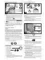
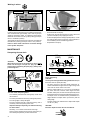
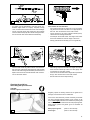
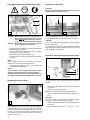
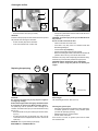
Chain Saw
Safety
Instructions
Maintenance
Information
Checking the chain lubrication
Checking the safety chain brake
6
M
N
Do not work with the saw without first checking the chain
brake!
- Start the engine as described (make sure you have a good
footing, and place the saw on the ground in such a way that
the blade is free of contact).
- Grasp the tubular handle firmly with one hand and hold the
grip with the other.
- With the engine running at moderate speed, press the hand
guard (C/1) in the direction of the arrow with the back of your
hand until the chain brake engages. The chain should stop
immediately.
- Immediately release the throttle and release the chain
brake.
IMPORTANT: If the chain does not stop immediately when
you test the chain brake, do NOT use the saw! Take the saw
to a MAKITA service center.
Never work with the chain saw withoute sufficient chain lubrication. Otherwise the service life of the chain and guide bar will be
reduced.
Before starting work check the oil level in the tank and the oil feed.
Check the oil feed rate as described below:
- Start the chain saw.
- Hold the running chain saw approx. 15 cm above a trunk or
the ground (use an appropriate base).
If the lubrication is sufficient, you will see a light oil trace because
oil will be flung off the sawing device.
3
Adjusting the carburetor
1
2
CAUTION:
Optimum perfornance can only be achieved if the carburetor is adjusted correctly. For this work, which should be
carried out by an expert, the engine must be warmed up for
a period of 3-5 min. and the air filter must be clean.
The carburetor has been adjusted by MAKITA on the basis of
atmosheric pressure conditions at sea level. Other atmospheric pressure conditions or the running-in process of a new
engine may require readjustment of the carburetor.
It is urgently recommended to use a revolution indicator (O/1)
(order number 950 233 210) in order to achieve a correct
adjustment of the carburetor. Adjust the carburetor using a 4
mm screwdriver.
O
speed
4
STOP
Basic adjustment (step 3)
- First, carefully turn the 2 adjusting screws for the main jet
(O/3) and the idle jet (O/4) to the right (clockwise) until you
feel them stop.
- Now turn both screws one turn to the left (counter-clockwise).
2
The screwdriver shown (O/2) (order number 944 340 001) has
a molded-on lug to assist in adjustment.
For adjusting the carburetor correctly the following steps
must be carried out:
1. Warm up engine
STOP
2. Switch off engine
3. Basic adjustment
4. Start engine
2
1
5. Set idle speed
6. Adjust speed
7. Check idling speed
8. Check acceleration
9. Check max. speed or output
10. Repeat adjustment procedure starting with step 5, until
idling speed, max. speed and acceleration are reached
with the adjustment made.
1
Set idle speed (step 5)
- If the chain turns when the engine is idling, unscrew the
throttle-valve stop screw (O/speed) until the chain stops. If
the engine runs unevenly, screw the screw (O/speed) back
in.
- Idling speed should be 2,600 rpm.
Adjust speed (output) (step 6)
- Adjust the speed by adjusting the main jet screw (O/3) to
11,500 rpm (DCS 340, 341), 12,000 rpm (DCS 400, 401).
Check idle speed (item 7)
- After having adjusted the max. speed ensure the idle speed
is set to 2,600 1rpm. (the chain must not turn). Use the idle
jet screw (O/4) to regulate it. Turn in the screw (O/4) to speed
up, and turn out the screw (O/4) to speed down the engine.
Check acceleration (item 8)
- Now check the acceleration, i. e. the time necessary for
speeding up from idle speed to max. speed. To do this,
press the throttle lever hard.
- If the acceleration is too low, turn out the idle jet screw
(O/4) approx. 1/8 rotation.
Do not run the engine without load a high speed, open
throttle fully only, if you are sawing!
23
Working in winter
normal operation
2
subfreezing operation
1
3
A
B
In order to prevent carburetor icing in conditions of low temperature combined with high humidity, and in order to get up to
operating temperature faster in subfreezing temperatures,
heated air can be taken from the cylinder (marking (circled) on
insert in "snowflake" position).
At temperatures above freezing the carburetor must NOT be
fed heated air (marking (circled) on insert in "sun" position).
Failure to follow these instructions can lead to damage
to the cylinder and piston!
-
Remove the filter cover (B/1).
-
Position the universal wrench (B/2) as shown above and
push the insert (B/3) out by tapping the wrench.
-
Put the insert (B/3) back in in the appropriate position, i.e. with
the marking next to the sun symbol for normal operation or
the snowflake symbol for subfreezing operation.
-
Replace filter cover (B/1).
MAINTENANCE
Sharpening the saw chain
0.65 mm
(.025")
STOP
0.65 mm
(.025")
CAUTION:
Before doing any work on the guide bar or chain, always
switch off the engine and pull the plug cap off the
spark plug (see "Replacing the spark plug"). Always wear
protective gloves!
min.
3 mm (0.11”)
✓
D
✓
Proper sharpening:
CAUTION:
Use only chains and guide bars designed for this saw (see
the Extract from the spare-parts list)!
-
All cutters must be of the same length (dimension a).
Cutters with different lengths result in rough running of the
chain and can cause cracks in the chain.
-
Minimum cutter length is 0.11" (3 mm). Do not resharpen
the chain when the minimum cutter length has been
reached; at this point, the chain must be replaced (see the
Extract from the spare-parts list and "Replacing the chain").
-
The depth of the cut is determined by the difference in
height between the depth limiter (round nose) and the
cutting edge.
-
The best results are obtained with a depth-limiter depth
of 0.65 mm (.025").
C
The chain needs sharpening when:
-
The sawdust produced when sawing damp wood looks
like wood flour.
-
The chain penetrates the wood only under great pressure.
-
The cutting edge is visibly damaged.
-
The saw is pulled to the left or right when sawing. This is
caused by uneven sharpening of the chain.
Important: Sharpen frequently, but without removing
too much metal!
Generally, 2 or 3 strokes of the file will be enough.
Have the chain resharpened at a service center when you
have already sharpened it yourself several times.
24
CAUTION:
Excessive depth increases the risk of kickback!
E
-
-
F
All cutters must be sharpened to the same angle, 30°.
Different angles result in a roughly, irregularly running
chain, increase wear and tear and cause chain breakage.
The 85° front rake of the cutter results from the cut depth
of the round file. If the proper file is used in the right manner,
the correct front rake will be obtained automatically.
Files and how to work with them
-
Use a special round file for chains (dia. 4 mm) for sharpening the chain. Normal round files are not appropriate for
this work. See "Accessories" for the order number.
-
The file should cut only when pushed forwards (arrow).
Lift the file when leading it backwards.
-
First sharpen the shortest cutter. The length of this cutter
is then the standerd for all other cutters of the chain.
-
Always guide the file horizontally (90o to the guide bar).
4/5
30°
G
-
The file holder makes file guidance easier. It is marked for
the correct 30° sharpening angle (keep the marks parallel
with the chain when filing, see illustration) and limits the cut
depth to the correct 4/5 of the file diameter. See "Accessories" for the order number.
H
I
-
After having sharpened the chain, the height of the depth
limiter must be checked by means of a chain gauge. See
"Accessories" for the order number.
-
Correct even the smallest excess height with a special flat
file (H). See "Accessories" for the order number.
-
Round off the front of the depth limiter (I).
Cleaning the guide bar,
lubricating the sprocket nose
CAUTION:
Protective gloves must be worn.
Regularly inspect the bearing surfaces of the guide bar for
damage, and clean them with a suitable tool.
If the saw is used intensively it will be necessary to lubricate
the return sprocket bearings regularly (once a week). To do
this, first thoroughly clean the 2 mm hole at the tip of the guide
bar, and then press in a small amount of multi-purpose grease.
Multi-purpose grease and grease guns are available as
accessories.
J
Multi-purpose grease
Grease gun
(order no. 944 360 000)
(order no. 944 350 000)
25
Cleaning the brake band and sprocket interior
Replacing the saw chain
CAUTION:
STOP
Use only chains and guide bars designed for this saw (see
the Extract from the spare-parts list)!
6
2
1
2
3
7
4
A
5
C
1
D
CAUTION: Before doing any work on the guide bar or
chain, always switch off the engine and pull
the plug cap off the spark plug (see "Replacing
the spark plug"). Always wear protective gloves!
Check the sprocket (C/1) before mounting a new chain.
CAUTION: Start the chain saw only after having assembled it completely and inspected!
Worn out sprockets (D) may damage the new chain and must
therefore be replaced.
-
Do not attempt to replace the sprocket yourself. Sprocket
replacement requires special training and tools and must be
done at a MAKITA service center.
-
Remove the sprocket guard (A/1) (See "PUTTING INTO
OPERATION" figs. A and B).
Turn the chain tightener screw (A/2) to the left (counterclockwise) until you feel resistance.
Remove the chain (A/3) and guide bar (A/4).
Clean the interior with a brush, in particular the brakeband
area (A/5).
The sprocket is located underneath the clutch drum (C/2).
CAUTION:
Replacing / cleaning the spark arrester screen
NOTE:
Make sure that no residue or contaminants remain in the oil
guide groove (A/6) and the chain tightener (A/7).
- For replacing the guide bar, chain, and sprocket see
"PUTTING INTO OPERATION".
2
NOTE:
The chain brake is a very important safety device and like
any other component subject to normal wear and tear.
Regular inspection and maintenance are important for your
own safety and must be done by a MAKITA service center.
Replacing the suction head
3
E
4
5
6
1
The spark arrester screen should be checked and cleaned
regularly.
-
Unscrew the muffler bolts (E/1) and remove the protective
screen (E/2).
-
Carefully remove the muffler (E/3).
NOTE: If the muffler gasket (E/4) is damaged, replace it.
-
Unscrew bolt (E/6) and remove the spark arrester screen
(E/5).
CAUTION:
1
B
The felt filter (B/1) of the suction head can become clogged. It
is recommended to replace the suction head once every three
months in order to ensure unimpeded fuel flow to the carburetor. To remove the suction head for replacement, pull it
out through the tank filler neck using a piece of wire bent at
one end to form a hook.
26
Do not use sharp or pointed objects for screen cleaning.
Damaged or misformed screen wires may result.
-
Reassemble the spark arrester screen (E/5) and tighten the
screw (E/6).
-
Tighten muffler bolts (E/1) to 5.6 +0.07 ft. lbs. (8.0 +0.1 Nm).
Cleaning the air filter
3
2
STOP
E
-
F
1
-
Remove the filter cover (E/1) (2 screws).
CAUTION:
Grasp the top and bottom sections of the air filter as shown
in figure F and pull apart.
Press the choke (E/2) up to shut the choke valve and to prevent
dirt particles from entering the carburetor.
CAUTION: To prevent injury to the eyes, do NOT blow out
dirt particles!
-
Pull the air filter (E/3) off the carburetor.
Do not use fuel to clean the air filter.
-
Cover the carburetor with a clean cloth.
-
Clean the air filter with a soft brush.
-
If the filter is very dirty, clean it in lukewarm water with
dishwashing detergent.
-
Let the air filter dry completely.
-
Put the top and bottom sections back together.
-
Before re-installing the air filter, check the choke valve for dirt
particles. If there are any, remove them with a brush.
If the filter is very dirty, clean it frequently (several times a day),
because only a clean air filter provides full engine power.
CAUTION: Replace damaged air filters immediately.
Pieces of cloth or large dirt particles can destroy the
engine!
Replacing the spark plug
STOP
1
.020" (0.5 mm).
H
G
CAUTION:
Do not touch the spark plug or plug cap if the engine is
running (high voltage).
Switch off the engine before starting any maintenance work.
A hot engine can cause burns. Wear protective gloves!
The spark plug must be replaced in case of damage to the
insulator, electrode erosion (burn) or if the electrodes are very
dirty or oily.
- Remove the filter cover (see "Cleaning the air filter" above,
Fig. E/1).
- Pull the plug cap (G/1) off the spark plug. Use only the
combination wrench supplied with the saw to remove the
spark plug.
Electrode gap
The electrode gap must be .020" (0.5 mm).
Checking the ignition spark
-
Press the loosened spark plug with the ignition cable firmly
connected against the cylinder using insulated pliers
(not near the spark plug opening).
-
ON/OFF switch in the "I" (ON) position.
-
Pull the starter cable hard.
If the function is correct, an ignition spark must be visible
near the electrodes.
CAUTION: Use only the following spark plugs:
NGK BPMR 6F or CHAMPION RDJ-7Y.
27
Instructions for daily and periodic maintenance
To ensure a long servicelife and to prevent any damage the maintenance work described in the following must be performed
regularly. The product guarantee will be automatically invalidated if this maintenance is not carried out regularly and according to
the instructions.
Perform the following servicing work daily after use. Make a habit of it, it does not require much time and your saw will always function
properly.
Possibly hidden faults can be detected in this manner before causing expensive and annoying interruptions of your work. In case
you should detect a fault in the safety equipment when performing daily servicing, the saw must not be used before elimination of
the fault. The user of the chain saw must not perform maintenance work which is not described in the instruction manual. All such
work must be carried out by a MAKITA service center.
Page
General
Chain saw
Saw chain
Chain brake
Guide bar
Before each start
Saw chain
Guide bar
Chain lubrication
Chain brake
OFF switch,
Safety locking button,
Throttle lever
Fuel/oil tank
plug
Every day
Every week
Air filter
Guide bar
Guide bar support
Idle speed
Clean exterior, check for damage. In case of damage,
have repaired by a qualified service center immediately
Sharpen regulary, replace in good time
Have inspected regularly at an authorized service center
Turn over to ensure even wear of bearing surfaces
Replace in good time
24
19
Functional check
22
23
20
Check for tightness
Clean
Check for damage, clean oil intake bore
Clean, in particular the oil guide groove
Check that a sufficient difference is existing between
idlind speed and engaging speed, to ensure that the chain
is in standstill while the engine is idling.
Clean to ensure proper air cooling
Clean (remove filter cover for access)
Clean the brake band (sawdust, oil)
Check and replace if necessary
Check tightness of mounting, clean spark arrester screen
Check
Every 3 months
Suction head
Fuel, oil tanks
Replace
Clean
Storage
Chain saw
Clean exterior, check for damage. In case of damage,
have repaired by a qualified service center immediately
Demount, clean and oil slightly
Clean the guide groove
Empty and clean
Run empty
Fuel, oil tanks
Carburetor
19
Inspect for damage and sharpness
Check chain tension
Check for damage
Functional check
Functional check
Fan housing
Carburetor interior
Chain brake
Spark plug
Muffler
Chain guide
Guide bar/chain
24-25
27
22
22, 26
23
27
26
27
26
25
26
26
Service, spare parts and guarantee
Maintenance and repair
The maintenance and repair of modern engines as well as all safety devices require qualified technical training and a special
workshop equipped with special tools and testing devices.
We therefore recommend that you consult a MAKITA service center for all work not described in this instruction manual.
The MAKITA service centers have all the necessary equipment and skilled and experienced personnel, who can work out costeffective solutions and advise you in all matters.
Please contact the general agent or importer indicated on the back cover of this Instruction Manual, who will gladly provide you with
the address of your nearest MAKITA service center.
28
Spare parts
Reliable long-term operation, as well as the safety of your chain saw, depend among other things on the quality of the spare parts
used. Use only original MAKITA parts, marked
Only original spare parts and accessories guarantee the highest quality in material, dimensions and function.
Original spare parts and accessories can be obtained from your local dealer. He will also have the spare part lists to determine the
required spare part numbers, and will be constantly informed about the latest improvements and spare part innovations.
Please bear in mind that if parts other than original MAKITA spare parts are used, this will automatically invalidate the MAKITA product
guarantee.
Guarantee
MAKITA guarantees the highest quality and will therefore reimburse all costs for repair by replacement of damaged parts resulting
from material or production faults occurring within the guarantee period after purchase. Please note that in some countries particular
guarantee conditions may exist. If you have any questions, please contact your salesman, who is responsible for the guarantee of
the product.
Please note that we cannot accept any responsibility for damage caused by:
• Disregard of the instruction manual.
• Non-performance of the required maintenance and cleaning.
• Incorrect carburetor adjustment.
• Normal wear and tear.
• Obvious overloading due to permanent exceeding of the upper performance limits.
• Use of guide bars and chains which have not been approved.
• Use of guide bar and chain lengths which have not been approved.
• Use of force, improper use, misuse or accidents.
• Damage from overheating due to dirt on the fan housing.
• Work on the chain saw by unskilled persons or inappropriate repairs.
• Use of unsuitable spare parts or parts which are not original MAKITA parts, insofar as they have caused the damage.
• Use of unsuitable or old oil.
• Damage related to conditions arising from lease or rent contracts.
Cleaning, servicing and adjustment work is not covered by the guarantee. All repairs covered by the guarantee must be performed
by a MAKITA service center.
Troubleshootig
Malfunction
System
Observation
Cause
Chain does not run
Chain brake
Engine runs
Chain brake actuated.
Engine does not start or
only with difficulty
Ignition system
Ignition spark
Malfunction in fuel supply system, compression system, mechanical malfunction.
Switch on STOP, fault or short-circuit in the
wiring, plug cap or spark plug defective.
Choke in wrong position, carburetor defective,
suction head dirty, fuel line bent or interrupted.
Cylinder base packing ring defective, radial
shaft packings defective, cylinder or piston rings
defective
Spark plug does not seal.
Spring in starter broken, broken parts
inside the engine.
No ignition spark
Fuel supply
Fuel tank is filled
Compression
system
Inside
Mechanical
malfunction
Outside
Starter does not engage
Warm start difficulties
Carburetor
Fuel tank is filled
Ignition spark
Wrong carburetor adjustment.
Engine starts, but
dies immediately
Fuel supply
Fuel tank is filled
Wrong idling adjustment, suction head or
carburetor dirty. Tank venting defective, fuel line
interrupted, cable defective, STOP switch
defective. Starting valve dirty (DCS 341/401).
Insufficient power
Several systems
may be involved
simultaneously
Engine is idling
Air filter dirty, wrong carburetor adjustment,
muffler clogged,exhaust channel in cylinder
clogged.
No chain lubrication
Oil tank/pump
No oil on the chain
Oil tank empty.
Oil guide groove dirty.
Oil-pump adjusting screw incorrectly adjusted.
29
Extract from the spare parts list
DCS 340 / DCS 341
DCS 400 / DCS 401
Use only original MAKITA parts. For repairs and replacement of other parts, see
your MAKITA service center.
Pos. MAKITA-No.
1
442 030 661
442 035 661
442 040 661
522 092 646
522 092 652
522 092 656
952 100 633
028 213 670
923 208 004
941 716 131
010 114 010
965 603 018
028 173 141
010 114 050
963 224 035
965 450 040
963 100 041
965 524 062
928 405 000
908 205 605
021 174 111
915 135 100
021 174 340
021 174 320
3
2
3
4
5
6
7
8
9
10
11
12
13
14
15
16
17
18
19
20
2
1
Qty.
1
1
1
1
1
1
1
1
1
1
1
1
1
1
1
1
1
1
2
2
1
1
1
1
Denomination
Sprocket nose bar 30 cm (12")
Sprocket nose bar 35 cm (14")
Sprocket nose bar 40 cm (16")
Saw chain 3/8" for 30 cm
Saw chain 3/8" for 35 cm
Saw chain 3/8" for 40 cm
Chain protection for 30-40 cm
Sprocket guard, cpl.
Hexagonal nut M8
Universal wrench SW 13/16
Suction head
Spark plug NGK BPMR 6F
Air filter
Fuel tank plug, cpl.
O-Ring 24 x 3.5
Oil tank plug, cpl.
Gasket
Gasket
Spring washer
Fillister screw
Protective screen
Screw 3.5 x 9.5
Spark arrester screen
Muffler
20
9
8
19
18
16(2)
10
17 15(2)
11
12
13
14
7
5
4
23
27
24
6
25
Accessories (not delivered with the chain saw)
22
21
26
30
21
22
23
24
25
953 100 090
953 004 010
953 003 090
953 003 060
953 030 010
1
1
1
1
1
26
27
-
944 340 001
950 233 210
949 000 031
1
1
1
Chain gauge
File handle
Round file, dia. 4 mm
Flat file
File holder
(with 4 mm dia. round file)
Carburetor screwdriver
Tachometer
Combined can
(for 5l fuel, 2.5l oil)